-
Contents
-
Table of Contents
-
Bookmarks
Quick Links
User’s
Manual
Model
GX10/GX20/GP10/GP20/GM10
Communication Command
User’s Manual
IM 04L51B01-17EN
9th Edition
Related Manuals for YOKOGAWA GX10
Summary of Contents for YOKOGAWA GX10
-
Page 1
User’s Manual Model GX10/GX20/GP10/GP20/GM10 Communication Command User’s Manual IM 04L51B01-17EN 9th Edition… -
Page 3: Introduction
YOKOGAWA is strictly prohibited. • The TCP/IP software of this product and the documents concerning it have been developed/created by YOKOGAWA based on the BSD Networking Software, Release 1 that has been licensed from the Regents of the University of California.
-
Page 4: Recorder Version And Functions Described In This Manual
Recorder Version and Functions Described in This Manual Edition Product Explanation GX/GP: Version 1.01 and later — GX/GP: Version 1.02 and later Feature additions. GX/GP: Version 1.03 and later Electromagnetic relay type analog input modules have been added. Feature additions. GX/GP: Version 2.01 and later Support for GX20/GP20 large memory type and expandable I/O has been added.
-
Page 5: How To Use This Manual
For details on the features of the recorder and how to use it, see the following manuals. • Model GX10/GX20/GP10/GP20 Paperless Recorder First Step Guide (IM 04L51B01- 02EN) • Model GX10/GX20/GP10/GP20 Paperless Recorder User’s Manual (IM 04L51B01-01EN) •…
-
Page 6
Blank… -
Page 7: Table Of Contents
Contents Introduction …………………………i Recorder Version and Functions Described in This Manual …………..ii How to Use This Manual ……………………..iii Conventions Used in This Manual ………………….iii Chapter 1 Using Dedicated Commands (General) Operations over an Ethernet Network ……………..1-1 1.1.1 Preparing the Instrument ………………….1-1 1.1.2 Sending Commands and Receiving Responses …………..1-1 Operations over the Serial Interface (RS-232, RS-422/485, USB, Bluetooth) ….
-
Page 8
Contents 2.10.15 Modbus Communication Log (FLog) ………………2-139 2.10.16 FTP Client Log (FLog) ………………….2-140 2.10.17 SNTP (Time Adjustment) Client Log (FLog) ……………2-141 2.10.18 E-Mail Client Log (FLog) ………………..2-142 2.10.19 Web Log (FLog) …………………….2-143 2.10.20 SLMP Log (FLog) …………………..2-144 2.10.21 Control Alarm Summary (FLog) ………………2-145 2.10.22 Control Summary (FLog) ………………..2-146 2.10.23 Detail Event Log Output (FEventLog) (/AS) ……………2-148 2.10.24 External Storage Medium and Internal Memory File List (FMedia) ……..2-157… -
Page 9: Chapter 1 Using Dedicated Commands (General)
Configure the recorder to connect to the Ethernet network that you want to use. For instructions on how to configure the recorder, see section 1.17, “Configuring the Ethernet Communication Function“ in the Model GX10/GX20/GP10/GP20 Paperless Recorder User’s Manual (IM 04L51B01-01EN) or section 2.18, “Configuring the Ethernet Communication Function,”…
-
Page 10: Preparing The Instrument
Configure the recorder to use serial communication. For instructions on how to configure the recorder, see section 1.18, “Configuring the Serial Communication Function (/C2 and / C3 options)“ in the Model GX10/GX20/GP10/GP20 Paperless Recorder User’s Manual (IM 04L51B01-01EN) or section 2.19, “Configuring the Serial Communication Function (/ C3 option),”…
-
Page 11: Connection Procedure (Gx/Gp)
1.2 Operations over the Serial Interface (RS-232, RS-422/485, USB, Bluetooth) 1.2.3 RS-232 Connection Procedure (GX/GP) Connect a cable to the 9-pin D-sub RS-232 connector. Connection • Connector pin arrangement and signal names Each pin corresponds to the signal indicated below. The following table shows the signal name, RS-232 standard, JIS, and ITU-T standard signals.
-
Page 12
1.2 Operations over the Serial Interface (RS-232, RS-422/485, USB, Bluetooth) Handshaking When using the RS-232 interface for transferring data, it is necessary for equipment on both sides to agree on a set of rules to ensure the proper transfer of data. The set of rules is called handshaking. -
Page 13
1.2 Operations over the Serial Interface (RS-232, RS-422/485, USB, Bluetooth) • CS-RS Data transmission control Hardware handshaking is performed between the GX/GP and the PC. When the CS signal becomes False while sending data to the PC, the GX/GP stops the data transmission. -
Page 14: Rs-422/485 Connection Procedure
RS-422/485 Port Converter SDA(–) TD(–) SDB(+) TD(+) RDA(–) RD(–) RDB(+) RD(+) SHIELD EARTH There is no problem of connecting a 220-Ω terminator at either end if YOKOGAWA’s PLCs or temperature controllers are also connected to the communication line. IM 04L51B01-17EN…
-
Page 15
1.2 Operations over the Serial Interface (RS-232, RS-422/485, USB, Bluetooth) • Four-wire system Generally, a four-wire system is used to connect to a host device. In the case of a four- wire system, the transmission and reception lines need to be crossed over. Terminator (external) 120 Ω… -
Page 16
The recommended converter is given below. SYSMEX RA CO.,LTD./MODEL RC-770X, LINE EYE/SI-30FA, YOKOGAWA/ML2 Some converters not recommended by Yokogawa have FG and SG pins that are not isolated. In this case, do not follow the diagram on the previous page (do not connect anything to the FG and SG pins). -
Page 17: Usb Connection Procedure (Gm)
1.2 Operations over the Serial Interface (RS-232, RS-422/485, USB, Bluetooth) 1.2.5 USB Connection Procedure (GM) The procedure to connect a GM to the PC via USB is shown below. For instructions on how to use the PC, see the user’s manual for your PC. Configuring the GM Turn the USB communication function on (default value is on).
-
Page 18: Bluetooth Connection Procedure (Gm, /C8 Option)
1.2 Operations over the Serial Interface (RS-232, RS-422/485, USB, Bluetooth) 1.2.6 Bluetooth Connection Procedure (GM, /C8 option) The procedure to connect a GM to the PC via Bluetooth is shown below. For instructions on how to use the PC, see the user’s manual for your PC. Configuring the GM Turn the Bluetooth function on (default value is on).
-
Page 19: Chapter 2 Commands And Responses
Chapter 2 Commands and Responses Command Transmission and Recorder Responses 2.1.1 General Communication The recorder can work with various applications through the use of commands. The communication that is achieved through commands is referred to as “general communication.” 2.1.2 Command Types and Functions The following types of commands are available.
-
Page 20
2.1 Command Transmission and Recorder Responses Notes on Writing Commands in a Series • Only setting commands can be written in a series. • Queries (see the next section) cannot be written in a series. • If there is an error in one of the commands in a series, the commands before it are canceled, and those after it are not executed. -
Page 21
2.1 Command Transmission and Recorder Responses Parameters Parameters are characteristic values that are attached to commands. Notes on Writing Parameters • Write parameters in their appropriate order. • Spaces around and in the middle of parameters are ignored. Exception is the character strings that users specify. -
Page 22: Recorder Responses
2.1 Command Transmission and Recorder Responses 2.1.4 Recorder Responses The recorder returns the following responses to commands. • If the recorder successfully completes the processing of a received output request command, it outputs the requested data. • If the recorder successfully completes the processing of a received command that is not an output request command, it outputs an affirmative response.
-
Page 23: List Of Commands
2-23 SRangeAICurrent Measurement range of current List of Commands input type AI channel 2-24 SRangePulse Measurement range of pulse input channel 2-25 SRangeDI Measurement range of DI Unless specified otherwise, AI, AO, DI, DO, PI, and PID channel represent I/O channel types. 2-25 SRangeDO DO channel operation…
-
Page 24
2.2 List of Commands 2-39 2-49 Waveform display zone (/MC) Date format SZoneCom SDateFormat 2-39 2-49 SScaleCom Scale display (/MC) [GX/GP] SDst Daylight saving time 2-40 2-49 SBarCom Bar graph display (/MC) SLang Language 2-40 2-50 SPartialCom Partial expanded display (/ STemp Temperature unit MC)[GX/GP]… -
Page 25
2.2 List of Commands 2-57 2-69 SModCCmd Modbus client transmission SFavoriteKind Favorite screen [GX/GP] command (/MC) Multi Batch Setting Commands (/BT) Page 2-58 2-69 SServer Server function Batch text SMltTextField 2-58 2-69 SServerEncrypt Server communication SMltFileHead File header encryption 2-69 SMltFileName File naming rule 2-58… -
Page 26: Output Commands
2.2 List of Commands 2-83 2-30 Reference source of EXPV PID control module channel SCtrlCalc SZoneIO and RSP display (zone high limit, zone 2-83 SCtrlFilterSP Remote SP filter low limit) 2-30 2-83 SScaleIO PID control module channel SCtrlRatioSP Remote SP ratio 2-83 display (scale display position, SCtrlBiasSP…
-
Page 27: Operation Commands
2.2 List of Commands 2-99 2-108 FPrgEvent PV event and time event OSLMPRestore Manually restores SLMP (/E4) 2-108 information output (/PG) Individual re-transmission output OtransChAO 2-99 FPrgEnd Program control end signal status (AO channel) control 2-108 OtransAllAO Collective re-transmission output output (/PG) 2-100 (AO channel) control…
-
Page 28: Instrument Information Commands
• User restriction is placed on the operation. Command Applicable Models The following table lists the commands that are invalid SViewAngle GX10, GP10 according to the limitation types (p1 of the SOpeLimit SMultiPattern GX20, GP20 command or p2 of the SUserLimit command). SMultiKind…
-
Page 29: How To Use Commands
2.2 List of Commands 2.2.7 How to Use Commands 2.2.8 Device Nomenclature in Command Descriptions When Using Ethernet • When not using the login function The following nomenclature is used in the command When you connect a PC to the recorder, the recorder descriptions in section 2.4 to distinguish the devices.
-
Page 30: Parameters
Expandable I/O installed 0 to 6 recording GX20-2/GP20-2: 001 to 1000 [GX/GP] When the unit is GX10/GP10 0 to 2 GM10-1: 1 to 500 display data When the unit is GX20/GP20 0 to 9 Module number GM10-2: 1 to 1000…
-
Page 31: Specifying A Range
AI: 1 or 2, AO: 1 or 2, DI: 1 to 8, DO: 1 registered to to 8 GM10: 20 display groups Logic math GX10: 1 to 20 number GX20-1/GX20-2, GM10-1/GM10-2: 1 Modbus server GX10/GP10/GX20-1/GP20-1: 1 to 16 to 50…
-
Page 32: Setting Commands
When specifying a scan interval of 50 ms or Setting Commands less, the number of channels must be within the limits. (For the limits to the number of channels for each scan interval, see the main unit’s User’s Manual (IM 04L51B01-01EN, or IM 04L55B01-01EN).) SScan The shortest scan interval of the modules…
-
Page 33
2.4 Setting Commands 4-wire RTD type 2 If the scan interval is 50 ms or less, the number of installed modules and the number of channels must Scan Mode Integration time (p4) be within their limits. interval (p3) Auto 50Hz 60Hz Common 3 The shortest scan interval of the module must be… -
Page 34
2.4 Setting Commands SBOLmtAI SModeDI Upper and Lower Burnout Limits of AI DI Module Module Sets the mode of a DI module. Syntax Sets the burnout limits for the general signal range of an SModeDI,p1,p2,p3 AI module (excluding current input type AI modules). No /MT SModeDI,p1,p2,p3,p4 Syntax… -
Page 35: Recording Mode
2.4 Setting Commands SScaleOver SMemKeyConfirm Detection of Values That Exceed the Record Confirmation Action [GX/GP] Scale Sets the record confirmation action. Syntax SMemKeyConfirm,p1 Sets how to detect measurement over-range. Syntax p1 Enable or disable confirmation screen SSclOver,p1 (Off, On) /P1 How to detect values that exceed the Query SMemKeyConfirm? scale…
-
Page 36
2.4 Setting Commands Scan interval Recording intervals less than or SEventData equal to 50 ms 1ms, 2ms, 5ms, 10ms, 20ms, Event Data Recording 50ms Sets the event data recording mode. 2ms, 10ms, 20ms, 50ms Syntax 5ms, 10ms, 20ms, 50ms SEventData,p1,p2,p3,p4,p5,p6 10ms 10ms, 20ms, 50ms p1 Scan group (1 or 2) -
Page 37
2.4 Setting Commands Description SRecDisp • You cannot use this command to configure settings while recording is in progress. Channel for Recording Display Data • You cannot use this command to configure settings Sets the channel for recording display data. while computation is in progress. -
Page 38
2.4 Setting Commands SRecManual STextField Channel for Recording Manual Sampled Batch Text Data Sets a batch text. Syntax STextField,p1,p2,p3 Sets the channel for recording manual sampled data. Syntax p1 Field number (1 to 24) SRecManual,p1,p2,p3 p2 Title (up to 20 characters, UTF-8) p1 Number (1 to 50) p3 Character string (up to 30 characters, p2 Channel type… -
Page 39
2.4 Setting Commands SFileName SFileFormat File Naming Rule Display/Event Data File Format Sets the file naming rule for data files. Sets the file format of display data files and event data Syntax files. SFileName,p1,p2 Syntax p1 File naming rule SFileFormat,p1 p1 File format (Binary, Text) Date Date… -
Page 40
2.4 Setting Commands p2 Input type (GS) SRangeAI p3 Range (see “Description.”) Measurement Range of AI Channel P4 Calculation type (Scale) p5 Span lower limit Sets the measurement range of an AI channel. Unused Channels p6 Span upper limit Syntax SRangeAI,p1,p2 p7 Bias (–999999 to 999999) p1 Channel number… -
Page 41
2.4 Setting Commands • You cannot use this command to configure settings SRangeAICurrent while computation is in progress. • If p2=TC/RTD/DI/OHM, you cannot specify p4=Sqrt. Measurement Range of Current Input • If p2=GS, you cannot specify p4=Off/Delta. Type AI Channel •… -
Page 42
2.4 Setting Commands p5 Span lower limit p1 Channel number p6 Span upper limit p2 Input type (PulseInput) p7 Bias (–999999 to 999999) p3 Range (LevelRange, ContactRange) p8 Decimal place (0 to 5) LevelRange Level p9 Scaling lower limit ContactRange Contact p10 Scaling upper limit p4 Chattering filter (On, Off) p11 Unit (up to 6 characters, UTF-8) -
Page 43
2.4 Setting Commands • p2=Pulse can be specified when the math function (/ SRangeDI MT) is installed. Measurement Range of DI Channel • If p2=Pulse, p4=Delta or Scale cannot be specified. Sets the measurement range of a DI channel. • p2=Pulse cannot be specified when the operation Unused Channels mode of the DI module is set to Remote. -
Page 44
2.4 Setting Commands Syntax SRangeDO,p1,p2,p3,p4,p5,p6 p5 Span high limit p3= AO_0-20mA 0 to 20000 p1 Channel number p3= AO_4-20mA 4000 to 20000 p2 Output type (Manual) p6 Preset value (0 to 22000) p3 Span lower limit (0 to 1) p7 Reference channel type (Input, Math, P4 Span upper limit (0 to 1) Com) p5 Unit (up to 6 characters, UTF-8) -
Page 45
2.4 Setting Commands SFilter SRjc Sets the First-Order Lag Filter Reference Junction Compensation Method Sets the first-order lag filter of a high-speed AI channel when a high-speed AI module is installed. Sets the reference junction compensation method of an AI Syntax SFilter,p1,p2,p3 channel. -
Page 46
2.4 Setting Commands SAlarmIO,0001,2,On,H,18000,On,DO, SAlarmIO 0205 Description Alarm • You cannot set this on a “Skip” channel. Sets the alarm for an AI, DI, or PI channel. • If p3=Off, you cannot set p4 or subsequent Do Not Set Alarms parameters. -
Page 47
Note SAlmDlyIO,p1,p2,p3,p4 p1 Channel number Green p2 Hour (0 to 24) Blue p3 Minute (0 to 59) Blue violet GX10/GP10 P4 Second (0 to 59) Query GX20/GP20 SAlmDlyIO[,p1]? GM10 Example Set the channel 0001 alarm delay time to 2 Brown minutes 30 seconds. -
Page 48
2.4 Setting Commands SZoneIO SPartialIO Waveform Display Zone Partial Expanded Display [GX/GP] Sets the waveform display zone of an AI, DI, PI, AO, DO, Sets the partial-expansion display of an AI, PI, or PID or PID channel. channel waveform. Syntax Syntax SZoneIO,p1,p2,p3 SPartialIO,p1,p2,p3,p4… -
Page 49
2.4 Setting Commands Query SBandIO[,p1]? SValueIO Example For channel 0001, set a blue band in the range of -0.5000 to 1.0000. Upper/Lower Limit Display Characters SBandIO,0001,In,0,0,255,5000,10000 Sets the upper/lower limit display characters of AI, DI, DO, Description or PID channel. •… -
Page 50
2.4 Setting Commands p16 Input value of uncorrected value 5 SCalibIO p17 Instrument correction coefficient 5 p18 Sensor correction coefficient 5 Calibration Correction p19 Input value of uncorrected value 6 Sets the calibration correction for AI channels. p20 Instrument correction coefficient 6 Disable Calibration Correction p21 Sensor correction coefficient 6 Syntax… -
Page 51
2.4 Setting Commands • For math channels, SPresetAO the specified span Sets the Preset Action upper or lower limit. p3 MAX, MIN, and P-P computation when Sets the preset action of an AO channel. overflow data is detected Syntax SPresetAO,p1,p2,p3,p4 Over Computes using data that p1 Channel number… -
Page 52
2.4 Setting Commands SKConst STlogMath Constant (/MT) TLOG (/MT) Sets a constant for use in computations. Sets the TLOG of a math channel. Syntax Syntax SKConst,p1,p2 STlogMath,p1,p2,p3,p4,p5 p1 Constant number (1 to 100) p1 Channel number p2 Value (–9.9999999E+29 to –1E–30, p2 Timer Type Timer 0, 1E–30 to 9.9999999E+29, eight… -
Page 53
2.4 Setting Commands Query SAlarmMath[,p1[,p2]]? SAlarmMath Example Set a high limit alarm (H) on alarm number 2 of math channel 015. Set the alarm value to 85.0. Alarm (/MT) When an alarm occurs, output to the relay (DO Sets the alarm of a math channel. channel) at number 0105. -
Page 54
2.4 Setting Commands STagMath SBarMath Tag (/MT) Bar Graph Display (/MT) Sets the bar graph display of a math channel. Sets the tag of a math channel. Syntax Syntax STagMath,p1,p2,p3 SBarMath,p1,p2,p3 p1 Channel number p1 Channel number p2 Bar display base position p2 Tag (up to 32 characters, UTF-8) Lower p3 Tag number (up to 16 characters, UTF-8) -
Page 55
2.4 Setting Commands SBandMath SAlmMarkMath Color Scale Band (/MT) Alarm Mark (/MT) Sets the color scale band of a math channel. Sets the display of the marker that indicates the specified Syntax alarm position of a math channel. SBandMath,p1,p2,p3,p4,p5,p6,p7 Syntax p1 Channel number SAlmMarkMath,p1,p2,p3,p4,p5,p6,p7, p8,p9,p10,p11,p12,p13,p14,p15… -
Page 56
2.4 Setting Commands SRangeCom SWDCom Measurement Range (/MC) Watchdog Timer (/MC) Sets the measurement range of a communication Sets the watchdog timer of a communication channel. Channels That Do Not Use Watchdog Timers channel. Syntax Unused Channels SWDCom,p1,p2 Syntax p1 Channel number SRangeCom,p1,p2 p1 Channel number p2 Watchdog timer usage (Off) -
Page 57
2.4 Setting Commands If p7=DO Relay (DO channel) STagCom number If p7=SW Internal switch number Tag (/MC) (001 to 100) Sets the tag of a communication channel. Query SAlarmCom[,p1[,p2]]? Syntax Example Set a high limit alarm (H) on alarm number 2 STagCom,p1,p2,p3 p1 Channel number of communication channel 025. -
Page 58
2.4 Setting Commands Query SBandCom[,p1]? SBarCom Example For communication channel 025, set a blue band in the range of -0.5000 to 1.0000. Bar Graph Display (/MC) SBandCom,025,In,0,0,255,5000,10000 Sets the bar graph display of a communication channel. Description Syntax SBarCom,p1,p2,p3 • You cannot set this on a “Off”… -
Page 59
2.4 Setting Commands SAlmLimit STimer Rate-of-Change Alarm Interval Timer Sets the rate-of-change interval of the rate-of-change Sets a timer. Do Not Use Timers alarm. Syntax Syntax SAlmLimit,p1,p2 STimer,p1,p2 p1 Timer number (1 to 12) p1 Interval for the low limit on rate-of-change alarm p2 Timer type (Off) 1 to 32… -
Page 60
2.4 Setting Commands p6 Interval: Minutes (MM) (00 to 59) SEventAct p7 Timer action Event Action Single Single shot Repeat Repeat Sets an event action. Match Time Timer That Synchronizes Once a Month Syntax SEventAct,p1,p2,p3,p4,p5,p6,p7 Syntax SEventAct,p1,p2,p3,p4,p5,p6,p7,p8 SMatchTimer,p1,p2,p3,p4,p5,p6 SEventAct,p1,p2,p3,p4,p5,p6,p7,p8 p1 Match time timer number (1 to 12) p2 Type (Month) SEventAct,p1,p2,p3,p4,p5,p6,p7,p8, p3 Start time: Day (1 to 28) -
Page 61
Source Action Action Action combinations. For details, see section 1.14 in the Type Element Detail Detail 2 Detail 3 Model GX10/GX20/GP10/GP20 Paperless Recorder Number Rising, Recording Memory Start, ALL, batch User’s Manual (IM 04L51B01-01EN) or section 2.15, Falling, Stop group “Configuring the Event Action Function,”… -
Page 62
2.4 Setting Commands SReport SRepData Report Type (/MT) Report Data (/MT) Sets the type of report to create. Sets the data type and file type of reports. No Reports Syntax SRepData,p1,p2,p3,p4,p5,p6 Syntax p1 Data type 1 (Max, Min, Ave, Sum, Inst) SReport,p1 p1 Type (Off) p2 Data type 2 (Off, Max, Min, Ave, Sum,… -
Page 63
Easy to view from above Lower Easy to view from below Query SViewAngle? Example Set the view angle so that it is easy to view from above. SViewAngle,Upper Description • This command is valid for the GX10/GP10. 2-45 IM 04L51B01-17EN… -
Page 64
2.4 Setting Commands SBackColor SBarDirect Screen Background Color [GX/GP] Bar Graph Display Direction [GX/GP] Sets the screen background color. Sets the bar graph display direction. Syntax Syntax SBackColor,p1,p2,p3 SBarDirect,p1 p1 R value of RGB background colors (0 to p1 Direction 255) Horizontal Horizontal p2 G value of RGB background colors (0 to… -
Page 65
2.4 Setting Commands STrdScale STrdRate Scale [GX/GP] Trend Interval Switching [GX/GP] Set the scale. Sets the trend interval switching. Syntax Syntax STrdScale,p1,p2,p3 STrdRate,p1,p2 p1 Number of digits to display for scale p1 Trend interval switching values. Not switch Normal Normal Switch Fine Fine… -
Page 66
2.4 Setting Commands SMsgBasic STripLine Display Group Trip Line Message Writing Sets the message writing operation. Sets a trip line for a display group. Syntax Syntax STripLine,p1,p2,p3,p4,p5,p6,p7,p8 SMsgBasic,p1,p2,p3 p1 Message writing method p1 Group number (GX/GP: Common, Separate) p2 Trip line number (1 to 4) (GM: Common) p3 Enable or disable (Off, On) Write messages to all display… -
Page 67: Date Format
2.4 Setting Commands Display the month using Letter STimeZone characters (Jan, Feb, Mar, Apr, May, Jun, Jul, Aug, Sep, Time Zone Oct, Nov, Dec) Sets the time zone. Syntax Query STimeZone,p1,p2 SDateFormat? Example Set the date format to “year, month, day,” and p1 Time zone: Hour (-13 to 13) p2 Time zone: Minute (0 to 59) display the month using numerals.
-
Page 68
2.4 Setting Commands STemp SFailSts Temperature Unit Instrument Status to Output (/FL) [GX/ Sets the temperature unit. Syntax STemp,p1 Sets the instrument status to output from the fail relay (DO p1 Temperature unit channel). Syntax Celsius SFailSts,p1,p2,p3,p4,p5 p1 Memory/media status (Off, On) Fahrenheit Query p2 Measurement error (Off, On) -
Page 69
Sets touch and warning sounds. 1.18.11, “Setting USB Input Devices (/UH option)” Syntax SSound,p1,p2 in the Model GX10/GX20/GP10/GP20 Paperless p1 Touch sound (Off, On) Recorder User’s Manual (IM 04L51B01-01EN). p2 Warning sound (Off, On) Query… -
Page 70
1.18.11, alarms are in the alarm state. p4 Power supply “Setting USB Input Devices (/UH option)” in the Model GX10/GX20/GP10/GP20 Paperless Recorder User’s Last Output the previous value Manual (IM 04L51B01-01EN). Output 1… -
Page 71
For details on data types, registers, and channel SClient,FTP,On types, see section 4.5.1, “Modbus Client and Master Description Function” in the Model GX10/GX20/GP10/GP20 • Modbus client is valid on models with the /MC Paperless Recorder User’s Manual (IM 04L51B01- communication channel option. -
Page 72
2.4 Setting Commands p1 Automatic IP address acquisition (On) SClientEncrypt p2 DNS information acquisition (Off, On) p3 Automatic host name registration (Off, On) Client Communication Encryption Query SDhcp? Example Automatically obtain the IP address and DNS Sets whether to encrypt FTP client communication and SMTP client communication. -
Page 73
2.4 Setting Commands SSmtpCnct SFtpTime SMTP Client Connection Destination FTP Transfer Time Shift Server Sets the amount of time to shift file transfers that are carried out by the FTP client function. Sets the SMTP client connection destination server Syntax Syntax SFtpTime,p1,p2 SSmtpCnct,p1,p2,p3,p4,p5… -
Page 74
2.4 Setting Commands SMail SMailAlarm Destination and Behavior for Each Mail Alarm Notification Mail Target Channels Type Detects the alarm status of the specified channels and sends alarm notifications. Sets the destination and behavior for each mail type. Syntax Alarm Notification SMailAlarm,p1 Syntax p1 Channel string (up to 249 characters, up… -
Page 75
2.4 Setting Commands SMailTime SModCList Scheduled Transmission Times Modbus Client Connection Destination Server (/MC) Sets the scheduled transmission times. Syntax SMailTime,p1,p2,p3,p4 Sets the Modbus client connection destination server. p1 Recipient (1 or 2) Syntax SModCList,p1,p2,p3 p2 Reference time: Hours (HH) (00 to 23) p1 Registration number p3 Reference time: Minutes (MM) (00 to 59) p2 Server name (up to 64 characters, ASCII) -
Page 76
Query SServerEncrypt[p1]? types, see section 4.5.1, “Modbus Client and Master Example Encrypt FTP server communication. Function” in the Model GX10/GX20/GP10/GP20 SServerEncrypt,FTP,On Paperless Recorder User’s Manual (IM 04L51B01- 01EN) or section 4.5.1, “Modbus Client/Master Function,” in the Data Acquisition System GM User’s SKeepAlive Manual (IM 04L55B01-01EN). -
Page 77
2.4 Setting Commands SModLimit SWattData Modbus Server Connection Limit WT Data Allocation to Communication Channel (/E2) Enables or disables the Modbus server connection limit function. Allocates WT data to a communication channel. Syntax SModLimit,p1 Syntax SWattData,p1,p2,p3,p4,p5,p6,p7 p1 Connection limit (Off, On) p1 Allocation No Query SModLimit? -
Page 78
2.4 Setting Commands SKdcCnct SDarwinPortLimit KDC Connection Destination (/AS) Port limitation of DARWIN compatible communication Sets the KDC server for the password management. Syntax SKdcCnct,p1,p2,p3 If port limitation is on, port number 34151 only allows p1 Connection destination (Primary, reading of instantaneous data. Secondary) Syntax SDarwinPortLimit,p1… -
Page 79
Edge relay Hexadecimal BIT Syntax SSLMPCCmd,p1,p2,p3,p4,p5,p6,p7,p8, Link relay Hexadecimal BIT p9,p10,p11,p12,p13 Data register Hexadecimal INT16/UINT16/ p1 Command number (GX10/GP10: 1 to 50, INT32/UINT32/ GX20-1/GP20-1: 1 to 100, GX20-2/GP20- FLOAT Link register Hexadecimal INT16/UINT16/ 2/GM10-2: 1 to 200) INT32/UINT32/ p2 Type… -
Page 80
2.4 Setting Commands P6 Enable or disable user ID (On, Off) SOpeLimit Query SSecurity? Example Use the login function when operating the Operation Lock Details [GX/GP] recorder directly or via communication. When Sets which operations to lock. logged in, automatically log out if there is no Syntax SOpeLimit,p1,p2 user activity for 5 minutes. -
Page 81
2.3.1, “Logging In“ in the Model • You cannot enter NULL or spaces in p4 or p5. GX10/GX20/GP10/GP20 Advanced Security Function • For the characters that you can use in the specified (/AS) User’s Manual (IM 04L51B01-05EN) or section… -
Page 82
2.4 Setting Commands SUserLimit SSignIn Authority of User Sign In (/AS) Sets user operation limitations. Sets the sign in record for the measured data file. Syntax Syntax SUserLimit,p1,p2,p3 SSignIn,p1,p2,p3 p1 User limitation number (1 to 10) p1 Sign in type (Batch, File) p2 Authority of user p2 Sign in at record stop Memory… -
Page 83
2.4 Setting Commands SBTPassword SWebTimeOut Bluetooth Password (/C8) [GM] Web Auto Logout (/AS) [GM] Sets the Bluetooth password. Sets the auto logout time for web screen. Syntax Syntax SBTPassword,p1,p2 SWebTimeOut,p1 p1 Password usage (On, Off) p1 Auto logout time (Off, 10 min, 20 min, 30 min) p2 Password (up to 20 characters, ASCII) Query… -
Page 84
Watt is an option (/E2). SMonitor,p1,p2 p1 Information type (see the table below) • When p1 = Switch, p2 = 3 or 4 is valid only for the GX10/GP10. p2 Status (see the table below) Information Type Status Description SMultiPattern… -
Page 85
2.4 Setting Commands • Custom display screen (/CG) cannot be shown in a SMultiKind multi panel. Multi Panel [GX/GP] • This command can be used only when the multi batch function (/BT) is disabled. Set the screens to display on the multi panel. •… -
Page 86
2.4 Setting Commands ProgramSelect Program selection (/PG) SHomeKind ProgramRun Program operation (/ Standard Screen [GX/GP] p2 Display group number Set the standard screen. (when p1 is not CustomDisplay) For Multi Panel Customized display screen number (1 to Syntax SHomeKind,p1,p2,p3 p1 Screen type (Multi) (when p1 is CustomDisplay) p2 Multi panel number (1 to 20) Control group number (1 to 10) -
Page 87
2.4 Setting Commands p1 Batch group number (1 to the number SFavoriteKind used) p2 Field number (1 to 24) Favorite Screen [GX/GP] p3 Title (up to 20 characters, UTF-8) Set the favorite screen. p4 Character string (up to 30 characters, For Multi Panel UTF-8) Syntax… -
Page 88
2.4 Setting Commands SMltSclBmp [GX/GP] SMltGroup Scale Bitmap Display Group Sets the display group’s scale bitmap file for multi batch. Sets the display group for multi batch. Syntax Syntax SMltSclBmp,p1,p2,p3 SMltGroup,p1,p2,p3,p4,p5 p1 Batch group number (1 to the number p1 Batch group number (1 to the number used) used) p2 Display group number… -
Page 89
2.4 Setting Commands SMltMultiKind SBTTimeOut Multi Panel Type Bluetooth Communication Timeout (/C8) [GM] Sets the multi panel pattern for multi batch. Syntax SMltMultiKind,p1,p2,p3,p4,p5 Sets the Bluetooth communication timeout. p1 Batch group number (1 to the number Syntax SBTTimeOut,p1 used) p1 Timeout function (Off, 1min, 2min, 5min, p2 Registration number (1 to 20) 10min) Query… -
Page 90
2.4 Setting Commands Query SSchedule[,p1]? SWebCustomMenu Example Set schedule number 1 with the date set to December 24, 2015, the notification set to 5 Web Monitor Screen days before, and the renotification interval to Sets the contents displayed on the monitor screens. 1 hour. -
Page 91
2.4 Setting Commands SMasterScanGrp SCtrlScan Master Scan Interval Control Period Sets the master scan interval when the measurement Sets the control period. Syntax mode is set to dual interval. SCtrlScan,p1,p2,p3 Syntax p1 Unit number SMasterScanGrp,p1 p1 Scan group number (1 or 2) Fixed to “–”. -
Page 92
2.4 Setting Commands SCtrlLoopAction SCtrlSPPID Loop Control Number of SP Groups, Number of PID Groups Sets the loop control. Syntax SCtrlLoopAction,p1,p2,p3,p4,p5,p6 Sets the number of SP groups, number of PID groups p1 Loop number Syntax SCtrlSPPID,p1,p2,p3 p2 PID initial value p1 Loop number Temperature PIDDef_TEMP… -
Page 93
2.4 Setting Commands SCtrlDIRegist,0,2,A-M_LP1,DI1 SCtrlDIRegist Description Contact Registration • This command is valid when a PID Control Module is installed. Registers a contact Syntax • SCtrlDIRegist,p1,p2,p3,p4 ALM*_Lx(*=1 to 4, x=1 or 2) indicates the alarm p1 Unit number status. ALM*_OUT_Lx(*=1 to 4, x=1 or 2) indicates the alarm output status including the relay action. -
Page 94
2.4 Setting Commands p3 action p4 options p3 action p4 options Description Option ALM1_ ALM1_ Description Option ALM1_ ALM1_ Conditions Conditions DI1 to L1 to L2 to DI1 to L1 to L2 to in which in which ALM4_ ALM4_ ALM4_ ALM4_ p3 is valid p3 is valid… -
Page 95
2.4 Setting Commands p3 action p4 options SCtrlRelay Description Option ALM1_ ALM1_ Conditions DI1 to L1 to L2 to DO Terminal Action (Relay Action) in which ALM4_ ALM4_ p3 is valid DO1 to Sets the DO terminal action (relay action) of a PID when p4 is ALO1_ ALO1_… -
Page 96
2.4 Setting Commands Example Set DO1 of module number 2 connected to DI5 status output COMMON DI6 status output COMMON the main unit to manual and energize. DI7 status output COMMON SCtrlRelay,0,2,DO1,Manual,Energ DI8 status output COMMON Description AI1_BOUT AI1 burnout COMMON AI1_ADERR AI1 AD error… -
Page 97
2.4 Setting Commands p9 Bias (–999999 to 999999) p2 Module number p10 Decimal Place (0 to 5) p3 AI terminal number (AI1, AI2) p11 Scaling low limit p4 Burnout action (Off, Up, Down) Query p12 Scaling high limit SCtrlBurnOut[,p1,p2,p3]? Example When a burnout is detected on AI1 of module p13 Unit (up to 6 characters, UTF-8) number 2 connected to the main unit, set the p14 Low-cut function (Off, On) -
Page 98
2.4 Setting Commands p15 Output value of segmental point 5 SCtrlFilter (number of segmental points ≥ 5) p16 Input value of segmental point 6 (number First-Order Lag Filter of segmental points ≥ 6) Sets the first-order lag filter of the AI terminal of the PID p17 Output value of segmental point 6 control module. -
Page 99
2.4 Setting Commands • SCtrlRangeAI p19 Instrument correction factor 5 (number of If the AI channel input type (p4 of the segmental points ≥ 5) command) is set to Skip or DI, you cannot specify p20 Sensor correction factor 5 (number of anything other than p4=Off. -
Page 100
2.4 Setting Commands SCtrlSplitAO SCtrlRangePV Split Computation Control Input Range Sets the split computation of the AO terminal of the PID Sets the control input range. Syntax control module SCtrlRangePV,p1,p2,p3,p4,p5 Syntax SCtrlSplitAO,p1,p2,p3,p4,p5,p6,p7 p1 Loop number p1 Unit number p2 PV range low limit (-30000 to 30000) p2 Module number p3 PV range high limit (-30000 to 30000) p3 AO terminal number (AO1, AO2) -
Page 101
2.4 Setting Commands SCtrlCalc SCtrlRatioSP EXPV/RSP Function Setting Remote SP Ratio Sets the reference source of EXPV and RSP. Sets the remote SP ratio. Syntax Syntax SCtrlCalc,p1,p2,p3,p4 SCtrlRatioSP,p1,p2,p3 p1 Loop number p1 Loop number p2 PVSP number p2 Ratio setting on/off EXPV EXPV2 p3 Ratio value (1 to 9999) -
Page 102
2.4 Setting Commands Relay4 Relay action on hold & ACK SCtrlOutLimit Normal p12 PV velocity alarm time setpoint (min) (0 Output Limiter Function in Manual Mode to 99) Sets the output limiter function in manual mode p13 PV velocity alarm time setpoint (sec) (0 Syntax SCtrlOutLimit,p1,p2 to 59) -
Page 103
2.4 Setting Commands SCtrlSP SCtrlPIDNo SPNo Group Setting 2 (Target Setpoint SPNo Group Setting 4 (PID Group Alarm) Number) Sets the target setpoint Sets the target setpoint PID group number Syntax Syntax SCtrlSP,p1,p2,p3 SCtrlPIDNo,p1,p2,p3 p1 Loop number p1 Loop number p2 Target setpoint number (1 to p2 Target setpoint number (1 to p3 Target setpoint (target setpoint low limit to…
 -
Page 104
2.4 Setting Commands SCtrlRefDEV SCtrlPIDTD Zone PID Setting 3 (Reference Deviation) PID Parameter Setting 3 (Derivative Time) Sets the zone PID reference deviation Sets the derivative time Syntax Syntax SCtrlRefDEV,p1,p2,p3 SCtrlPIDTD,p1,p2,p3 Loop number p1 Loop number Reference deviation on/off (Off, On) p2 PID group number (1 to Reference deviation (0% to 100% of p3 Derivative time D (0 to 6000) -
Page 105
2.4 Setting Commands • This command is valid when a PID Control Module is SCtrlRefPara installed. Reference PID Setting 4 (Other Controls) • Set the control output high limit (p3) less than the control output low limit (p4). Sets control parameters Syntax SCtrlRefPara,p1,p2,p3,p4,p5,p6,p7 SCtrlRefPb… -
Page 106
2.4 Setting Commands SCtrlDetail SCtrlAtDetail Control Detail Setting 1 (Tracking, Control Detail Setting 3 (Auto-Tuning Setpoint Limit, Ramp-Rate Time Unit) Details) Sets the tracking, setpoint limit, and ramp-rate time unit Sets the auto-tuning details Syntax Syntax SCtrlDetail,p1,p2,p3,p4,p5,p6 SCtrlAtDetail,p1,p2,p3,p4,p5 Loop number p1 Loop number Type p2 Target setpoint tracking (Off, On) -
Page 107
Sets the control output suppressing function (overshoot- suppressing function) p1 Display group number (1 to 10) Syntax SCtrlOvershoot,p1,p2 GX10/GX20-1/GM10-1: 1 to 5 p1 Loop number GX20-2/GM10-2: 1 to 10 p2 Control output suppressing function p2 Number of divisions (2, 4, 6, -
Page 108
2.4 Setting Commands SCtrlTag SCtrlOutOperate Loop Tag, Tag Comment OUT Value Manual Output Operation Type (Control Group Display) Sets the loop tag and tag comment Syntax SCtrlTag,p1,p2,p3,p4 Sets the OUT value manual output operation type Syntax SCtrlOutOperate,p1 p1 Loop number p2 Tag (up to 32 characters, UTF-8) p1 Confirmation method p3 Tag No. -
Page 109: Display Settings
2.4 Setting Commands SPrgColor SCtrlEventAct Program Control Loop Color Control Event Action Sets the loop color Sets a control event action Syntax When p2 (type) is set to Off SPrgColor,p1,p2,p3,p4 Syntax SCtrlEventAct,p1,p2 p1 Loop number p1 Registration number (1 to 100) p2 R value of RGB colors (0 to 255) p2 Type (Off) p3 G value of RGB colors (0 to 255)
-
Page 110
2.4 Setting Commands Number Number of used of used Type Input/ Status output/ Option strings Type Input/ Status output/ Option strings channels channels output operation content output operation content type type DI (PID PROG/RESET PRG_RST_ACT Pattern number PTNNO_ monitoring Bin BIN_1_R control (for… -
Page 111
2.4 Setting Commands SLogicMath Logic Math Expression (/MT) Sets the logic math expression Syntax SLogicMath,p1,p2,p3 p1 Math number p2 Expression on/off Not Use DO channel Internal switch p3 Channel number p4 Calculation expression (up to 120 alphanumeric characters, UTF-8) Query SLogicMath[,p1]? Example Output the math result of expression… -
Page 112: Output Commands
Output Commands FTransStatAO Latest Re-transmission State Output Outputs the latest re-transmission (AO channel) state FData Syntax FTransStatAO,p1 p1 Fixed to 0 Outputs the Most Recent Channel Data Example Output the re-transmission state. Outputs the most recent I/O channel, math channel, and FTransStatAO,0 communication channel data.
-
Page 113
2.5 Output Commands FStat FSnap Outputs the Recorder Status Snapshot [GX/GP] Outputs the recorder status. Outputs a snapshot data (screen image data) file. Syntax Syntax FStat,p1 FSnap,p1 p1 Status output (0) p1 Screen image data output (GET) Example Acquire screen image data. Status 1 to 4 output FSnap,GET Status 1 to 8 output… -
Page 114
2.5 Output Commands Example Output all the file lists in the DRV0 directory. FEventLog FMedia,DIR,/DRV0/ Outputs a Detail Event Log(/AS) Output the file lists of items 10 to 20 in the DRV0 directory. Outputs an event log. You can specify the event, user, etc. Syntax FMedia,DIR,/DRV0/,10,20 FEventLog,p1,p2,p3,p4,p5… -
Page 115
2.5 Output Commands GROUP SGroup, STripLine, SSclBmp, FCnf SDualGroup SIpAddress, SDns, SDhcp Outputs Setting Data SECURITY SKdc, SSecurity, SOpePass, Outputs the recorder setting data. SOpeLimit, SUser, SUserLimit, Syntax SSignIn, SSignInTitle, SSignInLimit, FCnf,p1 SBTPassword, SWebCustomMenu, p1 Operation SWebTimeOut, SSessionSecurity Read all settings. MULTIBATCH SMltTextField, SMltFileHead, SMltFileName, SMltGroup, Read I/O settings. -
Page 116
2.5 Output Commands FChInfo FBTDevInfo Outputs Decimal Place and Unit Bluetooth Device Information Output Information [GM] Outputs decimal place and unit information. Outputs the Bluetooth device information of the recorder. Syntax Syntax FChInfo,p1,p2 FBTDevInfo,p1 p1 First channel p1 Bluetooth device information output (0) Example Output the Bluetooth device information of the p2 Last channel Example Output the decimal place and unit information… -
Page 117
2.5 Output Commands FPrgPtnInfo,1 FCtrlNo Description SP Number and PID Number Output • This command is valid when the program control function (/PG option) is in use. Outputs the SP number and PID number • Syntax During program operation, if the selected program FCtrlNo,p1,p2 pattern is not being executed, an error occurs. -
Page 118
2.5 Output Commands FPrgPtnCur (/PG) Running Program Pattern Number and Status Output Outputs the running program pattern number and status Syntax FPrgPtnCur Example Output the running program pattern number and status. FPrgPtnCur Description • This command is valid when the program control function (/PG option) is in use. -
Page 119: Operation Commands
OAlarmAck Operation Commands Clears Alarm Output Clears alarm output (performs an alarm ACK). Syntax OAlarmAck,p1 p1 Alarm output clearance (0) OSetTime Example Clear the alarm output. Sets the Time OAlarmAck,0 Individual alarm ACK Sets the time. Syntax Syntax OAlarmAck,p1,p2,p3 OSetTime,p1 p1 Individual alarm output clearance (1) p1 Time to set p2 Channel number…
-
Page 120
2.6 Operation Commands All scan groups You can specify multiple groups at once. Scan group 1 To do so, separate display groups with a Scan group 2 colon. Example When the measurement mode is dual interval, P4 Message string to write (up to 32 apply a trigger to scan group 2. -
Page 121
2.6 Operation Commands • p2 is valid when multi batch is enabled and p1=2 A “Client” folder is created in the specified folder (reset computation). (p1), and the data is saved there. • Omitting p2 is equivalent to specifying all math •… -
Page 122
2.6 Operation Commands • You can specify the following values for OMBRestore the channel number. DO channel number Recovers Modbus manually Internal switch number Resumes command transmission from Modbus client or • You can specify the following values for the Modbus master to devices in which communication errors status. -
Page 123
2.6 Operation Commands OBatComment OLoadConf Sets a Batch Comment Loads Setting Data Sets a batch comment. Loads a setting data file from the recorder external Syntax storage medium into the recorder. OBatComment,p1,p2,p3 Syntax p1 Batch group number OLoadConf,p1,p2,p3,p4 p1 File name (up to 80 characters, ASCII) When multi batch is disabled: Always 1 Specify the path and file name, excluding When multi batch is enabled: 1 to the… -
Page 124
2.6 Operation Commands p1 Apply the settings (0). OLoadConfAll Example Apply the IP address settings. Loads Setting Data at Once OIPApply,0 Description Loads all settings from the specified folder of the external • storage medium. This command applies the IP address settings specified by the SIpAddress, SDhcp, SDns, and SServer Syntax… -
Page 125
2.6 Operation Commands OUsbFApply OSendValue Applies USB Communication Settings Assists Touch Panel Operation Input [GM] [GX/GP] Applies USB communication settings. Assists text input during touch panel operation. Syntax Syntax OUsbFApply,p1 OSendValue,p1,p2 p1 Apply the settings p1 Fixed to 0. Example Apply the USB communication On/Off setting p2 Character string (up to 64 characters, specified with the SUsbFunction command. -
Page 126
2.6 Operation Commands OErrorClear OTransAllAO Clears the Error Display [GM] Collective re-transmission control Clears the error display status from the 7 segment LED. Controls the re-transmission of AO channels collectively Syntax Syntax OErrorClear,p1 OTransAllAO,p1 p1 Error display clear type p1 Re-transmission enabled or disabled. Error display clear Re-transmission is enabled. -
Page 127
2.6 Operation Commands • • Display groups are those specified by the SGroup, This command is valid when a PID Control Module is STripLine, SSclBmp, SMltGroup, SMltTripLine, installed. SMltSclBmp, or SDualGroup commands. • The remote switching (p2=1) operation during program pattern execution is the same as the program switching of program operation (OCtrlMode OCtrlAM command). -
Page 128
2.6 Operation Commands OCtrlMO OCtrlHOLD Sets the Manual Output Setpoint Hold Program Operation (/PG) Syntax Sets the manual output setpoint OCtrlHOLD,p1 Syntax OCtrlMO,p1,p2,p3 p1 Holding of program operation p1 Loop number Release hold P2 Type Hold Example Release the holding of program operation. Numeric input Shutdown (tight shut function) OCtrlHOLD,0… -
Page 129
2.6 Operation Commands OCtrlTSP OCtrlStSeg Sets the Final Target Setpoint (/PG) Sets the Start Segment Number (/PG) Sets the final target setpoint (TSP) Sets the start segment of program operation Syntax Syntax OCtrlTSP,p1,p2 OCtrlStSeg, p1, p2 p1 Loop number p1 Pattern number (1 to 99) P2 Final target setpoint (PV range low limit to P2 Segment number (1 to the number of PV range high limit) -
Page 130
2.6 Operation Commands Example Collectively load program pattern files from the OCtrlLoadPAT “Pattern” folder in the SD memory card. OCtrlLoadPATAll,Pattern,SD Loads a Pattern File (/PG) Description Loads a program pattern file • This command is valid when the program control Syntax OCtrlLoadPAT,p1,p2,p3 function (/PG option) is in use. -
Page 131: Communication Control Commands
Communication CLogin Control Commands Log in over a Communication Path Logs in over a communication path. Syntax CLogin,p1,p2 p1 User name CCheckSum p2 password Sets the Checksum Example Log in using the user name “admin” and password “password.” Sets the presence or absence of checksum. CLogin,admin,password Syntax CCheckSum,p1…
-
Page 132
2.7 Communication Control Commands CBTConnect Starts Bluetooth Communication (/C8) [GM] Starts Bluetooth communication. Syntax CBTConnect,p1 p1 Bluetooth password of the device you want to connect to Example Connect to the device whose Bluetooth password is “PaSswoRD2.” CBTConnect,’PaSswoRD2′ Description • This command is valid only when a Bluetooth password request has been received via Bluetooth communication. -
Page 133: Instrument Information Output Commands
Instrument Information _TYP Output Commands Outputs the Instrument’s Temperature Unit and Daylight Saving Time Installation Information Outputs whether the instrument’s Fahrenheit temperature _MFG unit and daylight saving time setting is enabled or disabled. Outputs the Instrument Manufacturer Syntax _TYP Outputs the instrument manufacturer. Description Syntax _MFG…
-
Page 134
Blank… -
Page 135: Responses To Commands
Responses to Commands This section explains the responses that recorder returns in response to commands. There are three types of responses: affirmative response, negative response, and data output response. 2.9.1 Affirmative Response (For commands other than output request commands) If the recorder successfully completes the processing of a received command that is not an output request command, it returns an affirmative response.
-
Page 136: Data Output Response
2.9 Responses to Commands Response Example 3 In a string of two commands, if error number 10 occurs in the second parameter of the first command and error number 500 occurs in the fifth parameter of the second command, the recorder outputs: E1,10:1:2,500:2:5 Error Messages…
-
Page 137
2.9 Responses to Commands Binary Output The responses to output commands consisting of binary data output requests are in binary. Format The following figure shows the binary output format. The recorder adds a header to the front of binary output data and a checksum at the end. The request data is entered in the data block. -
Page 138: Output In Response To Rs-422/485 Commands
2.9 Responses to Commands Data Block The actual output data. The format varies depending on the output content. For details, see section 2.11, “Format of the Data Block of Binary Output.” Data sum (16 bits, big endian) The data sum block indicates the sum of the data block. Use the CCheckSum command to specify whether to include data sum.
-
Page 139: 2.10 Ascii Output Format
2.10 ASCII Output Format This section explains the ASCII output format. • In the following format descriptions, the terminator is denoted by “<crlf>.” • One space (ASCII code : 0x 20) is denoted by an underscore (_). Consecutive spaces are denoted by alternating underscores (_) and overscores (¯). •…
-
Page 140: Most Recent (Do Channel) Status (Frelay)
2.10 ASCII Output Format mV_¯_¯_¯_¯ mV V_¯_¯_¯_¯_ V ° C_¯_¯_¯_ °C Sign (+ or -) dddddddd Mantissa (00000000 to 99999999; 8 digits) For erroneous data (data status is E), the mantissa is 99999999. If the data status is O (±over), the mantissa is 99999999 (+over) or –99999999 (–over).
-
Page 141
2.10 ASCII Output Format M03:aaa…<crlf> M04:aaa…<crlf> M05:aaa…<crlf> M06:aaa…<crlf> M07:aaa…<crlf> M08:aaa…<crlf> M09:aaa…<crlf> EN<crlf> Unit number Main unit (Space) Expandable I/O or sub unit aaa… Outputs the relay (DO channel) status of module numbers 00 to 09. If the module installed in the corresponding module number is not a DO module, a hyphen is output. -
Page 142: Internal Switch Status (Frelay)
2.10 ASCII Output Format 2.10.3 Internal Switch Status (FRelay) The output in response to the command “FRelay,1” is shown below. Syntax EA<crlf> S001-010:aaaaaaaaaa<crlf> S011-020:aaaaaaaaaa<crlf> S021-030:aaaaaaaaaa<crlf> S031-040:aaaaaaaaaa<crlf> S041-050:aaaaaaaaaa<crlf> S051-060:aaaaaaaaaa<crlf> S061-070:aaaaaaaaaa<crlf> S071-080:aaaaaaaaaa<crlf> S081-090:aaaaaaaaaa<crlf> S091-100:aaaaaaaaaa<crlf> EN<crlf> aaa…a The most recent internal switch status is output. The internal switch status is output 10 channels per line over 10 lines.
-
Page 143
2.10 ASCII Output Format M07:aaa…<crlf> M08:aaa…<crlf> M09:aaa…<crlf> EN<crlf> Unit number Main unit (Space) Expandable I/O or sub unit Outputs the re-transmission (AO channel) states of module numbers 00 to 09. aaa… If the module installed in the corresponding module number is not an AO module, a hyphen is output. -
Page 144: Users Who Are Currently Logged In (Fuser)
2.10 ASCII Output Format 2.10.5 Users Who Are Currently Logged In (FUser) The output in response to the command “FUser,0” is shown below. Syntax EA<crlf> p_l_uuuuuuuuuuuuuuuuuuuu_abcdefghijkmnpqrstuvwxy<crlf> EN<crlf> Login mode Via general communication Via Web (HTTP server) Via FTP server RS-232, RS-422/485, USB communication, or Bluetooth Via front panel User level…
-
Page 145
2.10 ASCII Output Format The output in response to the command “FUser,2” is shown below. Syntax EA<crlf> p_l_uuuuuuuuuuuuuuuuuuuu_abcdefghijkmnpqrstuvwxyABCDEFGHIJKLMN<crlf> EN<crlf> Login mode Via general communication Via Web (HTTP server) Via FTP server RS-232, RS-422/485, USB communication, or Bluetooth Via front panel User level Administrator User… -
Page 146: All Users Who Are Currently Logged In (Fuser)
2.10 ASCII Output Format 2.10.6 All Users Who Are Currently Logged In (FUser) The output in response to the command “FUser,1” is shown below. Syntax EA<crlf> p_l_uuuuuuuuuuuuuuuuuuuu_abcdefghijkmnpqrstuvwxy<crlf> p_l_uuuuuuuuuuuuuuuuuuuu_abcdefghijkmnpqrstuvwxy<crlf> p_l_uuuuuuuuuuuuuuuuuuuu_abcdefghijkmnpqrstuvwxy<crlf> p_l_uuuuuuuuuuuuuuuuuuuu_abcdefghijkmnpqrstuvwxy<crlf> EN<crlf> Login mode Via general communication Via Web (HTTP server) Via FTP server RS-232, RS-422/485, USB communication, or Bluetooth…
-
Page 147
2.10 ASCII Output Format The output in response to the command “FUser,3” is shown below. Syntax EA<crlf> p_l_uuuuuuuuuuuuuuuuuuuu_abcdefghijkmnpqrstuvwxyABCDEFGHIJKLMN<crlf> p_l_uuuuuuuuuuuuuuuuuuuu_abcdefghijkmnpqrstuvwxyABCDEFGHIJKLMN<crlf> p_l_uuuuuuuuuuuuuuuuuuuu_abcdefghijkmnpqrstuvwxyABCDEFGHIJKLMN<crlf> p_l_uuuuuuuuuuuuuuuuuuuu_abcdefghijkmnpqrstuvwxyABCDEFGHIJKLMN<crlf> EN<crlf> Login mode Via general communication Via Web (HTTP server) Via FTP server RS-232, RS-422/485, USB communication, or Bluetooth Via front panel User level Administrator… -
Page 148: Instrument Address (Faddr)
2.10 ASCII Output Format 2.10.7 Instrument Address (FAddr) The output in response to the command “FAddr,IP” is shown below. Syntax EA<crlf> IP_Address_¯_¯_¯:xxx.xxx.xxx.xxx<crlf> Subnet_Mask_¯_¯_:xxx.xxx.xxx.xxx<crlf> Default_Gateway_:xxx.xxx.xxx.xxx<crlf> Primary_DNS_¯_¯_:xxx.xxx.xxx.xxx<crlf> Secondary_DNS_¯_:xxx.xxx.xxx.xxx<crlf> Host_¯_¯_¯_¯_¯_¯:yyyyyyyyyyyyyyyyyyyy…<crlf> Domain_¯_¯_¯_¯_¯:zzzzzzzzzzzzzzzzzzzz…<crlf> EN<crlf> IP address number (0 to 255) Host name (fixed to 64 characters. Unused character positions are filled with yyy…
-
Page 149: Recorder Status (Fstat)
2.10 ASCII Output Format 2.10.8 Recorder status (FStat) The output in response to the command “FStat,0” is shown below. Syntax EA<crlf> aaa.bbb.ccc.ddd<crlf> EN<crlf> The output in response to the command “FStat,1” is shown below. Syntax EA<crlf> aaa.bbb.ccc.ddd.eee.fff.ggg.hhh<crlf> EN<crlf> Status information 1 (see table below) Status information 2 (see table below) Status information 3 (see table below) Status information 4 (see table below)
-
Page 150
2.10 ASCII Output Format Status Information 3 Name Description Computation dropout Set to 1 when computation cannot keep up. Decimal and unit Set to 1 when the decimal or unit information is information setting changed. Command error Set to 1 when there is a command syntax error. Execution error Set to 1 when there is a command execution error. -
Page 151
2.10 ASCII Output Format Status Information 7 Name Description Status Information 8 Name Description 2-133 IM 04L51B01-17EN… -
Page 152: Alarm Summary (Flog)
2.10 ASCII Output Format 2.10.9 Alarm Summary (FLog) The output in response to the command “FLog,ALARM” is shown below. Syntax EA<crlf> yyyy/mo/dd_hh:mm:ss.ttt_kkk_cccc_lss<crlf> … EN<crlf> yyyy/mo/dd_hh:mm:ss.ttt Time of alarm occurrence Year (1900 to 2099) yyyy Month (01 to 12) Day (01 to 31) Hour (00 to 23) Minute (00 to 59) Second (00 to 59)
-
Page 153: Message Summary (Flog)
2.10 ASCII Output Format 2.10.10 Message Summary (FLog) The output in response to the command “FLog,MSG” is shown below. Syntax EA<crlf> yyyy/mo/dd_hh:mm:ss_YYYY/MO/DD_HH:MM:SS_t_mmm…m_zzz_ggg…g_uuu… u<crlf> … EN<crlf> yyyy/mo/dd_hh:mm:ss Time when the message was written yyyy Year (1900 to 2099) Month (01 to 12) Day (01 to 31) Hour (00 to 23) Minute (00 to 59)
-
Page 154: Event Log (Flog)
2.10 ASCII Output Format 2.10.11 Event log (FLog) The output in response to the command “FLog,EVENT” is shown below. Syntax EA<crlf> yyyy/mo/dd_hh:mm:ss_zzz_-sss…s_uuu…u<crlf> … EN<crlf> yyyy/mo/dd_hh:mm:ss Time of event occurrence Year (1900 to 2099) yyyy Month (01 to 12) Day (01 to 31) Hour (00 to 23) Minute (00 to 59) Second (00 to 59)
-
Page 155: Address Setting Log (Flog)
2.10 ASCII Output Format 2.10.13 Address Setting Log (FLog) The output in response to the command “FLog,DHCP” is shown below. Syntax EA<crlf> yyyy/mo/dd_hh:mm:ss_kkk…k_mmm…m<crlf> … EN<crlf> yyyy/mo/dd_hh:mm:ss Time of occurrence yyyy Year (1900 to 2099) Month (01 to 12) Day (01 to 31) Hour (00 to 23) Minute (00 to 59) Second (00 to 59)
-
Page 156: General Communication Log (Flog)
2.10 ASCII Output Format 2.10.14 General Communication Log (FLog) The output in response to the command “FLog,General” is shown below. Syntax EA<crlf> yyyy/mo/dd_hh:mm:ss_nn_uuu…u_fdmmm…m<crlf> … EN<crlf> yyyy/mo/dd_hh:mm:ss Time of command Tx/Rx Year (1900 to 2099) yyyy Month (01 to 12) Day (01 to 31) Hour (00 to 23) Minute (00 to 59) Second (00 to 59)
-
Page 157: Modbus Communication Log (Flog)
2.10 ASCII Output Format 2.10.15 Modbus Communication Log (FLog) The output in response to the command “FLog,Modbus” is shown below. Syntax EA<crlf> yyyy/mo/dd_hh:mm:ss_c_xxxxxx_kkk…k_nnn_d<crlf> … EN<crlf> yyyy/mo/dd_hh:mm:ss Time of error occurrence yyyy Year (1900 to 2099) Month (01 to 12) Day (01 to 31) Hour (00 to 23) Minute (00 to 59) Second (00 to 59)
-
Page 158: Ftp Client Log (Flog)
2.10 ASCII Output Format Detail Meaning BAD_ADDR The address of the response message is invalid (does not match the command). BAD_NUM The register of the response message is invalid (does not match the command). The number of registers in the response message is invalid (does BAD_CNT not match the command).
-
Page 159: Sntp (Time Adjustment) Client Log (Flog)
2.10 ASCII Output Format 2.10.17 SNTP (Time Adjustment) Client Log (FLog) The output in response to the command “FLog,SNTP” is shown below. Syntax EA<crlf> yyyy/mo/dd_hh:mm:ss_nnn_xxxxxxxxx<crlf> … EN<crlf> yyyy/mo/dd_hh:mm:ss Time of error occurrence yyyy Year (1900 to 2099) Month (01 to 12) Day (01 to 31) Hour (00 to 23) Minute (00 to 59)
-
Page 160: E-Mail Client Log (Flog)
2.10 ASCII Output Format 2.10.18 E-Mail Client Log (FLog) The output in response to the command “FLog,MAIL” is shown below. Syntax EA<crlf> yyyy/mo/dd_hh:mm:ss_ffffff_eeeeeeeeeeee_n_uuu…u<crlf> … EN<crlf> yyyy/mo/dd_hh:mm:ss Time of transmission Year (1900 to 2099) yyyy Month (01 to 12) Day (01 to 31) Hour (00 to 23) Minute (00 to 59) Second (00 to 59)
-
Page 161: Web Log (Flog)
2.10 ASCII Output Format 2.10.19 Web Log (FLog) The output in response to the command “FLog,WEB” is shown below. Syntax EA<crlf> yyyy/mo/dd_hh:mm:ss_xxx.xxx.xxx.xxx_mmmmmmmm_uuu…u_ccc_nnn…<crlf> … EN<crlf> yyyy/mo/dd_hh:mm:ss Time of error occurrence yyyy Year (1900 to 2099) Month (01 to 12) Day (01 to 31) Hour (00 to 23) Minute (00 to 59) Second (00 to 59)
-
Page 162: Slmp Log (Flog)
2.10 ASCII Output Format 2.10.20 SLMP Log (FLog) The output in response to the command “FLog,SLMP” is shown below. Syntax EA<crlf> yyyy/mo/dd_hh:mm:ss_xxxxxx_kkk…k_nnn_d<crlf> … EN<crlf> yyyy/mo/dd_hh:mm:ss Time of command Tx/Rx Year (1900 to 2099) yyyy Month (01 to 12) Day (01 to 31) Hour (00 to 23) Minute (00 to 59) Second (00 to 59)
-
Page 163: Control Alarm Summary (Flog)
2.10 ASCII Output Format 2.10.21 Control Alarm Summary (FLog) The output in response to the command “FLog,CALARM” is shown below. Syntax EA<crlf> yyyy/mo/dd_hh:mm:ss.ttt_kkk_cccc_lsssss<crlf> … EN<crlf> yyyy/mo/dd_hh:mm:ss.ttt Time of control alarm occurrence yyyy Year (1900 to 2099) Month (01 to 12) Day (01 to 31) Hour (00 to 23) Minute (00 to 59)
-
Page 164: Control Summary (Flog)
2.10 ASCII Output Format 2.10.22 Control Summary (FLog) The output in response to the command “FLog,CTRL” is shown below. Syntax EA<crlf> yyyy/mo/dd_hh:mm:ss_aaa…a_sss…s<crlf> … EN<crlf> yyyy/mo/dd_hh:mm:ss Time of control occurrence Year (1900 to 2099) yyyy Month (01 to 12) Day (01 to 31) Hour (00 to 23) Minute (00 to 59) Second (00 to 59)
-
Page 165
2.10 ASCII Output Format Type Description PVH_ _ PV high limit PVL_ _ PV low limit SPH_ _ SP high limit SPL_ _ SP low limit Deviation high limit DVH_ _ DVL_ _ Deviation low limit DVO_ _ Deviation H/L limits DVI_ _ Deviation within H/L limits Control output high limit… -
Page 166: Detail Event Log Output (Feventlog) (/As)
2.10 ASCII Output Format 2.10.23 Detail Event Log Output (FEventLog) (/AS) The output in response to the command «FEventLog» is shown below. Output is possible when the advanced security function (/AS) is enabled. Output from Web operation is possible only when the GM’s advanced security function (/AS) is enabled. Syntax EA<crlf>…
-
Page 167
2.10 ASCII Output Format Operation Event string ### information and detailed information Power off* POWER OFF — Power on* POWER ON — Login* LOGIN — Logout* LOGOUT — User lock out UserLocked User:UUU User number Control Mode change ChgMode ss••• ss•••… -
Page 168
2.10 ASCII Output Format Operation Event string ### information and detailed information Math start MathStart — Math stop MathStop — Math reset MathRST### When multi batch is disabled: (space) When multi batch is enabled: (space) Resetting of all math channels -01 to-12 Resetting of math channels belonging to the specified… -
Page 169
2.10 ASCII Output Format Operation Event string ### information and detailed information Timer reset TimerRST Timer:ttt,ttt,ttt••• List of timer numbers that were reset (ALL for all timers) Match time timer MTimerRST Timer:ttt,ttt,ttt••• reset List of timer numbers that were reset (ALL for all timers) Communication WriteComm kk•••,CCCC=dd•••… -
Page 170
2.10 ASCII Output Format Operation Event string ### information and detailed information Parameter Setting parameter Cert Certificate All settings <Detailed information> —- When ### = Report —- cc•••,rr••• cc••• Report format [EXCEL, PDF] rr••• Report type [Hour, Day, Week, Month, Hour+Day, Day+Week, Day+Month, Batch, Custom] —- When ### = Scale —-… -
Page 171
2.10 ASCII Output Format Operation Event string ### information and detailed information Example: (s,num)=(OFF,3)->(ON,12) When multi batch settings are loaded, if the settings have not changed, the details are not output. Lock the keys Keylock ON — Release the key lock Keylock OFF —… -
Page 172
2.10 ASCII Output Format Operation Event string ### information and detailed information Unit00,Slot:01,2013/06/05,User01 Module activation ApplyModule — Module update UpdateModule Unit:uu,Slot:ss,mm•••,ii•••,vv••• Unit Slot mm••• Module name ii••• Serial number vv••• Version number Setting changes during recording Alarm setting change SetAlarm cccc:l:(s,typ,val,hys,l,Otyp,Ono)=(b1,b2,b3,b4,b5,b 6,b7)->(a1,a2,a3,a4,a5,a6,a7) Channel… -
Page 173
2.10 ASCII Output Format Operation Event string ### information and detailed information The following settings (those that have been changed among the following two settings) input Calibration correction value output Output calibration value Example: 0001:02:(output)=(1.234)->(2.234) Save directory SetDirectory (b1)->(a1) change Folder name Example: (DATA0)->(DATA1) -
Page 174
2.10 ASCII Output Format Operation Event string ### information and detailed information ss••• Setting file name kk••• Setting change type [Security,Comm,I/ OCh,MathCh,CommCh,Other] (list of changed settings) Example: 000111_131219_095412.GSL:Security, Comm,I/OCh,MathCh,CommCh,Other Schedule setting SetSchedule Same as the setting changes during recording. Updating Other updates Update### Action (output in the event string) -
Page 175: External Storage Medium And Internal Memory File List (Fmedia)
2.10 ASCII Output Format 2.10.24 External Storage Medium and Internal Memory File List (FMedia) The output in response to the command “FMedia,DIR” is shown below. Syntax EA<crlf> yy/mm/dd_hh:mi:ss_lll…l_fff…<crlf> yy/mm/dd_hh:mi:ss_<DIR>_dddddddd…<crlf> EN<crlf> yyyy/mo/dd_hh:mm:ss Time of file generation Year (1900 to 2099) Month (01 to 12) Day (01 to 31) Hour (00 to 23) Minute (00 to 59)
-
Page 176: Setting Data (Fcnf)
2.10 ASCII Output Format 2.10.26 Setting Data (FCnf) The output in response to the command “FCnf” is shown below. Syntax EA<crlf> <Response to a setting query> EN<crlf> The setting data is output in the format of the response to a setting query. 2.10.27 Decimal Place and Unit Information (FChInfo) The output in response to the command “FChInfo”…
-
Page 177: System Configuration (Fsysconf)
2.10 ASCII Output Format 2.10.28 System Configuration (FSysConf) The output in response to the command “FSysConf” is shown below. Syntax When no expandable I/O is connected EA<crlf> Unit:00 00:cccccccccccccccc_uuuuuuuuuuuuuuuu_defghijklmnopqrs<crlf> 01:cccccccccccccccc_uuuuuuuuuuuuuuuu_defghijklmnopqrs<crlf> 02:cccccccccccccccc_uuuuuuuuuuuuuuuu_defghijklmnopqrs<crlf> 03:cccccccccccccccc_uuuuuuuuuuuuuuuu_defghijklmnopqrs<crlf> 04:cccccccccccccccc_uuuuuuuuuuuuuuuu_defghijklmnopqrs<crlf> 05:cccccccccccccccc_uuuuuuuuuuuuuuuu_defghijklmnopqrs<crlf> 06:cccccccccccccccc_uuuuuuuuuuuuuuuu_defghijklmnopqrs<crlf> 07:cccccccccccccccc_uuuuuuuuuuuuuuuu_defghijklmnopqrs<crlf> 08:cccccccccccccccc_uuuuuuuuuuuuuuuu_defghijklmnopqrs<crlf> 09:cccccccccccccccc_uuuuuuuuuuuuuuuu_defghijklmnopqrs<crlf> EN<crlf> When an expandable I/O or sub unit is connected EA<crlf>…
-
Page 178
2.10 ASCII Output Format Output example when an expandable I/O or sub unit is connected • The unit information area (e.g. U00) will contain the expansion module name. All seven units are output regardless of whether expansion modules are available. •… -
Page 179: Bluetooth Device Information (Fbtdevinfo)
2.10 ASCII Output Format (Space) Expandable I/O or sub unit DEFGHIJKLMNOPQRS Expansion module status D to S express the following items. System data error (-: normal, X: error) Ethernet error (-: normal, X: error) F to S Reserved (-) 2.10.29 Bluetooth Device Information (FBTDevInfo) The output in response to the command “FBTDevInfo”…
-
Page 180: Reminder Information Output (Freminder)
2.10 ASCII Output Format 2.10.30 Reminder Information Output (FReminder) The output in response to the command “FReminder” is shown below. Syntax EA<crlf> nn ssssss yyy/mo/dd_YYY/MO/DD_e…<crlf> EN<crlf> Schedule number (01 to 12) ssssss Status None No registration Normal Before notification Notifying Notice After expiration Expire…
-
Page 181: Outputs The Most Recent Control Data (Fctrldata)
2.10 ASCII Output Format 2.10.31 Outputs the Most Recent Control Data (FCtrlData) The output in response to the command “FCtrlData” is shown below. Outputs the most recent control data per loop. Syntax EA<crlf> DATE_yy/mo/dd<crlf> TIME_hh:mm:ss.mmmt<crlf> llll,S_fddddddddE-pp,S_fddddddddE-pp,S_fddddddddE-pp,aaaa1aaaa2aaaa3aaaa4<crlf> EN<crlf> yy/mo/dd Data time (year, month, day) Year (00 to 99) Month (01 to 12) Day (01 to 31)
-
Page 182: Sp Number And Pid Number Output (Fctrlno.)
2.10 ASCII Output Format 2.10.32 SP Number and PID Number Output (FCtrlNo.) The output in response to the command “FCtrlNo” is shown below. Syntax EA<crlf> LOOP,llll<crlf> SPNO,x<crlf> PIDNO,y<crlf> EN<crlf> llll Loop number (L001 to L692) SP number (1 to
PID number (1 to 8, R) Output Example FCtrlNo,L001… -
Page 183: Control Mode Output (Fctrlmode)
2.10 ASCII Output Format 2.10.33 Control Mode Output (FCtrlMode) The output in response to the command “FCtrlMode” is shown below. Syntax EA<crlf> llll,xxx.xxx.xxx.xxx<crlf> EN<crlf> llll Loop number (L001 to L692) The states of bits 31 to 24, 23 to 16, 15 to 8, and 7 to 0 are indicated in order using decimal notation.
-
Page 184: Program Operation Mode Output (Fprgmode)
2.10 ASCII Output Format 2.10.34 Program Operation Mode Output (FPrgMode) The output in response to the command “FPrgMode” is shown below. Syntax EA<crlf> pp,xxx.xxx.xxx.xxx<crlf> EN<crlf> Program pattern number (1 to 99) The states of bits 31 to 24, 23 to 16, 15 to 8, and 7 to 0 are indicated in order using decimal notation.
-
Page 185: Program Pattern Information Output (Fprgptninfo)
2.10 ASCII Output Format 2.10.35 Program Pattern Information Output (FPrgPtnInfo) The output in response to the command “FPrgPtnInfo” is shown below. Syntax EA<crlf> PTNNO,a<crlf> SEGNO,b<crlf> SEGUSE,c<crlf> SEGTM,hh:mm:ss<crlf> WAITTM,hh:mm:ss<crlf> RPT-MODE,d<crlf> RPT-CNT,e<crlf> RPT-REM,f<crlf> RPT-START,g<crlf> RPT-END,h<crlf> STARTTM,yy/mo/dd hh:mm:ss<crlf> ENDTM,yy/mo/dd hh:mm:ss<crlf> EN<crlf> PTNNO Running pattern number a (1 to 99) SEGNO Running segment number b (1 to 99) SEGUSE…
-
Page 186: Pv Event And Time Event Information Output (Fprgevent)
2.10 ASCII Output Format Output Example EA<crlf> PTNNO,5 SEGNO,10 SEGUSE,7 SEGTM,11:05:22 WAITTM,00:06:00 RPT-MODE,1 RPT-CNT,20 RPT-REM,2 RPT-START,3 RPT-END,6 STARTTM,17/05/03 10:00:00 ENDTM,17/05/05 10:00:00 EN<crlf> 2.10.36 PV event and time event information output (FPrgEvent) The output in response to the command “FPrgEvent” is shown below. Syntax EA<crlf>…
-
Page 187: Program Control End Signal Status Output (Fprgend)
2.10 ASCII Output Format 2.10.37 Program control end signal status output (FPrgEnd) The output in response to the command “FPrgEnd” is shown below. Syntax EA<crlf> pp,x<crlf> EN<crlf> Program pattern number (1 to 99) Program control end signal status 5-second program control end signal is off 5-second program control end signal is on Output Example FPrgEnd,1…
-
Page 188: Instrument Manufacturer (_Mfg)
2.10.40 Instrument’s Product Name (_INF) The output in response to the command “_INF” is shown below. Output Example EA<crlf> ‘GX20/GP20’,123456789,xx-xx-xx-xx-xx-xx,Rx.xx.xx <crlf> EN<crlf> ‘GX20/GP20’ Product name (‘GX20/GP20’, ‘GX10/GP10’, or ‘GM10’) 123456789 Product serial number xx-xx-xx-xx-xx-xx MAC address (xx’s are hexadecimals) Rx.xx.xx Firmware version…
-
Page 189: Instrument’s Basic Specifications (_Cod)
Display language Japanese English Chinese Supply voltage Blank (when the product name is GX10, GX20, or GM10) 100 VAC, 240 VAC (when the product name is GP10 or GP20) Power cord Blank (when the product name is GX10, GX20, or…
-
Page 190: Instrument’s Option Installation Information (_Opt)
2.10 ASCII Output Format 2.10.43 Instrument’s Option Installation Information (_OPT) The output in response to the command “_OPT” is shown below. Output Example EA<crlf> /C2,’RS-232′<crlf> /C3, ‘RS-422/485′<crlf> /C8, ‘Bluetooth'<crlf> /D5, ‘VGA output'<crlf> /FL, ‘Fail output (1 point) ‘<crlf> /MT,’Mathematical function (with report function) ‘<crlf> /MC, ‘Communication channel function'<crlf>…
-
Page 191: Instrument’s Temperature Unit And Daylight Saving Time Installation Information (_Typ)
2.10 ASCII Output Format 2.10.44 Instrument’s Temperature Unit and Daylight Saving Time Installation Information (_TYP) The output in response to the command “_TYP” is shown below. Output Example EA<crlf> DST,’Summer time/Winter time’<crlf> DEGF,’degF’<crlf> EN<crlf> Daylight saving time enabled Fahrenheit temperature unit enabled DEGF 2.10.45 Instrument’s Error Number Information (_ERR) The output in response to the command “_ERR”…
-
Page 192: Instrument’s Unit Configuration Information (_Uns Or
2.10 ASCII Output Format 2.10.46 Instrument’s Unit Configuration Information (_UNS or _UNR) The output in response to the command “_UNS” or “_UNR” is shown below. Syntax EA<crlf> p1,p2,p3,p4,p5,p6,p7,p8,p9,p10<crlf> p1,p2,p3,p4,p5,p6,p7,p8,p9,p10<crlf> … EN<crlf> Output Example EA<crlf> Main,0,’GX20-1J’,1234567,xx-xx-xx-xx-xx-xx,R1.01.01,/MT /C2,0,10,— —————<crlf> Sub,1,’GX90EX-02-ET1’,1234567,xx-xx-xx-xx-xx-xx,R1.01.01,,0,6,—— ————<crlf> EN<crlf> One line (p1 to p10) contains configuration information of a single unit.
-
Page 193: Instrument’s Module Configuration Information (_Mds Or Mdr)
2.10 ASCII Output Format 2.10.47 Instrument’s Module Configuration Information (_MDS or MDR) The output in response to the command “_MDS” or “_MDR” is shown below. Syntax EA<crlf> p1,p2,p3,p4,p5,p6,p7,p8,p9,p10,p11<crlf> p1,p2,p3,p4,p5,p6,p7,p8,p9,p10,p11<crlf> … EN<crlf> Output Example EA<crlf> Main,0,1,’GX90YD-06-11′,1234567,R1.01.01,,0,0,6,—————- <crlf> Main,0,9,’GX90EX-02-ET1’1234567,R1.01.01,,0,0,0,—————- <crlf> Sub,1,0,’GX90XA-10-U2′,1234567,R1.01.01,,0,10,0,—————- <crlf> Sub,1,1,’GX90XA-10-U2′,1234567,R1.01.01,,0,10,0,—————- <crlf>…
-
Page 194
2.10 ASCII Output Format The I/O module information is output (indicated in green below). Without an expandable I/O or sub unit With an expandable I/O or sub unit Main unit Main unit Expansion module AI, DI, etc.: I/O module 2-176 IM 04L51B01-17EN… -
Page 195: 2.11 Format Of The Data Block Of Binary Output
2.11 Format of the Data Block of Binary Output This section explains the data that is stored in the data block in the binary output of data “Binary Output” output response. For the entire structure of the binary output format, see on page 2-119.
-
Page 196
2.11 Format of the Data Block of Binary Output Additional Information (64 bits) Bit 0: Daylight saving time (0: standard time; 1: daylight saving time) Data Type (4 bits) Indicates the data type. (1: 32 bit integer; 2: 32 bit floating point) Data values for channels set to Log scale (/LG) are 32-bit floating-point type. -
Page 197
2.11 Format of the Data Block of Binary Output The eight bit values of alarm 1 to alarm 4 are described in the table below. Value Description 0 to 5 No alarm High limit alarm Low limit alarm Difference high limit alarm Difference low limit alarm High limit on rate-of-change alarm Low limit on rate-of-change alarm… -
Page 198: Channel Fifo Data (Ffifocur)
2.11 Format of the Data Block of Binary Output 2.11.2 Channel FIFO Data (FFifoCur) The output in response to the command “FFifoCur,0” is shown below. Outputs the I/O channel, math channel, and communication channel FIFO data. Configuration Data is stored in “Block 1” shown below. 2 bytes 2 bytes Number of blocks…
-
Page 199: The Most Recent Control Data (Fctrldata)
2.11 Format of the Data Block of Binary Output 2.11.4 The Most Recent Control Data (FCtrlData) The output in response to the command “FCtrlData,1” is shown below. Outputs the most recent control data per loop. The figure below shows the structure of the output data. Data is stored in “Block 1.” 2 bytes 2 bytes Number of blocks…
-
Page 200
2.11 Format of the Data Block of Binary Output Data Time Item (Number of Bits) Value Year (8 bits) 0 to 99 Month (8 bits) 1 to 12 Day (8 bits) 1 to 31 Hour (8 bits) 0 to 23 Minute (8 bits) 0 to 59 Second (8 bits) -
Page 201
2.11 Format of the Data Block of Binary Output Decimal Point Place (16 bits) Indicates the decimal point place. Value Description 0 to 3 0 to 4 4 to 7 0 to 4 8 to 11 Alarm (32 bits) Indicates the alarm status. The eight bit values of alarm 1 to alarm 4 are described in the table below. -
Page 202
2.11 Format of the Data Block of Binary Output PVSEL (8 bits) Indicates the status of PV input. Value Description AI1 is used for PV1. EXPV1 is used for PV1. AI2 is used for PV2. EXPV2 is used for PV2. AI2 is used for PV1 (when PV switching is selected.) EXPV2 is used for PV1 (when PV switching is selected.) PV (32 bits) -
Page 203: Appendix
Appendix Appendix 1 ASCII Character Codes The ASCII character code table is shown below. Upper 4 Bits ‘ (space) “ & ‘ LF (line feed) < (return) • > Characters Used in Commands In addition to alphanumeric characters, the following characters are used: commas as delimiters, semicolons as sub delimiters, question marks as query symbols, single quotation marks to indicate user-defined character strings, and “CR”…
-
Page 204: Appendix 2 Login Procedure
Appendix 2 Login Procedure To communicate using the general communication feature, you must log in to the recorder from your PC. If you complete the procedure successfully up to “Login complete” in the following figure, you will be able to use the commands. When Using the Login Function Connect For Bluetooth, the Bluetooth connection flow…
-
Page 205: When Not Using The Login Function
Appendix 2 Login Procedure When Not Using the Login Function Connect For Bluetooth, the Bluetooth connection flow chart is inserted here (see appendix 7). Within the number E1: 732 of connections? Disconnect Login complete Start Judge E1: 401 Response from the recorder (message omitted) Code Response App-3…
-
Page 206: Appendix 3 Output Flow Chart Of External Storage Medium Files And File Lists
Appendix 3 Output Flow Chart of External Storage Medium Files and File Lists Example for Outputting File aaaa.dtd The flow chart for outputting file aaaa.dtd in the DATA0 directory on the external storage medium is shown below. START Send command FMedia,GET,/DRV0/DATA0/aaaa.dtd,0,-1 Receive response (1) If the binary header flag (bit 0) is 0,…
-
Page 207: Example For Outputting A File List
Appendix 3 Output Flow Chart of External Storage Medium Files and File Lists Example for Outputting a File List The flow chart for outputting the list of files in the DATA0 directory on the external storage medium is shown below. START Send command FMedia,DIR,/DRV0/DATA0/,0,-1…
-
Page 208: Appendix 4 Fifo Data Output Flow Chart
Appendix 4 FIFO Data Output Flow Chart Overview of the FIFO Buffer The recorder internal memory is equipped with a dedicated FIFO (First-In-First-Out) buffer for outputting measured data. Measured data is written to the buffer at every scan interval. The PC can continuously retrieve the most recent measured data from the FIFO buffer. The size of the internal memory allocated for the FIFO buffer varies depending on the model.
-
Page 209: Appendix 5 Check Sum Calculation Method
Appendix 5 Check Sum Calculation Method The check sum of binary data is calculated using an algorithm like the one shown below. int CalcSum(unsigned char *buf, int len) odd; unsigned long sum; unsigned char sum = 0; odd = len & 1; len >>= 1;…
-
Page 210: Appendix 6 Data Group Name And Data Name For Wt Communication
Appendix 6 Data Group Name and Data Name for WT Communication The table below shows the parameters p5 (Data Group Name) and p6 (Data Name) for SWattData Command. Parameters p5 (Data Group Name) and p6 (Data Name) for SWattData Command WT1800 p5 (Data group name) p6 (Data name)
-
Page 211
Appendix 6 Data Group Name and Data Name for WT Communication Data group name Data name Description WT Function mark η 1 Other ETA1 Efficiency 1 η 2 ETA2 Efficiency 2 η 3 ETA3 Efficiency 3 η 4 ETA4 Efficiency 4 User-defined function 1 User-defined function 2 User-defined function 3… -
Page 212
Appendix 6 Data Group Name and Data Name for WT Communication WT500 Data group name Data name Description WT Function mark Data assignment is disabled. – ELEMENT to ELEMENT3 URMS True rms voltage Urms Rectified mean voltage calibrated to the rms value Simple voltage average URMN Rectified mean voltage… -
Page 213
Appendix 6 Data Group Name and Data Name for WT Communication Data group name Data name Description WT Function mark φ U(3) ElemHrm1 to ElemHrm3 PHIUk3 Phase difference between harmonic voltage U(3) and the fundamental signal U(1). φ I(3) PHIIk3 Phase difference between harmonic current I(3) and the fundamental signal I(1). -
Page 214
Appendix 6 Data Group Name and Data Name for WT Communication Data group name Data name Description WT Function mark φ U1-I2 Phase PHI_U1I2 The phase difference between the fundamental voltage of element 1, U1(1), and the fundamental current of element 2, I2(1) φ… -
Page 215
Appendix 6 Data Group Name and Data Name for WT Communication Data group name Data name Description WT Function mark U Σ SigmaA voltage I Σ current P Σ active power S Σ apparent power Q Σ reactive power λΣ LAMBda power factor φΣ… -
Page 216: Appendix 7 Bluetooth Communication Connection Flow Chart
Appendix 7 Bluetooth Communication Connection Flow Chart To compose the complete Bluetooth communication connection flow chart, in appendix 2, insert the following flow chart after “Connect” in the flow chart shown under “When Using the Login Function” when the communication login function is in use or “When Not Using the Login Function”…
- Число входных каналов — до 30 (GX10), до 100 (GX20)
- Число внешних каналов — до 50 (GX10), до 300 (GX20)
- Модули ПИД (PID) регулирования
- Экран — 5.7″ TFT цветной LCD (640 × 480 точек) для GX10, 12.1″ TFT цветной LCD (800 × 600 точек) для GX20
- Входные сигналы — напряжение, ток, термопара, терморезистор, дискретный сигнал, импульсный вход
- Сенсорный экран — проводной резистивный сенсор с поддержкой 2 точек касания (возможна работа в перчатках)
- Число математических каналов — до 50 (GX10), до 100 (GX20)
- Внутренняя память — 500 Мб (носитель — Flash память)
- Интервал опроса 100, 200, 500 мс, 1, 2, 5 сек.
- Интерфейс связи Ethernet
Регистраторы GX10 / GX20 Yokogawa являются безбумажными регистраторами с интуитивно понятным пользовательским интерфейсом, которые отображают данные измерений в реальном времени на сенсорном экране и сохраняют данные на внешнем запоминающем устройстве (флэш-карте SD). Модульная структура позволяет быстро реконфигурировать систему при помощи аналоговых и дискретных модулей ввода/вывода.
Основные технические характеристики:
| Модель | GX20 | GX10 | |
|---|---|---|---|
| Исполнение | Монтаж на вертикальной панели | Монтаж на вертикальной панели | |
| Толщина панели | от 2 до 26 мм | от 2 до 26 мм | |
| Экран | 12.1″ TFT цветной LCD (800 × 600 точек) | 5.7″ TFT цветной LCD (640 × 480 точек) | |
| Сенсорный экран | Проводной резистивный сенсор с поддержкой 2 точек касания | ||
| Максимальное количество подключаемых модулей | 10 (макс. кол. измерительных каналов 100) | 3 (макс. кол. измерительных каналов 30) | |
| * Максимальное число подсоединяемых модулей ограничено максимальным числом каналов ввода/вывода и различается в зависимости от типа и комбинации модулей. | |||
| Число математических каналов | 100 | 50 | |
| Число внешних каналов | 300 | 50 | |
| Внутренняя память | 500 Мб (носитель — Flash память) | ||
| Внешний носитель информации | Карта памяти SD (до 32 Гб, файловая система FAT32 или FAT16), 1 Гб в комплекте; USB-порт (опция /UH): поддерживается USB 2.0 — можно подключать внешние носители информации (USB флэш-карты), а также клавиатуру и мышь (класс HID версия 1.1) | ||
| Протоколы связи | Ethernet (10BASE-T/100BASE-TX), поддержка IEEE802.3 (Ethernet: DIX) Конфигурация сети каскад 10BASE-T: макс. 4 уровня; 100BASE-TX: макс. 2 уровня. Максимальная длина сегмента 100м, FTP клиент/сервер, WEB сервер, SNTP клиент/сервер, DHCP клиент, Modbus TCP клиент/сервер |
||
| Опции | Последовательная связь (/С2: RS-232, /C3: RS-422A/RS-485) Modbus RTU (master/slave) |
||
| Другие функции | Ограничение доступа: блокировочный ключ, логин/пароль Часы: с функцией календаря, погрешность ±5 мд (0…50°C) |
||
| Напряжение питания | 100…240 В перем. тока (диапазоны напряжений питания: 90…132 В перем. тока, 180…240 В перем. тока) | ||
| Частота напряжения питания | 50/60 Hz | ||
| Потребляемая мощность | Макс. 85 ВА (100 В перем. тока), макс. 110 ВА (240 В перем. тока) | Макс. 45 ВА (100 В перем. тока), макс. 60 ВА (240 В перем. тока) | |
| Сопротивление изоляции | Между Ethernet, RS422/485 и каждым изолированным терминалом и землей: более 20 МОм (при 500 В пост. тока) | ||
| Напряжение пробоя | Между терминалом питания и землей: 3000 В перем. тока (50/60 Гц) 1 мин | ||
| Габаритные размеры | Основной прибор | 288 × 288 × 169 (мм) | 144 × 144× 174 (мм) |
| Включая модули | 288 × 288 × 220 (мм) | 144×144 × 225 (мм) | |
| Вес (только основной прибор) | Примерно 6,2 кг | Примерно 2,1 кг |
Техническая документация:
| Вложение | Размер |
|---|---|
| 22.8 МБ | |
| 7.82 МБ | |
| 2.3 МБ | |
| 3.86 МБ | |
| 1.66 МБ | |
| 1.81 МБ | |
| 1.96 МБ | |
| 4.78 МБ | |
| 2.19 МБ |
-
Software
-
FAQ
-
Selection Guide
-
Брошюры
-
Руководства по эксплуатации
-
Технические характеристики
-
Техническая поддержка
Лучший в отрасли надежный безбумажный регистратор
Производство электроэнергии, автоматизация технологических процессов и автоматизация производства в отрасли обрабатывающей промышленности требуют тщательного непрерывного контроля из диспетчерской. Серия безбумажных регистраторов GX – это последняя разработка Yokogawa для автоматизации производства.
Серия GX – это первая в отрасли многоточечная сенсорная панель, обеспечивающая интуитивное и интеллектуальное управление. Пользователи могут прокручивать, перемещать, масштабировать архивные данные и даже писать сообщения от руки на пылезащитном и влагозащищенном экране. Серия безбумажных регистраторов Yokogawa GX обеспечивает лучшую в отрасли надежность и точность измерений. Специально разработанная графика позволяет отображать данные, относящиеся к конкретным приложениям или технологическим процессам, а широкий спектр протоколов связи гарантирует совместимость с архитектурой вашей сети. Операторы могут легко просматривать и извлекать ретроспективные данные с помощью автоматических уведомлений по электронной почте и по протоколу FTP.
New! Встроенная функция ИИ прогнозировать будущее
Функция Бущее перо (Future Pen), которая рисует прогнозируемую форму сигнала в перспективе.
Установив упреждающий аварийный сигнал для прогнозируемой формы сигнала, вы получите уведомление о возможных будущих событиях.
>> См. соответствующую страницу, Решения с применением ИИ
Новинка! Соответствие требованиям FDA 21 CFR Part 11, EU-GMP Annex 11, и требованиям целостности данных Усовершенствованная система защиты обеспечивает безопасность использования. При использовании опции расширенной системы защиты (/AS) GM10 соответствует требованиям US FDA 21 CFR Part 11, EU-GMP Annex 11 и требованиям в отношении целостности данных в соответствии с ALCOA+
>>Что такое ALCOA +?
Интеллектуальный пользовательский интерфейс
Разнообразие функций экрана
- Стандартные экраны дисплея четко отображают данные канала с указанием единиц и меток, а также журнал аварийных сигналов, журнал сообщений и другую информацию журнала событий
- Функция Пользовательского экрана (опция) позволяет размещать графические изображения на экранах
Сенсорный экран для интуитивного управления
- На сенсорном экране предусмотрены элементы управления пролистыванием, перемещением пальцев и перетаскиванием для быстрой навигации по общим функциям режима отображения
- Используйте «2-точечное касание» для увеличения или уменьшения масштаба изображения
Поддерживает написание сообщений от руки
- Операторы могут писать текстовые сообщения от руки непосредственно на сенсорном экране с помощью стилуса или пальца
Интеллектуальная архитектура
Можно добавить модули ввода / вывода, если вам нужно больше каналов
- Полностью модульная конструкция ввода/вывода позволяет создать систему с необходимыми вам каналами и расширить возможности установки в любое время за счет приобретения и установки дополнительных модулей
Широкий диапазон технических характеристик вводов/выводов
- 10-канальный универсальный модуль ввода измеряет напряжение постоянного тока, сигналы от термопары, РДТ (резистивного датчика температуры), и контактные входные сигналы. Также доступны 16-канальный модуль дискретного ввода и модуль релейного вывода
- Модуль аналогового ввода GX90XA: напряжение постоянного тока, сила постоянного тока, сигнал от термопары, термометры сопротивления, дискретный
- Модуль аналогового ввода с поддержкой высоких напряжений GX90XA-10-V1: макс. синфазное напряжение при двойной изоляции — 600 В, при базовой изоляции — 1000 В пост. тока
- Высокоскоростной модуль аналогового ввода GX90XA-04-H0: постоянное напряжение, сила постоянного тока, сигнал от термопары, термометр сопротивления, дискретный
- Модуль 4-проводного РДТ GX90XA-06-R1: 4-проводный термометр сопротивления, 4-проводный резистивный датчик
- Модуль аналогового вывода GX90YA: токовый вывод (изолированный между каналами)
- Модуль дискретного ввода GX90XD: ввод для дистанционного управления или записи эксплуатации
- Модуль дискретного вывода GX90YD: выход сигнализации аварийного состояния
- Модуль дискретного ввода/вывода GX90WD: вводы для дистанционного управления и выводы для запуска записи/сигнализации
- Импульсный модуль ввода GX90XP: сбор данных импульсных сигналов, встроенный счетчик
- Модуль ПИД-регулирования GX90UT: ПИД-регулирование (2 контура в одном модуле)
Дверца передней панели доступна в белом или черном исполнении
- Выберите цвет, наиболее подходящий для вашей рабочей среды
Многоканальный ввод / вывод
- GX10 и GX20 поддерживают до 30 каналов и 100 каналов ввода соответственно
- Доступно до 450 аналоговых входов с блоком расширения, который обеспечивает простое соединение через Ethernet с регистратором
Множество интеллектуальных функций
Функция ИИ в стандартной комплектации
- Прогнозирует будущие показатели и одновременно отображает текушие / архивные данные вместе со спрогнозированными данными, а также прогнозирует и уведомляет вас о заданных событиях по электронной почте и т.д.
ПИД-регулирование
- Обеспечивает ПИД-регулирование и программное управление (до 20 контуров на систему)
- Веб-приложение обеспечивает удаленное управление и мониторинг через браузер
- Доступны различные предварительно настроенные экраны управления и экраны отображения
- Функция управления программой уставок (до 99 шаблонов)
Двухинтервальное измерение
- Пользователи могут выбрать два разных интервала проведения измерения в пределах одной системы GX. Например, вы можете эффективно одновременно измерять медленно меняющиеся сигналы, такие как температура, и быстро меняющиеся сигналы, такие как давление и вибрация. Группа интервала измерения задается в каждом модуле.
Прямой вывод на печать
- Вы можете распечатывать отчеты и моментальные снимки непосредственно из GX без использования ПК
Удобная функция создания отчетов
- Отчеты могут создаваться автоматически с использованием шаблона электронной таблицы, созданной в Excel. Вы также можете вывести файл в формате PDF
Дистанционный мониторинг в режиме реального времени с помощью веб-браузера*
- Для полного доступа к GX можно использовать веб-браузер в двух режимах работы – Data (Данные) и Configuration (Настройка)
Соответствует FDA 21 CFR Часть 11 (опция)
- Повышенные меры безопасности и соответствие требованиям FDA 21 CFR Часть 11 / EU-GMP Приложение11 / требованиям в отношении целостности данных
Простое подключение к измерителям мощности серии WT (опция)
- Простое получение и запись результатов измерений с приборов измерения мощности (серия WT, анализаторы мощности)
Функции, совместимые с DARWIN (Ethernet, RS-422/485, RS-232)
- Плавное обновление данных с систем сбора данных DARWIN (DARWIN: продукт на замену – система сбора данных GM серии SMARTDAC+)
Функция многопакетной обработки (опция)
- Предварительно определенные группы каналов записывающего устройства для разделения файлов данных с независимым управлением запуском и остановкой записи
Функция SLMP-связи (ПЛК Mitsubishi) (опция)
- Функция протокола, обеспечивающая подключение GX к ПЛК производства Mitsubishi Electric без использования дополнительных программ
Сервер OPC-UA (опция)
- Доступ к данным, собранным модулями GX, можно получить через Ethernet-соединение от хост-системы (OPC-UA клиент)
Соответствует требованиям AMS2750 / NADCAP в аэрокосмической промышленности для термообработки (опция)
- Функция управления графиком коррекции калибровки >> Сайт по вопросам термообработки
Создание расписания для выполнения периодической коррекции калибровки и т.п.
Соответствует требованиям CQI-9 автомобильной промышленности для термообработки (опция)
- Соответствует требованиям стандарта CQI-9 в отношении термообработки, принятому крупными компаниями автомобильной промышленности
>>Сайт по вопросам термообработки
* Примечание об использовании подключаемого модуля Java для веб-браузеров для работы с оборудованием SMARTDAC+
-
Особенности
-
Модули
-
【Support Information】
-
Интеллектуальный пользовательский интерфейс
-
Интеллектуальная архитектура
-
Интеллектуальные функции
-
Сетевой функционал
-
Надёжность и долговечность
-
Фармацевтическая безопасность
Интуитивно понятный пользовательский интерфейс, разработанный для простоты использования
Эффективный поиск ключевых данных
Удобный просмотр архивных данных
Непрерывное отображение архивных трендов – возможность пролистывания или перетаскивания экран тенденций, чтобы просматривать данные непосредственно во время измерения.

Быстрый поиск данных с помощью календаря и сводных экранов
Из календаря можно перейти к трендам определенной даты. Из сводки аварийных сигналов можно перейти к форме сигнала, активному во время срабатывания сигнализации.

Простая проверка проблемных мест
Написание сообщений от руки
Немедленное устранение проблемных областей с помощью сообщения от руки

Вы можете рисовать или писать от руки на области формы сигнала с помощью стилуса (входит в стандартный комплект) или кончика пальца. Кроме того вы можете выбрать цвет и толщину линии. Вы также можете выбрать любое сообщение из списка предустановленных сообщений.
Сохранение и вывод изображений
Сохраняйте кривые тренды или экраны, отображаемые во время срабатывания аварийных сигналов, в виде изображений (PNG) с возможностью сразу их распечатать.

Подробный анализ необходимых форм сигналов
Отображение цифровых значений в любом месте
Переместите шкалу, чтобы отобразить значение, соответствующее этой позиции, в виде числового значения. Мгновенная проверка максимальных / минимальных измеренных значений.

[Запатентованная технология]
Быстрое определение долгосрочных тенденций
Отображение всех прошлых тенденций
Для удобства просмотра долгосрочные тенденции могут отображаться на одном экране.

Отображение всех прошлых тенденций
Увеличение / уменьшение масштаба – ось времени и ось параметров
Масштаб оси времени и оси параметров можно увеличить/уменьшить с помощью простого движения двумя пальцами

Увеличить / Уменьшить
Создавайте собственные экраны
Настраиваемое отображение (опция / CG)
Объекты отображения, такие как графики тенденций, числовые графики и гистограммы, можно расположить любым способом для создания экранов на мониторах, адаптированных к условиям окружающей среды. Запуск / останов насосов и выполнение других операций.


Программное обеспечение для создания индивидуальных дисплеев
DAQStudio DXA170
DAQStudio – это программное обеспечение для создания индивидуальных дисплеев. Вы можете загружать созданные вами экраны в GX через Ethernet или внешнюю память (SD / USB) и выводить их на экран.

Разнообразие экранов дисплея
Физические величины отображаются и записываются на логарифмической шкале.

Модульный дисплей
Вы можете выбрать один из 9 макетов и сохранить до 20 конфигураций. (Модульный дисплей доступен только для GX20)


Высокая гибкость и масштабируемость архитектуры
Модульный ввод / вывод
Входы и выходы имеют модульную конструкцию, что обеспечивает простоту расширения. Один только основной блок многоканального безбумажного регистратора GX имеет до 100 каналов (GX20) измерений.

Широкий выбор модулей ввода / вывода
Можно выбрать любой из модулей ввода / вывода

| Модель | Наименование | Измерение/Применение | Каналы |
|---|---|---|---|
| GX90XA-10-U2 | Модуль аналогового ввода | Напряжение, сила тока в сетях пост. тока (при подключенном внешнем шунтирующем резисторе), термопара, РДТ, контакт (сканер на основании твердотельного реле) | 10 |
| GX90XA-10-L1 | Напряжение, сила тока в сетях пост. тока (при подключенном внешнем шунтирующем резисторе), термопара, контакт (сканер на основании твердотельного реле для низких выдерживаемых напряжений) | 10 | |
| GX90XA-10-T1 | Напряжение, сила тока в сетях пост. тока (при подключенном внешнем шунтирующем резисторе), термопара, контакт (сканер на основании электромагнитного реле) | 10 | |
| GX90XA-10-C1 | Сила тока в сетях пост. тока (мА) (сканер на основании твердотельного реле) | 10 | |
| GX90XA-10-V1 | Напряжение, сила тока в сетях пост. тока (при подключенном внешнем шунтирующем резисторе), термопара, контакт (сканер на основании твердотельного реле) | 10 | |
| GX90XA-04-H0 | Напряжение, сила тока в сетях пост. тока (при подключенном внешнем шунтирующем резисторе), термопара, РДТ, контакт (отдельный, аналого-цифровой) | 4 | |
| GX90XA-06-R1 | 4-проводный РДТ, 4-проводное измерение сопротивления (на основе твердотельного реле) | 6 | |
| GX90YA | Модуль аналогового вывода | Выходной сигнал тока | 4 |
| GX90XD | Модуль цифрового ввода | Ввод для дистанционного управления или записи работы | 16 |
| GX90YD | Модуль цифрового вывода | Вывод аварийных сигналов | 6 |
| GX90WD | Модуль цифрового ввода/вывода | Ввод для дистанционного управления или вывод для записи работы/вывода аварийных сигналов | DI:8/DO:6 |
| GX90XP | Модуль импульсного ввода | Сбор данных импульсных сигналов, встроенная система подсчета | 10 |
| GX90UT | Модуль ПИД-регулирования | ПИД-регулирование (2-х контурное) | AI:2/AO:2 DI:8/DO:8 |
Возможность расширения до 450 каналов (фактический ввод)
Поддерживает до 450 каналов измерения. Обратите внимание, что если включены каналы мат. функции и каналы связи, модуль GX20 с большой памятью может вести запись до 1000 каналов. Основной блок GX и расширяемый модуль ввода / вывода могут использовать одни и те же модули ввода / вывода

Можно подключиться напрямую с помощью кабеля LAN без подключения через концентратор или повторитель.
* Вы также можете подключить компоненты системы сбора данных GM
| Модель | Тип | Макс. количество каналов | Количествто каналов согласно конфигурации | |
|---|---|---|---|---|
| GX10 | Стандартный | 100 каналов | Только основной блок | 0-30 |
| Основной + расширяемый модуль ввода/вывода | 0-100 | |||
| GX20 | Стандартный | 100 каналов | Только основной блок | 0-100 |
| Основной + расширяемый модуль ввода/вывода | 0-100 | |||
| Большой объем памяти | 450 каналов | Только основной блок | 0-100 | |
| Основной + расширяемый модуль ввода/вывода | 0-450 |
Количество каналов указано только для аналогового ввода
Сокращение количества проводов при распределенной установке
Если регистратор установлен на удаленном объекте (вдали от проверяемого устройства), можно разместить расширяемый модуль ввода/вывода на площадке и контролировать данные без необходимости проводного подключения термопар и других датчиков на больших расстояниях.

Полный набор сетевых функций и программного обеспечения
Нарисуйте прогнозируемые будущие данные с помощью ИИ
ИИ входит в стандартную комплектацию GX / GP.
Отсутствие сложных настроек. Просто зарегистрируйте каналы, и вы будете готовы к получению данных измерений в будущем по этим каналам.
Future Pen
Используйте полученные данные для прогнозирования будущих данных и отображайте прогнозируемые будущие формы кривой вместе с данными в реальном времени на экране тенденций. Прогнозируемые формы сигналов в будущем помогут вам выявлять и устранять вероятные проблемы в кратчайшие сроки.
- Макс. кол-во каналов: 10
- Мин. интервал записи: 1 сек.
- Прогнозируемый диапазон: интервал записи х 60 точек
* Действительно для относительно медленно меняющихся данных. Не подходит для быстро меняющихся данных
* В отношении функции Future Pen действуют определенные ограничения. Подробную информацию см. в общих технических характеристиках

Упреждающие аварийные сигналы
Вы можете установить упреждающие аварийные сигналы на основе будущих данных, прогнозируемых с помощью функции Future Pen. Вы можете просмотреть информацию об упреждающих аварийных сигналах на экране «Сводные данные об упреждающих аварийных сигналах». Кроме того, при срабатывании упреждающих аварийных сигналов может быть отправлено уведомление на внешнее (цифровое) устройство вывода или по электронной почте. Поскольку информация об упреждающих аварийных сигналах также включает в себя прогнозируемое время срабатывания сигнала, вы также можете определить важность.
> Нажать и узнать о функциях ИИ

Удаленный мониторинг в режиме реального времени из веб-браузера
С помощью веб-браузера вы можете контролировать оборудование серии GX в режиме реального времени и изменять настройки. Вы можете легко создать бесперебойную и недорогую систему удаленного мониторинга без дополнительного программного обеспечения.
Экран мониторинга в реальном времени
Вы можете просматривать экраны мониторинга в режиме реального времени, которые идентичны экранам тенденций, цифровым и другим дисплеям на основном блоке GX

Изменяйте настройки по сети с помощью веб-браузера
Экран настроек позволяет копировать настройки канала аналогового входа и другую информацию в Excel для редактирования. После редактирования данные можно повторно импортировать на экран настроек

Для загрузки кривых данных и настроек GX доступно специальное программное обеспечение (бесплатная загрузка).
Универсальное средство просмотра
Файлы данных, сохраненные на устройствах серии GX, можно просматривать и распечатывать. Доступно выполнение статистических расчетов по площадкам и экспорт данных в ASCII, Excel или другие форматы.

Программное обеспечение для автономной настройки
Сохранение настроек или их передача в GX

Соответствует требованиям AMS2750/NADCAP, принятым в аэрокосмической промышленности и требованиям CQI-9 автомобильной промышленности, применяемым в термообработке
Функция управления графиком коррекции калибровки (опция /AH)
Управление графиком для периодического выполнения конфигурации корректировки калибровки и т.п. Поправочный коэффициент может быть установлен отдельно для зависимости устройства и датчика. Для AMS2750 мы предлагаем программное обеспечение проверки температурной равномерности*, которое может легко создавать отчеты о проверке температурной равномерности (испытание равномерности распределение температуры)*
* Для получения информации о программном обеспечении проверки температурной равномерности свяжитесь с вашим представителем из Yokogawa

Записывайте данные в отдельные файлы для каждого комплекта оборудования
Функция многопоточной обработки (опция /BT)
Предварительно определенные группы каналов записывающего устройства для разделения файлов данных с независимым управлением запуском и остановкой записи. Можно создать до 12 независимых потоков.

Функция ПИД-регулирования
Функция управления
Обеспечивает ПИД-регулирование и программное управление
- Модуль ПИД-регулирования
2 контура на модуль, до 20 контуров на систему/li> - Функция управления программой уставок (опция /PG)
До 99 шаблонов

Дистанционное управление и мониторинг
Веб-приложение обеспечивает удаленное управление и мониторинг через браузер

Встроенные экраны управления и дисплей
Доступны различные предварительно настроенные экраны управления и дисплеи

Полная интеграция
Комбинируйте и интегрируйте сложную устаревшую панель управления в простую и гибкую станцию сбора данных

Настраиваемый дисплей

Высокая частота измерение (до 1 мс)
Запатентованный аналого-цифровой преобразователь Yokogawa позволяет высокоскоростному модулю производить измерений данных с частотой до 1 мс.
- Высокая частота измерений (1 мс)*
- Запатентованный аналого-цифровой преобразователь
По 1 каналу на модуль. При частоте измерений, равной 2 мс, доступны 2 канала на модуль, при частоте 5 мс или более, доступны все 4 канала на модуль

| Модель | Интервал сканирования | ||
|---|---|---|---|
| 1 мс | 2 мс | 10 мс | |
| GX10 | 1 канал | 5 каналов | 10 каналов |
| GX20-1 | 1 канал | 5 каналов | 10 каналов |
| GX20-2 | 5 каналов | 25 каналов | 40 каналов |
Двухинтервальное измерение с двумя различными интервалами сканирования
Пользователи могут выбрать два разных интервала проведения измерения для одной системы GX/GP. Это позволяет пользователям гибко настроить частоту измерения различных типов входных данных, настроив два различных интервала сканирования для одной системы. Например, это обеспечивает эффективное одновременное измерение сигналов с медленными колебаниями, таких как температура, и быстро меняющихся сигналов, таких как давление и вибрация. Модули могут быть объединены в группы измерений.

МАТЕМАТИЧЕСКИЙ КАНАЛ (включая отчеты) и действия по событию
Функция МАТЕМАТИЧЕСКИХ КАНАЛОВ (опция /MT)
Поддерживает различные виды математических вычислений, включая основные математические действия и функции (извлечение квадратного корня, логарифмы, тригонометрия). Записывайте формулы, используя переменные для измеренных или вычисленных данных, и сохраняйте или отображайте результаты – это экономит время и усилия при последующей обработке. Создавайте ежечасные, ежедневные, ежемесячные и другие отчеты с помощью функции «Отчет».

Действия при событии
Возможность назначать действия, привязанные к конкретным событиям во время работы станции сбора данных.

Создание отчетов и сетевые функции (опция /MT)

Предоставляет множество удобных сетевых функций
Связь по протоколам Modbus/TCP и Modbus/RTU
GX поддерживает клиентские и серверные режимы Modbus TCP/IP для связи по сети Ethernet, а также режимы Modbus/RTU в режиме ведущего и ведомого устройства для создания дополнительного последовательного подключения
Modbus/TCP (соединение Ethernet)
Используя функции Modbus/TCP и Modbus/RTU, вы можете отображать и сохранять данные с сервера и ведомых устройств на GX*
* Требуется канал связи (опция / MC)

(Подключение до 16 серверов Modbus / TCP или до 32 серверов для GX20-2)
(Можно подключить до 31 ведомого устройства Modbus / RTU)
Modbus/RTU (подключение по RS-422/485)
Используя функции Modbus/TCP и Modbus/RTU, можно получать данные GX от устройств для выгрузки данных

Функция Ethernet/IP (опция /E1)
Используя функцию сервера Ethernet/IP, можно получить доступ к устройствам серии GX с ПЛК или другого устройства для считывания каналов измерений/вычислений и записи данных во входные каналы связи (GX10: до 500 каналов, GX20-1: до 300 каналов, GX20-2: до 500 каналов). Требуется функция канала связи (опция /MC).
Кроме того, следующие операции, необходимые для пакетной обработки данных, могут выполняться через ПЛК с использованием явных сообщений.
- Запись/начало и остановка расчетов
- Чтение и запись потоковой информации
- Создание сообщений
- Чтение статуса аварийных сигналов
- Чтение/запись значений аварийных сигналов и их типов
- Подтверждение аварийного сигнала*
- Количество одновременных подключений: до 10 (явное сообщение)
- Поддерживаемые протоколы: EIP/PCCC, EIP/исх

* Для инструкций MSG поддерживаются только команды CIP
* Чтение статуса управляющих аварийных сигналов, считывание/запись значений и типов управляющих аварийных сигналов и подтверждение управляющих аварийных сигналов не поддерживаются
Примечание: работа функции явных сообщений для ПЛК OMRON не подтверждена
Связь SLMP семейства устройств CC-Link (опция / E4)
Функция протокола, обеспечивающая подключение GX к ПЛК производства Mitsubishi Electric без использования последовательных программ. Вы можете запустить GX в качестве клиента SLMP, что позволяет записывать измеренные данные GX в ПЛК и записывать данные ПЛК в каналы связи*
* Требуется канал связи (опция / MC)

Мощный инструмент для оценки рабочих характеристик КИПиА (опции /E2 и /MC)
Высокоточные измеренные данные от приборов для измерения мощности (анализаторы мощности серии WT) могут быть получены без потери точности на GX, а также записаны и отображены вместе с собственными данными измерений GX. Это идеальное решение для тестирования производительности, поскольку вы можете одновременно регистрировать потребляемую мощность, температуру и другие параметры.

- Подключаемые модели:
Yokogawa Test & Measurement Corp.,
Анализаторы мощности серии WT,
WT300 / WT300E (режим командного управления WT300), WT500, WT1800 / WT1800E (режим командного управления WT1800) - Макс. количество соединений:
8 (GX10), 16 (GX20)
Сервер OPC-UA (опция /E3)
Данные, получаемые устройством GX, могут быть доступны через Ethernet-соединение от хост-системы (клиента OPCUA). Запись из систем для выгрузки данных в канал связи GX требует наличия функции канала связи (опция /MC).

Канал связи, совместимый с DARWIN
GX поддерживает команды связи DARWIN. Используйте текущие программы коммуникации DARWIN без изменений на GX*
* За более подробной информацией обратитесь к своему дилеру или ближайшему представителю Yokogawa

Коммуникационный пакет CENTUM / STARDOM
- CENTUM: LFS2432, коммуникационный пакет DARWIN/DAQSTATION (для ALE111 [Ethernet])
- STARDOM: пакет подключения NT365AJ DARWIN
Передача файлов по протоколу FTP
Функции клиента/сервера FTP позволяют легко обмениваться данными и управлять ими с централизованного файлового сервера

Функция обмена сообщениями по электронной почте

Функция автоматической настройки сети (DHCP)
Используя протокол динамической настройки хостов (DHCP), GX может автоматически получать необходимые настройки (IP-адрес) для связи по сети с сервера DHCP. Это упрощает установку устройства в сети предприятия.
 function")
Синхронизация времени с сетевыми серверами времени
GX использует протокол SNTP в режиме клиента для получения информации о времени от сетевого сервера времени. Эта функция позволяет любому количеству устройств GX на объекте иметь точно синхронизированное время; все устройства будут записывать данные с согласованной информацией о дате и времени. Кроме того, GX может функционировать в качестве сервера, предоставляя данные о времени другим SNTP-клиентам в сети.

Надёжное и безопасное оборудование
Выбор типа монтажа

Будьте уверены, что записанные данные сохранены
Измеренные и рассчитанные данные непрерывно сохраняются во внутренней энергонезависимой памяти. Через определенные интервалы времени или по расписанию файлы из памяти копируются на съемный носитель. Кроме того, файлы могут быть скопированы и заархивированы на FTP-сервере.

Благодаря надежности и безопасности энергонезависимой памяти вероятность потери данных при любых условиях эксплуатации или при сбое питания чрезвычайно мала.
Выберите форматы файлов в соответствии с вашим вариантом использования
Для повышения безопасности данные измерений могут быть сохранены в двоичном формате. Этот формат очень сложно расшифровать или изменить в традиционных текстовых редакторах или других программах. Чтобы можно было легко и быстро открывать данные в текстовых редакторах или программах для работы с электронными таблицами, выберите текстовый формат. Это позволяет работать с данными измерений без специального программного обеспечения.

Отображение данных в формате ASCI

Отображение двоичных данных
Повышение безопасности
Безопасная отправка и получение данных заказчика

SSL: протокол шифрования данных, передаваемых по сетям TCP/IP
Замок на передней панели
Дверцу передней панели можно закрыть на замок для предотвращения неправильного обращения с выключателем питания или внешним носителем

Аналоговый входной модуль
Запатентованный аналого-цифровой преобразователь обеспечивает высокую скорость и точность сбора данных. Высокоскоростной аналоговый вход, модуль ПИД-управления

Поддерживаемые стандарты

Строгие меры безопасности
Опция усовершенствованной системы защиты (/ AS), соответствующая строгим требованиям к управлению данными
Опция усовершенствованной системы защиты SMARTDAC+ устройств серии GX/GP/GM (/AS) обеспечивает безопасное и отслеживаемое управление данными в таких сферах применения, как фармацевтическое производство, биотехнологии, управление здравоохранением и медицинские учреждения.
Усовершенствованная система защиты соответствует строгим требованиям US FDA 21 CFR Part 11, EU-GMP Annex 11 и другим соответствующим руководствам по управлению данными.
Она также соответствует требованиям в отношении целостности данных в соответствии с ALCOA + (Attributable, Legible, Contemporaneous, Original, Accurate, Complete, Consistent, Enduring, Available — Соответствующие, Разборчивые, Современные, Подлинные, Точные, Полные, Последовательные, Стабильные, Доступные), указанным в руководящих документах Конвенции и схемы сотрудничества (PIC/S), ВОЗ, Агентства по регулированию лекарственных средств и медицинских товаров (MHRA) и Управления по контролю качества пищевых продуктов и лекарственных средств (FDA).

Что такое «ALCOA +»?
Это сокращение расшифровывается как A: attribution (соответствие), L: legibility (разборчивость), C: simultaneity (современность), O: originality (подлинность), A: accuracy (точность), C: completeness (полнота), C: consistency (последовательность), E: Persistence (стабильность), and A: Availability (доступность). ALCOA + — это требование к руководящим принципам целостности данных PIC/S (Договор о проведении фармацевтических испытаний и совместная схема фармацевтических испытаний), Всемирной организации здравоохранения, Агентства по регулированию лекарственных средств и медицинских товаров (MHRA) и Управления по контролю качества пищевых продуктов и лекарственных средств (FDA).
Безопасная электронная документация
Измеренные данные, настройки и журналы работы сохраняются в одном закодированном двоичном файле. Закодированные данные в двоичном формате обеспечивают высокий уровень безопасности, поскольку их невозможно открыть в большинстве текстовых редакторов.
Если файлы данных повреждены или подделаны, стандартное программное обеспечение SMARTDAC + Universal Viewer определит несоответствие и должным образом уведомит пользователя.
Безопасная передача файлов данных
SMARTDAC + может автоматически передавать данные на FTP-сервер. Также поддерживается протокол FTPS, который шифрует данные, передаваемые по протоколу FTP с использованием протокола SSL, что позволяет безопасно передавать файлы данных.

Функция электронной подписи (подпись записей данных)
Данные измерений могут отображаться и подтверждаться на GX/GP (только данные во внутренней памяти) или в стандартном программном обеспечении SMARTDAC + Universal Viewer. К таким данным может быть применена электронная подпись. Доступны три уровня подписи: оператор, руководитель и служба контроля качества. Подпись вместе с информацией, такой как пригодность/непригодность продукции и комментарии, могут быть сохранены в данных для проверки и аудита.
* Использование электронной подписи GM возможно только в стандартном программном обеспечении SMARTDAC +. Электронная подпись не может быть применена через веб-сервер GM.

Логическая безопасность
Целостность данных требует, чтобы конкретные пользователи имели доступ к нужной информации.
SMARTDAC + позволяет создавать учетные записи пользователей с различными правами доступа.
- Четыре основных уровня безопасности (две отдельные роли администратора, пользователь и пользователь системы мониторинга)
- Может быть зарегистрировано до 200 человек
- Владельцы процессов/систем могут получить права доступа к функциям, соответствующим их роли
- Для пароля можно установить политики минимальной длины строки и минимальной сложности
- Централизованное управление именами пользователей и паролями с использованием серверов в сети возможно через ActiveDirectory

Функция журнала аудита
Журнал работы SMARTDAC + сохраняется в файл вместе с данными измерений.
При изменении настроек можно записать причину изменения вместе с операцией изменения настроек. Кроме того, проверка данных изменения настроек из «истории операций по изменению настроек» значительно сокращает объем работы по проверке данных во время аудитов.

Бесплатная загрузка специализированного программного обеспечения
Стандартное программное обеспечение SMARTDAC + позволяет отображать данные измерений, отображать журнал операций и настраивать устройства GX/GP/GM. Вход в систему также можно выполнить с помощью стандартного ПО SMARTDAC + Universal Viewer.
ПО Universal Viewer
Программное обеспечение Universal Viewer может отображать файлы данных в различных формах, таких как кривые сигналов и числовые значения. Он может отображать и распечатывать не только данные измерений, но также списки аварийных сигналов и сообщений, а также рабочие журналы. С помощью журнала операций можно просмотреть сравнение настроек до и после изменения, что позволит вам детально проверить изменения.
Также можно подписать данные, введя имя пользователя, идентификатор пользователя и пароль после подтверждения данных измерений. Если данные уже подписаны, вы можете подписать их учетной записью другого уровня после подтверждения состояния подписи на экране.

Программное обеспечение для аппаратной конфигурации
Пакет Конфигуратор Оборудования (Hardware Configurator) позволяет проводить удалённое конфигурирование системы, которая может быть затем импортирована посредством SD-карты или другого внешнего носителя, а также через Ethernet-соединение. Данные конфигурации могут быть распечатаны в табличном формате для работы с валидацией системы GX /GP/GM (IQ/OP/PQ).
В дополнение имеется возможность сравнения файлов данных настройки (setup data files) и их различия могут быть отображены и затем распечатаны в табличном виде.

Документация по валидации
Документация по валидации (продается отдельно) представляет собой шаблон протокола валидации, который упрощает валидацию систем GX/GP/GM и стандартных систем SMARTDAC +. Документ размещен на веб-сайте Yokogawa в виде файла MS Word для удобства редактирования*
*За валидацию и проверку документов отвечает заказчик
GX90XA : Модуль аналогового входа

Технические характеристики
| Модель | GX90XA | |||||||||||||||||||||||||||||||||||||||||||||||||||||||||||||||||||||||||||||||||||||||||||||||||||||||||
|---|---|---|---|---|---|---|---|---|---|---|---|---|---|---|---|---|---|---|---|---|---|---|---|---|---|---|---|---|---|---|---|---|---|---|---|---|---|---|---|---|---|---|---|---|---|---|---|---|---|---|---|---|---|---|---|---|---|---|---|---|---|---|---|---|---|---|---|---|---|---|---|---|---|---|---|---|---|---|---|---|---|---|---|---|---|---|---|---|---|---|---|---|---|---|---|---|---|---|---|---|---|---|---|---|---|---|
| Тип ввода (Входы: 10) |
Напряжение постоянного тока*1, стандартизованный сигнал*1, термопара*1, RTD*2, дискретный вход*1, постоянный ток (с внешним шунтирующим резистором)*1, постоянный ток*3, сопротивление*4 | |||||||||||||||||||||||||||||||||||||||||||||||||||||||||||||||||||||||||||||||||||||||||||||||||||||||||
| Напряжение пост. тока | 20 мВ, 60 мВ, 200 мВ, 1 В, 2 В, 6 В, 20 В, 50 В, 100 В*5 | |||||||||||||||||||||||||||||||||||||||||||||||||||||||||||||||||||||||||||||||||||||||||||||||||||||||||
| Стандартный сигнал | 0.4-2 В, 1-5 В | |||||||||||||||||||||||||||||||||||||||||||||||||||||||||||||||||||||||||||||||||||||||||||||||||||||||||
| Сопротивление | 20, 200, 2000 Ом | |||||||||||||||||||||||||||||||||||||||||||||||||||||||||||||||||||||||||||||||||||||||||||||||||||||||||
| Термопара | R, S, B, K, E, J, T, N, W, L, U, W97Re3-W75Re25, KpvsAu7Fe, Platinel 2, PR20-40, NiNiMo, W/WRe26, N(AWG14), XK ГОСТ | |||||||||||||||||||||||||||||||||||||||||||||||||||||||||||||||||||||||||||||||||||||||||||||||||||||||||
| RTD | Pt100, JPt100, Cu10 GE, Cu10 L&N, Cu10 WEED, Cu10 BAILEY, Cu10 (20°C) α=0.00392, Cu10 (20°C) α=0.00393, Cu25 (0°C) α=0.00425, Cu53 (0°C) α=0.00426035, Cu100 (0°C) α=0.00425, J263B, Ni100 (SAMA), Ni100 (DIN), Ni120, Pt25, Pt50, Pt200 WEED, Cu10 GOST, Cu50 GOST, Cu100 GOST, Pt46 GOST, Pt100 GOST, PT500*4, PT1000*4 | |||||||||||||||||||||||||||||||||||||||||||||||||||||||||||||||||||||||||||||||||||||||||||||||||||||||||
| Цифровой ввод | Уровень, контакт | |||||||||||||||||||||||||||||||||||||||||||||||||||||||||||||||||||||||||||||||||||||||||||||||||||||||||
| Постоянный ток | 0-20 мА, 4-20 мА | |||||||||||||||||||||||||||||||||||||||||||||||||||||||||||||||||||||||||||||||||||||||||||||||||||||||||
| Интервалы сканирования |
1/2/5/10/20/50/100/200/500ms, 1/2/5с Интервал сканирования по типу
|
|||||||||||||||||||||||||||||||||||||||||||||||||||||||||||||||||||||||||||||||||||||||||||||||||||||||||
| Электропитание и потребление | Питание от основного блока, потребляемая мощность: 2 Вт или менее | |||||||||||||||||||||||||||||||||||||||||||||||||||||||||||||||||||||||||||||||||||||||||||||||||||||||||
| Сопротивление изоляции | Между входными и внутренними цепями: 20 MΩ или больше (при 500 В пост. тока) | |||||||||||||||||||||||||||||||||||||||||||||||||||||||||||||||||||||||||||||||||||||||||||||||||||||||||
| Выдерживаемое напряжение | Между входными и внутренними цепями: 3000 В перем. тока в течение одной минуты (тип ввода тока и тип низкого выдерживаемого напряжения: 1500 В перем. тока в течение одной минуты, тип высокого выдерживаемого напряжения: 3700 В перем. тока в течение одной минуты). Между аналоговыми входными каналами: 1000 В перем. тока в течение одной минуты (исключая клеммы b для универсального типа ввода) (низкое выдерживаемое напряжение: 400 В перем. тока в течение одной минуты, высокоскоростной универсальный тип: 3000 В перем. тока в течение одной минуты) |
|||||||||||||||||||||||||||||||||||||||||||||||||||||||||||||||||||||||||||||||||||||||||||||||||||||||||
| Типы клемм | Винтовые клеммы M3 или зажимы | |||||||||||||||||||||||||||||||||||||||||||||||||||||||||||||||||||||||||||||||||||||||||||||||||||||||||
| Вес | Прибл. 0.3 кг |
*1 Не может быть установлен для текущего типа входа (суффикс-код типа -C1) или 4-проводного типа РДТ / сопротивления (суффикс-код типа -R1)
*2 Не может быть задан для типа токового входа (суффикс-код типа -C1), типа электромагнитного реле (суффикс-код типа -T1), типа с низким выдерживаемым напряжением (суффикс-код типа -L1) или типа с высоким выдерживаемым напряжением (тип: суффикс-код -V1)
*3 Может быть установлен только с текущим типом ввода (суффикс-код типа -C1)
*4 Может устанавливаться только при использовании 4-проводного РДТ / резистивного типа (суффикс-код типа -R1)
*5 Может быть установлен только для высокоскоростного универсального типа (суффикс-код типа -H0)
Модель и суффикс-коды
| Mодель | Суффикс-код | Описание | ||||
|---|---|---|---|---|---|---|
| GX90XA | Модуль аналогового ввода | |||||
| Количество каналов | -04 | 4 канала (только для типа -H0) | ||||
| -06 | 6 каналов (только для типа -R1) | |||||
| -10 | 10 каналов (-C1, -L1, -U2, -T1, -V1) | |||||
| Тип | -C1 | Ток, тип сканера (изоляция между каналами) | ||||
| -L1 | Низкое выдерживаемое напряжение DCV / TC / DI, тип сканера (изоляция между каналами) | |||||
| -U2 | Универсальное, твердотельное реле сканерного типа (3-проводной РДТ с b-клеммой стандартной) | |||||
| -T1 | DCV/TC/DI, тип сканера электромагнитного реле (изоляция между каналами) | |||||
| -H0 | Высокоскоростной универсальный, индивидуальный АЦП (изоляция между каналами) | |||||
| -R1 | 4-проводной РДТ / сопротивление, тип сканера (изоляция между каналами) | |||||
| -V1 | DCV/TC/DI, тип сканера высокого выдерживаемого напряжения (изолированный между каналами) | |||||
| — | N | Всегда N | ||||
| Форма клемм | -3 | Винтовой зажим (M3) | ||||
| -C | Зажимная клемма | |||||
| Площадь | N | Общий |
GX90YA : Модуль аналогового выхода

Технические характеристики
| Модель | GX90YA |
|---|---|
| Тип выхода (выходы: 4) | Вывод системы передачи, ручной выход |
| Диапазон | 4–20 мА или 0–20 мА |
| Интервал обновления выходных данных | 100 мс (самый короткий) |
| Сопротивление нагрузки | 600 Ω или менее |
| Разрешение | 0.002% |
| Электропитание и потребление | Питание от основного блока, потребляемая мощность 3 Вт или менее |
| Сопротивление изоляции | Между выходными цепями и внутренними цепями: 20 MΩ (при 500 В пост. тока) |
| Между клеммами выходного канала: 500 В пост. тока, 20 MΩ или выше | |
| Выдерживаемое напряжение | Между выходными цепями и внутренними цепями: 1500 перем. тока в течение одной минуты |
| Между выходными цепями: 500 В перем. тока в течение одной минуты | |
| Tип клеммы | Винтовые клеммы M3 или зажимы |
| Масса | Прибл. 0.2 кг |
Moдель и суффикс-коды
| Moдель | Суффикс-код | Описание | ||||
|---|---|---|---|---|---|---|
| GX90YA | Модуль аналогового вывода | |||||
| Количество каналов | -04 | 4 канала | ||||
| Tип | -C1 | Токовый вывод (изолирован между каналами) | ||||
| — | N | Всегда N | ||||
| Форма клемм | -3 | Винтовой зажимl (M3) | ||||
| -C | Зажимные клеммы | |||||
| Площадь | N | Общая |
GX90XD : Модуль цифрового ввода

Технические характеристики
| Mодель | GX90XD | |
|---|---|---|
| Типы ввода (Входы: 16) |
Дискретный или импульсный вход*1 (открытый коллектор или контакт без напряжения) | |
| Обнаружение ВКЛ/ВЫКЛ | Открытый коллектор: напряжение 0.5 В пост. тока или менее во включенном состоянии, ток утечки не более 0.5 мА в выключенном состоянии Контакт Non-voltage contact: Resistance of 200 Ω or less when ON, 50 kΩ when OFF |
|
| Допустимая мощность на контактах | 12 В пост. тока, 20 мА или болееe | |
| Электропитание и потребление | Питание от основного блока, потребляемая мощность 0.7 Вт или менее | |
| Сопротивление изоляции | Между входными клеммами и внутренними цепями: 20 MΩ или больше (при 500 В пост. тока) | |
| Выдерживаемое напряжение | Между входными клеммами и внутренними цепями: 1500 В перем. тока в течение одной минуты | |
| Tипы клемм | Винтовые клеммы M3 или зажимы | |
| Масса | Прибл. 0.3 кг |
Технические характеристики импульсного входа*1
| Cистема подсчета | Подсчитывается нарастающий фронт импульса |
|---|---|
| Maкс. период импульса | 250 Гц (вибрационный фильтр : ВЫКЛ) 125 Гц (вибрационный фильтр : ВКЛ) |
| Mин. длительность обнаружения импульса | Низкая (закрыто), высокая (oткрыто), оба составляют 2 мс или более |
| Период обнаружения импульса | 1 мс |
| Точность измерения импульса | ± 1 импульс |
| Интервал подсчета импульсов | Интервал измерений |
|
Фильтр |
Фильтр вибрации может быть включен / выключен. (Когда вибрационный фильтр выключен, подключите GX/GP так, чтобы на него не влияли помехи) |
*1 Для интеграции требуется математическая функция (код опции /MT)
Moдель и суффикс-коды
| Moдельl | Суффикс-код | Описание | ||||
|---|---|---|---|---|---|---|
| GX90XD | Модуль цифрового ввода | |||||
| Количесвто каналов | -16 | 16 каналов | ||||
| Tип | -11 | Oткрытый коллектор / беспотенциальный контакт (общий), номинальное напряжение 5 В пост. тока | ||||
| — | N | Всегда N | ||||
| Форма клемм | -3 | Винтовой зажим (M3) | ||||
| -C | Зажимная клемма | |||||
| Площадь | N | Общий |
GX90YD : Модуль цифрового вывода

Технические характеристики
| Moдель | GX90YD |
|---|---|
| Типы выводов (выходы: 6) | Релейный контакт (контаск c) |
| Номинальное напряжение нагрузки | От 100 до 240 В перем. тока или от 5 до 24 В пост. тока |
| Maкс. напряжение / ток нагрузки | 264 В перем. тока или 26.4 В пост. тока, 3 A на точку (резистивная нагрузка) |
| Электропитание и потребление | Питание от основного блока, потребляемая мощность не более 1.4 Вт |
| Сопротивление изоляции | Между выходными клеммами и внутренними цепями: 20 MΩ (при 500 В пост. тока) |
| Выдерживаемое напряжение | Между выходными клеммами и внутренними цепями: 3000 В перем. тока в течение одной минуты |
| Tипы клемм | Винтовые клеммы M3 |
| Масса | Прибл. 0.3 кг |
Moдель и суффикс-коды
| Moдель | Суффикс-код | Описание | ||||
|---|---|---|---|---|---|---|
| GX90YD | Модуль цифрового вывода | |||||
| Количество каналов | -06 | 6 каналов | ||||
| Tип | -11 | Реле, SPDT(NO-C-NC) | ||||
| — | N | Всегда N | ||||
| Форма клемм | -3 | Винтовой зажим (M3) | ||||
| Плошадь | N | Общий |
GX90EX : Модуль расширения

Moдель и суффикс-коды
| Moдель | Суффикс-коды | Описание | |||
|---|---|---|---|---|---|
| GX90EX | Модуль расширения ввода / вывода | ||||
| Порт | -02 | 2 порта | |||
| Tип | -TP1 | Кабель типа витая пара | |||
| — | N | Всегда N | |||
| Площадь | -N | Стандартные принадлежности |
GX90WD : Модуль цифрового ввода / вывода

Технические характеристики
| Moдель | GX90WD | |
|---|---|---|
Типы ввода (входы:  |
Дискретный или импульсный вход*1 (открытый коллектор или контакт без напряжения) | |
| Обнаружение ВКЛ / ВЫКЛ | Oткрытый коллектор : напряжение 0.5 В пост. тока или менее во включенном состоянии, ток утечки не более 0.5 мА в выключенном состоянии Контакт без напряжения : сопротивление не более 200 Ω во включенном состоянии, 50 кΩ в выключенном состоянии |
|
| Допустимая мощность на контактах ввода | 12 В пост. тока, 20 мА или более | |
| Тип выхода (выходы: 6) | Релейный контакт (контакт С) | |
| Номинальное напряжение нагрузки | При подключении к главной цепи (источник питания первого порядка), не более 150 В перем. тока При подключении к цепи, полученной от основной цепи (источник питания второго порядка), 250 В перем. тока или менее (основная цепь составляет 300 В перем. тока или менее и использует изолированный трансформатор) или 30 В пост. тока или менее |
|
| Maкс. ток нагрузки | 2 A (пост. тока) / 2 A (перем. тока), резистивная нагрузка | |
| Потребляемая мощность | 1.9 Вт или менее | |
| Сопротивление изоляции | Между входными клеммами и внутренними цепями: 20 MΩ или больше (при 500 В пост. тока) Между выходными клеммами и внутренними цепями: 20 MΩ или больше (при 500 В пост. тока) |
|
| Выдерживаемое напряжение | Между входными клеммами и внутренними цепями: 1500 В перем. тока в течение одной минуты Между выходными клеммами и внутренними цепями: 3000 В перем. тока в течение одной минуты |
|
| Tипы клемм | Винтовые клеммы М3 | |
| Масса | Прибл. 0.3 кг |
Каждый блок (основной блок GX/GP и блок расширения ввода / вывода), может использовать только 1 модуль
Технические характеристики импульсного входа*1
| Cистема подсчета | Подсчитывается нарастающий фронт импульса |
|---|---|
| Maкс. период импульса | 250 Гц (вибрационный фильтр : ВЫКЛ) 125 Гц (вибрационный фильтр : ВКЛ) |
| Mин. длительность обнаружения импульса | Низкая (закрыто), высокая (oткрыто), оба составляют 2 мс или более |
| Период обнаружения импульса | 1 мс |
| Точность измерений импульсов | ± 1 импульс |
| Интервал подсчета импульсов | Интервал измерений |
|
Фильтр |
Фильтр вибрации может быть включен / выключен. (КОгда вибрационный фильтр выключен, подключите GX/GP так, чтобы на него не влияли помехи) |
*1 Для интреграции требуется математическая функция (код опции /MT)
Moдель и суффикс-коды
| Moдель | Суффикс-код | Описание | ||||
|---|---|---|---|---|---|---|
| GX90WD | Модуль цифрового ввода / вывода | |||||
| Количество каналов | -0806 | 8-канальные дискретные входы, 6-канальные дискретные выходы | ||||
| Tип | -01 | Oткрытый коллектор / контакт без напряжения (общий), номинальное напряжение 5 В пост. тока; реле, SPDT, (NO-C-NC) | ||||
| — | N | Всегда N | ||||
| Форма клемм | -3 | Винтовой зажим (M3) | ||||
| Площадь | N | общий |
GX90XP : Модуль импульсного ввода

Технические характеристики
| Moдель | GX90XP |
|---|---|
| Количество вводов | 10 |
| Интервал измерений | 100 мс (самый короткий) |
| Тип ввода | Контакт (открытый коллектор, контакт без напряжения), уровень (логика 5 В) |
| Входной диапазон | До 20 кГц* * 30 Гц при использовании вибрационного фильтра (Вкл) |
| Mин. длительность обнаружения импульса | 25 мкс* * 15 мс при использовании вибрационного фильтра (Вкл) |
| Точность измерений | Cчет ± 1 импульс В процессе интеграции добавляются следующие значения точности. При запуске МАТЕМЕТИЧЕСКОЙ функции: +1 период измерения При остановке МАТЕМЕТИЧЕСКОЙ функции: -1 период измерения * Для интеграции требуется математическая функция (код опции /MT) |
| Вибрационный фильтр | Устраняет вибрацию до 5 мс (может быть включен / выключен на каждом этапе) |
| Ширина гистерезиса | Прибл. 0.2 В |
| Допустимаямощность на контактах, транзисторе | Контакт: 15 В пост. тока или выше и номинальный ток 30 мА или выше Mин. допустимый ток нагружки не более 1 мA Tранзистор: со следующими характеристиками: Vce > 15 В пост. тока, Ic > 30 мА |
| Maкс. входное напряжение | ±10 Впост. тока |
| Сопротивление изоляции | Между входными клеммами и внутренними цепями: 20 MΩ или больше при 500 В пост. тока |
| Выдерживаемое напряжение | Между входными клеммами и внутренними цепями: 1500 В перем. тока в течение 1 минуты |
Moдель и суффикс-коды
| Moдель | Суффикс-код | Описание | ||||
|---|---|---|---|---|---|---|
| GX90XP | Pulse input module | |||||
| Количество каналов | -10 | 10 каналов | ||||
| Tип | -11 | Напряжение пост. тока / открытый коллектор / беспотенциальный контакт (общий), номинальное напряжение 5 В пост. тока | ||||
| — | N | Всегда N | ||||
| Форма клемм | -3 | Винтовой зажим (M3) | ||||
| -C | Зажимная клемма | |||||
| Площадь | N | Общий |
GX90UT : Модуль ПИД-регулирования

Технические характеристики
| Moдель | GX90UT | |
|---|---|---|
| Управляющие контуры | Количество контуров | 2 |
| Aналоговый ввод (измеряемый ввод) | Точки измерения | 2 |
| Тип измерения | Напряжение пост. тока (DCV) / стандартизированный сигнал, TC/RTD, DI (УРОВЕНЬ и контакт без напряжения) / пост. ток (с внешним шунтирующим сопротивлением) | |
| Интервал сканирования (контроля) | 100 мс или 200 мс (общая настройка системы) | |
| Aналоговый выход (управляющий выход / выход передачи / питание) | Выходы | 2 |
| Тип выхода | Источник питания для датчиков тока, импульса напряжения или датчиков | |
| Выходной ток: 4-20 мА или 0-20 мA | ||
| Выход импульса напряжения: напряжение включения = 12 В пост. тока или боее (сопротивление нагрузки 600 Ω или более), напряжение выключения = 0.1 В пост. тока или менее | ||
| Может использоваться в качестве источника питания датчика (13.0-18.3 В пост. тока) | ||
| Дискретный вход (переключение SP, режим работы, т.д.) | Входы | 8 |
| Формат ввода | Контакт без напряжения и откртый коллектор | |
| Номинальная мощность контактов: 12 В пост. тока или более, 20 мA или более | ||
| Дискретный выход (сигналов тревоги, событий, т.д.) | Выходы | 8 |
| Формат выхода | Oткрытый коллектор (с отрицательной логикой) | |
| Емкость выходного контакта | Maкс. 24 В пост. тока, 50 мA | |
| Выдерживаемое напряжение / сопротивление изоляции | См. общие технические характеристики модуля ПИД-регулирования (GS 04L51B01-31EN) | |
| Tип клеммы | Винтовые клеммы M3 | |
| Масса | Прибл. 0.3 кг |
Moдель и суффикс-коды
| Moдель | Суффикс-код | Описание | ||||
|---|---|---|---|---|---|---|
| GX90UT | Модуль Пид-регулирования | |||||
| Количество контуров | -02 | 2 контура | ||||
| Tип | -11 | 8 дискретных входов, 8 дискретных выходов | ||||
| — | N | Всегда N | ||||
| Форма клемм | -3 | Винтовые клеммы (M3) | ||||
| Плошадь | N | Общий |
-
【Support Information】List of Verified SD Memory Cards (SD Cards)
The SD cards of the following manufacturers have been verified for use with SMARTDAC+ GX/GP/GM, μR10000/μR20000 and FX1000. However, please note that Yokogawa does not guarantee normal operation of the SD card when using with products listed below.
Узнать больше
-
【Support Information】List of Verified USB Barcode Reader
The USB barcode reader of the following manufacturers have been verified for use with the SMARTDAC+ GX/GP series, DXAdvanced series. However, please note that Yokogawa does not guarantee normal operation of the USB barcode reader when using with products listed below.
Узнать больше
-
【Support Information】List of RoHS
This is a list of recorder and controller products that support the RoHS (2011/65/EU) directive.
Узнать больше
-
【Support Information】New Legislative Framework (NLF) Conforming Products
This is a list of recorder and controller products that support the New Legislative Framework (NLF.)
Узнать больше
-
【Support Information】Display Language Support List for Recorders
List of languages that can be set for each model.
Узнать больше
-
References
-
Application Notes
-
Публикации
-
FAQs
-
Брошюры
-
Руководства по эксплуатации
-
Технические характеристики
-
Программное обеспечение
-
Техническая информация
-
Чертежи
-
Обзоры продуктов
-
Инструкции
-
Yokogawa Adds High-voltage Analog Input Module to OpreX Data Acquisition Lineup
— For the development of electric, fuel-cell, and plug-in hybrid vehicles as well as on-board vehicle batteries —
Хотите узнать больше о наших технологиях и решениях?
Контакты
- Manuals
- Brands
- YOKOGAWA Manuals
- Recording Equipment
- SMARTDAC+ GX10
Manuals and User Guides for YOKOGAWA SMARTDAC+ GX10. We have 10 YOKOGAWA SMARTDAC+ GX10 manuals available for free PDF download: User Manual
YOKOGAWA SMARTDAC+ GX10 User Manual (707 pages)
SmartDac Plus Paperless Recorder
Brand: YOKOGAWA
|
Category: Recording Equipment
|
Size: 22.28 MB
Table of Contents
-
Introduction
3
-
GX/GP Version and Functions Described in this Manual
5
-
How to Use this Manual
7
-
Conventions Used in this Manual
8
-
Table of Contents
9
-
-
Basic Functions of the GX/GP
15
-
Measurement
15
-
Recording
15
-
Display
17
-
Saving
19
-
Data Utilization
20
-
Control
20
-
-
Chapter 1 Configuring The Gx/Gp And Viewing The Settings
21
-
Setup Guide (Read this First)
21
-
Menu Screen
22
-
Setting Screen
23
-
Basic Setup
26
-
-
What Do You Want to Configure
33
-
Saving Data
37
-
Quick Setting Function (GP10/GP20, Release Number 3 (Version 3.02) and Later)
45
-
Setting the Date and Time
46
-
Configuring AI Channels (Analog (Including DI) Input) Channels and AI (Ma) Channels
47
-
Setting the Range
47
-
-
-
App
47
-
Setting Alarms
55
-
Setting the Display
60
-
Bar Graph Display
72
-
Setting Calibration Correction
73
-
Release Number 3 and Later))
73
-
-
Index
73
-
Setting the Range
77
-
Setting Alarms
78
-
Setting the Display
80
-
Configuring Pulse Input Channels (Release Number 3 and Later)
83
-
Setting the Range
83
-
Setting Alarms
85
-
Setting the Display
86
-
-
Configuring AO Channels (Analog Input Channels)
90
-
Setting the Range
90
-
Setting the Display
94
-
-
Configuring DO Channels (Digital Output Channels)
98
-
Setting the Display
100
-
-
Configuring Control Function and Configuring Program Control Function
102
-
Configuring Math Channels (/MT Option)
103
-
Setting Basic Computation Operations (Error Indications, Operation at Start, Overflow Handling, PSUM Overflow 1 Handling)
103
-
Setting Expressions
104
-
Writing Expressions
111
-
Setting Alarms
121
-
Setting the Display
122
-
Setting Variable Constants to Use in Computation
126
-
-
Configuring Logic Math (/MT Option)
127
-
Operating Conditions
128
-
1.10 Setting Display Conditions
130
-
Setting the Trend Interval
130
-
Setting Display Groups
131
-
Setting Messages
133
-
Setting Trend Display Conditions
134
-
Setting Basic Screen Items
137
-
Calendar Display
138
-
-
Setting Measurement Conditions (Scan Interval, A/D Integrate, Etc.)
139
-
Setting the Scan Interval
139
-
Setting the Over-Range Detection Method
140
-
Setting the Operation Mode of a Module
140
-
Setting the A/D Integral Time
142
-
-
Setting the Noise Rejection (High-Speed AI, PID Control Module) (Release Number 4 and Later)
143
-
Setting the Burnout Criteria (Release Number 2 and Later)
144
-
Setting the Chattering Filter (DI Module) for Pulse Input
144
-
Setting Recording Conditions (Recording Mode, Recording Interval, Saving Interval)
145
-
Setting the Type of Data to Record (Display or Event Data) and Recording Conditions
145
-
Data Length
148
-
Configuring Recording Channels
153
-
-
Configuring the Dual Interval Settings (Release Number 4 and Later)
157
-
Setting the Scan Interval
157
-
Setting the Scan Interval of each Module
158
-
Setting the Recording Conditions
158
-
Configuring Recording Channels
160
-
-
1.14 Setting the Conditions for Saving Data Files
161
-
Setting the Save Directory, File Header, and File Name
161
-
Setting the Save Method to Media (Auto Save or Manual Save) and Media FIFO
163
-
Auto Save
163
-
Setting the File Format of Display Data and Event Data
167
-
-
1.15 Configuring the Batch Function
168
-
Configuring the Batch Function (Lot-No. Digit and Auto Increment)
168
-
Setting Batch Text
168
-
Setting the Recording Start Screen (Release Number 3 and Later)
169
-
-
Configuring the Report Function (/MT Option)
171
-
Setting the Report Type, Creation Time, Data Type, Etc
171
-
Data Type
172
-
File Type
172
-
-
Setting the Channels to Output Reports
174
-
-
Using the Report Template Function (/MT Option)
176
-
Excel Report Files
176
-
PDF Report Files
177
-
Printing on a Printer over the LAN
177
-
Creating Template-Based Report Files
178
-
Loading and Saving Report Template Files
178
-
-
1.18 Setting the Timers
179
-
Setting the Match Time Timer
180
-
-
1.19 Configuring The Event Action Function
182
-
Setting Event Action Numbers and Actions
182
-
Alarm Level
183
-
Event Action Examples
190
-
-
Configuring Communication Channels (/MC Option)
193
-
Enabling Communication Channels and Setting the Span, Decimal Point, and Unit
193
-
Watchdog Timer
194
-
Setting Alarms
195
-
Setting the Display
196
-
-
Configuring the Ethernet Communication Function
200
-
Setting Basic Communication Conditions
200
-
Configuring the FTP Client Function
202
-
Configuring the SMTP Client Function
204
-
Setting E-Mail Transmission Conditions (When the SMTP Client Function Is On)
205
-
Alarm Settings
206
-
Report Settings
207
-
System Settings
207
-
-
Setting the SNTP Client Function
208
-
Configuring the Modbus Client Function (Option, Function Available When /MC Is Specified)
209
-
Configuring the Server Function
212
-
Limiting the Connection to the Modbus Server (GX/GP)
213
-
Ftp Server
213
-
Setting the Server Functions to Use (FTP, HTTP, SNTP, MODBUS, GENE, DARWIN Compatible Communication)
214
-
Setting the Web Content Selection Tree (Release Number 3 and Later)
217
-
-
Configuring the Serial Communication Function (/C2 and /C3 Options)
218
-
Setting Basic Communication Conditions
218
-
Enabling or Disabling the Modbus Master Function (/MC Option) and Setting Communication Conditions
220
-
Setting Modbus Master Transmission Commands
221
-
-
Configuring System Settings (Time Zone, Display Language, Status Relay, Etc.)
223
-
Setting the Display Language, Temperature Unit, Decimal Point Type, and Date Format
223
-
Setting the Interval for Calculating the Rate-Of-Change for Rate-Of-Change Alarms
224
-
Setting the Alarm Display Hold/Nonhold and Individual Alarm ACK Operation
225
-
Setting the Time Zone, Gradual Time Adjustment, and Daylight Saving Time
225
-
Time Zone
225
-
Daylight Saving Time
226
-
Start Time
226
-
-
Setting Internal Switches
228
-
Setting the FAIL Relay and Instrument Information Output (/FL Option)
229
-
Relay Operation
230
-
Setting the Printer Output Conditions
231
-
Setting Instrument Tags
232
-
Setting Comments to Setting Files
233
-
Setting USB Input Devices (/UH Option)
234
-
-
1.24 Configuring the Security Functions
238
-
Setting Items to Lock the Operation of (When Touch Operation Is Set to Operation Lock)
239
-
Setting Registered User Conditions (When Touch Operation or Communication Is Set to Login)
242
-
User Settings
242
-
User Level
242
-
-
-
1.25 Loading Settings
244
-
Loading Setting Parameters
244
-
Loading and Deleting Scale Images
246
-
Loading Report Templates (/MT Option)
248
-
Loading and Deleting Trusted Certificates (Release Number 2 and Later)
250
-
Loading and Deleting Program Patterns (/PG Option) (Release Number 4 and Later)
254
-
Loading Setting Parameters, Scale Images, Report Templates, Trusted Certificates
256
-
-
1.26 Saving Setting Parameters
258
-
Saving the Setting Parameters
258
-
Saving a Scale Image
259
-
Saving a Report Template
261
-
Saving Trusted Certificates (Release Number 2 and Later)
262
-
Saving Custom Displays (/CG Option) (Release Number 2 and Later)
262
-
Saving Program Patterns (/PG Option) (Release Number 4 and Later)
264
-
Saving Setting Parameters, Scale Images, Report Templates, Trusted Certificates
266
-
-
Index
267
-
Listing Files that Are on the External Storage Medium
267
-
1.28 Formatting The External Storage Medium
268
-
Internal Data
270
-
1.29 Initializing And Calibrating The System (Initialization, Reconfiguration, Touch Screen Calibration), Setting The Measurement Mode
271
-
Initializing Display Groups or Recording Channels Separately
273
-
Setting the Measurement Mode
274
-
Reconfiguring the GX/GP
276
-
Adjusting the Touch Screen
277
-
-
Configuring Key Creation, Certificate Management, and Encryption/Certificate (SSL Communication, PDF Electronic Signature) (Release Number 2 and Later)
278
-
Enabling the Encryption Function
278
-
Creating a Key
278
-
Configuring Certificate Management (Creating Self-Signed Certificates, Creating Certificate Signature Requests (Csrs), Installing Certificates, and Installing Intermediate Certificates)
279
-
Viewing Certificate Details and Removing Certificates
282
-
Configuring the Encryption of the Server Function and Client Function, and Applying PDF Electronic Signatures
284
-
Loading, Deleting, and Saving a Trusted Certificate
284
-
Verification Confirmation of Unverified Certificates
284
-
-
Using the DARWIN Compatible Communication Function (Release Number 2 and Later)
285
-
Overview
285
-
Supported Commands
287
-
Configuring the DARWIN Compatible Communication Function
291
-
Configuring the GX/GP IP Address, Subnet Mask, and the Like (for Ethernet)
291
-
Configuring the Gx/Gp’s Basic Serial Communication Conditions (for RS-232, RS-422/485) (Version 2.02 and Later)
291
-
-
Using the Aerospace Heat Treatment (/AH Option) (Release Number 3 and Later)
292
-
Setting the Calibration Reminder
292
-
Displaying Reminders
296
-
Limitation of Function (When the Advanced Security Function (/AS) Is Enabled)
297
-
-
-
-
Chapter 2 Operating the GX/GP
299
-
Starting and Stopping Recording and Computation
299
-
Starting and Stopping Recording
299
-
Using the Batch Function
302
-
Applying a Record Start Trigger for Event Data
304
-
Starting, Stopping, and Resetting Computation
305
-
Clearing Computation Data Dropout Displays
307
-
-
Configuration of Measured Data Display
308
-
Displaying Measured Data Using Waveforms, Numeric Values, Bar Graph, or Custom Display (/CG Option) (Trend, Digital, Bar Graph, and Custom Displays)
308
-
Switching the Group to Display
317
-
Displaying the Statuses of All Channels on One Screen (Overview Display)
319
-
Displaying the Multi Panel (GX20/GP20 Only)
321
-
Writing Registered Messages and Free Messages
322
-
Writing Freehand Messages
327
-
Displaying Previously Measured Data (Historical Trend Display)
329
-
Switching to the Secondary Trend Interval
337
-
Registering and Showing the Standard Display
338
-
Loading and Displaying Display Data and Event Data from the External Storage Medium
338
-
-
Displaying Various Types of Information
339
-
Listing the Log of Alarm Occurrences and Releases ( Alarm Summary)
339
-
Displaying the Log of Written Messages (Message Summary)
341
-
Displaying a List of Data Files in the Internal Memory and Saving Data (Memory Summary)
343
-
Displaying Reports
347
-
Displaying Logs
349
-
Checking the Command Status of the Modbus Client and Modbus Master
356
-
Displaying the GX/GP System Information
359
-
Displaying Network Information
362
-
Displaying Reminders (/AH) (Release Number 3 and Later)
362
-
-
Executing Various Functions
363
-
Releasing Alarm Output (Alarm ACK and Individual Alarm ACK Operation)
363
-
Disabling and Enabling Operation (Operation Lock Function)
364
-
Resetting Timers (Relative Timers)
364
-
Resetting Match Time Timers
365
-
Generating a Record Start Trigger for Event Data
365
-
Using, Registering, and Deleting Favorite Screens
365
-
Performing a Test Print
366
-
Clearing the Buzzer Sound
366
-
Adjusting the Clock Manually
366
-
Using the User Function Keys (Release Number 2 and Later)
366
-
Verifying Unverified Certificates (Release Number 2 and Later)
367
-
Resetting the Calibration Reminder Due Date, Performing Calibration Correction (/AH) (Release Number 3 and Later)
367
-
-
Saving Various Types of Data
368
-
Automatically Saving Measured Data
368
-
Manually Saving Measured Data (Collectively Saving Unsaved Data)
368
-
Manually Saving Instantaneous Values of Measured Data (Manual Sample)
369
-
Saving and Printing Screen Image Data (Snapshot)
369
-
Saving Internal Memory Files to an SD Memory Card or USB Flash Memory
370
-
Saving Display Data or Event Data During Recording through Touch Operation
370
-
Removing the SD Memory Card or USB Flash Memory
371
-
-
Using USB Peripheral Devices
372
-
Using a Keyboard or Bar Code Reader
372
-
Using a Mouse
373
-
Executing Communication Commands with a USB Bar Code Reader (Release Number 2 and Later)
374
-
-
Performing Network Related Operations
375
-
Performing an Mail Transmission Test
375
-
Starting and Stopping Mail Transmission
375
-
Checking FTP File Transfers (FTP Transmission Test)
376
-
Adjusting the Clock Manually (SNTP Time Adjustment)
376
-
Outputting Snapshots or Report Data to a Network Printer
377
-
Displaying Network Connection Information
377
-
Obtaining and Releasing Network Information Received through DHCP
377
-
-
Performing File Operations
379
-
Initializing the Internal Memory
379
-
Loading and Displaying the Measured Data (Display Data and Event Data) from the Storage Medium
379
-
Formatting the External Storage Medium
380
-
-
Disabling Operation (Operation Lock Function)
381
-
Locking the Operation
381
-
Releasing the Operation Lock
381
-
-
2.10 Allowing Only Registered Users To Operate
382
-
Logging in and Logging out
382
-
Changing the Password
383
-
-
-
Chapter 3 Using Network Functions (Ethernet Interface)
385
-
Using the Web Application to Change the GX/GP Settings, Monitor Data, and Control the GX/GP (Web Server Function)
385
-
Connecting to a Network
385
-
Starting and Closing the Main Application
386
-
Pc System Requirements
386
-
Controlling the GX/GP
394
-
Monitoring the GX/GP Data and Controlling the GX/GP from the Monitor Screen
400
-
Alarm Display
408
-
Changing Settings
426
-
Saving and Loading Settings and Saving and Loading Various Files
439
-
Changing the Display Settings on the Browser
444
-
-
App
445
-
Transmitting E-Mail Messages
446
-
Configuring the SMTP Client Function
446
-
Setting the Mail Content
446
-
Performing an Mail Transmission Test
447
-
Starting and Stopping E-Mail Transmission
447
-
E-Mail Format
448
-
Accessing the Measurement Data File on the GX/GP from a PC (FTP Server Function)
455
-
Configuring FTP Server Settings
455
-
Accessing the GX/GP from a PC
455
-
-
Transferring Data Files from the GX/GP (FTP Client Function)
457
-
Configuring the FTP Client Function
457
-
Testing the FTP Transfer
459
-
-
Synchronizing the Time (SNTP Client Function)
460
-
Configuring the SNTP Client Function
460
-
Adjusting the Clock Manually
460
-
-
Transmitting Time Information from the GX/GP to SNTP Client Devices (SNTP Server Function)
461
-
Configuring the SNTP Server Function
461
-
-
-
-
Chapter 4 Using Modbus Functions (Communicating With Modbus Devices)
463
-
Using Modbus/Tcp to Enable Other Devices to Read Data from and Write Data to the GX/GP (Modbus Server Function)
463
-
Setting Basic Network Communication Conditions
463
-
Configuring the Modbus Server Function
463
-
Reading from and Writing to the GX/GP from Other Devices
464
-
-
Using Modbus/Tcp to Enable the GX/GP to Read Data from and Write Data to Other Devices (Modbus Client Function)
465
-
Setting Basic Network Communication Conditions
465
-
Configuring the Modbus Client Function
465
-
Configuring the Destination Server
466
-
Setting Commands
466
-
Checking the Modbus Operation Status
469
-
-
Using Modbus to Enable Other Devices to Read Data from and Write Data to the GX/GP (Modbus Slave Function)
470
-
Setting Serial Communication Conditions
470
-
Reading from and Writing to the GX/GP from Other Devices
470
-
-
Using Modbus to Enable the GX/GP to Read Data from and Write Data to Other Devices (Modbus Master Function)
471
-
Setting Serial Communication Conditions
471
-
Configuring the Modbus Master Function
471
-
Setting Commands
471
-
Checking the Modbus Operation Status
472
-
-
Modbus Function and Register Assignments
473
-
Modbus Client/Master Function
473
-
Modbus Server/Slave Function
475
-
Register Assignments (Shared with the Modbus Server/Slave Function)
475
-
Input Registers (Shared with the Modbus Server/Slave Function)
478
-
Hold Registers (Shared with the Modbus Server/Slave Function)
499
-
Coil
525
-
Input Relay
526
-
Property Area
528
-
-
-
Advertisement

YOKOGAWA SMARTDAC+ GX10 User Manual (590 pages)
Paperless Recorder
Brand: YOKOGAWA
|
Category: Voice Recorder
|
Size: 16.51 MB
Table of Contents
-
Introduction
3
-
GX/GP Version and Functions Described in this Manual
5
-
How to Use this Manual
7
-
Conventions Used in this Manual
8
-
Table of Contents
9
-
-
Basic Functions of the GX/GP
15
-
Measurement
15
-
Recording
15
-
Display
17
-
Saving
19
-
Data Utilization
20
-
-
Chapter 1 Configuring the GX/GP
21
-
What Do You Want to Configure
21
-
Setting the Date and Time
32
-
Configuring AI Channels (Analog (Including DI) Input) Channels and AI (Ma) Channels
33
-
Setting the Range
33
-
Setting Alarms
39
-
Setting the Display
43
-
Alarm Indication
52
-
Setting Calibration Correction (Linearizer Approximation, Linearizer Bias, Correction Factor* (Release Number 3 and Later))
56
-
-
Configuring DI Channels (Digital Input Channels)
60
-
Setting the Range
67
-
-
Configuring Pulse Input Channels (Release Number 3 and Later)
67
-
Setting the Display
70
-
Index
71
-
Setting the Display
78
-
-
Configuring Math Channels (/MT Option)
80
-
Setting Basic Computation Operations
80
-
Psum Overflow Handling
81
-
Setting Expressions
81
-
Writing Expressions
88
-
Setting Alarms
96
-
Setting the Display
97
-
Setting Constants to Use in Computation
100
-
-
Setting Display Conditions
101
-
Setting the Trend Interval
101
-
Setting Display Groups
102
-
Setting Messages
104
-
Setting Trend Display Conditions
105
-
Setting Basic Screen Items
108
-
-
Setting Measurement Conditions (Scan Interval, A/D Integrate, Etc.)
110
-
Setting the Scan Interval
110
-
Setting the Over-Range Detection Method
110
-
Setting the Operation Mode of a Module
111
-
Setting the A/D Integral Time
112
-
Setting the Burnout Criteria (Release Number 2 and Later)
113
-
Setting the Chattering Filter (DI Module) for Pulse Input
113
-
-
Setting Recording Conditions (Recording Mode, Recording Interval, Saving Interval)
114
-
Configuring Recording Channels
122
-
-
1.10 Setting the Conditions for Saving Data Files
125
-
Setting the Save Directory, File Header, and File Name
125
-
Setting the Save Method to Media (Auto Save or Manual Save) and Media FIFO
127
-
Internal Memory
128
-
Setting the File Format of Display Data and Event Data
131
-
-
1.11 Configuring the Batch Function
132
-
Configuring the Batch Function (Lot-No. Digit and Auto Increment)
132
-
Setting Batch Text
132
-
Setting the Recording Start Screen (Release Number 3 and Later)
133
-
-
Configuring the Report Function (/MT Option)
135
-
Setting the Report Type, Creation Time, Data Type, Etc
135
-
Setting the Channels to Output Reports
138
-
-
Using the Report Template Function (/MT Option)
139
-
Excel Report Files
139
-
PDF Report Files
140
-
Printing on a Printer over the LAN
140
-
Creating Template-Based Report Files
141
-
Loading and Saving Report Template Files
141
-
-
1.14 Setting the Timers
142
-
1.15 Configuring The Event Action Function
145
-
Setting Event Action Numbers and Actions
145
-
Event Action Examples
153
-
Other Settings
154
-
-
Configuring Communication Channels (/MC Option)
156
-
Setting Alarms
158
-
Setting the Display
159
-
-
Configuring the Ethernet Communication Function
163
-
Setting Basic Communication Conditions
163
-
Configuring the FTP Client Function
165
-
Configuring the SMTP Client Function
167
-
Setting E-Mail Transmission Conditions (When the SMTP Client Function Is On)
168
-
System Settings
170
-
Setting the SNTP Client Function
171
-
Configuring the Modbus Client Function (/MC Option)
172
-
Configuring the Server Function
175
-
Limiting the Connection to the Modbus Server (GX/GP)
176
-
Setting the Web Content Selection Tree (Release Number 3 and Later)
180
-
-
Configuring the Serial Communication Function (/C2 and /C3 Options)
181
-
Setting Basic Communication Conditions
181
-
Enabling or Disabling the Modbus Master Function (/MC Option) and Setting Communication Conditions
183
-
Setting Modbus Master Transmission Commands
184
-
-
Configuring System Settings (Time Zone, Display Language, Status Relay, Etc.)
186
-
Date Format
186
-
Setting Internal Switches
191
-
Setting the FAIL Relay and Instrument Information Output (/FL Option)
192
-
Setting the Printer Output Conditions
194
-
Configuring the Sound (Touch Sound and Warning Sound) and LED Settings
195
-
Setting Instrument Tags
195
-
1.19.10 Setting Comments to Setting Files
196
-
Setting USB Input Devices (/UH Option)
197
-
-
1.20 Configuring the Security Functions
199
-
Setting Registered User Conditions (When Touch Operation or Communication Is Set to Login)
202
-
-
1.21 Loading Settings
205
-
Loading Setting Parameters
205
-
Select File
205
-
Loading and Deleting Scale Images
207
-
Loading Report Templates (/MT Option)
209
-
Loading Setting Parameters, Scale Images, Report Templates, Trusted Certificates
211
-
Loading and Deleting Trusted Certificates (Release Number 2 and Later)
212
-
Select Folder
214
-
-
1.22 Saving Setting Parameters
216
-
Saving the Setting Parameters
216
-
Saving a Scale Image
217
-
Saving a Report Template
219
-
Saving Setting Parameters, Scale Images, Report Templates, Trusted Certificates
220
-
Saving Trusted Certificates (Release Number 2 and Later)
220
-
Saving Custom Displays (/CG Option) (Release Number 2 and Later)
221
-
-
Listing Files that Are on the External Storage Medium
223
-
1.24 Formatting The External Storage Medium
224
-
Initializing and Calibrating the System (Initialization, Reconfiguration, Touch Screen Calibration)
225
-
Initializing the Settings and the Internal Memory
225
-
Reconfiguring the GX/GP
227
-
Adjusting the Touch Screen
228
-
-
Configuring Key Creation, Certificate Management, and Encryption/Certificate (SSL Communication, PDF Electronic Signature) (Release Number 2 and Later)
229
-
Enabling the Encryption Function
229
-
Creating a Key
229
-
Configuring Certificate Management (Creating Self-Signed Certificates, Creating Certificate Signature Requests (Csrs), Installing Certificates, and Installing Intermediate Certificates)
230
-
Viewing Certificate Details and Removing Certificates
233
-
Configuring the Encryption of the Server Function and Client Function, and Applying PDF Electronic Signatures
235
-
Loading, Deleting, and Saving a Trusted Certificate
235
-
Verification Confirmation of Unverified Certificates
235
-
-
Using the DARWIN Compatible Communication Function (Release Number 2 and Later)
236
-
Overview
236
-
Index
237
-
Supported Commands
238
-
Configuring the DARWIN Compatible Communication Function
241
-
Configuring the GX/GP IP Address, Subnet Mask, and the Like (for Ethernet)
241
-
Configuring the Gx/Gp’s Basic Serial Communication Conditions (for RS-232, RS-422/485) (Version 2.02 and Later)
241
-
-
Using the Aerospace Heat Treatment (/AH Option) (Release Number 3 and Later)
242
-
Setting the Calibration Reminder
242
-
Notification Screen Display
243
-
Displaying Reminders
245
-
Limitation of Function (When the Advanced Security Function (/AS) Is Enabled)
246
-
-
-
Chapter 2 Operating the GX/GP
248
-
Starting and Stopping Recording and Computation
248
-
Starting and Stopping Recording
248
-
Using the Batch Function
251
-
Applying a Record Start Trigger for Event Data
253
-
Starting, Stopping, and Resetting Computation
254
-
Clearing Computation Data Dropout Displays
256
-
-
Configuration of Measured Data Display
257
-
Displaying Measured Data Using Waveforms, Numeric Values, Bar Graph, or Custom Display (/CG Option) (Trend, Digital, Bar Graph, and Custom Displays)
257
-
Switching the Group to Display
262
-
Displaying the Statuses of All Channels on One Screen (Overview Display)
264
-
Displaying the Multi Panel (GX20/GP20 Only)
266
-
Writing Registered Messages and Free Messages
267
-
Writing Freehand Messages
271
-
Displaying Previously Measured Data (Historical Trend Display)
273
-
Switching to the Secondary Trend Interval
281
-
Registering and Showing the Standard Display
282
-
Loading and Displaying Display Data and Event Data from the External Storage Medium
282
-
-
Displaying Various Types of Information
283
-
Listing the Log of Alarm Occurrences and Releases ( Alarm Summary)
283
-
Displaying the Log of Written Messages (Message Summary)
285
-
Displaying a List of Data Files in the Internal Memory and Saving Data (Memory Summary)
286
-
Displaying Reports
290
-
Displaying Logs
292
-
Checking the Command Status of the Modbus Client and Modbus Master
299
-
Displaying the GX/GP System Information
302
-
Displaying Network Information
305
-
Displaying Reminders (/AH) (Release Number 3 and Later)
305
-
-
Executing Various Functions
306
-
Releasing Alarm Output (Alarm ACK and Individual Alarm ACK Operation)
306
-
Disabling and Enabling Operation (Operation Lock Function)
307
-
Resetting Timers (Relative Timers)
307
-
Resetting Match Time Timers
308
-
Generating a Record Start Trigger for Event Data
308
-
Using, Registering, and Deleting Favorite Screens
308
-
Performing a Test Print
309
-
Clearing the Buzzer Sound
309
-
Adjusting the Clock Manually
309
-
Using the User Function Keys (Release Number 2 and Later)
309
-
Verifying Unverified Certificates (Release Number 2 and Later)
310
-
Resetting the Calibration Reminder Due Date, Performing Calibration Correction (/AH) (Release Number 3 and Later)
310
-
-
Saving Various Types of Data
311
-
Automatically Saving Measured Data
311
-
Manually Saving Measured Data (Collectively Saving Unsaved Data)
311
-
Manually Saving Instantaneous Values of Measured Data (Manual Sample)
312
-
Saving and Printing Screen Image Data (Snapshot)
312
-
Removing the SD Memory Card or USB Flash Memory
314
-
-
Using USB Peripheral Devices
315
-
Using a Keyboard or Bar Code Reader
315
-
Using a Mouse
316
-
Executing Communication Commands with a USB Bar Code Reader (Release Number 2 and Later)
317
-
-
Performing Network Related Operations
318
-
Performing an Mail Transmission Test
318
-
Starting and Stopping Mail Transmission
318
-
Checking FTP File Transfers (FTP Transmission Test)
319
-
Adjusting the Clock Manually (SNTP Time Adjustment)
319
-
Outputting Snapshots or Report Data to a Network Printer
320
-
Displaying Network Connection Information
320
-
Obtaining and Releasing Network Information Received through DHCP
320
-
-
Performing File Operations
322
-
Initializing the Internal Memory
322
-
Loading and Displaying the Measured Data (Display Data and Event Data) from the Storage Medium
322
-
Formatting the External Storage Medium
323
-
-
Disabling Operation (Operation Lock Function)
324
-
Locking the Operation
324
-
Releasing the Operation Lock
324
-
-
2.10 Allowing Only Registered Users To Operate
325
-
Logging in and Logging out
325
-
Changing the Password
326
-
-
-
Chapter 3 Using Network Functions (Ethernet Interface)
327
-
Using the Web Application to Change the GX/GP Settings, Monitor Data, and Control the GX/GP (Web Server Function)
327
-
Connecting to a Network
327
-
Starting and Closing the Main Application
328
-
Start Screen
329
-
Controlling the GX/GP
335
-
Monitoring the GX/GP Data and Controlling the GX/GP from the Monitor Screen
341
-
Changing Settings
366
-
Saving and Loading Settings and Saving and Loading Various Files
380
-
Changing the Display Settings on the Browser
385
-
Changing the Password
386
-
-
Transmitting E-Mail Messages
387
-
Configuring the SMTP Client Function
387
-
Setting the Mail Content
387
-
Performing an Mail Transmission Test
388
-
Starting and Stopping E-Mail Transmission
388
-
E-Mail Format
389
-
-
Accessing the Measurement Data File on the GX/GP from a PC (FTP Server Function)
396
-
Configuring FTP Server Settings
396
-
Accessing the GX/GP from a PC
396
-
-
Transferring Data Files from the GX/GP (FTP Client Function)
398
-
Configuring the FTP Client Function
398
-
Testing the FTP Transfer
400
-
-
Synchronizing the Time (SNTP Client Function)
401
-
Configuring the SNTP Client Function
401
-
Adjusting the Clock Manually
401
-
Index
401
-
-
Transmitting Time Information from the GX/GP to SNTP Client Devices
402
-
Configuring the SNTP Server Function
402
-
-
-
Chapter 4 Using Modbus Functions (Communicating With Modbus Devices)
403
-
Using Modbus/Tcp to Enable Other Devices to Read Data from and Write Data to the GX/GP (Modbus Server Function)
403
-
Setting Basic Network Communication Conditions
403
-
Configuring the Modbus Server Function
403
-
Reading from and Writing to the GX/GP from Other Devices
404
-
-
Using Modbus/Tcp to Enable the GX/GP to Read Data from and Write Data to Other Devices (Modbus Client Function)
405
-
Setting Basic Network Communication Conditions
405
-
Configuring the Modbus Client Function
405
-
Configuring the Destination Server
406
-
Setting Commands
406
-
Checking the Modbus Operation Status
409
-
-
Using Modbus to Enable Other Devices to Read Data from and Write Data to the GX/GP (Modbus Slave Function)
410
-
Setting Serial Communication Conditions
410
-
Reading from and Writing to the GX/GP from Other Devices
410
-
-
Using Modbus to Enable the GX/GP to Read Data from and Write Data to Other Devices (Modbus Master Function)
411
-
Setting Serial Communication Conditions
411
-
Configuring the Modbus Master Function
411
-
Setting Commands
411
-
Checking the Modbus Operation Status
412
-
-
Modbus Function and Register Assignments
413
-
Modbus Client/Master Function
413
-
Modbus Server/Slave Function
415
-
Register Assignments (Shared with the Modbus Server/Slave Function)
415
-
Input Registers (Shared with the Modbus Server/Slave Function)
418
-
Hold Registers (Shared with the Modbus Server/Slave Function)
436
-
Coil
458
-
Input Relay
459
-
Property Area
461
-
-
-

YOKOGAWA SMARTDAC+ GX10 User Manual (216 pages)
GX Series; GP Series; GM Series; SmartDAC+ Communication Command
Brand: YOKOGAWA
|
Category: Voice Recorder
|
Size: 2.92 MB
Table of Contents
-
Introduction
3
-
Recorder Version and Functions Described in this Manual
4
-
Conventions Used in this Manual
5
-
How to Use this Manual
5
-
Table of Contents
7
-
Chapter 1 Using Dedicated Commands (General)
9
-
Operations over an Ethernet Network
9
-
Preparing the Instrument
10
-
Sending Commands and Receiving Responses
10
-
-
Operations over the Serial Interface (RS-232, RS-422/485, USB, Bluetooth)
10
-
Connection Procedure (GX/GP)
11
-
RS-422/485 Connection Procedure
14
-
USB Connection Procedure (GM)
17
-
Bluetooth Connection Procedure (GM, /C8 Option)
18
-
-
-
Chapter 2 Commands and Responses
19
-
Command Transmission and Recorder Responses
19
-
General Communication
19
-
Command Types and Functions
19
-
Command Syntax
19
-
Recorder Responses
22
-
-
List of Commands
23
-
Setting Commands
23
-
Output Commands
26
-
Operation Commands
27
-
Communication Control Commands
27
-
Instrument Information Commands
28
-
Conditions for Executing Commands
28
-
How to Use Commands
29
-
Device Nomenclature in Command Descriptions
29
-
-
Parameters
30
-
Measuring Range Parameters
30
-
Parameter Notation and Range
30
-
Specifying a Range
31
-
-
Setting Commands
32
-
Recording Mode
35
-
Date Format
67
-
Display Settings
109
-
-
Output Commands
112
-
Operation Commands
119
-
Communication Control Commands
131
-
Instrument Information Output Commands
133
-
Responses to Commands
135
-
Affirmative Response (for Commands Other than Output Request Commands)
135
-
Negative Response
135
-
Data Output Response
136
-
Output in Response to RS-422/485 Commands
138
-
-
2.10 ASCII Output Format
139
-
Most Recent Channel Data (Fdata)
139
-
Most Recent (DO Channel) Status (Frelay)
140
-
Internal Switch Status (Frelay)
142
-
Latest Re-Transmission Output (AO Channel) State (Ftransstatao)
142
-
Users Who Are Currently Logged in (Fuser)
144
-
All Users Who Are Currently Logged in (Fuser)
146
-
Instrument Address (Faddr)
148
-
Recorder Status (Fstat)
149
-
Alarm Summary (Flog)
152
-
Message Summary (Flog)
153
-
Event Log (Flog)
154
-
Error Log (Flog)
154
-
Address Setting Log (Flog)
155
-
General Communication Log (Flog)
156
-
Modbus Communication Log (Flog)
157
-
FTP Client Log (Flog)
158
-
SNTP (Time Adjustment) Client Log (Flog)
159
-
E-Mail Client Log (Flog)
160
-
Web Log (Flog)
161
-
SLMP Log (Flog)
162
-
Control Alarm Summary (Flog)
163
-
Control Summary (Flog)
164
-
Detail Event Log Output (Feventlog) (/AS)
166
-
External Storage Medium and Internal Memory File List (Fmedia)
175
-
External Storage Medium Free Space (Fmedia)
175
-
Setting Data (Fcnf)
176
-
Decimal Place and Unit Information (Fchinfo)
176
-
System Configuration (Fsysconf)
177
-
Bluetooth Device Information (Fbtdevinfo)
179
-
Reminder Information Output (Freminder)
180
-
Outputs the most Recent Control Data (Fctrldata)
181
-
SP Number and PID Number Output (Fctrlno.)
182
-
Control Mode Output (Fctrlmode)
183
-
Program Operation Mode Output (Fprgmode)
184
-
Program Pattern Information Output (Fprgptninfo)
185
-
PV Event and Time Event Information Output (Fprgevent)
186
-
Program Control End Signal Status Output (Fprgend)
187
-
Currently Running Program Pattern Number and Status Output (Fprgptncur)
187
-
Instrument Manufacturer (_MFG)
188
-
Instrument’s Product Name (_INF)
188
-
Instrument’s Basic Specifications (_COD)
189
-
Instrument’s Firmware Version Information (_VER)
189
-
Instrument’s Option Installation Information (_OPT)
190
-
Instrument’s Temperature Unit and Daylight Saving Time Installation Information (_TYP)
191
-
Instrument’s Error Number Information (_ERR)
191
-
Instrument’s Unit Configuration Information (_UNS or
192
-
Instrument’s Module Configuration Information (_MDS or MDR)
193
-
-
2.11 Format of the Data Block of Binary Output
195
-
Most Recent Channel Data (Fdata)
195
-
Channel FIFO Data (Ffifocur)
198
-
FIFO Data Read Range (Ffifocur)
198
-
The most Recent Control Data (Fctrldata)
199
-
-
-
Advertisement

YOKOGAWA SMARTDAC+ GX10 User Manual (82 pages)
SMARTDAC Plus, Advanced Security Function /AS
Brand: YOKOGAWA
|
Category: Voice Recorder
|
Size: 1.43 MB
Table of Contents
-
Introduction
3
-
Conventions Used in this Manual
5
-
Applicable Recorders
6
-
Revision History
6
-
What this Manual Explains
6
-
Table of Contents
7
-
Chapter 1 Explanation of the Advanced Security Function
9
-
Using the Advanced Security Function
9
-
Operation Overview
9
-
GX/GP Operation Range
10
-
PC Software
10
-
Terminology
11
-
-
Recording and Saving Data
12
-
Data Types
12
-
Data Recording and Storage Flowchart
13
-
Display, Event, and Setting File Encryption
13
-
Display and Event Data Recording Methods
14
-
Manual Sampled Data
15
-
Report Data (/MT Option)
15
-
Directories and File Saving on External Storage Medium
16
-
Saving Data to External Storage Medium
18
-
Other Types of Data that Can be Stored
24
-
Saving Data through an Ethernet Network
24
-
-
Login Function
25
-
Logging in and out Using Touch Operation
25
-
Logging in and out through Communication
25
-
User Levels
26
-
Login Restrictions
29
-
How the GX/GP Operates When the Login Function Is Not Used
29
-
-
Password Management
30
-
Audit Trail Function
31
-
Information that Is Saved to Measurement Data Files
31
-
Event Log
32
-
Login Information
32
-
Event Log and Setting File When Recording Is Not in Progress
33
-
Event Log and Setting File When Recording Is in Progress
34
-
SET0 Directory Operations
36
-
-
Signature Function
37
-
Signable Files
37
-
Signature Privileges and Signatures
37
-
Signing from the GX/GP
38
-
Signing Using the Standard PC Software (Universal Viewer)
38
-
-
Unique Specifications of GX/GP with Advanced Security
39
-
Functions that Differ from those of Gx/Gps Without Advanced Security or Gx/Gps Whose Advanced Security Is Disabled
39
-
Functions that Differ from those of the DX1000/DX1000N/DX2000
40
-
-
Advanced Security Limitations
41
-
-
Chapter 2 Logging In, Logging Out, and Signing
43
-
Enabling the Advanced Security Function
43
-
Registering Users and Setting the Signature Method
45
-
Configuring the Security Function, Logout, Password Management Function, Etc
45
-
Registering Users
48
-
Setting User Properties
50
-
Configuring the Sign in Settings
52
-
Setting Signature Restrictions
54
-
Comment Input Function for Setting Changes
54
-
Activating Modules (for Module Swapping)
55
-
-
Logging in and out
56
-
Logging in
56
-
Logging out
61
-
-
Signing Display and Event Data
62
-
Signing Process
62
-
Signing in
63
-
-
Viewing the Event Log
66
-

YOKOGAWA SMARTDAC+ GX10 User Manual (72 pages)
Paperless Recorder
Brand: YOKOGAWA
|
Category: Voice Recorder
|
Size: 13.54 MB
Table of Contents
-
Table of Contents
1
-
User Registration
3
-
Introduction
5
-
Handling Precautions of the GX/GP
9
-
SD Memory Card Handling Precautions
9
-
Checking the Package Contents
9
-
Standard Accessories
12
-
Conventions Used in this Manual
13
-
Protection of Environment
14
-
Functional Overview
15
-
Overview
15
-
A Variety of Source Signals
15
-
Expandable Module Construction
15
-
GX60 Connection and Multichannel Measurement
15
-
High-Speed Measurement, Dual Interval Measurement (Measurement Mode)
16
-
Loop Control and Program Control Function
16
-
Data Storage
16
-
A Variety of Display Functions
16
-
Touch Screen
17
-
Freehand Messages
17
-
Versatile Network Functions and Software
17
-
Other Functions
18
-
System Configuration
19
-
-
Component Names
20
-
Gx20/Gx10
20
-
Gp20/Gp10
21
-
Gx60/Gx90Ex
21
-
Gx90Xa/Gx90Xd/Gx90Yd/Gx90Wd/Gx90Xp/Gx90Ya/Gx90Ut
22
-
-
Operating Procedure
24
-
Installation and Wiring
26
-
Installation Location
26
-
Installation Procedure
27
-
External Dimensions and Panel Cut Dimensions
27
-
Connect an GX60
29
-
Installing and Removing I/O Modules
30
-
Wiring
32
-
-
Basic Operation
41
-
Turning the Power on and off
41
-
Setting and Removing SD Memory Cards
42
-
Viewing the Operation Screen (Trend)
42
-
Displaying the Menu Screen
43
-
Setting the Date and Time
43
-
Configuring the Inputs
44
-
Starting Measurement and Recording
44
-
Switching between Operation Screens
44
-
Saving Data to USB Memory
45
-
Switching the Quick Settings (GP Only)
45
-
-
Advanced Operation (Various Settings and Operation)
46
-
Setting Measurement and Recording Conditions
46
-
Setting Alarms
46
-
Alarm DO Output
47
-
Using the Scaling Function (Measuring a Flow Meter)
47
-
Using the Scaling Function (Measuring a Temperature)
48
-
Registering and Deleting Favorite Screens
48
-
-
Setting the Measurement Mode
49
-
Limitations
49
-
-
Reconfiguring the GX/GP (Module Identification)
50
-
Reconfiguring the GX/GP
50
-
Initializing the GX/GP (Initializing All Settings)
50
-
-
Saving and Loading Setting Parameters
51
-
Saving Setting Parameters
51
-
Loading Setup Parameters
51
-

YOKOGAWA SMARTDAC+ GX10 User Manual (37 pages)
PROFINET Communication
Brand: YOKOGAWA
|
Category: Analytical Instruments
|
Size: 0.92 MB
Table of Contents
-
Introduction
2
-
Conventions Used in this Manual
4
-
What this Manual Explains
5
-
Table of Contents
6
-
Introduction of Features
8
-
Profinet
8
-
What the SMARTDAC+ Can Do
9
-
PROFINET Communication Setup
9
-
SMARTDAC+ Access
10
-
Preparation of the SMARTDAC
11
-
PROFINET Module Installation
11
-
Cable Connection
12
-
SMARTDAC+ Configuration
12
-
Limitations When Using the PROFINET Module
13
-
PLC Preparation
15
-
GSDML File
15
-
System Configuration
15
-
Data Access Via Cyclic Communication
16
-
Data Mapping
17
-
Data Access Via Acyclic Communication
18
-
Data Mapping
19
-
PROFINET Module Specifications
31
-
PROFINET Specifications
31
-
Hardware Specifications
31
-
Names of the PROFINET Modules
32
-
Troubleshooting
33
-
PROFINET Module Operation and Description
33
-
Error Messages and Corrective Actions
34
-
Appendix
35
-
Register Configuration of PID Control Module Channels
35

YOKOGAWA SMARTDAC+ GX10 User Manual (34 pages)
EtherNet/IP Communication (/E1)
Brand: YOKOGAWA
|
Category: Measuring Instruments
|
Size: 1.78 MB
Table of Contents
-
Introduction
3
-
Conventions Used in this Manual
5
-
Assumption of Explanation
6
-
Table of Contents
7
-
Introduction of Features
9
-
Ethernet/Ip
9
-
What the Recorder Can Do
10
-
Settings of the Recorder
10
-
Access to the Recorder
10
-
-
Connection to a Network
11
-
Cable Connection
11
-
Settings of the Recorder
11
-
-
Preparation for PLC
12
-
EDS File
12
-
System Configuration
12
-
-
Explicit Message
13
-
System Configuration on PLC
13
-
Data on the Recorder
24
-
-
I/O Messages
26
-
System Configuration on PLC
26
-
Data on the Recorder
29
-
-
Communication Considerations
30
-
About Communication Interval
30
-
Access to Non-Existent Data
30
-
Special Data
30
-
Writing Data to the Recorder
30
-
-
Specifications
31
-
Example of an Explicit Message Using Rslogix 5000
32
-
Example of I/O Message Using Rslogix 5000
34

YOKOGAWA SMARTDAC+ GX10 User Manual (24 pages)
WT Communication (/E2)
Brand: YOKOGAWA
|
Category: Data Loggers
|
Size: 1.62 MB
Table of Contents
-
Conventions Used in this Manual
6
-
Table of Contents
7
-
Using the WT Communication (/E2 Option)
9
-
Overview
9
-
Procedure up to Data Collection
10
-
-
Configuring the WT Connection Client Function
11
-
Basic Settings
11
-
WT Server Settings
12
-
Assigning WT Data to Communication Channel
13
-
Data Group Name and Data Name
14
-
Collected Data
20
-
-
Configuring Communication Channels, Recording Settings, and Display Settings
21
-
Communication Channel Settings
21
-
Recording Settings
21
-
Display Settings
21
-
Other Settings
21
-
-
Monitoring the WT Collection Status
22

YOKOGAWA SMARTDAC+ GX10 User Manual (22 pages)
SLMP Communication (/E4)
Brand: YOKOGAWA
|
Category: Voice Recorder
|
Size: 1.27 MB
Table of Contents
-
Introduction
3
-
Conventions Used in this Manual
5
-
Recorder Version and Functions Described in this Manual
6
-
Table of Contents
7
-
Introduction of Features
9
-
SLMP Communication
9
-
What the GX, GP, and GM Can Do
9
-
-
SLMP Communication (/E4) Specifications
10
-
GX, GP, or GM Configuration
11
-
Configuring IP Address, Host Information, DNS, and Other Settings
11
-
Configuring the SLMP Client
11
-
-
SLMP Communication Status Display
18
-
SLMP Communication Status Management
18
-
SLMP Communication Status Screen
19
-
SLMP Log Screen
22
-

YOKOGAWA SMARTDAC+ GX10 User Manual (24 pages)
Log Scale
Brand: YOKOGAWA
|
Category: Data Loggers
|
Size: 1.08 MB
Table of Contents
-
Introduction
3
-
Recorder Versions Described in this Manual
5
-
Conventions Used in this Manual
6
-
Table of Contents
7
-
Using the Log Scale Function
9
-
Log Scale Display Function
9
-
Restrictions
10
-
-
Setting the Log Scale
11
-
AI Channel Settings
11
-
Setup Examples
21
-
Advertisement
Related Products
-
YOKOGAWA SMARTDAC+ GX20
-
YOKOGAWA SMARTDAC+ GP10
-
YOKOGAWA SMARTDAC+ GP20
-
YOKOGAWA GX90XD
-
YOKOGAWA GX90WD
-
YOKOGAWA GX90XP
-
YOKOGAWA GX90YA
-
YOKOGAWA GX70SM
-
YOKOGAWA SMARTDAC+ GM10
-
YOKOGAWA SMARTDAC+ GP20-1
YOKOGAWA Categories
Measuring Instruments
Test Equipment
Transmitter
Controller
Media Converter
More YOKOGAWA Manuals
YOKOGAWA SMARTDAC+ GX10: Available Instructions
Note for Owners:
Guidesimo.com webproject is not a service center of YOKOGAWA trademark and does not carries out works for diagnosis and repair of faulty YOKOGAWA SMARTDAC+ GX10 equipment. For quality services, please contact an official service center of YOKOGAWA company. On our website you can read and download documentation for your YOKOGAWA SMARTDAC+ GX10 device for free and familiarize yourself with the technical specifications of device.
-
Axis DV425GPS
1INSTRUCTION MANUALDV425/DV425GPS 4CH HD BLACK BOX RECORDER with WiFiSPECIFICATIONS — Record Type: Quad — GPS: Yes (DV425GPS)- WiFi: Yes- Max Resolution: 1920 x 1080 (100FPS) — Max Card Supported: 4 x 128GB MLC Type — Card Type: SD/SDHC/SDXC cards — Continuous Recording (Approx): 76 Hours 4 x 1080P @ 4Mbps — Real Time Recording: Yes — Auto or Scheduled- G-Sensor: Yes — Moti …
DV425GPS Voice Recorder, 60
-
Philips DVDR5570H
1ConnectA Unplug the existing antenna cable from your TV and connect it to the DIGITAL ANTENNA INPUT socket on this recorder.B Connect the Tuner interlink cable (supplied) between DIGITAL ANTENNA LOOP THROUGH and ANALOG ANTENNA INPUT sockets on this recorder.C Connect the RF antenna cable (supplied) from the TO TV ANTENNA INPUT socket on this recorder to the Antenna In socket on the TV.D …
DVDR5570H DVD Recorder, 2
-
Sanyo TRC3549
SERVICE MANUALMini Talk-BookTRc3540 (GENERAL )PRODUCT CODENo.14253701LSpecificationsPower SourceDC ……………………………………………………………………… 3V(UM-3, HP7, AA Cell, Mignozelle, R6) x 2Output Power (Max. music power) ……………………….. 200mWOutput Power (10% Distortion) …………………………….. 140mWCurrent Consumption (at Vol. Min.)Recor …
TRC3549 Voice Recorder, 12
-
Zoom F6
Operation Manual© 2019 ZOOM CORPORATIONCopying or reprinting this manual in part or in whole without permission is prohibited.This document cannot be displayed properly on black-and-white displays.F6 ControlVersion 1.0 …
F6 Remote Control, 28
-
Fostex FR-2
省エネ省エネ省エネ省エネ省エネ・・・・・モードのモードのモードのモードのモードのOn/OffOn/OffOn/OffOn/OffOn/Off機能を搭載機能を搭載機能を搭載機能を搭載機能を搭載MENU モードにある SetupメニューにPowerSavingPowerSavingPowerSavingPowerSavingPowerSavingを新たに追加し、省エネ・モードの On/Off …
FR-2 Voice Recorder, 2
-
Geospace GSX-LF
1 of 3 GSX-LF User Manual Geospace Seismic Recorder (GSX-LF) USER MANUAL 7007 Pinemont Houston, TX 77040 USA This device complies with Part 15 of the FCC Rules. Operation is subject to the following two conditions: (1) this device may not cause harmful interference, and (2) this device must accept any interference received, including interference that may cause undesired operation. C …
GSX-LF Voice Recorder, 3
-
Bush DVB-T2 PVR
248/9502IMPORTANT — Please read these instructions fully before installing or operatingThese instructions contain important information which will help you get the best fromyour television and ensure safe and correct installation and operation.For any help concerning set up and use of your TV please call the Customer Helpline : 0345 600 3021Lines open: 9am — 8pm Monday to Saturday and 10am — 4pm S …
DVB-T2 PVR Set-top boxes, 42
-
Siemens SICAM Q100
E50417-H1040-C522-A4Power Monitoring Device andClass A Power Quality RecorderSICAM Q1007KG95xxV2.00Device ManualPrefaceOpen Source SoftwareContentsUser Information 1Overview 2Device Design 3Measured Quantities and Recording 4Energy Management 5Getting Started 6Connection Principle 7Operation at Use of a PC 8Operation at Use of the Display 9Time Synchronization 10Maintenance, Storage, Transport 11F …
SICAM Q100 Voice Recorder, 376
-
Panasonic DMR-BWT955
6472SHUDWLQJ,QVWUXFWLRQV7KDQNRXIRUSXUFKDVLQJWKLVSURGXFW3OHDVHUHDGWKHVHLQVWUXFWLRQVFDUHIXOOEHIRUHXVLQJWKLVSURGXFWDQGVDYHWKLVPDQXDOIRUIXWXUHXVH 7KLV%OXUD’LVF5HFRUGHULVIRUYLHZLQJDQGUHFRUGLQJIUHHWRYLHZFKDQQHOVRQO,WGRHVQRWUHFHLYHSD79RU� …
DMR-BWT955 Voice Recorder, 116
Popular Voice Recorder User Guides:
Регистратор температуры с комбинированной возможностью записи данных как на диаграммную бумагу, так и на электронный носитель (SD-карту).

Регистратор универсальный, позволяет выполнить настройки наиболее подходящие для записи графиков температуры при выполнении местной термообработки сварных швов.
Для печати графика используется диаграммная лента шириной 180 мм. Шкалу температуры можно изменять. Стандартно используется шкала 0 — 1000 гр С. При выполнении термообработки сварных швов по более высоким режимам используется диаграммная бумага 0 — 1200 гр С.
Наиболее удобным в регистраторе температуры является экран. На нем отображаются одновременно все измеряемые 12 Каналов. Одного взгляда оператора термиста достаточно чтобы понимать изменение температуры на всех каналах.
Самописец позволяет изменять скорость движения диаграммой ленты.
Особенностью данного регистратора является возможность отключения или включения отдельных каналов записи температуры термообработки без остановки записи под другим каналам.
 Loading…
![]()
User’s
Manual
Model GX10/GX20/GP10/GP20
Paperless Recorder
User’s Manual
IM 04L51B01-01EN
8th Edition

Introduction
Thank you for purchasing the SMARTDAC+ Series GX10/GX20/GP10/GP20 (hereafter referred to as the GX or GP).
This manual explains how to use the GX/GP. Although the display of GX20 is used in this manual, GX10/GP10/GP20 can be operated similarly.
In this manual, the GX20/GP20 standard type and large memory type are distinguished using the following notations.
•Standard type: GX20-1/GP20-1
•Large memory type: GX20-2/GP20-2
Options are expressed using optional codes (/□□).
Example: Mathematical function (/MT)
For details on the settings and operation of the PID control module and program control (/ PG option), see the Loop Control Function, Program Control Function (/PG Option) User’s Manual (IM 04L51B01-31EN), provided as an electronic manual.
For details on other options, see the relevant user’s manuals.
To ensure correct use, please read this manual thoroughly before beginning operation.
The following manuals are provided for the GX/GP.
• Paper Manuals
|
Manual Title |
Manual No. |
Description |
|
Models GX10/GX20/GP10/GP20 |
IM 04L51B01-02EN |
Explains the basic operations of the GX/GP. |
|
Paperless Recorder |
||
|
First Step Guide |
• Downloadable Electronic Manuals
You can download the latest manuals from the following website. www.smartdacplus.com/manual/en/
|
Manual Title |
Manual No. |
Description |
|
Model GX10/GX20/GP10/GP20 |
IM 04L51B01-02EN |
This is the electronic version of the paper manual. |
|
Paperless Recorder |
||
|
First Step Guide |
||
|
Model GX10/GX20/GP10/GP20 |
IM 04L51B01-01EN |
Describes how to use the GX/GP. The communication control |
|
Paperless Recorder |
commands and some of the options are excluded. |
|
|
User’s Manual |
||
|
Model GX10/GX20/GP10/GP20/GM10 |
IM 04L51B01-17EN |
Describes how to use command control communication |
|
Paperless Recorder |
functions. |
|
|
Communication Command User’s Manual |
||
|
SMARTDAC+ Standard |
IM 04L61B01-01EN |
Describes how to use Universal Viewer, which is a software |
|
Universal Viewer User’s Manual |
that displays GX/GP measurement data files. |
|
|
SMARTDAC+ Standard |
IM 04L61B01-02EN |
Describes how to use the PC software for creating setting |
|
Hardware Configurator User’s Manual |
parameter for various GX/GP functions. |
|
|
Model GX10/GX20/GP10/GP20/GM10 |
IM 04L51B01-03EN |
Describes how to use the multi-batch function (/BT option). |
|
Multi-batch Function (/BT) |
||
|
User’s Manual |
||
|
Model GX10/GX20/GP10/GP20 |
IM 04L51B01-05EN |
Describes how to use the advanced security function (/AS |
|
Advanced Security Function (/AS) |
option). |
|
|
User’s Manual |
||
|
Model GX10/GX20/GP10/GP20 |
IM 04L51B01-06EN |
Describes how to use the log scale (/LG option). |
|
Log Scale (/LG1) |
||
|
User’s Manual |
||
|
Model GX10/GX20/GP10/GP20 |
IM 04L51B01-18EN |
Describes how to use the communication functions through |
|
EtherNet/IP (/E1) Communication |
the EtherNet/IP (/E1 option). |
|
|
User’s Manual |
||
|
Model GX10/GX20/GP10/GP20 |
IM 04L51B01-19EN |
Describes how to use WT communication (/E2 option). |
|
WT Communication (/E2) |
||
|
User’s Manual |
||
|
Model GX10/GX20/GP10/GP20/GM10 |
IM 04L51B01-20EN |
Describes how to use the OPC-UA server function (/E3 |
|
OPC-UA Server (/E3) |
option). |
|
|
User’s Manual |
||
|
Model GX10/GX20/GP10/GP20/GM10 |
IM 04L51B01-21EN |
Describes how to use SLMP communication function (/E4 |
|
SLMP Communication (/E4) |
option). |
|
|
User’s Manual |
Model GX10/GX20/GP10/GP20/GM10 Loop Control Function, Program Operation Function (/PG Option) User’s manual
IM 04L51B01-31EN Describes how to use PID control and program control (/PG option).
|
DXA170 |
IM 04L41B01-62EN |
Describes how to create custom displays (/CG option). |
|
DAQStudio |
||
|
8th Edition: June. 2017 (YK) |
||
|
All Rights Reserved, Copyright © 2012, Yokogawa Electric Corporation |
||
|
IM 04L51B01-01EN |
i

Notes
•The contents of this manual are subject to change without prior notice as a result of continuing improvements to the instrument’s performance and functions.
•Every effort has been made in the preparation of this manual to ensure the accuracy of its contents. However, should you have any questions or find any errors, please contact your nearest YOKOGAWA dealer.
•Copying or reproducing all or any part of the contents of this manual without the permission of YOKOGAWA is strictly prohibited.
Trademarks
•SMARTDAC+ and SMARTDACPLUS are registered trademarks of Yokogawa Electric
Corporation.
•Microsoft and Windows are registered trademarks or trademarks of Microsoft Corporation in the United States and/or other countries.
•Pentium is a trademark of Intel Corporation in the United States and/or other countries.
•Adobe and Acrobat are registered trademarks or trademarks of Adobe Systems
Incorporated.
•Kerberos is a trademark of Massachusetts Institute of Technology (MIT).
•Company and product names that appear in this manual are registered trademarks or trademarks of their respective holders.
•The company and product names used in this manual are not accompanied by the registered trademark or trademark symbols (® and ™).
Using Open Source Software
This product uses open source software.
For details on using open source software, see Regarding the Downloading and Installing for the Software, Manuals and Labels (IM 04L61B01-11EN).
Revisions
|
December 2012 |
1st Edition |
December 2015 |
6th Edition |
|
February 2013 |
2nd Edition |
March 2016 |
7th Edition |
|
May 2013 |
3rd Edition |
June 2017 |
8th Edition |
|
May 2014 |
4th Edition |
||
|
December 2014 |
5th Edition |

GX/GP Version and Functions Described in This Manual
The contents of this manual correspond to the GX/GP with release number 4 (see the
STYLE S number) and style number 2 (see the STYLE H number).
GX/GP Versions and Functions
 For the procedure to check the version, see page 2-61 in section 2.3.8, “Displaying the GX/GP System Information”.
|
Edition |
Product |
Addition and Change |
Refer To |
|
1 |
Version 1.01 |
– |
– |
|
2 |
Version 1.02 |
All data display for historical trend has been added. |
section 2.2.7 |
|
A feature that displays the maximum and minimum values |
section 2.2.7 |
||
|
and the date and time of the data at the left edge of the scale |
|||
|
image has been added. |
|||
|
The password input operation on the operation lock release |
section 2.9.2 |
||
|
screen has been changed. |
|||
|
An icon for changing the report data on the report screen has |
section 2.3.4 |
||
|
been added. |
|||
|
USB flash memory has been added as one of the possible |
section 2.3.1 |
||
|
alarm data save destinations. |
|||
|
Web application version display has been added to the system |
section 1.24.2, section 2.3.7 |
||
|
information screen and reconfiguration screen. |
|||
|
German, French, Russian, Chinese, and Korean have been |
section 1.18.1 |
||
|
added to the available languages. |
|||
|
A/D calibration password is no longer initialized when the GX/ |
section 1.24.1, section 5.1.3 |
||
|
GP is initialized. |
|||
|
Changes have been made to prevent adjustment errors during |
section 5.1.4 |
||
|
touch screen adjustment. |
|||
|
3 |
Version 1.03 |
Electromagnetic relay type analog input modules have been |
section 1.2.1, section 1.6.1, section 1.7.1, |
|
added. |
section 1.7.3, section 1.7.4, section 1.8.1, |
||
|
section 5.1.3, section 5.1.5 |
|||
|
A shortcut for the Context menu has been added. |
section 2.2.5, section 2.2.6, section 2.2.7, |
||
|
section 2.3.3, |
|||
|
Icons have been added for scrolling the tab area of the menu |
– |
||
|
screen. |
|||
|
A swipe feature has been added for selecting channels. |
section 1.8.2 |
||
|
4 |
Version 2.01 |
Support for GX20/GP20 large memory type and expandable |
– |
|
I/O has been added. |
|||
|
Support for new modules (current (mA) input, low withstand |
section 1.2, section 1.3, section 1.4, section |
||
|
voltage relay, and DI/DO) has been added. |
5.1.2, section 5.1.3 |
||
|
New operators have been added. |
section 1.5 |
||
|
Burnout criteria settings have been added. |
section 1.7.5 |
||
|
Record confirmation action setting has been added. |
section 1.8.1, section 2.1.1 |
||
|
PDF electronic signature has been added. |
section 1.11.1 |
||
|
Event action function has been added. |
section 1.14 |
||
|
SSL communication function has been added. |
section 1.16.2, section 1.16.3, section |
||
|
1.16.9, section 1.20.5, section 1.21.5, |
|||
|
section 1.25, section 2.4.11 |
|||
|
DARWIN compatible communication has been added. |
section 1.16.9, section 1.26 |
||
|
Communication command execution using serial bar-codes |
section 1.17.1 |
||
|
has been added. |
|||
|
Individual alarm acknowledge has been added. |
section 1.18.3, section 2.4.1 |
||
|
Communication command execution using USB bar-codes has |
section 1.18.11, section 2.6.3 |
||
|
been added. |
|||
|
Advanced security function (/AS option) has been added |
section 1.19 |
||
|
Custom display function (/CG option) has been added. |
section 1.20.6, section 1.21.6 |
||
|
DO channel and internal switch status display has been added. |
section 2.3.7 |
||
|
User function key has been added. |
section 2.4.10, section 1.14 |
||
|
Firmware update function has been added. |
section 5.1.6 |
||
|
Web application function has been added. |
section 3.1 |
||
|
EtherNet/IP communication (/E1 option) has been added. |
EtherNet/IP Communication User’s Manual |
||
|
(IM04L51B01-18EN) |
|||
|
WT communication (/E2 option) has been added. |
WT Communication User’s Manual |
||
|
(IM04L51B01-19EN) |
|||
|
Log scale function (/LG option) has been added. |
Log Scale User’s Manual |
||
|
(IM04L51B01-06EN) |

GX/GP Version and Functions Described in This Manual
|
Edition |
Product |
Addition and Change |
Refer To |
|
5 |
Version 2.02 |
Display span zoom function has been added. |
section 2.2.7 |
|
Display span modification from the monitor has been added. |
section 2.2.1 |
||
|
Support for DARWIN compatible serial communication has |
section 1.17, section 1.26 |
||
|
been added. |
|||
|
Pulse input function for DI channels has been added. |
section 1.3.1, section 1.7.6 |
||
|
Number of scale divisions for DI channels have been added |
section 1.3.3 |
||
|
(during pulse input). |
|||
|
6 |
Version 3.01 |
Support for pulse input modules has been added. |
section 1.4 |
|
The number of math channels has been increased (GX20-2, |
section 1.6 |
||
|
GP20-2: 200 channels) |
|||
|
The number of timers and match time timers has been |
section 1.14 |
||
|
increased (12). |
|||
|
A new component for custom display (/CG option) has been |
— |
||
|
added. |
|||
|
Trend screen fine grid has been added. |
section 2.2.1 |
||
|
Modbus registers have been added (multi batch support). |
section 4.5 |
||
|
Alarm level was added as a way to detect alarm notification |
section 1.17.4 |
||
|
mails. |
|||
|
Settings that can be selected to be initialized have been added. section 1.25 |
|||
|
Settings that can be selected to be loaded from setting files |
section 1.21 |
||
|
have been added. |
|||
|
Customization function has been added for the monitor tree |
section 1.17.10 |
||
|
display on the Web application. |
|||
|
Support for saving and loading all settings through the Web |
section 3.1.6 |
||
|
application has been added. |
|||
|
Support has been added for communication security function |
— |
||
|
of DARWIN compatible communication. |
|||
|
Aerospace heat treatment (/AH option) has been added. |
section 1.28 |
||
|
Multi-batch function (/BT option) has been added. |
Multi-batch Function User’s Manual (IM |
||
|
04L51B01-03EN) |
|||
|
OPC-UA server function (/E3 option) has been added. |
OPC-UA Server Function User’s Manual |
||
|
(IM 04L51B01-20EN) |
|||
|
SLMP communication (/E4 option) had been added. |
SLMP Communication User’s Manual (IM |
||
|
04L51B01-21EN) |
|||
|
7 |
Version 3.02 |
Quick setting function was added. |
Chapter 1 Configuring the GX/GP ”What Do |
|
You Want to Configure?” |
|||
|
Read feature of Modbus register (batch related) has been |
section 4.5.5 |
||
|
added |
|||
|
Description of the port limitation setting of DARWIN compatible |
section 1.27.1 |
||
|
communication has been added |
Communication Command User’s Manual |
||
|
(IM 04L51B01-17EN) |
|||
|
8 |
Version 4.01 |
Measurement mode has been added. |
Section 1.29.3 |
|
Support for high-speed AI, 4-wire RTD/resistance modules has |
Section 1.2 |
||
|
been added. |
|||
|
Support for PID control modules and program control (/PG |
Section 1.7 |
||
|
option) has been added. |
|||
|
Support for analog output modules has been added. |
Section 1.5 |
||
|
Logic math function (/MT option) has been added. |
Section 1.9 |
||
|
Variable constants have been added. |
Section 1.8.7 |
||
|
Individual settings have been added to initialization. |
Section 1.29.2 |
||
|
Control event action has been added. |
Loop Control Function, Program Control |
||
|
Program control (/PG option) has been added. |
Function (/PG Option) User’s Manual (IM |
||
|
04L51B01-31EN). |
|||
|
Support for new modules with DARWIN compatible |
Section 1.31 |
||
|
communication function has been added. Support for DR |
|||
|
commands has been added. |

How to Use This Manual
Structure of the Manual
Read the First Step Guide (IM04L51B01-02EN) first to familiarize yourself with the basic operation of the GX/GP, and then read this manual. For a description of the communication control command functions and the accompanying software programs—Standard Hardware Configurator and Universal Viewer—read the respective manuals.
This user’s manual consists of the following sections.
|
Chapter |
Title and Description |
1Configuring the GX/GP
Explains how to configure the GX/GP.
2Operating the GX/GP
Explains how to operate the GX/GP.
3Using Network Functions (Ethernet interface)
Explains how to use network functions.
4Using Modbus Functions (Communicating with Modbus devices)
Explains how to use the Modbus functions.
5Maintenance and Troubleshooting
Explains how to inspect and calibrate the GX/GP and describes error messages and troubleshooting.
–Appendix
Explains measurement data file size, the types of data that the GX/GP can generate and how to use them, the text file data format, and so on.
–General Specifications
Provides the specifications of the GX/GP.
Note
•This user’s manual covers information regarding GX/GPs whose display language is English
(language suffix code “E”).
• For the procedure to set the display language, see page 1-203 in section 1.23.1, “Setting the
Display Language, Temperature Unit, Decimal Point Type, and Date Format”.
Module Notation
When necessary, the following notations are used to distinguish the GX90XA analog input modules by type.
|
Type suffix code |
Notation |
|
-U2 |
Universal |
|
-C1 |
Current (mA) |
|
-L1 |
Low withstand voltage relay |
|
-T1 |
Electromagnetic relay |
|
-H0 |
High-speed universal or high-speed AI |
|
-R1 |
4-wire RTD/resistance |
How to Use This Manual
Conventions Used in This Manual
|
Unit |
|||||||||||
|
K |
Denotes 1024. Example: 768K (file size) |
||||||||||
|
k |
Denotes 1000. |
||||||||||
|
Markings |
Improper handling or use can lead to injury to the user or damage to |
||||||||||
|
the instrument. This symbol appears on the instrument to indicate that |
|||||||||||
|
the user must refer to the user’s manual for special instructions. The |
|||||||||||
|
same symbol appears in the corresponding place in the user’s manual |
|||||||||||
|
to identify those instructions. In the manual, the symbol is used in |
|||||||||||
|
WARNING |
conjunction with the word “WARNING” or “CAUTION.” |
||||||||||
|
Calls attention to actions or conditions that could cause serious or fatal |
|||||||||||
|
injury to the user, and precautions that can be taken to prevent such |
|||||||||||
|
CAUTION |
occurrences. |
||||||||||
|
Calls attention to actions or conditions that could cause light injury |
|||||||||||
|
to the user or cause damage to the instrument or user’s data, and |
|||||||||||
|
Note |
precautions that can be taken to prevent such occurrences. |
||||||||||
|
Calls attention to information that is important for the proper operation |
|||||||||||
|
of the instrument. |
|||||||||||
|
Reference Item |
Reference to related operation or explanation is indicated after this |
||||||||||
|
mark. |
|||||||||||
|
Example: |
section 4.1 |
||||||||||
|
Conventions Used in the Procedural Explanations |
|||||||||||
|
Bold characters |
Denotes key or character strings that appear on the screen. |
||||||||||
|
Example: Volt |
|||||||||||
|
Indicates the character types that can be used. |
|||||||||||
|
A |
a |
# |
1 |
||||||||
|
A |
uppercase alphabet, a lowercase alphabet, |
# symbol, |
|||||||||
|
1 |
numbers |
||||||||||
|
Procedure |
Carry out the procedure according to the step numbers. All procedures |
||||||||||
|
Explanation |
are written with inexperienced users in mind; depending on the |
||||||||||
|
operation, not all steps need to be taken. |
|||||||||||
|
Explanation gives information such as limitations related the procedure. |
|||||||||||
|
Path |
Indicates the setup screen and explains the settings. |
||||||||||
|
Description |

Contents
|
Introduction………………………………………………………………………………………………………………………….. |
i |
|
GX/GP Version and Functions Described in This Manual………………………………………………………….. |
iii |
|
How to Use This Manual………………………………………………………………………………………………………. |
v |
|
Basic Functions of the GX/GP……………………………………………………………………………………………… |
xiii |
|
Measurement………………………………………………………………………………………………………………………… |
xiii |
|
Recording……………………………………………………………………………………………………………………………… |
xiii |
|
Display…………………………………………………………………………………………………………………………………. |
xv |
|
Saving…………………………………………………………………………………………………………………………………. |
xvii |
|
Data Utilization…………………………………………………………………………………………………………………….. |
xviii |
|
Control………………………………………………………………………………………………………………………………… |
xviii |
Chapter 1 Configuring the GX/GP and Viewing the Settings
|
Setup Guide (Read this first)………………………………………………………………………………………………. |
1-1 |
||
|
What Do You Want to Configure?………………………………………………………………………………………. |
1-13 |
||
|
Quick Setting Function (GP10/GP20, Release number 3 (Version 3.02) and later)…………………… |
1-25 |
||
|
1.1 |
Setting the Date and Time……………………………………………………………………………………. |
1-26 |
|
|
1.2 |
Configuring AI Channels (Analog (including DI) input) channels and AI (mA) channels…. |
1-27 |
|
|
1.2.1 |
Setting the Range………………………………………………………………………………………………….. |
1-27 |
|
|
1.2.2 |
Setting Alarms……………………………………………………………………………………………………….. |
1-35 |
|
|
1.2.3 |
Setting the Display…………………………………………………………………………………………………. |
1-40 |
1.2.4Setting Calibration Correction (Linearizer approximation, linearizer bias, Correction Factor 1
|
(release number 3 and later))………………………………………………………………………………….. |
1-53 |
||
|
1.3 |
Configuring DI Channels (Digital input channels)…………………………………………………….. |
1-57 |
|
|
1.3.1 |
Setting the Range………………………………………………………………………………………………….. |
1-57 |
|
|
1.3.2 |
Setting Alarms……………………………………………………………………………………………………….. |
1-58 |
|
|
1.3.3 |
Setting the Display…………………………………………………………………………………………………. |
1-60 |
|
|
1.4 |
Configuring Pulse Input Channels (Release number 3 and later)………………………………. |
1-63 |
|
|
1.4.1 |
Setting the Range………………………………………………………………………………………………….. |
1-63 |
|
|
1.4.2 |
Setting Alarms……………………………………………………………………………………………………….. |
1-65 |
|
|
1.4.3 |
Setting the Display…………………………………………………………………………………………………. |
1-66 |
|
|
1.5 |
Configuring AO Channels (Analog input channels)………………………………………………….. |
1-70 |
|
|
1.5.1 |
Setting the Range………………………………………………………………………………………………….. |
1-70 |
|
|
1.5.2 |
Setting the Display…………………………………………………………………………………………………. |
1-74 |
|
|
1.6 |
Configuring DO Channels (Digital output channels)…………………………………………………. |
1-76 |
|
|
1.6.1 |
Setting the Range………………………………………………………………………………………………….. |
1-76 |
|
|
1.6.2 |
Setting the Display…………………………………………………………………………………………………. |
1-80 |
|
|
1.7 |
Configuring Control Function and Configuring Program Control Function…………………… |
1-82 |
|
|
1.8 |
Configuring Math Channels (/MT option)………………………………………………………………… |
1-83 |
1.8.1Setting Basic Computation Operations (Error indications, operation at start, overflow handling,
|
PSUM overflow 1 handling)……………………………………………………………………………………… |
1-83 |
||
|
1.8.2 |
Setting Expressions……………………………………………………………………………………………….. |
1-84 |
|
|
1.8.3 |
Writing Expressions……………………………………………………………………………………………….. |
1-91 |
|
|
1.8.4 |
Setting Alarms……………………………………………………………………………………………………… |
1-101 |
|
|
1.8.5 |
Setting the Display……………………………………………………………………………………………….. |
1-102 |
|
|
1.8.6 |
Setting Constants to Use in Computation………………………………………………………………… |
1-105 |
|
|
1.8.7 |
Setting Variable Constants to Use in Computation……………………………………………………. |
1-106 |
|
|
1.9 |
Configuring Logic Math (/MT option)……………………………………………………………………. |
1-107 |
|
|
1.10 |
Setting Display Conditions………………………………………………………………………………….. |
1-110 |
|
|
1.10.1 |
Setting the Trend Interval………………………………………………………………………………………. |
1-110 |
|
|
1.10.2 |
Setting Display Groups…………………………………………………………………………………………. |
1-111 |
|
|
1.10.3 |
Setting Messages………………………………………………………………………………………………… |
1-113 |
|
|
1.10.4 |
Setting Trend Display Conditions……………………………………………………………………………. |
1-114 |
|
|
1.10.5 |
Setting Basic Screen Items……………………………………………………………………………………. |
1-117 |
|
|
1.11 |
Setting Measurement Conditions (Scan interval, A/D integrate, etc.)………………………… |
1-119 |
|
|
1.11.1 |
Setting the Scan Interval……………………………………………………………………………………….. |
1-119 |
|
|
1.11.2 |
Setting the Over-range Detection Method……………………………………………………………….. |
1-120 |
|
|
1.11.3 |
Setting the Operation Mode of a Module…………………………………………………………………. |
1-120 |
|
|
1.11.4 |
Setting the A/D Integral Time…………………………………………………………………………………. |
1-122 |

Contents
1.11.5Setting the Noise Rejection (High-speed AI, PID control module) (Release number 4 and later)
|
………………………………………………………………………………………………………………………….. |
1-123 |
||
|
1.11.6 |
Setting the Burnout Criteria (Release number 2 and later)…………………………………………. |
1-124 |
|
|
1.11.7 |
Setting the Chattering Filter (DI module) for Pulse Input……………………………………………. |
1-124 |
|
|
1.12 |
Setting Recording Conditions (Recording mode, recording interval, saving interval)…… |
1-125 |
|
|
1.12.1 |
Setting the Type of Data to Record (Display or event data) and Recording Conditions….. |
1-125 |
|
|
1.12.2 |
Configuring Recording Channels……………………………………………………………………………. |
1-133 |
|
|
1.13 |
Configuring the Dual Interval Settings (Release number 4 and later)……………………….. |
1-137 |
|
|
1.13.1 |
Setting the Scan Interval……………………………………………………………………………………….. |
1-137 |
|
|
1.13.2 |
Setting the Scan Interval of Each Module………………………………………………………………… |
1-138 |
|
|
1.13.3 |
Setting the Recording Conditions…………………………………………………………………………… |
1-138 |
|
|
1.13.4 |
Configuring Recording Channels……………………………………………………………………………. |
1-140 |
|
|
1.14 |
Setting the Conditions for Saving Data Files…………………………………………………………. |
1-141 |
|
|
1.14.1 |
Setting the Save Directory, File Header, and File Name……………………………………………. |
1-141 |
|
|
1.14.2 |
Setting the Save Method to Media (Auto save or manual save) and Media FIFO………….. |
1-143 |
|
|
1.14.3 |
Setting the File Format of Display Data and Event Data……………………………………………. |
1-147 |
|
|
1.15 |
Configuring the Batch Function…………………………………………………………………………… |
1-148 |
|
|
1.15.1 |
Configuring the Batch Function (Lot-No. digit and Auto increment)……………………………… |
1-148 |
|
|
1.15.2 |
Setting Batch Text………………………………………………………………………………………………… |
1-148 |
|
|
1.15.3 |
Setting the Recording Start Screen (Release number 3 and later)……………………………… |
1-149 |
|
|
1.16 |
Configuring the Report Function (/MT option)……………………………………………………….. |
1-151 |
|
|
1.16.1 |
Setting the Report Type, Creation Time, Data Type, Etc……………………………………………. |
1-151 |
|
|
1.16.2 |
Setting the Channels to Output Reports………………………………………………………………….. |
1-154 |
|
|
1.17 |
Using the Report Template Function (/MT option)………………………………………………….. |
1-156 |
|
|
1.17.1 |
Excel Report Files………………………………………………………………………………………………… |
1-156 |
|
|
1.17.2 |
PDF Report Files…………………………………………………………………………………………………. |
1-157 |
|
|
1.17.3 |
Printing on a Printer over the LAN………………………………………………………………………….. |
1-157 |
|
|
1.17.4 |
Creating Template-Based Report Files……………………………………………………………………. |
1-158 |
|
|
1.17.5 |
Loading and Saving Report Template Files……………………………………………………………… |
1-158 |
|
|
1.18 |
Setting the Timers……………………………………………………………………………………………… |
1-159 |
|
|
1.18.1 |
Setting the Timers………………………………………………………………………………………………… |
1-159 |
|
|
1.18.2 |
Setting the Match Time Timer………………………………………………………………………………… |
1-160 |
|
|
1.19 |
Configuring the Event Action Function………………………………………………………………….. |
1-162 |
|
|
1.19.1 |
Setting Event Action Numbers and Actions……………………………………………………………… |
1-162 |
|
|
1.19.2 |
Event Action Examples…………………………………………………………………………………………. |
1-170 |
|
|
1.20 |
Configuring Communication Channels (/MC option)………………………………………………. |
1-173 |
|
|
1.20.1 |
Enabling Communication Channels and Setting the Span, Decimal Point, and Unit……… |
1-173 |
|
|
1.20.2 |
Setting Alarms……………………………………………………………………………………………………… |
1-175 |
|
|
1.20.3 |
Setting the Display……………………………………………………………………………………………….. |
1-176 |
|
|
1.21 |
Configuring the Ethernet Communication Function………………………………………………… |
1-180 |
|
|
1.21.1 |
Setting Basic Communication Conditions………………………………………………………………… |
1-180 |
|
|
1.21.2 |
Configuring the FTP Client Function……………………………………………………………………….. |
1-182 |
|
|
1.21.3 |
Configuring the SMTP Client Function……………………………………………………………………. |
1-184 |
|
|
1.21.4 |
Setting E-mail Transmission Conditions (When the SMTP client function is on)……………. |
1-185 |
|
|
1.21.5 |
Setting the SNTP Client Function…………………………………………………………………………… |
1-188 |
1.21.6Configuring the Modbus Client Function (Option, Function available when /MC is specified)
|
………………………………………………………………………………………………………………………….. |
1-189 |
|
|
1.21.7 |
Configuring the Server Function…………………………………………………………………………….. |
1-192 |
|
1.21.8 |
Limiting the Connection to the Modbus Server (GX/GP)……………………………………………. |
1-193 |
1.21.9Setting the Server Functions to Use (FTP, HTTP, SNTP, MODBUS, GENE, DARWIN
|
compatible communication)…………………………………………………………………………………… |
1-194 |
||
|
1.21.10 |
Setting the Web Content Selection Tree (release number 3 and later)………………………… |
1-197 |
|
|
1.22 |
Configuring the Serial Communication Function (/C2 and /C3 options)…………………….. |
1-198 |
|
|
1.22.1 |
Setting Basic Communication Conditions………………………………………………………………… |
1-198 |
|
|
1.22.2 |
Enabling or Disabling the Modbus Master Function (/MC option) and Setting Communication |
||
|
Conditions…………………………………………………………………………………………………………… |
1-200 |
||
|
1.22.3 |
Setting Modbus Master Transmission Commands …………………………………………………… |
1-201 |
|
|
1.23 |
Configuring System Settings (Time zone, display language, status relay, etc.)………….. |
1-203 |
|
|
1.23.1 |
Setting the Display Language, Temperature Unit, Decimal Point Type, and Date Format |
1-203 |
|
|
………………………………………………………………………………………………………………………….. |
|||
|
1.23.2 |
Setting the Interval for Calculating the Rate-of-Change for Rate-of-Change Alarms……… |
1-204 |
|
|
1.23.3 |
Setting the Alarm Display Hold/Nonhold and Individual Alarm ACK Operation……………… |
1-205 |
|
|
1.23.4 |
Setting the Time Zone, Gradual Time Adjustment, and Daylight Saving Time………………. |
1-205 |
|
|
1.23.5 |
Setting Internal Switches………………………………………………………………………………………. |
1-208 |
|
|
1.23.6 |
Setting the FAIL Relay and Instrument Information Output (/FL option)……………………….. |
1-209 |
|
|
1.23.7 |
Setting the Printer Output Conditions……………………………………………………………………… |
1-211 |
![]()
|
Contents |
|||
|
1.23.8 |
Configuring the Sound (Touch sound and warning sound) and LED Settings……………….. |
1-212 |
|
|
1.23.9 |
Setting Instrument Tags………………………………………………………………………………………… |
1-212 |
|
|
1.23.10 |
Setting Comments to Setting Files…………………………………………………………………………. |
1-213 |
|
|
1.23.11 |
Setting USB Input Devices (/UH option)………………………………………………………………….. |
1-214 |
|
|
1.24 |
Configuring the Security Functions………………………………………………………………………. |
1-218 |
|
|
1.24.1 |
Configuring the Security Functions…………………………………………………………………………. |
1-218 |
|
|
1.24.2 |
Setting Items to Lock the Operation Of (When touch operation is set to operation lock)… |
1-219 |
|
|
1.24.3 |
Setting Registered User Conditions (When touch operation or communication is set to login) |
||
|
………………………………………………………………………………………………………………………….. |
1-222 |
||
|
1.24.4 |
Setting User Restrictions (When touch operation or communication is set to login)………. |
1-223 |
|
|
1.25 |
Loading Settings……………………………………………………………………………………………….. |
1-224 |
|
|
1.25.1 |
Loading Setting Parameters………………………………………………………………………………….. |
1-224 |
|
|
1.25.2 |
Loading and Deleting Scale Images……………………………………………………………………….. |
1-226 |
|
|
1.25.3 |
Loading Report Templates (/MT option)…………………………………………………………………… |
1-228 |
|
|
1.25.4 |
Loading and Deleting Trusted Certificates (Release number 2 and later)…………………….. |
1-230 |
|
|
1.25.5 |
Loading and Deleting Custom Displays (/CG option) (Release number 2 and later)……… |
1-232 |
|
|
1.25.6 |
Loading and Deleting Program Patterns (/PG option) (Release number 4 and later), ……1-234 |
||
|
1.25.7 |
Loading Setting Parameters, Scale Images, Report Templates, Trusted Certificates (Release |
||
|
number 2 and later), Custom Display (/CG option) (Release number 2 and later), Program |
|||
|
Pattern (/PG option) (Release number 4 and later), Multi-batch Settings (/BT option) (Release |
|||
|
number 3 and later) at Once………………………………………………………………………………….. |
1-236 |
||
|
1.26 |
Saving Setting Parameters…………………………………………………………………………………. |
1-238 |
|
|
1.26.1 |
Saving the Setting Parameters………………………………………………………………………………. |
1-238 |
|
|
1.26.2 |
Saving a Scale Image…………………………………………………………………………………………… |
1-239 |
|
|
1.26.3 |
Saving a Report Template…………………………………………………………………………………….. |
1-241 |
|
|
1.26.4 |
Saving Trusted Certificates (Release number 2 and later)…………………………………………. |
1-242 |
|
|
1.26.5 |
Saving Custom Displays (/CG option) (Release number 2 and later)………………………….. |
1-242 |
|
|
1.26.6 |
Saving Program Patterns (/PG option) (Release number 4 and later)…………………………. |
1-244 |
|
|
1.26.7 |
Saving Setting Parameters, Scale Images, Report Templates, Trusted Certificates (Release |
||
|
number 2 and later), Custom Display (/CG option) (Release number 2 and later), Program |
|||
|
Pattern (/PG option) (Release number 4 and later) at Once………………………………………. |
1-246 |
||
|
1.27 |
Listing Files That Are on the External Storage Medium…………………………………………… |
1-247 |
|
|
1.28 |
Formatting the External Storage Medium……………………………………………………………… |
1-248 |
1.29Initializing and Calibrating the System (Initialization, reconfiguration, touch screen
|
calibration), Setting the Measurement Mode…………………………………………………………. |
1-249 |
|
1.29.1 Initializing the Settings and the Internal Memory………………………………………………………. |
1-249 |
|
1.29.2 Initializing Display Groups or Recording Channels Separately…………………………………… |
1-253 |
|
1.29.3 Setting the Measurement Mode……………………………………………………………………………… |
1-254 |
|
1.29.4 Reconfiguring the GX/GP……………………………………………………………………………………… |
1-256 |
|
1.29.5 Adjusting the Touch Screen…………………………………………………………………………………… |
1-257 |
1.30Configuring Key Creation, Certificate Management, and Encryption/Certificate (SSL
|
communication, PDF electronic signature) (Release number 2 and later)…………………. |
1-258 |
|
|
1.30.1 |
Enabling the Encryption Function…………………………………………………………………………… |
1-258 |
|
1.30.2 |
Creating a Key…………………………………………………………………………………………………….. |
1-258 |
1.30.3Configuring Certificate Management (Creating self-signed certificates, creating certificate signature requests (CSRs), installing certificates, and installing intermediate certificates)
|
………………………………………………………………………………………………………………………….. |
1-259 |
|
1.30.4 Viewing Certificate Details and Removing Certificates………………………………………………. |
1-262 |
1.30.5Configuring the Encryption of the Server Function and Client Function, and Applying PDF
|
Electronic Signatures……………………………………………………………………………………………. |
1-264 |
|
|
1.30.6 |
Loading, Deleting, and Saving a Trusted Certificate………………………………………………….. |
1-264 |
|
1.30.7 |
Verification Confirmation of Unverified Certificates……………………………………………………. |
1-264 |
1.31Using the DARWIN Compatible Communication Function (Release number 2 and later)
|
……………………………………………………………………………………………………………………….. |
1-265 |
|
|
1.31.1 |
Overview…………………………………………………………………………………………………………….. |
1-265 |
|
1.31.2 |
Supported Commands………………………………………………………………………………………….. |
1-267 |
|
1.31.3 Configuring the DARWIN Compatible Communication Function…………………………………. |
1-271 |
|
|
1.31.4 |
Configuring the GX/GP IP Address, Subnet Mask, and the Like (for Ethernet)……………… |
1-271 |
1.31.5Configuring the GX/GP’s Basic Serial Communication Conditions (for RS-232, RS-422/485)
|
(version 2.02 and later)…………………………………………………………………………………………. |
1-271 |
||
|
1.32 |
Using the Aerospace Heat Treatment (/AH option) (Release number 3 and later)………. |
1-272 |
|
|
1.32.1 Setting the Calibration Reminder……………………………………………………………………………. |
1-272 |
||
|
1.32.2 |
Notification Screen Display……………………………………………………………………………………. |
1-273 |
|
|
1.32.3 Resetting the Calibration Reminder Due Date, Performing Calibration Correction………… |
1-274 |
||
|
1.32.4 |
Displaying Reminders…………………………………………………………………………………………… |
1-276 |
|
|
1.32.5 Limitation of Function (When the advanced security function (/AS) is enabled)…………….. |
1-277 |

Contents
Chapter 2 Operating the GX/GP
|
2.1 |
Starting and Stopping Recording and Computation |
……………………………………………………2-1 |
|
|
2.1.1 |
Starting and Stopping Recording……………………………………………………………………………….. |
2-1 |
|
|
2.1.2 |
Using the Batch Function………………………………………………………………………………………….. |
2-4 |
|
|
2.1.3 |
Applying a Record Start Trigger for Event Data……………………………………………………………. |
2-6 |
|
|
2.1.4 |
Starting, Stopping, and Resetting Computation……………………………………………………………. |
2-7 |
|
|
2.1.5 |
Clearing Computation Data Dropout Displays……………………………………………………………… |
2-9 |
|
|
2.2 |
Configuration of Measured Data Display………………………………………………………………… |
2-10 |
2.2.1Displaying Measured Data Using Waveforms, Numeric Values, Bar Graph, or Custom Display
|
(/CG option) (Trend, digital, bar graph, and custom displays)………………………………………. |
2-10 |
|
|
2.2.2 |
Switching the Group to Display………………………………………………………………………………… |
2-19 |
|
2.2.3 |
Displaying the Statuses of All Channels on One Screen (Overview Display)………………….. |
2-21 |
|
2.2.4 |
Displaying the Multi Panel (GX20/GP20 only)……………………………………………………………. |
2-23 |
|
2.2.5 |
Writing Registered Messages and Free Messages…………………………………………………….. |
2-24 |
|
2.2.6 |
Writing Freehand Messages……………………………………………………………………………………. |
2-29 |
|
2.2.7 |
Displaying Previously Measured Data (Historical trend display)…………………………………… |
2-31 |
|
2.2.8 |
Switching to the Secondary Trend Interval………………………………………………………………… |
2-39 |
|
2.2.9 |
Registering and Showing the Standard Display…………………………………………………………. |
2-40 |
2.2.10Loading and Displaying Display Data and Event Data from the External Storage Medium
|
……………………………………………………………………………………………………………………………. |
2-40 |
||
|
2.3 |
Displaying Various Types of Information…………………………………………………………………. |
2-41 |
|
|
2.3.1 |
Listing the Log of Alarm Occurrences and Releases (Alarm Summary)……………… |
2-41 |
|
|
2.3.2 |
Displaying the Log of Written Messages (Message summary)……………………………………… |
2-43 |
2.3.3Displaying a List of Data Files in the Internal Memory and Saving Data (Memory summary)
|
……………………………………………………………………………………………………………………………. |
2-45 |
||
|
2.3.4 |
Displaying Reports…………………………………………………………………………………………………. |
2-49 |
|
|
2.3.5 |
Displaying Logs…………………………………………………………………………………………………….. |
2-51 |
|
|
2.3.6 |
Checking the Command Status of the Modbus Client and Modbus Master……………………. |
2-58 |
|
|
2.3.7 |
Displaying the DO Channel and Internal Switch Status (Release number 2 and later)…….. |
2-60 |
|
|
2.3.8 |
Displaying the GX/GP System Information………………………………………………………………… |
2-61 |
|
|
2.3.9 |
Displaying Network Information……………………………………………………………………………….. |
2-64 |
|
|
2.3.10 |
Displaying Reminders (/AH) (Release number 3 and later)………………………………………….. |
2-64 |
|
|
2.4 |
Executing Various Functions………………………………………………………………………………… |
2-65 |
|
|
2.4.1 |
Releasing Alarm Output (Alarm ACK and individual alarm ACK operation)…………………….. |
2-65 |
|
|
2.4.2 |
Disabling and Enabling Operation (Operation lock function)………………………………………… |
2-66 |
|
|
2.4.3 |
Resetting Timers (Relative timers)……………………………………………………………………………. |
2-66 |
|
|
2.4.4 |
Resetting Match Time Timers………………………………………………………………………………….. |
2-67 |
|
|
2.4.5 |
Generating a Record Start Trigger for Event Data………………………………………………………. |
2-67 |
|
|
2.4.6 |
Using, Registering, and Deleting Favorite Screens…………………………………………………….. |
2-67 |
|
|
2.4.7 |
Performing a Test Print…………………………………………………………………………………………… |
2-68 |
|
|
2.4.8 |
Clearing the Buzzer Sound……………………………………………………………………………………… |
2-68 |
|
|
2.4.9 |
Adjusting the Clock Manually…………………………………………………………………………………… |
2-68 |
|
|
2.4.10 |
Using the User Function Keys (Release number 2 and later)………………………………………. |
2-68 |
|
|
2.4.11 |
Verifying Unverified Certificates (Release number 2 and later)…………………………………….. |
2-69 |
2.4.12Resetting the Calibration Reminder Due Date, Performing Calibration Correction (/AH)
|
(Release number 3 and later)………………………………………………………………………………….. |
2-69 |
||
|
2.5 |
Saving Various Types of Data……………………………………………………………………………….. |
2-70 |
|
|
2.5.1 |
Automatically Saving Measured Data……………………………………………………………………….. |
2-70 |
|
|
2.5.2 |
Manually Saving Measured Data (Collectively saving unsaved data)……………………………. |
2-70 |
|
|
2.5.3 |
Manually Saving Instantaneous Values of Measured Data (Manual sample)………………….. |
2-71 |
|
|
2.5.4 |
Saving and Printing Screen Image Data (Snapshot)…………………………………………………… |
2-71 |
|
|
2.5.5 |
Saving Internal Memory Files to an SD Memory Card or USB Flash Memory………………… |
2-72 |
|
|
2.5.6 |
Saving Display Data or Event Data during Recording through Touch Operation…………….. |
2-72 |
|
|
2.5.7 |
Removing the SD Memory Card or USB Flash Memory……………………………………………… |
2-73 |
|
|
2.6 |
Using USB Peripheral Devices……………………………………………………………………………… |
2-74 |
|
|
2.6.1 |
Using a Keyboard or Bar Code Reader…………………………………………………………………….. |
2-74 |
|
|
2.6.2 |
Using a Mouse………………………………………………………………………………………………………. |
2-75 |
|
|
2.6.3 |
Executing Communication Commands with a USB Bar code Reader (Release number 2 and |
||
|
later)…………………………………………………………………………………………………………………….. |
2-76 |
||
|
2.7 |
Performing Network Related Operations………………………………………………………………… |
2-77 |
|
|
2.7.1 |
Performing an Mail Transmission Test………………………………………………………………………. |
2-77 |
|
|
2.7.2 |
Starting and Stopping Mail Transmission………………………………………………………………….. |
2-77 |
|
|
2.7.3 |
Checking FTP File Transfers (FTP transmission test)…………………………………………………. |
2-78 |
|
|
2.7.4 |
Adjusting the Clock Manually (SNTP time adjustment)……………………………………………….. |
2-78 |
|
|
2.7.5 |
Outputting Snapshots or Report Data to a Network Printer………………………………………….. |
2-79 |
|
|
2.7.6 |
Displaying Network Connection Information………………………………………………………………. |
2-79 |
|
|
2.7.7 |
Obtaining and Releasing Network Information Received through DHCP……………………….. |
2-79 |

|
Contents |
|||
|
2.8 |
Performing File Operations…………………………………………………………………………………… |
2-81 |
|
|
2.8.1 |
Initializing the Internal Memory………………………………………………………………………………… |
2-81 |
2.8.2Loading and Displaying the Measured Data (Display data and event data) from the Storage
|
Medium ……………………………………………………………………………………………………………….. |
2-81 |
||
|
2.8.3 |
Formatting the External Storage Medium………………………………………………………………….. |
2-82 |
|
|
2.9 |
Disabling Operation (Operation lock function)…………………………………………………………. |
2-83 |
|
|
2.9.1 |
Locking the Operation…………………………………………………………………………………………….. |
2-83 |
|
|
2.9.2 |
Releasing the Operation Lock…………………………………………………………………………………. |
2-83 |
|
|
2.10 |
Allowing Only Registered Users to Operate……………………………………………………………. |
2-84 |
|
|
2.10.1 |
Logging In and Logging Out……………………………………………………………………………………. |
2-84 |
|
|
2.10.2 |
Changing the Password………………………………………………………………………………………….. |
2-85 |
Chapter 3 Using Network Functions (Ethernet interface)
3.1Using the Web Application to Change the GX/GP Settings, Monitor Data, and Control the
|
GX/GP (Web server function)…………………………………………………………………………………. |
3-1 |
|
|
3.1.1 |
Connecting to a Network………………………………………………………………………………………….. |
3-1 |
|
3.1.2 |
Starting and Closing the Main Application…………………………………………………………………… |
3-2 |
|
3.1.3 |
Controlling the GX/GP……………………………………………………………………………………………. |
3-10 |
|
3.1.4 |
Monitoring the GX/GP Data and Controlling the GX/GP from the Monitor Screen…………… |
3-16 |
|
3.1.5 |
Changing Settings…………………………………………………………………………………………………. |
3-42 |
|
3.1.6 |
Saving and Loading Settings and Saving and Loading Various Files…………………………….. |
3-55 |
|
3.1.7 |
Changing the Display Settings on the Browser………………………………………………………….. |
3-60 |
|
3.1.8 |
Changing the Password………………………………………………………………………………………….. |
3-61 |
|
3.2 |
Transmitting E-mail Messages………………………………………………………………………………. |
3-62 |
|
|
3.2.1 |
Configuring the SMTP Client Function……………………………………………………………………… |
3-62 |
|
|
3.2.2 |
Setting the Mail Content…………………………………………………………………………………………. |
3-62 |
|
|
3.2.3 |
Performing an Mail Transmission Test………………………………………………………………………. |
3-63 |
|
|
3.2.4 |
Starting and Stopping E-mail Transmission……………………………………………………………….. |
3-63 |
|
|
3.2.5 |
E-mail Format……………………………………………………………………………………………………….. |
3-64 |
|
3.3 |
Accessing the Measurement Data File on the GX/GP from a PC (FTP server function)… |
3-71 |
|
|
3.3.1 |
Configuring FTP Server Settings……………………………………………………………………………… |
3-71 |
|
|
3.3.2 |
Accessing the GX/GP from a PC……………………………………………………………………………… |
3-71 |
|
|
3.4 |
Transferring Data Files from the GX/GP (FTP client function)……………………………………. |
3-73 |
|
|
3.4.1 |
Configuring the FTP Client Function…………………………………………………………………………. |
3-73 |
|
|
3.4.2 |
Testing the FTP Transfer………………………………………………………………………………………… |
3-75 |
|
|
3.5 |
Synchronizing the Time (SNTP client function)……………………………………………………….. |
3-76 |
|
|
3.5.1 |
Configuring the SNTP Client Function………………………………………………………………………. |
3-76 |
|
|
3.5.2 |
Adjusting the Clock Manually…………………………………………………………………………………… |
3-76 |
3.6Transmitting Time Information from the GX/GP to SNTP Client Devices (SNTP server
|
function)…………………………………………………………………………………………………………….. |
3-77 |
|
|
3.6.1 |
Configuring the SNTP Server Function…………………………………………………………………….. |
3-77 |
Chapter 4 Using Modbus Functions (Communicating with Modbus devices)
4.1Using Modbus/TCP to Enable Other Devices to Read Data from and Write Data to the GX/
|
GP (Modbus server function)………………………………………………………………………………….. |
4-1 |
|
|
4.1.1 |
Setting Basic Network Communication Conditions……………………………………………………….. |
4-1 |
|
4.1.2 |
Configuring the Modbus Server Function……………………………………………………………………. |
4-1 |
|
4.1.3 |
Reading from and Writing to the GX/GP from Other Devices…………………………………………. |
4-2 |
4.2Using Modbus/TCP to Enable the GX/GP to Read Data from and Write Data to Other
|
Devices (Modbus client function)…………………………………………………………………………….. |
4-3 |
|
|
4.2.1 |
Setting Basic Network Communication Conditions……………………………………………………….. |
4-3 |
|
4.2.2 |
Configuring the Modbus Client Function……………………………………………………………………… |
4-3 |
|
4.2.3 |
Configuring the destination server……………………………………………………………………………… |
4-4 |
|
4.2.4 |
Setting Commands………………………………………………………………………………………………….. |
4-4 |
|
4.2.5 |
Checking the Modbus Operation Status……………………………………………………………………… |
4-7 |
4.3Using Modbus to Enable Other Devices to Read Data from and Write Data to the GX/GP
|
(Modbus slave function)…………………………………………………………………………………………. |
4-8 |
|
|
4.3.1 |
Setting Serial Communication Conditions…………………………………………………………………… |
4-8 |
|
4.3.2 |
Reading from and Writing to the GX/GP from Other Devices…………………………………………. |
4-8 |
4.4Using Modbus to Enable the GX/GP to Read Data from and Write Data to Other Devices
|
(Modbus master function)………………………………………………………………………………………. |
4-9 |
|
|
4.4.1 |
Setting Serial Communication Conditions…………………………………………………………………… |
4-9 |

Contents
|
4.4.2 |
Configuring the Modbus Master Function……………………………………………………………………. |
4-9 |
|
|
4.4.3 |
Setting Commands………………………………………………………………………………………………….. |
4-9 |
|
|
4.4.4 |
Checking the Modbus Operation Status……………………………………………………………………. |
4-10 |
|
|
4.5 |
Modbus Function and Register Assignments………………………………………………………….. |
4-11 |
|
|
4.5.1 |
Modbus Client/Master Function……………………………………………………………………………….. |
4-11 |
|
|
4.5.2 |
Modbus Server/Slave Function………………………………………………………………………………… |
4-13 |
|
|
4.5.3 |
Register Assignments (Shared with the Modbus server/slave function)…………………………. |
4-13 |
|
|
4.5.4 |
Input Registers (Shared with the Modbus server/slave function)………………………………….. |
4-16 |
|
|
4.5.5 |
Hold Registers (Shared with the Modbus server/slave function)…………………………………… |
4-37 |
|
|
4.5.6 |
Coil………………………………………………………………………………………………………………………. |
4-63 |
|
|
4.5.7 |
Input Relay……………………………………………………………………………………………………………. |
4-64 |
|
|
4.5.8 |
Property area………………………………………………………………………………………………………… |
4-66 |
Chapter 5 Maintenance and Troubleshooting
|
5.1 |
Maintenance………………………………………………………………………………………………………… |
5-1 |
|
|
5.1.1 |
Periodic Inspection………………………………………………………………………………………………….. |
5-1 |
|
|
5.1.2 |
Calibrating AI Modules……………………………………………………………………………………………… |
5-1 |
|
|
5.1.3 |
Performing A/D Calibration and Adjusting the Input Accuracy of AI Modules……………………. |
5-6 |
|
|
5.1.4 |
Calibrating the D/A of AO Modules and Adjusting the Output Accuracy…………………………. |
5-11 |
|
|
5.1.5 |
Calibrating the I/O of PID Modules and Adjusting the I/O Accuracy………………………………. |
5-13 |
|
|
5.1.6 |
Adjusting and Checking the Touch Screen………………………………………………………………… |
5-18 |
|
|
5.1.7 |
Recommended Replacement Periods for Worn Parts…………………………………………………. |
5-19 |
|
|
5.1.8 |
Updating the Firmware (Release number 2 and later)…………………………………………………. |
5-21 |
|
5.2 |
Troubleshooting………………………………………………………………………………………………….. |
5-24 |
|
|
5.2.1 |
Messages…………………………………………………………………………………………………………….. |
5-24 |
|
|
5.2.2 |
Troubleshooting…………………………………………………………………………………………………….. |
5-42 |
Appendix
|
Appendix 1 File Size of Display Data and Event Data……………………………………………………………… |
App-1 |
|
|
Appendix 2 Types of Data Files That the GX/GP Can Create and How They Can Be Used………….. |
App-4 |
|
|
Appendix 3 Text File Data Format………………………………………………………………………………………… |
App-5 |
|
|
Appendix 4 |
Creating Report Templates……………………………………………………………………………….. |
App-17 |
|
Appendix 5 |
Power Recovery Operation……………………………………………………………………………….. |
App-24 |
|
Appendix 6 |
Creating Scale Images…………………………………………………………………………………….. |
App-26 |
|
Appendix 7 Computation Examples Using Pulse Input………………………………………………………….. |
App-29 |
|
|
Appendix 8 |
Terminology……………………………………………………………………………………………………. |
App-31 |
Index
GX10/GX20 General Specifications
GP10/GP20 General Specifications
GX60 Expandable I/O/GX90EX Expansion Module General Specifications
GX90XA/GX90XD/GX90YD/GX90WD/GX90XP/GX90YA I/O Module General
Specifications
GX90UT PID Control Module General Specifications
Basic Functions of the GX/GP
The basic functions of the GX/GP includes measurement, recording, display, storage, and data utilization.
In addition, loop control and program control (/PG option) become possible by installing the PID control module.
This section provides an overview of each function.
Measurement
The GX/GP can measure signals from thermocouples, RTD sensor input, DC voltage, On/ Off (voltage-free contact, level), DC current (mA), pulse input and resistance. (The input type varies depending on the module type.)
The GX/GP samples the signals received through the input modules at a specified scan interval and performs A/D conversion. These values become the measured values of each channel.
|
Temperature |
|||
|
(sensor) |
|||
|
DC voltage |
1.23 |
||
|
Contact |
|||
|
Input |
|||
|
A/D |
Measured |
||
|
Pulse |
Sampling |
||
|
conversion |
value |
||
|
I |
|||
|
I/O module |
|||
|
DC current (mA) |
|||
|
Resistance |
Related Setup Items
|
Item |
Reference |
|
Scan interval |
→page 1-119 |
Recording
Data Type
The GX/GP can record two types of measured data: display data and event data (event only when the measurement mode is set to High speed or Dual interval).
Data sampled at the scan interval is recorded in the internal memory as measured data for each specified data type (display data and event data).
|
Display data |
Measured data |
||||
|
Measured value at |
|||||
|
each scan interval |
|||||
|
Event data |
Measured data |
||||
|
Data type |
Measured value at each |
||||
|
recording interval |
Dual interval
When the measurement mode is Dual interval, measured data of the channels assigned to measurement groups are recorded in the internal memory by each measurement group.
Measurement group 1 Measured value at each scan interval
Measurement group 2
Measured value at each scan interval
|
Display data |
Measured data |
||
|
Event data |
Measured data |
||
|
Data type |
Measured value at each |
||
|
recording interval |
Basic Functions of the GX/GP
Display Data
Display data can be likened to recording to chart paper on conventional pen recorders. Using the data sampled at the scan interval, the GX/GP records the maximum and minimum sampling data values within each recording interval (interval determined by the trend interval [/div]). Detailed data of each sample is not retained, but because the maximum and minimum data values are recorded, display data expresses the fluctuation range in each recording interval. In addition, because the number of data values can be reduced, display data allows long-term data recording to the internal memory.
Display data recording
Recording data
|
Max. |
Max. |
Max. |
|||
|
Max. |
Max. |
Max. |
|||
|
Min. |
|||||
|
Min. |
Min. |
Min. |
Min. |
||
|
Min. |
|||||
|
Scan interval |
Time |


 Recording interval (determined by the trend interval [/div])
The measured data of display data is divided at the interval specified by the saving interval and saved to files.
Saving interval
Time
|
File |
File |
File |
Adding data |
Event Data
In the case of event data, the GX/GP records the data sampled at the scan interval at the specified recording interval.
Event data can be likened to the data acquired using data loggers and the like where data is sampled at the scan interval (or recording interval). Detailed data is recorded, but the data size becomes large.
Event data recording
Recording data


 Recording interval
The measured data of event data is divided at the interval determined by the data length and saved to files.
Event data can be recorded using the following recording modes.
•Free: Records data at all times
•Single: Records data when the trigger condition is met
•Repeat: Records data every time the trigger condition is met
Related Setup Items
|
Item |
Reference |
|
File type |
→page 1-125 |
|
Saving interval |
|
|
Trend interval [/div] (display data) |
→page 1-110 |
|
Recording interval (event data) |
→page 1-125 |
|
Data length |
|
|
Recording mode |

Basic Functions of the GX/GP
Display
Measured data acquired in the internal memory can be displayed on the screen as trend waveforms, numeric values, bar graphs, and the like. In addition, in accordance with the application or the situation at the actual site, measured data can be displayed on a custom display (/CG option) that the user designs using DXA170 DAQStudio.
Custom display
Trend Display of Display Data
The GX/GP shows display data according to the specified trend interval [/div]. The trend interval is specified as the time span per division of the screen.
For example, if the screen shows 19 divisions, setting the trend interval to 1 min/div will cause the screen to display 19 minutes of data.
19 div
1 div
(1 min)
19 minutes

Basic Functions of the GX/GP
Trend Display of Event Data
The GX/GP shows event data according to the trend interval [/div] that is determined by the recording interval setting.
The relationship between the recording interval and trend interval [/div] is shown below.
Recording Interval and Trend Interval
|
Recording interval |
1ms |
2ms |
5ms |
10ms |
20ms |
50ms |
|||
|
Trend interval |
100ms |
200ms |
500ms |
1s |
2s |
3s |
|||
|
[/div] |
|||||||||
|
Recording interval |
100ms |
200ms |
500ms |
1s |
2s |
5s |
10s |
15s |
20s |
|
Trend interval |
5s |
10s |
15s |
30s |
1min |
150s |
5min |
450s |
10min |
|
[/div] |
|||||||||
|
Recording interval |
1min |
2min |
5min |
10min |
15min |
20min |
30min |
||
|
Trend interval |
30min |
1h |
150min |
5h |
450min |
10h |
15h |
||
|
[/div] |
Trend Interval and the Speed of Movement of Waveforms
The trend interval is analogous to the paper feeding speed of pen recorders and the like. The relationship between the trend interval and the speed of movement of waveforms is shown below.
GX20/GP20
|
Recording Interval (Trend interval) |
100ms2 |
200ms2 |
500ms2 |
1s2 |
2s2 |
3s3 |
|
Time corresponding to one dot (ms) |
1 |
2 |
5 |
10 |
20 |
50 |
|
Speed of waveform movement |
1107000 |
553500 |
221400 |
110700 |
55350 |
22140 |
|
(approximation in mm/h) |
||||||
|
Recording Interval (Trend interval) |
5s1 |
10s1 |
15s |
30s |
1min |
|
|
Time corresponding to one dot (s) |
0.1 |
0.2 |
0.5 |
1 |
2 |
|
|
Speed of waveform movement |
11070 |
5535 |
2214 |
1107 |
554 |
|
|
(approximation in mm/h) |
||||||
|
Recording Interval (Trend interval) |
2min |
5min |
10min |
15min |
20min |
|
|
Time corresponding to one dot (s) |
4 |
10 |
20 |
30 |
40 |
|
|
Speed of waveform movement |
277 |
111 |
55 |
37 |
28 |
|
|
(approximation in mm/h) |
||||||
|
Recording Interval (Trend interval) |
30min |
1h |
2h |
4h |
10h |
|
|
Time corresponding to one dot (s) |
60 |
120 |
240 |
480 |
1200 |
|
|
Speed of waveform movement |
18 |
9.2 |
4.6 |
2.3 |
0.9 |
|
|
(approximation in mm/h) |
1 50 dots per division
2 100 dots per division
3 60 dots per division
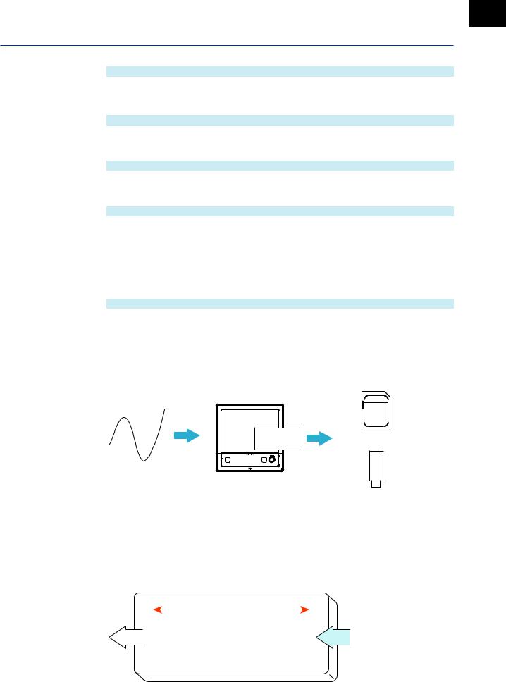
Basic Functions of the GX/GP
GX10/GP10
|
Recording Interval (Trend interval) |
100ms2 |
200ms2 |
500ms2 |
1s2 |
2s2 |
3s3 |
|
Time corresponding to one dot (ms) |
1 |
2 |
5 |
10 |
20 |
50 |
|
Speed of waveform movement |
653400 |
326700 |
130680 |
65340 |
32670 |
13068 |
|
(approximation in mm/h) |
||||||
|
Recording Interval (Trend interval) |
5s1 |
10s1 |
15s |
30s |
1min |
|
|
Time corresponding to one dot (s) |
0.1 |
0.2 |
0.5 |
1 |
2 |
|
|
Speed of waveform movement |
6534 |
3267 |
1307 |
653 |
327 |
|
|
(approximation in mm/h) |
||||||
|
Recording Interval (Trend interval) |
2min |
5min |
10min |
15min |
20min |
|
|
Time corresponding to one dot (s) |
4 |
10 |
20 |
30 |
40 |
|
|
Speed of waveform movement |
163 |
65 |
33 |
22 |
16 |
|
|
(approximation in mm/h) |
||||||
|
Recording Interval (Trend interval) |
30min |
1h |
2h |
4h |
10h |
|
|
Time corresponding to one dot (s) |
60 |
120 |
240 |
480 |
1200 |
|
|
Speed of waveform movement |
11 |
5.4 |
2.7 |
1.4 |
0.5 |
|
|
(approximation in mm/h) |
||||||
|
1 50 dots per division |
||||||
|
2 100 dots per division |
||||||
|
3 60 dots per division |
Related Setup Items
|
Item |
Reference |
|
Trend interval [/div] (display data) |
→page 1-110 |
|
Recording interval (event data) |
→page 1-125 |
Saving
Data files that are divided at a specific time interval (saving interval) and held in the internal memory are automatically saved to an SD memory card (when auto save is set to On). Data files can also be exported to USB flash memory.
Auto save or manual save
SD memory card
manual save
USB flash memory
Media FIFO Function
If not enough free space is available when saving a new data file to the SD memory card, files are deleted in order from the oldest data update date/time to save the new file. This operation is referred to as FIFO (first in first out).
When saving the data files automatically, you can save the data so that the most recent data files are constantly retained in the SD memory card. This method allows you to use the GX/ GP continuously without having to replace the SD memory card.
|
Old |
Update date |
New |
||||||||||||
|
Deleted |
Saved |
|||||||||||||
|
File 1 |
File 2 |
File 3 |
File 4 |
|||||||||||
|
Medium |

Basic Functions of the GX/GP
Related Setup Items
|
Item |
Reference |
|
Saving interval |
→page 1-125 |
|
Auto save |
→page 1-143 |
|
Media FIFO |
Data Utilization
Measurement data files can be loaded into the standard software (Universal Viewer) to display trend waveforms and values.
Moreover, data values at the cursor position can be read, statistics (maximum, minimum, P-P, average, rms) can be calculated, and so forth.
The loaded data can be converted into Excel or text format to be analyzed with other software applications or used in other ways.
Control
By installing a PID Control Module (GX90UT), you can perform PID control of up to 20 loops (up to 6 loops for the GX10/GX20-1/GP10/GP20-1). In addition to control loop monitoring and the control group screen for convenient operation, adjustment using the tuning screen is available.
Adding the /PG option to the GX/GP main unit allows 99 patterns (up to 99 segments per pattern) of program patterns to be stored in the main unit. Further, up to 32 time events and 32 PV events can be set for each segment.
![]()
Chapter 1 Configuring the GX/GP and Viewing the Settings
Setup Guide (Read this first)
GX/GP Setup Procedure
To use the GX/GP, follow the procedure below to configure it.
Configuration flowchart
|
1 |
Set the measurement mode. |
|
2 |
Make the main unit recognize the modules. |
|
|
(Reconfigure the GX/GP.) |
||
|
3 |
Assign channel displays. |
||||
|
Assign automatically |
Assign manually |
||||
Initialize
|
4 |
Set the date and time.1 |
Set the measurement mode according to the measurement conditions.
 Operation: 1.29.3, “Setting the Measurement Mode”
Connected expandable I/O, GM sub unit, and installed modules are identified, and the system is reconfigured. If you change the system configuration, you need to reconfigure.
 Operation: 1.29.4, “Reconfiguring the GX/GP”
To assign channel displays (display group settings) automatically, initialize.
To assign them manually, do it in “Configure settings.”
Channel displays are assigned automatically along with initialization.
 Operation: 1.29.1, “Initializing the Settings and the Internal Memory”
1 If you need to set the time zone or Daylight Saving Time (DST) or both, do so before setting the date and time.
Configure the GX/GP settings.
 See the various settings from section 1.1.
1
Settings the Viewing and GX/GP the Configuring
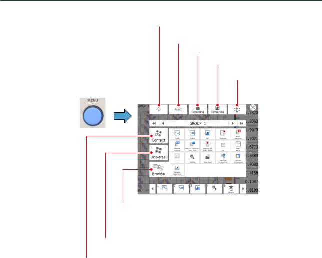
Setup Guide (Read this first)
Menu Screen
 Shows the standard (home) screen.
A screen of your choice can be assigned to the standard screen.
 Ejects storage media (SD, USB).
 Starts and stops recording.
 Starts, stops, and resets computation.
 Shows the alarm status.
|
MENU key |
You can acknowledge alarms. |
Menu screen
Browse tab
A screen for selecting what items are to be shown.
Select the items to be shown such as the setting menu, measurement data, and various types of information.
Common menu tab
Shows items that can be controlled globally independent of the currently displayed.
Context tab
Shows the items that can be displayed and controlled on the currently displayed screen.
The items vary depending on the displayed screen.
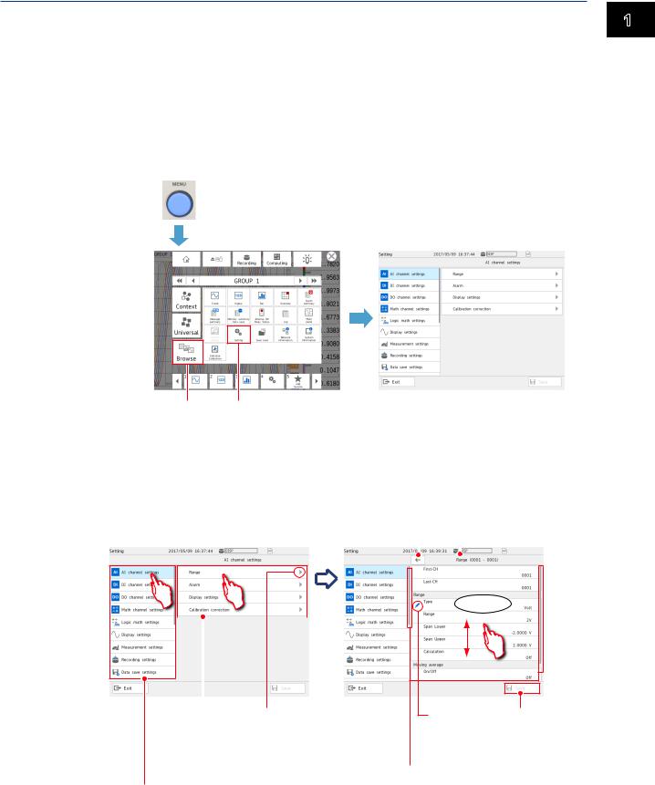
Setup Guide (Read this first)
Setting Screen
Displaying the Setting Screen
1 Press MENU.
The menu screen appears.
2 Tap the Browse tab.
3 Tap Setting.
The Setting screen appears.
1 MENU key
|
Menu screen |
Setting screen |
1
Settings the Viewing and GX/GP the Configuring
2 3
Basic Setting Screen Operations
When you tap an item on the setting menu shown on the left side of the screen, the corresponding setup items appear in the area on the right. When a setup item is layered, tapping the setup item shows the lower layer.
|
Returns to the higher level. |
||||||||
|
Setting screen |
Shows the item name |
|||||||
|
of the current level |
||||||||
Flick
|
Indicates that there |
|||
|
Setup item |
is a lower level. |
||
Shows the setup items for the item selected on the setting menu. When a setup item is layered,
Setting menu group items are displayed. A setting menu appears.
Change mark Saves the settings Appears on items whose
settings have been changed.
Scroll bar display
This appears when there are additional setting menus or setup items outside the screen display.
Flick to show the setting menus and setup items that are hidden from the screen.
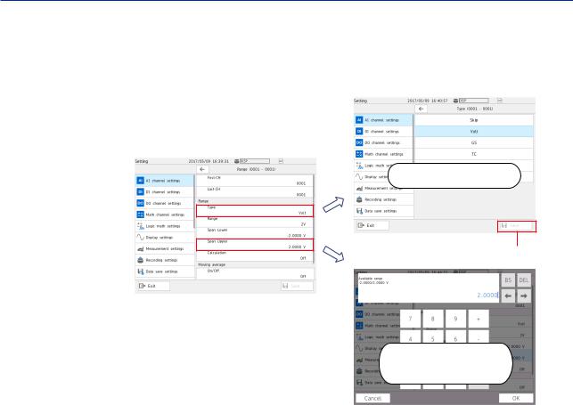
Setup Guide (Read this first)
Types of Settings
There are settings that you choose from a list or those that you enter values or character strings.
For those that you choose from a list, choose a value from the list.
For those that you need to enter a value, set the value using the displayed keyboard. Then, tap Save to save the setting.
Select from the list
Saves settings
Enter from the keyboard

Setup Guide (Read this first)
Basic GX/GP Configuration
Setup Procedure
This section explains the basic GX/GP setup items when the measurement mode is set to Normal.
In an actual setup, settings other than those shown here need to be configured depending on the usage conditions.
In addition, settings and values very depending on the measurement mode.
|
Setup items |
Main settings |
|||
|
1 |
Channel settings of each module |
|||
|
I/O channel settings |
||||
|
• Range |
||||
|
• Alarm |
||||
|
• Display settings |
||||
|
• Calibration correction |
||||
|
2 |
Measurement settings |
|||
|
Measurement settings |
||||
|
• Scan interval |
||||
|
• Module operation mode |
||||
|
• A/D integrate |
||||
|
3 |
Measurement data recording settings |
|||
|
Recording settings |
||||
|
• File type |
||||
|
• Saving interval |
||||
|
• Recording channel |
||||
|
4 |
Measurement data display settings |
|||
|
Display settings |
||||
|
• Trend interval |
||||
|
• Group settings |
||||
|
• Message settings |
||||
|
• Trend settings |
||||
|
• Screen display settings |
||||
|
5 |
Measurement data save settings |
|||
|
Data save settings |
||||
|
• Save directory |
||||
|
• File header |
||||
|
• Data file name |
||||
|
• Media save |
||||
|
• File format |
1
Settings the Viewing and GX/GP the Configuring
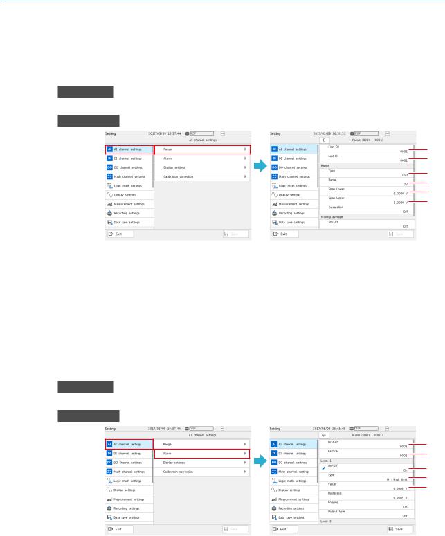
Setup Guide (Read this first)
Basic Setup
1.I/O Channel Settings (AI channel setting example)
The procedure for setting the range, display span (display range), alarm, tag display, and the like of each channel is described below.
Range Setting
Procedure
On the setting menu, tap AI channel settings and then Range.
Description
1
2
3
4
5
6
Set the first channel.1
Set the last channel.1
Set the input type.
Set the range.
Set the low limit (span lower) to be displayed.
Set the high limit (span upper) to be displayed.
1If the settings are the same for multiple channels, you can set a channel range by specifying the first channel and last channel, and configure those channels simultaneously.
Alarm Setting (Example of setting level 1)
Procedure
On the setting menu, tap AI channel settings and then Alarm.
Description
1
2
3
4
5
Set the first channel. Set the last channel.
Specify On to assign an alarm to Level 1.1 Set the alarm type.
Set the alarm value.
1 You can set up to four alarms (Level 1 to 4).
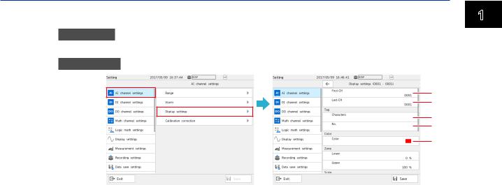
Setup Guide (Read this first)
Display Settings
Procedure
On the setting menu, tap AI channel settings and then Display settings.
Description
1
2
3
4
5
1 Set the first channel.
2 Set the last channel.
3 Set the tag characters.
4 Set the tag number.
5 Set the display color.
Numbers are displayed with higher precedence than characters. When a number is not assigned, the tag characters are displayed. If neither is set, the channel number is displayed.
1
Settings the Viewing and GX/GP the Configuring
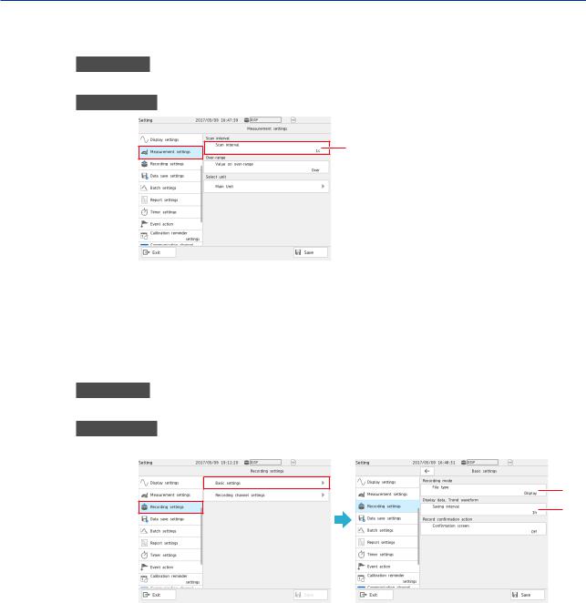
Setup Guide (Read this first)
2.Measurement Settings
Set the scan interval.
Procedure
On the setting menu, tap Measurement settings and then Scan interval.
Description
1
1 Set the scan interval.
3.Recording Settings
Specify the settings for recording measured data.
Set the recording conditions for each file type, display data and event data.
Basic Setup
Procedure
On the setting menu, tap Recording settings and then Basic settings.
Description
When the File Type Is Display Data
1
2
Tap File type and then Display.
Set the interval for saving data files of display data.
The files are divided with the interval specified here.

Setup Guide (Read this first)
When the File Type Is Event Data
1
2
3
4
1 Tap File type and then Event.
2 Set the interval for recording event data.
3 Set the mode for recording event data.
4 Set the measurement data length (per file).
Recording Channel Settings
Procedure
On the setting menu, tap Recording settings and then Recording channel settings.
Description
1
2
3
1
Settings the Viewing and GX/GP the Configuring
Set the channels for recording display data. Set the channels for recording event data.
Set the channels for recording manual sampled data.
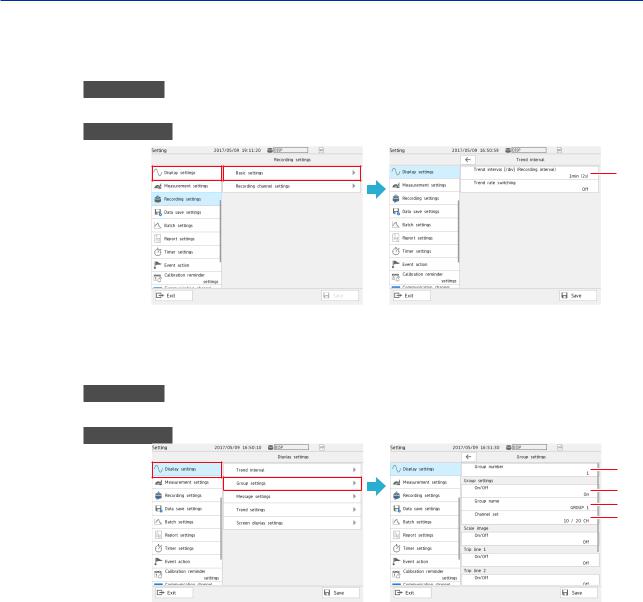
Setup Guide (Read this first)
4.Display Settings
Specify the measured waveform display settings.
Trend Interval Setting
Procedure
On the setting menu, tap Display settings and then Trend interval.
Description
1
1 Set the trend interval [/div].
Group Settings
Procedure
On the setting menu, tap Display settings and then Group settings.
Description
1
2
3
4
Set the number of the group to display.
Set this to On to use the display group of the specified display group number. Assign a group name to the display group.
Set the channels to display in the display group.
![]()
Setup Guide (Read this first)
Message Settings (registering messages)
Procedure
On the setting menu, tap Display settings and then Trend settings.
Description
1
2
1 Set the message number range (in unit of 10 messages) to set (register) messages.
2 Assign a message to each message number.
Trend settings
Procedure
On the setting menu, tap Display settings and then Trend settings.
Description
1
2
3
4
1 Set the direction to display waveforms (direction in which the waveforms flow).
2 Set this to On to display new waveforms after clearing the previous waveforms when recording is started.
3 Set the line width of displayed waveforms to Thick, Normal, or Thin.
4 Set the number of grids (4 to 12).
1
Settings the Viewing and GX/GP the Configuring

Setup Guide (Read this first)
Screen Display Settings
Procedure
On the setting menu, tap Display settings and then Screen display settings.
Description
1
1 Set the bar graph display direction.
5.Data Save Settings
Specify the settings for saving measurement data to files.
Procedure
On the setting menu, tap Data save settings.
Description
2
3
4
5
6
Set the directory to save data files.
Set the data file header.
Set the structure of data file names.
Set the name of the data files.
Set whether to save automatically or manually to the external storage medium. Auto saving is recommended. To use manual saving, set this to Off.
6 Set the media FIFO.
If set to On, if new files cannot be saved to the external storage medium, files will be overwritten from the oldest file. If you do not want the files to be overwritten, select
Off.
 For details on media FIFO, see page 1-143 in section 1.14.2, “Setting the Save Method to Media (Auto save or manual save) and Media FIFO”.
7 Set the format of the files to be saved to the external storage medium.

What Do You Want to Configure?
1. Measurement Source
You can assign DC voltages, thermocouples, RTDs, and on/off signals based on contacts and voltages to channels to take measurements. The measurement section is modular, so it can be expanded as necessary.
Input signals are sampled at the scan interval and converted to measured values through A/D conversion.
Setting Measurement Conditions (Setting menu: Measurement settings, Dual interval settings)
|
Item |
Reference |
|
Setting the scan interval |
→page 1-119 |
|
Setting the operation mode of a module (AI module: 2ch mode/10ch mode |
|
|
(universal, current (mA)), 2ch mode/6ch mode (4-wire RTD/resistance), |
→page 1-120 |
|
DI module: normal/remote) |
|
|
Setting the A/D integration time of an AI module (analog input module) |
→page 1-122 |
|
Setting noise rejection (high-speed AI module and PID control module) |
→page 1-123 |
|
Setting how to detect over-range values |
→page 1-120 |
|
Setting the burnout criteria |
→page 1-124 |
|
When the measurement mode is set to dual interval (Dual interval settings) |
|
|
Item |
Reference |
|
Setting the scan interval (measurement group 1, measurement group 2) |
→page 1-137 |
|
Setting the module scan intervals |
→page 1-138 |
2. Configuring Measurement Channels
You can set measurement conditions for each channel based on the input. You can calculate the difference between two input values or convert input values to measurement values with units that suit your purpose.
Alarms can be generated when measured data exceeds or goes below specified values. Information that indicates alarm occurrence can be shown on the screen. Digital output channels (DO channels) can be used to transmit relay contact signals.
You can change channel colors and assign tags to channels.
Configuring Analog Input Channels (Setting menu: AI channel settings, AI (mA) channel)
Source module: Analog input module (GX90XA)
Setting the Range
|
Item |
Reference |
|
|
Input range (type, range, span lower, span upper) |
||
|
Performing input calculation (delta, linear scaling, square root) |
||
|
Taking the moving average of input values (suppressing noise) |
→page 1-27 |
|
|
Setting the reference junction compensation mode (internal, external) |
||
|
Setting burnout detection |
||
|
Adding bias to input values |
||
|
Setting the first-order lag filter (high-speed AI module) |
→page 1-32 |
Setting Alarms
|
Item |
Reference |
|
Setting alarms (type, value, hysteresis, logging, output, alarm delay) |
→page 1-35 |
1
Settings the Viewing and GX/GP the Configuring

What Do You Want to Configure?
Setting the Display
|
Item |
Reference |
|
Setting channel tags (characters, No.) |
|
|
Setting display colors |
→page 1-40 |
|
Dividing display areas to prevent waveform overlap (setting zones) |
|
|
Setting the scale display position and divisions |
|
|
Setting the base position and divisions of the bar graph display |
|
|
Enabling the partial expanded display |
→page 1-40 |
|
→page 1-114 |
|
|
Displaying the color scale band (band area (in, out), color) |
→page 1-40 |
|
Displaying alarm point marks (mark kind, alarm mark color) |
|
|
Displaying on/off (1/0) signals with characters (when the range type is DI) |
Performing Calibration Correction
|
Item |
Reference |
|
Performing calibration correction (linearizer approximation, linearizer bias, |
→page 1-53 |
|
correction factor) |
Configuring Digital Input Channels (Setting menu: DI channel settings)
Source module: Digital input module (GX90XD)
|
Digital input/output module (GX90WD) |
||
|
Setting the Range |
||
|
Item |
Reference |
|
|
Setting the input range (type, span lower, span upper) |
→page 1-57 |
|
|
Performing input calculation (delta, linear scaling) |
||
|
Setting Alarms |
||
|
Item |
Reference |
|
|
Setting alarms (type, value, hysteresis, logging, output type, alarm delay) |
→page 1-58 |
|
|
Setting the Display |
||
|
Item |
Reference |
|
|
Setting channel tags (characters, No.) |
||
|
Setting Display Colors |
||
|
Dividing display areas to prevent waveform overlap (setting zones) |
→page 1-60 |
|
|
Setting the scale display position |
||
|
Setting the base position and divisions of the bar graph display |
||
|
Displaying alarm point marks (mark kind, alarm mark color) |
||
|
Displaying on/off (1/0) signals with characters |
Configuring Pulse Input Channels (Setting menu: Pulse input channel settings)
Setting the Range
Source module: Pulse input module (GX90XP)
|
Item |
Reference |
|
Input range (type, range, chattering filter, span lower, span upper) |
→page 1-63 |
|
Performing input calculations (delta, linear scaling) |
|
|
Taking the moving average of input values (suppressing noise) |
Setting Alarms
|
Item |
Reference |
|
Setting alarms (type, value, hysteresis, logging, output, alarm delay) |
→page 1-65 |

What Do You Want to Configure?
Setting the Display
|
Item |
Reference |
|
|
Setting channel tags (characters, No.) |
||
|
Setting display colors |
→page 1-66 |
|
|
Dividing display areas to prevent waveform overlap (setting zones) |
||
|
Setting the scale display position and divisions |
||
|
Setting the base position and divisions of the bar graph display |
||
|
Enabling the partial expanded display |
→page 1-40 |
|
|
→page 1-114 |
||
|
Displaying the color scale band (band area (in, out), color) |
→page 1-66 |
|
|
Displaying alarm point marks (mark kind, alarm mark color) |
||
Configuring Analog Output Channels (Setting menu: AO channel settings)
Source module: Analog output module (GX90YA)
Setting the Range
|
Item |
Reference |
|
|
Setting the range (type, range, span lower, span upper) |
||
|
Setting the reference channel (channel type, CH number) |
→page 1-70 |
|
|
Setting preset values |
||
|
Setting preset actions (at power on, on error, during stop conditions) |
Setting the Display
|
Item |
Reference |
|
Setting channel tags (characters, No.) |
|
|
Setting display colors |
→page 1-74 |
|
Dividing display areas to prevent waveform overlap (setting zones) |
|
|
Setting the scale display position and divisions |
|
|
Setting the base position and divisions of the bar graph display |
Configuring Digital Output Channels (Setting menu: DO channel settings)
Source module: Digital output module (GX90YD) Digital input/output module (GX90WD)
Setting the Range
|
Item |
Reference |
|
Setting the range (type, span lower, span upper, unit) |
→page 1-76 |
|
Setting the action (energize/de-energize, action (and, or, reflash), hold, relay action |
|
|
on ACK) |
Setting the Display
|
Item |
Reference |
|
|
Setting channel tags (characters, No.) |
||
|
Setting Display Colors |
||
|
Dividing display areas to prevent waveform overlap (setting zones) |
→page 1-80 |
|
|
Setting the scale display position and divisions |
||
|
Setting the base position and divisions of the bar graph display |
||
|
Displaying on/off (1/0) states with characters |
1
Settings the Viewing and GX/GP the Configuring

What Do You Want to Configure?
3. Displaying Measured Data
Measured data acquired in the internal memory can be displayed on the operation screen as trend waveforms, values, or bar graphs. In addition, in accordance with the application or the situation at the actual site, measured data can be displayed on a monitor screen (custom display (/CG option)) that the user designs using DXA170 DAQStudio. A list of alarm conditions can be displayed.
Custom display

What Do You Want to Configure?
Configuring the display settings (Setting menu: Display settings)
Setting the Trend Interval
|
Item |
Reference |
|
|
Setting the trend interval (/div) |
→page 1-110 |
|
|
Using the second trend interval |
||
Configuring the Display
|
Item |
Reference |
|
|
Setting the bar graph display direction, LCD brightness, view angle (GX10/GP10 |
||
|
only) and backlight saver |
||
|
Setting the monitor background color, scroll time, and jump default display |
→page 1-117 |
|
|
Setting the first weekday of the calendar display |
||
|
Enabling changes to each value (alarm values, DO output operation) from the |
||
|
monitor display |
Setting Trend Display Conditions
|
Item |
Reference |
|
|
Setting the trend display direction, trend line, and grid |
||
|
Clearing displayed waveforms when recording starts |
||
|
Configuring the trend scale settings (digit, value indicator, digit of mark) |
→page 1-114 |
|
|
Enabling the trend partial expanded display |
||
|
Setting the message writing feature for power failures and trend interval changes |
||
|
(power-fail message, change message) |
Setting Display Groups
|
Item |
Reference |
|
|
Setting group names and channels |
||
|
Displaying the scale using the scale image you created |
→page 1-111 |
|
|
Displaying lines at specified positions in the waveform display range (trip line) |
||
|
(trend display) |
Setting messages
|
Item |
Reference |
|
Setting messages |
→page 1-113 |
4. Saving Data
Measured data is recorded to internal memory. Recorded measurement data can be automatically saved to an SD memory card or retrieved on a USB flash memory device.
AI channels, DI channels, DO channels, math channels, communication channels as well as information such as reports, alarms, messages, and time stamps are saved.
SD memory card
USB flash memory
1
Settings the Viewing and GX/GP the Configuring

What Do You Want to Configure?
Setting Recording Conditions (Setting menu: Recording settings, Dual interval settings)
|
Item |
Reference |
|
|
Setting the type of recording data (display data, event data) |
||
|
Setting the interval for saving data files of display data |
||
|
Setting the recording interval of event data, recording mode (free, trigger), and |
→page 1-125 |
|
|
recording time. |
||
|
Setting the record confirmation screen (record start, record stop) display for when |
||
|
the START/STOP key is used |
||
|
Setting the measurement data (display data, event data, manual sampled data) |
→page 1-133 |
|
|
channels to record (IO channel, math channnel, communication channel) |
||
|
When the measurement mode is set to dual interval (Dual interval settings) |
||
|
Item |
Reference |
|
|
Setting the recording interval of event data, recording mode (free, trigger), and |
→page 1-138 |
|
|
recording time. |
||
|
Setting the channels on which to record event data (Measurement group 1, |
||
|
measurement group 2) and manual sampled data (I/O channel, Math channel, |
→page 1-140 |
|
|
Communication channel) |
Setting Conditions for Saving Data Files (Setting menu: Data save settings)
|
Item |
Reference |
|
Setting the data file’s save directory, file header, and data file name |
→page 1-141 |
|
Setting how to save data files to the storage medium (auto save, manual save) |
|
|
Configure the GX/GP so that when there is no free space on the storage medium |
→page 1-143 |
|
during auto saving, files are deleted in order starting with the oldest file and new |
|
|
files are saved. (Media FIFO) |
|
|
Setting the file format of display data and event data (binary, text) |
→page 1-147 |
Setting the Batch Function (Setting menu: Batch settings)
|
Item |
Reference |
|
Enabling the batch function and setting the lot number digits and auto |
|
|
incrementation |
→page 1-148 |
|
Setting batch text |
5. Event Action Function
The event action function is used to execute a specified action when certain events occur. For example, you can use the event action function to do the following:
a)Start recording when the remote control input (DI channel) turns on.
b)Record a message when an alarm occurs.
c)Create a record file at a specific time.
Configuring the Event Action Function (Setting menu: Event action)
|
Item |
Reference |
|
Configuring the event action |
→page 1-162 |
|
Event action examples |
→page 1-170 |
Setting Timers (Setting menu: Timer settings)
|
Item |
Reference |
|
Setting timers (type (relative timer, absolute timer), interval, action on math start, |
→page 1-159 |
|
reference time) |
|
|
Setting the match time timer (type, timer match condition, timer action) |
→page 1-160 |

What Do You Want to Configure?
6. Computation and Report Functions (/MT option)
You can use math channels to write expressions that refer to measured data and math data as variables.
The maximum or minimum value in measured data recorded over a day or the sum of the measured data recorded over a day can be recorded.
Setting Math Channels (/MT option) (Setting menu: Math channel settings)
Setting Expressions
|
Item |
Reference |
|
Setting expressions (expression, decimal place, span (upper, lower), unit) |
→page 1-84 |
|
Setting the TLOG computation (timer type, timer No., sum scale, reset) |
|
|
Performing rolling average |
|
|
How to write expressions |
→page 1-91 |
|
Setting constants to use in computation |
→page 1-105 |
Setting Alarms
|
Item |
Reference |
|
Setting alarms (type, value, hysteresis, logging, output, alarm delay) |
→page 1-101 |
Setting the Display
|
Item |
Reference |
|
|
Setting channel tags (characters, No.) |
||
|
Setting display colors |
→page 1-102 |
|
|
Dividing display areas to prevent waveform overlap (setting zones) |
||
|
Setting the scale display position and divisions |
||
|
Setting the base position and divisions of the bar graph display |
||
|
Enabling the partial expanded display |
→page 1-102 |
|
|
→page 1-114 |
||
|
Displaying the color scale band (band area (in, out), color) |
→page 1-102 |
|
|
Displaying alarm point marks (mark kind, alarm mark color) |
||
Setting Constants
|
Item |
Reference |
|
Setting constants to use in computation |
→page 1-105 |
|
Setting Variable Constants to Use in Computation |
→page 1-106 |
Setting the Computation Operation
|
Item |
Reference |
|
Setting error displays (+over, –over) |
→page 1-83 |
|
Starting recording and computation simultaneously |
|
|
Setting how to process computation overflow data |
Setting Internal Switches
|
Item |
Reference |
|
Setting internal switch types (alarm, manual), action (and, or) |
→page 1-208 |
Configuring the Report Function (/MT option) (Setting menu: Report settings)
|
Item |
Reference |
|
Setting the report type, creation time, data type, file type (combine, separate), and |
→page 1-151 |
|
report template output (Excel, PDF, printer) |
|
|
Setting the PDF electronic signature |
→page 1-151 |
|
Setting the channels to output reports |
→page 1-154 |
|
Using the report template function |
→page 1-156 |
1
Settings the Viewing and GX/GP the Configuring

What Do You Want to Configure?
Configuring Logic Math Settings (/MT option) (Setting menu: Logic math settings)
|
Item |
Reference |
|
Configuring Logic Math (Output, calculation expression) |
→page 1-107 |
7. Configuring System Settings
You can change the displayed language, date and time, network printer settings, operation sound, warning sound, etc.
Configuring System Settings (Setting menu: System settings)
Setting the Displayed Language, Temperature unit and Decimal Point Type
|
Item |
Reference |
|
Setting the displayed language, Temperature unit and decimal point type (point, |
→page 1-203 |
|
comma) |
Setting the Date and Time, Time Zone, Time Adjustment Function, and DST
(Daylight saving time)
|
Item |
Reference |
|
Setting the date and time |
→page 1-26 |
|
Setting the time offset from Greenwich Mean Time (time zone) |
→page 1-205 |
|
Setting the function that gradually adjusts the time when the time is changed in the |
|
|
middle of recording |
|
|
Setting the date format |
→page 1-203 |
|
Setting the DST (daylight saving time) |
→page 1-205 |
Setting the FAIL Output and Instrument Information Output (/FL option)
|
Item |
Reference |
|
Setting the FAIL output and instrument information output |
→page 1-209 |
Configuring the Printer
|
Item |
Reference |
|
|
Setting the printer output conditions (IP address, paper size, paper orientation, |
→page 1-211 |
|
|
resolution, number of copies, snapshot, fit to page size) |
||
Configuring the Sound and LED Settings
|
Item |
Reference |
|
|
Enabling touch and warning sounds |
→page 1-212 |
|
|
Displaying alarm status with LEDs |
||
Setting Instrument Tags
|
Item |
Reference |
|
Setting the GX/GP’s instrument tag and instrument tag No. |
→page 1-212 |
Setting Comments to Setting Files
|
Item |
Reference |
|
Setting comments to setting files |
→page 1-213 |
Setting USB Input Devices
|
Item |
Reference |
|
Setting USB input devices (keyboard type, execution of communication commands |
→page 1-214 |
|
using bar codes) |
Setting the Alarm Basic Operation (Setting menu: System settings)
|
Item |
Reference |
|
Setting the interval for calculating the rate of change for rate-of-change alarms |
|
|
(decrease, increase) |
→page 1-204 |
|
Setting the alarm display hold/nonhold and individual alarm ACK operation |
![]()
What Do You Want to Configure?
8. Security Function
You can set the lock function to prohibit tap operations and also allow only registered users to operate the GX/GP.
Configuring the Security Function (Setting menu: Security settings)
Basic Settings
|
Item |
Reference |
|
Applying security features to tap operation and communication (login, ope lock) |
→page 1-218 |
|
Automatically logging out users when there is no tapping activity for a specified |
|
|
time (login) |
|
|
Setting items to lock the operation of (ope lock) |
→page 1-219 |
|
Registering users (administrators, users) (login) |
→page 1-222 |
|
Setting user limitation conditions (login) |
→page 1-223 |
9. Communication Function
You can use the communication interface (Ethernet or serial) to perform the following operations.
•Configure and operate the GX/GP.
•Monitor the GX/GP measured data.
•Retrieve files on the external storage medium of the GX/GP.
•Automatically transfer measurement data files to an FTP server.
•Monitor and configure the GX/GP through a Web browser.
•Transmit e-mails to specified addresses when alarms and other events occur.
•Read data from a device connected to the network or write GX/GP data.
Control operation, configure, and monitor measured data
View on a Web browser
Ethernet
|
Read/write data |
Automatically transfer |
||||||||||||||||
|
measurement data files |
|||||||||||||||||
FTP Server
Configuring the Ethernet Communication Function (Setting menu: Communication (Ethernet) settings)
Configuring Basic Settings
|
Item |
Reference |
|
Automatically obtaining the IP address (DHCP) or setting it manually |
|
|
Automatically obtaining the DNS server addresses or manually setting them |
|
|
(primary, secondary, domain suffixes) |
→page 1-180 |
|
Setting the host information |
|
|
Registering the host name |
Configuring the FTP Client Function (File transfer from the GX/GP using FTP)
|
Item |
Reference |
|
|
Enabling the FTP client function and setting the files to transfer |
||
|
Delaying data transfers to the FTP server (transfer wait time) |
→page 1-182 |
|
|
Setting SSL encryption on data sent via FTP |
||
|
Setting the destination server (primary, secondary) |
1
Settings the Viewing and GX/GP the Configuring

What Do You Want to Configure?
Configuring the SMTP Client Function (E-mail transmission)
|
Item |
Reference |
|
|
Setting the user authentication method |
||
|
Setting SSL encryption on data sent via SMTP |
→page 1-184 |
|
|
Setting the SMTP server |
||
|
Setting the POP3 server |
||
|
Setting the e-mail transmission conditions (recipients, subject, header, cause, etc.) |
→page 1-185 |
Configuring the SNTP Client Function (Time synchronization via communication)
|
Item |
Reference |
|
|
Configuring the SNTP server |
→page 1-188 |
|
|
Setting the query operation (interval, timeout, time adjust on start action) |
||
Configuring the Modbus Client Function (External device connection via
Modbus protocol; /MC option)
|
Item |
Reference |
|
|
Enabling the Modbus client function and configuring basic settings (communication |
||
|
interval, recovery action, keep connection) |
→page 1-189 |
|
|
Configuring the destination server |
||
|
Setting the commands to transmit (type, data type, register, etc.) |
Limiting the Connection to the Modbus Server (GX/GP)
|
Item |
Reference |
|
Limiting the connection to the Modbus server (GX/GP) |
→page 1-193 |
Configuring the Operation of the Server Functions
|
Item |
Reference |
|
Setting the operation of the server functions (keep alive, timeout, FTP server output |
→page 1-192 |
|
directory format, Modbus server delay response) |
Setting the Server Functions to Use
|
Item |
Reference |
|
Setting the server functions to use (FTP, HTTP, SNTP, MODBUS, GENE) |
→page 1-194 |
|
Setting SSL encryption on data sent and received by the FTP server and HTTP |
|
|
server |
|
|
Setting DARWIN compatible communication |
Configuring the Serial Communication Function (/C2 and /C3 options) (Setting menu: Communication (serial) settings)
Configuring Basic Settings
|
Item |
Reference |
|
|
Configuring the serial communication function (normal, Modbus master, Modbus |
||
|
slave, execution of communication commands using bar codes) |
→page 1-198 |
|
|
Setting communication conditions (baud rate, parity, handshake, etc.) |
||
|
Setting auto logout |
Configuring the Modbus Master Function
|
Item |
Reference |
|
Configuring the Modbus master function (communication interval, communication |
→page 1-200 |
|
timeout, gap between messages, recovery action) |
|
|
Setting the Modbus master transmission commands (type, data type, register, etc.) |
→page 1-201 |

What Do You Want to Configure?
Setting Communication Channels (/MC option) (Setting menu: Communication channel settings)
|
Item |
Reference |
|
Setting communication channels (decimal place, span (upper, lower), unit) |
→page 1-173 |
|
Replacing values with preset values when communication data is not updated for a |
|
|
specified time period (watchdog timer function) |
Setting Alarms
|
Item |
Reference |
|
Setting alarms (type, value, hysteresis, logging, output, alarm delay) |
→page 1-175 |
Setting the Display
|
Item |
Reference |
|
|
Setting channel tags (characters, No.) |
||
|
Setting display colors |
→page 1-176 |
|
|
Dividing display areas to prevent waveform overlap (setting zones) |
||
|
Setting the scale display position and divisions |
||
|
Setting the base position and divisions of the bar graph display |
||
|
Enabling the partial expanded display |
→page 1-176 |
|
|
→page 1-114 |
||
|
Displaying the color scale band (band area (in, out), color) |
→page 1-176 |
|
|
Displaying alarm point marks (mark kind, alarm mark color) |
||
10. Miscellaneous
Saving Settings to External Storage Media (Save settings)
|
Item |
Reference |
|
Saving setting parameters |
→page 1-238 |
|
Saving scale images |
→page 1-239 |
|
Saving report templates (/MT option) |
→page 1-241 |
|
Saving program patterns |
→page 1-244 |
|
Saving setting parameters, scale images, report templates, trusted certificates |
→page 1-242 |
|
(release number 2 and later), custom display (/CG option) (release number 2 and |
|
|
later), and program pattern (/PG option) (release number 4 and later) at once |
|
|
Saving trusted certificates |
→page 1-242 |
|
Saving custom displays (/CG option) |
→page 1-242 |
Loading Setting Files into the GX/GP from External Storage Media (Load settings)
|
Item |
Reference |
|
Loading setting parameters |
→page 1-224 |
|
Loading scale images and clearing them from the screen |
→page 1-226 |
|
Loading report templates (/MT option) |
→page 1-228 |
|
Loading and deleting program patterns |
→page 1-234 |
|
Loading setting parameters, scale images, report templates, trusted certificates |
→page 1-236 |
|
(release number 2 and later), custom display (/CG option) (release number 2 and |
|
|
later), program pattern (/PG option) (release number 4 and later), and multi batch |
|
|
settings (/BT option) (release number 3 and later) at once |
|
|
Listing files that are on the external storage medium |
→page 1-247 |
|
Formatting the external storage medium |
→page 1-248 |
1
Settings the Viewing and GX/GP the Configuring

What Do You Want to Configure?
Setting the Measurement Mode
|
Item |
Reference |
|
Setting the Measurement Mode |
→page 1-254 |
Initializing, Reconfiguring, and Adjusting the Touch Screen (Initialization and reconfiguration)
|
Item |
Reference |
|
Initializing the settings and internal memory |
→page 1-249 |
|
Reconfiguring the GX/GP |
→page 1-256 |
|
Adjusting the Touch Screen |
→page 5-18 |
Creating Keys, Managing Certificates, Viewing Certificates, and Removing
Certificates
|
Item |
Reference |
|
Enabling the encryption function |
→page 1-258 |
|
Creating keys |
→page 1-258 |
|
Configuring certificate management (creating self-signed certificates, creating |
→page 1-259 |
|
certificate signature requests (CSRs), installing certificates, and installing |
|
|
intermediate certificates) |
|
|
Viewing certificate details and removing certificates |
→page 1-262 |
Using the Aerospace Heat Treatment (/AH option) (Release number 3 and later)
|
Item |
Reference |
|
Setting the calibration reminder |
→page 1-272 |
|
Setting calibration correction (linearizer approximation, linearizer bias, correction |
→page 1-53 |
|
factor (release number 3 and later)) |

Quick Setting Function (GP10/GP20, Release number 3 (Version 3.02) and later)
In Quick setting, a minimal setup menu for data collection is displayed.
Quick setting allows you to collect data quickly.
|
Display example of the quick settings |
Display example of the standard settings |
Switching between Standard Settings and Quick Settings
Press MENU, and tap the Browse tab and then Setting. Tap the Quick setting tab or
Standard setting tab to switch between the two modes.
|
Tab |
Function |
|
Quick setting |
The display is switched from standard settings to quick settings. |
|
When switched to quick settings, the characters “Quick setting” turns |
|
|
blue. |
|
|
Standard setting |
The display is switched from quick settings to standard settings. |
|
When switched to standard settings, the characters “Standard setting” |
|
|
turns blue. |
•If the GP10/GP20 is shut down when quick settings are displayed, the next time it is started, quick settings will be displayed.
Note
•If items whose settings have been changed are unsaved, unless you cancel the settings, you will not be able to switch between standard settings and quick settings. Save the settings before switching between the two.
•If the advanced security function (/AS) is enabled (On), quick settings are disabled (Quick setting and Standard setting are not displayed).
Quick Setting Display
The following items are displayed in quick settings.
|
Display item |
Description |
|
IO channel > Range |
Configure settings related to the range of each I/O channel. |
|
Input channel > Alarm |
Configure settings related to the alarm of each Input channel. |
|
Display settings |
Set the trend interval. This does not appear when the file type is set to |
|
Event (default value). |
|
|
Recording settings |
Set the save interval of display data, recording interval of event data, |
|
and so on. |
|
|
Dual interval |
Configure settings related to recording by measurement groups (when |
|
the measurement mode is set to dual interval). |
For details on the settings, see the description of the settings explained in this chapter.
1
Settings the Viewing and GX/GP the Configuring

1.1Setting the Date and Time
Set the date and time.
If you need to set the time zone or DST (Daylight Saving Time) or both, do so before setting the date and time.
 See page 1-205 in section 1.23.4, “Setting the Time Zone, Gradual Time Adjustment, and
Daylight Saving Time”
Path
GX/GP:MENU key > Universal tab > Date/Time setting
Web application: Operation tab > Date/Time setting
Description
|
Setup Item |
Selectable Range or Options |
Default Value |
|
Date |
2001 to 2035 |
— |
|
Time |
— |
— |
Date/time Settings
Set the date using the calendar and the time.
Procedure
1 Tap the Date tab. Use the switch icons to set the Year and Month.
The year and month are set.
 Date tab
 Time tab
Switch the year Switch the month
The content of the screen varies depending on the Date format setting.
 See page 1-203 in section 1.23.1, “Setting the Display Language, Temperature Unit, Decimal Point Type, and Date Format”
2 Tap the Time tab. Enter the time using the keyboard, and tap OK.
The time is set.
Operation complete

1.2Configuring AI Channels (Analog (including DI) input) channels and AI (mA) channels
Set the AI channels’ and AI (mA) channels’ input range, alarm, display, and calibration correction.
Set the necessary setup items in order from the top.
1.2.1Setting the Range
Path
GX/GP: MENU key > Browse tab > Setting > Setting menu AI channel settings or AI (mA) channel settings > Range
Web application: Config. tab > AI channel settings or AI (mA) channel settings > Channel range (display example: 0001-0010) > Range
Hardware configurator: AI channel settings or AI (mA) channel settings > Channel range (display example: 0001-0010) > Range
Description
|
Setup Item |
Selectable Range or Options |
Default Value |
|
First-CH |
AI channel |
— |
|
Last-CH |
AI channel |
— |
First-CH, Last-CH
Set the target channels. The channels that you can specify appear depending on the module configuration.
Range
|
Setup Item |
Selectable Range or Options |
Default Value |
|
Type 6 |
Skip, Volt4/GS (general signal)4/TC |
Volt |
|
(thermocouple)4/RTD (resistance |
||
|
temperature detector)1, 4/DI (contact, |
||
|
voltage level)4, current (0 to 20 mA)3, |
||
|
GS (4 to 20 mA) (general signal)3, |
||
|
resistance7 |
||
|
Range4 |
See “Range Details.” |
See “Range Details.” |
|
Span Lower 6 |
Numeric value (depends on the range) |
–2.0000 |
|
Span Upper 6 |
Numeric value (depends on the range) |
2.0000 |
|
Calculation 6 |
Off, Delta, Linear scaling, Square root, |
Off |
|
log input5, pseudo-log input5, linear-log |
||
|
input5 |
||
|
Reference channel 2 |
Number (I/O channel number) |
— |
1Cannot be specified for the electromagnetic relay type (Type suffix code -T1) or low withstand voltage relay type (Type suffix code -L1) analog input module.
2Appears when Calculation is set to Delta.
3Appears for AI (mA) channels.
4Does not appear for AI (mA) channels.
5Appears on models with the log scale (/LG) option when the range type is Volt.
6The default values of AI (mA) channels are GS for Type, 4.000 for Span Lower, 20.000 for Span
Upper, and Linear scaling for Calculation.
7Appears for 4-wire RTD/resistance type channels
Type
Set the input signal type.
|
Options |
Description |
|
Skip |
Not measured. |
|
Volt, GS, TC, RTD, DI, |
Input type. Represents DC voltage, GS (0.4-2V, 1-5V inputs), thermocouple, |
|
current (0 to 20 mA), |
RTD, ON/OFF input, current (0 to 20 mA), GS (4 to 20 mA general signal), and |
|
GS (4 to 20 mA), |
resistance, respectively. |
|
Resistance |
1
Settings the Viewing and GX/GP the Configuring

1.2 Configuring AI Channels (Analog (including DI) input) channels and AI (mA) channels
Note 
For the channels in which you are not using an electromagnetic relay type module, set the range type to Skip.
Range
Set the input type range.
Range Details
|
Type |
Range |
Selectable Range |
Default Value |
Notes |
|
Volt |
20mV |
–20.000 mV to 20.000 mV 2V |
||
|
(DC voltage) |
60mV |
–60.00 mV to 60.00 mV |
||
|
200mV |
–200.00 mV to 200.00 mV |
|||
|
1V |
–1.0000 V to 1.0000 V |
|||
|
2V |
–2.0000 V to 2.0000 V |
|||
|
6V |
–6.000 V to 6.000 V |
|||
|
20V |
–20.000 V to 20.000 V |
|||
|
50V |
–50.00 V to 50.00 V |
|||
|
100V |
–100.00V to 100.00V |
For the high-speed |
||
|
universal type |
||||
|
DI |
LVL (level) |
On (1)/off (0) (voltage) |
LVL |
On: 2.5 V or higher |
|
Off: 2.3 V or less |
||||
|
DI (contact) |
On (1)/off (0) (contact) |
|||
|
GS |
0.4-2V |
0.3200 V to 2.0800 V |
1 — 5 V |
|
|
(general signal) |
1-5V |
0.800 V to 5.200 V |
||
|
DC current |
— |
0.000 mA to 20.000 mA |
— |
|
|
(0 to 20 mA) |
||||
|
GS |
— |
3.200 mA to 20.800 mA |
— |
|
|
(4 to 20 mA) |
||||
|
TC |
R |
0.0 to 1760.0°C |
K |
Type R |
|
(thermocouple) |
S |
0.0 to 1760.0°C |
Type S |
|
|
B |
0.0 to 1820.0°C |
Type B |
||
|
K |
–270.0 to 1370.0°C |
Type K |
||
|
K-H |
–200.0 to 500.0°C |
Type K (high precision) |
||
|
E |
–270.0 to 800.0°C |
Type E |
||
|
J |
–200.0 to 1100.0°C |
Type J |
||
|
T |
–270.0 to 400.0°C |
Type T |
||
|
N |
–270.0 to 1300.0°C |
Type N |
||
|
W |
0.0 to 2315.0°C |
Type W |
||
|
L |
–200.0 to 900.0°C |
Type L |
||
|
U |
–200.0 to 400.0°C |
Type U |
||
|
WRe3-25 |
0.0 to 2320.0°C |
Type WRe (WRe3-25) |
||
|
PLATINEL |
0.0 to 1395.0°C |
|||
|
PR20-40 |
0.0 to 1900.0°C |
|||
|
KpvsAu7Fe |
0.0 to 300.0K |
Kp vs Au7Fe |
||
|
NiNiMo |
0.0 to 1310.0°C |
|||
|
WWRe26 |
0.0 to 2320.0°C |
W/WRe26 |
||
|
N14 |
0.0 to 1300.0°C |
Type N(AWG14) |
||
|
XK |
–200.0 to 600.0°C |
XK GOST |
||
|
RTD |
Pt100 |
–200.0 to 850.0°C |
Pt100 |
|
|
(resistance |
Pt100-H |
–150.00 to 150.00°C |
Pt100 (high resolution) |
|
|
temperature |
JPt100 |
–200.0 to 550.0°C |
||
|
detector) |
JPt100-H |
–150.00 to 150.00°C |
JPt100 (high resolution) |
|
|
Cu10GE |
–200.0 to 300.0°C |
Cu10(GE) |
||
|
Cu10LN |
–200.0 to 300.0°C |
Cu10 (L&N) |
||
|
Cu10WEED |
–200.0 to 300.0°C |
Cu10 (WEED) |
||
|
Cu10BAILEY |
–200.0 to 300.0°C |
Cu10 (BAILEY) |
||
|
Cu10a392 |
–200.0 to 300.0°C |
Cu10: α = 0.00392 at 20°C |
||
|
Cu10a393 |
–200.0 to 300.0°C |
Cu10: α = 0.00393 at 20°C |
||
|
Cu25 |
–200.0 to 300.0°C |
Cu25: α = 0.00425 at 0°C |
||
|
Cu53 |
–50.0 to 150.0°C |
Cu53: α = 0.00426035 at 0°C |
||
|
Cu100 |
–50.0 to 150.0°C |
Cu100: α = 0.00425 at 0°C |
||
|
J263B |
0.0 to 300.0K |
J263*B |
||
|
Ni100SAMA |
–200.0 to 250.0°C |
Ni100(SAMA) |
||
|
Ni100DIN |
–60.0 to 180.0°C |
Ni100(DIN) |
||
|
Ni120 |
–70.0 to 200.0°C |
|||
|
Pt25 |
–200.0 to 550.0°C |
|||
|
Continued on next page |

1.2 Configuring AI Channels (Analog (including DI) input) channels and AI (mA) channels
|
Type |
Range |
Selectable Range |
Default Value |
Notes |
|
RTD |
Pt50 |
–200.0 to 550.0°C |
Pt100 |
|
|
(resistance |
Pt200WEED |
–100.0 to 250.0°C |
Pt200(WEED) |
|
|
temperature |
Cu10G |
–200.0 to 200.0°C |
Cu10 GOST |
|
|
detector) |
Cu50G |
–200.0 to 200.0°C |
Cu50 GOST |
|
|
Cu100G |
–200.0 to 200.0°C |
Cu100 GOST |
||
|
Pt46G |
–200.0 to 550.0°C |
Pt46 GOST |
||
|
Pt100G |
–200.0 to 600.0°C |
Pt100 GOST |
||
|
Pt500 |
–200.0°C to 850.0°C |
For the 4-wire RTD/ |
||
|
Pt1000 |
–200.0°C to 850.0°C |
resistance type |
||
|
Resistance |
20Ω |
0.000Ω to20.000Ω |
200Ω |
For the 4-wire RTD/ |
|
200Ω |
0.00Ω to 200.00Ω |
resistance type |
||
|
2000Ω |
0.0Ω to 2000.0Ω |
Span Lower, Span Upper
Set the input range. The selectable range varies depending on the range setting. For the selectable ranges, see “Range Details.”
Note
•You cannot set the same value to Span Lower and Span Upper.
Calculation
When performing input calculation, set the calculation type.
•Linear scaling
Converts the unit to obtain the measured value.
10 V 
 300°C
300°C
|
Input value |
Measured value |
0 V 
 –100°C
•Delta
Difference calculation. The measured value of the channel is set to the difference with respect to the measured value of the reference channel.
Input value 

 Measured value
 —
—
Measured value on the reference channel
1
Settings the Viewing and GX/GP the Configuring

1.2 Configuring AI Channels (Analog (including DI) input) channels and AI (mA) channels
Note 
Difference calculation is executed even if the input type or range is not the same between the difference calculation channel and the reference channel.
Differences in the decimal place is considered but the difference in the unit is ignored in the calculation. Then, the decimal place and the unit of the difference calculation channel are applied.
Example 1: If the input value of the difference calculation channel is 10.00 and the measured value of the reference channel is 100.0, the calculated result is 10.00 – 100.0 = –90.00.
Example 2: If the input value of the difference calculation channel is 10.00 V and the measured value of the reference channel is 5.00 mV, the computed result is 10.00 V – 5.00 mV =
5.00 V.
When the measurement mode is set to Dual interval
The measurement and computational processing between measurement groups is not synchronized. As such, if a difference calculation channel and the reference channel are in different measurement groups, it is indefinite as to which measured value of the reference channel in time will be used for the difference calculation.
•Square Root
Takes the square root of the input value and converts the unit to obtain the measured value.
In a differential pressure flowmeter, the output signal is proportional to the square of the flow rate. Therefore, to measure on a recorder, square rooting is required.
|
b |
B |
||
|
Input value |
x |
X |
Measured value |
|
a |
A |
B |
||
|
X = (B – A) |
x – a |
+ A |
||
|
b – a |
A a |
b |
||
Reference channel
Set the reference channel for the difference calculation.
You cannot specify an AO channel.
Scale1
|
Setup Item |
Selectable Range or Options |
Default Value |
|||||
|
Decimal Place |
0, 1, 2, 3, 4, 5 |
2 |
|||||
|
Scale Lower |
–999999 to 999999 |
0.00 |
|||||
|
Scale Upper |
–999999 to 999999 |
100.00 |
|||||
|
Unit |
— |
||||||
|
Character string (up to 6 characters, |
A |
a |
# |
1 |
) |
||
1 Appears when math is set to Linear scaling or Square root.
Decimal Place
Set the decimal place of the scale for linear scaling and square rooting.
Span Lower, Scale Upper
Assign values to the results of unit conversion of linear scaling and square rooting.
Note
•The GX/GP converts measured values to values within the range set by the Scale Lower and Scale Upper values with their decimal points removed. For example, if the scale setting is “–5 to 5,” values are converted to values within the span of “10”; if the scale setting is “–5.0 to 5.0,” values are converted to values within a span of “100.” In this case, the resolution of values converted to a span of “10” is lower than those converted to a span of “100.” To prevent the display from becoming coarse, it is recommended that the scale be set so that the span is greater than 100.
•You cannot set the same value to Scale Lower and Scale Upper.
Unit
Set the unit.