-
Contents
-
Table of Contents
-
Troubleshooting
-
Bookmarks
Quick Links
Serinus 51
SO
/H
S Analyzer
2
2
User Manual
Version: 1.0
July 2011
Tel:
(+61) 1300 364 946.
Fax:
(+61) 1300 668 763.
E-mail:
ecotech@ecotech.com.au
Spare Parts
parts@ecotech.com.au
Address:
Australia — Head Office
1492 Ferntree Gully rd Knoxfield Victoria, 3180, Australia
Related Manuals for Ecotech Serinus 51
Summary of Contents for Ecotech Serinus 51
-
Page 1
Serinus 51 S Analyzer User Manual Version: 1.0 July 2011 Tel: (+61) 1300 364 946. Fax: (+61) 1300 668 763. E-mail: ecotech@ecotech.com.au Spare Parts parts@ecotech.com.au Address: Australia — Head Office 1492 Ferntree Gully rd Knoxfield Victoria, 3180, Australia… -
Page 3
If, after reading this manual you have any questions or you are still unsure or unclear on any part of the Serinus 51 then please do not hesitate to contact Ecotech or your local Ecotech distributor. -
Page 4
• To reduce the risk of personal injury caused by electrical shock, follow all safety notices and warnings in this documentation. • If the equipment is used for purposes not specified by Ecotech, the protection provided by this equipment may be impaired. -
Page 5
To ensure that we process your factory repairs and returned goods efficiently and expeditiously, we need your help. Before you ship any equipment to our factory, please call your local Ecotech service response centre (or distributor) to obtain a return authorization number. -
Page 6
Serinus 51 User manual 1.0 CE Mark Declaration of Conformity This declaration applies to the Serinus 51 SO analyzers as manufactured by Ecotech Pty. Ltd. of 1492 Ferntree Gully Rd, Knoxfield, VIC, 3180, Australia, and which may be sold in the following… -
Page 7
Check all containers against the packing list immediately on receipt. If a shortage or other discrepancy is found, notify the carrier and Ecotech immediately. We will not be responsible for shortages against the packing list unless they are reported promptly… -
Page 8
Front Matter Serinus 51 User manual 1.0 Internationally recognized symbols used on Ecotech Equipment Electrical fuse IEC 60417-5016 Earth (ground) terminal IEC 60417-5017 Protective conductor terminal IEC 60417-5017 Equipotentiality IEC 60417-5021 Alternating current IEC 60417-5032 Caution, hot surface IEC 60417-5041 Caution, risk of danger. -
Page 9
Serinus 51 User manual 1.0 Front Matter… -
Page 10
Description: User Manual for the Serinus 51 SO S analyzer This manual is the full user manual for the Serinus 51 SO S analyzer. This manual contains all relevant information on theory, specifications, installation, operation, maintenance, calibration, communication and troubleshooting. Any information that… -
Page 11: Table Of Contents
Serinus 51 User manual 1.0 Front Matter Table of Contents INTRODUCTION ………………….1 1.1 D ……………………1 ESCRIPTION 1.2 S ………………….1 PECIFICATIONS 1.2.1 M ………………….1 EASUREMENT 1.2.2 P ………………..1 RECISION CCURACY 1.2.3 C …………………… 1 ALIBRATION 1.2.4 P ………………………
-
Page 12
Front Matter Serinus 51 User manual 1.0 3.5.2 A ………………….20 NALYZER TATE 3.5.3 G ………………… 23 ENERAL ETTINGS 3.5.4 M ………………. 23 EASUREMENT SETTINGS 3.5.5 C ………………..24 ALIBRATION MENU 3.5.6 S ……………………26 ERVICE 3.5.7 C …………………. 31 OMMUNICATIONS CALIBRATION …………………. -
Page 13
Serinus 51 User manual 1.0 Front Matter OPTIONAL EXTRAS ………………..69 8.1 D ………………..69 UAL SAMPLE FILTER 8.2 R ………………….69 ACK MOUNT KIT 8.3 I ………………….71 NTERNAL PUMP 8.3.1 P ) …………..71 NEUMATIC DIAGRAM INTERNAL PUMP 8.3.2 A… -
Page 14
Front Matter Serinus 51 User manual 1.0 List of Figures Figure 1 Simple pneumatic diagram ………………4 Figure 2 Optical measurement theory ………………5 Figure 3 Major Components …………………. 6 Figure 4 Opening the lid ………………….10 Figure 5 Instrument Back panel ………………..11 Figure 6. -
Page 15: Introduction
All measurements are automatically corrected for gas temperature and pressure changes and referenced to 0°C, 20°C or 25°C at 1 atmosphere. This allows the Serinus 51 to sample in the most useful range of SO S ambient measurement (0-25 ppb SO in air,).
-
Page 16: Power
Introduction Serinus 51 User manual 1.0 Span drift • Temperature dependant: 0.1% per °C • 24 hours: 0.5% of reading • 30 days: 0.5% of reading 1.2.4 Power Operating voltage: • 99 to 132 VAC, 198 to 264 VAC, 47 to 63 Hz Power Consumption: •…
-
Page 17: Physical Dimensions
Serinus 51 User manual 1.0 Introduction 1.2.7 Physical dimensions Case dimensions: • Length: 620mm with no handle (24.4” inches) • Width: 440mm (17.3” inches) • Height: 178mm/4RU (7” inches) Weight: 18.1kg 1.3 Nomenclature Span: A gas sample of known composition and concentration used to calibrate/check the upper range of the instrument (Sulfur Dioxide).
-
Page 18: Background/ Theory
UV from this, emission of photons occurs (300-400nm). The amount of fluorescence emitted is directly proportional to the SO concentration. The Serinus 51 follows these principles and measurement techniques: • Sample air is passed through a hydrocarbon kicker a device which removes…
-
Page 19: Kalman Filter Theory
Serinus 51 User manual 1.0 Introduction • The radiation (214nm) is focused into the fluorescence cell where it interacts with SO molecules and emits photons uniformly in all directions. • A portion of the fluorescence is collected and filtered. • Wavelengths at 310-350nm pass through the filter where they reach the photomultiplier and record a signal.
-
Page 20: Particulate Filter
Introduction Serinus 51 User manual 1.0 • The sensors for the measurement of SO (optical cell) and other relevant parameters • The control system which encompasses all circuit boards, is used to control all sensors and pneumatic components • The power supply which supplies power for all the instrument processors •…
-
Page 21: Reaction Cell
Serinus 51 User manual 1.0 Introduction Reaction Cell 1.5.4 UV lamp The UV lamp is a discharge zinc UV lamp which emits UV radiation over a broad range UV Bandpass Filter The bandpass filter only allows UV at 214nm through into the cell.
-
Page 22: Lamp Driver Pcb
Introduction Serinus 51 User manual 1.0 1.5.8 Lamp Driver PCB This driver uses a high voltage and high frequency switching supply to start and maintain the UV lamp at a constant intensity. The lamp current is set by the microprocessor and is maintained at 30 1.5.9…
-
Page 23: Communications
Serinus 51 User manual 1.0 Introduction 1.5.13 Communications Communication between the analyzer and either a data logger, laptop or network can be performed with the following communication connections located on the back panel (see Figure 5). RS232 #1 This port is designed to be used for simple RS232 communication or with a Termination Panel allowing the Serinus instrument to work as a datalogger.
-
Page 24: Installation
2.1 Initial check Packaging The packaging which the Serinus 51 is transported in is specifically designed to minimise the effects of shock and vibration during transportation. Ecotech recommends that the packaging be kept if there is a likelihood that the instrument is going to be relocated.
-
Page 25: Mounting/Siting
Figure 5 Instrument Back panel 2.3.1 Pneumatic connections The Serinus 51 contains 4 pneumatic ports on the back panel of the analyzer; the sample port, the calibration port, the exhaust port and the background air port. All tubing and fittings used should follow the instructions below: ®…
-
Page 26: Power Connections
Installation Serinus 51 User manual 1.0 • Sample inlet pressure should not exceed 5 kPa above ambient pressure • Tubing must be cut squarely and any burrs removed • Remove nut, insert tubing through back of nut with tube extending 1 inch through front •…
-
Page 27: Communications Connections
• This port is also designed to be used with a Termination Panel allowing the Serinus instrument to work as a datalogger. This function is an optional extra and should be purchased from Ecotech. RS232 #2 • Connect RS232 cable from instrument to computer, datalogger or in a daisy chain formation.
-
Page 28: Epa Reference Set Up
Installation Serinus 51 User manual 1.0 2.4 Transporting/Storage Transporting the Serinus should be done with great care. It is recommended that the packaging the Serinus was delivered in should be used for any transport as it ensures minimal damage to the instrument. When transporting or storing the instrument the following points should be followed: •…
-
Page 29: Operation
Serinus 51 User manual 1.0 Operation Operation 3.1 Warmup As the instrument is turned on it will adjust and calibrate itself ready for monitoring. No measurements are taken during the warm-up. When the main screen appears, the instrument will display the following actions being…
-
Page 30: Main Screen
Operation Serinus 51 User manual 1.0 (2) Scrolling buttons The scrolling buttons allow users to scroll up and down through menus. The scrolling buttons are also used to scroll side to side through editable fields (Date, time, concentration etc). On the main screen these buttons are used for adjusting contrast.
-
Page 31: Sampling
The USB key should not be removed whilst this is happening. 3.4 Sampling The Sampling performed by the Serinus 51 involves two cycles, an SO cycle and a H2S cycle. The SO…
-
Page 32: Menus And Screens
Operation Serinus 51 User manual 1.0 Measurement cell fills with sample air (SO Sample fill (SO Measurement of sample air (SO Sample measure (SO Aux fill (H Measurement cell fills with sample air (H measure (H Measurement of sample air (H 3.5 Menus and screens…
-
Page 33
Serinus 51 User manual 1.0 Operation This feature must be activated before removing the USB memory to safely remove the USB stick (also occurs in the service menu 3.5.6). Failure to do this may cause corruption to the data on the memory stick. -
Page 34: Analyzer State
Operation Serinus 51 User manual 1.0 3.5.2 Analyzer State Displays the status of various parameters that effect instrument measurement and various functions. There are 4 sub menus within this menu and 3 non-editable fields described below. Event Log This field enters a screen with a log of all the events that the instrument performs.
-
Page 35
Serinus 51 User manual 1.0 Operation Flow Block Temp (Optional internal pump only). If you have the optional internal pump this temperature must be within 10% of the heater set point (Section 3.5.3) to keep a constant accurate flow. 3.5.2.2 Temperatures… -
Page 36
Operation Serinus 51 User manual 1.0 Sample Flow Indicates the gas flow through the sample port of the instrument, should be around 0.70 Note: Will indicate 0.00 if the flow transducer senses flow has gone to zero. 3.5.2.4 Voltages Conc Voltage… -
Page 37: General Settings
Serinus 51 User manual 1.0 Operation 3.5.3 General Settings Decimal Places Select “Edit” to change the amount of decimal places (0-5) used for concentration on the front screen Conc units Select the units that concentration will be displayed in (ppm, ppb, ppt, mg/m ,µg/m…
-
Page 38: Calibration Menu
Operation Serinus 51 User manual 1.0 GasMeasure Cycle This field sets the time taken per measurement cycle i.e. 5 mins = 5 minutes for SO , 5 minutes for H S. The longer this time is set to the more stable readings will be, but the amount of readings per hour will decrease.
-
Page 39
Serinus 51 User manual 1.0 Operation Manual Background Will display when the instrument is performing a background (running), when this is not the case press the start button to perform a manual background. Pressure calibration This field allows the user to calibrate the pressure sensors as explained in section 4.5… -
Page 40: Service
Operation Serinus 51 User manual 1.0 • Cycle: performs a zero, then a span then returns to measure mode. The length of time spent measuring calibration gases is set in cycle time (below) • Span: this mode will take air through the calibration port so that a span calibration can be performed •…
-
Page 41
Serinus 51 User manual 1.0 Operation Save parameter List Name the file which the parameter settings will be downloaded into (at that time), used for diagnostics Load Configuration Loads instrument EEPROM setting from USB key (including calibration and communication settings, units, instrument gain etc). -
Page 42
Operation Serinus 51 User manual 1.0 3.5.6.1 Diagnostics The Diagnostics menu provides a large variety of features that allow the user to investigate problems with the analyzer or gain a greater insight into what the instrument is doing. This Menu contains 3 sub menus and 3 editable fields, the 3 editable fields are presented directly below for your convenience and the sub menus after them. -
Page 43
Serinus 51 User manual 1.0 Operation Meas. Zero (25-150) Conc Voltage (0-3) (RAW) Conc Voltage (0-3) Ref. Zero Ref. Gain -. (10-100) Ref. Voltage (1.7- 3.5) Test Pot 3.5.6.1.5 Valve menu The valve menu allows the user to observe the opening and closing of valves as well as opening and closing them manually. -
Page 44
Operation Serinus 51 User manual 1.0 Digital Inputs This menu item allows the user to set which pin the power source is located on and also displays the pins that digital inputs are located on. Note: Changes performed with this… -
Page 45: Communications
Serinus 51 User manual 1.0 Operation P/T/F Correction (H2S) Displays the correction factor applied to the H S concentration measurement. This factor corrects for changes in pressure, temperature and flow. 3.5.7 Communications 3.5.7.1 Analog Output Menu The analogue output menu is split into two sections, one for each measurement parameter (SO2, H2S).
-
Page 46
Operation Serinus 51 User manual 1.0 • Data Log setup –GUI below Data Log setup –GUI This field works in tandem with the “Data Log setup –Quick” field and is used when the parameter number is not known. The user can enter each logging parameter field (P1-P15) and scroll through all the parameters that can be logged. -
Page 47
Serinus 51 User manual 1.0 Operation 3.5.7.5 Digital Outputs Menu Assign the digital outputs 0-7… -
Page 49: Calibration
Performing a span calibration can be performed through either the Calibration port or Sample port. Span calibrations calibrate the instrument to the upper limits of normal monitoring. Ecotech recommends that 80% of full scale should be sufficient for calibrations in ambient monitoring situations 100 ppb. Follow the relevant…
-
Page 50: Multipoint Calibration
1. Ensure a suitable span source is connected to instrument from a gas calibrator (Ecotech recommends the GasCal 1100) through the sample port 2. Record analyzer instrument gains before performing calibration (section 3.5.1)
-
Page 51
Serinus 51 User manual 1.0 Calibration 3. Perform a zero calibration as described in section 4.1 4. Perform a span calibration as described in section 4.2 5. Set up a program for measuring the span concentration through 5 steps down… -
Page 52: Figure 8 Excel Graph Of Multipoint Calibration
Calibration Serinus 51 User manual 1.0 Figure 8 Excel graph of Multipoint Calibration 12. Accept the calibration if the following are found: • The gradient (m) falls between 0.98 and 1.02 • The intercept (b) lies between ±0.3. • The correlation (R ) is greater than 0.9995…
-
Page 53: Pressure Calibration
Serinus 51 User manual 1.0 Calibration 4.5 Pressure calibration The pressure calibration involves a two point calibration, one point under vacuum and another point at ambient pressure. This procedure is necessary when all settings have been wiped, when pressure readings are faulty or for diagnostic purposes. To perform…
-
Page 54: Precision Check
Calibration Serinus 51 User manual 1.0 Figure 10 Pressure menu 9. Select the set option (activate buttons) the Current Pressure window will open 10. Using the keypad, input the current pressure reading on the meter. 11. Press the “Accept” button to calibrate pressure sensors Ambient 1.
-
Page 56: Communications
Calibration Serinus 51 User manual 1.0 Communications The Serinus analyzer has four methods of communication. Each communication method is used in specific situations for data download, instrument control or both. The Serinus can perform communication through 4 different paths (RS232, USB, 25 pin Digital/Analog input/output or TCP/IP network (optional).
-
Page 57: Figure 11 Device Installer Pop Up Window
Serinus 51 User manual 1.0 Calibration 2. The Serinus analyzer must be configured to allow network use, this is done The Serinus analyzer must be configured to allow network use, this is done The Serinus analyzer must be configured to allow network use, this is done through directly connecting it with a PC.
-
Page 58: Figure 13 Device Installer — Telnet Configuration
Calibration Serinus 51 User manual 1.0 7. Click the “Telnet Configuration” tab and click “Connect” (Figure 14). Leave the IP address and port as is. Afterwards, press Enter to enter Setup Mode. This will list the various parameters set up in the Serinus and will give you menu options to change them.
-
Page 59
Serinus 51 User manual 1.0 Calibration Remote IP Address : (000) .(000) .(000) .(000) Remote Port (0) ? DisConnMode (00) ? FlushMode (00) ? DisConnTime (00:00) ?: SendChar 1 (00) ? SendChar 2 (00) ? Settings available during Channel 1 setup 11. -
Page 60: Digital/Analog Communication
Calibration Serinus 51 User manual 1.0 5.4 Digital/Analog communication External I/O port The 25 Pin Analog/Digital port on the rear of the analyzer sends and receives analog/digital signals to other devices. These signals are commonly used to activate gas calibrators or for warning alarms.
-
Page 61: Figure 15 External 25Pin I/O Individual Pin Descriptions
Serinus 51 User manual 1.0 Calibration Figure 16 External 25pin I/O individual pin descriptions Warning: The Analog and Digital Inputs and Outputs are rated to CAT I, meaning that they should be less than 12VDC. Exceeding these voltages permanently damage the instruments and void warranty…
-
Page 62: Serinus Downloader Program
Calibration Serinus 51 User manual 1.0 5.5 Serinus downloader program The Serinus Downloader program is designed to allow the user to acquire data directly from the analyzer and control it remotely. The Serinus downloader program has four main windows; “Settings” where configurations are made to communicate with the analyzer, “Data”…
-
Page 63: Figure 16 Serinus Downloader — Settings Tab
Serinus 51 User manual 1.0 Calibration Connection The user must select the type of connection that the computer is connect to the analyzer with. This is chosen in the “Connection Type” field and consists of: Direct Serial connection: Used when the analyzer is connected directly to PC via serial port…
-
Page 64: Data
Calibration Serinus 51 User manual 1.0 5.5.2 Data The Data window consists mainly of a spreadsheet with rows (numeric) and columns (labeled as per parameter). The amount of data to be uploaded into the spreadsheet is determined by the start and end date range on the left side of the main menu bar.
-
Page 65: Remote Screen
Serinus 51 User manual 1.0 Calibration 5.5.3 Remote screen The remote screen tab allows the user to connect to the Serinus instrument and control it remotely. The screen has all the same buttons as the Serinus gas analyzer and is used as virtual interface with the instrument. The screen is a screenshot and not an automatically updated feed;…
-
Page 66: Remote Terminal
Calibration Serinus 51 User manual 1.0 5.5.4 Remote terminal The remote terminal tab is a diagnostic tool used to check instrument operation and parameters. The remote terminal is used in a similar way to “ping” a computer; it is used to ensure communications are working properly.
-
Page 67: Service
Service 6.1 Pneumatic diagram Figure 21 Pneumatic diagram 6.2 Maintenance tools To perform general maintenance on the Serinus 51 the user will be require the following equipment: • Toolbox • Digital multimeter (DMM) • Computer or remote data terminal and connection cable for RS232 communication •…
-
Page 68: Maintenance Schedule
Service Serinus 51 User manual 1.0 6.3 Maintenance schedule Table 1 Maintenance Schedule Interval * Task performed Page Weekly Check inlet particulate filter, replace if full/dirty Check sample inlet system for moisture or foreign materials. Clean if necessary Perform precision check…
-
Page 69: Maintenance Procedures
Serinus 51 User manual 1.0 Service 6.4 Maintenance procedures 6.4.1 Particulate filter replacement Disconnect the external pump Slide open (Figure 22) to access the particulate filter (located in front right hand corner Unscrew the filter cap (bright blue) by turning it counterclockwise…
-
Page 70: Dfu Replacement
Service Serinus 51 User manual 1.0 6.4.3 DFU Replacement Turn off analyzer and remove power Remove Kynar nut from the end of the DFU by turning anti-clockwise (looking from DFU side) Replace DFU and ensure that the flow is in the correct direction (arrows…
-
Page 71: Figure 20 Plugged Sample And Calibration Ports
Serinus 51 User manual 1.0 Service Figure 25 Plugged sample and calibration ports Enter the main menu status menu pressure menu and compare the ambient pressure to the inst gas pressure Allow 1-2 minutes for the pressures to stabilize, check that the gas flow…
-
Page 72: Advanced Leak Check
Service Serinus 51 User manual 1.0 6.4.6 Advanced leak check If a leak is suspected a more intensive leak check can be performed. Continue from the setup in the quick leak check. Connect a pump to the exhaust port with a shut off valve (pump side)
-
Page 73: Replace Pmt Desiccant Pack
Serinus 51 User manual 1.0 Service 6.4.8 Replace PMT desiccant pack The PMT housing contains two desiccant packs to prevent condensation on the cooled PMT housing. If the desiccant expires it will result in corrosion of the PMT housing and premature cooler failure. It is recommended that the desiccant bags be changed at least annually.
-
Page 74: Replace Dfu Filter
Required equipment: Oscilloscope Proper operation of the UV lamp is essential to the Serinus 51. The UV lamp should be checked yearly to ensure it is operating within acceptable parameters and may require realignment to maintain sufficient UV light for analyzer operation. The UV lamp will need to be adjusted only when the “Reference gain pot”…
-
Page 75: Pressure Sensor Check
Serinus 51 User manual 1.0 Service Figure 28 Collets of the UV lamp Physically adjust the UV lamp (rotate and move left and right) until the maximum peak voltage on the oscilloscope is obtained. The minimum usable output from the lamp is approximately 0.25 volts amplitude (peak to peak).
-
Page 76
Service Serinus 51 User manual 1.0 3. Using a small flat screwdriver, lift the metallic clip holding the battery whilst sliding the old battery out. 4. Now place the new battery in with the positive (+) side facing up. 5. Close the main PCB and return the screws. Close the cover again. -
Page 77: Parts List
Serinus 51 User manual 1.0 Service 6.5 Parts list Below is a list of the replaceable parts of the Serinus 51. Some of these parts will not need replacing and other consumables will need constant replacing. Table 2 Parts List…
-
Page 78: Updating Firmware
Service Serinus 51 User manual 1.0 Dessicant, 5 gram pack (2 required) C050014 O-ring, Test Plug, Test lamp O010021 Fitting kynar male branch tee F030033-01 Washer neo, .174x .38x.016 F050041 O-ring BS115, viton O010004 O-ring BS015, viton (3 required) O010023…
-
Page 79: Troubleshooting
Serinus 51 User manual 1.0 Troubleshooting Troubleshooting Table 3 Troubleshoot list Error Message/ Cause Solution Problem A/D conversion Temp/press error Replace main PCB error Input pot limited to Damaged Lamp Check that lamp current is between 21 0 or 255 &…
-
Page 80: Zero Flow
Troubleshooting Serinus 51 User manual 1.0 temperature. Verify that the cell temperature is 50° ±3° C and that the TE cooler is 10° ±2° C. Low span Leaks A leak dilutes the sample stream and causes low span readings and noise.
-
Page 81: Electronic Zero Adjust
Serinus 51 User manual 1.0 Troubleshooting 7.2 Electronic Zero adjust 7.3 SO reaction cell temperature failure…
-
Page 83: Optional Extras
Rack mount kit The rack mount kit is necessary for installing the The rack mount kit is necessary for installing the Serinus 51 into a 19” rack. The into a 19” rack. The Serinus 51 is 4RU in height to install in the rack follow these steps.
-
Page 84: Figure 26 Installation Of Lid To Rack Mount Brackets
Optional Extras Serinus 51 User User manual 1.0 3. Insert the instrument lid (without the instrument) into the rack and attach to Insert the instrument lid (without the instrument) into the rack and attach to Insert the instrument lid (without the instrument) into the rack and attach to…
-
Page 85: Internal Pump
Serinus 51 User manual 1.0 Optional Extras 8.3 High pressure zero/span valve Note: This is NOT intended as a source for calibrating the instrument. This should only be used as an operational check of the instrument’s zero point and single upscale point (recommended as 80% of full scale) 8.3.1 Single pressurized calibration option…
-
Page 86: Dual Pressurized Calibration Option
Optional Extras Serinus 51 User manual 1.0 Figure 33 Single high pressure calibration option 8.3.2 Dual pressurized calibration option The dual internal pressurized calibration valves are already installed within the analyzer (Figure 34) as a zero and span calibration source, thus no other connections need to be made.
-
Page 87: Figure 30 Dual High Pressure Calibration Option
Serinus 51 User manual 1.0 Optional Extras Return to normal operation 1. Set Cal. Mode → Measure. 2. Remove the flow meter on the calibration port and connect a ¼” vent line to port. 3. Reconnect instrument fittings and place in original set up 4.
-
Page 89: Appendix A Advanced Protocol Parameter List
Serinus 51 User manual 1.0 Appendix Appendix A Advanced Protocol Parameter List Note: Parameters are for all Serinus analyzers and may not be applicable to an individual analyzer. Table 5 Advanced Protocol Parameter list Description Notes Sample / Cal Valve…
-
Page 90
Appendix Serinus 51 User manual 1.0 Analogue input 14 EXTERNAL ANALOG INPUT 1 Analogue input 15 MFC0 NOT USED CO Measure Pot : Coarse S30 Measure ZERO Coarse adjustment Pot CO Measure Pot: Fine S30 Measure ZERO Fine adjustment Pot… -
Page 91
Serinus 51 User manual 1.0 Appendix Reference Voltage Calibration State 0 = MEASURE 1 = CYCLE 2 = ZERO 3 = SPAN Primary Raw Concentration (before NOx background and gain) Secondary Raw Concentration (before NOx background and gain) NOx Background Concentration… -
Page 92
Appendix Serinus 51 User manual 1.0 5=nG/M³ Background Measure Time In seconds Sample Fill Time In seconds Sample Measure Time In seconds Aux Measure Time In seconds Aux Sample Fill Time In seconds Background Fill Time In seconds Zero Fill Time… -
Page 93
Serinus 51 User manual 1.0 Appendix 1 = «ºF», 2 = «ºK», Pressure Units 0 = «torr», 1 = «psi», 2 = «mbar», 3 = «atm», 4 = «kPa» Averaging Period 0 = » 1 Min», 1 = » 3 Mins», 2 = «… -
Page 94
Appendix Serinus 51 User manual 1.0 2 = «Advanced» Multidrop Port (COM 2) Protocol 0 = » EC9800″, 1 = «Bavarian», 2 = «Advanced» Gas1 Over Range The Upper Concentration Range when Over- Ranging is enabled for Analog Output 1… -
Page 95
Serinus 51 User manual 1.0 Appendix External Analog Input 1 External Analog Input 2 External Analog Input 3 Converter Set Point Converter Set Point Temperature… -
Page 96: Appendix B — Ec9800 Protocol
Appendix Serinus 51 User manual 1.0 Appendix B – EC9800 Protocol DCONC Function Sends the current instantaneous concentration data to the serial port. Format DCONC,{<DEVICE I.D.>}{TERMINATOR} Device response {GAS}<SPACE>{STATUS WORD}<CR><LF> All numbers are in floating point format. The STATUS WORD indicates the…
-
Page 97
Serinus 51 User manual 1.0 Appendix Device response <ACK> if the unit under test is able to perform the command, <NAK> if not. RESET Function Reboots the instrument (software reset). Format RESET, {<DEVICE I.D.>}{TERMINATOR} Device response <ACK>… -
Page 98: Appendix C — Bavarian Protocol
Appendix Serinus 51 User manual 1.0 Appendix C – Bavarian Protocol Bavarian Network Command Set Format All Bavarian Network commands follow the command format as specified in this section. The specific Bavarian commands and their function are described in section Bavarian Network Command Format: <STX><TEXT><ETX><BCC1><BCC2>…
-
Page 99
Serinus 51 User manual 1.0 Appendix…
Serinus 51 User manual 1.0
Manufacturers statement
Thank you for selecting the Ecotech Serinus 51 Sulfur Dioxide Analyzer.
The Serinus series is the next generation of Ecotech designed and manufactured gas
analyzer, the Serinus 51 will perform Sulfur Dioxide measurements over a range of 0-
2ppm with an LDL of 0.5 ppb.
This User Manual provides a complete product description including operating
instructions, calibration, and maintenance requirements for the Serinus 51.
Reference should also be made to the relevant local standards, which should be used
in conjunction with this manual. Some relevant standards are listed in the References
section of this manual.
If, after reading this manual you have any questions or you are still unsure or unclear
on any part of the Serinus 51 then please do not hesitate to contact Ecotech or your
local Ecotech distributor.
Ecotech also welcomes any improvements that you feel would make this a more
useable and helpful product then please send your suggestions to us here at Ecotech.
The information contained in this manual is subject to change without notice. Ecotech
reserves the right to make changes to equipment construction, design, specifications
and /or procedures without notice.
Copyright © 2011. All rights reserved. Reproduction of this manual, in any form,
is prohibited without the written consent of Ecotech Pty Ltd.
Please help the environment and recycle the
pages of this manual when finished using it.
Notice
Front Matter
i
Specifications:
|
Accompanying Data:
Ecotech Serinus 51 Measuring Instruments PDF Operation & User’s Manual (Updated: Wednesday 22nd of February 2023 12:15:04 PM)
Rating: 4.6 (rated by 80 users)
Compatible devices: Acoem Serinus 10, JDF300, VITAL-SNET, Serinus 30, Acoem Serinus 30, Serinus 40, 880-NSL, DP-CALC 5815.
Recommended Documentation:
Ecotech Serinus 51: Text of Operation & User’s Manual
(Ocr-Read Version Summary of Contents, UPD: 22 February 2023)
-
77, Serinus 51 User manual 1.0 Service 63 6.5 Parts list Below is a list of the replaceable parts of the Serinus 51. Some of these parts will not need replacing and other consumables will need constant replacing. Table 2 Parts List Part Description Part Number Spare parts Scrubber assembly charcoal for Zero/Air, Serinus H010038 Filter Glass, U340 H012114 Filter, Ultraviole…
-
46, Operation Serinus 51 User manual 1.0 32 • Data Log setup –GUI below Data Log setup –GUI This field works in tandem with the “Data Log setup –Quick” field and is used when the parameter number is not known. The user can enter each logging parameter field (P1-P15) and scroll through all the parameters that can be logged. Once the paramete…
-
56, Calibration Serinus 51 User manual 1.0 42 5 Communications The Serinus analyzer has four methods of communication. Each communication method is used in specific situations for data download, instrument control or both. The Serinus can perform communication through 4 different paths (RS232, USB, 25 pin Digital/Analog input/output or TCP/IP network (optional). T…
-
72, Service Serinus 51 User manual 1.0 58 6.4.6 Advanced leak check If a leak is suspected a more intensive leak check can be performed. 1. Continue from the setup in the quick leak check. 2. Connect a pump to the exhaust port with a shut off valve (pump side) and a vacuum gauge (exhaust port side) between the two 3. Ensure that the shut off valve is open then turn on the pum…
-
89, Serinus 51 User manual 1.0 Appendix 75 Appendix A Advanced Protocol Parameter List Note: Parameters are for all Serinus analyzers and may not be applicable to an individual analyzer. Table 5 Advanced Protocol Parameter list # Description Notes 0 Sample / Cal Valve 0=Sample, 1=Cal/Zero 1 Cal / Zero Valve 0=Zero, 1=Cal 2 Internal Span Valve 0=Closed, 1=Open…
-
64, Calibration Serinus 51 User manual 1.0 50 5.5.2 Data The Data window consists mainly of a spreadsheet with rows (numeric) and columns (labeled as per parameter). The amount of data to be uploaded into the spreadsheet is determined by the start and end date range on the left side of the main menu bar. The other features in the menu bar are: • Acquire da…
-
62, Calibration Serinus 51 User manual 1.0 48 5.5 Serinus downloader program The Serinus Downloader program is designed to allow the user to acquire data directly from the analyzer and control it remotely. The Serinus downloader program has four main windows; “Settings” where configurations are made to communicate with the analyzer, “Data” where data is downloaded into a spreadshee…
-
5, Serinus 51 User manual 1.0 Front Matter iii Factory service/warranty This product has been manufactured in an ISO 9001/ISO 14000 facility with care and attention to quality. The product is subject to a 12-month warranty on parts and labor from date of shipment (the warranty period). The warranty period commences when the product is shipped from the …
-
85, Serinus 51 User manual 1.0 Optional Extras 71 8.3 High pressure zero/span valve Note: This is NOT intended as a source for calibrating the instrument. This should only be used as an operational check of the instrument’s zero point and single upscale point (recommended as 80% of full scale) 8.3.1 Single pressurized calibration option The i…
-
68, Service Serinus 51 User manual 1.0 54 6.3 Maintenance schedule Table 1 Maintenance Schedule Interval * Task performed Page Weekly Check inlet particulate filter, replace if full/dirty 55 Check sample inlet system for moisture or foreign materials. Clean if necessary Perform precision check 40 Monthly Check fan filter, clean if necessary 55 Perform span cali…
-
71, Serinus 51 User manual 1.0 Service 57 Figure 25 Plugged sample and calibration ports 3. Enter the main menu status menu pressure menu and compare the ambient pressure to the inst gas pressure 4. Allow 1-2 minutes for the pressures to stabilize, check that the gas flow = 0, if this is not the case then there is a leak 5. If the two pressures are within…
-
95, Serinus 51 User manual 1.0 Appendix 81 199 External Analog Input 1 200 External Analog Input 2 201 External Analog Input 3 202 Converter Set Point Converter Set Point Temperature
…
Ecotech Serinus 51: Recommended Instructions
RM-V302, DVP3040K, BD-E5500, 917.276021, DPC-7909 Series


-
Congratulations ! You have purchased the latest in Handheld Dissolved Oxygen-Temperature instrumentation. We trust that your new WP-82Y will give you many years of reliable service. The WP-82Y is a breeze to operate. This manual has been designed to help you get started, and also contains some handy application tips. If at any stage you require assistance, please contact eith …
WP-82Y 48
-
Sauter GmbH Ziegelei 1 D-72336 Balingen E-Mail: [email protected] Tel: +49-[0]7433- 9933-199 Fax: +49-[0]7433-9933-149 Internet: www.sauter.eu Instruction Manual Digital Force Gauge SAUTER FK Version 1.4 12/2016 GB FK-BA-e-1614 PROFESSIONAL MEASURING …
FK 50 8
-
TMMicroScanner Pro™Users Manual(English)November 2001, Rev. 2, 9/03© 2001-2003 Fluke Corporation. All rights reserved.All product names are trademarks of their respective companies.Fluke Microtest Microscanner Pro SpecsProvided by www.AAATesters.com …
MicroScanner Pro 28
-
Getting Started and Troubleshooting GuideKeysight NFA X-Series Noise Figure Analyzers and USB PreamplifiersThis manual provides documentation for the following: NFA X-Series Noise Figure Analyzersusing the U7227A, C, or F USB Preamplifiers for making noise figure measurements …
NFA X-Series 99
-
11451 Belcher Road South, Largo, FL 33773 • USA • Tel +1 (727) 447-6140 • Fax +1 (727) 442-5699www.onicon.com • [email protected] BTU METERSiemens P1-FLN VersionInstallation and Operation GuideNOTE: Also refer to Siemens’ Application Note, Document No. 140-028007-180656-11 / 18320 ONICONFlow and Energy Measurement …
System-10 BTU Meter 67
-
Service ManualTLA SeriesDigitizing Oscilloscope Modules(TLA7D1, TLA7D2, TLA7E1, & TLA7E2)070-9780-03This document applies to firmware version 1.00and above.WarningThe servicing instructions are for use by qualifiedpersonnel only. To avoid personal injury, do notperform any servicing unless you are qualified todo so. Refer to all safety summaries prior toperforming …
TLA Series 130
-
Model 3991A1160KG MEMS HIGH AMPLITUDE MEMS SHOCK ACCELEROMETER Installation and Operating Manual For assistance with the operation of this product,contact the PCB Piezotronics, Inc. Toll-free: 716-684-000124-hour SensorLine: 716-684-0001Fax: 716-684-0987E-mail: [email protected]: www.pcb.com …
3991A1160KG 11
-
ADM-860C 04/14/08Shortridge Instruments, Inc.7855 East Redfield Road / Scottsdale, Arizona 85260-3430Phone (480) 991-6744 • Fax (480) 443-1267 www.shortridge.comSi®AIRDATA™ MULTIMETER ADM-860CELECTRONIC MICROMANOMETERWITH RS232 COMMUNICATIONS PORTAIR FLOW • VELOCITY • PRESSURE • TEMPERATUREOPERATING INSTRUCTIONS …
ADM-860C 70
-
pH ELECTRODEModel : PE-03Your purchase of this pHELECTRODE marks a stepforward for you into thefield of precisionmeasurement. Althoughthis pH ELECTRODE is acomplex and delicateinstrument, its durablestructure will allow manyyears of use if properoperating techniques aredeveloped. Please read thefollowing instructionscarefully and always keepthis manual within easyreach. OPERATION MANUAL …
PE-03 7
-
© 2011 Fluke Calibration PG9000™ Piston Gauges PG9602™ Operation and Maintenance Manual Via Acquanera, 29 22100 Comotel. 031.526.566 (r.a.) fax [email protected] www.calpower.it …
PG9000 Series 202
Additional Information:
Popular Right Now:
Operating Impressions, Questions and Answers:
Цена
Серия анализаторов Serinus разработана с учетом опыта и знаний, полученных от пользователей крупных систем экологического мониторинга за более, чем 35 лет. В результате, приборы идеально подходят для использования в автоматических станциях контроля загрязнения атмосферы.
-
Описание
-
Детали
-
Характеристики
-
Опции
Газонализатор диоксида серы Serinus 50
Анализатор Serinus 50 использует проверенную технологию УФ флуоресценции для измерениядиоксида серы (SO2) в атмосферном воздухе.
Нижний предел обнаружения менее 0,3 ppb, диапазон 0-20 ppm
Малые объемы технического обслуживания
- Минимизация времени, проводимого в станции посредством применения системы удаленного управления, диагностики и калибровки.
- Стандартные фитинги и тефлоновые трубки способствуют интеграции приборов в систему
- Долгий срок службы внутреннего насоса (опция), которому не требуется обслуживание
Снижение эксплуатационных издержек
- Уменьшение себестоимости запчастей, расходных материалов и аксессуаров за счет взаимозаменяемости компонентов во всей серии Serinus
- Низкое энергопотребление и широкий диапазон рабочих температур позволяют снизить общие затраты на электроснабжение системы в целом.
Серия анализаторов Serinus разработана с учетом опыта и знаний, полученных от пользователей крупных систем экологического мониторинга за более, чем 35 лет. В результате, приборы идеально подходят для использования в автоматических станциях контроля загрязнения атмосферы.
- Несколько типов интерфейсов передачи данных, включая RS232, USB, аналоговые выходы и TCP/IP (опция)
- Простое управление посредством интуитивно понятного меню, графического интерфейса и больших клавиш
- Постоянное отображение состояния работы с помощью светодиодов на передней панели
- Заменяемая флеш-память, позволяющая вести журнал событий и осуществлять запись данных до 10 лет по 12 индивидуальным параметрам для более удобной обработки.
- Сохранение и удаленный просмотр более 200 технологических параметров
- Обновление программного обеспечения легко производится при помощи USB флеш-карты
- Возможность выбора: использование либо внешнего насоса сразу несколькими анализаторами, либо встроенного насоса.
ПЕРЕДАЧА ДАННЫХ:- Порт USB
- Bluetooth (цифровое соединение через приложение на Android)
- TCP/IP Ethernet (опция)
- RS-232 порт 1: Цифровое соединение
- RS-232 порт 2: Порт для создания многоточечной сети
- Входной/выходной порт 25 контактов (аналоговые выходы, аналоговые входы, цифровой ввод состояния, цифровой вывод состояния)
АНАЛОГОВЫЕ ВЫХОДЫ
- Напряжение и ток выбираются пользователем: 0-20мА, 4-20мА или 0-5 В постоянного тока (опция 0-10 В)
- Сдвиг выбирается пользователем: 0%, 5%, 10%
- Автоматический выбор диапазона 0-50 ppb и 0-20 ppm
АНАЛОГОВЫЕ ВХОДЫ
3 аналоговых входа, 0-5 В, разрешение 160µV
ЗАПИСЬ ДАННЫХ: USB флеш-память, запись следующих данных:
- Мгновенные значения с интервалами 1,3,5,10,30 или 60 минут
- Средние значения за 1,3,5,10,15,30 минут, 1,4,8,12 или 24 часа
- Запись данных за 1 минуту по 12 параметрам в течение 10 лет в объем 4 Гб
Анализатор Serinus 51 обеспечивает точное и надежное измерение диоксида серы и сероводорода в атмосферном водухе. Он сочетает в себе принцип флуоресценции и внутренний каталитический конвертор для поочередного измерения H2S и SO2 в диапазонах 0-2/0-20 ppm с нижним пределом обнаружения 0,3 ppb.
Анализатор Serinus 55 обеспечивает точное и надежное измерение сероводорода (H2S) в атмосферном воздухе. Он использует технологию флуоресценции при облучении ультрафиолетом и внутренний каталитический конвертор.
Нижний предел обнаружения менее 0,3 ppb, диапазон 0-2 ppm
Для измерения H2S проба проходит через поглотитель SO2, удаляющий все молекулы диоксида серы из пробы. Затем во внутреннем каталитическом конверторе H2S преобразовывается в SO2 и измеряется на основе принципа флуоресценции.
Преимущества:
Серия анализаторов Serinus разработана с учетом опыта и знаний, полученных от пользователей крупных систем экологического мониторинга за более, чем 35 лет. В результате, приборы идеально подходят для использования в автоматических станциях контроля загрязнения атмосферы.
- Гарантия 12 месяцев
- Постоянное отображение состояния работы с помощью светодиодов на передней панели
- Минимальные объемы технического обслуживания, усовершенствованная система удаленного управления, диагностики и калибровки
- Сохранение и удаленный просмотр более 200 технологических параметров
- Различные интерфейсы обмена данными, включая RS-232, USB, Bluetooth, TCP/IP и аналоговые выходы
- Простое управление посредством интуитивно понятного меню, графического интерфейса и больших клавиш
- Заменяемая флеш-память, позволяющая вести журнал событий и осуществлять запись данных до 10 лет по 12 индивидуальным параметрам для более удобной обработки.
- Обновление программного обеспечения легко производится при помощи USB флеш-карты
- Возможность удаленного просмотра, сохранения и отправки данных по электронной почте, используя Bluetooth соединение и приложение “Ecotech Serinus Remote” для Android
- Безопасность пользователя обеспечивается внутренним напряжением в 12 Вольт постоянного тока
- Уменьшение себестоимости запчастей, расходных материалов и аксессуаров за счет взаимозаменяемости компонентов во всей серии Serinus
- Прибор предназначен для монтажа в стойку, обеспечивается легкость доступа к внутренним компонентам.
- Низкое энергопотребление и широкий диапазон рабочих температур позволяют снизить общие затраты на электроснабжение системы в целом.
Детали
| Страна изготовления |
Австралия |
|---|---|
| Производитель |
Ecotech |
Характеристики
Serinus 50
| Диапазоны: | SO2: 0-20 ррм (Автоматический выбор диапазонов)
Аналоговый выход: от 0-50 ppb до 0-20 ppm |
| Отображение концентраций: | mg/m3, µg/m3, ppm, ppb, ppt |
| Шум: | Менее 0,15 ppb |
| Нижний предел обнаружения: | Менее 0,3 ppb |
| Линейность: | Менее 1% от шкалы |
| Precision: | 0,5 ppb или 0,15% от шкалы |
| Сдвиг нуля: | Менее 0,5 ppb за 24 часа
Менее 0,5 ppb за 7 дней |
| Сдвиг амплитуды: | Менее 0,2 за 25 часа
Менее 1% за 7 дней |
| Время отклика: | До 95% за 60 секунд |
| Скорость потока пробы | 725 см3/мин |
| Рабочая температура: | 0-40°С |
| Электропитание: | 198-264 В; 47-63 Гц |
| Потребляемая мощность: | -режим пуска 163 Вт
-норм.режим 106 Вт |
| Габаритные размеры: | 3,5 U, 430х168х667 мм |
| Масса: | 13,1 кг |
Serinus 51
| Диапазоны: | H2S: 0-2 ррм (Автоматический выбор диапазонов)
SO2: 0-20 ррм (Автоматический выбор диапазонов) |
| Отображение концентраций: | mg/m3, µg/m3, ppm, ppb, ppt |
| Шум: | Менее 0,15 ppb |
| Нижний предел обнаружения: | Менее 0,3 ppb или 0,02% от концентрации |
| Линейность: | Менее 1% от шкалы |
| Precision: | 0,5 ppb |
| Сдвиг нуля: | Менее 0,5 ppb за 24 часа
Менее 0,5 ppb за 7 дней |
| Сдвиг амплитуды: | Менее 0,5% за 7 дней |
| Время отклика: | До 95% за 60 секунд |
| Скорость потока пробы | 725 см3/мин |
| Рабочая температура: | 0-40°С |
| Электропитание: | 198-264 В; 47-63 Гц |
| Потребляемая мощность: | -режим пуска 249 Вт
-норм. режим 103 Вт |
| Габаритные размеры: | 3,5 U, 429х175х638 мм |
| Масса: | 22 кг |
Serinus 55
| Диапазоны: | H2S: 0-2 ррм (Автоматический выбор диапазонов) |
| Отображение концентраций: | mg/m3, µg/m3, ppm, ppb, ppt |
| Шум: | Менее 0,15 ppb |
| Нижний предел обнаружения: | Менее 0,3 ppb или 0,02% от концентрации |
| Линейность: | Менее 1% от шкалы |
| Precision: | 0,5 ppb |
| Сдвиг нуля: | Менее 0,5 ppb за 24 часа
Менее 0,5 ppb за 7 дней |
| Сдвиг амплитуды: | Менее 0,5% за 7 дней |
| Время отклика: | До 95% за 60 секунд |
| Скорость потока пробы | 725 см3/мин |
| Рабочая температура: | 0-40°С |
| Электропитание: | 198-264 В; 47-63 Гц |
| Габаритные размеры: | 3,5 U, 429х175х638 мм |
| Масса: | 22 кг |
Опции
- Встроенный насос с низким энергопотреблением (не более 6 Вт, не требующий обслуживания)
- Внешний насос (до 3 анализаторов, кроме NOx)
- Питание 12 В
- Двойной фильтр (частицы)
- Сетевой порт TCP/IP
- Клапаны высокого давления для калибровочных газов (ноль/амплитуда)
Назначение
Газоанализаторы Serinus 50, Serinus 51, Serinus 55 (далее — газоанализаторы) предназначены для непрерывного автоматического определения содержания диоксида серы SO2 (Serinus 50), диоксида серы SO2 и сероводорода H2S (Serinus 51), сероводорода H2S (Serinus 55) в атмосферном воздухе, в воздухе рабочей зоны, промышленных выбросах и в технологических газовых смесях.
Описание
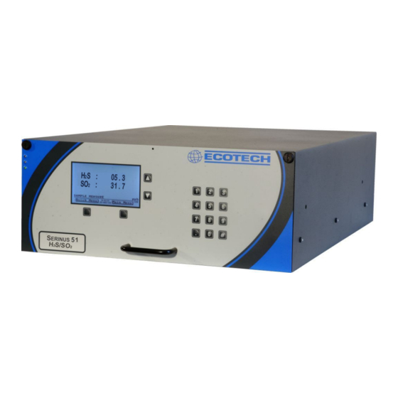
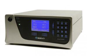
Газоанализаторы Serinus 50 (одноканальный), Serinus 51 (двухканальный), Serinus 55 (одноканальный) являются стационарными автоматическими приборами непрерывного действия, выполненные в едином корпусе (рис. 1 — 3).
На передней панели расположены дисплей и клавиатура для управления прибором, USB порт для переустановки программного обеспечения и копирования базы данных. Внутри корпуса установлены поглотительные фильтры, источник ультрафиолетового излучения (УФ-излучения), флуоресцентная измерительная ячейка, детектор, газовые линии, электронная схема и блок питания, а так же каталитический конвертор (Serinus 55 и Serinus 51), внешний насос (встроенный насос как опция для Serinus 55 и Serinus 51).
В основе принципа действия газоанализатора лежит флуоресцентный метод определения диоксида серы. Интенсивность флуоресценции, вызванной воздействием УФ-излучения пропорциональная содержанию диоксида серы в анализируемом газе, фиксируется оптической измерительной системой и преобразуется в электрический сигнал.
Проба газа, отбираемая с помощью внешнего или внутреннего насоса, проходит через поглотитель пыли и углеводородов и поступает в измерительную ячейку. В газоанализаторах Serinus 55 проба газа проходит дополнительно через поглотительный фильтр, селективно улавливающий SO2, но пропускающий H2S (скруббер), и поступает в каталитический конвертор, где происходит окисление H2S до SO2. После этого проба поступает в измерительную ячейку.
УФ-излучение от источника (цинковой разрядной лампы) проходит через полосовой оптический фильтр, пропускающий излучение в диапазоне от 200 до 240 нм, облучает измерительную ячейку с пробой газа, где взаимодействует с молекулами SO2, вызывая флуоресцентное излучение, которое через оптический фильтр поступает в фотоумножительный детектор и преобразуется в электрический сигнал. Сигнал детектора обрабатывается с помощью встроенного ПО, результат измерений отображается на дисплее.
В газоанализаторах Serinus 51 реализованы оба метод определения: как диоксида серы SO2, так и сероводорода H2S. Пользователь может выбрать режим определения двух компонентов или одного из них.
Результаты измерений могут быть представлены как в млн-1 (ppm), млрд.-1 (ppb), так и в пересчете в мг/м3 (мкг/м3), приведенных к температуре 0оС, 20оС, 25оС.
Газоанализаторы Serinus 50, Serinus 51, Serinus 55 имеют следующие цифровые разъемы (стандартная комплектация):
— RS232 — 2 (стандартный и многоточечный), USB — 1 на задней панели и 1 на передней,
— 25 контактный разъем вход/выход
— Беспроводной интерфейс — Bluetooth
— Ethernet (Опция)
Дополнительно газоанализатор может иметь следующие аналоговые каналы (опция):
— выходные: (0 — 20) мА, (2 — 20) мА, (4 — 20) мА;
— входные: (0 — 5) В постоянного тока (до трех каналов).
Программное обеспечение
Идентификационные данные программного обеспечения
Таблица 1
|
Наименование программного обеспечения |
Идентификационное наименование программного обеспечения |
Номер версии (идентификационный номер) программного обеспечения |
Цифровой идентификатор программного обеспечения (контрольная сумма исполняемого кода) |
Алгоритм вычисления цифрового идентификатора программного обеспечения |
|
Serinus Firmware |
2_14_000.S19 |
Не ниже 2.14.0000 |
— |
— |
Газоанализаторы Serinus 50, Serinus 51, Serinus 55 имеют уровень защиты «А» по МИ 3286-2010 (не требуется специальных средств защиты, исключающих возможность несанкционированной модификации, обновления (загрузки), удаления и иных преднамеренных изменений метрологически значимой встроенной части ПО СИ и измеренных данных).
Влияние программного обеспечения газоанализаторов учтено при нормировании метрологических характеристик.
Технические характеристики
Диапазон измерений объемной доли диоксида серы SO2, млн-1 Пределы допускаемой погрешности, %:
от 0 до 20
± 15 ± 15
от 0 до 2,0
± 10 ± 10
180
311
429x175x638
20,0
— приведенной, в диапазоне от 0 до 0,20 млн-1
— относительной, в диапазоне от 0,20 до 20 млн-1 Диапазон измерений объемной доли сероводорода H2S, млн-1 Пределы допускаемой погрешности, %:
— приведенной, в диапазоне от 0 до 0,010 млн-1
-1
— относительной, в диапазоне от 0,010 до 2,0 млн»
Время установления выходного сигнала (при достижении 90 % сигнала, Т0,9), с, не более
Потребляемая мощность, Вт, не более Габаритные размеры, мм, не более Масса, кг, не более
Условия эксплуатации: температура окружающего воздуха, °С относительная влажность воздуха, % атмосферное давление, кПа электрическое питание:
от 5 до 40 от 20 до 95 101,3 ± 10
от 198 до 264; 50 ± 3.
напряжение переменного тока, В частота переменного тока, Гц
Знак утверждения типа
наносится на газоанализатор способом наклейки и на титульный лист руководства по эксплуатации типографским способом.
Комплектность
Газоанализатор Serinus 50, Serinus 51, Serinus 55 (по заказу).
Насос встроенный или внешний (опция для Serinus 50 и Serinus 55). Руководство по эксплуатации.
Методика поверки.
осуществляется по документу МП 56054-13 «Инструкция. Газоанализаторы Serinus 50, Serinus 51, Serinus 55. Методика поверки», утвержденному ФГУП «ВНИИМС» 14.11.2013 г. и входящему в комплект поставки.
Основные средства поверки:
— генератор газовых смесей ГГС-03-03 по ШДЕК.418313.001 ТУ;
— ГСО №№ 9195-2008, 9172-2008;
— эталон сравнения — чистый газ с нормированным содержанием определяемых примесей Хд.2.706.142-ЭТ1 (синтетический воздух) по ГОСТ 8.578-2008.
Сведения о методах измерений
приведены в руководствах по эксплуатации на газоанализаторы Serinus 50, Serinus 51, Serinus 55.
Нормативные и технические документы, устанавливающие требования к газоанализаторам Serinus 50, Serinus 51, Serinus 55
ГОСТ 8.578-2008 Государственная система обеспечения единства измерений. Государственная поверочная схема для средств измерений содержания компонентов в газовых средах. ГОСТ 12.1.005-88 Система стандартов безопасности труда. Общие санитарно-гигиенические требования к воздуху рабочей зоны.
ГОСТ 17.2.4.02-81 Охрана природы. Атмосфера. Общие требования к методам определения загрязняющих веществ
Техническая документация фирмы-изготовителя «Ecotech Pty Ltd.», Австралия.
Рекомендации к применению
— осуществление деятельности в области охраны окружающей среды;
— выполнение работ по обеспечению безопасных условий и охраны труда.
|
Газоанализатор SO2/H2S Serinus 51 Анализатор Serinus 51 обеспечивает точное и надежное измерение диоксида серы и сероводорода в атмосферном водухе. Он сочетает в себе принцип флуоресценции и внутренний каталитический конвертор для поочередного измерения H2S и SO2 в диапазонах 0-2/0-20 ppm с нижним пределом обнаружения 0,3 ppb. Процесс анализа состоит из двух циклов:
ПРЕИМУЩЕСТВА
ПЕРЕДАЧА ДАННЫХ:
ВХОДЫ/ВЫХОДЫ: входной/выходной порт 25 контактов
ЗАПИСЬ ДАННЫХ: USB флеш-память, запись следующих данных:
ОПЦИИ:
|
ТЕХНИЧЕСКИЕ ХАРАКТЕРИСТИКИ
|

Назначение: для непрерывного автоматического определения содержания диоксида серы SO2 (Serinus 50), диоксида серы SO2 и сероводорода H2S (Serinus 51), сероводорода H2S (Serinus 55) в атмосферном воздухе, в воздухе рабочей зоны, промышленных выбросах и в технологических газовых смесях.
Поверка газоанализатора Serinus 50, Serinus 51, Serinus 55
Газоанализаторы Serinus 50 (одноканальный), Serinus 51 (двухканальный), Serinus 55 (одноканальный) являются стационарными автоматическими приборами непрерывного действия, выполненные в едином корпусе.
На передней панели расположены дисплей и клавиатура для управления прибором, USB порт для переустановки программного обеспечения и копирования базы данных. Внутри корпуса установлены поглотительные фильтры, источник ультрафиолетового излучения (УФ-излучения), флуоресцентная измерительная ячейка, детектор, газовые линии, электронная схема и блок питания, а так же каталитический конвертор (Serinus 55 и Serinus 51), внешний насос (встроенный насос как опция для Serinus 55 и Serinus 51).
В основе принципа действия газоанализатора лежит флуоресцентный метод определения диоксида серы. Интенсивность флуоресценции, вызванной воздействием УФ-излучения пропорциональная содержанию диоксида серы в анализируемом газе, фиксируется оптической измерительной системой и преобразуется в электрический сигнал.
Проба газа, отбираемая с помощью внешнего или внутреннего насоса, проходит через поглотитель пыли и углеводородов и поступает в измерительную ячейку. В газоанализаторах Serinus 55 проба газа проходит дополнительно через поглотительный фильтр, селективно улавливающий SO2, но пропускающий H2S (скруббер), и поступает в каталитический конвертор, где происходит окисление H2S до SO2. После этого проба поступает в измерительную ячейку.
УФ-излучение от источника (цинковой разрядной лампы) проходит через полосовой оптический фильтр, пропускающий излучение в диапазоне от 200 до 240 нм, облучает измерительную ячейку с пробой газа, где взаимодействует с молекулами SO2, вызывая флуоресцентное излучение, которое через оптический фильтр поступает в фотоумножительный детектор и преобразуется в электрический сигнал. Сигнал детектора обрабатывается с помощью встроенного ПО, результат измерений отображается на дисплее.
В газоанализаторах Serinus 51 реализованы оба метод определения: как диоксида серы SO2, так и сероводорода H2S. Пользователь может выбрать режим определения двух компонентов или одного из них.
Результаты измерений могут быть представлены как в млн-1 (ppm), млрд.-1 (ppb), так и в пересчете в мг/м3 (мкг/м3), приведенных к температуре 0оС, 20оС, 25оС.
Газоанализаторы Serinus 50, Serinus 51, Serinus 55 имеют следующие цифровые разъемы (стандартная комплектация):
- RS232 — 2 (стандартный и многоточечный), USB — 1 на задней панели и 1 на передней, 25 контактный разъем вход/выход
- Беспроводной интерфейс — Bluetooth
- Ethernet (Опция)
Дополнительно газоанализатор может иметь следующие аналоговые каналы (опция):
- выходные: (0 — 20) мА, (2 — 20) мА, (4 — 20) мА;
- входные: (0 — 5) В постоянного тока (до трех каналов).
Программное обеспечение
Идентификационные данные программного обеспечения
| Наименование
программного обеспечения |
Идентификационное наименование программного обеспечения | Номер версии (идентификационный номер) программного обеспечения | Цифровой идентификатор программного обеспечения (контрольная сумма исполняемого кода) | Алгоритм вычисления цифрового идентификатора программного обеспечения |
| Serinus Firmware | 2_14_000.S19 | Не ниже 2.14.0000 | — | — |
Газоанализаторы Serinus 50, Serinus 51, Serinus 55 имеют уровень защиты «А» по МИ 3286-2010 (не требуется специальных средств защиты, исключающих возможность несанкционированной модификации, обновления (загрузки), удаления и иных преднамеренных изменений метрологически значимой встроенной части ПО СИ и измеренных данных).
Влияние программного обеспечения газоанализаторов учтено при нормировании метрологических характеристик.
Поверка осуществляется по документу МП 56054-13 «Инструкция. Газоанализаторы Serinus 50, Serinus 51, Serinus 55. Методика поверки», утвержденному ФГУП «ВНИИМС» 14.11.2013 г. и входящему в комплект поставки.
Основные средства поверки:
- генератор газовых смесей ГГС-03-03 по ШДЕК.418313.001 ТУ;
- ГСО №№ 9195-2008, 9172-2008;
- эталон сравнения — чистый газ с нормированным содержанием определяемых примесей Хд.2.706.142-ЭТ1 (синтетический воздух) по ГОСТ 8.578-2008.
Сведения о методах измерений
- приведены в руководствах по эксплуатации на газоанализаторы Serinus 50, Serinus 51, Serinus 55.
Нормативные и технические документы, устанавливающие требования к газоанализаторам Serinus 50, Serinus 51, Serinus 55
- ГОСТ 8.578-2008 Государственная система обеспечения единства измерений. Государственная поверочная схема для средств измерений содержания компонентов в газовых средах. ГОСТ 12.1.005-88 Система стандартов безопасности труда. Общие санитарно-гигиенические требования к воздуху рабочей зоны.
- ГОСТ 17.2.4.02-81 Охрана природы. Атмосфера. Общие требования к методам определения загрязняющих веществ
- Техническая документация фирмы-изготовителя «Ecotech Pty Ltd.», Австралия.