 Contents:
1. General;
2. Specifications;
3. Consumable parts;
4. External views and internal structures;
5. Unpacking and installation;
6. Adjustments;
7. Simulations;
8. User Programs;
9. Trouble code list;
Trouble code list;
Details of trouble codes;
10. Maintenance;
11. Disassembly and assembly;
12. Flash ROM version up procedure;
Preparation;
Download procedure;
Installation procedure;
13. Electrical section.
Download Sharp AR-5316. Service Manual
Все материалы на сайте представлены исключительно для ознакомления. Все торговые марки и права на публикуемые материалы принадлежат их владельцам.
All materials on the site are presented solely for information. All trademarks and copyrights in the published materials belong to their respective owners.
-
Contents
-
Table of Contents
-
Bookmarks
Quick Links
AR-5316
(With optional AR-SP6 installed)
[ 1 ] GENERAL . . . . . . . . . . . . . . . . . . . . . . . . . . . . . . . . . . . . . . . . . . . . . . . . .1-1
[ 2 ] SPECIFICATIONS . . . . . . . . . . . . . . . . . . . . . . . . . . . . . . . . . . . . . . . . . . .2-1
[ 3 ] CONSUMABLE PARTS. . . . . . . . . . . . . . . . . . . . . . . . . . . . . . . . . . . . . . .2-1
[ 4 ] EXTERNAL VIEWS AND INTERNAL STRUCTURES . . . . . . . . . . . . . . .4-1
[ 5 ] UNPACKING AND INSTALLATION . . . . . . . . . . . . . . . . . . . . . . . . . . . . . .5-1
[ 6 ] ADJUSTMENTS . . . . . . . . . . . . . . . . . . . . . . . . . . . . . . . . . . . . . . . . . . . .6-1
[ 7 ] SIMULATIONS . . . . . . . . . . . . . . . . . . . . . . . . . . . . . . . . . . . . . . . . . . . . .7-1
[ 8 ] USER PROGRAMS . . . . . . . . . . . . . . . . . . . . . . . . . . . . . . . . . . . . . . . . .8-1
[ 9 ] TROUBLE CODE LIST . . . . . . . . . . . . . . . . . . . . . . . . . . . . . . . . . . . . . . .9-1
[10] MAINTENANCE . . . . . . . . . . . . . . . . . . . . . . . . . . . . . . . . . . . . . . . . . . .10-1
[11] DISASSEMBLY AND ASSEMBLY . . . . . . . . . . . . . . . . . . . . . . . . . . . . . .11-1
[12] FLASH ROM VERSION UP PROCEDURE . . . . . . . . . . . . . . . . . . . . . .12-1
[13] ELECTRICAL SECTION . . . . . . . . . . . . . . . . . . . . . . . . . . . . . . . . . . . . .13-1
Parts marked with «
» are important for maintaining the safety of the set.
Be sure to replace these parts with specified ones for maintaining the safety and performance of the set.
CONTENTS
SHARP CORPORATION
CODE : 00ZAR5316/A1E
DIGITAL COPIER
MODEL
(For North America)
This document has been published to be used for
after sales service only.
The contents are subject to change without notice.
AR-5316
Summary of Contents for Sharp AR-5316
Новости
Самые популярные статьи
-
Принтеры и МФУ -
-
Epson с СНПЧ и ПЗК -
Прошитый Samsung -
Принтер и МФУ HP -
Oki принтеры и мфу -
Ручной принтер -
Прошитый МФУ, принтер Pantum
-
-
СНПЧ -
-
СНПЧ Epson -
СНПЧ Canon -
СНПЧ Hp -
СНПЧ Brother -
СНПЧ Конструктор ( комплектующие )
-
-
Принтеры в разборе -
-
Epson струйные и лазерные принтеры и мфу -
HP струйные и лазерные принтеры и мфу -
Canon струйные и лазерные принтеры и мфу -
Samsung лазерные принтеры и мфу -
Brother струйные и лазерные принтеры и мфу -
OKI струйные и лазерные принтеры и МФУ -
Panasonic лазерные принтеры и мфу -
Xerox лазерные принтеры и МФУ -
Sharp лазерные принтеры и МФУ -
Ricoh лазерные принтеры и МФУ -
Kyocera лазерные принтеры и МФУ
-
-
ПЗК -
-
ПЗК Epson -
ПЗК HP -
ПЗК Canon -
ПЗК Brother
-
-
Чернила -
-
Чернила Epson -
Чернила Canon -
Чернила HP -
Чернила Brother -
Чернила Epson, Canon, HP в канистре
-
-
Фотобумага -
-
Фотобумага глянцевая -
Фотобумага матовая -
Фотобумага фактурная. Дизайнерская -
Рулонная фотобумага -
Фотобумага мелованная (2-х сторонний глянец для струйной печати) -
Оригинальная фотобумага HP, Canon, Epson
-
-
Термобумага для терминалов и банкоматов -
Тонер -
-
Тонер HP -
Тонер Samsung -
Тонер Canon -
Тонер Epson -
Тонер Xerox -
Тонер Brother -
Тонер Panasonic -
Тонер Kyocera -
Тонер OKI -
Тонер Ricoh -
Тонер Toshiba -
Тонер Konica -
Тонер Sharp -
Тонер Handan -
Тонер Lexmark
-
-
Лазерные картриджи -
-
Картридж Epson -
Картридж Canon -
Картридж HP -
Картридж Samsung -
Картридж Xerox -
Картридж Brother -
Картридж Panasonic -
Картридж Kyocera -
Картридж OKI -
Картридж Toshiba, Sharp, Lexmark, Ricoh
-
-
ЗИП для картриджа -
-
ЗИП картриджа Canon -
ЗИП картриджа HP -
ЗИП картриджа Samsung -
ЗИП картриджа Xerox -
ЗИП картриджа Brother -
ЗИП картриджа Panasonic -
ЗИП картриджа Lexmark -
ЗИП картриджа Ricoh, Kyocera, Sharp -
Пакеты для картриджей
-
-
Комплектующие (ЗИП) для принтера -
-
ЗИП Epson -
-
Print Head ( Печатающая головка ) -
Pump Assy ( Узел подачи чернил в сборе ) -
Board Assy ( Электронная плата ) -
DAMPER ( Демпер ) -
Cable Assy ( Шлейф в сборе ) -
Belt, Scale ( ремень каретки, лента позиционирования ) -
Motor Assy ( двигатель ) -
Paper feed unit ( узел подачи бумаги ) -
Gear ( Шестерня ) -
Scaner unit ( блок сканера ) -
Power Assy ( блок питания ) -
Разное Epson
-
-
ЗИП Canon -
-
Печатающая головка Canon -
Электронная плата Canon -
Узел термозакрепления Canon -
Узел подачи бумаги Canon -
Ремни, ленты позиционирования, диски энкодера Canon -
Шлейфы Canon -
Узел подачи чернил Canon -
Шестеренки Canon -
Блоки питания Canon -
Электродвигатели и соленоиды Canon -
Датчики Canon -
Разное Canon
-
-
ЗИП HP -
-
Печатающая головка HP -
Электронная плата HP -
Узел термозакрепления HP -
Узел подачи бумаги HP -
Ремни, ленты позиционирования, диски энкодера HP -
Шлейфы HP -
Узел подачи чернил HP -
Модули памяти HP -
Шестеренки HP -
Подшипники (бушинги) HP -
Блоки питания HP -
Электродвигатели и соленоиды HP -
Узел сканирования HP -
Датчики HP -
Разное HP
-
-
ЗИП Samsung -
-
Электронная плата Samsung -
Узел термозакрепления Samsung -
Узел подачи бумаги Samsung -
Шлейфы Samsung -
Шестеренки Samsung -
Подшипники (бушинги) Samsung -
Блоки питания Samsung -
Электродвигатели и соленоиды Samsung -
Узел сканирования Samsung -
Блок лазера Samsung -
Датчики Samsung -
Разное Samsung. Товары, не вошедшие в предыдущие категории
-
-
ЗИП Xerox -
-
Печатающая головка Xerox -
Электронная плата Xerox -
Узел термозакрепления Xerox -
Узел подачи бумаги Xerox -
Ремни, ленты позиционирования, диски энкодера Xerox -
Шлейфы Xerox -
Узел подачи чернил Xerox -
Шестеренки Xerox -
Электродвигатели и соленоиды Xerox -
Блоки питания Xerox -
Узел сканирования Xerox -
Датчики Xerox -
Блок лазера Xerox -
Разное Xerox
-
-
ЗИП Brother -
-
Печатающая головка Brother -
Электронная плата Brother -
Узел термозакрепления Brother -
Узел подачи бумаги Brother -
Ремни, ленты позиционирования, диски энкодера Brother -
Шлейфы Brother -
Узел подачи чернил Brother -
Шестеренки Brother -
Блоки питания Brother -
Электродвигатели и соленоиды Brother -
Датчики Brother -
Узел сканирования Brother -
Блок лазера Brother -
Разное Brother
-
-
ЗИП Kyocera -
-
Электронная плата Kyocera -
Узел термозакрепления Kyocera -
Узел подачи бумаги Kyocera -
Шлейфы Kyocera -
Шестеренки Kyocera -
Подшипники (бушинги) Kyocera -
Блоки питания Kyocera -
Электродвигатели и соленоиды Kyocera -
Узел сканирования Kyocera -
Блок лазера Kyocera -
Датчики Kyocera -
Разное Kyocera. Товары, не вошедшие в предыдущие категории
-
-
ЗИП Panasonic, OKI, Ricoh, Pantum -
-
Печатающая головка Panasonic, Oki, Ricoh, Pantum -
Электронная плата Panasonic, Oki, Ricoh, Pantum -
Узел термозакрепления Panasonic, Oki, Ricoh, Pantum -
Узел подачи бумаги Panasonic, Oki, Ricoh, Pantum -
Ремни, ленты позиционирования, диски энкодера Panasonic, Oki, Ricoh, Pantum -
Шлейфы Panasonic, Oki, Ricoh, Pantum -
Узел подачи чернил Panasonic, Oki, Ricoh, Pantum -
Шестеренки Panasonic, Oki, Ricoh, Pantum -
Блоки питания Panasonic, Oki, Ricoh, Pantum -
Электродвигатели и соленоиды Panasonic, Oki, Ricoh, Pantum -
Датчики Panasonic, Oki, Ricoh, Pantum -
Узел сканирования Panasonic, Oki, Ricoh, Pantum -
Блок лазера Panasonic, Oki, Ricoh, Pantum -
Разное Panasonic, Oki, Ricoh, Pantum
-
-
ЗИП Lexmark, Toshiba, Sharp -
-
Печатающая головка Lexmark, Toshiba, Sharp -
Электронная плата Lexmark, Toshiba, Sharp -
Узел термозакрепления Lexmark, Toshiba, Sharp -
Узел подачи бумаги Lexmark, Toshiba, Sharp -
Ремни, ленты позиционирования, диски энкодера Lexmark, Toshiba, Sharp -
Шлейфы Lexmark, Toshiba, Sharp -
Узел подачи чернил Lexmark, Toshiba, Sharp -
Шестеренки Lexmark, Toshiba, Sharp -
Блоки питания Lexmark, Toshiba, Sharp -
Электродвигатели и соленоиды Lexmark, Toshiba, Sharp -
Узел сканирования Lexmark, Toshiba, Sharp -
Блок лазера Lexmark, Toshiba, Sharp -
Датчики Lexmark, Toshiba, Sharp -
Разное Lexmark, Toshiba, Sharp
-
-
ЗИП Термопринтера -
Стекла для МФУ и сканера
-
-
Струйные картриджи -
-
Картриджи Epson -
Картриджи Canon -
Картриджи HP -
Картриджи Brother, Lexmark, Sharp
-
-
Чипы -
-
Чипы Epson -
Чипы Canon -
Чипы HP -
Чипы Samsung -
Чипы Xerox -
Чипы OKI -
Чипы Ricoh -
Чипы Pantum -
Чипы Kyocera -
Чипы Lexmark
-
-
Решение для принтера -
-
Прошивка Epson -
Генераторы, Прошивки Samsung -
Генераторы, Прошивки Xerox -
Прошитая оригиналом память -
Прошивка принтера Pantum -
Прошивки и Сервисные программы Canon
-
-
Химия для техники -
-
Промывочная жидкость -
Смазки и масла для техники -
Восстанавливающие, очищающие средства
-
-
Программаторы -
Радиодетали -
-
Транзисторы -
Микросхемы памяти FLASH -
Микросхемы памяти EEPROM -
Микроконтроллеры -
Конденсаторы -
Блок питания
-
-
Материалы для наружной рекламы -
Сублимация -
3D печать ABS PLA -
Планшетный принтер, текстильная печать -
Разработка сайтов и программного обеспечения -
Для ноутбука -
-
Зарядные устройства -
Аккумуляторы
-
-
Запчасти для телевизоров и мониторов -
-
Электронные платы для телевизоров -
Матрицы для телевизора -
Блоки питания для телевизоров -
Тюнеры для телевизора -
Светодиодная подсветка -
Шлейфы и кабели для телевизоров и мониторов -
Разное для телевизоров и мониторов
-
-
Запчасти для асиков (asic miner)
Вход
Самое покупаемое

-
Драйверы
3
-
Руководства по ремонту
1

Sharp AR-5316 сервис-мануал
(19 страниц)
- Языки:Английский
-
Тип:
PDF -
Размер:
4.16 MB
Просмотр
Sharp AR-5316 (Принтеры) сервис мануалы в PDF-формате помогут найти неполадки и ошибки, а также осуществить ремонт Sharp AR-5316 и восстановить работу устройства.
 Loading…
![]()
CODE : 00ZAR5316/A1E
DIGITAL COPIER
MODEL AR-5316
(For North America)
(With optional AR-SP6 installed)
CONTENTS
[ 1 ] GENERAL . . . . . . . . . . . . . . . . . . . . . . . . . . . . . . . . . . . . . . . . . . . . . . . . .1-1 [ 2 ] SPECIFICATIONS. . . . . . . . . . . . . . . . . . . . . . . . . . . . . . . . . . . . . . . . . . .2-1 [ 3 ] CONSUMABLE PARTS. . . . . . . . . . . . . . . . . . . . . . . . . . . . . . . . . . . . . . .2-1 [ 4 ] EXTERNAL VIEWS AND INTERNAL STRUCTURES . . . . . . . . . . . . . . .4-1 [ 5 ] UNPACKING AND INSTALLATION . . . . . . . . . . . . . . . . . . . . . . . . . . . . . .5-1 [ 6 ] ADJUSTMENTS . . . . . . . . . . . . . . . . . . . . . . . . . . . . . . . . . . . . . . . . . . . .6-1 [ 7 ] SIMULATIONS . . . . . . . . . . . . . . . . . . . . . . . . . . . . . . . . . . . . . . . . . . . . .7-1 [ 8 ] USER PROGRAMS . . . . . . . . . . . . . . . . . . . . . . . . . . . . . . . . . . . . . . . . .8-1 [ 9 ] TROUBLE CODE LIST . . . . . . . . . . . . . . . . . . . . . . . . . . . . . . . . . . . . . . .9-1 [10] MAINTENANCE . . . . . . . . . . . . . . . . . . . . . . . . . . . . . . . . . . . . . . . . . . .10-1 [11] DISASSEMBLY AND ASSEMBLY . . . . . . . . . . . . . . . . . . . . . . . . . . . . . .11-1 [12] FLASH ROM VERSION UP PROCEDURE . . . . . . . . . . . . . . . . . . . . . .12-1 [13] ELECTRICAL SECTION . . . . . . . . . . . . . . . . . . . . . . . . . . . . . . . . . . . . .13-1
Parts marked with “ “ are important for maintaining the safety of the set.
Be sure to replace these parts with specified ones for maintaining the safety and performance of the set.
This document has been published to be used for SHARP CORPORATION after sales service only.
The contents are subject to change without notice.
CONTENTS
[1] GENERAL
1. Note for servicing . . . . . . . . . . . . . . . . . . . . . . . . . . . . . 1-1
[2] SPECIFICATIONS
1. Copy mode . . . . . . . . . . . . . . . . . . . . . . . . . . . . . . . . . . 2-1
[3] CONSUMABLE PARTS
1. Supply system table . . . . . . . . . . . . . . . . . . . . . . . . . . . 2-1
[4] EXTERNAL VIEWS AND INTERNAL STRUCTURES
1. Appearance . . . . . . . . . . . . . . . . . . . . . . . . . . . . . . . . . 4-1 2. Internal . . . . . . . . . . . . . . . . . . . . . . . . . . . . . . . . . . . . . 4-1 3. Operation Section. . . . . . . . . . . . . . . . . . . . . . . . . . . . . 4-2 4. Motor, solenoid, clutch . . . . . . . . . . . . . . . . . . . . . . . . . 4-3
[5] UNPACKING AND INSTALLATION
5. Changing the copy paper size in the tray . . . . . . . . . . . 5-1
[6] ADJUSTMENTS
1. Adjustment item list . . . . . . . . . . . . . . . . . . . . . . . . . . . 6-1 2. Copier adjustment . . . . . . . . . . . . . . . . . . . . . . . . . . . . 6-1
[7] SIMULATIONS
1. Entering the simulation mode. . . . . . . . . . . . . . . . . . . . 7-1 2. Canceling the simulation mode . . . . . . . . . . . . . . . . . . 7-1 3. List of simulations. . . . . . . . . . . . . . . . . . . . . . . . . . . . . 7-1 4. Contents of simulations . . . . . . . . . . . . . . . . . . . . . . . . 7-2
[8] USER PROGRAMS
1. List of user programs . . . . . . . . . . . . . . . . . . . . . . . . . . 8-1
[9] TROUBLE CODE LIST
1. Trouble code list . . . . . . . . . . . . . . . . . . . . . . . . . . . . . . 9-1 2. Details of trouble codes . . . . . . . . . . . . . . . . . . . . . . . . 9-1
[10] MAINTENANCE
1. Maintenance table. . . . . . . . . . . . . . . . . . . . . . . . . . . . . 10-1 2. Maintenance display system . . . . . . . . . . . . . . . . . . . . . 10-1 3. Note for replacement of consumable parts . . . . . . . . . . 10-1
[11] DISASSEMBLY AND ASSEMBLY
1. High voltage section . . . . . . . . . . . . . . . . . . . . . . . . . . . 11-1 2. Optical section . . . . . . . . . . . . . . . . . . . . . . . . . . . . . . . 11-2 3. Fusing section . . . . . . . . . . . . . . . . . . . . . . . . . . . . . . . . 11-4 4. Paper exit section . . . . . . . . . . . . . . . . . . . . . . . . . . . . . 11-6 5. MCU . . . . . . . . . . . . . . . . . . . . . . . . . . . . . . . . . . . . . . . 11-8 6. Optical frame unit . . . . . . . . . . . . . . . . . . . . . . . . . . . . . 11-8 7. LSU . . . . . . . . . . . . . . . . . . . . . . . . . . . . . . . . . . . . . . . . 11-9 8. Tray paper feed section / Paper transport section . . . . . 11-9 9. Manual multi paper feed section . . . . . . . . . . . . . . . . . . 11-11 10. Power section . . . . . . . . . . . . . . . . . . . . . . . . . . . . . . . 11-13 11. Developing section . . . . . . . . . . . . . . . . . . . . . . . . . . . 11-14 12. Process section. . . . . . . . . . . . . . . . . . . . . . . . . . . . . . 11-15 13. Others . . . . . . . . . . . . . . . . . . . . . . . . . . . . . . . . . . . . . 11-15
[12] FLASH ROM VERSION UP PROCEDURE
1. Preparation . . . . . . . . . . . . . . . . . . . . . . . . . . . . . . . . . . 12-1 2. Download procedure . . . . . . . . . . . . . . . . . . . . . . . . . . . . 12-1 3. Installation procedure . . . . . . . . . . . . . . . . . . . . . . . . . . . 12-2
[13] ELECTRICAL SECTION
1. Block diagram . . . . . . . . . . . . . . . . . . . . . . . . . . . . . . . . 13-1 3. Actual wiring diagram . . . . . . . . . . . . . . . . . . . . . . . . . . 13-2

[1] GENERAL
1. Note for servicing
Pictogram
The label (
 ) in the fusing area of the machine indicates the following:
 : Caution, risk of danger
  : Caution, hot surface
A. Warning for servicing
•The fusing area is hot. Exercise care in this area when removing misfed paper.
•Do not look directly at the light source. Doing so may damage your eyes.
B. Cautions for servicing
•Do not switch the machine rapidly on and off. After turning the machine off, wait 10 to 15 seconds before turning it back on.
•Machine power must be turned off before installing any supplies. •Place the machine on a firm, level surface.
•Do not install the machine in a humid or dusty location.
•When the machine is not used for a long time, for example, during prolonged holidays, turn the power switch off and remove the power cord from the outlet.
•When moving the machine, be sure to turn the power switch off and remove the power cord from the outlet.
•Do not cover the machine with a dust cover, cloth or plastic film while the power is on. Doing so may prevent heat dissipation, damaging the machine.
•Use of controls or adjustments or performance of procedures other than those specified herein may result in hazardous laser radiation exposure.
•The socket-outlet shall be installed near the machine and should be easily accessible.
C. Note for installation place
Improper installation may damage the machine. Please note the following during initial installation and whenever the machine is moved.
Caution : If the machine is moved from a cool place to a warm place, condensation may form inside the machine. Operation in this condition will cause poor copy quality and malfunctions. Leave the machine at room temperature for at least 2 hours before use.
Do not install your machine in areas that are:
•damp, humid, or very dusty
•poorly ventilated
•exposed to direct sunlight
•subject to extreme temperature or humidity changes, e.g., near an air conditioner or heater.
The machine should be installed near an accessible power outlet for easy connection and disconnection.
Be sure to connect the power cord only to a power outlet that meets the specified voltage and current requirements. Also make certain the outlet is properly grounded.
Note : Connect the machine to a power outlet which is not used for other electric appliances. If a lighting fixture is connected to the same outlet, the light may flicker.
Be sure to allow the required space around the machine for servicing and proper ventilation.
8″ (20 cm)
AR-5316 GENERAL 1-1
[2] SPECIFICATIONS
The table below shows the specifications of this model and the contents of changes from the AR-M160/M205 and AR-5316.
|
Item |
AR-M160 |
AR-5316 |
|||||
|
Paper feed system |
1cassette + |
One automatic feeding paper tray(250sheets) + |
|||||
|
Multi manual paper feed |
bypass tray(100sheets) |
||||||
|
Weight |
Approx.31.3Kg |
Approx.31.3Kg |
|||||
|
(Not including TD cartridge) |
|||||||
|
Interface |
USB1.1/USB2.0 |
IEEE1284parallel connector/USB1.1 |
|||||
|
IEEE1284 |
|||||||
|
Option |
|||||||
|
Machine |
Model |
AR-M160 |
AR-5316 |
Remark |
|||
|
250 sheets paper feed unit |
AR-D24 / D25 |
O |
— |
||||
|
SPF |
AR-SP6 |
O |
O |
||||
|
Original cover |
AR-VR5 |
Standard |
Standard |
||||
O : The option can be installed.
— : The option cannot be installed.
[3] CONSUMABLE PARTS
1. Supply system table
|
NO |
Name |
Content |
Life |
Product name |
Remark |
|
|
1 |
TD cartridge(Black) |
Toner developer cartridge |
x1 |
9K |
AR-016TD |
*Life setting by LT 5% document |
|
(Toner: Net Weight 300g) |
||||||
|
(Developer: Net Weight 400g) |
||||||
|
IC chip |
x1 |
|||||
|
Polyethylene bag |
x1 |
|||||
|
2 |
Drum cartridge |
Drum cartridge |
x1 |
30K |
AR-016DR |
|
Packed items:DR cartridge(30K)/TD cartridge(4.5K)
Note 1: The individual carton is printed with English, German, French, and Spanish as well as the green mark.
AR-5316 SPECIFICATIONS 2-1

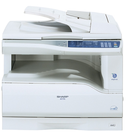
[4] EXTERNAL VIEWS AND INTERNAL STRUCTURES
1. Appearance
1
2 
 7 6 2
7 6 2 
 10
10
 11
11
15
|
9 |
12 |
13 |
14 |
|||||||
|
1 |
Glass cleaner |
2 |
Document feeder cover (when the SPF |
3 |
Document glass |
|||||
|
is installed) /document cover |
||||||||||
|
4 |
Handles |
5 |
Power switch |
6 |
Operation panel |
|||||
|
7 |
Paper output tray |
8 |
Front cover |
9 |
Paper trays |
|||||
|
10 |
Side cover |
11 |
Side cover handle |
12 |
Bypass tray guides |
|||||
|
13 |
Bypass tray |
14 |
Bypass tray extension |
15 |
Charger cleaner |
|||||
|
16 |
USB 1.1 connector |
17 |
Parallel connector |
|||||||
|
2. Internal |
||||||||||
|
25 |
24 |
18 |
19 |
20 |
|
29 |
||||||
|
28 |
26 |
27 |
30 |
|||
|
18 |
Document feeder tray |
19 |
Original guides |
20 |
Feeding roller cover |
|
|
(when the SPF is installed) |
(when the SPF is installed) |
(when the SPF is installed) |
||||
|
21 |
Right side cover |
22 |
Exit area |
23 |
TD cartridge |
|
|
(when the SPF is installed) |
(when the SPF is installed) |
|||||
|
24 |
TD cartridge strap |
25 |
TD cartridge lock release lever |
26 |
Roller rotating knob |
|
|
27 |
Fusing unit release levers |
28 |
Drum cartridge |
29 |
Drum cartridge handle |
|
|
30 |
Fusing unit paper guide |
AR-5316 EXTERNAL VIEWS AND INTERNAL STRUCTURES 4-1

3. Operation Section
1 2 3
XY-
 ZOOM
ZOOM
ON LINE
DUAL
 PAGE
PAGE
COPY
|
1 |
ON LINE key/indicator |
2 |
DUAL PAGE COPY key/indicator |
3 |
XY-ZOOM key/indicator |
||||||||
|
4 |
SPF indicator |
5 |
Paper feed location / misfeed location |
6 |
ORIGINAL SIZE ENTER key / |
||||||||
|
(when the SPF is installed) |
indicators |
ORIGINAL SIZE indicators |
|||||||||||
|
7 |
PAPER SIZE indicators |
8 |
PRESET RATIO selector keys / |
||||||||||
|
indicators |
|||||||||||||
|
9 |
10 |
11 |
12 |
13 |
14 |
15 |
16 |
17 |
|||||
|
AUDIT CLEAR |
POWER SAVE |
ZOOM |
25 |
400% |
INTERRUPT |
||||||||
|
AUTO |
ORIGINAL PAPER |
200% |
CLEAR |
||||||||||
|
SIZE |
SIZE |
||||||||||||
|
TEXT |
141 |
||||||||||||
|
11X17 |
|||||||||||||
|
PHOTO |
8½X14 |
129 |
|||||||||||
|
8½X11 |
121 |
CLEAR ALL |
|||||||||||
|
100% |
|||||||||||||
|
8½X5½ |
|||||||||||||
|
95 |
|||||||||||||
|
8½X11 |
|||||||||||||
|
77 |
|||||||||||||
|
1 |
3 |
5 |
EXTRA |
64 |
|||||||||
|
50% |
START |
||||||||||||
|
ORIGINALSIZE |
TRAY |
AUTO |
|||||||||||
|
PRESET RATIO |
|||||||||||||
|
ENTER |
SELECT |
IMAGE |
|||||||||||
|
18 |
6 |
7 |
5 |
8 |
|||||||||||||||||
|
19 |
4 |
20 |
21 |
22 |
23 |
24 |
25 |
26 |
|||||||||||||
|
Not used |
for this machine. |
||||||||||||||||||||
|
9 |
AUTO/TEXT/PHOTO key / indicators |
10 |
AUDIT CLEAR key |
11 |
Alarm indicators |
||||||||||||||||
|
12 |
POWER SAVE indicator |
13 |
Display |
14 |
Copy ratio display key |
||||||||||||||||
|
15 |
ZOOM indicator |
16 |
Zoom keys |
17 |
INTERRUPT key / indicator |
||||||||||||||||
|
18 |
Light and Dark keys / indicators |
19 |
PAPER SIZE ENTER key |
20 |
TRAY SELECT key |
||||||||||||||||
|
21 |
AUTO IMAGE key / indicator |
22 |
Numeric keys |
23 |
# key |
||||||||||||||||
|
24 |
START key / indicator |
25 |
CLEAR ALL key |
26 |
CLEAR key |
AR-5316 EXTERNAL VIEWS AND INTERNAL STRUCTURES 4-2

[5]UNPACKING AND INSTALLATION
5. Changing a tray’s paper size setting
Follow these steps to change a tray’s paper size setting.
Note:
•The paper size setting cannot be changed when the machine has stopped temporarily due to running out of paper or a misfeed, or during interrupt copying.
•During printing (even in copy mode), the paper size setting cannot be changed.
•Do not load paper that is a different size than the paper size setting. Copying will not be possible.
1)Hold down the [PAPER SIZE ENTER] key for more than 5 seconds to set the selected paper size.
The currently selected paper feed location indicator will blink and the corresponding paper size (which is currently set) indicator will light steadily.
All other indicators will go out.
INAL PAPER SIZE 11X17 
8½X14  8½X11
8½X11
 8½X5½
8½X5½  8½X11
8½X11 EXTRA
EXTRA
3)Squeeze the lock lever of the front guide and slide the front guide to match the width of the paper, and move the left guide to the appropriate slot as marked on the tray.
Left guide
Front guide
•The front guide is a slide-type guide. Grasp the locking knob on the guide and slide the guide to the indicator line of the paper to be loaded. •The left guide is an insert-type guide. Remove it and then insert it at the indicator line of the paper to be loaded.
•When using 11″ x 17″ sized paper store the left guide in the slot at the left front of the paper tray.
2)Use the [ORIGINAL SIZE ENTER] key to select the paper size. The indicator of the selected paper size lights up.
GINAL PAPER
SIZE
|
ORIGINAL SIZE |
11X17 |
|
8½X14 |
ENTER 8½X11
 8½X5½
8½X5½  8½X11
8½X11  EXTRA
EXTRA 
4)Press the [START] key and then the [PAPER SIZE ENTER] key.
To change the paper size setting of another tray, repeat steps 2) to 4) after pressing the [START] key.
START
Note:Affix the paper size label for the paper size selected in step 2) to the label position on the right end of the tray.
Important points when using the printer mode
•Make sure that the tray’s paper size setting is the same as the tray’s paper size setting in the printer driver. For example, if the tray’s paper size setting is 8-1/2”x11R, set «Setting Paper Size» to «Letter R». For more information, see «CONFIGURING THE PRINTER DRIVER» in the «Software Setup Guide».
AR-5316 UNPACKING AND INSTALLATION 5-1

[6]ADJUSTMENTS
1.Adjustment item list
|
Section |
Adjustment item |
Adjustment procedure/SIM No. |
||
|
A |
Process |
(1) |
Developing doctor gap adjustment |
Developing doctor gap adjustment |
|
section |
||||
|
(2) |
MG roller main pole position adjustment |
MG roller main pole position adjustment |
||
|
(3) |
Developing bias voltage check |
|||
|
(4) |
Main charger voltage check |
|||
|
B |
Mechanism |
(1) |
Image position adjustment |
SIM-50 |
|
section |
||||
|
(2) |
Main scanning direction (FR direction) distortion balance |
No. 2/3 mirror base unit installing position adjustment |
||
|
adjustment |
||||
|
Copy lamp unit installing position adjustment |
||||
|
(3) |
Main scanning direction (FR direction) distortion adjustment |
Rail height adjustment |
||
|
(4) |
Sub scanning direction (scanning direction) distortion |
Winding pulley position adjustment |
||
|
adjustment |
||||
|
(5) |
Main scanning direction (FR direction) magnification ratio |
SIM 48-1 |
||
|
adjustment |
||||
|
(6) |
Sub scanning direction (scanning direction) magnification ratio |
OC mode in copying (SIM 48-1) |
||
|
adjustment |
||||
|
SPF mode in copying (SIM 48-5) |
||||
|
(7) |
Off center adjustment |
OC mode (SIM 50-12) |
||
|
SPF mode (SIM 50-12) |
||||
|
(8) |
SPF white correction pixel position adjustment |
SIM63-7 |
||
|
(required in an SPF model when replacing the lens unit) |
||||
|
C |
Image density |
(1) |
Copy mode |
SIM 46-1 |
|
adjustment |
||||
2.Copier adjustment
A.Process section
(1) Developing doctor gap adjustment
1)Loosen the developing doctor fixing screw A.
2)Insert a thickness gauge of 1.5mm to the three positions at 20mm and 130mm from the both ends of the developing doctor as shown.
3)Push the developing doctor in the arrow direction, and tighten the developing doctor fixing screw. (Perform the same procedure for the front and the rear frames.)
4)Check the clearance of the developing doctor. If it is within the specified range, then fix the doctor fixing screw with screw lock.
*When inserting a thickness gauge, be careful not to scratch the developing doctor and the MG roller.
<Adjustment specification>
Developing doctor gap
Both ends (20mm from the both ends) : 1.5 +0.1— 0.15 mm
C (Center) (150mm from the both ends) :1.55 +0.15— 0.2 mm
(2) MG roller main pole position adjustment
1)Remove and separate the waste toner box and put the developing unit on a flat surface.
2)Tie a string to a needle or a pin.
3)Hold the string and bring the needle close to the MG roller horizontally. (Do not use paper clip, which is too heavy to make a correct adjustment.) (Put the developing unit horizontally for this adjustment.)
4)Do not bring the needle into contact with the MG roller, but bring it to a position 2 or 3mm apart from the MG roller. Mark the point on the MG roller which is on the extension line from the needle tip.
5)Measure the distance from the marking position to the top of the doctor plate of the developing unit to insure that it is 18mm.
If the distance is not within the specified range, loosen the fixing screw A of the main pole adjustment plate, and move the adjustment plate in the arrow direction to adjust.
AR-5316 ADJUSTMENT 6-1

(3)Developing bias voltage check
Note:Use a digital multi-meter with an internal resistance of 10MΩ or more.
1)Set the digital multi-meter range to DC700V.
2)Put the test rod of the digital multi-meter on the developing bias voltage output check pin.
3)Turn on the power, execute SIM25-1.
<Specification>
|
Mode |
Specification |
|
Developing bias voltage |
DC — 400±8V |
(4) Grid bias voltage check
Note:Use a digital multi-meter with an internal resistance of 10MΩ or more.
1)Set the digital multi-meter range to DC700V.
2)Put the test rod of the digital multi-meter on the grid bias voltage output check pin.
3)Turn on the power.
(The voltage is outputted in the grid bias High output mode during warming up, and in the grid bias Low output mode when warming up is completed.)
<Specification>
|
Mode |
Specification |
|
Grid bias LOW |
DC — 400±8V |
|
Grid bias HIGH |
DC — 525±10V |
B.Mechanism section
Note: If a jam error or paper empty occurs during copying in the adjustment by the simulation, the image data are not saved, and therefore recopying is required.
(1)Image position adjustment
a.OC image lead edge position adjustment (SIM 50-1)
Note:In advance to this adjustment, the sub scanning magnification ratio adjustment must be performed.
1) Set a scale on the OC table as shown below.
2)Make a copy.
3)Check the copy output. If necessary, perform the following adjustment procedures.
4)Execute SIM 50-1.
5)Set the OC lead edge position set value (Exposure display <<PHOTO>> ON) to [1]
The OC image scanning start position is shifted inside the document edge.
6)Set the main cassette lead edge void adjustment value (Exposure display <<TEXT>> ON) * to [1]
The lead edge void becomes the minimum.
7)Set the main cassette print start position value (Exposure display <<AUTO+MAIN CASSETTE LAMP>> ON) to [1] and make a copy. The print start position is shifted inside the document edge.
*The dimension varies depending on the model.
 Measure the image loss R of the copied image. Enter the set value of the image scanning lead edge position (Exposure display <<PHOTO>> ON) again.
•1 step of the set value corresponds to about 0.1mm shift. •Calculate the set value from the formula below. R/0.1(mm) = Image loss set value
<R: Image loss measurement value (mm)>
*The scanning edge is set.
(A line may be printed by scanning the document edge.)
Example: 4/0.1 = 40 = about 40
Note:If the set value is not obtained from the above formula, perform the fine adjustment.
AR-5316 ADJUSTMENT 6-2

9)Measure the distance H between the paper lead edge and the image print start position. Set the image print start position set value (Exposure display <<AUTO+MAIN CASSETTE LAMP>> ON) again.
•1 step of the set value corresponds to about 0.1mm shift. •Calculate the set value from the formula below. H/0.1(mm) = Image print start position set value
<H: Print start position measurement value (mm)>
*Fit the print edge with the paper edge, and perform the lead edge adjustment.
Example: 5/0.1 = 50 = about 50
Note:If the set value is not obtained from the above formula, perform the fine adjustment.
10) Set the lead edge void adjustment value (Exposure display <<TEXT>> ON)* again.
•1 step of the set value corresponds to about 0.1mm shift. •Calculate the set value from the formula below.
B/0.05 (mm) = Lead edge void adjustment value <B: Lead edge void (mm)>
|
Example: |
When setting the lead edge void to 2.5mm |
|
:2.5 /0.05 = about 50 |
Note:If the set value is not obtained from the above formula, perform the fine adjustment.
*Multi bypass tray lead edge void adjustment: Exposure display
<<TEXT + PHOTO>> <Adjustment specification>
|
Adjustment |
SIM |
LED |
Set |
Spec |
Set |
|
mode |
value |
value |
range |
||
|
OC image lead |
SIM |
PHOTO |
R/0.1 |
Lead edge |
1 ~ 99 |
|
edge position |
50-1 |
||||
|
void: |
|||||
|
Main cassette |
AUTO |
B/0.1 |
|||
|
print start |
+ |
1 — 4mm |
|||
|
position |
MAIN |
Image loss: |
|||
|
Multi bypass |
AUTO |
||||
|
3mm or |
|||||
|
tray print start |
+ |
||||
|
less |
|||||
|
position |
MULTI |
||||
|
Lead edge void |
TEXT |
B/0.05 |
|||
b.SPF image lead edge position adjustment (SIM50-6)
1) Set a scale on the OC table as shown below.
Note:Since the printed copy is used as a test chart, put the scale in paralled with the edge lines.
2)Make a copy, Then use the copy output as an original to make an SPF copy again.
3)Check the copy output. If necessary, perform the following adjustment procedures.
4)Execute SIM 50-6.
5)Set the SPF lead edge position set value (Exposure display <<AUTO>> ON) so that the same image is obtained as that obtained in the previous OC image lead edge position adjustment.
<Adjustment specification>
|
Adjustment mode |
SIM |
LED |
Set value |
Spec value |
Set |
|
range |
|||||
|
SPF image lead |
SIM |
AUTO |
1 step: |
Lead edge |
1 ~ 99 |
|
edge position |
50-6 |
0.1mm shift |
void: |
||
|
(1st print surface) |
1 — 4mm |
||||
|
Image loss: |
|||||
|
3mm or |
|||||
|
less |
|||||
AR-5316 ADJUSTMENT 6-3
![]()
c.Rear edge void adjustment (SIM50-1, SIM50-19)
1) Set a scale as shown in the figure below.
A4(8.5″ x 11″)
Paper rear edge
2)Set the document size to A4 (8.5″ x 11″), and make a copy at 100%.
3)If necessary, perform the following adjustment procedure.
Void amount (Standard value: 4mm or less)
Scale image
Paper rear edge
4)Execute SIM 50-1 and set the density mode to AUTO + TEXT + PHOTO (Rear edge void).The currently set adjustment value is displayed.
5)Enter the set value and press the start key. The correction value is stored and a copy is made.
<Adjustment specification>
|
Mode |
SIM |
LED |
Set value |
Specifi- |
Set |
|
cation |
range |
||||
|
Rear edge void |
SIM |
AUTO |
1 step: |
4mm or |
1 ~ 99 |
|
50-1 |
+ |
0.1mm shift |
less |
||
|
TEXT |
|||||
|
+ |
|||||
|
PHOTO |
|||||
d. Paper off center adjustment (SIM50-10)
1)Set a test chart (UKOG-0089CSZZ) on the document table.
2)Select a paper feed port and make a copy. Compare the copy and the test chart. If necessary, perform the following adjustment procedure.
3)Execute SIM 50-10. After completion of warm-up, shading is performed and the currently set off center adjustment value of each paper feed port is displayed.
4)Enter the set value and press the start key. The correction value is stored and a copy is made.
<Adjustment specification>
|
Mode |
SIM |
LED |
Set value |
Specifi- |
Set |
|
cation |
range |
||||
|
Paper off |
SIM |
AUTO |
Add 1: |
Single: |
1 ~ 99 |
|
center |
50-10 |
+ |
0.1mm shift |
Center |
|
|
Selected |
to R side. |
±2.0mm |
|||
|
tray ON |
|||||
|
Reduce 1: |
|||||
|
0.1mm shift |
|||||
|
to L side. |
|||||
e.Side edge void area adjustment (SIM26-43)
Note:Before performing this adjustment, be sure to check that the paper off center adjustment (SIM 50-10) is completed.
1)Set a test chart (UKOG-0089CSZZ) on the document table.
2)Select a paper feed port and make two copies. Compare the 2nd copy and the test chart. If necessary, perform the following
adjustment procedure.
*The 1st copy does not show the void. Be sure to check the 2nd copy.
3)Execute SIM 26-43 and set the density mode to AUTO(right edge void) + TEXT (Left edge void).
The currently set adjustment value is displayed.
4)Enter the set value and press the start key. The correction value is stored.
<Adjustment specification>
|
ode |
SIM |
LED |
Set value |
Specifi- |
Set |
|
cation |
range |
||||
|
Left edge void |
SIM |
AUTO |
1 step: |
0.5 ~ 4mm |
1 ~ 99 |
|
26-43 |
(right |
0.5mm shift |
|||
|
edge) |
|||||
|
+ |
|||||
|
TEXT |
|||||
|
(left edge) |
|||||
*The void adjustment values on the right and the left must be the same.
(2)Main scanning direction(FR direction) distortion balance adjustment
1) Remove the OC glass and the right cabinet.
AR-5316 ADJUSTMENT 6-4

2) Loosen the copy lamp unit wire fixing screw.
4)Loosen the set screw of the scanner drive pulley which is not in contact with No. 2/3 mirror base unit positioning plate.
5)Without moving the scanner drive pulley shaft, manually turn the scanner drive pulley until the positioning plate is brought into contact with No. 2/3 mirror base unit, then fix the scanner drive pulley.
Wire fixing screw
3)Manually turn the mirror base drive pulley and bring No. 2/3 mirror base unit into contact with the positioning plate. At that time, if the front frame side and the rear frame side of No. 2/3 mirror base unit are brought into contact with the positioning plate at the same time, the mirror base unit parallelism is proper. If one of them is in contact with the positioning plate, perform the adjustment of 4).
6)Put No. 2/3 mirror base unit on the positioning plate again, push the projections on the front frame side and the rear frame side of the copy lamp unit to the corner frame, and tighten the wire fixing screw.
AR-5316 ADJUSTMENT 6-5

(3)Main scanning direction (FR direction) distortion adjustment
This adjustment must be performed in the following cases: •When the mirror base drive wire is replaced.
•When the lamp unit, or No. 2/3 mirror holder is replaced. •When a copy as shown is made.
Paper exit direction
1) Set A3 (11″ x 17″) white paper on the original table as shown below.
Allow a little space.
|
Glass holding plate |
A3 (11″ x 17″) white paper |
Fit the paper edge and
the glass holding plate edge.
2)Open the original cover and make a normal (100%) copy.
3)Measure the width of the black background at the lead edge and at the rear edge.
Paper exit direction
La: Lead edge black background width
Lb: Rear edge black background width
If the width (La) of the black background at the lead edge is equal that (Lb) at the rear edge, there is no need to execute the following procedures of 4) ~ 7).
4)Loosen the mirror base drive pulley fixing screw on the front frame side or on the rear frame side.
 When La < Lb
Turn the mirror base drive pulley on the front frame side in the arrow direction A.
(Do not move the mirror base drive pulley shaft.)
 When La > Lb
Turn the mirror base drive pulley on the front frame side in the arrow direction A.
(Do not move the mirror base drive pulley shaft.)
Rear side
A
B
Front side
5)Tighten the mirror base drive pulley fixing screw.
<Adjustment specification>
La = Lb
6)Execute the main scanning direction (FR) distartion balance adjustment previously described in 2) again.
(4)Sub scanning direction (scanning direction) distortion adjustment
When there is no skew copy in the mirror base scanning direction and there is no horizontal error (right angle to the scanning direction), the adjustment can be made by adjusting the No. 2/3 mirror base unit rail height.
Before performing this adjustment, be sure to perform the horizontal image distortion adjustment in the laser scanner section.
This adjustment must be performed in the following cases: •When the mirror base wire is replaced.
•When the copy lamp unit or No. 2/3 mirror unit is replaced. •When the mirror unit rail is replaced or moved.
•When a following copy is made.
AR-5316 ADJUSTMENT 6-6

1)Making of a test sheet
Make test sheet by drawing parallel lines at 10mm from the both ends of A3 (11″ x 17″) white paper as shown below. (These lines must be correctly parallel to each other.)
|
Parallel line |
Parallel line |
|
10mm |
10mm |
White paper
2)Make a normal (100%) copy of the test sheet on A3 (11″ x 17″) paper. (Fit the paper edge with the glass holding plate edge.)
3)Measure the distances (La, Lb, Lc, Ld) at the four corners as shown below.
|
La |
Lc |
|||||
Paper exit direction
When La = Lb and Lc = Ld, no need to perform the procedures 4) and 5).
4)Move the mirror base F rail position up and down (in the arrow direction) to adjust.
Note:If the rear side rail is used for the adjustment, the scanning position of the white balance sheet is shifted and «E7-04» may occur only when scanning with the SPF. Therefore it is advisable to use the front side rail for the adjustment.
 When La > Lb
Shift the mirror base B rail upward by the half of the difference of La — Lb.
 When La < Lb
Shift the mirror base B rail downward by the half of the difference of Lb — La.
Example: When La = 12mm and Lb = 9mm, shift the mirror base B rail upward by 1.5mm.
 When Lc > Ld
Shift the mirror base B rail downward by the half of the difference of Lc — Ld.
 When Lc < Ld
Shift the mirror base B rail downward by the half of the difference of Ld — Lc.
 When moving the mirror base rail, hold the mirror base rail with your hand.
<Adjustment specification>
La = Lb, Lc = Ld
5)After completion of adjustment, manually turn the mirror base drive pulley, scan the mirror base A and mirror base B fully, and check that
the mirror bases are not in contact with each other.
*If the mirror base rail is moved extremely, the mirror base may be in contact with the frame or the original glass. Be careful to avoid this.
(5)Main scanning direction (FR direction) magnification ratio adjustment (SIM 48-1)
Note:Before performing this adjustment, be sure to check that the CCD unit is properly installed.
1) Put a scale on the original table as shown below.
2)Execute SIM 48-1.
3)After warm-up, shading is performed and the current set value of the main scanning direction magnification ratio is displayed on the display section in 2 digits.
4)Select the mode and press the start key again.
5)Manual correction mode (TEXT lamp ON) Enter the set value and press the start key. The set value is stored and a copy is made.
AR-5316 ADJUSTMENT 6-7

<Adjustment specification>
Note: A judgment must be made with 200mm width, and must not be made with 100mm width.
|
Mode |
Specification |
SIM |
Set value |
Set range |
|
Main scanning |
At normal: |
SIM 48-1 |
Add 1:0.1% |
1 ~ 99 |
|
direction |
±1.0% |
increase |
||
|
magnification |
Reduce 1: |
|||
|
ratio |
0.1% |
|||
|
decrease |
||||
(6)Sub scanning direction (scanning direction) magnification ratio adjustment (SIM 48-1, SIM 48-5)
a. OC mode in copying (SIM48-1)
Note:Before performing this adjustment, be sure to check that the CCD unit is properly installed.
1)Put a scale on the original table as shown below, and make a normal (100%) copy.
2)Compare the scale image and the actual image. If necessary, perform the following adjustment procedures.
3)Execute SIM 48-1.<<PHOTO>>
4)After warm-up, shading is performed and the current set value of the main scanning direction magnification ratio is displayed on the display section in 2 digits.
5)When the photo lamp is lighted by pressing the density selection key, the current magnification ratio correction value in the sub scanning direction is displayed in lower 2 digits of the display section.
6)Enter the set value and press the start key. The set value is stored and a copy is made.
<Adjustment specification>
|
Mode |
Specification |
SIM |
Set value |
Set range |
|
Sub scanning |
Normal |
SIM 48-1 |
Add 1:0.1% |
1 ~ 99 |
|
direction |
±1.0% |
(PHOTO) |
increase |
|
|
magnification |
Reduce 1: |
|||
|
ratio |
0.1% |
|||
|
(OC mode) |
decrease |
|||
b. SPF sub scanning direction magnification ratio (SIM48-5)
Note:
•Before performing this adjustment, be sure to check that the CCD unit is properly installed.
•Before performing this adjustment, the OC mode adjustment in copying must be completed.
1)Put a scale on the original table as shown below, and make a normal (100%) copy to make a test chart.
Note:Since the printed copy is used as a test chart, put the scale in parallel with the edge lines.
2)Set the test chart on the SPF and make a normal (100%) copy.
3)Compare the scale image and the actual image. If necessary, perform the following adjustment procedures.
4)Execute SIM 48-5.
5)After warm-up, shading is performed.
The auto density lamp lights up and the current front surface sub scanning direction magnification ratio correction value is displayed in two digits on the display section.
6)Enter the set value and press the start key. The set value is stored and a copy is made.
<Adjustment specification>
|
Mode |
Specification |
SIM |
Set value |
Set range |
|
Sub scanning |
Normal |
SIM 48-5 |
Add 1:0.1% |
1 ~ 99 |
|
direction |
±1.0% |
increase |
||
|
magnification |
Reduce 1: |
|||
|
ratio |
0.1% |
|||
|
(SPF mode) |
decrease |
|||
(7) Off center adjustment (SIM 50-12)
a. OC mode (SIM50-12)
1) Make a test chart as shown below and set it so that its center line is fit with the original guide center mark.
*To make a test chart, draw a line on A3 or 11″ x 17″ paper at the center in the paper transport direction.
Original guide
Center
Copy paper
(A3 or 17″ x 11″)
2)Make a normal copy from the manual paper feed tray, and compare the copy and the test chart.
If necessary, perform the following adjustment procedures.
3)Execute SIM 50-12.
4)After warm-up, shading is performed and the current set value of the off center adjustment is displayed on the display section in 2 digits.
5)Enter the set value and press the start key. The set value is stored and a copy is made.
<Adjustment specification>
|
Mode |
Specification |
SIM |
Set value |
Set range |
|
Original off |
Single: |
SIM 50-12 |
Add 1: |
1 ~ 99 |
|
center mode |
Center ±2.0mm |
(AE lamp |
0.1mm shift |
|
|
(OC mode) |
ON) |
to R side |
||
|
Reduce 1: |
||||
|
0.1mm shift |
||||
|
to L side |
||||
AR-5316 ADJUSTMENT 6-8

b. SPF original off-center adjustment (SIM50-12)
Note:Before performing this adjustment, be sure to check that the paper off center is properly adjusted.
1) Make a test chart for the center position adjustment and set it on the SPF.
<Adjustment specification>
Draw a line on a paper in the scanning direction.
2)Make a normal copy from the manual paper feed tray, and compare the copy and the original test chart.
If necessary, perform the following adjustment procedures.
3)Execute SIM 50-12.
4)After warm-up, shading is performed and the current set value of the off center adjustment at each paper feed port is displayed on the display section in 2 digits.
5)Enter the set value and press the start key. The set value is stored and a copy is made.
<Adjustment specification>
|
Mode |
Specification |
SIM |
Set value |
Set |
|
range |
||||
|
Original off |
Single: |
SIM |
Add 1: |
1 ~ 99 |
|
center |
Center ±3.0mm(TEXT lamp) |
50-12 |
0.1mm shift |
|
|
mode |
to R side |
|||
|
(SPF mode) |
Reduce 1: |
|||
|
0.1mm shift |
||||
|
to L side |
||||
(8)SPF white correction pixel position adjustment(SIM63-7) (required in an SPF model when replacing the lens unit)
1)Fully open the SPF.
2)Execute SIM 63-7.
3)When the operation panel displays «COMPLETE,»the adjustment is completed.
4)If the operation panel displays «ERROR,»perform the following measures.
•When the display is 0: Check that the SPF is open.
Check that the lamp is ON.(If the lamp is OFF,check the MCU connector.) Check that the CCD harness is properly inserted into the MCU connector.
•When the display is 281 or above:
1)Remove the table glass.
2)Remove the dark box.
3)Slide the lens unit toward the front side and attach it,then execute
SIM.
•When the display is 143 or below:
1)Remove the table glass.
2)Remove the dark box.
3)Slide the lens unit toward the rear side and attach it,then execute SIM.
F R
C.Image density adjustment
(1)Copy mode (SIM 46-1)
1)Set a test chart (UKOG-0162FCZZ) on the OC table as shown below.
2)Put several sheets of A3 or 11″ x 17″ white paper on the test chart.
3)Execute SIM 46-1.
4)After warm-up, shading is performed and the current set value of the density level is displayed on the display section in 2 digits.
For mode selection, use the density select key.
5)Change the set value with the 10-key to adjust the copy image density.
6)Make a copy and check that the specification below is satisfied.
<Adjustment specification>
|
Density |
Display |
Exposure |
Sharp Gray |
Set value |
Set |
|
mode |
lamp |
level |
Chart output |
range |
|
|
Auto |
Auto |
— |
«2» is slightly |
The greater the |
1 ~ 99 |
|
copied. |
set value is the |
||||
|
greater the |
|||||
|
Text |
Text |
3 |
«3» is slightly |
||
|
copied. |
density is The |
||||
|
smaller the set |
|||||
|
Photo |
Photo |
3 |
«2» is slightly |
||
|
copied. |
value is the |
||||
|
smaller the |
|||||
|
Toner |
Text/ |
3 |
«3» is slightly |
||
|
density is. |
|||||
|
save |
Photo |
copied |
|||
|
Toner |
Auto/ |
— |
«2» is slightly |
||
|
save |
Photo |
copied |
|||
*When the lens unit is moved,execute the OC main scanning magnification ratio auto adjustment,SIM 48-1-1,IM48-3 and the PF original off-center adjustment.
*This adjustment is basically O.K.with IM 63-7.
AR-5316 ADJUSTMENT 6-9
[7] SIMULATIONS
1. Entering the simulation mode
Perform the following procedure to enter the simulation mode. «#» key  Interrupt key
  «C» key
  Interrupt key
  Main code
  Start key
  Sub code
  Start key
2. Canceling the simulation mode
When the clear all key is pressed, the simulation mode is cancelled. When the interruption key is pressed, the process is interrupted and the screen returns to the sub code entering display.
*After canceling the simulation mode, be sure to turn OFF/ON the power and check the operation.
Note: If the machine is terminated by a jam error or paper empty during copying in the adjustment by the simulation, recopying is required.
3. List of simulations
|
Main |
Sub |
Contents |
|
|
code |
code |
||
|
01 |
01 |
Mirror scanning operation |
|
|
02 |
Mirror home position sensor (MHPS) status display |
||
|
06 |
Mirror scanning operation aging |
||
|
02 |
01 |
Single paper feeder (SPF) aging |
|
|
02 |
SPF sensor status display |
||
|
03 |
SPF motor operation check |
||
|
08 |
SPG paper feed solenoid operation check |
||
|
11 |
SPF PS release solenoid operation check |
||
|
05 |
01 |
Operation panel display check |
|
|
02 |
Fusing lamp and cooling fan operation check |
||
|
03 |
Copy lamp lighting check |
||
|
06 |
01 |
Paper feed solenoid operation check |
|
|
02 |
Resist roller solenoid operation check |
||
|
10 |
Cassette semi-circular roller cleaning |
||
|
07 |
01 |
Warm-up display and aging with jam |
|
|
06 |
Intermittent aging |
||
|
08 |
Shifting with warm-up display |
||
|
08 |
01 |
Developing bias output |
|
|
02 |
Main charger output (Grid = HIGH) |
||
|
03 |
Main charger output (Grid = LOW) |
||
|
06 |
Transfer charger output |
||
|
10 |
— |
Toner motor operation |
|
|
14 |
— |
Trouble cancel (except for U2) |
|
|
16 |
— |
U2 trouble cancel |
|
|
20 |
01 |
Maintenance counter clear |
|
|
21 |
01 |
Maintenance cycle setting |
|
|
22 |
01 |
Maintenance counter display |
|
|
02 |
Maintenance preset display |
||
|
03 |
Jam memory display |
||
|
04 |
Jam total counter display |
||
|
05 |
Total counter display |
||
|
08 |
SPF counter display |
||
|
09 |
Paper feed counter display |
||
|
12 |
Drum counter display |
||
|
13 |
CRUM type display |
||
|
14 |
P-ROM version display |
||
|
Main |
Sub |
Contents |
|
|
code |
code |
||
|
22 |
15 |
Trouble memory display |
|
|
17 |
Copy counter display |
||
|
18 |
Printer counter display |
||
|
21 |
Scanner counter display |
||
|
22 |
SPF jam counter display |
||
|
24 |
01 |
Jam total counter clear |
|
|
02 |
Trouble memory clear |
||
|
04 |
SPF counter clear |
||
|
06 |
Paper feed counter clear |
||
|
07 |
Drum counter clear |
||
|
08 |
Copy counter clear |
||
|
09 |
Printer counter clear |
||
|
13 |
Scanner counter clear |
||
|
14 |
SPF jam total counter clear |
||
|
25 |
01 |
Main motor operation check |
|
|
10 |
Polygon motor operation check |
||
|
26 |
02 |
Size setting |
|
|
03 |
Auditor setting |
||
|
05 |
Count mode setting |
||
|
06 |
Destination setting |
||
|
07 |
Machine condition check (CPM) |
||
|
18 |
Toner save mode setting |
||
|
30 |
CE mark conformity control ON/OFF |
||
|
31 |
Auditor mode exclusive setup |
||
|
36 |
Cancel of stop at maintenance life over |
||
|
38 |
Cancel of stop at drum life over |
||
|
39 |
Memory capacity check |
||
|
42 |
Transfer ON/OFF timing control setting |
||
|
43 |
Side void amount setting |
||
|
51 |
Copy temporary stop function setting |
||
|
30 |
01 |
Paper sensor status display |
|
|
42 |
01 |
Developing counter clear |
|
|
43 |
01 |
Fusing temperature setting |
|
|
12 |
Standby mode fusing fan rotation setting |
||
|
13 |
Fusing paper interval control allow/inhibit setting |
||
|
44 |
34 |
Transfer current setting |
|
|
40 |
Setting of rotation time before toner supply |
||
|
46 |
01 |
Copy density adjustment (300dpi) |
|
|
02 |
Copy density adjustment (600dpi) |
||
|
09 |
Copy exposure level adjustment, individual setting |
||
|
(Text) 300dpi |
|||
|
10 |
Copy exposure level adjustment, individual setting |
||
|
(Text) 600dpi |
|||
|
11 |
Copy exposure level adjustment, individual setting |
||
|
(Photo) 600dpi |
|||
|
18 |
Image contrast adjustment (300dpi) |
||
|
19 |
Exposure mode setting |
||
|
(Gamma table setting/AE operation mode setting/ |
|||
|
Photo image process setting) |
|||
|
20 |
SPF exposure correction |
||
|
29 |
Image contrast adjustment (600dpi) |
||
|
30 |
AE limit setting |
||
|
31 |
Image sharpness adjustment |
||
|
48 |
01 |
Main scanning magnification ratio adjustment |
|
|
05 |
SPF mode sub scanning magnification ratio adjustment |
||
|
in copying |
|||
|
49 |
01 |
Flash ROM program writing mode |
|
|
12 |
Standby mode fusing fan RPM setting |
||
AR-5316 SIMULATIONS 7-1
-
19, COPYRIGHT 2003 BY SHARP CORPORATION All rights reserved. Printed in Japan. No part of this publication may be reproduced, stored in a retrieval system, or transmitted, in any form or by any means, electronic, mechanical, photocopying, recording, or otherwise, without prior written permission of the publisher. Trademark acknowledgments Windows and Windows NT are trademarks of Microsoft Corporat…
-
9, AR-5316/5320 SIMULATIONS 7-3 06 02 Resist roller solenoid operation check When the [START] key is pressed in the sub code input state, the resist solenoid (RRS) turns ON for 500ms and OFF for 500ms. This operation is repeated 20 times. After completion of the process, the machine goes into the sub code input standby mode. When [INTERRUPT] key is pressed during the process, t…
-
4, AR-5316/5320 EXTERNAL VIEWS AND INTERNAL STRUCTURES 4-1 [4] EXTERNAL VIEWS AND INTERNAL STRUCTURES 1. Appearance 2. Internal 1 Document feeder cover (when the SPF is installed) /document cover 2 Document glass 3 Handles 4 Power switch 5 Operation panel 6 Paper output tray 7 Front cover 8 Paper trays 9 Side cover 10 Side cover handle 11 Bypass tray guides 12 Bypa…
-
6, AR-5316/5320 UNPACKING AND INSTALLATION 5-1 [5]UNPACKING AND INSTALLATION 5. Changing a tray’s paper size setting Follow these steps to change a tray’s paper size setting. Note: •The paper size setting cannot be changed when the machine has stopped temporarily due to running out of paper or a misfeed, or during interrupt copying. •During printing (even in copy mode), the pape…
-
13, AR-5316/5320 USER PROGRAMS 8-2 Program name Program No Description Default Parameters Key auto repeat 25 Use this setting to select whether or not holding down a key causes repeated input of the key. For keys that normally cause a set value to increase when held down (for example, holding down the [ZOOM] key), this program can be used to have the set value not change when the key i…
-
10, AR-5316/5320 SIMULATIONS 7-4 22 22 SPF jam counter display The SPF jam counter value is displayed. (Alternate display by 3 digits)When the [Interrupt] key is pressed, the machine goes into the sub code input standby mode. When the [CA] key is pressed, the simulation is terminated. 44 34 Transfer current setting Used to set the transfer current for the front surface and that for the b…
-
3, AR-5316/5320 CONSUMABLE PARTS 3-1 [3] CONSUMABLE PARTS 1. Supply system table A. East Europe / Russia Note 1: The individual carton is printed with English, German, French, and Spanish as well as the green mark. B. Middle East / Africa / Philippine Note 1: The individual carton is printed with English, German, French, and Spanish as well as the green mark. C. Asia Note 1: The indivi…
-
2, AR-5316/5320 NOTE FOR THIS SERVICE MANUAL 1-1 [1] NOTE FOR THIS SERVICE MANUAL This Service Manual describes only the items related to the AR-5316 and AR-5320. For the other items common with the AR-M160/M205, please refer to the AR-M160/205 Service Manual (Document code:00ZARM205/A1E). The table below shows which document(s) should be referred to for each sect…
-
17, AR-5316/5320 ELECTRICAL SECTION 13-2 3. Actual wiring diagram ACTUAL WIRING DIAGRAM 1/7 B03P-VL (WHITE) B4B-PH-K-BL (BLACK) SPF GROUND WIRE ORIGINAL TRAY HARNESS SENSOR HARNESS 04FE-BT-VK-N (WHITE) B3B-PH-K-R (RED) Mirror HP SENSOR OPTICAL BASE PLATE CCD PWB Mirror MOTOR COPY LAMP THERMISTER Side Cover SW MAIN MOTOR TONER MOTOR DEV UN POWER PWB MCU-PWB HAND PAPER PICK UP SOLENOID HA…
-
8, AR-5316/5320 SIMULATIONS 7-2 4. Contents of simulations 50 01 Image lead edge adjustment 06 Copy lead edge position adjustment (SPF/RSPF) 10 Paper off-center adjustment 12 Document off-center adjustment 51 02 Resist amount adjustment 53 08 SPF scanning position automatic adjustment 10 SPF scan position change-over setting 61 03 HSYNC output check 63 01 Shading check…
-
5, AR-5316/5320 EXTERNAL VIEWS AND INTERNAL STRUCTURES 4-2 3. Operation Section 1 ON LINE key/indicator 2 DUAL PAGE COPY key/indicator 3 XY-ZOOM key/indicator 4 SPF indicator (when the SPF is installed) 5 Paper feed location / misfeed location indicators 6 ORIGINAL SIZE ENTER key / ORIGINAL SIZE indicators 7 PAPER SIZE indicators 8 PRESET RATIO selector keys / indicators 9 AUTO/TEXT/PHOTO key / …
-
15, AR-5316/5320 MAINTENANCE 10-2 2. Maintenance display system *1: Installation of a new toner cartridge allows to display the remaining quantity. 3. Note for replacement of consumable parts A. Toner cartridge When a waste toner cartridge is removed from the machine, it must be put in a polyethylene bag to avoid scattering of toner. B. DV cartridge Do not shake or put up …
-
16, AR-5316/5320 ELECTRICAL SECTION 13-1 [13] ELECTRICAL SECTION 1. Block diagram Scanner Unit CCD PWB 5V A5V 3.3V B/W 8bits(MSB/LSB) 5V ADCCLK,SYNCH, BSAMP,VSAMP SDI,SCLK,LOAD,OBE MODE LVTTL MCU-PWB 3.3V IEEE 1284 I/F USB I/F Printer CLK(20.3094MHz) 3.3V RIC Download Scanner CLK(48MHz) A[19 … 1] D[15 … 0] 1Mb(1Mb*1) 8Mbit I2C Bus 4Kbyte Other Loads MPFS,RRS, SGS,SRRC,SPUS,SPPS, Toner MotorMain Mo…
-
14, AR-5316/5320 MAINTENANCE 10-1 [10] MAINTENANCE 1. Maintenance table X:Check(Clean, adjust, or replace when required.) O:Clean :Replace :Adjust :Lubricate *1:Recommendable replacement time:50K(Letter,5%print) Unit name Part name When calling 50K 100K 150K Drum peripheral OPC drum — Cleaning blade — Side seal F/R X X X X MC unit X (MC charging electrode) — ( ) ( ) ( ) (MC grid) — () () () (MC …
دفترچه سرویس شارپ AR-5316دفترچه سرویس شارپ AR-5320Sharp AR-5316 Service ManualSharp AR-5320 Service Manualwww.tehrancopy.com
-
This document has been published to be used forafter sales
service only.The contents are subject to change without notice.Parts marked with are important for maintaining the safety of
the set. Be sure to replace these parts with specified ones for
maintaining the safety and performance of the set.SHARP CORPORATION
DIGITAL COPIERAR-5316
MODEL AR-5320
CODE : 00ZAR5320/A1E
AR-5316
AR-5320(with option installed)
[ 1 ] NOTE FOR THIS SERVICE MANUAL . . . . . . . . . . . . . .
.Refer to AR-M160[ 2 ] SPECIFICATIONS. . . . . . . . . . . . . . .
. . . . . . . . . . . . . . . . . . .AR-5316/5320[ 3 ] CONSUMABLE
PARTS. . . . . . . . . . . . . . . . . . . . . . . . . . . . .
.AR-5316/5320[ 4 ] EXTERNAL VIEWS AND INTERNAL STRUCTURES . . . . .
.AR-5316/5320[ 5 ] UNPACKING AND INSTALLATION . . . . . . . . . . .
. . . . . . . . . .AR-5316/5320[ 6 ] ADJUSTMENTS . . . . . . . . .
. . . . . . . . . . . . . . . . . . . . . . .Refer to AR-M160[ 7 ]
SIMULATIONS . . . . . . . . . . . . . . . . . . . . . . . . . . . .
. . . . . . . .AR-5316/5320[ 8 ] USER PROGRAMS . . . . . . . . . .
. . . . . . . . . . . . . . . . . . . . . .AR-5316/5320[ 9 ]
TROUBLE CODE LIST . . . . . . . . . . . . . . . . . . . . . . . . .
. .Refer to AR-M160[10] MAINTENANCE . . . . . . . . . . . . . . . .
. . . . . . . . . . . . . . . . . . .AR-5316/5320[11] DISASSEMBLY
AND ASSEMBLY . . . . . . . . . . . . . . . . . . .Refer to
AR-M160[12] FLASH ROM VERSION UP PROCEDURE . . . . . . . . . .
.Refer to AR-M160[13] ELECTRICAL SECTION . . . . . . . . . . . . .
. . . . . . . . . . . . . . . .AR-5316/5320CONTENTS
[00]COVER.fm 1
www.
tehran
copy
.com
-
AR-5316/5320 NOTE FOR THIS SERVICE MANUAL 1-1
[1] NOTE FOR THIS SERVICE MANUALThis Service Manual describes
only the items related to the AR-5316 and AR-5320. For the other
items common with the AR-M160/M205, please referto the AR-M160/205
Service Manual (Document code:00ZARM205/A1E). The table below shows
which document(s) should be referred to for eachsection. (Refer to
the document marked with O.)[2] SPECIFICATIONSThe table below shows the specifications of
this model and the contents of changes from the AR-M160/M205 and
AR-5316/5320.Option
O : The option can be installed. — : The option cannot be
installed.Section AR-M160/M205 AR-5316/AR-5320 Changed item[ 1 ] GENERAL
O[ 2 ] SPECIFICATIONS O O Some specifications[ 3 ] CONSUMABLE PARTS
O[ 4 ] EXTERNAL VIEWS AND INTERNAL STRUCTURES O O Appearance /
Internal / Operation panel[ 5 ] UNPACKING AND INSTALLATION O O
Changing the copy paper size in the tray[ 6 ] ADJUSTMENTS O[ 7 ]
SIMULATIONS O O Shifter sensors status display, etc. deleted.[ 8 ]
USER PROGRAMS O O USB2.0 mode switch, etc. deleted.[ 9 ] TROUBLE
CODE LIST O[10] MAINTENANCE O[11] DISASSEMBLY AND ASSEMBLY O[12]
FLASH ROM VERSION UP PROCEDURE O[13] ELECTRICAL SECTION O O Block
diagram / Actual wiring diagram 1/7Item AR-M160 AR-5316 AR-M205 AR-5320Paper feed system 1cassette
+Multi manual paper feedOne automatic feeding paper
tray(250sheets) + bypass tray(100sheets)
2cassette + Multi manual paper feed
Two automatic feeding paper trays(250sheets each) + bypass
tray(100sheets)Weight Approx.31.3Kg Approx.31.3Kg(Not including TD
cartridge)Approx.35.1Kg Approx.36.3Kg(Not including TD cartridge)
Interface USB1.1/USB2.0IEEE1284
IEEE1284parallel connector/USB1.1
USB1.1/USB2.0IEEE1284
IEEE1284parallel connector/USB1.1
Machine Model AR-M160 AR-M205 AR-5316 AR-5320 Remark250 sheets
paper feed unit AR-D24 / D25 O O — -SPF AR-SP6 O — O ORSPF AR-RP6 —
O — -Original cover AR-VR5 Standard O Standard Standard[01_02]NOTE_SPEC.fm 1
www.
tehran
copy
.com
-
AR-5316/5320 CONSUMABLE PARTS 3-1
[3] CONSUMABLE PARTS1. Supply system tableA. East Europe /
RussiaNote 1: The individual carton is printed with English, German,
French, and Spanish as well as the green mark. B. Middle East /
Africa / PhilippineNote 1: The individual carton is printed with English, German,
French, and Spanish as well as the green mark. C. AsiaNote 1: The individual carton is printed with English, German,
French, and Spanish as well as the green mark. D. Hong KongNote 1: The individual carton is printed with English and
Chinese as well as the green mark.NO Name Content Life Product name Remark1 Toner
cartridge(Black)Toner(Toner: Net Weight 537g)Vinyl bag
x10
x10
160K AR-016LT Life setting by A4 6% documentLT=T*10
2 Developer Developer(Developer : Net Weight 400g)
x10 500K AR-202LD LD=DV*10
3 Drum kit DrumDrum fixing plate
x1x1
50K AR-202DM
NO Name Content Life Product name Remark1 Toner
cartridge(Black)Toner(Toner: Net Weight 537g)Vinyl bag
x10
x10
190K AR-016ET Life setting by A4 6% documentET=FT*10
2 Developer Developer(Developer : Net Weight 400g)
x10 500K AR-202CD CD=SD*10
3 Drum kit DrumDrum fixing plate
x1x1
50K AR-202DR
NO Name Content Life Product name Remark1 Toner
cartridge(Black)Toner(Toner: Net Weight 537g)Vinyl bag
x10
x10
190K AR-016CT Life setting by A4 6% documentCT=ST*10
2 Developer Developer(Developer : Net Weight 400g)
x10 500K AR-202CD CD=SD*10
3 Drum kit DrumDrum fixing plate
x1x1
50K AR-202DR
NO Name Content Life Product name Remark1 Toner
cartridge(Black)Toner(Toner: Net Weight 537g)Vinyl bag
x10
x10
190K AR-016CT-C Life setting by A4 6% documentCT-C=ST-C*10
2 Developer Developer(Developer : Net Weight 400g)
x10 500K AR-202CD-C CD-C=SD-C*10
3 Drum kit DrumDrum fixing plate
x1x1
50K AR-202DR-C
[03]CONSUMABLEPARTS.fm 1
www.
tehran
copy
.com
-
AR-5316/5320 EXTERNAL VIEWS AND INTERNAL STRUCTURES 4-1
[4] EXTERNAL VIEWS AND INTERNAL STRUCTURES1. Appearance
2. Internal
1 Document feeder cover (when the SPF is installed) /document
cover2 Document glass 3 Handles
4 Power switch 5 Operation panel 6 Paper output tray7 Front
cover 8 Paper trays 9 Side cover10 Side cover handle 11 Bypass tray guides 12 Bypass tray13
Bypass tray extension 14 Charger cleaner 15 USB 1.1 connector16
Parallel connector17 Document feeder tray (when the SPF is installed)
18 Original guides (when the SPF is installed)
19 Feeding roller cover (when the SPF is installed)
20 Right side cover (when the SPF is installed)
21 Exit area (when the SPF is installed)
22 Toner cartridge lock release lever
23 Toner cartridge 24 Roller rotating knob 25 Fusing unit
release levers26 Photoconductive drum 27 Fusing unit paper
guide1
1
3
9
10
131211
6 5
2
3
74
16
14
15
8
1917
22
23
2120
24 25
18
2726
[04]EXTERNALVIEWS.fm 1
www.
tehran
copy
.com
-
AR-5316/5320 EXTERNAL VIEWS AND INTERNAL STRUCTURES 4-2
3. Operation Section
1 ON LINE key/indicator 2 DUAL PAGE COPY key/indicator 3 XY-ZOOM
key/indicator4 SPF indicator(when the SPF is installed)5 Paper feed location / misfeed
locationindicators6 ORIGINAL SIZE ENTER key /
ORIGINAL SIZE indicators7 PAPER SIZE indicators 8 PRESET RATIO
selector keys /indicators
9 AUTO/TEXT/PHOTO key / indicators 10 AUDIT CLEAR key 11 AUTO
PAPER SELECT indicator12 Alarm indicators 13 POWER SAVE indicator
14 Display15 Copy ratio display key 16 ZOOM indicator 17 Zoom
keys18 INTERRUPT key / indicator 19 Light and Dark keys /
indicators 20 PAPER SIZE ENTER key21 TRAY SELECT key 22 AUTO IMAGE
key / indicator 23 Numeric keys24 # key 25 START key / indicator 26
CLEAR ALL key27 CLEAR keyThe example of a display of inch series200%
50%
141
957764
129121
11X178X148X11
8X118X5
EXTRA8X13
100%
AR-5316/AR-5316X
4 5
The indications of the operation panel may differ depending on
the country and the region.4 5 86 7
2 31
INTERRUPTZOOM
1 3 5
25 400%
AUTO
ENTER
AUTOACC.#-C
AUTO %
A3A4A4A5B4
EXTRA
200%
50%
141
868170
122115100%
15 16 179 1011
12 13 14
23 25 2624 27
18
819 6 7 20 4 21 22 5
Not used for this machine.
[04]EXTERNALVIEWS.fm 2
www.
tehran
copy
.com
-
AR-5316/5320 UNPACKING AND INSTALLATION 5-1
[5]UNPACKING AND INSTALLATION5. Changing a tray’s paper size
settingFollow these steps to change a tray’s paper size
setting.Note:The paper size setting cannot be changed when the machine
hasstopped temporarily due to running out of paper or a misfeed, or
duringinterrupt copying.During printing (even in copy mode), the paper size setting
cannot bechanged.A5 size paper can only be selected in upper paper tray.Do not
load paper that is a different size than the paper size
setting.Copying will not be possible.1) Hold down the [PAPER SIZE ENTER] key for more than 5 seconds
toset the selected paper size.The currently selected paper feed
location indicator will blink and thecorresponding paper size
(which is currently set) indicator will lightsteadily.All other
indicators will go out.2) If the machine has two paper trays, use the [TRAY SELECT] key
toselect the paper tray for which you wish to change the paper
sizesetting.Each time the [TRAY SELECT] key is pressed, a paper
tray will beindicated with a blinking paper feed location
indicator.3) Use the [ORIGINAL SIZE ENTER] key to select the paper
size.The indicator of the selected paper size lights up.4) Squeeze the lock lever of the front guide and slide the front
guide tomatch the width of the paper, and move the left guide to
theappropriate slot as marked on the tray.The front guide is a slide-type guide. Grasp the locking knob on
theguide and slide the guide to the indicator line of the paper to
be loaded.The left guide is an insert-type guide. Remove it and then
insert it at theindicator line of the paper to be loaded.When using 11″ x 17″ sized paper store the left guide in the
slot at theleft front of the paper tray.5) Press the [START] key and then the [PAPER SIZE ENTER] key.To
change the paper size setting of another tray, repeat steps 2) to
5)after pressing the [START] key.Note:Affix the paper size label for the paper size selected in
step 3) tothe label position on the right end of the tray.Important points when using the printer modeMake sure that the
tray’s paper size setting is the same as the tray’spaper size
setting in the printer driver. For example, if the tray’s papersize
setting is A4R, set «Setting Paper Size» to «A4-R». For
moreinformation, see «CONFIGURING THE PRINTER DRIVER» in
the»Software Setup Guide».A3A4A4A5B4
XTRA
ENTERA3A4A4A5B4TRA
Left guide
Front guide
[05]UNPACKING.fm 1
www.
tehran
copy
.com
-
AR-5316/5320 SIMULATIONS 7-1
[7] SIMULATIONS1. Entering the simulation modePerform the
following procedure to enter the simulation mode.»#» key Interrupt
key «C» key Interrupt key Main code Start key Sub code Start
key2. Canceling the simulation modeWhen the clear all key is
pressed, the simulation mode is cancelled.When the interruption key
is pressed, the process is interrupted and thescreen returns to the
sub code entering display.* After canceling the simulation mode, be
sure to turn OFF/ON thepower and check the operation.
Note: If the machine is terminated by a jam error or paper empty
duringcopying in the adjustment by the simulation, recopying is
required.3. List of simulationsMain code
Sub code Contents
01 01 Mirror scanning operation02 Mirror home position sensor
(MHPS) status display06 Mirror scanning operation aging02 01 Single paper feeder (SPF) aging02 SPF sensor status
display03 SPF motor operation check08 SPG paper feed solenoid
operation check 11 SPF PS release solenoid operation check05 01 Operation panel display check 02 Fusing lamp and cooling
fan operation check 03 Copy lamp lighting check06 01 Paper feed solenoid operation check 02 Resist roller
solenoid operation check10 Cassette semi-circular roller
cleaning07 01 Warm-up display and aging with jam06 Intermittent aging08
Shifting with warm-up display08 01 Developing bias output02 Main charger output (Grid =
HIGH)03 Main charger output (Grid = LOW)06 Transfer charger
output10 — Toner motor operation 14 — Trouble cancel (except for U2)
16 — U2 trouble cancel20 01 Maintenance counter clear21 01
Maintenance cycle setting02 Mini maintenance cycle setting22 01 Maintenance counter
display02 Maintenance preset display03 Jam memory display04 Jam total
counter display05 Total counter display06 Developing counter
display07 Mini maintenance preset display08 SPF counter display 09
Paper feed counter display12 Drum counter display13 CRUM type
display14 P-ROM version display22 15 Trouble memory display17 Copy counter display18 Printer
counter display21 Scanner counter display22 SPF jam counter
display24 01 Jam total counter clear02 Trouble memory clear04 SPF
counter clear06 Paper feed counter clear07 Drum counter clear08
Copy counter clear09 Printer counter clear13 Scanner counter
clear14 SPF jam total counter clear25 01 Main motor operation check10 Polygon motor operation
check26 02 Size setting03 Auditor setting05 Count mode setting06
Destination setting07 Machine condition check (CPM)18 Toner save
mode setting30 CE mark conformity control ON/OFF31 Auditor mode
exclusive setup36 Cancel of stop at maintenance life over37 Cancel
of stop at developer life over38 Cancel of stop at drum life over39
Memory capacity check42 Transfer ON/OFF timing control setting43
Side void amount setting51 Copy temporary stop function setting30 01 Paper sensor status display42 01 Developing counter
clear43 01 Fusing temperature setting12 Standby mode fusing fan rotation setting13 Fusing paper
interval control allow/inhibit setting44 34 Transfer current setting40 Setting of rotation time before
toner supply46 01 Copy density adjustment (300dpi)02 Copy density adjustment
(600dpi)09 Copy exposure level adjustment, individual setting(Text) 300dpi10 Copy exposure level adjustment, individual
setting(Text) 600dpi11 Copy exposure level adjustment, individual
setting(Photo) 600dpi18 Image contrast adjustment (300dpi)19 Exposure
mode setting(Gamma table setting/AE operation mode setting/Photo image
process setting)20 SPF exposure correction29 Image contrast adjustment
(600dpi)30 AE limit setting31 Image sharpness adjustment48 01 Main scanning magnification ratio adjustment05 SPF/RSPF
mode sub scanning magnification ratioadjustment in copying49 01 Flash ROM program writing mode
12 Standby mode fusing fan RPM setting
Main code
Sub code Contents
[07]SIMULATIONS.fm 1
www.
tehran
copy
.com
-
AR-5316/5320 SIMULATIONS 7-2
4. Contents of simulations
50 01 Image lead edge adjustment06 Copy lead edge position
adjustment (SPF/RSPF)10 Paper off-center adjustment12 Document
off-center adjustment51 02 Resist amount adjustment53 08 SPF scanning position
automatic adjustment10 SPF scan position change-over setting61 03 HSYNC output check
63 01 Shading check07 SPF automatic correction64 01 Self print
Main code
Sub code Contents
Main code
Sub code Contents Details of operation
01 06 Mirror scanning operation aging When the [START] key is
pressed, the mirror base performs A3 full scanning at the set
magnification ratio speed. During scanning, the set magnification
ratio is displayed. After 3 seconds, the mirror base performs full
scanning again. During scanning, the set magnification ratio is
displayed. * When the [START] key is pressed again, the ready lamp
turns and remains off.The DV replacement/OPC drum cartridge replacement lamp displays
the status of the mirrorhome position sensor. (The lamp lights up
when the mirror is in the home position.)During aging, the copy
lamp lights up. When the [Interrupt] key is pressed, the operation
isinterrupted if operating, and the machine goes into the sub code
input standby mode.02 01 Single paper feeder (SPF) aging When the [START] key is
pressed, the set magnification ratio is acquired and document
transport operation of single surface is performed in the case of
SPF or document transport operation of duplex surfaces is
performed. During operation, the LED on the display section
corresponding to the selected magnification ratio lights up, and
the magnification ratio is displayed on the 7-seg display. When the
[Interrupt] key is pressed at that time, the machine goes to the
sub code input standby mode. When the [CA] key is pressed, the
simulation is terminated.02 SPF sensor status display (In order to receive the sensor
change notification, the load must be decreased.)The sensor status
(ON/OFF) in the SPF can be checked with the following lamps.When a
sensor detects paper, it turns on. The open/close detection sensor
turns on when the machine is opened.When the [Interrupt] key is pressed, the machine goes to the sub
code input standby mode. When the [CA] key is pressed, the
simulation is terminated.06 01 Paper feed solenoid operation check
When this simulation is executed, the sub code is displayed on
the 7-seg LED and the lamp corresponding to the solenoid lights up.
Select a solenoid with the tray select key (the lamp corresponding
to the solenoid lights up) and press the [START] key, and the
machine repeats operation of ON for 500ms and OFF for 500ms.This
operation is repeated 20 times.After that, the machine goes into
the sub code entry standby mode. When [INTERRUPT] key is pressed
during the process, the machine goes into the sub code input
standby mode. When [CA] key is pressed, the simulation is
terminated.Display lamp SensorToner supply lampCopier jam lampThe DV
replacement/OPC drum cartridge replacement lampPaper empty lampSPF
jam lampManual paper feed lampTray jam lampAE lampTEXT lampPHOTO
lampSPF document set sensorSPF document transport sensorSPF unit (OC
cover) open/close sensorSPF paper exit sensorSPF paper feed cover open/close sensorSPF
paper length sensor 1SPF paper length sensor 2SPF paper feed width
sensor (small)SPF paper feed width sensor (middle)SPF paper feed
width sensor (large)* Supported for the installed models only. Skipped for the
models without installation.Display lamp SolenoidMain cassette lamp 2nd cassette lampManual
paper feed lamp2nd cassette jam lampMachine jam lamp & 2nd
cassette jam lampMain cassette paper feed solenoid* 2nd cassette paper feed
solenoidManual paper feed solenoid* 2nd cassette paper transport
solenoid* 3rd cassette transport solenoid[07]SIMULATIONS.fm 2
www.
tehran
copy
.com
-
AR-5316/5320 SIMULATIONS 7-3
06 02 Resist roller solenoid operation check
When the [START] key is pressed in the sub code input state, the
resist solenoid (RRS) turns ON for 500ms and OFF for 500ms. This
operation is repeated 20 times. After completion of the process,
the machine goes into the sub code input standby mode. When
[INTERRUPT] key is pressed during the process, the machine goes
into the sub code input standby mode. When [CA] key is pressed, the
simulation is terminated.10 Cassette semi-circular roller cleaning
First of all, remove the developer unit. Enter the simulation
code, specify the cassette to be cleaned with the tray select key,
and press START button. The main motor rotates to move the cassette
semi-circular roller by half circle and make the roller face
downward. After completion of cleaning, when INTERRUPT key is
pressed, the machine goes into the sub code entry standby mode and
the roller returns to the original positions. To clean another
roller continuously, press INTERRUPT key to return the roller to
the original position, and execute the simulation again. During the
operation, the sub code is displayed on the display. * When CA key
is pressed, the simulation mode is terminated.However, the roller returns to the original position by the
initial operation.08 01 Developing bias output When the [START] key
is pressed, the developing bias signal is turned ON for 30 sec.However, to calculate the actual output value is calculated,
execute SIM25-01.After completion of the process, the machine goes
into the sub code input standby mode. When [INTERRUPT] key is
pressed during the process, the machine goes into the sub code
input standby mode. When [CA] key is pressed, the simulation is
terminated.02 Main charger output (Grid = HIGH) When the [START] key is
pressed, the main charger output is supplied for 30 sec in the grid
voltage HIGH mode. After completion of the process, the machine
goes into the sub code input standby mode.When [INTERRUPT] key is
pressed during the process, the machine goes into the sub code
input standby mode. When [CA] key is pressed, the simulation is
terminated.03 Main charger output (Grid = LOW) When the [START] key is
pressed, the main charger output is supplied for 30 sec in the grid
voltage LOW mode. After completion of the process, the machine goes
into the sub code input standby mode.When [INTERRUPT] key is
pressed during the process, the machine goes into the sub code
input standby mode. When [CA] key is pressed, the simulation is
terminated.06 Transfer charger output Select an output mode with the [Mode
select] key and press the [START] key. The transfer charger output
is delivered for 30 sec in the selected mode. After 30 sec of
transfer charger output, the machine goes into the sub code entry
standby mode. When [INTERRUPT] key is pressed during the process,
the machine goes into the sub code input standby mode. When [CA]
key is pressed, the simulation is terminated.22 01 Maintenance counter display The maintenance counter value
is displayed. (Alternate display by 3 digits)04 Jam total counter
display The jam total counter value is displayed. (Alternate
display by 3 digits)05 Total counter display The total counter
value is displayed. (Alternate display by 3 digits)06 Developing
counter display The developing counter data is acquired and
displayed on the 7-seg display. (Alternate display by 3digits)When the [Interrupt] key is pressed, the machine goes
into the sub code input standby mode. When the [CA] key is pressed,
the simulation is terminated.08 SPF counter display The SPF counter value is displayed.
(Alternate display by 3 digits)14 P-ROM version display The P-ROM
version is displayed on the copy quantity display. The main code
and the sub code arealternatively displayed by 2 digits. The display interval is
same as that of the counter display. By pressing the fixed
magnification ratio key, each version display is switched.17 Copy counter display The copy counter value is displayed.
(Alternate display by 3 digits) When the [Interrupt] key is
pressed, the machine goes into the sub code input standby mode.
When the [CA] key is pressed, the simulation is terminated.18 Printer counter display The printer counter value is
displayed. (Alternate display by 3 digits)When the [Interrupt] key
is pressed, the machine goes into the sub code input standby mode.
When the [CA] key is pressed, the simulation is terminated.21 Scanner counter display The scanner counter value is
displayed. (Alternate display by 3 digits)When the [Interrupt] key
is pressed, the machine goes into the sub code input standby mode.
When the [CA] key is pressed, the simulation is terminated.Main code
Sub code Contents Details of operation
Small size is Letter R (A4R) or smaller.
Display lamp Output modeAE mode lampAE mode lamp & PHOTO
mode lampAE & TEXT & PHOTO mode lampNormal size width: Front surfaceSmall size width: Front
surfaceManual paper feed modeDisplay lamp (AB series) Display lamp (Inch series) Displayed
version141% 141% Machine program[07]SIMULATIONS.fm 3
www.
tehran
copy
.com
-
AR-5316/5320 SIMULATIONS 7-4
22 22 SPF jam counter display The SPF jam counter value is
displayed. (Alternate display by 3 digits)When the [Interrupt] key
is pressed, the machine goes into the sub code input standby mode.
When the [CA] key is pressed, the simulation is terminated.44 34 Transfer current setting Used to set the transfer current
for the front surface and that for the back surface. When this
simulation is executed, the current set value is displayed on the
7-seg display. Select the set value with the zoom (Up/Down) keys
and press the [START] key, and the set content is written into the
EEPROM and the machine goes into the sub code input standby mode.
Press the [Mode select] key to select each setting mode. At that
time, the setup content is written into the EEPROM. The set range
is 90uA ~ 360uA in the increment of 10uA.* Small size paper must be Letter R (A4R) or smaller.* For the
special size of tray, use the normal size width.49 01 Flash ROM program writing mode (Operating procedure)When
this simulation is executed, «d» is displayed on the copy quantity
display and the machine enters the Flash ROM program writing mode.
Use the writing tool on the PC to write the program. During
writing, the display is made as follows. After completion of
downloading, turn OFF/ON the power to reset.* «*» in the error display indicates the error position.
12 Standby mode fusing fan RPM setting
When this simulation is executed, the currently set code number
is displayed. When [MODE SELECT] key is pressed, the normal setting
and the high fusing temperature setting are switched alternatively.
Enter the code number and press START key, and the number is
written into the EEPROM and the machine goes into the sub code
entry standby mode.Main code
Sub code Contents Details of operation
Display lamp Setting mode AE mode lampAE mode lamp & PHOTO
mode lampAE & TEXT & PHOTO mode lampsNormal size width: FrontSmall size width: FrontManual paper
feedStatus Copy quantity display Pre-heat lamp Ready lampDownload
data receptionData delete startData writing (Boot section)Data
writing (Program section)Sum checkCompletion of downloadingError
status«d»»d»»d»»d»»d»»OFF»»*E»
ONONFlashFlashONOFFOFF
OFFONOFFFlashONOFFOFF
00 Data receive error 07 Sum check error (Program section)02
FLASH ROM delete error 08 Sum check error (EEPROM section)03 FLASH
ROM write error (Boot section) 09 E2PROM verify error04 FLASH ROM
write error (Program section) 0b E2PROM verify error05 Sum check
error (Loader section) 0F Download data length error06 Sum check
error (Boot section)Display lamp Setting mode DefaultAE mode lamp Normal temperature
control (190C or less) Low speed rotationTEXT mode Fusing
temperature of 190C or above High speed rotationCode number Setting01
Low speed rotationHigh speed rotation
[07]SIMULATIONS.fm 4
www.
tehran
copy
.com
-
AR-5316/5320 SIMULATIONS 7-5
51 02 Resist amount adjustment Used to adjust the contact
pressure of the machine resist roller and the RSPF resist roller
onto the paper. (Operating procedure)When this simulation is
executed, the current set value is displayed. When the exposure
mode key is pressed, the following set items are changed
sequentially. Enter an adjustment value with the 10-key and press
the [START] key, and the entered value will be saved and a copy
will be made. (Adjustment range: 1 ~ 99, Default: 50)When the [CA]
key is pressed, the entered value is saved and the simulation is
terminated.Supported for the installed models only. Skipped for the models
without installation.53 10 SPF scan position change-oversettingUsed to change over the scan position depending on that
the SPF unit and the SPF document glass holder section are of
anti-dirt glass or not. When this simulation is executed, the
currently set code number is displayed. Enter the code number
corresponding to the SPF unit to be used and press [START] key, and
the setting will be changed over.Though this setting is changed, the other set values are not
affected. (The other set values remain unchanged.)When replacing
and installing the SPF unit, it is recommendable to use this
simulation to set the scan position and execute the scan position
automatic adjustment.64 01 Self print The optical system status is ignored and a self
print is made. Also when a print command is sent from the host,
printing is performed. (Operating procedure)When this simulation is
executed, warm-up is performed and the ready lamp is lighted.
(However, the scanner is invalid and no initial operation is
made.)Enter the code number with the 10-key, and select a cassette
with the cassette select key and press the [START] key. The
selected cassette start paper feed and printing is performed in the
selected pattern.* Only the tray lamp and the online lamp are
lighted, and no other lamps are lighted. Printing is made in 1 by 2
mode, where one line is printed and the following two liens are not
printed, or in the grid pattern.* Input disable for 4 ~ 99* Print data are made on A3 size. (A3
paper is preferable.)Main code
Sub code Contents Details of operation
Lighting lamp Adjustment modeAE, Main cassette lampAE, 2nd
cassette lampAE, Manual paper feed lampAE, TEXT, PHOTO lampsMain cassette paper feed2nd cassette paper feed
Manual paper feedSPF document feed (Front surface)
Code No. Mode0 Set to the scan position of the current mass
production SPF unit. (Default)1 Set to the scan position of the
ant-dirt SPF unit.Code number Pattern0123
1 by 2Grid patternWhite paperBlack background
[07]SIMULATIONS.fm 5
www.
tehran
copy
.com
-
AR-5316/5320 USER PROGRAMS 8-1
[8] USER PROGRAMSThe user programs allow the parameters of
certain functions to be set, changed, or canceled as desired.1. List of user programsThis copier has the following user
programs.*1 On models with a SPF.*2 On model with the two trays.
Program name Program No Description Default Parameters
Auto clear time
1
«Auto clear time» automatically returns the copy settings to the
initial settings when a certain period of time elapses after a copy
is made. This program is used to select the period of time. «Auto
clear time» can also be disabled. 60sec1 (OFF)2 (10sec)3 (20sec)4 (60sec)5 (90sec)6 (120sec)
Preheat mode
2
This function automatically switches the machine to a low power
consumption state if the set duration of time elapses without the
machine being used when the power is on.The POWER SAVE indicator
lights up, however, the keys on the operation panel can be used.
Normal operation automatically resumes when a key on the operation
panel is pressed, a print job is received or an original is
placed.1min
1 (1min)2 (5min)3 (30min)4 (60min)5 (120min)6 (240min)
Auto power shut-off timer
3
This function automatically switches the machine to a state that
consumes even less power than preheat mode if the set duration of
time elapses without the machine being used when the power is on.
All lights except the POWER SAVE indicator and ON LINE indicator go
off. To resume normal operation, press the [START] key. Normal
operation also resumes automatically when a print job is received
or scanning is begun from a computer. While in auto power shut-off
mode, no keys (except the [START] key) can be used.5min
1 (5min)2 (30min)3 (60min)4 (120min)5 (240min)
Stream feeding mode *1
4
When copying using the SPF, during the period of time that the
SPF indicator blinks after an original has been scanned (about 5
seconds), a subsequent original can be placed and automatically fed
into the machine.OFF
0 (OFF)1 (ON)
Auto power shut-off setting 5
Use this setting to enable or disable auto power shut-off.ON
0 (OFF)1 (ON)
Auto paper select mode *28
This function automatically selects paper that is the same size
as the original placed in the SPF, or the same size as that
selected with the [ORIGINAL SIZE ENTER] key. The function can be
disabled.ON0 (OFF)1 (ON)
Auto tray switching *2
9
If the paper runs out during printing and there is paper of the
same size and orientation in another tray, this function
automatically switches to that tray (excluding the bypass tray).
The function can be disabled.ON
0 (OFF)1 (ON)
Auditing mode10
Use to enable or disable «Auditing mode».»Auditing mode» is
initially disabled. OFF0 (OFF)1 (ON)
Account number entry 11 Use to set up account numbers. Up to 20
accounts can be established. — —Account number change 12 Use to change an account number. —
-Account number deletion13Use to delete an account number.A single account number can be
deleted, or all account numbers at once.Delete single
account
0 (Delete single account)1 (Delete all accounts)
Number of copies per account 14
This displays the number of copies made by each account.The
maximum count is 49,999. If this number is exceeded, the count will
start over from 0.— —
Resetting account15
Use to reset the copy count of an account to 0.The copy count of
a single account or of all accounts can be reset.Reset single account
0 (Reset single account)1 (Reset all accounts)
Resolution in Auto/Text mode 23
This setting is used to change the copy resolution in AUTO and
TEXT mode from 600 x 300 dpi to 600 x 600 dpi (high-quality
mode).Scanning is slower when high-quality mode is used.300dpi
1 (300dpi)2 (600dpi)
[08]USERPROGRAMS.fm 1
www.
tehran
copy
.com
-
AR-5316/5320 USER PROGRAMS 8-2
Program name Program No Description Default Parameters
Key auto repeat
25
Use this setting to select whether or not holding down a key
causes repeated input of the key. For keys that normally cause a
set value to increase when held down (for example, holding down the
[ZOOM] key), this program can be used to have the set value not
change when the key is held down.ON
0 (OFF)1 (ON)
Key press time
26
Use this setting to select how long a key must be pressed for
the input to be accepted. By selecting a longer time, you can
prevent settings from being changed by the accidental pressing of a
key. Minimum (currentresponse speed)
1 (Minimum(current response speed))2 (0.5sec)3 (1.0sec)4
(1.5sec)5 (2.0sec)Audible signals volume27
This sets the volume of beep signals.short beep
1 (short beep)2 (long beep)3 (OFF)
Base setting beep signal28
Use this to sound a beep when a base setting is selected.OFF
0 (OFF)1 (ON)
Number of copies limit29
Use this setting to select 99 or 999 for the maximum number of
copies. 999 copies1 (99 copies)2 (999 copies)
Use close paper size
30
When this function is enabled, printing in printer mode will
automatically continue using a different size of paper if the
specified size of paper runs out in all trays. This feature does
not function in copy mode.OFF
0 (OFF)1 (ON)
Default tray setting31
Use this program to select a default tray. This tray is
automatically selected each time the power is turned on or each
time the machine reverts to the initial settings.Upper paper tray
1 (Upper paper tray)2 (Lower paper tray)5 (Bypass tray)
Default exposure mode32
Use this program to set «AUTO», «TEXT», or «PHOTO» as the
default exposure mode. AUTO1 (AUTO)2 (TEXT)3 (PHOTO)
[08]USERPROGRAMS.fm 2
www.
tehran
copy
.com
-
AR-5316/5320 MAINTENANCE 10-1
[10] MAINTENANCE1. Maintenance table
X:Check(Clean, adjust, or replace when required.) O:Clean
:Replace :Adjust :Lubricate*1:Recommendable replacement time:50K(Letter,5%print)
Unit name Part name When calling 50K 100K 150KDrum peripheral
OPC drum —Cleaning blade -Side seal F/R X X X XMC unit X(MC charging
electrode) — ( ) ( ) ( )(MC grid) — ( ) ( ) ( )(MC case) — ( ) ( )
( )Transfer wire O O O OTransfer paper guide O O O OMC guide sheet
(Cleaning blade attached) -Drum fixing plate B XProcess frame unit
X X XDischarge holder O O O OSeparation pawl Star ring x 2 pcs
XDeveloping section Developer -DV seal — X XDV under seal — — -DV
side seal — X XSide Mylar — — —Optical section Lamp unit Reflector O O O OMirror O O O O
No.2/3 mirror unit Mirror O O O OPulley X X X X
CCD peripheral Lens O O O OGlass Table glass O O O O
White Plate O O O OOther Drive wire X X X X
Rail X X X XDocument cover O O O ODocument size sensor O O O
OLSU Dust-proof glass O O O OPaper feed section Multi paper feed
section Take-up roller(manual / SPF) O O O OPaper feed roller O O O OSpring clutch O O O O
Paper transport section PS roller O O O OTransport (paper exit)
rollers O O O OSpring clutch O O O OFusing section Upper heat roller O O OPressure roller O O O
OPressure roller bearing X X X OUpper separation pawl X X X OLower
separation pawl X X X OCleaning pad X X XDrive section Gears X X X XBelts X X X O
Paper exit section Ozone filter*1 X X X X
Only for Viet Nam
[10]MAINTENANCE.fm 1
www.
tehran
copy
.com
-
AR-5316/5320 MAINTENANCE 10-2
2. Maintenance display system
*1: Installation of a new toner cartridge allows to display the
remainingquantity.3. Note for replacement of consumable partsA. Toner
cartridgeWhen a waste toner cartridge is removed from the machine,
it must beput in a polyethylene bag to avoid scattering of
toner.B. DV cartridgeDo not shake or put up the developer cartridge.
Otherwise developermay scatter.C. DV seal attachment procedure
1) When attaching the DV side Mylar, check the position shown in
thefigure below and attach it properly.2) When attaching the DV side sheet, check the position shown in
thefigure below and attach it properly. (First of all, attach the
DV side Mylar.)* Be sure to attach the DV side sheet so that the notch is on
theoutside.Toner Life, 16KRemaining quantity check *1
a. Press and hold the density adjustment LIGHT key for more than
5 sec, and the machine will enter the user program mode.b. Press and hold the «%» key for more than 5 sec, and the
remaining quantity will be displayed on the copy quantity display
in one of the following levels: (Remaining quantity display levels:
100%, 75%, 50%, 25%, 10%, LO)c. Press the density adjustment LIGHT key to cancel.
Remaining quantity
NEAR EMPTYAbout 10%
EMPTY
LED ON FlashMachine Operation allowed Stop
Developer Life 50KLED ON at 50K of the
developer countMachine Selection is available between Not
Stopand Stop by Service Simulation (SIM 26-37) Setup.(If Stop is
selected, the LED will flash and stop at 50K.)* Default: Not Stop*
Clear: SIM 42-1Maintenance LED Selection is available among 50K, 25K, 10K,
7.5K, 5K, and free (no lighting) with SIM 21-1.* Default: 50K*
Clear: SIM 20-1Machine Not stop
[10]MAINTENANCE.fm 2
www.
tehran
copy
.com
-
AR-5316/5320 ELECTRICAL SECTION 13-1
[13] ELECTRICAL SECTION1. Block diagram
Scan
ner U
nit
CCD
PWB
5VA5
V 3.
3V
B/W
8bits
(MSB
/LSB
)
5V
ADC
CLK
,SYN
CH
,BS
AMP,
VSAM
PSD
I,SC
LK,L
OAD
,OBE
MO
DE L
VTTL
MCU
-PW
B
3.3V
IEEE
128
4 I/F
USB
I/F
Prin
ter C
LK(2
0.30
94M
Hz)
3.3V
RIC
Dow
nloa
dSc
anne
r CLK
(48M
Hz)
A[19
…1]
D[1
5… 0
] 1Mb(
1Mb*
1)
8Mbi
t
I2C
Bus
4Kby
te
Oth
er L
oads
MPF
S,R
RS,
SGS,
SRR
C,S
PUS,
SPPS
,To
ner M
otor
Mai
n M
otor
Mirr
or M
otor
VFM
CN
T,VF
M,M
PFS,
CPF
S2,
CPF
S1
Oth
er In
puts
CPU
INTE
RR
UPT
SP
PD
CPU
I/O RTH
DR
ST
I/
F PW
B
Zebr
a2 A
SIC
(296
pin)
CP
U H
8S/2
320
(19
.660
8MH
z)
I E E E 1 2 8 4 U S B 1 . 1
L
SU
Poly
gon
Mot
or
EEP
RO
M
SDR
AMSi
mp
16M
byte
Res
et IC
S
RAM
Driv
er
Flas
h R
OM
AFE(
AD98
26)
C D S
A G C
M P X A
D 16
bit
s
C
CD
Driv
er
CC
FL
Lam
p In
verte
r
HO
ME
POSI
TIO
NSE
NSO
R
CC
D(T
CD
1710
)
CR
UM
CPU
CLK
(19.
6608
MH
z)
Softw
are
Res
et
SSC
GPMD
Driv
er
MM_AI0/AI1/PH_A
MM_BI0/BI1/PH_B
O
PU P
WB
LC
7935
AN7s
eg L
ED
LED
5V
HC
151
KEY
5V
LVC
1284
PDIU
SBP1
1AD
STAR
T KE
Y
POW
ER S
UPPL
Y
/PO
FF,H
L,PR
FW 3.3V
,5VE
N,5
V,24
V
HVU
TC,G
RID
,MC
,BI
AS
COIN
VEN
DOR/
AUDI
TOR
/CV_
CO
PY/C
V_C
OU
NT,
/CV_
STAR
T, /C
V_C
A, /CV_
DPX
, /C
V_SI
ZE0,
1, 2
, 3
PMC
LK(2
078.
74(H
z))
PSW
KIN
1SE
LIN
1,2,
3
OP-
CLK
OP-
LATC
HO
P-D
ATA
OP-
BEO
LED
Ligh
t onl
y
PSL,
ON
L
MH
PS
/VID
EOS/
HAP
CST
T/S
YNC
SPM
T0/1
/2/3
SPF
Driv
erSP
FCLH
,SP
FGSO
LSP
FPSO
L,SP
FRSO
L
Sens
or
Driv
er
Sele
ctor
L1,2
W0,
1,2,
3
/SPF
CO
VER
,PA
PER
,SP
FOPE
N,
/SPF
OU
T
SPF
MO
TOR
TM+,TM-
/MMRDY
/MMD
PWM
5V,3
.3V
24V
HC
151
CLO
N
2nd
CAS
SETT
EFe
ed S
OL
, Pic
k up
SO
LC
ASSE
TTE
DET
ECTI
ON
,PA
PER
DET
ECTI
ON
,PA
PER
PAS
S D
ETEC
TIO
N,
DO
OR
DET
ECTI
ON
/MMRDY
SELI
N1,
2,3Y1
PSO
LFS
OL
SCAN
1-6
LCX1
6374
UAR
T
FAN
[13]ELECTRICALSECTION.fm 1
www.
tehran
copy
.com
-
AR-5316/5320 ELECTRICAL SECTION 13-2
3. Actual wiring diagramACTUAL WIRING DIAGRAM 1/7
B03
P-V
L(W
HIT
E)
B4B
-PH
-K-B
L(B
LAC
K)
SP
F G
RO
UN
D W
IRE
OR
IGIN
AL
TRA
Y H
AR
NE
SS
SE
NS
OR
HA
RN
ES
S
04FE
-BT-
VK
-N(W
HIT
E)
B3B
-PH
-K-R
(RED
)
Mirr
or H
PS
EN
SO
R
OPT
ICAL
BAS
E PL
ATE
CC
D P
WB
Mirr
or M
OTO
R
CO
PY
LA
MP
THE
RM
ISTE
R
Sid
e C
over
SW
MA
INM
OTO
RTO
NE
RM
OTO
R
DE
V U
N
POW
ER P
WB
MC
U-P
WB
HA
ND
PA
PE
R P
ICK
UP
SO
LEN
OID
HA
ND
PA
PE
R E
MP
TYS
EN
SO
R
TC
CA
SE
TTE
EM
PTY
SE
NS
OR
PS
SO
L
GP
1S58
(C)
GP
1S58
(O)
2nd
CA
SE
TTE
(O) N
orm
al O
pen
:Low
(C
) Nor
mal
Clo
se :H
igh
GR
IDM
C
MC
FB
BC
HV
U Bias
SP
F U
NU
SB
1.1
IEE
E12
84
PA
PE
R IN
SE
NS
OR
PIC
K U
P S
OL
FUS
ER
AC
Cor
d
AC
SW
HE
ATE
R L
AM
P
RE
AC
TOL
230V
ON
LY
PO
LYG
ON
MO
TOR
LSU
AP
C-P
WB
BD
-PW
B
CO
OLI
NG
FU
N
I/F
FFC
FFC
FFC
FFC
FFC
FFC
Fron
t Cov
er S
W
SR
U
CA
SE
TTE
SW
ITC
HS
EN
SO
R
B3B-PH-K-S(WHITE)
B3B
-PH
-K-R
(RED
)S
UB
-D 2
5
FE4-
32-S
1505
(BLA
CK)
B4B
-PH
-K-S
(WH
ITE)
08FE
-BT-
VK
-N(W
HIT
E)B
2P-V
H(W
HIT
E)B
3P-V
H(W
HIT
E)
B3B
-PH
-K-S
(WH
ITE)
B20
B-P
HD
SS
-B(W
HIT
E)
B3B
-PH
-K-B
K(B
LAC
K)
B4B
-PH
-K-S
(WH
ITE)
B2B
-XH
-A-S
(WH
ITE)B2B
-XH
-A-B
K(B
LAC
K)
B2B
-XH
-A-R
(RED
)B
4B-P
H-K
-R(R
ED)
B12
B-P
HD
SS
-B(W
HIT
E)
B26
B-P
HD
SS
-B(W
HIT
E)
35FE
-BT-
VK
-N(W
HIT
E)
13FE-BT-VK-N(WHITE)
B7B-PH-K-S(RED)
B18B-PHDSS-B(WHITE)
B4B
-PH
-K-S
(WH
ITE)
3P T
ER
MIN
AL
230V
ON
LYB
4B-P
H-K
-S(W
HIT
E)
35FE-BT-VK-N(WHITE)
DR
UM
INIS
AL
SW
B3B-PH-K-BK(BLACK)
B3B
-PH
-K-S
(WH
ITE)
SH
IFTE
R
MO
TOR
GP
1A71
A1(
O)
SH
IFTE
R H
PS
EN
SO
RC
OO
LIN
GFU
NC
OO
LIN
GFU
N
13FE-BT-VK-N(WHITE)
MO
DE
L W
/O S
HIF
TER
MO
DE
L W
ITH
SH
IFTE
R
B3B-PH-K-SX2
(WHITE)
CO
OLI
NG
FUN
CO
OLI
NG
FUN
CO
PY
OP
PW
B
OP
ER
ETI
ON
PA
NE
L
IMSA-9610S-24C
(BLACK)
Opt
ion
B6B-PH-K-S(WHITE)
PA
PE
R O
UT
SE
NS
OR
DU
PS
EN
SO
R
24FMN-BTRK-A(BLACK)
3
*
[13]ELECTRICALSECTION.fm 2
www.
tehran
copy
.com
-
LEAD-FREE SOLDERThe PWBs of this model employs lead-free solder.
The LF marks indicated on the PWBs and the Service Manual mean
Lead-Free solder. The alphabet following the LF mark shows the kind
of lead-free solder.(1) NOTE FOR THE USE OF LEAD-FREE SOLDER THREADWhen repairing a
lead-free solder PWB, use lead-free solder thread.Never use
conventional lead solder thread, which may cause a breakdown or an
accident.Since the melting point of lead-free solder thread is
about 40C higher than that of conventional lead solder thread, the
use of the exclusive-usesoldering iron is recommendable.(2) NOTE FOR SOLDERING WORKSince the melting point of lead-free
solder is about 220C, which is about 40C higher than that of
conventional lead solder, and its soldering capacity isinferior to
conventional one, it is apt to keep the soldering iron in contact
with the PWB for longer time. This may cause land separation or may
exceedthe heat-resistive temperature of components. Use enough care
to separate the soldering iron from the PWB when completion of
soldering isconfirmed.Since lead-free solder includes a greater
quantity of tin, the iron tip may corrode easily. Turn ON/OFF the
soldering iron power frequently.If different-kind solder remains on
the soldering iron tip, it is melted together with lead-free
solder. To avoid this, clean the soldering iron tip aftercompletion
of soldering work.If the soldering iron tip is discolored black
during soldering work, clean and file the tip with steel wool or a
fine filer.Example:
5mm
Lead-Free
Solder compositioncode (Refer to thetable at the right.)
Solder
compositionSn-Ag-CuSn-Ag-BiSn-Ag-Bi-CuSn-Zn-BiSn-In-Ag-BiSn-Cu-NiSn-Ag-SbBi-Sn-Ag-PBi-Sn-Aga
b
z
in
s
p
Solder composition code
a
[14]LeadFree.fm 1
www.
tehran
copy
.com
-
COPYRIGHT 2003 BY SHARP CORPORATIONAll rights reserved.Printed
in Japan.No part of this publication may be reproduced,stored in a
retrieval system, or transmitted,in any form or by any means,electronic, mechanical,
photocopying, recording, or otherwise,without prior written permission of the publisher.
Trademark acknowledgmentsWindows and Windows NT are trademarks
of Microsoft Corporation in the U.S.A.and other countries.IBM and
PC/AT are trademarks of International Business Machines
Corporation.PCL is a trademark of Hewlett-Packard Company.Pentium
is a registered trademark of Intel Corporation.All other trademarks
and copyrights are the property of their respective owners.SHARP CORPORATIONDigital Document System GroupProducts Quality
Assurance DepartmentYamatokoriyama, Nara 639-1186, JapanN
c
All rights reserved.Printed in Japan.
No part of this publication may be reproduced,stored in a
retrieval system, or transmitted,in any form or by any means,electronic, mechanical,
photocopying, recording, or otherwise,without prior written permission of the publisher.
Trademark acknowledgmentsWindows and Windows NT are trademarks
of Microsoft Corporation in the U.S.A.and other countries.IBM and
PC/AT are trademarks of International Business Machines
Corporation.PCL is a trademark of Hewlett-Packard Company.Pentium
is a registered trademark of Intel Corporation.All other trademarks
and copyrights are the property of their respective owners.N
c
All rights reserved.Printed in Japan.
No part of this publication may be reproduced,stored in a
retrieval system, or transmitted,in any form or by any means,electronic, mechanical,
photocopying, recording, or otherwise,without prior written permission of the publisher.
Trademark acknowledgmentsWindows and Windows NT are trademarks
of Microsoft Corporation in the U.S.A.and other countries.IBM and
PC/AT are trademarks of International Business Machines
Corporation.PCL is a trademark of Hewlett-Packard Company.Pentium
is a registered trademark of Intel Corporation.All other trademarks
and copyrights are the property of their respective owners.2003 Dec. Printed in Japan N
c
[00]COVER.fm 2
www.
tehran
copy
.com
- About
- Blog
- Projects
- Help
-
Donate
Donate icon
An illustration of a heart shape - Contact
- Jobs
- Volunteer
- People
Bookreader Item Preview
texts
Sharp AR-5316 Service manual
- Addeddate
- 2021-01-24 11:24:56
- Identifier
- manualzz-id-1138335
- Identifier-ark
- ark:/13960/t15n6876s
- Ocr
- tesseract 4.1.1
- Ocr_autonomous
- true
- Ocr_detected_lang
- en
- Ocr_detected_lang_conf
- 1.0000
- Ocr_detected_script
- Latin
- Ocr_detected_script_conf
- 1.0000
- Ocr_module_version
- 0.0.10
- Ocr_parameters
- -l eng+Latin
- Page_number_confidence
- 30.77
comment
Reviews
There are no reviews yet. Be the first one to
write a review.
18
Views
DOWNLOAD OPTIONS
Uploaded by
chris85
on January 24, 2021
SIMILAR ITEMS (based on metadata)