-
Contents
-
Table of Contents
-
Bookmarks
Quick Links
SIMATIC
Process Control System PCS 7
SFC Visualization (V9.0)
Programming and Operating Manual
05/2017
A5E41356392-AA
Security information
What’s new in SFV?
SFC Visualization (SFV)
Basic SFC settings
Configuration
Operating and monitoring
SFCs
Appendix
1
2
3
4
5
6
7
Related Manuals for Siemens SIMATIC PCS 7
Summary of Contents for Siemens SIMATIC PCS 7
-
Page 1
Security information What’s new in SFV? SFC Visualization (SFV) SIMATIC Basic SFC settings Process Control System PCS 7 SFC Visualization (V9.0) Configuration Operating and monitoring SFCs Programming and Operating Manual Appendix 05/2017 A5E41356392-AA… -
Page 2
Note the following: WARNING Siemens products may only be used for the applications described in the catalog and in the relevant technical documentation. If products and components from other manufacturers are used, these must be recommended or approved by Siemens. Proper transport, storage, installation, assembly, commissioning, operation and maintenance are required to ensure that the products operate safely and without any problems. -
Page 3: Table Of Contents
Table of contents Security information……………………….5 What’s new in SFV?………………………..7 SFC Visualization (SFV)……………………..9 Basic SFC settings………………………..11 Configuration…………………………13 Configurations for SFC Visualization………………13 Configuring SFC block icons………………..15 Configuring SFC faceplates………………..17 Adapting SFC faceplates…………………..18 Preparing the controls………………….19 Configuring status picture «PCS 7 SFC Control»…………..20 Configuring status picture «PCS 7 SFC MultiChart Control»……….22 Configuring status picture «PCS 7 SFC Topology Control»…………24 Configuring the SFC button………………..25…
-
Page 4
Table of contents 6.13 Operating and monitoring the SFC by means of SFC status picture……..50 6.14 PCS 7 SFC Control……………………51 6.15 PCS 7 SFC MultiChart Control………………..53 6.16 PCS 7 SFC Topology Control………………..57 6.17 Visualization of the SFC Status by Means of an SFC Selection Button in the Button Set or an SFC Browser Selection in the Display…………….58 6.18 Information on the SFC block icon………………59… -
Page 5: Security Information
In order to protect plants, systems, machines and networks against cyber threats, it is necessary to implement – and continuously maintain – a holistic, state-of-the-art industrial security concept. Siemens’ products and solutions only form one element of such a concept. Customer is responsible to prevent unauthorized access to its plants, systems, machines and networks.
-
Page 6
Security information SFC Visualization (V9.0) Programming and Operating Manual, 05/2017, A5E41356392-AA… -
Page 7: What’s New In Sfv
What’s new in SFV? Enhancements/changes in V9.0 Version V9.0 contains the following enhancements or changes compared with version V8.2: ● Configuration of technological actions and conditions in SFC types and its instances Technological actions in steps and technological conditions in transitions/start conditions of sequencers can be configured in the SFC editor.
-
Page 8
What’s new in SFV? SFC Visualization (V9.0) Programming and Operating Manual, 05/2017, A5E41356392-AA… -
Page 9: Sfc Visualization (Sfv)
SFC Visualization (SFV) Introduction You can use the «SFC Visualization» software package to configure SFC visualization in WinCC and to perform operator control and monitoring of SFC charts and SFC instances in the WinCC runtime system. What is SFC? SFC (Sequential Function Chart) is a sequential control system that is used for control flow- oriented process control.
-
Page 10
SFC Visualization (SFV) Note ● Configuration is not possible during runtime operation. ● You can transfer SFCs to the runtime system even while the OS is running. This may cause a temporary inconsistency in the displays, since the SFCs must first be downloaded to the automation system before being loaded on the OS. -
Page 11: Basic Sfc Settings
Basic SFC settings Settings in WinCC Explorer The general settings for the visualization of SFC charts and SFC instances within the runtime system are made in WinCC Explorer. You can make these changes globally for all displayed SFCs or for specific objects. Global Settings Global settings for displaying SFCs affect the following areas: ●…
-
Page 12
Basic SFC settings Setting Font Font attributes (font, alignment etc.) Flashing Flashing frequency Other Other attributes, such as enabled for operator, group relevant, display, group value and acknowledgment pattern Message types Display text and attributes (font color, background color, flashing) for the individ‐ ual message statuses Lock Whether the messages are output or locked. -
Page 13: Configuration
Configuration Configurations for SFC Visualization Introduction You can place objects in a WinCC display that enable you to open an SFC during runtime operation. The following objects can be used for this: ● Block icons ● «PCS 7 SFC Control» ●…
-
Page 14
Configuration 5.1 Configurations for SFC Visualization You can use SFC Visualization functions in order to create your own scripts. You will find more detailed information in: Using functions for user-specific scripts (SFC API Calls) (Page 27). SFC Visualization (V9.0) Programming and Operating Manual, 05/2017, A5E41356392-AA… -
Page 15: Configuring Sfc Block Icons
Configuration 5.2 Configuring SFC block icons Configuring SFC block icons SFC block icon templates The block icon templates for the «@SFC_RTS» SFC and the instance of an «@SFC_TYPE» SFC type are provided in the «@PCS7TypicalsBasisLibraryV8.pdl» template picture. The templates for the block icons can be present in different versions. The variants of a block icon are distinguished by the «/»…
-
Page 16
Configuration 5.2 Configuring SFC block icons Create block icons You can create block icons for your OS picture in two different ways: ● Automatic creation in the plant hierarchy With this method, the required block icons are automatically inserted into the picture and parameters are assigned, as appropriate, for all existing SFCs. -
Page 17: Configuring Sfc Faceplates
Configuration 5.3 Configuring SFC faceplates Configuring SFC faceplates SFC faceplates There are two types of faceplate templates for visualizing the various SFC instances of the SFC types and for visualizing SFC charts in runtime: ● The «@pg_@sfc_rts.pdl» variant is used to visualize SFCs. ●…
-
Page 18: Adapting Sfc Faceplates
Configuration 5.4 Adapting SFC faceplates Adapting SFC faceplates Introduction You adapt the «Actual Values» (@pg_@sfc_type_actualsp.pdl) and «Prepared Values» (@pg_@sfc_type_prepare.pdl) views in the Graphics Designer. Procedure 1. Open the «@pg_@sfc_type_actualsp.pdl» or «@pg_@sfc_type_prepare.pdl » picture in the Graphics Designer. 2. Double-click in the OCX area of the picture. The «Properties of «@PCS 7 SFC SP Control»»…
-
Page 19: Preparing The Controls
Configuration 5.5 Preparing the controls Preparing the controls Introduction You can prepare for the configuration of the controls in order to facilitate insertion of the controls in a graphic picture. Procedure 1. Open the desired picture in Graphics Designer. 2. Switch to the «Controls» tab in the object palette. 3.
-
Page 20: Configuring Status Picture «Pcs 7 Sfc Control
Configuration 5.6 Configuring status picture «PCS 7 SFC Control» Configuring status picture «PCS 7 SFC Control» Introduction The states of an SFC can be output to a graphic picture by means of an PCS 7 SFC Control which is assigned to this SFC. This control is also referred to as the status picture (just like the PCS 7 SFC MultiChart Control).
-
Page 21
Configuration 5.6 Configuring status picture «PCS 7 SFC Control» Options in the other tabs: ● You can individually configure the display of the SFC control. ● In the «Colors» tab, you can use the color palette to change the current colors for certain elements (for example, title bar, window background, etc.). -
Page 22: Configuring Status Picture «Pcs 7 Sfc Multichart Control
Configuration 5.7 Configuring status picture «PCS 7 SFC MultiChart Control» Configuring status picture «PCS 7 SFC MultiChart Control» Introduction You can use «PCS 7 SFC MultiChart Control» to monitor and control multiple SFCs. This control is also referred to as the status picture (just like the SFC control). As with the «SFC Control», you insert the «PCS 7 SFC MultiChart Control»…
-
Page 23
Configuration 5.7 Configuring status picture «PCS 7 SFC MultiChart Control» Deleting: 1. Select an SFC that is no longer needed in the «Properties» dialog box. 2. Click the following button The SFC is deleted. You can change the order of the selected SFCs at a later time. Sorting: You can move a selected SFC up or down using the following buttons: Title:… -
Page 24: Configuring Status Picture «Pcs 7 Sfc Topology Control
Configuration 5.8 Configuring status picture «PCS 7 SFC Topology Control» Configuring status picture «PCS 7 SFC Topology Control» Introduction The states of an SFC can be output to a graphic picture by means of an PCS 7 SFC Topology Control which is assigned to this SFC. To this, you place and configure the status picture in a graphic picture in the WinCC Graphics Designer.
-
Page 25: Configuring The Sfc Button
Configuration 5.9 Configuring the SFC button Configuring the SFC button Introduction For selecting an SFC, you can also configure any graphic object of your choice. Such an object serves to represent the SFC chart. Unlike an SFC status display, however, it does not receive any information on the current status of the SFC.
-
Page 26: Configuring The Sfc Browser Selection
Configuration 5.10 Configuring the SFC Browser Selection 5.10 Configuring the SFC Browser Selection Introduction You place an object in the graphic display in order to call the SFC browser in runtime. Use this browser to select the SFCs. Procedure 1. In the Graphics Designer object palette, select the desired object and draw a frame in the graphic display.
-
Page 27: Using Functions For User-Specific Scripts (Sfc Api Calls)
Configuration 5.11 Using functions for user-specific scripts (SFC API Calls) 5.11 Using functions for user-specific scripts (SFC API Calls) SFC API functions The Graphics Designer contains template scripts for assigning certain actions to objects. SFC Visualization offers many functions. The most important functions are included in these script templates.
-
Page 28: What You Should Know About Os Server And Os Client
Configuration 5.12 What you should know about OS Server and OS Client 5.12 What you should know about OS Server and OS Client What is an OS Server? An OS Server is interconnected with the AS. It receives process data, however, it usually does not provide any operating and monitoring functionality within a multi-user system.
-
Page 29
Configuration 5.12 What you should know about OS Server and OS Client Permanent operability for clients SFC Visualization supports «permanent operability» for clients. A preferred server configured on the client is used as the server. This applies regardless of whether the server is the current MASTER or STANDBY. -
Page 30: What You Need To Know About The Web Server And Web Client
Configuration 5.13 What you need to know about the Web server and Web client 5.13 What you need to know about the Web server and Web client Requirements for using the SFC block icons and SFC faceplates on the Web client Web server: ●…
-
Page 31: Operating And Monitoring Sfcs
Operating and monitoring SFCs Access control Access control Operator input is allowed without restriction if no users are configured. The following settings or functions are performed, depending on the logged on user and the authorization levels configured for SFC Visualization: ●…
-
Page 32: Operating And Monitoring The Sfc By Means Of Faceplate
Operating and monitoring SFCs 6.2 Operating and monitoring the SFC by means of faceplate Operating and monitoring the SFC by means of faceplate Overview You operate the SFC and the SFC instance by means of a faceplate. ● The faceplate for the SFC has the following views: –…
-
Page 33
Operating and monitoring SFCs 6.2 Operating and monitoring the SFC by means of faceplate Note ● When you open the faceplate, the «Prepared Values» view (Idle or MANUAL mode) or the «Actual Values» view (in all other operating states) is displayed depending on the current operating state of the SFC. -
Page 34: Sfc Chart» Faceplate, «Sfc Section» View
Operating and monitoring SFCs 6.3 «SFC chart» faceplate, «SFC section» view «SFC chart» faceplate, «SFC section» view «SFC section» view SFC faceplate, «SFC section» view The faceplate is divided into two parts, the detail view is on the left, the overview display is on the right.
-
Page 35
Operating and monitoring SFCs 6.3 «SFC chart» faceplate, «SFC section» view ● The button For both views: A resizable window opens to view the sequencers. ● Overview with «Synchronize» check box. You can find the meaning of the fields and buttons in the section: «SFC Instance» faceplate, «Actual Values»… -
Page 36: Sfc Chart» Faceplate, «Messages» View
Operating and monitoring SFCs 6.4 «SFC Chart» faceplate, «Messages» view «SFC Chart» faceplate, «Messages» view «Messages» view This view contains the elements of the «Standard» view plus the message window. You can find additional information about this in the section: «SFC chart» faceplate, «SFC section» view (Page 34).
-
Page 37: Sfc Instance» Faceplate, «Actual Values» View
Operating and monitoring SFCs 6.5 «SFC Instance» faceplate, «Actual Values» view «SFC Instance» faceplate, «Actual Values» view «Actual Values» view SFC instance faceplate, «Actual Values» view The faceplate is divided into two parts, the right section is the detail view, the left section is the overview.
-
Page 38
Operating and monitoring SFCs 6.5 «SFC Instance» faceplate, «Actual Values» view The following information and buttons can be seen (from left to right) in the detail view: 1. Overview line: – PCS 7 group displays: Alarm, warning, step error, operator prompt The operator prompt icon is also displayed here if one of the following views is shown: –… -
Page 39
Operating and monitoring SFCs 6.5 «SFC Instance» faceplate, «Actual Values» view – «Ready to complete» status display, when the SFC is not self-terminating (SELFCOMP = 0) and is waiting in the run state for the «Complete» command (display, if READY_TC = 1). -
Page 40
Operating and monitoring SFCs 6.5 «SFC Instance» faceplate, «Actual Values» view 3. The position text is used to display the current position within the sequencer. It consists of a number and an assigned text. The text is displayed in the SFC faceplate. 4. -
Page 41: Sfc Instance» Faceplate, «Block Contacts» View
Operating and monitoring SFCs 6.6 «SFC Instance» faceplate, «Block contacts» view «SFC Instance» faceplate, «Block contacts» view «Block contacts» view The upper part of the view is identical to the following view: «SFC Instance» faceplate, «Actual Values» view (Page 37). The following are also displayed: A line containing the name, block type, status, and a button for opening the corresponding faceplate for each block contact.
-
Page 42: Sfc Instance» Faceplate, «Prepared Values» View
Operating and monitoring SFCs 6.7 «SFC Instance» faceplate, «Prepared Values» view «SFC Instance» faceplate, «Prepared Values» view «Prepared Values» view The view is identical to the following view: «SFC Instance» faceplate, «Actual Values» view (Page 37). You can change the control strategy and the setpoints here. The changes made in this view are applied the next time you start the sequencer in MANUAL mode.
-
Page 43: Sfc Instance» Faceplate, «Parameters» View
Operating and monitoring SFCs 6.8 «SFC Instance» faceplate, «Parameters» view «SFC Instance» faceplate, «Parameters» view «Parameters» view This view contains the elements of the following view: «SFC Instance» faceplate, «Actual Values» view (Page 37), as described in 1 and 2 (see there). Instead of the elements listed under 6, the window shows the active control strategy and the OS-relevant parameters.
-
Page 44: Sfc Instance» Faceplate, «Messages» View
Operating and monitoring SFCs 6.9 «SFC Instance» faceplate, «Messages» view «SFC Instance» faceplate, «Messages» view «Messages» view This view contains the elements of the following view: «SFC Instance» faceplate, «Actual Values» view (Page 37), as described in 1 and 2 (see there). Here, the message window is displayed instead of the elements listed under 3 to 6.
-
Page 45: Sfc Instance» Faceplate, «Batch» View
Operating and monitoring SFCs 6.10 «SFC Instance» faceplate, «Batch» view 6.10 «SFC Instance» faceplate, «Batch» view View «Batch» This view contains the elements of the following view: «SFC Instance» faceplate, «Actual Values» view (Page 37), as described in 1 and 2 (see there). Here, the Batch window is displayed instead of the elements listed under 3 to 6.
-
Page 46: Sfc Instance» Faceplate, «Equipment Modules» View
Operating and monitoring SFCs 6.11 «SFC Instance» faceplate, «Equipment modules» view 6.11 «SFC Instance» faceplate, «Equipment modules» view «Equipment modules» view This view shows the allocation status for the SFC instance of an equipment phase (EPH) by the lower-level equipment module (EM). ●…
-
Page 47
Operating and monitoring SFCs 6.11 «SFC Instance» faceplate, «Equipment modules» view Operations in a table row of the view ● Faceplate jump Clicking on a cell in the «Equipment module» or «SFC status» column triggers a jump to the associated SFC faceplate. ●… -
Page 48: Sfc Instance» Faceplate, «Equipment Phases» View
Operating and monitoring SFCs 6.12 «SFC Instance» faceplate, «Equipment phases» view 6.12 «SFC Instance» faceplate, «Equipment phases» view «Equipment phases» view This view shows the allocation status for the SFC instance of an equipment module (EM) by the higher-level equipment phase (EPH). ●…
-
Page 49
Operating and monitoring SFCs 6.12 «SFC Instance» faceplate, «Equipment phases» view Operations in a table row of the view ● Faceplate jump Clicking on a cell in the «Equipment phase» or «SFC status» column triggers a jump to the associated SFC faceplate. ●… -
Page 50: Operating And Monitoring The Sfc By Means Of Sfc Status Picture
Operating and monitoring SFCs 6.13 Operating and monitoring the SFC by means of SFC status picture 6.13 Operating and monitoring the SFC by means of SFC status picture SFC status picture You obtain an overview of the SFC status (PCS 7 SFC Control) by selecting a graphic picture that contains a status picture configured for the SFC.
-
Page 51: Pcs 7 Sfc Control
Operating and monitoring SFCs 6.14 PCS 7 SFC Control 6.14 PCS 7 SFC Control PCS 7 SFC Control The following current information is displayed: Heading ● Name of the assigned SFC (chart or instance name) *) 1st Row ● Mode (MANUAL / AUTO) ●…
-
Page 52
Operating and monitoring SFCs 6.14 PCS 7 SFC Control Click «Faceplate» to open the SFC faceplate. The button for the selection of the SFC display is defined during the configuration of the PCS 7 SFC control. You can choose from the following display options: ●… -
Page 53: Pcs 7 Sfc Multichart Control
Operating and monitoring SFCs 6.15 PCS 7 SFC MultiChart Control 6.15 PCS 7 SFC MultiChart Control PCS 7 SFC MultiChart Control SFC MultiChart Control is used to operate and monitor several SFCs. As it cannot be visualized in its configured length, the Control is provided with a scroll bar. The #, SFC, and group display columns are always visible, regardless of the scroll bar position.
-
Page 54
Operating and monitoring SFCs 6.15 PCS 7 SFC MultiChart Control Columns Content Function Sequencer Name of the current sequencer. Display The icon of the operating state (of the Display sequencer) is indicated in front of the name of the active sequencer. You can find additional information about this in the section: Icons for Operating States (Page 95). -
Page 55
Operating and monitoring SFCs 6.15 PCS 7 SFC MultiChart Control Command Buttons Buttons for filter settings appear in the column headings. You can open and close the filter dialog box by clicking on this icon: The following filter settings are available for selection: ●… -
Page 56
Operating and monitoring SFCs 6.15 PCS 7 SFC MultiChart Control ● If you click a column heading, you can sort the table rows in ascending or descending order. The sorting order is based on the alphabetical order of the symbol names (such as aborted, completed, idle, held, run). -
Page 57: Pcs 7 Sfc Topology Control
Operating and monitoring SFCs 6.16 PCS 7 SFC Topology Control 6.16 PCS 7 SFC Topology Control PCS 7 SFC Topology Control You have the following operating options in SFC Topology Control. Buttons and check boxes ● «Synchronize» check box If this check box is selected, the overview is synchronized to the detail view. ●…
-
Page 58: Visualization Of The Sfc Status By Means Of An Sfc Selection Button In The Button Set Or An Sfc Browser Selection In The Display
Operating and monitoring SFCs 6.17 Visualization of the SFC Status by Means of an SFC Selection Button in the Button Set or an SFC Browser Selection in the Display 6.17 Visualization of the SFC Status by Means of an SFC Selection Button in the Button Set or an SFC Browser Selection in the Display Introduction You can also visualize and control the status of an SFC in the runtime system as described…
-
Page 59: Information On The Sfc Block Icon
Operating and monitoring SFCs 6.18 Information on the SFC block icon 6.18 Information on the SFC block icon Overview Various status displays are available on the block icon of the SFC type or its instance. The block icon is used to represent the sequence control of the equipment module (EM) and the equipment phase (EPH).
-
Page 60: Information And Operator Input In The Detail View
Operating and monitoring SFCs 6.19 Information and operator input in the detail view 6.19 Information and operator input in the detail view The detail window Information in the title bar The title bar of the detail window has the following design: ●…
-
Page 61
Operating and monitoring SFCs 6.19 Information and operator input in the detail view In the detail view: ● Status information: <Plant hierarchy\SFC name> : <SFC state> <S> <O> <Sequencer name> : <Sequencer status> <S> <O> AS status : <AS status> The title bar components are used in accordance with the corresponding situation. -
Page 62
Operating and monitoring SFCs 6.19 Information and operator input in the detail view An operator prompt (not with «T») is represented by the button to the left of the transition symbol: After clicking this button — or the following: and continuing the sequence, the buttons disappear again. Buttons and check boxes ●… -
Page 63
Operating and monitoring SFCs 6.19 Information and operator input in the detail view Setting the sequence options (Page 67) Acknowledging Operator Prompts and Step Errors (Page 68) For a description of the displays, refer to the section: «SFC Instance» faceplate, «Actual Values» view (Page 37) See also Operating and monitoring the SFC by means of faceplate (Page 32) -
Page 64: Setting The Operating Mode
Operating and monitoring SFCs 6.20 Setting the Operating Mode 6.20 Setting the Operating Mode Setting the operating mode The operating mode setting determines the SFC control sequence. The SFC supports the following operating modes: ● AUTO (process mode) — sequence is controlled automatically. ●…
-
Page 65: Setting The Operating State
Operating and monitoring SFCs 6.21 Setting the Operating State 6.21 Setting the Operating State Setting the Operating State The commands available in the control and display section (or in the PCS 7 SFC multichart control) let you set or modify the SFC operating state. Button Command Meaning…
-
Page 66: Setting The Step Control Mode
Operating and monitoring SFCs 6.22 Setting the Step Control Mode 6.22 Setting the Step Control Mode Setting step control mode The step control mode defines the step response of the sequential control. The step control mode changes the response of prepared or fulfilled transitions. A button is displayed for an active operator request in all step control modes with the exception of «T»…
-
Page 67: Setting The Sequence Options
Operating and monitoring SFCs 6.23 Setting the sequence options 6.23 Setting the sequence options Setting the sequence options The sequence options influence the behavior of the sequential control system. The various sequence options can be combined. The following sequence options can be set in the runtime system: ●…
-
Page 68: Acknowledging Operator Prompts And Step Errors
Operating and monitoring SFCs 6.24 Acknowledging Operator Prompts and Step Errors 6.24 Acknowledging Operator Prompts and Step Errors Acknowledging operator prompts and step errors The group acknowledgement button can be used to acknowledge all active operator prompts and step errors at one time (using the «S» button for steps and the «O» button for transitions).
-
Page 69: Overview Of The «Properties» Dialog Boxes
Operating and monitoring SFCs 6.25 Overview of the «Properties» dialog boxes 6.25 Overview of the «Properties» dialog boxes «Properties» dialog boxes The «Properties» dialog box represents the detail view of a sequencer, of a step, or of a transition. This dialog box shows information specific to the selected object (sequencer/step/ transition).
-
Page 70: Properties» Dialog Box For The Sequencer
Operating and monitoring SFCs 6.26 «Properties» Dialog Box for the Sequencer 6.26 «Properties» Dialog Box for the Sequencer «Properties» Dialog Box for the Sequencer Select the detail view for the SFC in which you want to display the sequencer «Properties» dialog box.
-
Page 71: Properties» Dialog Box For The Start Condition
Operating and monitoring SFCs 6.27 «Properties» Dialog Box for the Start Condition 6.27 «Properties» Dialog Box for the Start Condition «Properties» dialog box of the start condition This dialog box shows the start conditions of the sequencer. The values and conditions of the sequencer are visualized similar to a transition. Each condition consists of the following elements: ●…
-
Page 72: Properties» Dialog Box For The Step
Operating and monitoring SFCs 6.28 «Properties» Dialog Box for the Step 6.28 «Properties» Dialog Box for the Step Procedure Select the detail window for the SFC in which you want to display a step «Properties» dialog box. Click the required step to open the dialog box. «General»…
-
Page 73
Operating and monitoring SFCs 6.28 «Properties» Dialog Box for the Step The background color such as «light green» in a row indicates that a technological action is configured. The color for technological objects can be set in the CFC editor. «Initialization», «Processing», «Termination»… -
Page 74: Properties» Dialog Box For The Transition
Operating and monitoring SFCs 6.29 «Properties» Dialog Box for the Transition 6.29 «Properties» Dialog Box for the Transition Procedure Select the detail window for the SFC in which you want to display the «Properties» dialog box of a transition. Click the desired transition to open the dialog box. The following is displayed: ●…
-
Page 75
Operating and monitoring SFCs 6.29 «Properties» Dialog Box for the Transition Operator inputs in the «Properties» dialog box of the transition The following operator inputs are possible in the dialog box: ● Closing the dialog box using the «Close» button ●… -
Page 76: Calculation For Sfc» Dialog Box In Sfv
Operating and monitoring SFCs 6.30 «Calculation for SFC» dialog box in SFV 6.30 «Calculation for SFC» dialog box in SFV Overview Calculations can be configured in steps, transitions or sequencers in the SFC Editor. Configuring is carried out in the «Calculation for SFC» dialog box of the SFC Editor. You can find more information on configuring calculations in the section «Overview of SFC calculations»…
-
Page 77
Operating and monitoring SFCs 6.30 «Calculation for SFC» dialog box in SFV The «Calculation for SFC» dialog box in SFV has only two buttons: ● The «Close» button for closing the dialog box. ● The «Jump-to-picture» button for initiating the «Jump-to-picture» function. Icon Meaning The button is deactivated when no address is selected or an address belongs to a block… -
Page 78: Messages
Operating and monitoring SFCs 6.31 Messages 6.31 Messages General The following messages are generated during execution of an SFC in the AS: ● Operator requests for transitions ● Step errors ● Status messages relating to the SFC status Only the step error messages require acknowledgment. Generation of process messages The messages are generated generically.
-
Page 79: Operating State Logic
Operating and monitoring SFCs 6.32 Operating state logic 6.32 Operating state logic 6.32.1 Operating State Logic for SFC (SFC OSL) Introduction A change of the current operating state of the SFC OSL can be triggered by the following events: ● Commands (Start, Resume, Hold, etc.) in «MANUAL» or «AUTO» mode ●…
-
Page 80
Operating and monitoring SFCs 6.32 Operating state logic The SFC-OSL diagram The operating state logic of an SFC is defined by the diagram of the state changes: States that are exited through events Transition states that are implicitly exited SFC Visualization (V9.0) Programming and Operating Manual, 05/2017, A5E41356392-AA… -
Page 81
Operating and monitoring SFCs 6.32 Operating state logic States applied from OSL for SFC V5 Events: Commands / Conditions / External Signals / Internal Signals Event: Error Implicit transitions that are triggered from SFC, if the active sequencer has been processed to completion or if there is not sequencer to process. -
Page 82: Operating State Logic For Sequencers (Sequencer Osl)
Operating and monitoring SFCs 6.32 Operating state logic State changes using commands (SFC OSL) Source/ Command Meaning Target Start Triggers start of processing by changing to «Starting» state. Exit Triggers completion of processing by changing to «Complet‐ ing» state. Hold Triggers hold of processing by changing to «Holding»…
-
Page 83
Operating and monitoring SFCs 6.32 Operating state logic Sequencer OSL diagram States that are changed due to commands/operations Operator commands Implicit transitions triggered by the SFC States of the Sequencer OSL State Meaning Idle Initial state Waiting for «Start» command. Normal processing. -
Page 84
Operating and monitoring SFCs 6.32 Operating state logic The following table describes the transitions between the states (Source State No. / Destination State No.) as well as their triggers. Source/ Command Meaning Target Start Triggers sequencer processing by changing to «Run » state. Hold Holds sequencer processing by changing to «Held»… -
Page 85: Operator Control And Monitoring Using The Web Client
Operating and monitoring SFCs 6.33 Operator control and monitoring using the Web client 6.33 Operator control and monitoring using the Web client 6.33.1 Running SFC Visualization on the Web client Introduction Since V7.0, SFC Visualization on the Web client was restricted to operation of SFC block icons, SFC faceplates and SFC controls.
-
Page 86
Operating and monitoring SFCs 6.33 Operator control and monitoring using the Web client SFC Visualization (V9.0) Programming and Operating Manual, 05/2017, A5E41356392-AA… -
Page 87: Appendix
Appendix Allocation request and allocation status Introduction With equipment phases, the lower-level equipment modules are not permanently assigned, but instead requested at runtime, allocated and then released again. The allocation characteristics are configured using an «allocation request» in the step of the SFC.
-
Page 88
Appendix 7.1 Allocation request and allocation status Allocation request and allocation status ● The allocation requirements are defined in the master data library under «Shared Declarations > Enumerations > ES_AcquireTypes». The following table describes the available allocation requests sorted by their priorities. The lowest priority is at the top. -
Page 89
Appendix 7.1 Allocation request and allocation status Allocation status Comment Waiting Waiting Request was accepted, but equipment module (EM) is not yet avail‐ able. NotAvailable Not available Equipment module (EM) is not available at the time of the request. Can only occur with the allocation requests «Now (Now)» and «Pre‐ liminary (now) (PrelimNow)». -
Page 90: Sfc System Variable
Appendix 7.2 SFC System Variable SFC System Variable Overview SFC Visualization requires the following tags for operating and monitoring SFCs: Required for… <S7 program>#AsRead Reading data from the AS <S7 program> <S7 program>#AsWrite Writing data from the AS <S7 program> @SFCDeltaLoaded Delta download to the OS.
-
Page 91: Sfc Api Functions
Appendix 7.3 SFC API functions SFC API functions SFC API functions BOOL SFCAbout(HWND projWnd, LPOHIO_ERRORSTRUCT lpdmError); Opens information about SFC Visualization (version information). Example: SFCAbout(NULL, (void*)0); BOOL SFCSetProperties(HWND projWnd, LPOHIO_ERRORSTRUCT lpdmError); Opens the SFC «Properties» dialog box (read only) (dimensions, colors, authorization levels). Example: SFCSetProperties(NULL, (void*)0);…
-
Page 92
Appendix 7.3 SFC API functions BOOL SFCSaveWorkspace(LPCSTR pWsName); Saves all open SFC windows for a specific user under the workspace (desktop layout) «pWsName_user.SSM». Parameter: pWsName(in): Name of the desktop layout Example: SFCSaveWorkspace(«TestLayout1»); BOOL SFCRestoreWorkspace(LPCSTR pWsName); Restores all the SFC windows saved using SFCSaveWorkSpace under the workspace «pWsName_user.SSM». -
Page 93
Appendix 7.3 SFC API functions BOOL SFCGetChartProp(LPCSTR pChartName, LPTSTR pChartComment, LONG length); Determines the chart/instance comment. Parameter: pChartName(in): SFC chart name/instance name pChartComment(out): Chart comment length(in): Maximum length of the comment BOOL SFCGetSequenceProp(LPCSTR pChartName, LONG lSequenceNumber, LPTSTR pSequenceComment, LONG length); Determines the sequencer comment. -
Page 94
Appendix 7.3 SFC API functions BOOL SFCGetNotetext(LPCTSTR pChartName, long lNumber, LPTSTR pNotetext, long length); Determines the note text for the note text number. Parameter: pChartName(in): SFC instance name lNumber(in): Note text number pNotetext(out): Note text length(in): Maximum length of the note text BOOL SFCGetControlStrategyName(LPCTSTR pChartName, long lNumber, LPTSTR pControlStrategyName, long length);… -
Page 95: Icons For Operating States
Appendix 7.4 Icons for Operating States Icons for Operating States SFC operating states Icon State Meaning Aborting Processing after Abort command. Aborted Cancellation processing is complete; waiting for Re‐ set or Start command. Processing after ending the processing in the «Start‐ ing»…
-
Page 96
Appendix 7.4 Icons for Operating States SFC Visualization (V9.0) Programming and Operating Manual, 05/2017, A5E41356392-AA… -
Page 97: Index
Index » «Batch» view, 45 Detail window SFC instance faceplate, 45 Information, 60 «Calculation for SFC» dialog box, 76 Operator input, 60 «Equipment modules» view, 46 «Equipment phases» view, 48 Faceplates Adapting, 18 Access control, 31 Configuring, 17 Acknowledging operator prompts and step errors, 68 Functions for custom scripts, 27 Actual values view, 37 SFC instance faceplate, 37…
-
Page 98
Index Operating states SFC instance faceplate, 42, 43, 44, 45 Icons, 95 «Batch» view, 45 Operator input Actual values view, 37 Detail window, 60 Messages view, 44 SFC by means of a faceplate, 32 Overview of the layout, 37 SFC by means of the SFC status picture, 50 Parameters view, 43 Operator prompts, 68 Prepared values view, 42…
- Home
- Documents
- Системные и стандартные для S7-300 и S7-400samsebeplc.ru/Doc/Siemens/STEP7/STEP7.V53_SFC_r.pdf · Системные и стандартные функции
Предисловие, содержание Организационные блоки 1 Общие параметры для SFC 2 Функции копирования и манипулирования блоками 3 SFC для управления выполнением программы 4 SFC для управления системными часами 5 SFC для манипулирования счетчиками рабочего времени 6 SFC для передачи записей данных 7 DPV1 SFB стандарта PNO AK 1131 8 SFC для управления прерываниями по времени 9 SFC для управления прерываниями с задержкой 10 SFC для обработки синхронных ошибок 11 SFC для обработки прерываний и асинхронных ошибок 12 SFC для диагностики 13 SFC и SFB для обновления образа процесса и обработки битовых массивов 14 Системные функции для адресации модулей 15 SFC для децентрализованной периферии 16 SFC для связи с помощью глобальных данных 17 Общий обзор системы связи S7 и базовой системы связи S7 18 Система связи S7 (S7 Communication) 19 Коммуникационные SFC для несконфигурированных S7-соединений 20 PROFInet 21 Создание сообщений, связанных с блоками 22 Таймеры и счетчики IEC 23 Функции IEC 24 SFB с интегрированными функциями регулирования 25 SFB для компактных CPU 26 SFC для H CPU 27 Встроенные функции (для CPU со встроенными входами/выходами) 28 Гибкая технология 29 Диагностические данные 30 Списки состояний системы (SSL) 31 События 32 Списки SFC и SFB 33 SIMATIC Системные и стандартные функции для S7-300 и S7-400 Справочное руководство Данное руководство является частью пакета документации с заказным номером: 6ES7810-4CA07-8BW1 Выпуск 01/2004 A5E00261410-01 Литература, глоссарий, предметный указатель
Author: lamnhan
Post on 16-Apr-2018
358 views
- Download
Embed Size (px)
TRANSCRIPT
-
, 1 SFC 2 3 SFC 4 SFC 5 SFC 6 SFC 7 DPV1 SFB PNO AK 1131 8 SFC 9
SFC 10 SFC 11 SFC 12 SFC 13 SFC SFB 14 15 SFC 16 SFC 17 S7 S7 18 S7
(S7 Communication) 19 SFC S7- 20 PROFInet 21 , 22 IEC 23 IEC 24 SFB
25 SFB CPU 26 SFC H CPU 27 ( CPU /) 28 29 30 (SSL) 31 32 SFC SFB
33SIMATIC
S7-300 S7-400 : 6ES7810-4CA07-8BW1 01/2004 A5E00261410-01
, ,
-
Copyright Siemens AG 2004 , . . , , , . Siemens AG Bereich
Automatisierungs- und Antriebstechnik Geschaeftsgebiet
Industrie-Automatisierungssysteme Postfach 4848, D- 90327
Nuernberg. , . , . . . Siemens AG 2004 .
Siemens Aktiengesellschaft A5E00261410-01
, , . , , :
! , , .
! , , .
! , .
, .
, , .
. , , , .
:
! , , , Siemens.
, , , , .
SIMATIC, SIMATIC HMI and SIMATIC NET — SIEMENS AG. , , ; , .
-
S7-300 S7-400 A5E00261410-01 iii
CPU S7300 S7400 (), (SFC), (SFB), IEC. , (SSL) .
CPU , S7300 Programmable Controller, Hardware and Installation [
S7-300. ] /70/, S7400/M7400 Programmable Controllers Module
Specifications [ S7400/M7400, ] /101/, Instruction List: S7400
Programmable Controller [ : S7-400] /102/ ( , CPU). CFB S7 /70/
/101/.CPU, CPU Configuring Hardware and Communication Connections STEP
7 V5.1 [ STEP 7 V5.1] /234/. , . STEP 7. , Programming with STEP 7
V5.1 [ . STEP 7 5.1] /231/ STEP 7., .
-
S7-300 S7-400 iv A5E00261410-01
STEP 7 06/2000 «STEP 7 Basic Information [ STEP 7]. STEP 7:
STEP 7, : Working with STEP 7 V5.1, Getting
Started Manual [ STEP 7 5.1. STEP 7]
Programming with STEP 7 V5.1 [ STEP 7 5.1]
Configuring Hardware and Communication Connections, STEP 7 V5.1
[ STEP 7 V5.1]From S5 to S7, Converter Manual [ S5 S7. ]
, STEP 7 S7-300/400.
6ES7810-4CA05-8BA0
STEP 7, Ladder Logic (LAD)
/Function Block Diagram (FBD) /Statement List (STL) for
S7-300/400 [ (LAD, ) / (FBD, FUP)/ (STL, AWL) S7-300/400]Standard and System Functions for S7-300/400 [ S7-300/400]
LAD ( , KOP), FBD ( , FUP) STL ( , AWL) , .., STEP 7.
6ES7810-4CA05-8BR0
STEP 7 STEP 7 (online).
STEP 7.
STL/LAD/FBD SFB/SFC
—
STEP 7.
-
S7-300 S7-400 A5E00261410-01 v
, . , . : ,
Help []: — Contents []
Step 7. — Using Help [ ]
.
, , . — , «Help []» F1.
— . , .
, .
, , , , . STEP 7, HTML. , .
CPU S7-300 S7-400, S7-300 S7-400 :
S7-300: S7-300 Programmable Controller, Hardware and
Installation [ S7-300. ] /70/, S7-300, M7-300 Programmable
Controllers Module Specifications [ S7-300, M7-300] /71/ /72/.S7-400: S7-400/M7-400 Programmable Controllers Module
Specifications [ S7400/M7400, ] /101/ /102/. -
S7-300 S7-400 vi A5E00261410-01
:
1 . 2 RET_VAL, REQ BUSY. 3 28 SFC, SFB IEC. 29 32 ,
(SSLID), , SFC, SFB FC, , SDB , .
. .
.
, /…/. , .
. — , SFC , SFC.
S7 PLC, . D 90327. : +49 (911) 895-3200.
: http://www.sitrain.com
-
S7-300 S7-400 A5E00261410-01 vii
A&D (A&D Technical Support) , :
() . . : 0:00 — 24:00 / 365 : +49 (0) 180 5050-222 : +49 (0) 180
5050-223 E-mail: [email protected] siemens.com GMT: +1:00/ () . . : .-. 8:00 — 17:00 : +49 (0) 180 5050-222 : +49 (0) 180
5050-223 E-mail: [email protected] siemens.com GMT: +1:00(-) . . : .-. 8:00 — 17:00 : +1 (0) 423 262 2522 : +1 (0) 423
262 2289 E-mail: [email protected] sea.siemens.com GMT: -5:00/ () . . : .-. 8:30 — 17:30 : +86 10 64 75 75 75 : +86 10 64 74
74 74 E-mail: [email protected] siemens.com GMT: +8:00: .
Peking
Nrnberg
Johnson City —
-
S7-300 S7-400 viii A5E00261410-01
, : http://www.siemens.com/automation/service&support
:
, , , .
, (Service & Support).
.
(Automation & Drives) .
, , «Services» («»).
-
S7-300 S7-400 A5E00261410-01 ix
1 1-11.1 (OB) 1-21.2 (OB1) 1-51.3 (OB10 OB17) 1-71.4 (OB20 OB23)
1-111.5 (OB30 OB38) 1-131.6 (OB40 OB47) 1-151.7 (OB55) 1-171.8
(OB56) 1-181.9 ,(OB57) 1-19
1.10 (OB60) 1-201.11 (OB61) 1-221.12 OB / (OB70) 1-231.13 OB CPU
(OB72) 1-251.14 OB (OB73) 1-271.15 (OB80) 1-291.16 (OB81) 1-311.17
(OB82) 1-331.18 / (OB83) 1-351.19 CPU (OB84) 1-371.20 (OB85)
1-381.21 (OB86) 1-411.22 (OB87) 1-441.23 OB (OB 88) 1-461.24 (OB90)
1-471.25 (OB100, OB101 OB102) 1-491.26 (OB121) 1-531.27 (OB122)
1-562 SFC 2-12.1 RET_VAL 2-22.2 REQ, RET_VAL BUSY SFC 2-6
-
S7-300 S7-400 x A5E00261410-01
3 3-13.1 SFC20 «BLKMOV» 3-23.2 SFC81
«UBLKMOV» 3-5
3.3 SFC21 «FILL» 3-73.4 SFC22 «CREAT_DB» 3-93.5 SFC23 «DEL_DB»
3-113.6 SFC24 «TEST_DB» 3-133.7 SFC25 «COMPRESS» 3-143.8 1
SFC44«REPL_VAL» 3-16
3.9 SFC82 «CREA_DBL»
3-17
3.10 SFC83 «READ_DBL»
3-20
3.11 SFC84 «WRITE_DBL»
3-22
3.12 SFC85 «CREA_DB» 3-24
4 SFC 4-14.1 SFC43
«RE_TRIGR» 4-2
4.2 CPU STOP SFC46 «STP» 4-34.3 SFC47
«WAIT» 4-4
4.4 SFC35 «MP_ALM»
4-5
4.5 CiR SFC104 «CiR» 4-6
5 SFC 5-15.1 SFC0 «SET_CLK» 5-25.2 SFC1 «READ_CLK» 5-35.3 SFC48
«SNC_RTCB» 5-45.4 TOD- SFC100«SET_CLKS» 5-5
6 SFC 6-16.1 6-26.2 SFC101 «RTM» 6-36.3 SFC2 «SET_RTM» 6-56.4
SFC3«CTRL_RTM» 6-6
6.5 SFC4 «READ_RTM»
6-7
6.6 SFC64 «TIME_TCK» 6-8
7 SFC 7-17.1 7-2
-
S7-300 S7-400 A5E00261410-01 xi
7.2 SFC54 «RD_DPARM» 7-47.3 SFC102
«RD_DPARA» 7-5
7.4 SFC55 «WR_PARM» 7-67.5 , , SFC56
«WR_DPARM» 7-8
7.6 SFC57 «PARM_MOD» 7-97.7 SFC58 «WR_REC» 7-127.8 SFC59
«RD_REC» 7-137.9 SFC59 «RD_REC» CPU S7-300 7-197.10 SFC 5559
7-228 DPV1 SFB PNO AK 1131 8-18.1 DP- SFB52
«RDREC» 8-2
8.2 DP- SFB53 «WRREC»
8-4
8.3 DP- SFB54 «RALRM»
8-6
9 SFC 9-19.1 9-29.2 SFC 28 31 9-39.3 SFC28 «SET_TINT» 9-59.4
SFC29 «CAN_TINT» 9-69.5 SFC30 «ACT_TINT» 9-79.6 SFC31 «QRY_TINT»
9-810 SFC 10-110.1 10-210.2 SFC32 «SRT_DINT» 10-410.3 SFC34
«QRY_DINT» 10-5
10.4 SFC33 «CAN_DINT» 10-6
11 SFC 11-111.1 11-211.2 SFC36 «MSK_FLT» 11-1211.3 SFC37
«DMSK_FLT» 11-1311.4 SFC38 «READ_ERR» 11-1412 SFC 12-112.1 12-2 12.2
SFC39 «DIS_IRT» 12-4
12.3 S C 0
12-6
-
S7-300 S7-400 xii A5E00261410-01
SFC40 «EN_IRT» 12.4
SFC41 «DIS_AIRT» 12-7
12.5 SFC42 «EN_AIRT»
12-8
13 SFC 13-113.1 13-213.2 SFC6 «RD_SINFO» 13-313.3 SFC51
«RDSYSST» 13-6
13.4 , , SFC52 «WR_USMSG»
13-11
13.5 OB SFC78 «OB_RT»
13-16
13.6 SFC87 «C_DIAG»
13-20
13.7 DP- SFC103 «DP_TOPOL»
13-24
14 SFC SFB
14-1
14.1 SFC26 «UPDAT_PI»
14-2
14.2 SFC27 «UPDAT_PO»
14-4
14.3 SFC79 «SET» 14-514.4
SFC 126 «SYNC_PI» 14-6
14.5 SFC 127 «SYNC_PO»
14-8
14.6 SFC80 «RSET» 14-1014.7 SFB32
«DRUM» 14-11
15 15-115.1 SFC5
«GADR_LGC» 15-2
15.2 , , SFC49 «LGC_GADR»
15-4
15.3 SFC50 «RD_LGADR»
15-6
16 SFC 16-116.1 DP-
SFC7 «DP_PRAL» 16-2
16.2 DP- SFC11
«DPSYC_FR» 16-5
16.3 (slave) DP- SFC12 D_ACT_DP
16-11
-
S7-300 S7-400 A5E00261410-01 xiii
16.4 DP- ( slave-) SFC 13 DPNRM_DG
16-16
16.5 DP- SFC14 «DPRD_DAT»
16-19
16.6 DP- SFC15 «DPWR_DAT»
16-21
17 SFC 17-117.1 GD SFC60 «GD_SND» 17-217.2 GD- SFC61 «GD_RCV»
17-418 S7 S7 18-118.1 S7 (S7 Communication)
S7 (S7 Basic Communication) 18-2
18.2 18-518.3 S7 18-718.4 S7 (S7 Basic
Communication) 18-11
19 S7 (S7 Communication) 19-119.1 SFB/FB SFC/FC
S7 (S7 Communication) 19-2
19.2 SFB S7- 19-719.3 SFB 19-1019.4 SFB 8/FB 8
«USEND» 19-12
19.5 SFB9/ FB9 «URCV» 19-1519.6 SFB/FB12 «BSEND» 19-1819.7
SFB/FB13 «BRCV» 19-2319.8 CPU SFB/FB15 «PUT» 19-2719.9 CPU SFB/FB14
«GET» 19-3019.10 SFB16 «PRINT» 19-3319.11SFB19 «START» 19-39
19.12 STOP SFB20 «STOP»
19-42
19.13 SFB21 «RESUME»
19-44
19.14 SFB22 «STATUS» 19-4619.15 SFB23
«USTATUS» 19-48
19.16 , SFB, SFC62 «CONTROL»
19-51
19.17 FC62 «C_CNTRL» 19-5419.18 SFB/FB S7
(S7 Communication) 19-56
20 SFC S7-
20-1
-
S7-300 S7-400 xiv A5E00261410-01
20.1 SFC 20-220.2 SFC
S7- 20-4
20.3 , S7, SFC65 «X_SEND»
20-7
20.4 , S7, SFC66 «X_RCV»
20-9
20.5 S7 SFC68 «X_PUT»
20-13
20.6 , S7, SFC67 «X_GET»
20-15
20.7 , S7, SFC69 «X_ABORT»
20-17
20.8 , S7, SFC72 «I_GET»
20-18
20.9 , S7, SFC73 «I_PUT»
20-20
20.10 , S7, SFC74 «I_ABORT»
20-22
21 PROFInet 21-121.1 , SFC 112, 113 114 21-221.2 UPI
PROFInetSFC112 «PN_IN» 21-5
21.3 UPI PROFInet SFC113 «PN_OUT»
21-6
21.4 (DP interconnections) SFC114 «PN_DP»
21-7
22 , 22-122.1 , ,
SFB 22-2
22.2 SFB36 «NOTIFY» , ,
22-7
22.3 SFB31 «NOTIFY_8P» , ,
22-9
22.4 SFB33 «ALARM» , ,
22-12
22.5 , , SFB35 «ALARM_8P»
22-15
22.6 , , SFB34 «ALARM_8»
22-18
22.7 SFB37 «AR_SEND» 22-20 22.8 , , ,
, SFC10 «DIS_MSG»
22-22
22.9 , , , ,
22-24
-
S7-300 S7-400 A5E00261410-01 xv
SFC9 «EN_MSG» 22.10 SFB , ,
22-26
22.11 SFB , ,
22-27
22.12 , , SFC
22-28
22.13 , , SFC 17 ALARM_SQ , , SFC18 «ALARM_S»
22-31
22.14 ALARM_SQ/ ALARM_DQ SFC19 «ALARM_SC»
22-34
22.15 , , SFC 107 ALARM_DQ , , SFC108 «ALARM_D»
22-35
22.16 SFC105 «READ_SI»
22-38
22.17 SFC106 «DEL_SI»
22-41
23 IEC 23-123.1 SFB3 «TP» 23-223.2 SFB4 «TON» 23-423.3 SFB5
«TOF» 23-623.4 SFB0 «CTU» 23-823.5 SFB1 «CTD» 23-923.6 SFB2 «CTUD»
23-1024 IEC 24-124.1 24-224.2 IEC 24-324.3 24-424.4 24-524.5
DATE_AND_TIME 24-924.6 STRING 24-1124.7 24-1424.8 STL 24-1524.9 STL
24-1624.10 STRING 24-1724.11 24-22 25 SFB 25-125.1 SFB 41 /FB 41
«CONT_C» 25-225.2 SFB42 / FB42 «CONT_S» 25-1025.3 SFB43 / FB43
«PULSEGEN» 25-17 -
S7-300 S7-400 xvi A5E00261410-01
25.4 PULSEGEN 25-28
26 SFB CPU 26-126.1 SFB 44
«Analog» 26-2
26.2 SFB 46 «DIGITAL»
26-18
26.3 SFB 47 «COUNT» 26-3426.4 SFB 48
«FREQUENCY» 26-40
26.5 — SFB 49 «PULSE» 26-4526.6 (ASCII, 3964(R)) SFB 60
«SEND_PTP» 26-49
26.7 (ASCII, 3964(R)) SFB 61 «RCV_PTP» 26-5326.8 (ASCII,
3964(R)) SFB 62«RES_RCVB» 26-57
26.9 (512(R)) SFB 63 «SEND_RK» 26-6026.10 (512(R)) SFB 64 «FETCH
RK» 26-6526.11 (512(R)) SFB 65«SERVE_RK» 26-71
26.12 SFB 6065 26-77
27 SFC H CPU 27-127.1 H- SFC90
«H_CTRL» 27-2
28 ( CPU
/) 28-1
28.1 SFB29 (HS_COUNT) 28-228.2 SFB30 (FREQ_MES) 28-428.3 SFB38
(HSC_A_B) 28-528.4 SFB39 (POS) 28-629 29-129.1 SFC63 (AB_CALL) 29-2
30 30-130.1 30-230.2 30-330.3 , 30-5
31 (SSL) 31-131.1 (SSL) 31-231.2 SSL 31-331.3 SSL-ID 31-4
-
S7-300 S7-400 A5E00261410-01 xvii
31.4 31-531.5 SSL-ID W#16#xy11 31-631.6 SSL-ID W#16#xy12 CPU
31-731.7 SSL-ID W#16#xy13 31-931.8 SSL-ID W#16#xy14 31-1031.9
SSL-ID W#16#xy15 31-1231.10 SSL-ID W#16#xy19 31-1331.11 SSL-ID
W#16#xy1C 31-1531.12 SSL-ID W#16#xy22 31-1731.13 SSL-ID W#16#xy25 —
OB 31-1931.14 SSL-ID W#16#xy32 31-2231.15 SSL-ID W#16#0132W#16#0005 31-23
31.16 SSL-ID W#16#0132 W#16#0008
31-24
31.17 SSL-ID W#16#0132 W#16#000B
31-26
31.18 SSL-ID W#16#0132 W#16#000C
31-27
31.19 SSL-ID W#16#0232 W#16#0004
31-28
31.20 SSL-ID W#16#xy71 H CPU 31-2931.21 SSL-ID W#16#xy74
31-3231.22 SSL-ID W#16#xy75 H-DP- 31-34
31.23 SSL-ID W#16#xy90 DP-, CPU
31-36
31.24 SSL-ID W#16#xy91 31-3831.25 SSL-ID W#16#xy92 / 31-4431.26
SSL-ID W#16#xy95 —DP- 31-48
31.27 SSL-ID W#16#xyA0 31-5031.28 SSL-ID W#16#00B1 31-5131.29
SSL-ID W#16#00B21 31-53
31.30 SSL-ID W#16#00B3
31-54
31.31 SSL-ID W#16#00B4 DP- 31-55
32 32-132.1 (ID) 32-232.2 1 , OB 32-432.3 2 32-532.4 3 32-632.5
4 , STOP,32-9
32.6 5 32-13
-
S7-300 S7-400 xviii A5E00261410-01
32.7 6 32-1432.8 7 — H/F 32-1632.9 8 32-1832.10 9 32-2032.11 A B
32-2232.12 32-2333 SFC SFB 33-133.1 SFC, 33-233.2 SFC, 33-533.3 SFC, 33-833.4
SFB, 33-12L-1 G-1 I-1
-
S7-300 S7-400 A5E00261410-01 1-1
1
-
1
S7-300 S7-400 1-2 A5E00261410-01
1.1 (OB)
? CPU . OB :
CPU
. .
OB ? CPU OB, STEP 7. CPU, , OB CPU.
?
online :
/70/: CPU S7300. OB.
/101/: CPU S7400. OB.
OB.
-
1
S7-300 S7-400 A5E00261410-01 1-3
OB
OB1 OB1 1 OB10 OB11 OB12 OB13 OB14 OB15 OB16 OB17
0 1 2 3 4 5 6 7
2 2 2 2 2 2 2 2
OB20 OB21 OB22 OB23
0 1 2 3
3 4 5 6
OB30 OB31 OB32 OB33 OB34 OB35 OB36 OB37 OB38
0 ( : 5 ) 1 ( : 2 ) 2 ( : 1 ) 3 ( : 500 ) 4 ( : 200 ) 5 ( : 100
) 6 ( : 50 ) 7 ( : 20 ) 8 ( : 10 )7 8 9 10 11 12 13 14 15
OB40 OB41 OB42 OB43 OB44 OB45 OB46 OB47
0 1 2 3 4 5 6 7
16 17 18 19 20 21 22 23
OB55 () 2 DPV1 OB56 (update) 2 OB57 , 2 OB60 SFC35 «MP_ALM»
25—
OB61 OB62 OB63 OB64
1 2 3 4
25 25 25 25
-
1
S7-300 S7-400 1-4 A5E00261410-01
OB70 OB72 OB73
/ CPU ( H CPU)
25 28 25
OB80 OB81 OB82 OB83 OB84 OB85 OB86 OB87 OB88
/ CPU , master- DP
26, 28 1)
26, 28 1)
26, 28 1)
26, 28 1)
26, 28 1)
26, 28 1)
26, 28 1)
26, 28 1)
28
OB90 , , OB90, OB90 CPU, OB90
29 2)
OB100 OB101 OB102
27 1)
27 1)
27 1)
OB121 OB122
OB, OB,
1) 27 28 . 2) 29 0.29. , ,
, .
-
1
S7-300 S7-400 A5E00261410-01 1-5
1.2 (OB1)
CPU S7 OB1 . OB1 , . OB . OB1 (FB, SFB) (FC, SFC).
OB1 OB1 OB, , , OB, OB90, OB1. OB1 :
.
OB 1 ( ). OB1 , . OB1 , CPU. S7 , . 150 . SFC43 «RE_TRIGR». OB
1, OB 80 (OB ); OB 80 , CPU STOP. . ( ), . /70/ /101/. STEP 7. -
1
S7-300 S7-400 1-6 A5E00261410-01
OB1 (TEMP) OB1. OB1 .
OB1_EV_CLASS BYTE : B#16#11:
OB1 OB1_SCAN_1 BYTE B#16#01:
B#16#02: B#16#03: B#16#04:
OB1_PRIORITY BYTE 1 OB1_OB_NUMBR BYTE OB (01) OB1_RESERVED_1
BYTE OB1_RESERVED_2 BYTE OB1_PREV_CYCLE INT () OB1_MIN_CYCLE INT
()OB1_MAX_CYCLE INT ()
OB1_DATE_TIME DATE_AND_TIME , OB
-
1
S7-300 S7-400 A5E00261410-01 1-7
1.3 (OB10 OB17)
STEP 7 (OB 10 — OB 17), . CPU SFC STEP 7, OB :
OB , , . :
. , STEP 7. STEP 7.
STEP 7, SFC 30 ACT_TINT .
SFC 28 SET_TINT, SFC 30 ACT_TINT.
, CPU. SFC30.
OB , . SFC 28 SFC 30.
, CPU .
/234/.
-
1
S7-300 S7-400 1-8 A5E00261410-01
OB, ( CPU). , OB , , . .
SFC 39 42. 11.
-
1
S7-300 S7-400 A5E00261410-01 1-9
, .. , OB . OB .
SFC29 (CAN_TINT) .
( ) . , OB .
OB , CPU.
OB 85. OB 85 ( CPU), CPU STOP.
CPU , .. OB .
OB 80 OB OB80. OB , . OB 80 , OB .
CPU , , .. .
OB , , .
CPU .
OB , SFC, , STEP 7.
OB , .
OB 80. OB 80 , CPU STOP. OB80 , OB80 OB , .
-
1
S7-300 S7-400 1-10 A5E00261410-01
OB (TEMP) OB . OB 10.
OB10_EV_CLASS BYTE : B#16#11 =
OB10_STRT_INFO BYTE B#16#11: OB10
(B#16#12: OB11) : : (B#16#18: OB17)
OB10_PRIORITY BYTE ; 2 OB10_OB_NUMBR BYTE OB (10 17)
OB10_RESERVED_1 BYTE OB10_RESERVED_2 BYTE OB10_PERIOD_EXE WORD OB
:W#16#0000: W#16#0201: W#16#0401: W#16#1001: W#16#1201:
W#16#1401: W#16#1801:OB10_RESERVED_3 INT OB10_RESERVED_4 INT OB10_DATE_TIME
DATE_AND_TIME , OB. -
1
S7-300 S7-400 A5E00261410-01 1-11
1.4 (OB20 OB23)
S7 OB (OB 20 OB 23), . OB SFC32 (SRT_DINT). SFC. SFC32
(SRT_DINT), OB, . OB. , .OB ( SFC32 OB) . OB , :
SFC32 (SRT_DINT).
OB CPU . OB , CPU RUN. OB . , SFC33 (CAN_DINT). 1 . . SFC34
(QRY_DINT) . OB , :OB, , SFC32 «SRT_DINT».
, OB .
SFC 39 42.
-
1
S7-300 S7-400 1-12 A5E00261410-01
(TEMP) OB . OB20.
OB20_EV_CLASS BYTE :
B#16#11: OB20_STRT_INF BYTE B#16#21: OB20
(B#16#22: OB21) (B#16#23: OB22) (B#16#24: OB23)
OB20_PRIORITY BYTE : 3 (OB20) 6 (OB23)
OB20_OB_NUMBR BYTE OB (20 23) OB20_RESERVED_1 BYTE
OB20_RESERVED_2 BYTE OB20_SIGN WORD : SIGNSFC32 (SRT_DINT) OB20_DTIME TIME OB20_DATE_TIME DATE_AND_TIME ,
OB -
1
S7-300 S7-400 A5E00261410-01 1-13
1.5 (OB30 OB38)
S7 OB (OB 30 OB38), . OB . OB OB30 5 7 OB31 2 8 OB32 1 9 OB33
500 10 OB34 200 11 OB35 100 12 OB36 50 13 OB37 20 14 OB38 10 15OB OB . , , /234/.
, OB , . OB , , OB (OB 80). , , . , CPU. STEP 7.
-
1
S7-300 S7-400 1-14 A5E00261410-01
OB (TEMP) OB . OB35.
OB35_EV_CLASS BYTE :
B#16#11: OB35_STRT_INF BYTE (B#16#31 : OB30)
: B#16#36 : OB35 : (B#16#39 : OB38)
OB35_PRIORITY BYTE : 7 (OB30) 15 (OB38)
OB35_OB_NUMBR BYTE OB (30 38) OB35_RESERVED_1 BYTE
OB35_RESERVED_2 BYTE OB35_PHASE_OFFSET WORD [] OB35_RESERVED_3 INT
OB35_EXC_FREQ INT OB35_DATE_TIME DATE_AND_TIME , OB -
1
S7-300 S7-400 A5E00261410-01 1-15
1.6 (OB40 OB47)
S7 OB. STEP 7 , , , :
.
( OB40).
CP FM . OB STEP 7.
OB . OB , , . OB . , , :
, , . . . OB40.
OB40 OB40
-
1
S7-300 S7-400 1-16 A5E00261410-01
, . , ( S7-400). S7-300 , .
, OB — , , ( S7-400). S7-300 , , , . SFC 39 42. STEP 7, SFC 55
57.OB (TEMP) OB . OB40.
OB40_EV_CLASS BYTE :
B#16#11: OB40_STRT_INF BYTE B#16#41: 1
B#16#42: 2 ( S7-400) B#16#43: 3 ( S7-400) B#16#44: 4 (
S7-400)OB40_PRIORITY BYTE : 16 (OB40) 23 (OB47)
OB40_OB_NUMBR BYTE OB (40 47) OB40_RESERVED_1 BYTE OB40_IO_FLAG
BYTE : B#16#54: B#16#55 OB40_MDL_ADDR WORD ,
OB40_POINT_ADDR DWORD :
( 0 ) (CP FM): ( )
OB40_DATE_TIME DATE_AND_TIME , OB
-
1
S7-300 S7-400 A5E00261410-01 1-17
1.7 (OB55)
(55) CPU PDV1.
CPU 55, DPV1. , ( ) DPV1 , , RUN STOP. , , DPV1 .
OB
(TEMP) OB . OB55.
OB55_EV_CLASS BYTE :
B#16#11: ( ) OB55_STRT_INF BYTE B#16#55: ( OB55) OB55_PRIORITY
BYTE : 2 OB55_OB_NUMBR BYTE OB (55) OB55_RESERVED_1 BYTE
OB55_IO_FLAG BYTE : B#16#54: B#16#55
OB55_MDL_ADDR WORD () OB55_LEN BYTE OB55_TYPE BYTE » » OB55_SLOT
BYTE() OB55_SPEC BYTE
01: 2: Add_Ack () 37: Seq.no. ( )
OB55_DATE_TIME DATE_AND_TIME OB
, SFB54 «RALRM» OB55.
-
1
S7-300 S7-400 1-18 A5E00261410-01
1.8 (OB56)
(56) CPU PDV1.
CPU 56, DPV1. , DPV1 ( ). , , DPV1 .
OB (update)
(TEMP) OB . OB56.
OB56_EV_CLASS BYTE :
B#16#11: ( ) OB56_STRT_INF BYTE B#16#56: ( OB56) OB56_PRIORITY
BYTE : 2 OB56_OB_NUMBR BYTE OB (56) OB56_RESERVED_1 BYTE
OB56_IO_FLAG BYTE : B#16#54: B#16#55
OB56_MDL_ADDR WORD () OB56_LEN BYTE OB56_TYPE BYTE » .»OB56_SLOT
BYTE() OB56_SPEC BYTE
01: 2: Add_Ack () 37: Seq.no. ( )
OB56_DATE_TIME DATE_AND_TIME OB
, SFB54 «RALRM» OB56.
-
1
S7-300 S7-400 A5E00261410-01 1-19
1.9 (OB57)
(57) CPU PDV1.
CPU 57, , , DPV1.
OB ,
(TEMP) OB , . OB57.
OB57_EV_CLASS BYTE :
B#16#11: ( ) OB57_STRT_INF BYTE B#16#57: ( OB57) OB57_PRIORITY
BYTE : 2 OB57_OB_NUMBR BYTE OB (57) OB57_RESERVED_1 BYTE
OB57_IO_FLAG BYTE : B#16#54: B#16#55
OB57_MDL_ADDR WORD () OB57_LEN BYTE OB57_TYPE BYTE «,
» OB57_SLOT BYTE
() OB57_SPEC BYTE
01: 2: Add_Ack () 37: Seq.no. ( )
OB57_DATE_TIME DATE_AND_TIME OB
, SFB54 «RALRM» OB57.
-
1
S7-300 S7-400 1-20 A5E00261410-01
1.10 (OB60)
CPU . , , .
OB SFC 35 MP_ALM. OB60 CPU , OB60 ( SFC 39 DIS_IRT) ( SFC 41
DIS_AIRT). OB 60 CPU, CPU . OB60 CPU, SFC35 «MP_ALM». SFC 35
MP_ALM, . . . 60 CPU -, . CPU . CPU , 60 , 60 , CPU, . CPU.
SFC35. -
1
S7-300 S7-400 A5E00261410-01 1-21
CPU 1:
CPU 2:
OB60
OB60
OB60
OB60
«CALL SFC35»
«CALL SFC35» «CALL SFC35»
OB (TEMP) OB . OB60
OB60_EV_CLASS BYTE :
B#16#11: OB60_STRT_INF BYTE B#16#61:
CPU B#16#62: CPU
OB60_PRIORITY BYTE : 25 OB60_OB_NUMBR BYTE OB: 60
OB60_RESERVED_1 BYTE OB60_RESERVED_2 BYTE OB60_JOB INT : JOB
SFC35«MP_ALM» OB60_RESERVED_3 INT OB60_RESERVED_4 INT OB60_DATE_TIME
DATE_AND_TIME , OB. -
1
S7-300 S7-400 1-22 A5E00261410-01
1.11 (OB61)
DP-. 61 TSAL1. 1 0 ( ) 2 26.
OB (TEMP) OB . OB61.
OB61_EV_CLASS BYTE :
B#16#11: OB61_STRT_INF BYTE B#16#64: OB61 OB61_PRIORITY BYTE :
25 OB61_OB_NUMBR BYTE OB: 61 OB61_RESERVED_1 BYTE OB61_RESERVED_2
BYTE OB61_GC_VIOL BOOL GC- OB61_FIRST BOOL STOP OB61_MISSED_EXEC
BYTE OB6161 OB61_DP_ID BYTE (ID) DP- OB61_RESERVED_3 BYTE OB61_RESERVED_4
BYTE OB61_RESERVED_5 WORD OB61_DATE_TIME DATE_AND_TIME OB -
1
S7-300 S7-400 A5E00261410-01 1-23
1.12 OB / (OB70)
OB / (OB70) H CPU.
H CPU OB70, PROFIBUS DP (, DP- DP-) DP DP- /.
OB70 , CPU STOP. OB70 H- , OB70 CPU. H- .
OB / (TEMP) OB /. OB70.
OB70_EV_CLASS BYTE :
B#16#78: B#16#79:
OB70_FLT_ID BYTE ( ): B#16#A2, B#16#A3
OB70_PRIORITY BYTE : 25 OB70_OB_NUMBR BYTE OB (70) OB70_INFO_1
WORD OB70_INFO_2 WORD OB70_INFO_3 WORD OB70_RESERVED_1 WORD
OB80_DATE_TIME DATE_AND_TIME , OB -
1
S7-300 S7-400 1-24 A5E00261410-01
, OB70.
OB70_FLT_ID OB70 B#16#A0 DP
DP-. B#16#A1 DP
DP-. B#16#A2 DP-. B#16#A3 DP-.
, , :
B#16#A2 OB70_INFO_1: DP-
OB70_INFO_2: OB70_INFO_3: 0 7:
8 15: master- DP DP-
B#16#A3 OB70_INFO_1: DP- OB70_INFO_2: DP-: 0 14: , slave-
S7, , DP-.
15: / DP-: OB70_INFO_3: 0 7: DP
8 15: master- DP
-
1
S7-300 S7-400 A5E00261410-01 1-25
1.13 OB CPU (OB72)
OB CPU (OB72) H CPU.
H CPU OB72, :
CPU
(, RAM, PIQ)
OB72 CPU, RUN STARTUP, .
OB CPU (TEMP) OB CPU. OB72 .
OB72_EV_CLASS BYTE :
B#16#73, B#16#75, B#16#79, B#16#78 OB72_FLT_ID BYTE ( :
B#16#01,B#16#02, B#16#03, B#16#20, B#16#21, B#16#22, B#16#23, B#16#31,
B#16#33, B#16#34, B#16#35, B#16#40, B#16#41, B#16#42, B#16#43,
B#16#44, B#16#50, B#16#51, B#16#52, B#16#53, B#16#54, B#16#55,
B#16#56, B#16#C1)OB72_PRIORITY BYTE : 28
OB72_OB_NUMBR BYTE OB (72) OB72_INFO_1 WORD ( ) OB72_INFO_2 WORD
( ) OB72_INFO_3 WORD ( ) OB72_RESERVED_1 WORD OB82_DATE_TIME
DATE_AND_TIME , OB -
1
S7-300 S7-400 1-26 A5E00261410-01
, OB72.
OB72_FLT_ID OB72
B#16#01 (1 2) CPU B#16#02 (1 2) STOP
, B#16#03 H- (1 2) B#16#20 RAM B#16#21 B#16#22 , B#16#31
master- B#16#33
B#16#34
B#16#35 ,
SFC90 «H_CTRL». B#16#40 —
B#16#41 —
B#16#42 —
B#16#43 —
B#16#50 (SYNC) B#16#51 B#16#52 / B#16#53 B#16#54 : B#16#55 /
B#16#56B#16#C1
-
1
S7-300 S7-400 A5E00261410-01 1-27
1.14 OB (OB73)
OB (OB73) 2.0. CPU417-4H.
H CPU OB73, S7- . S7- S7 . «S7-400 H Programmable Controller,
Fault-Tolerant Systems.» [» S7-400 H. «]. ( S7- ), 73 .OB73 , S7 , .
CPU STOP, , OB73 .
OB ( ) (TEMP) OB . OB73 .
OB73_EV_CLASS BYTE :
B#16#73, B#16#72 OB73_FLT_ID BYTE ( : B#16#0) OB73_PRIORITY BYTE
:25 OB73_OB_NUMBR BYTE OB (73) OB73_RESERVED_1 WORD OB73_INFO_1
WORD ( ) OB73_INFO_2 WORD ( ) OB73_INFO_3 WORD ( ) OB73_DATE_TIME
DATE_AND_TIME OB -
1
S7-300 S7-400 1-28 A5E00261410-01
, OB73.
OB73_FLT_ID OB73
B#16#0 () /
-
1
S7-300 S7-400 A5E00261410-01 1-29
1.15 (OB80)
CPU S7-300 OB80, — OB : , OB, , OB. , , OB , , OB80. OB 80 , CPU
STOP. SFC 39 42.OB 80 — , CPU STOP. SFC43 RE_TRIGR .
OB (TEMP) OB . OB80.
OB80_EV_CLASS BYTE : B#16#35 OB80_FLT_ID BYTE (
B#16#01, B#16#02, B#16#05, B#16#06, B#16#07) OB80_PRIORITY BYTE
: 26 ( RUN) 28 (STARTUP) CPU H- LINK-UP, STARTUP UPDATE: 0 2: 3: 0= CPU, 1= CPU
4 7: 1111OB80_OB_NUMBR BYTE OB (80) OB80_RESERVED_1 BYTE OB80_RESERVED_2
BYTE OB80_ERROR_INFO WORD : OB80_ERR_EV_CLASS BYTE ,
OB80_ERR_EV_NUM BYTE , OB80_OB_PRIORITY BYTE OB, ,OB80_OB_NUM BYTE OB, ,
OB80_DATE_TIME DATE_AND_TIME , OB
-
1
S7-300 S7-400 1-30 A5E00261410-01
, , :
B#16#01 . OB80_ERROR_INFO: (). OB80_ERR_EV_CLASS: , .
OB80_ERR_EV_NUM: , . OB80_OB_PRIORITY: , . B#16#02 OB . B#16#07
OB( OB OB; . OB , OB 80 B#16#07).
OB80_ERROR_INFO: , OB80_ERR_EV_CLASS OB80_ERR_EV_NUM.
OB80_ERR_EV_CLASS: , . OB80_ERR_EV_NUM: , . OB80_OB_PRIORITY: ,
. OB80_OB_NUM: OB, . B#16#05 —. B#16#06 RUN
HOLD. OB80_ERROR_INFO 0
—
0 .
: : 7
-:
7 .
8 15:
OB80_ERR_EV_CLASS: OB80_ERR_EV_NUM: OB80_OB_PRIORITY:
OB80_OB_NUM: -
1
S7-300 S7-400 A5E00261410-01 1-31
1.16 (OB81)
CPU S7-300 OB81, , , ( S7-400) ( ). CPU STOP, OB 81 . OB SFC 39
42.OB (TEMP) OB . OB81.
OB81_EV_CLASS BYTE :
B#16#38: B#16#39:
OB81_FLT_ID BYTE : ( B#16#21, B#16#22, B#16#23, B#16#25,
B#16#26, B#16#27, B#16#31, B#16#32, B#16#33)OB81_PRIORITY BYTE : 26 ( RUN) 28 ( STARTUP) CPU H- LINK-UP,
STARTUP UPDATE: 0 2: 3: 0= CPU, 1= CPU 4 7: 1111OB81_OB_NUMBR BYTE OB (81) OB81_RESERVED_1 BYTE OB81_RESERVED_2
BYTE OB81_MDL_ADDR INT OB81_RESERVED_3 BYTE B#16#31,B#16#32 B#16#33 OB81_RESERVED_4 BYTE OB81_RESERVED_5 BYTE
OB81_RESERVED_6 BYTE OB81_DATE_TIME DATE_AND_TIME , OB . -
1
S7-300 S7-400 1-32 A5E00261410-01
OB81_RESERVED_i, 3 i 6 , ( B#16#31), ( B#16#32) 24 ( B#16#33). ,
OB81_RESERVED_i, 3 i 6.OB81_RESERVED_6 OB81_RESERVED_5 OB81_RESERVED_4 OB81_RESERVED_3
0 8-16-
1 1-
9-
17-
2 2-
10-
18-
3 3-
11-
19-
4 4-
12-
20-
5 5-
13-
21-
6 6-
14-
7 7-
15-
OB81_RESERVED_i ( ): ( ), , , 24 . , , , 24 , . , ( ).
OB81_FLT_ID : B#16#21: /(BATTF) B#16#22: /
(BAF) B#16#23: 24 /
. B#16#25:
/ (BATTF) B#16#26:
/ (BAF) B#16#27: 24
B#16#31:
/ (BATTF). B#16#32:
/ (BAF) B#16#33: 24
/ .
-
1
S7-300 S7-400 A5E00261410-01 1-33
1.17 (OB82)
, , , , CPU ( , ). OB82. OB 82 , (. ). OB 82 , CPU STOP. OB SFC
39 42.OB (TEMP) OB . OB82.
OB82_EV_CLASS BYTE :
B#16#38: B#16#39:
OB82_FLT_ID BYTE (B#16#42) OB82_PRIORITY BYTE : 26 (
RUN) 28 ( STARTUP) CPU H- LINK-UP, STARTUP UPDATE: 0 2: 3: 0=
CPU, 1= CPU 4 7: 1111OB82_OB_NUMBR BYTE OB (82) OB82_RESERVED_1 BYTE OB82_IO_FLAG
BYTE : B#16#54: B#16#55 OB82_MDL_ADDR INT ,
. OB82_MDL_DEFECT BOOL OB82_INT_FAULT BOOL OB82_EXT_FAULT BOOL
OB82_PNT_INFO BOOL OB82_EXT_VOLTAGE BOOL OB82_FLD_CONNCTR BOOL —
OB82_NO_CONFIG BOOL OB82_CONFIG_ERR BOOL -
1
S7-300 S7-400 1-34 A5E00261410-01
OB82_MDL_TYPE BYTE 0 3:
4: 5: 6: — 7:
OB82_SUB_MDL_ERR BOOL OB82_COMM_FAULT BOOL OB82_MDL_STOP BOOL
(0: RUN, 1: STOP) OB82_WTCH_DOG_FLT BOOL OB82_INT_PS_FLT BOOL
OB82_PRIM_BATT_FLT BOOL OB82_BCKUP_BATT_FLT BOOL OB82_RESERVED_2
BOOL OB82_RACK_FLT BOOL OB82_PROC_FLT BOOL OB82_EPROM_FLT BOOL
OB82_RAM_FLT BOOL OB82_ADU_FLT BOOL / OB82_FUSE_FLT BOOL
OB82_HW_INTR_FLT BOOL OB82_RESERVED_3 BOOL OB82_DATE_TIME
DATE_AND_TIME , OB -
1
S7-300 S7-400 A5E00261410-01 1-35
1.18 / (OB83)
. CPU, . RUN, STOP STARTUP ( , CPU, IM) /. CPU . , RUN OB /. OB
, CPU STOP. OB / SFC 39 42.OB83 RUN OB83. , . RUN . OB 83 .
-
1
S7-300 S7-400 1-36 A5E00261410-01
OB83 (TEMP) OB /. OB83.
OB83_EV_CLASS BYTE :
B#16#38: B#16#39:
OB83_FLT_ID BYTE ( B#16#61, B#16#63 B#16#64)
OB83_PRIORITY BYTE : 26 ( RUN) 28 ( STARTUP) CPU H- LINK-UP,
STARTUP UPDATE: 0 2: 3: 0= CPU, 1= CPU 4 7: 1111OB83_OB_NUMBR BYTE OB (83) OB83_RESERVED_1 BYTE OB83_MDL_TD BYTE
: B#16#54: (PI)B#16#55: (PQ) OB83_MDL_ADDR WORD OB83_RACK_NUM WORD DP ( )
DP- ( ) OB83_MDL_TYPE WORD (W#16#0005:
, W#16#0008: , W#16#000C: CP, W#16#000F: )
OB83_DATE_TIME DATE_AND_TIME , OB
OB83_MDL_TYPE :
B#16#61 , ( B#16#38)
( B#16#39) OB83_MDL_TYPE
B#16#63: , OB83_MDL_TYPE:
B#16#64: , ( )
OB83_MDL_TYPE: B#16#65: , ,
OB83_MDL_TYPE:
-
1
S7-300 S7-400 A5E00261410-01 1-37
1.19 CPU (OB84)
CPU OB 84, MPI, (K) . , OB 84 , CPU STOP. OB CPU SFC 39 42.
OB (TEMP) OB CPU. OB84.
OB84_EV_CLASS BYTE :
B#16#38: B#16#39:
OB84_FLT_ID BYTE (B#16#81) OB84_PRIORITY BYTE : 26 ( RUN
28 ( STARTUP) CPU H- LINK-UP, STARTUP UPDATE: 0 2: 3: 0= CPU, 1=
CPU 4 7: 1111OB84_OB_NUMBR BYTE OB (84) OB84_RESERVED_1 BYTE OB84_RESERVED_2
BYTE OB84_RESERVED_3 WORD OB84_RESERVED_4 DWORD OB84_DATE_TIME
DATE_AND_TIME , OB -
1
S7-300 S7-400 1-38 A5E00261410-01
1.20 (OB85)
CPU OB85 , :
OB, .
.
/ .
OB85 , CPU STOP.
OB , SFC 39 42.
OB
(TEMP) OB . OB85.
OB85_EV_CLASS BYTE : B#16#35
B#16#38 ( B#16#B3 B#16#B4) B#16#39 ( B#16#B1 B#16#B2)
OB85_FLT_ID BYTE ( : B#16#A1, B#16#A2, B#16#A3, B#16#B1,
B#16#B2, B#16#B3, B#16#B4)OB85_PRIORITY BYTE : 26 ( RUN) 28 ( STARTUP) CPU H- LINK-UP,
STARTUP UPDATE: 0 2: 3: 0= CPU, 1= CPU 4 7: 1111OB85_OB_NUMBR BYTE OB (85) OB85_RESERVED_1 BYTE OB85_RESERVED_2
BYTE OB85_RESERVED_3 INT OB85_ERR_EV_CLASS BYTE , OB85_ERR_EV_NUM
BYTE , OB85_OB_PRIOR BYTE OB, ,OB85_OB_NUM BYTE OB, , OB85_DATE_TIME DATE_AND_T
IME , OB
-
1
S7-300 S7-400 A5E00261410-01 1-39
OB85 , :
OB85_EV_CLASS BYTE OB85_FLT_ID BYTE OB85_PRIORITY BYTE
OB85_OB_NUMBR BYTE OB85_DKZ23 BYTE OB85_RESERVED_2 BYTE OB85_Z1
WORD OB85_Z23 DWORD OB85_DATE_TIME DATE_AND_TIME, , :
B#16#A1 , STEP 7, OB, CPU.
B#16#A2 , STEP 7, OB, CPU.
OB85_Z1 OB, OB85_Z23.
OB85_Z23: :
, OB.
:
OB, .
B#16#A3 .
OB85_Z1:
.
:
1:
2: IEC
: 0:
1: 2: 3: OB85_Z23
:
:
MC7, . OB85_DKZ23 (B#16#88: OB, B#16#8C: FC, B#16#8E: FB,
B#16#8A: DB). -
1
S7-300 S7-400 1-40 A5E00261410-01
B#16#B1: /
. B#16#B2: /
. OB85_Z1: CPU. OB85_Z23: 0: . 2,3: /,
/.
B#16#B1 B#16#B2, / .
B#16B3: /
(/). B#16B4 /
(/).
OB85_Z1: 0: . OB85_Z23: 2,3: /,
/.
B#16#B3 B#16#B4, / .
-
1
S7-300 S7-400 A5E00261410-01 1-41
1.21 (OB86)
CPU OB 86 , , master- DP ( , ). OB 86 , , CPU STOP. OB 86 SFC 39
42.OB (TEMP) OB . OB86.
OB86_EV_CLASS BYTE :
B#16#38: B#16#39:
OB86_FLT_ID BYTE : ( B#16#C1, B#16#C2, B#16#C3, B#16#C4,
B#16#C5, B#16#C6, B#16#C7, B#16#C8)OB86_PRIORITY BYTE : 26 ( RUN) 28 ( STARTUP) CPU H- LINK-UP,
STARTUP UPDATE: 0 2: 3: 0= CPU, 1= CPU 4 7: 1111OB86_OB_NUMBR BYTE OB (86) OB86_RESERVED_1 BYTE OB86_RESERVED_2
BYTE OB86_MDL_ADDR WORD OB86_RACKS_FLTD Array [0 ..31]of BOOL
OB86_DATE_TIME DATE_AND_TIME , OB
-
1
S7-300 S7-400 1-42 A5E00261410-01
OB 86 , :
OB86_EV_CLASS BYTE OB86_FLT_ID BYTE OB86_PRIORITY BYTE
OB86_OB_NUMBR BYTE OB86_RESERVED_1 BYTE OB86_RESERVED_2 BYTE
OB86_MDL_ADDR WORD OB86_Z23 DWORD OB86_DATE_TIME DATE_AND_TIME, , :
B#16#C1: IM
OB86_MDL_ADDR: OB86_Z23:
: : 0: 0 1: 1- : : 21: 21- 22 29 0 30:
SIMATIC S5 31: 0
: , , OB86, ( ). , , . , , ( ).
B#16#C2: ( )
OB86_MDL_ADDR: IM OB86_Z23: ,
. B#16#C1. ( ) .
B#16#C3: : master-. ( OB 86 B#16#C3. OB86 B#16#C4 B#16#38.
slave- DP OB86.)OB86_MDL_ADDR: DP-.
-
1
S7-300 S7-400 A5E00261410-01 1-43
OB86_Z23: master- DP 0 7: 8 15: master- DP 16 31: B#16#C4: DP.
B#16#C5: : DP.OB86_MDL_ADDR: DP-. OB86_Z23: DP-:
0 7: DP 8 15: master- DP 8 30: slave-
S7 DP-
31: / B#16#C6: ,
OB86_MDL_ADDR: IM OB86_Z23: :
0: 0 1: 1- : : 21: 21- 22 30:
31: 0 (
):
B#16#C7: DP,
OB86_MDL_ADDR: DP- OB86_Z23: DP-:
0 7: DP 8 15: master- DP 16 30: slave-
DP 31: / B#16#C8: DP,
OB86_MDL_ADDR: DP- OB86_Z23: DP-: 0 7: DP 8 15: master- DP 16
30: slave-DP 31: /
-
1
S7-300 S7-400 1-44 A5E00261410-01
1.22 (OB87)
CPU OB 87 , , . OB 87 , CPU STOP. OB SFC 39 42.
OB87 (TEMP) OB . OB87.
OB87_EV_CLASS BYTE : B#16#35 OB87_FLT_ID BYTE : (
B#16#D2, B#16#D3, B#16#D4, B#16#D5, B#16#E1, B#16#E2, B#16#E3,
B#16#E4, B#16#E5 B#16#E6)OB87_PRIORITY BYTE : 26 ( RUN) 28 ( STARTUP) CPU H- LINK-UP,
STARTUP UPDATE: 0 2: 3: 0= CPU, 1= CPU 4 7: 1111OB87_OB_NUMBR BYTE OB (87) OB87_RESERVED_1 BYTE OB87_RESERVED_2
BYTE OB87_RESERVED_3 WORD OB87_RESERVED_4 DWORD OB87_DATE_TIME
DATE_AND_TIME , OB -
1
S7-300 S7-400 A5E00261410-01 1-45
, , : B#16#D2:
. B#16#D3:
(master). B#16#D4: —
. B#16#D5:
(slave). OB87_RESERVED_3: . OB87_RESERVED_4: .
B#16#E1: .
B#16#E3: .
B#16#E4: GD. OB87_RESERVED_3: :
(0: K-, 1: MPI) : GD- OB87_RESERVED_4: .
B#16#E2: GD DB
OB87_RESERVED_3: DB OB87_RESERVED_4:
: .
:
GD- ( ), GD ( )
B#16#E5: DB
OB87_RESERVED_3: CPU.
OB87_RESERVED_4: :
MC7.
:
MC7, .
OB_87_RESERVED_1 (B#16#88: OB, B#16#8A: DB, B#16#8C: FC,
B#16#8E: FB).B#16#E6: GD DB.
OB87_RESERVED_3: DB. OB87_RESERVED_4: .
-
1
S7-300 S7-400 1-46 A5E00261410-01
1.23 OB (OB 88)
CPU OB 88 . : (I-) OB 88 , CPU STOP ( ID W#16#4570). 28, CPU
STOP. (disable), (delay) (enable) OB SFC 39 — SFC 42.OB
(TEMP) OB . OB 88 .
OB88_EV_CLASS BYTE ID: B#16#35 OB88_SW_FLT BYTE :
B#16#73:
B#16#75: (I-)
B#16#76:
OB88_PRIORITY BYTE : 28 OB88_OB_NUMBR BYTE OB (88) OB88_BLK_TYPE
BYTE , :B#16#88: OB B#16#8C: FC B#16#8E: FB B#16##00:
OB88_RESERVED_1 BYTE OB88_FLT_PRIORITY BYTE OB,
OB88_FLT_OB_NUMBR BYTE OB, OB88_BLK_NUM WORD MC7 ,OB88_PRG_ADDR WORD MC7 ,
OB88_DATE_TIME DATE_AND_TIME TOD OB
-
1
S7-300 S7-400 A5E00261410-01 1-47
1.24 (OB90)
STEP 7 . OB1, , , :
OB ( CPU).
OB1 ( CPU OB 90).
OB90
OB90 OB. , . SFC SFB, OB90. OB1 OB1. OB 90 . OB90 , , :
,
, OB90 ( STEP 7)
OB 90 CPU RUN
.
, , SFC SFB .
-
1
S7-300 S7-400 1-48 A5E00261410-01
OB90 (TEMP) OB 90. OB90.
OB90_EV_CLASS BYTE : B#16#11:
OB90_STRT_INF BYTE B#16#91: / /
B#16#92: B#16#93: OB 90 CPU RUN B#16#95:
OB90_PRIORITY BYTE : 29 ( 0.29)
OB90_OB_NUMBR BYTE OB (90) OB90_RESERVED_1 BYTE OB90_RESERVED_2
BYTE OB90_RESERVED_3 INT OB90_RESERVED_4 INT OB90_RESERVED_5 INT
OB90_DATE_TIME DATE_AND_TIME , OB -
1
S7-300 S7-400 A5E00261410-01 1-49
1.25 (OB100, OB101 OB102)
:
( S7-300 S7-400H)
, OB .
OB
OB101 OB100 OB102
«Programming and Hardware Configuration with STEP 7 [ STEP 7]»
«S7-400H Programmable Controller [ S7-400H]».CPU :
, STOP RUN-P
, ( 19 «START» 21 «RESUME» CPU)
H- ( CPU). , CPU OB (OB100, OB101 OB102). (: H-, CPU, CPU , OB
). -
1
S7-300 S7-400 1-50 A5E00261410-01
OB (TEMP) OB. OB100.
OB10x_EV_CLASS BYTE : B#16#13:
OB10x_STRTUP BYTE :
B#16#81: B#16#82: B#16#83: B#16#84: B#16#85: B#16#86: B#16#87: :
B#16#88: : B#16#8A: : B#16#8B: : B#16#8C: : B#16#8D: :OB10x_PRIORITY BYTE : 27 OB10x_OB_NUMBR BYTE OB (100, 101 102)
OB10x_RESERVED_1 BYTE OB10x_RESERVED_2 BYTE OB10x_STOP WORD , CPU
OB10x_STRT_INFO DWORD OB10x_DATE_TIME DATE_AND_TIME , OBOB100_STR_INFO OB101_STR_INFO.
31 — 24
0000 xxxx 0 ( H CPU)
0100 xxxx 1 ( H CPU) 1000 xxxx 2 ( H CPU) 0001 xxxx ( S7-400)
0010 xxxx CPU( S7-400) xxxx xxx0
( S7-300) xxxx xxx1
( S7-300) xxxx xx0x
xxxx xx1x
-
1
S7-300 S7-400 A5E00261410-01 1-51
xxxx x0xx H CPU xxxx x1xx H CPU xxxx 0xxx
xxxx 1xxx
23 — 16
0000 0001 CPU ( S7-400)
0000 0011 (),
0000 0100 (), MPI
0000 0101 CPU ( S7-400)
0000 0011 ,
0000 1000 , MPI
0000 1010 CPU ( S7-400)
0000 1011 , ( S7-400)
0000 1100 , MPI ( S7-400)
0001 0000 ()
0001 0001
0001 0011 (), ;
0001 0100 (), MPI;
0010 0000 () ( )
0010 0001 ( )
0010 0011 (), ;
0010 0100 (), MPI;
1010 0000 ( S7-400)
-
1
S7-300 S7-400 1-52 A5E00261410-01
15 — 12
0000 ,
0001 , ..
0111 () 1111 (/)
( S7-400) 11 — 8
0000 ,
0001 , ..
0111 () 1111 (/) ( S7-
400) 7 — 0
0000 0000
0000 0001 CPU ( S7-400)
0000 0011 (),
0000 0100 (), MPI
0000 1010 CPU ( S7-400)
0000 1011 , ( S7-400)
0000 1100 , MPI ( S7-400)
0001 0000 ()
0001 0011 (), MPI;
0001 0100 (), MPI;
0010 0000 () ( )
0010 0011 (), ;
0010 0100 (), MPI;
1010 0000 ( S7-400)
-
1
S7-300 S7-400 A5E00261410-01 1-53
1.26 (OB121)
CPU OB 121 , , , . , , , CPU, OB 121.
OB OB121 , . OB121 , CPU STOP. S7 SFC, OB 121 :
SFC36 (MSK_FLT):
SFC37 (DMSK_FLT): , SFC36
SFC38 (READ_ERR):
-
1
S7-300 S7-400 1-54 A5E00261410-01
OB (TEMP) . OB121.
OB121_EV_CLASS BYTE : B#16#25 OB121_SW_FLT BYTE : (
B#16#21, B#16#22, B#16#23, B#16#24, B#16#25, B#16#26, B#16#27,
B#16#28, B#16#29, B#16#30, B#16#31, B#16#32, B#16#33, B#16#34,
B#16#35, B#16#3A, B#16#3C, B#16#3D, B#16#3E B#16#3F)OB121_PRIORITY BYTE : OB, CPU H- LINK-UP, STARTUP UPDATE: 0 2:
3: 0= CPU, 1= CPU 4 7: 1111OB121_OB_NUMBR BYTE (121) OB121_BLK_TYPE BYTE , ( S7-300
): B#16#88: OB, B#16#8A: DB, B#16#8C: FC, B#16#8E: FB
OB121_RESERVED_1 BYTE OB121_FLT_REG WORD ( ).
: , ( /) ,
OB121_BLK_NUM WORD MC7, ( S7-300 )
OB121_PRG_ADDR WORD MC7, ( S7-300 )
OB121_DATE_TIME DATE_AND_TIME
, OB
-
1
S7-300 S7-400 A5E00261410-01 1-55
, , :
B#16#21: BCD-. OB121_FLT_REG:
(W#16#0000: 1) B#16#22: B#16#23: B#16#28: ,
, . B#16#29: ,
, . OB121_FLT_REG: .
OB121_RESERVED_1. OB121_RESERVED_1: 7 4 .
0: , 1: , 2: , 3: 3 0 : 0: , 1: , 2: , 3: (), 4: DB, 5: DB, 6: ,
7:B#16#24: B#16#25:
OB121_FLT_REG: (B#16#86 )
B#16#26: B#16#27:
OB121_FLT_REG: B#16#30: DB B#16#31: DB B#16#32: DB DB B#16#33:
DB DBOB121_FLT_REG: DB B#16#34: FC FC B#16#35: FB FB B#16#3A: DB;
DBB#16#3C: FC; FC
B#16#3D: SFC; SFC
B#16#3E: FB; FB
B#16#3F: SFB; SFB
OB121_FLT_REG:
-
1
S7-300 S7-400 1-56 A5E00261410-01
1.27 (OB122)
CPU OB 122 , — . , , CPU /, OB122.
OB OB122 , . OB 122 , CPU RUN STOP. S7 SFC, 122 :
SFC36 (MSK_FLT):
SFC37 (DMSK_FLT): , SFC36
SFC38 (READ_ERR):
OB (TEMP) OB . OB122.
OB122_EV_CLASS BYTE : B#16#29 OB122_SW_FLT BYTE :
B#16#42 S7-300 CPU 417: CPU S7-400:
B#16#43 S7-300 CPU 417: CPU S7-400:
B#16#44 ( S7-400, CPU 417) n (n > 1)
B#16#45 ( S7-400, CPU 417) n (n > 1)
-
1
S7-300 S7-400 A5E00261410-01 1-57
OB122_PRIORITY BYTE :
, CPU H- LINK-UP, STARTUP UPDATE: 0 2: 3: 0= CPU, 1= CPU 4 7:
1111OB122_OB_NUMBR BYTE (122) OB122_BLK_TYPE BYTE , (B#16#88:
OB,B#16#8A: DB, B#16#8C: FC, B#16#8E: FB) ( S7-300 )
OB122_MEM_AREA BYTE : 7 4 : 0: , 1: , 2: , 3: 3 0 : 0: , 1: ,
2:OB122_MEM_ADDR WORD , OB122_BLK_NUM WORD MC7, ( S7-300
) OB122_PRG_ADDR WORD MC7, (
S7-300 )OB122_DATE_TIME DATE_AND_TIME , OB
-
1
S7-300 S7-400 1-2 A5E00261410-01
-
S7-300 S7-400 A5E00261410-01 2-1
2 SFC
-
2 SFC
S7-300 S7-400 2-2 A5E00261410-01
2.1 RET_VAL
(SFC), , CPU SFC. :
BR
RET_VAL ( )
, SFC, : BR . RET_VAL. BR , , RET_VAL , SFC!
(SFC) 0 (BR) , . , (RET_VAL). RET_VAL ( . ), 0 BR . (INT). 0 ,
.CPU SFC BR () 0 , «0» ( «1») 1 «0» ( «0»)
-
2 SFC
S7-300 S7-400 A5E00261410-01 2-3
RET_VAL:
, ,
, SFC .
, , . , .
(RET_VAL) :
, , .
, .
RET_VAL (INT), . , , . .
, , W#16#8081
= 1, , .
15 8 7 0
1
X
x = 0 , SFC. , » «, .x > 0 , SFC. SFC, . .
-
2 SFC
S7-300 S7-400 2-4 A5E00261410-01
, . :
1 111, 1 , 2 — SFC ..
0 127. , .
.
07815
1
RET_VAL , : , ,
SFC. , SFC. , , .
(SFC) , . , , (. ). :
0 7.
0 15.
07815
134
0 1
-
2 SFC
S7-300 S7-400 A5E00261410-01 2-5
. . x — , .
(W#16#…) 8x7F
x. .
8×22 8×23
. . , x ANY 8.
8×24 8×25
. , x , . .
8×26 . , , x, .
8×27 ( ). , , x, .
8×28 8×29
. . , x , 0.
8×30 8×31
DB. DB. , x . , W#16#8×30.
8×32 8×34 8×35
DB ( DB). FC ( FC). FB ( FB). , x , , .
8x3A 8x3C 8x3E
DB. FC. FB.
8×42
8×43
, . , .
8×44 8×45
n (n > 1) . n (n > 1) . , .
-
2 SFC
S7-300 S7-400 2-6 A5E00261410-01
2.2 REQ, RET_VAL BUSY
SFC
SFC SFC SFC, , . SFC :
SFC7 «DP_PRAL»
SFC11 «DPSYC_FR»
SFC12 «D_ACT_DP»
SFC13 «DPNRM_DG»
SFC51 «RDSYSST»
SFC55 «WR_PARM»
SFC56 «WR_DPARM»
SFC57 «PARM_MOD»
SFC58 «WR_REC»
SFC59 «RD_REC»
SFC65 «X_SEND»
SFC67 «X_GET»
SFC68 «X_PUT»
SFC69 «X_ABORT»
SFC72 «I_GET»
SFC73 «I_PUT»
SFC74 «I_ABORT»
SFC82 «CREA_DBL»
SFC83 «READ_DBL»
SFC84 «WRIT_DBL»
SFC90 «H_CTRL»
SFC102 «RD_DPARA»
-
2 SFC
S7-300 S7-400 A5E00261410-01 2-7
, DP-, SFC, SFC , SFC , . , SFC. , SFC (follow-on) .
SFC … 7 «DP_PRAL» IOID, LADDR 11″DPSYC_FR» LADDR, GROUP, MODE
13 «DPNRM_DG» LADDR 51 «RDSYSST» SSL_ID, INDEX 55 «WR_PARM» IOID,
LADDR, RECNUM 56 «WR_DPARM» IOID, LADDR, RECNUM 57 «PARM_MOD» IOID,
LADDR 58 «WR_REC» IOID, LADDR, RECNUM 59 «RD_REC» IOID, LADDR,
RECNUM 65 «X_SEND» DEST_ID, REQ_ID 67 «X_GET» DEST_ID, VAR_ADDR 68
«X_PUT» DEST_ID, VAR_ADDR 69 «X_ABORT» DEST_ID 72 «I_GET» IOID,
LADDR, VAR_ADDR 73 «I_PUT» IOID, LADDR, VAR_ADDR 74 «I_ABORT» IOID,
LADDR 82 «CREA_DBL» LOW_LIMIT, UP_LIMIT, COUNT, ATTRIB, SRCBLK 83
«READ_DBL» SRCBLK, DSTBLK 84 «WRIT_DBL» SRCBLK, DSTBLK 90 «H_CTRL»
MODE, SUBMODE 102 «RD_DPARA» LADDR, RECNUMREQ REQ (request []) :
SFC , , REQ = 1 ( 1).
, SFC , (, ), SFC REQ ( 2).
-
2 SFC
S7-300 S7-400 2-8 A5E00261410-01
RET_VAL BUSY RET_VAL BUSY .
1 ( REQ=1) RET_VAL W#16#7001, . BUSY. , RET_VAL , BUSY 0.
2 (, ) RET_VAL W#16#7002 ( , ), BUSY .
:
— , SFC13 «DPNRM_DG,» SFC67 «X_GET» SFC72 «I_GET» RET_VAL . BUSY
0. , RET_VAL , BUSY 0.— , SFC59 «RD_REC» RET_VAL 0. BUSY 0. , RET_VAL , BUSY 0.
— SFC, , RET_VAL 0, BUSY 0. , RET_VAL , BUSY 0.
, RET_VAL BUSY , .
. , , SFC.
.
-
2 SFC
S7-300 S7-400 A5E00261410-01 2-9
, REQ, RET_VAL BUSY .
REQ RET_VAL BUSY1 1 W#16#7001 1 0 2 (n — 1)
W#16#7002 1
N
W#16#0000 (: SFC59 «RD_REC», , , SFC13 «DPNRM_DG,» SFC67 «X_GET»
SFC72 «I_GET», )0
, 0
-
2 SFC
S7-300 S7-400 2-10 A5E00261410-01
-
S7-300 S7-400 A5E00261410-01 3-1
3
-
3
S7-300 S7-400 3-2 A5E00261410-01
3.1 SFC20 «BLKMOV»
SFC20 «BLKMOV» (block move [ ]) (= ) (= ). SFC20 «BLKMOV» ,
:: FB, SFB, FC, SFC, OB, SDB,
,
,
/. ( , ) (DB, UNLINKED).
A B
C DE F
G H
A B
C DE F
G H
DB10. DBW10
DB10. DBW8DB10. DBW6
DB10. DBW4
MW16MW14MW12MW10
— .
-
3
S7-300 S7-400 A5E00261410-01 3-3
, , . , , SFC20 DB, , SFC20 .
SRCBLK INPUT ANY I, Q, M, D, L , ( ). , STRING, .
RET_VAL OUTPUT INT I, Q, M, D, L , .
DSTBLK OUTPUT ANY I, Q, M, D, L , ( ). , STRING, .
. , , , . , , , . ANY ( ) BOOL, 8; SFC . ANY STRING, 1.
:
SFC 20 BLKMOV , , PG, SFC . OB, . CPU SFC 20.
-
3
S7-300 S7-400 3-4 A5E00261410-01
(W#16#…)
0000
8091
8092 SFC20 «BLKMOV» — . SFC 83.
8xyy , . RET_VAL
-
3
S7-300 S7-400 A5E00261410-01 3-5
3.2 SFC81 «UBLKMOV»
SFC81 «UBLKMOV» (uninterruptable block move [ ]) (= ) (= ).
.SFC81 «UBLKMOV», , : : FB, SFB, FC, SFC, OB, SDB / (
UNLINKED)!CPU SFC83, , . SFC20, W#16#8092.
A B
C DE F
G H
DB10. DBW10
DB10. DBW8 DB10. DBW6 DB10. DBW4
MW16 MW14 MW12 MW10
— .
A B
C DE F
G H
-
3
S7-300 S7-400 3-6 A5E00261410-01
,
. , , SFC81 «UBLKMOV», CPU .
SRCBLK INPUT ANY I, Q, M, D, L ( ). STRING .
RET_VAL OUTPUT INT I, Q, M, D, L , .
DSTBLK OUTPUT ANY I, Q, M, D, L , ( ). STRING .
. , , , . , , , . ANY ( ) BOOL, 8; SFC . ANY STRING, 1.
(W#16#…)
0000 8091 8092 «Copy Variable» ( )
, . SFC83.
-
3
S7-300 S7-400 A5E00261410-01 3-7
3.3 SFC21 «FILL»
SFC 21 FILL ( ) ( ). SFC , .
. , , BVAL, , , . , , , , , .
A BC DE FG H
A BC DE FG HA BC DE FG HA BC D
MW14MW16MW18MW20
MW100MW102MW104MW106MW108MW110MW112MW114MW116MW118
BVAL
BLK
FILL
: MW100 MW118 MW14 MW20.
SFC 21 :
: FB, SFB, FC, SFC, SDB,
,
,
/.
-
3
S7-300 S7-400 3-8 A5E00261410-01
BVAL INPUT ANY I, Q, M, D, L BVAL , ( ). , STRING, .
RET_VAL OUTPUT INT I, Q, M, D, L , .
BLK OUTPUT ANY I, Q, M, D, L BLK , ( ). , STRING, .
, : STEP 7 . , . : TYP_5_BYTE_STRUCTURE : STRUCT BYTE_1_2 : WORD
BYTE_3_4 : WORD BYTE_5 : BYTE END_STRUCT«TYP_5_BYTE_STRUCTURE» 6 .
-
3
S7-300 S7-400 A5E00261410-01 3-9
3.4 SFC22 «CREAT_DB»
SFC22 «CREAT_DB» (create data block [ ]), , . SFC , . SFC DB .
DB , , . , DB . DB .SFC22 «CREAT_DB» OB. SFC22 «CREAT_DB» OB , W#16#8091.
LOW_LIMIT INPUT WORD I, Q, M, D, L,
, .
UP_LIMIT INPUT WORD I, Q, M, D, L,
, .
COUNT INPUT WORD I, Q, M, D, L,
, . ( 65534).
RET_VAL OUTPUT INT I, Q, M, D, L , .
DB_NUMBER OUTPUT WORD I, Q, M, D, L . ( 15 RET_VAL ), DB_NUMBER
0. -
3
S7-300 S7-400 3-10 A5E00261410-01
(W#16#…)
0000 . 8091 SFC22. 8092 » DB» ,
: » » «
» CPU . WinAC Software CPU
, WinAC. 80A1 DB:
0. DB CPU. lower limit [ ] > upper limit [ ].
80A2 DB: 0. . , CPU.
80B1 DB. 80B2 . 80B3 (: !)
-
3
S7-300 S7-400 A5E00261410-01 3-11
3.5 SFC23 «DEL_DB»
SFC 23 DEL_DB (delete data block) , , , , CPU. DB , — , , DB, -.
CPU SFC 23 STOP. , DB SFC23 «DEL-DB».… … DB SFC22 «CREAT_DB», SFC23 . DB CPU STEP 7 UNLINKED,
SFC23 .
DB -, SFC23 .
SFC23 «DEL_DB» . SFC , RET_VAL W#16#8091.
DB_NUMBER INPUT WORD I, Q, M, D, L,
DB
RET_VAL OUTPUT INT I, Q, M, D, L
(W#16#…)
0000 . 8091 SFC23 ,
CPU. 8092 DB ,
» » «
«. » (upload)» DB,
CPU . WinAC Software CPU
, WinAC.
-
3
S7-300 S7-400 3-12 A5E00261410-01
80A1 DB_NUMBER: 0 , DB
CPU. 80B1 DB CPU . 80B2 DB UNLINKED. 80B3 DB -. 80B4 DB , F-.
80C1 DB «Delete DB»— .
-
3
S7-300 S7-400 A5E00261410-01 3-13
3.6 SFC24 «TEST_DB»
SFC24 «TEST_DB» (test data block [ ]) , CPU. SFC DB , DB .
DB_NUMBER INPUT WORD I, Q, M, D, L,
DB
RET_VAL OUTPUT INT I, Q, M, D, L DB_LENGTH OUTPUT WORD I, Q, M,
D, L ,DB. WRITE_PROT OUTPUT BOOL I, Q, M, D, L
DB (1 , ).
(W#16#…)
0000 . 80A1 DB_NUMBER:
0 , DB
CPU. 80B1 DB CPU . 80B2 DB UNLINKED.
-
3
S7-300 S7-400 3-14 A5E00261410-01
3.7 SFC25 «COMPRESS»
, . .
SFC 25 COMPRESS , . , RUNP ( ). , SFC25 .
, 1000 , SFC25 «COMPRESS». , .
RET_VAL OUTPUT INT I, Q, M, D, L BUSY OUTPUT BOOL I, Q, M, D, L
,, SFC25. (1 , )
DONE OUTPUT BOOL I, Q, M, D, L , , SFC 25 (1 ).
-
3
S7-300 S7-400 A5E00261410-01 3-15
SFC 25 COMPRESS ; , . , : SFC25 . RET_VAL. 0, BUSY DONE. BUSY =
1, DONE = 0, , . BUSY 0, DONE — 1, , . SFC 25, .(W#16#…)
0000 . SFC 25. BUSY DONE (. ).
8091 . 8092
, «
«
(, ) » «. CPU .
-
3
S7-300 S7-400 3-16 A5E00261410-01
3.8 1 SFC44 «REPL_VAL»
SFC44 «REPL_VAL» (replace value [ ]) 1 , .
: OB SFC 44 REPL_VAL OB (OB121, OB122).
, , OB122. 122 SFC44 «REPL_VAL» 1 , . , (, , , ), OB122.
VAL INPUT DWORD I, Q, M, D, L,
RET_VAL OUTPUT INT I, Q, M, D, L , .
(W#16#….)
0000 . . 8080 SFC44 (OB121,
OB122).
-
3
S7-300 S7-400 A5E00261410-01 3-17
3.9 SFC82 «CREA_DBL»
SFC82 «CREA_DBL» (create date block in load memory [ DB ])
(Memory Card ). SFC82 DB , , . SFC82 . DB . DB. / , .SFC24 «TEST_DB» , DB .
, SRCBLK DB. DB BLOCK_DB DB. , () , SFC 82. SFC 82 DB READ_ONLY.
SFC 82 .SFC82 «CREA_DBL» , .. . SFC82 REQ =1. RET_VAL BUSY. REQ, RET_VAL
BUSY. -
3
S7-300 S7-400 3-18 A5E00261410-01
REQ
INPUT BOOL
I, Q, M, D, L
REQ = 1:
LOW_LIMIT
INPUT WORD
I, Q, M, D, L DB
UP_LIMIT
INPUT WORD
I, Q, M, D, L DB
COUNT
INPUT
WORD
I, Q, M, D, L , DB. .
ATTRIB
INPUT
BYTE
I, Q, M, D, L DB:
0 = 1: UNLINKED: (): DB .
1 = 1: READ_ONLY: ( ):DB .
2 = 1: NON_RETAIN: (): DB .
3 7: SRCBLK
INPUT
ANY
D
, DB
RET_VAL
OUTPUT
INT
I, Q, M, D, L
BUSY
OUTPUT
BOOL
I, Q, M, D, L BUSY = 1: ( ):
DB_NUM
OUTPUT WORD
I, Q, M, D, L DB
(W#16#….)
0000 0081
() (). . .
7000
REQ=0: ; BUSY 0.
7001
REQ=1: ; BUSY 1.
7002
(REQ ): ; BUSY 1.
-
3
S7-300 S7-400 A5E00261410-01 3-19
8081
() (). . .
8091 SFC82 8092
DB , ..: H CPU Windows NT ( )
8093
SCRBLK ( )
8094 , ATTRIB
80A1 DB: 0
80A2 DB: 0 CPU
80B1 DB 80B2 80B3 ( ) 80BB 80C0
SFC 80C3 8xyy , :
DB DB
-
3
S7-300 S7-400 3-20 A5E00261410-01
3.10 SFC83 «READ_DBL»
SFC83 «READ_DBL» (read date block in load memory [ DB ]) DB
BLOCK_DB DB (Memory Card ) DB (DB ). DB ( UNLINKED = 0). , (
UNLINKED = 1). . SFC83. SRCBLK DSTBLK : ANY BOOL 8. ANY STRING,1. SFC24 «TEST_DB».
SFC83 , .
, SFC83 , .
SFC83 , .. . SFC83 REQ =1. RET_VAL BUSY. REQ, RET_VAL BUSY.
-
3
S7-300 S7-400 A5E00261410-01 3-21
REQ
INPUT BOOL
I, Q, M, D, L
REQ = 1:
SRCBLK
INPUT
ANY
D
DB ,
RET_VAL
OUTPUT
INT
I, Q, M, D, L
BUSY
OUTPUT
BOOL
I, Q, M, D, L BUSY = 1: ( ):
DSTBLK
OUTPUT ANY
D
DB
(W#16#….)
0000 8081
() (). . .
7000
REQ=0: ; BUSY 0.
7001
REQ=1: ; BUSY 1.
7002
(REQ ): ; BUSY 1.
0081
() (). . .
80C0 SFC
8093
SCRBLK ( )
80B1 DSTBLK ( )
80B4 DB c F- 80C3 8xyy
-
3
S7-300 S7-400 3-22 A5E00261410-01
3.11 SFC84 «WRITE_DBL»
SFC84 «WRITE_DBL» (write date block in load memory [ DB ]) DB DB
BLOCK_DB DB (Memory Card ). DB ( DSTBLK) . , , BLOCK_DB DB- , , DB
( SRCBLK) (), .. UNLINKED = 0. , DB SCF22 «CREAT_DB». SFC84. SRCBLK
DSTBLK : ANY BOOL 8. ANY STRING,1. SFC24 «TEST_DB». DB
SFC84 , . , , .
SFC84 «WRITE_DBL» , .. . SFC83 REQ =1. RET_VAL BUSY. REQ,
RET_VAL BUSY. -
3
S7-300 S7-400 A5E00261410-01 3-23
REQ
INPUT BOOL
I, Q, M, D, L
REQ = 1:
SRCBLK
INPUT
ANY
D
DB,
RET_VAL
OUTPUT
INT
I, Q, M, D, L
BUSY
OUTPUT
BOOL
I, Q, M, D, L BUSY = 1: ( ):
DSTBLK
OUTPUT ANY
D
DB
(W#16#….)
0000 8081
() (). . .
7000
REQ=0: ; BUSY 0.
7001
REQ=1: ; BUSY 1.
7002
(REQ ): ; BUSY 1.
0081
() (). . .
80C0 SFC
8092
Windows NT ( )
8093
SCRBLK ( )
80B1 DSTBLK ( )
80B4 DB c F- 80C3 8xyy
-
3
S7-300 S7-400 3-24 A5E00261410-01
3.12 SFC85 «CREA_DB»
SFC85 «CREA_DB» ( ) . DB . SFC . SFC DB. DB , . DB, . DB .
ATTRIB DB RETAIN NON_RETAIN:
RETAIN , DB (work memory). , DB / («» — «warm»).
NON_RETAIN , DB (work memory). , DB / («» — «warm») .
(work memory), , ATTRIB . , DB / («»).
-
3
S7-300 S7-400 A5E00261410-01 3-25
SFC85 «CREA_DB» OB . SFC85 «CREA_DB» OB , W#16#8091.
LOW_LIMIT INPUT WORD I, Q, M, D, L
— ,
UP_LIMIT INPUT WORD I, Q, M, D, L
— ,
COUNT INPUT WORD I, Q, M, D, L
, . ( 65534).
ATTRIB INPUT BYTE I, Q, M, D, L
DB:
B#16#00: RETAIN ( )
B#16#04: NON_ RETAIN ( )
RET_VAL OUTPUT INT I, Q, M, D, L , .
DB_NUMBER OUTPUT WORD I, Q, M, D, L — . ( 15 RET_VAL ) DB_NUMBER
0. -
3
S7-300 S7-400 3-26 A5E00261410-01
(W#16#…)
0000
8091 SFC85.
8092 SFC85 «CREA_DB» , :
«Compress User Memory»
, WinAC.
8094 ATTRIB
80A1 DB:
0
, CPU DB
80A2 DB:
0
CPU
80B1 DB.
80B2 .
80B3 ( «» — compress).
8xyy , . RET_VAL
-
S7-300 S7-400 A5E00261410-01 4-1
4 SFC
-
4 SFC
S7-300 S7-400 4-2 A5E00261410-01
4.1 SFC43 «RE_TRIGR»
SFC43 «RE_TRIGR» (retrigger watchdog [ ]) .
SFC43 «RE_TRIGR» .
SFC43 «RE_TRIGR» .
-
4 SFC
S7-300 S7-400 A5E00261410-01 4-3
4.2 CPU STOP SFC46 «STP»
SFC 46 STP (stop) CPU STOP.
SFC46 «STP» .
SFC46 «STP» .
-
4 SFC
S7-300 S7-400 4-4 A5E00261410-01
4.3 SFC47 «WAIT»
SFC 47 WAIT . 32767 . CPU SFC 47.
SFC47 «WAIT» OB .
( S7-300, CPU 318) , SFC 47, — . .
WT INPUT INT I, Q, M, D, L,
WT .
SFC47 «WAIT» .
-
4 SFC
S7-300 S7-400 A5E00261410-01 4-5
4.4 SFC35 «MP_ALM»
SFC 35 MP_ALM . OB 60 CPU. OB 60 CPU, SFC 35. JOB . CPU OB 60
(/234/). SFC 35 MP_ALM . RUN, STARTUP . .JOB INPUT BYTE I, Q, M, D, L,
: : 1 15
RET_VAL OUTPUT INT I, Q, M, D, L , .
(W#16#…)
0000 . 8090 JOB . 80A0 OB60
CPU. 80A1 (STARTUP [] RUN).
-
4 SFC
S7-300 S7-400 4-6 A5E00261410-01
4.5 CiR SFC104 «CiR»
SFC104 «CiR» RUN:
CiR. PG CPU . , SFC104 «CiR».
CiR CiR . PG CPU , CPU , , .
, (enable) CiR. , A_FT CiR.
CiR-, .
MODE INPUT BYTE I, Q, M, D, L,
ID (Job ID) : 0: 1: CiR
( CiR- )
2: CiR
3: CiR . CiR- FRZ_TIME.
-
4 SFC
S7-300 S7-400 A5E00261410-01 4-7
FRZ_TIME INPUT TIME I, Q, M, D, L,
«Freeze time» (» «) CiR- : 200…2500 ( : 1000 ) : FRZ_TIME
MODE=3.RET_VAL OUTPUT INT I, Q, M, D, L , . MODE=0, RET_VAL , CiR
(enable).A_FT OUTPUT TIME I, Q, M, D, L CiR-.
(W#16#…)
0000 . ( MODE=1 MODE=2 MODE=3)
0001 CiR (enabled). ( MODE=0.)
0002 CiR . ( MODE=0.)
0003 CiR . ( MODE=0.)
8001 CPU CiR. H CPU H (), CPU .
8002 MODE
8003 FRZ_TIME
8xyy : RET_VAL
SFC104 SFC104 «CIR» , , CiR , CPU .
CPU , CPU: SFC104 MODE = 2 ( CiR-)
«» CPU:
SFC104 MODE = 1 ( CiR-) MODE = 3 ( CiR- )
-
4 SFC
S7-300 S7-400 4-8 A5E00261410-01
-
S7-300 S7-400 A5E00261410-01 5-1
5 SFC
-
5 SFC
S7-300 S7-400 5-2 A5E00261410-01
5.1 SFC0 «SET_CLK»
SFC0 «SET_CLK» (set system clock [ ]) CPU. SFC0 . . , CPU SFC 0
. STEP 7.PDT INPUT DT D,L PDT
, .
RET_VAL OUTPUT INT I, Q, M, D, L , .
DT. : 15- 1995 , 10 . 30 . 30 : DT#1995-01-15-10:30:30. . SFC0
«SET_CLK» . , DT FC 3 D_TOD_DT, .(W#16#…)
0000 8080 8081
-
5 SFC
S7-300 S7-400 A5E00261410-01 5-3
5.2 SFC1 «READ_CLK»
SFC 1 READ_CLK (read system clock [ ]) CPU.
RET_VAL OUTPUT INT I, Q, M, D, L
, .
CDT OUTPUT DT D,L CDT .
, RET_VAL, 1. SFC. SFC1 .
-
5 SFC
S7-300 S7-400 5-4 A5E00261410-01
5.3 SFC48 «SNC_RTCB»
: (, K- S7-400, MPI, S7) .
SFC 48 SNC_RTCB (synchronize real time clocks [ ]) . SFC 48 CPU,
. STEP 7. ( ) SFC 48.RET_VAL OUTPUT INT I, Q, M, D, L , .
(W#16#…) 0000 .
0001 .
-
5 SFC
S7-300 S7-400 A5E00261410-01 5-5
5.4 TOD- SFC100 «SET_CLKS»
SFC 100 «SET_CLKS» TOD- CPU.
CPU , SFC 100 «SET_CLKS». MODE : TOD- . :
MODE () (B#16#…) 01 .
SFC 0 «SET_CLK». CORR, SUMMER ANN 1 .
02 TOD-. PDT . TOD-: , . . / () CPU. TOD- FALSE (). .
03 , TOD-.
TOD- CPU (by retrieving SSL-ID W#16#0132 Index W#16#0008 with
SFC 51 «RDSYSST»). SSL-ID W#16#0132 Index W#16#0008 SFC 51
«RDSYSST». -
5 SFC
S7-300 S7-400 5-6 A5E00261410-01
MODE INPUT BYTE I, Q, M, D, L,
:
B#16#01: B#16#02: TOD- B#16#03:
TOD- PDT INPUT DT D, L , CORR INPUT INT I, Q, M, D, L,
( ). : -24 +26
SUMMER INPUT BOOL I, Q, M, D, L,
/ : 0 = Winter Time ( ). 1 = Summer Time ( ).
ANN_1 INPUT BOOL I, Q, M, D, L,
.
RET_VAL OUTPUT INT I, Q, M, D, L , .
(W#16#…) 0000 .
8080 MODE .
8081 CORR ( MODE = B#16#02 MODE = B#16#03).
8082 PDT : / .
-
S7-300 S7-400 A5E00261410-01 6-1
6 SFC
-
6 SFC
S7-300 S7-400 6-2 A5E00261410-01
6.1
CPU (. CPU). SFC 2, 3 4
, . CPU 32- ,
, , SFC101 «RTM».
SFC 2, 3 4 32- . 16- ( : 0 32767 ). . : SSL ID W#16#0132
INDEX=W#16#000B.:
CPU
.
, . , , SFC2 SFC101 ( MODE=4). CPU STOP , CPU . CPU, SFC3 SFC101
( MODE=1).CPU 16- : 032 767 CPU 32- : 0 (2E31) -1 =
2.147.483.647
-
6 SFC
S7-300 S7-400 A5E00261410-01 6-3
6.2 SFC101 «RTM»
SFC101 «RTM» , 32- CPU.
32- CPU SFC51 «RDSYSST» SSL_ID=W#16#0132 INDEX=W#16#000B ( 0 7)
INDEX=W#16#000C ( 8 15). (. : SSL ID W#16#0132 W#16#000B.NR INPUT BYTE I, Q, M, D, L,
( : 0 15)
MODE INPUT BYTE I, Q, M, D, L,
ID :
0: ( CQ, — CV). (2E31) -1 , , («Overflow»).
1: ( ) 2: («stop») 4: ( PV) 5: ( PV)
6: ( PV)
«stop»
PV INPUT DINT I, Q, M, D, L,
RET_VAL OUTPUT INT I, Q, M, D, L , , .
CQ OUTPUT BOOL I, Q, M, D, L (1: /running/)
CV OUTPUT DINT I, Q, M, D, L
-
6 SFC
S7-300 S7-400 6-4 A5E00261410-01
, CPU 16-
SFC 2 «SET_RTM», 3 «CTRL_RTM» 4 «READ_RTM» 32- . 16- ( : 0 32767
).SSL ID W#16#0132 W#16#0008 32- 0 7 16- . , , CPU 16- , SSL ID
W#16#0132 W#16#0008.(W#16#…)
0000
8080
8081 PV
8082
8091 MODE.
8xyy , . RET_VAL
-
6 SFC
S7-300 S7-400 A5E00261410-01 6-5
6.3 SFC2 «SET_RTM»
SFC 2 SET_RTM (set runtime meter [ ]) CPU . , , CPU.
NR INPUT BYTE I, Q, M, D, L,
NR , ( : 0 7).
PV INPUT INT I, Q, M, D, L,
PV ( ).
RET_VAL OUTPUT INT I, Q, M, D, L , .
(W#16#…)
0000
8080
8081 PV .
8xyy , . RET_VAL
-
6 SFC
S7-300 S7-400 6-6 A5E00261410-01
6.4 SFC3 «CTRL_RTM»
SFC 3 CTRL_RTM (control runtime meter [ ]) CPU.
NR INPUT BYTE I, Q, M, D, L,
NR , ( : 0 7).
S INPUT BOOL I, Q, M, D, L,
S . 0, . 1, .
RET_VAL OUTPUT INT I, Q, M, D, L , .
(W#16#…)
0000
8080
8xyy , . RET_VAL
-
6 SFC
S7-300 S7-400 A5E00261410-01 6-7
6.5 SFC4 «READ_RTM»
SFC 4 READ_RTM (read runtime meter [ ]) . SFC 4 , .. . 32767 ,
32767 overflow [].NR INPUT BYTE I, Q, M, D, L,
NR , ( : 0 7).
RET_VAL OUTPUT INT I, Q, M, D, L , .
CQ OUTPUT BOOL I, Q, M, D, L CQ , . 0 , . 1 , .
CV OUTPUT INT I, Q, M, D, L CV .
(W#16#…)
0000
8080
8081
8xyy , . RET_VAL
-
6 SFC
S7-300 S7-400 6-8 A5E00261410-01
6.6 SFC64 «TIME_TCK»
SFC 64 TIME_TCK (time tick [ ]) CPU. — , 0 2147483647 . . 1
S7-400 CPU 318 10 CPU S7-300. CPU., , , SFC 64.
… Startup () … RUN STOP … ( S7-300 S7-400 H)
… , STOP
… «0»
RET_VAL OUTPUT TIME I, Q, M, D, L RET_VAL 0 2311 .
SFC64 «TIME_TCK» .
-
S7-300 S7-400 A5E00261410-01 7-1
7 SFC
-
7 SFC
S7-300 S7-400 7-2 A5E00261410-01
7.1
, . 0 240. (. ). , , . 0 240. (. ).
, . , .
, , . , SFC .
SFC
0 S7-300: 2 14
S7-400
56 «WR_DPARM» 57 «PARM_MOD»
1 S7-300: 2 14 0 1 16 .
— 55 «WR_PARM» 56 «WR_DPARM» 57 «PARM_MOD»
2 127
, 240
— 55 «WR_PARM» 56 «WR_DPARM» 57 «PARM_MOD» 58 «WR_REC»
128 240 , 240
— 55 «WR_PARM» 56 «WR_DPARM» 57 «PARM_MOD» 58 «WR_REC»
-
7 SFC
S7-300 S7-400 A5E00261410-01 7-3
,
, . , SFC .
SFC
0 (, , )
4 51 «RDSYSST» (SSL_ID 00B1H) 59 «RD_REC»
1 ( 0)
S7-300: 16 S7-400: 7
220
51 «RDSYSST» (SSL_ID 00B2H 00B3H) 59 «RD_REC»
2 127 , 240
59 «RD_REC»
128 240
, 240
59 «RD_REC»
, , . , RET_VAL. . SFC CPU. /70/ /101/.
-
7 SFC
S7-300 S7-400 7-4 A5E00261410-01
7.2 SFC54 «RD_DPARM»
SFC54 «RD_DPARM» (read defined parameter [ ]) RECNUM SDB1xy. ,
RECORD.IOID INPUT BYTE I, Q, M, D, L,
(ID) : B#16#54 = (PI) B#16#55 = (PQ) , ID . , B#16#54.
LADDR INPUT WORD I, Q, M, D, L,
. .
RECNUM INPUT BYTE I, Q, M, D, L,
( : 0 240)
RET_VAL OUTPUT INT I, Q, M, D, L , , , . : , , .
RECORD OUTPUT ANY I, Q, M, D, L . BYTE.
. » SFC57 «PARM_MOD».
-
7 SFC
S7-300 S7-400 A5E00261410-01 7-5
7.3 SFC102 «RD_DPARA»
SFC102 «RD_DPAR» (read predefined parameters [ ]) RECNUM SDB1xy.
, RECORD.SFC102 «RD_DPARA» , .. . SFC102 REQ =1. RET_VAL BUSY. REQ,
RET_VAL BUSY.REQ INPUT BOOL I, Q, M, D, L REQ = 1: LADDR INPUT WORD I, Q, M,
D, L,. .
RECNUM INPUT BYTE I, Q, M, D, L,
( : 0 240)
RET_VAL OUTPUT INT I, Q, M, D, L , , , . : , , .
BUSY OUTPUT BOOL I, Q, M, D, L BUSY = 1: . RECORD OUTPUT ANY I,
Q, M, D, L. BYTE.
. » SFC57 «PARM_MOD».
-
7 SFC
S7-300 S7-400 7-6 A5E00261410-01
7.4 SFC55 «WR_PARM»
SFC55 WR_PARM (write parameter [ ]) RECORD . , , SDB, .
:
0 ( 0 ).
SDB 100 129, .
/71/ /101/.
REQ INPUT BOOL I, Q, M, D, L,
REQ = 1:
IOID INPUT BYTE I, Q, M, D, L,
: B#16#54 = (PI) B#16#55 = (PQ) , . , B#16#54.
LADDR INPUT WORD I, Q, M, D, L,
. .
RECNUM INPUT BYTE I, Q, M, D, L,
RECORD INPUT ANY I, Q, M, D, L RET_VAL OUTPUT INT I, Q, M, D,
L, .
BUSY OUTPUT BOOL I, Q, M, D, L BUSY = 1: .
RECORD RECORD SFC. , , RECORD SFC ( ).
-
7 SFC
S7-300 S7-400 A5E00261410-01 7-7
. » SFC57 «PARM_MOD».
( S7-400) W#16#8544, , /, . .
-
7 SFC
S7-300 S7-400 7-8 A5E00261410-01
7.5 , , SFC56 «WR_DPARM»
SFC56 WR_DPARM (write default parameter [ , ]) RECNUM SDB1xy . ,
.REQ INPUT BOOL I, Q, M, D, L,
REQ = 1:
IOID INPUT BYTE I, Q, M, D, L,
:B#16#54 = (PI)B#16#55 = (PQ) , . , B#16#54.
LADDR INPUT WORD I, Q, M, D, L,
. .
RECNUM INPUT BYTE I, Q, M, D, L,
RET_VAL OUTPUT INT I, Q, M, D, L , .
BUSY OUTPUT BOOL I, Q, M, D, L BUSY = 1: .
. » SFC57 «PARM_MOD».
-
7 SFC
S7-300 S7-400 A5E00261410-01 7-9
7.6 SFC57 «PARM_MOD»
SFC57 PARM_MOD (parametrize module [ ]) , STEP 7 SDB. , .
REQ INPUT BOOL I, Q, M, D, L,
REQ = 1:
IOID INPUT BYTE I, Q, M, D, L,
: B#16#54 = (PI) B#16#55 = (PQ) , . , B#16#54.
LADDR INPUT WORD I, Q, M, D, L,
. .
RET_VAL OUTPUT INT I, Q, M, D, L , , .
BUSY OUTPUT BOOL I, Q, M, D, L BUSY = 1: .
«» ( W#16#8xyz) : ( : W#16#80A2 80A4, 80Cx):
, , , SFC ( , ). , (W#16#80C3).
( : W#16#809x, 80A1, 80Bx, 80Dx): . SFC . RECORD
(W#16#80B1). -
7 SFC
S7-300 S7-400 7-10 A5E00261410-01
SFC54 «RD_DPARM», SFC55 «WR_PARM», SFC56 «WR_DPARM» SFC57
«PARM_MOD».(W#16#…)
7000 REQ=0: ; BUSY 0.
—
7001 REQ=1: ; BUSY 1.
7002 (REQ ): ; BUSY 1.
8090 : SDB1/SDB2x .
—
8092 ANY , BYTE. S7-400 SFC54 «RD_PARM» SFC55 «WR_PARM»
8093 SFC , LADDR IOID ( : S7-300 S7-300, S7-400 S7-400, S7-DP
S7-300 S7-400).—
80A1 ( ).
1)
80A2 DP 2, , / slave- DP
1)
80A3 DP /
1)
80A4 . CPU DP 1)
80B0 SFC , .
1)
80B1 . SFC54 «RD_PARM»: , RECORD, .
—
80B2 . 1) 80B3
SDB1. 1)
80C1 .
1)
80C2 CPU .
1)
80C3 ( ..) .
1)
-
7 SFC
S7-300 S7-400 A5E00261410-01 7-11
(W#16#…)
80C4 . . .
.
1)
80C5 . 1)
80C6 — ( ).
1)
80D0 SDB . — 80D1
SDB. ( 241 STEP 7).
—
80D2 .
—
80D3 SDB , .
—
80D4 SDB: SDB SDB.
S7-300
80D5 . SFC55 «WR_PARM»
8xyy , . RET_VAL
8xyy
1) SFC54 «RD_DPARM»
-
7 SFC
S7-300 S7-400 7-12 A5E00261410-01
7.7 SFC58 «WR_REC»
SFC58 WR_REC (write record [ ]) , RECORD, . , REQ 1 SFC58. , SFC
BUSY 0. BUSY 1, .REQ INPUT BOOL I, Q, M, D, L,
REQ = 1:
IOID INPUT BYTE I, Q, M, D, L,
: B#16#54 = (PI) B#16#55 = (PQ) , . , B#16#54.
LADDR INPUT WORD I, Q, M, D, L,
. .
RECNUM INPUT BYTE I, Q, M, D, L,
( : 2 240)
RECORD INPUT ANY I, Q, M, D, L . BYTE.
RET_VAL OUTPUT INT I, Q, M, D, L , , .
BUSY OUTPUT BOOL I, Q, M, D, L BUSY = 1: . RECORD
RECORD SFC. , , RECORD SFC ( ).
. » SFC 59 «RD_REC».
( S7-400)
W#16#8544, , /, . .
-
7 SFC
S7-300 S7-400 A5E00261410-01 7-13
7.8 SFC59 «RD_REC»
SFC59 «RD_REC» (read record [ ]) RECNUM . , S
11.1 Материал из
Википедии — свободной энциклопедии
Текущая
версия
(не проверялась)
Sequential Function Chart
— язык программирования стандарта
IEC61131-3.
Предназначен для программирования
промышленных контроллеров. Широко
используется в SCADA/HMI
пакетах.
-
SFC
— графический язык, предназначенный
для написания программ последовательного
управления технологическим процессом,
описывающий его в форме близкой к
диаграмме
состояний.
Аналогом может служить сеть
Петри
с разноцветными фишками. В каждом
состоянии система выполняет действия
(подпрограммы) с определенными
модификаторами.
Например, модификатор N — исполнять,
пока состояние активно.
Пример:
Поддержание уровня жидкости в сосуде
с непрерывно вытекающей жидкостью
╔════════╗
║ ║
║ START ║ Начальное
состояние
╚═══╤════╝
│
─┼─level_low
Уровень меньше (условие перехода —
логическая переменная)
│
┌───┴────┐ ┌───┬────────────┐
│ Motor ├──┤ N
│motor_on │ Состояние активно пока не
сработает
│ │ │ │ │ условие
уровень больше. Действие с
│ │ │ │ │ модификатором
N — пока активно
│ On │
└───┴────────────┘
└───┬────┘
─┼─level_high
Уровень больше (условие перехода —
логическая переменная)
┌───┴────┐ ┌───┬────────────┐
│ Motor ├──┤ P
│motor_off │ Состояние активно пока не
сработает
│ │ │ │ │ условие
уровень больше.Действие с
│ │ │ │ │ модификатором
P — однократное срабатывание
│ Off │
└───┴────────────┘
└───┬────┘
│
↓
START Переход на
начальное состояние
Основными
элементами языка являются:
-
состояния, в
которых выполняются определенные
действия, одновременно могут быть
активны несколько состояний, одно из
состояний является начальным; -
переходы из
состояния в состояние, для каждого
перехода задаются логическое условие
перехода к следующему шагу -
альтернативное
ветвление алгоритма, когда из текущего
состояния возможны переходы к нескольким
состояниям, при этом каждому переходу
соответствует свое логическое условие
и при выполнении алгоритма производится
только один из альтернативных переходов -
параллельное
ветвление, в отличие от альтернативного
имеет общее условие перехода на несколько
параллельно работающих веток -
переход к заданному
состоянию -
останов процесса
При программировании
контроллеров семейства SIMATIC,
используются две версии этого языка,
разработанных в компании Siemens.
Язык Graph
7
является дополнением к пакету STEP
7 и
реализуем как для контроллеров SIMATIC
S7-300,
так и SIMATIC
S7-400.
Вторая версия этого языка под названием
SFC, применяется только в рамках
интегрированной среды разработки
программ контроллеров и систем
человеко-машинного интерфейса PCS-7.
9.2 SFC расшифровывается
как “Последовательность функциональных
диаграмм”, и является одним из языков
стандарта МЭК61131-3. SFC позволяет легко
описывать на Программируемых Логических
Контроллерах (ПЛК) последовательность
протекания процессов в системе.
На данный момент
большинство ПЛК программируется на
языке Релейно-контактных схем (LD).
SFC осуществляет последовательное
управление процессом, базируясь на
системе условий, передающих управления
с одной операции на другую.
SFC выгодно выделяется
своим интуитивно понятным интерфейсом
в виде графических форм представления
протекания процессов.
Основы языка
SFC.
Язык SFC состоит из
конечного числа базовых элементов,
которые используются как блоки для
построения целостного алгоритма
протекания программы. Наиболее важным
является тип S FC ‘Шаг’, который
описывает одно состояние машины или
операцию. Шаг изображается в виде
прямоугольника с собственным именем
внутри. Рисунок 9.1 показывает примеры
Шагов «Наполнение» (Fill), «Промывка»
(Wash) и «Сушка» (Spin).
|
|
|
Рисунок |

Шаг предваряется
‘Переходом’, который определяет условие
для активации данного Шага в процессе
выполнения программы и отображается в
виде горизонтальной черты на ветви
диаграмм процесса с указанием имени и
условия. Для описания Перехода используются
языки LD
и Структурный Текст (ST).
Для примера, окончание Наполнения и
переход к Промывке осуществляется по
достижению определенного уровня воды
в баке, датчик ‘FullSwitch’. Машина прекратит
Промывку и перейдет к Сушке, когда кол-во
операций достигнет уставки (Aligitations>=
30).
|
|
|
Рисунок |

Каждый Шаг содержит
одно или несколько ‘Действий’,
определяющих какие операции должны
выполняться при активации Шага. Каждому
Действию присваивается имя. Одно Действие
может использоваться сразу в нескольких
Шагах. Действие может выполняться
непрерывно, пока активен Шаг, либо
единожды. Также, ряд признаков могут
ограничивать время выполнения каждого
Действия в Шаге. Тело Действия может
содержать простое обращение к Булевым
переменным (как показано ниже) или
описываться на любом языке стандарта
МЭК (LD,
ST
и т.д.). При возникновении условия Перехода
к новому Шагу все Действия, относящиеся
к предыдущему Шагу, прекращаются,
активные — активируются.
Использование
компонентов языка SFC позволяет воссоздавать
диаграмму процесса. Каждая SFC диаграмма
обязательно начинается с Шага Инициализации
(Start), который отображается в виде
прямоугольника в прямоугольнике.
Соединение элементов
диаграммы осуществляется линиями или
прыжками (стрелки). Использование
элементов ‘Divergence и Convergence’ (Расхождение
и Сходимость) позволяет ветвить процессы
(см.Рисунок 9.3), тем самым обеспечивая
их параллельное выполнение. SFC диаграммы
могут содержать вложения ‘SubChart’ — SFC
элемент ‘Подпрограмма’ –заключающая
в себе кусок SFC диаграммы.
|
|
|
Рисунок |
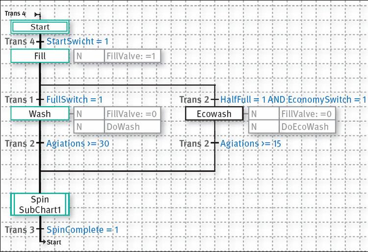
Когда выгодно
использовать SFC?
SFC –это мощный
графический язык, способен ли он заменить
другие языки программирования? Нет. SFC
относится к остальным МЭК языкам с
большим
почтением и
максимально полезен при совместном
использовании. LD
лаконичен и эффективен для работы с
Булевой логикой и управления под
задачами. ST
удобен для математических вычислений,
организации условных переходов и циклов.
Применение широко известных LD
и ST
для описания Переходов и Действий
стократ усиливает эффект использования
визуально понятного языка SFC. Во многих
системах SFC идеален с точки зрения обзора
системы: отображение на одной диаграмме
всех ключевых элементов, мониторинг
переменных, возможность свернуть часть
диаграммы в Подпрограмму. При более
глубоком программировании он может
быть полезен для коммуникации с внешними
устройствами, когда необходимо передавать
последовательность команд в зависимости
от получаемого отклика. Следовательно,
SFC может применяться всюду, где требуется
последовательный контроль процессами.
SFC: Удобства
разработки
Спрос и требования
на системы управления постоянно растет.
В больших проектах с множеством
подрядчиков встает вопрос о коммуникации
между подсистемами. Используя SFC можно
выстроить архитектуру протекания
процессов в системе и разделить сферы
ответственности каждого участника
проекта. Последовательность Функциональных
Диаграмм (SFC) зачастую реально соответствует
последовательности протекания процессов
на объекте, так хорошо знакомых конечному
пользователю. Каждый элемент SFC определяет
некоторые операции, описывает работу
отдельного узла. Использование
Функциональных Блоков ( FBD)
и объектно-ориентированных методов
программирования поможет грамотно
распределить процессы по задачам и
обеспечить целостность данных всей
системы. Значительной экономии на
времени и затратах при разработке
помогает добиться мультизадачность
программы ПЛК.
SFC: Удобство
обслуживания
Интуитивный и
легко читаемый интерфейс SFC часто
называют ‘самодокументируемым’.
Инженеры по эксплуатации могут легко
идентифицировать ошибку и устранить
проблему. Наглядный дизайн в купе с
простым мониторингом данных сокращает
время проведения внеплановых работ.
SFC для повторного
использования.
SFC позволяет легко
использовать готовые и оттестированные
блоки в новых проектах. Таким образом,
можно создать собственную библиотеку
блоков, Подпрограмм, Действий и постоянно
использовать ее элементы. Частым
заблуждением является мнение, что
‘стандартное программирование’
означает ‘стандартные программы’, и
что одна SFC программа может все, в то
время как у каждого производителя/конечного
клиента собственные требования к
технологии и создаваемым объектам. В
данном случае, повторное использование
SFC блоков уместно при тиражировании
систем одним клиентом, а так же при
реализации отдельных, схожих процессов
на объектах у различных клиентов.
Резюме
-
Выгодно использовать
SFC как‘ Верхний’ уровень программирования,
т.е. как точки отсчета при проектировании,
распределении данных, и на стадиях где
необходим последовательный контроль
над процессами. -
Использование
SFC сокращает усилия на разработку и
делает успешным взаимодействие между
подсистемами больших комплексных
проектов с участием нескольких
организаций. -
SFC само документирует
и сокращает время обслуживания. Программы
на SFC трудно адаптируемы для различных
производителей и объектов.
Ссылки
-
Смотри “CX-Programmer
Руководство Пользователя” для более
детального понимания процесса создания
SFC диаграмм в CX-Programmer. -
R. W. Lewis
“Programming industrial control systems using IEC 1131”
замечательная книга в деталях обо всех
языках стандарта МЭК 61131-3, включая SFC.
ISBN 0-85296-950-3. -
Больше информации
по МЭК 61131 можно почерпнуть с сайта
PLCOpen (www.plcopen.org) или сайта МЭК (http://iec.ch).
Конечно, информация там носит технический
характер и напрямую не предназначена
для инженеров по системам управления.
Словарь
Действие — Элемент
SFC, описывающий ‘действие’ или выполняемую
операцию в течение шага программы
МЭК — Международная
Электротехнический Комиссия, орган
стандартизации
МЭК1131 — Старое
названи МЭК61131 до смены системы присвоения
номеров в МЭК
МЭК61131 — Стандарт
МЭК для Программируемых Логических
Контроллеров (ПЛК)
Релейно-Контактная
Схема (LD)
— Базовый язык программирования для
ПЛК, другое название–язык Лестничных
диаграмм.
ПЛК — Программируемый
Логический Контроллер, устройство с
возможностью реализации логики и функций
управления под конкретные нужды.
PLCOpen — Организация
по обсуждению открытых стандартов ПЛК
SFC — Последовательность
функциональных диаграмм, графический
язык программирования стандарта МЭК
Шаг — Ключевой
элемент SFC, обозначающий конкретную
часть программы. Программа SFC при
выполнении последовательно переходит
от Шага к Шагу
Структурный текст
— Текстовый язык программирования
стандарта МЭК 61131, очень похож на язык
PASCAL
Переход — Элемент
SFC, который определяет условие передачи
разрешения на работу с одного Шага на
другой.
Соседние файлы в предмете [НЕСОРТИРОВАННОЕ]
- #
- #
- #
- #
- #
- #
20.04.2015377.86 Кб810.doc
- #
- #
- #