- Manuals
- Brands
- rotork Manuals
- Valve Positioners
- YT-3300 Series
- Product manual
-
Contents
-
Table of Contents
-
Bookmarks
Quick Links
SMART POSITIONER
YT-3300 / 3350 SERIES (PROFIBUS PA & FOUNDATION FIELDBUS)
YT-3300 (PA/FF)
YT-3350 (PA/FF)
VERSION 1.00
PRODUCT MANUAL
Rotork YTC Limited
Related Manuals for rotork YT-3300 Series
Summary of Contents for rotork YT-3300 Series
-
Page 1
SMART POSITIONER PRODUCT MANUAL YT-3300 / 3350 SERIES (PROFIBUS PA & FOUNDATION FIELDBUS) YT-3300 (PA/FF) YT-3350 (PA/FF) Rotork YTC Limited VERSION 1.00… -
Page 2: Table Of Contents
Smart Positioner YT-3300 / 3350 series (Profibus PA & Foundation Fieldbus) Product Manual Contents Introduction …………………………5 General Information for the users ………………….5 Manufacturer Warranty …………………….5 Explosion Proof Warning (Only for Intrinsic safety type positioners) …………6 Product Description ………………………7 General …………………………7 Main Features and Functions …………………..7 Label Description ……………………..8 Product Code ……………………….9…
-
Page 3
Smart Positioner YT-3300 / 3350 series (Profibus PA & Foundation Fieldbus) Product Manual Connection ……………………….29 Ground …………………………. 30 Adjustments ……………………….. 31 A/M switch adjustment ……………………31 Orifice Installment ……………………..32 Maintenance ……………………….. 33 Supply air ……………………….33 Seals …………………………33 Typical connection of YT-3300 with Profibus PA and Foundation Fieldbus …….. -
Page 4
Smart Positioner YT-3300 / 3350 series (Profibus PA & Foundation Fieldbus) Product Manual 9.8.7 Acting Type (SINGLE / dOUBLE) ………………..50 9.8.8 Lever Type (STd / AdT) ……………………. 51 Diagnostic (dIAGNO) ……………………. 52 9.9.1 Diagnosis Limit Configuration (LIMT CFG) ………………52 9.9.1.1 Deviation (dEV) …………………… -
Page 5: Introduction
Introduction General Information for the users Thank you for purchasing Rotork YTC Limited products. Each product has been fully inspected after its production to offer you the highest quality and reliable performance. Please read the product manual carefully prior to installing and commissioning the product.
-
Page 6: Explosion Proof Warning (Only For Intrinsic Safety Type Positioners)
Smart Positioner YT-3300 / 3350 series (Profibus PA & Foundation Fieldbus) Product Manual Explosion Proof Warning (Only for Intrinsic safety type positioners) Please ensure the unit is being used and installed in conformity with local, regional, and national explosion proof within the proper safety barrier environment. ➢…
-
Page 7: Product Description
Smart Positioner YT-3300 / 3350 series (Profibus PA & Foundation Fieldbus) Product Manual Product Description General YT-3300 / 3350 (PA/FF) series Smart Valve Positioner accurately controls valve stroke in response to an input signal of Communication from the controller. Built-in micro-processor optimizes the positioner’s performance and provides unique functions such as Auto-Calibration, Profibus PA or Foundation fieldbus Protocol Communications.
-
Page 8: Label Description
Smart Positioner YT-3300 / 3350 series (Profibus PA & Foundation Fieldbus) Product Manual Label Description • MODEL : Indicates the model number and additional options. • INTRINSIC SAFETY / NONINCENDIVE : Indicates intrinsic safety explosion proof grade. • INGRESS PROTECTION : Indicates enclosure protection grade. •…
-
Page 9: Product Code
Smart Positioner YT-3300 / 3350 series (Profibus PA & Foundation Fieldbus) Product Manual Product Code YT-3300 / 3350 (PA/FF) series follows suffix symbols as follows. 2.4.1 YT-3300 / 3350 1 Linear (Positioner is attached the right yoke of actuator.) Motion Type Rotary Single Acting type…
-
Page 10: Product Specification
2 kg (4.4 lb) 5.1 kg (11.2 lb) Painting Polyester Powder Coating Tested under ambient temperature of 20 °C, absolute pressure of 760 mmHg, and humidity of 65 %. Please contact Rotork YTC Limited for detailed testing specification. Ver. 1.00…
-
Page 11: Certifications
Smart Positioner YT-3300 / 3350 series (Profibus PA & Foundation Fieldbus) Product Manual Certifications ※ All certifications below are posted on Rotork YTC Limited homepage(www.ytc.co.kr). ATEX ➢ Type : Intrinsic safety Rating : II 2G Ex ia IIC T5/T6 Gb, II 2D Ex ia IIIC T100°C/T85°C Db, IP6X Certification No.
-
Page 12: Parts And Assembly
Smart Positioner YT-3300 / 3350 series (Profibus PA & Foundation Fieldbus) Product Manual Parts and Assembly Fig. 2-1: exploded view 1. Base Cover 8. Pilot Block 2. PCB Cover 9. Base body 3. Main PCB 10. Feedback Lever 4. Torque Motor 11.
-
Page 13: Product Dimension
Smart Positioner YT-3300 / 3350 series (Profibus PA & Foundation Fieldbus) Product Manual Product Dimension YT-3300 2.8.1 Fig. 2-2: YT-3300L (Standard Lever Type) Fig. 2-3: YT-3300L (Adapter Lever Type) Fig. 2-4: YT-3300R (Fork lever Type) Fig. 2-5: YT-3300 (Namur Type) Ver.
-
Page 14
Smart Positioner YT-3300 / 3350 series (Profibus PA & Foundation Fieldbus) Product Manual YT-3350 2.8.2 Fig. 2-6: YT-3350L (Standard Lever Type) Fig. 2-7: YT-3350L (Adapter Lever Type) Fig. 2-8: YT-3350R (Fork lever Type) Fig. 2-9: YT-3350R (Namur Type) Ver. 1.00… -
Page 15: Installation
Smart Positioner YT-3300 / 3350 series (Profibus PA & Foundation Fieldbus) Product Manual Installation Safety When installing a positioner, please ensure to read and follow safety instructions. ➢ Any input or supply pressures to valve, actuator, and / or to other related devices must be turned off.
-
Page 16: Linear Positioner Installation
Smart Positioner YT-3300 / 3350 series (Profibus PA & Foundation Fieldbus) Product Manual Linear positioner Installation Linear positioner should be installed on linear motion valves such as globe or gate type which uses spring return type diaphragm or piston actuators. Linear positioner Installation of Standard lever type 3.3.1 Fig.
-
Page 17: 3.3.1.2 Standard Lever Type Positioner Installation Steps
Smart Positioner YT-3300 / 3350 series (Profibus PA & Foundation Fieldbus) Product Manual 3.3.1.2 Standard lever type positioner Installation Steps 1) Assemble the positioner or remote sensor with the bracket made in previous step by fastening the bolts. Fig. 3-3: Standard Lever Type 2) Attach the positioner (or remote sensor) with the bracket to the actuator yoke –…
-
Page 18
Smart Positioner YT-3300 / 3350 series (Profibus PA & Foundation Fieldbus) Product Manual 5) Insert the connection bar between the feedback lever and lever spring. The connection bar must be located upward from the lever spring as shown below left figure. If it is located downward from the lever spring as shown below right figure, the connection bar or the lever spring will be worn out quickly because of excessive strong tension. -
Page 19
Smart Positioner YT-3300 / 3350 series (Profibus PA & Foundation Fieldbus) Product Manual 7) Check the valve stroke. The stroke numbers are engraved on the feedback lever of the positioner. Position the connection bar at the number on the feedback lever which corresponds with the desired valve stroke. -
Page 20: Installation Of Adapter Lever Type (On Tubeless Actuator)
Smart Positioner YT-3300 / 3350 series (Profibus PA & Foundation Fieldbus) Product Manual Installation of Adapter lever type (on tubeless actuator) 3.3.2 Installation of adapter lever type example Fig. 3-9: Before proceeding with the installation, ensure following components are available. ➢…
-
Page 21: 3.3.2.2 Adapter Lever Type Positioner Installation Steps
Smart Positioner YT-3300 / 3350 series (Profibus PA & Foundation Fieldbus) Product Manual 3.3.2.2 Adapter lever type positioner Installation Steps 1) Remove Out1 Plug(Fig. 3-11) on the bottom of the positioner. Plug up out1 port of gauge block with 1/4 plug using sealant. 2) Check the valve stroke.
-
Page 22
Smart Positioner YT-3300 / 3350 series (Profibus PA & Foundation Fieldbus) Product Manual Fig. 3-12: Adapter Lever Type 5) Connect Air-filter regulator to Supply port of the positioner. 6) Turn the Auto/Manual switch counterclockwise (toward “M”). Refer to 6.1 for more detail. Supply enough air pressure to the actuator in order to position the valve stroke at 50 % of the total stroke. -
Page 23: Rotary Positioner Installation
Smart Positioner YT-3300 / 3350 series (Profibus PA & Foundation Fieldbus) Product Manual Rotary positioner Installation Rotary positioner should be installed on rotary motion valve such as ball or butterfly type which uses rack and pinion, scotch yoke or other type of actuators which its stem rotates 90 degrees. Before proceeding with the installation, ensure following components are available.
-
Page 24: Rotary Bracket Information
Smart Positioner YT-3300 / 3350 series (Profibus PA & Foundation Fieldbus) Product Manual Rotary Bracket Information 3.4.2 The rotary bracket set (included with the positioner) contains two components. (but the upper brackets of Fork lever type and Namur type are different.) The bracket is designed to fit onto the actuator with 20 mm, 30 mm and 50 mm stem height (H) according to VDI/VDE 3845 standard.
-
Page 25: Rotary Positioner Installation Steps
Smart Positioner YT-3300 / 3350 series (Profibus PA & Foundation Fieldbus) Product Manual Fig. 3-16: Actuator stem Height Fig. 3-17: Exploded Brackets Rotary positioner Installation Steps 3.4.3 1) Please check the actuator’s stem height and adjust the brackets by referring to the above bracket table.
-
Page 26
Smart Positioner YT-3300 / 3350 series (Profibus PA & Foundation Fieldbus) Product Manual 5) (Only Fork lever type) After setting fork lever position, fasten lock nuts which are located on the bottom of the fork lever. Ensure to set the gap between the top of upper bracket and the top of the fork lever within 23 ~ 28 mm. -
Page 27: Connection — Air
Always recommended to use air filter regulator (i.e. YT-200 series). ➢ ➢ Rotork YTC Limited has not tested positioner’s operation with any other gases other than clean air. Please contact Rotork YTC Limited for any questions. Supply Pressure Condition ➢…
-
Page 28: Connection — Piping With Actuator
Smart Positioner YT-3300 / 3350 series (Profibus PA & Foundation Fieldbus) Product Manual Connection – Piping with actuator Single acting actuator 4.4.1 Singe acting type positioner is set to use only OUT1 port. OUT1 port of positioner should be connected with supply port of actuator when using spring return actuator of single acting type.
-
Page 29: Connection — Power
Smart Positioner YT-3300 / 3350 series (Profibus PA & Foundation Fieldbus) Product Manual Connection – Power Safety ➢ There are two conduit entries on the product. See “2.4 Product Code” for conduit entry threads. Before connecting terminal, ensure that the power is off completely. ➢…
-
Page 30: Ground
Smart Positioner YT-3300 / 3350 series (Profibus PA & Foundation Fieldbus) Product Manual Ground 1) Ground must be done before operating the positioner. 2) Open base cover and there is an internal ground “F.G” on the left hand. An external ground bolt is located next to the conduit entry. Please make sure that the resistance is less than 100 ohm.
-
Page 31: Adjustments
Smart Positioner YT-3300 / 3350 series (Profibus PA & Foundation Fieldbus) Product Manual Adjustments A/M switch adjustment 1) On the right hand bottom of positioner, there is A/M switch (Auto/Manual). A/M Switch allows the positioner to be functioned as by-pass. If the switch is turned clockwise (toward “A”) and it is fasten tightly, then the supply pressure will be transferred to actuator through outport by positioner control.
-
Page 32: Orifice Installment
Smart Positioner YT-3300 / 3350 series (Profibus PA & Foundation Fieldbus) Product Manual Orifice Installment Hunting can be occurred when the actuator’s volume is too small. In order to prevent hunting, orifice can be used. By installing the plate type orifice, the flow rate of the supply pressure to actuator can be reduced.
-
Page 33: Maintenance
Smart Positioner YT-3300 / 3350 series (Profibus PA & Foundation Fieldbus) Product Manual Maintenance Supply air If Supply air pressure is not stable or Supply air is not clean, the positioner may not function properly. Air quality and pressure should be checked regularly to see if the air is clean and pressure set is normal. Seals Once a year, it is recommended to check if there are any damaged parts of the positioner.
-
Page 34: Typical Connection Of Yt-3300 With Profibus Pa And Foundation Fieldbus
Smart Positioner YT-3300 / 3350 series (Profibus PA & Foundation Fieldbus) Product Manual Typical connection of YT-3300 with Profibus PA and Foundation Fieldbus Profibus PA The diagram below shows how to connect YT-3300 PA using EDD for Simens SIMATIC PDM. Commands from the host PC are transmitted to the DP/PA coupler through the Profibus DP interface module, and then converted into low-speed signals and transmitted to the positioner.
-
Page 35: Configurations For High Speed Solution & Low Speed Solution
Smart Positioner YT-3300 / 3350 series (Profibus PA & Foundation Fieldbus) Product Manual Configurations for high speed solution & low speed solution Fig. 8-2: High Speed solution with Profibus PA Link & Low speed solution with DP/PA coupler Foundation Fieldbus YT-3300 is connected to junction box of Foundation Fieldbus HI bus system (31.25 kbps) and its signals are transmitted to HSE (High Speed Ethernet) through Fieldbus controller (or linking device).
-
Page 36: Auto Calibration And Pcb Operation
Smart Positioner YT-3300 / 3350 series (Profibus PA & Foundation Fieldbus) Product Manual Auto Calibration and PCB Operation Warning Following process will operate valve and actuator. Before proceeding with any Auto Calibration, please separate valve from the entire system by using bypass valve, so Auto Calibration will not affect entire valve process.
-
Page 37: Auto Calibration Mode (Auto Cal)
Smart Positioner YT-3300 / 3350 series (Profibus PA & Foundation Fieldbus) Product Manual ※ By pressing <ESC> button several times from any MODES, it will return to “RUN PV” mode. Therefore, if the users have entered the wrong mode by mistake or do not wish to proceed with their current work, they could return to “RUN PV”…
-
Page 38: Auto2 Calibration (Auto2)
Smart Positioner YT-3300 / 3350 series (Profibus PA & Foundation Fieldbus) Product Manual AUTO2 Calibration (AUTO2) 9.4.2 AUTO2 changes all of the parameters. It is recommended to perform AUTO2 when the positioner has been installed on the valve for the first time or the positioner has been reinstalled after disassemble from an actuator.
-
Page 39: Manual Mode (Manual)
Smart Positioner YT-3300 / 3350 series (Profibus PA & Foundation Fieldbus) Product Manual Manual Mode (MANUAL) Manual mode is used to manually raise or lower the valve stem. In the manual mode, the positioner does not control the valve according to the electric signal inputted from the outside but the stroke of the valve can be adjusted only by the operation of <UP>…
-
Page 40: Dead-Zone (Deadzone, %)
Smart Positioner YT-3300 / 3350 series (Profibus PA & Foundation Fieldbus) Product Manual Dead-Zone (dEAdZONE, %) 9.6.1 Dead-Zone indicates the percentage of error allowance. In case of high level of packing friction, which may cause hunting, increasing the value of Dead-Zone can stable the valve operation. 3 seconds →…
-
Page 41: I Value (Ki)
Smart Positioner YT-3300 / 3350 series (Profibus PA & Foundation Fieldbus) Product Manual I Value (KI) 9.6.3 I value indicates the additional compensation signal based on the percentage of error allowance. As the value increase, it is more likely to have hunting. As the value decreases, the positioner will move slowly to the target position.
-
Page 42: Kf Up Value (Kfup)
Smart Positioner YT-3300 / 3350 series (Profibus PA & Foundation Fieldbus) Product Manual KF Up Value (KFUP) 9.6.6 KF Up control value corrects valve friction when moving from 0 % to 100 %, reducing the dead time. <UP>/<DOWN> → → →…
-
Page 43: Control Mode (Ctrl)
Smart Positioner YT-3300 / 3350 series (Profibus PA & Foundation Fieldbus) Product Manual Control mode (CTRL) 9.6.8 This function is used to select the PID tuning set that already stored corresponding to the stability or responsiveness, not in the way the user changes the KP, KI, or KD manually. •…
-
Page 44: Hand Calibration Mode (Hand Cal)
Smart Positioner YT-3300 / 3350 series (Profibus PA & Foundation Fieldbus) Product Manual Hand Calibration Mode (HAND CAL) Hand Calibration mode is used when the zero-point or end point of the valve is required to be readjusted after Auto Calibration has been performed. Zero-Point (PV ZERO) and End-Point (PV END) for Valves 9.7.1 PZ ZERO adjusts the zero point of the valve, and PV END adjusts the end point of the valve.
-
Page 45: Valve Mode (Valve)
Smart Positioner YT-3300 / 3350 series (Profibus PA & Foundation Fieldbus) Product Manual Valve Mode (VALVE) Valve mode offers useful and various function settings for operating the control valve. Below is the list of functions which could be set from Valve mode. 1) Acting Adjustment (ACT RA / dA) 2) Characteristic Adjustment (CHAR) 3) User Characteristics (USER SET)
-
Page 46: Valve Flow Characteristic Adjustment (Char)
Smart Positioner YT-3300 / 3350 series (Profibus PA & Foundation Fieldbus) Product Manual Valve flow Characteristic Adjustment (CHAR) 9.8.2 The valve flow characteristic can be set on the field’s requirement. There are 4 types of characteristics – linear (LIN), user setting (USR), quick open (QO), and equal percentage (EQ).
-
Page 47: User Defining Flow Characteristics (User Set)
Smart Positioner YT-3300 / 3350 series (Profibus PA & Foundation Fieldbus) Product Manual User defining flow Characteristics (USER SET) 9.8.3 User can make its own flow characteristic curve with this mode. USER SET can be set in two ways, 5 points and 11 points.
-
Page 48
Smart Positioner YT-3300 / 3350 series (Profibus PA & Foundation Fieldbus) Product Manual 2) 11 points setting can be set with 1mA intervals. The initial positions are P0(0 %), P1(10 %), P2(20 %), … P9(90 %) and P10(100 %) but user can change the % values to different values. User can change all 11 points or only change partially and exit the menu by pressing <ESC>… -
Page 49: Tight Shut Open (Tshut Op)
Smart Positioner YT-3300 / 3350 series (Profibus PA & Foundation Fieldbus) Product Manual Tight Shut Open (TSHUT OP) 9.8.4 Tight shut open shows the current value in percentage (%). Input current of 4 mA is 0 %, 20 mA is 100 %.
-
Page 50: Interpolation Mode (Itp On/Off, Itp User Set)
Smart Positioner YT-3300 / 3350 series (Profibus PA & Foundation Fieldbus) Product Manual Interpolation Mode (ITP ON/OFF, ITP USER SET) 9.8.6 In case of linear positioner, the error of accuracy occurs when the linear motion of actuator changes into the rotary motion of feedback lever. After the auto calibration, the positioner turns on ITP function with an appropriate value of interpolation automatically.
-
Page 51: Lever Type (Std / Adt)
Smart Positioner YT-3300 / 3350 series (Profibus PA & Foundation Fieldbus) Product Manual Lever Type (STd / AdT) 9.8.8 Displays or changes current lever type into standard type or adapter type. If the Lever type mode is set correctly, the accuracy will be worse at ITP ON than at ITP OFF. <UP>/<DOWN>…
-
Page 52: Diagnostic (Diagno)
Smart Positioner YT-3300 / 3350 series (Profibus PA & Foundation Fieldbus) Product Manual Diagnostic (dIAGNO) Below is the list of functions which could be set from Diagnostic mode. 1) Diagnosis Limit Configuration (LIMT CFG) Deviation (dEV) Deviation Time (dEV TIME) C.
-
Page 53: Deviation (Dev)
Smart Positioner YT-3300 / 3350 series (Profibus PA & Foundation Fieldbus) Product Manual 9.9.1.1 Deviation (dEV) This is used to set the deviation in % between the target position and actual position. Default is 10 %. Alarm is triggered if actual deviation greater than the preset deviation “dEV” persists longer than the preset Deviation Time “dEV TIME”.
-
Page 54: Travel Accumulator Limit (Tvla Lmt)
Smart Positioner YT-3300 / 3350 series (Profibus PA & Foundation Fieldbus) Product Manual 9.9.1.3 Travel Accumulator Limit (TVLA LMT) Travel Accumulator Alarm is triggered when total valve travel accumulated exceeds this Travel Accumulator Limit “TVLA LMT”. <UP>/<DOWN> → → → Press <UP>…
-
Page 55: Low Low Limit Alarm (Ll Alrm) And High High Limit Alarm (Hh Alrm)
Smart Positioner YT-3300 / 3350 series (Profibus PA & Foundation Fieldbus) Product Manual 9.9.1.5 Low Low Limit Alarm (LL ALRM) and High High Limit Alarm (HH ALRM) This is used to set a position to trigger Low Low Limit Alarm or High High Limit Alarm when the valve moves to the position lower than LL ALRM or higher than HH ALRM.
-
Page 56: Pst Introduction
Smart Positioner YT-3300 / 3350 series (Profibus PA & Foundation Fieldbus) Product Manual PST Introduction 9.9.2 Unlike FST (Full Stroke Test) where a valve is fully closed and opened, PST (Partial Stroke Test) is a method used to test a percentage of the possible failure of the valve by slightly closing and opening the valve.
-
Page 57: Pst Mode (Pst)
Smart Positioner YT-3300 / 3350 series (Profibus PA & Foundation Fieldbus) Product Manual PST Mode (PST) 9.9.3 To run PST, select a PST mode. There are 3 mode for running PST. Mode Description PST OFF Turn off PST. It’s a default mode Run PST once immediately.
-
Page 58: Start Position (Start Po)
Smart Positioner YT-3300 / 3350 series (Profibus PA & Foundation Fieldbus) Product Manual 9.9.4.1 Start Position (START PO) It is used to set a start position when PST initiates. The position must be in between 0 and 100 %, and default value is 100 %.
-
Page 59: Interval (Interval)
Smart Positioner YT-3300 / 3350 series (Profibus PA & Foundation Fieldbus) Product Manual 9.9.4.4 Interval (INTERVAL) Interval time (days) between 1 PST and the next PST. The value must be between 1 ~ 365, and default value is 365 (days). <UP>/<DOWN>…
-
Page 60: Latency (Latency)
Smart Positioner YT-3300 / 3350 series (Profibus PA & Foundation Fieldbus) Product Manual 9.9.4.7 Latency (LATENCY) Latency for next movement after valve move. The value must be between 1 ~ 60 sec, and default value is 10 (sec). <UP>/<DOWN> → →…
-
Page 61: View Mode (View)
Smart Positioner YT-3300 / 3350 series (Profibus PA & Foundation Fieldbus) Product Manual View Mode (VIEW) 9.10 Displays various information of the positioner. <DOWN> 3 seconds → → → Press <UP> or <DOWN> button if the above is not displayed. <DOWN>…
-
Page 62
Smart Positioner YT-3300 / 3350 series (Profibus PA & Foundation Fieldbus) Product Manual bIAS 25 BIAS value when valve position is at 25 % bIAS 75 BIAS value when valve position is at 75 % Total operation time. If the device is used for less than 1 hour, the time does not accumulate. -
Page 63: Warning / Alarm Code
Smart Positioner YT-3300 / 3350 series (Profibus PA & Foundation Fieldbus) Product Manual Warning / Alarm Code This is the status and alarm code displayed on the LCD screen when a change in the state of the product and process occurs while using the product. Please refer to the table below to check the code for the status and alarm and take the appropriate action.
-
Page 64
Smart Positioner YT-3300 / 3350 series (Profibus PA & Foundation Fieldbus) Product Manual Category Alarm Code Code Description and Cause Action ➢ Displayed when the valve does not move even though the positioner sends “Full Open” signal during ➢ Check if air pressure is Auto Calibration. -
Page 65
Smart Positioner YT-3300 / 3350 series (Profibus PA & Foundation Fieldbus) Product Manual Warning Category Code Description and Cause Action Code ➢ Warning is triggered when the actual position (PV) is lower than ➢ Make sure that the «LO setting in «LO ALARM». LO ALRM ALRM»… -
Page 66: Main Software Map
Smart Positioner YT-3300 / 3350 series (Profibus PA & Foundation Fieldbus) Product Manual Main Software Map Ver. 1.00…
-
Page 67
Product Manual Manufacturer: Rotork YTC Limited Address: 81, Hwanggeum-ro, 89 Beon-gil, Yangchon-eup, Gimpo-si, Gyeonggi-do, South Korea Postal code: 10048 Tel: +82-31-986-8545 Fax: +82-70-4170-4927 Email: ytc.sales@rotork.com Homepage : http://www.ytc.co.kr Issued : 2021-01-21 Copyright © Rotork YTC Limited. All Rights Reserved. Ver. 1.00…
|
Download 1.69 Mb. Pdf ko’rish
|
Bog’liq
SmartPositioner.en.ru
Tadbirkorlik faoliyati tushunchasi va uning vazifalari, Texnika xavfsizligi, Texnika xavfsizligi, Leksiya-4, Тема 18, guide interview, план, Qarorlarni boshqalar bilan bo`lishish va ularni ergashtirish., 196 guruh ro‘yhat, Урганч шаҳридагиq2, Servis faoliyatini tushunchasi va mohiyati. Servis faoliyatini ahamiyati va rivojlanish istiqbollari, Kurs ishining maqsadi, Texnikaviy o`lchovlar, o`lchov vositalari va usullari haqida asosiy tushunchalar., Avgust-Oktyabr PED kengash ATTESTATSIYA 3-MAKTAB, 5-SINF Informatika va AT
- Bu sahifa navigatsiya:
- Содержание 1. Введение ……………………………………………………………………………………………
- 2. Описание продукта …………………………………………………………………………………..
- 3. Установка………………………………………………………………………………………………. 13
- 4. Соединения………………………………………………………………………………………………………………………………………………………………………………………………………………………………………………………………………………………………………………………………………………………………………………………………………………………………………………………………………….
УМНЫЙ ПОЗИЦИОНЕР
СЕРИЯ YT-3300/3301
ИНСТРУКЦИЯ ПО ИСПОЛЬЗОВАНИЮ
ВЕРСИЯ 1.02
Перевод: английский — русский — www.onlinedoctranslator.com
Содержание
1. Введение ……………………………………………………………………………………………
1.1 Общая информация для пользователей ………………………………………………………………….
1.2 Гарантия производителя ……………………………………………………………………………
2. Описание продукта …………………………………………………………………………………..
2.1 Общие ……………………………………………………………………………………………………………………………………………………………………………………
2.2 Основные характеристики и функции ……………………………………………………………………….
2.3 Описание этикетки …………………………………………………………………………………………………………………………………………………………………………………
2.4 Номер продукта ……………………………………………………………………………………
2.5 Спецификация продукта ………………………………………………………………………………
2.6 Детали и сборка – YT-3300L и YT-3300R…………………………………………………..
2.7 Детали и сборка – YT-3301L и YT-3301R ………………………………………………….. 10
2.8 Размер продукта …………………………………………………………………………………………………………………………………………………………………………………………………………………………………………………………………………………………………………………………………………………………………………………………………………………………………………………………………………………………………………………………………………… 10
2.8.1 YT-3300L………………………………………………………………………………… 10
2.8.2 YT-3300R ………………………………………………………………………………… 11
2.8.3 YT-3301L ………………………………………………………………………………… 12
2.8.4 YT-3301R ………………………………………………………………………………… 12
3. Установка………………………………………………………………………………………………. 13
3.1 Безопасность …………………………………………………………………………………………….. 13
3.2 Установка YT-3300/3301L …………………………………………………………………… 13
3.2.1 Этапы установки ………………………………………………………………………… 13
3.3 YT-3300L Установка прямого монтажа …………………………………………………………… .. 15
3.3.1 Этапы установки ………………………………………………………………………… 15
3.4 Установка YT-3300R …………………………………………………………………………… 16
3.4.1 Информация о кронштейне ……………………………………………………………………… … 16
4. Соединения………………………………………………………………………………………………………………………………………………………………………………………………………………………………………………………………………………………………………………………………………………………………………………………………………………………………………………………………………….
4.1 Безопасность ……………………………………………………………………………………………………………………………………………………………………………………………………………………………………………………………………………………………………………………………………………………………………………………………………………………………………………………………………………………………………………………………………………………………………………….. 17 17
4.2 Состояние давления подачи ……………………………………………………………………….. 17
4.3 Состояние трубопроводов……………………………………………………………………………………………………………………………………………………………………………… 17
4.4 Соединение – привод ………………………………………………………………………………………………………………………………………………………………………………………………………………………………………………………………………………………………………………………………………………………………………………………………………………………………………………………………………………………………………………………………………………………………………………………………………………………………………………………………………………………………………………………………………………………………………………………18
4.4.1 Привод одностороннего действия – YT-3300……………………………………………………… 18
4.4.2 Привод двойного действия – YT-3300……………………………………………………….. 18
4.4.3 Привод одностороннего действия – YT-3301 …………………………………………………………………………………………………………………………………………………………………………………………………………………………………………………………………………………………………………………………………………………………………………………………………………………………………………………………………………………………………………………………………………………………………………………………………………………………………………………………………………………………… 18
4.4.4 Привод двойного действия – YT-3301 ……………………………………………………….. 19
4.5 Подключение – питание………………………………………………………………………………………………………………………………………………………………………………………………………………………………………………………………………………………………………………………………………………………………………………………………………………………….. 19 19
4.5.1 Безопасность ……………………………………………………………………………………… … 19
4.5.2 Обзор терминала ………………………………………………………………………. 20
4.5.2.1 Клемма концевого выключателя — механический тип
………………………. 20
4.5.2.2 Клемма концевого выключателя бесконтактного типа ………………………… 21
Do’stlaringiz bilan baham:
 YT-3300 смарт-позиционеры YT-3300 смарт-позиционеры |
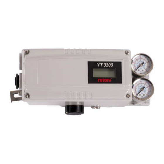
YT-3300 смарт-позиционеры YTC — необходимы для управления запорной арматурой с высокой точностью по заданному входному сигналу 4-20 мА. Модель позиционера серии 3300/3350 использует высокопроизводительный процессор, обеспечивающий возможность самостоятельной настройки (автокалибровки), изменяемый вид характеристики (линейный, равнопроцентный, быстрым открытие, иные настройки). Наличие строенного дисплея позволяет производить визуальную диагностику, изменения настроек ПИД-регулирования, а опция HART-протокола расширяет возможность передачи данный о состоянии узла в систему управления. Опционально, позиционер снабжается сигналом обратной связи 4-20мА, а также механическими или индуктивными датчиками конечных положений. По умолчанию, во всех моделях установлены пневматические дроссели, позволяющие адаптировать расход воздуха позиционера под любой тип пневматического привода. Степень защиты корпуса — IP66. YT-3300 — корпус алюминиевое литье, YT-3350 — корпус нержавеющая сталь AISI 316. Для подключения фитингов с резьбой G и R к портам подключения сжатого воздуха и манометра NPT — потребуется переходник. Опционально: взрывозащита Ex ia IIC T5/T6 Gb. Подробнее тех. данные и принадлежности для монтажа смотрите в каталоге. YT-3300 смарт-позиционеры — скачать каталог |
| Маркировка | Тип | Конструкция | Исполнение |
|---|---|---|---|
| VZAV-C | затвор поворотный | дисковый | двухстороннего действия |
| DAPS | привод поворотный | клино-рычажный | одно- / двухсторон. действия |
| DFPD | привод поворотный | рейка-шестерня | одно- / двухсторон. действия |
| Маркировка | Тип привода | Взрывозащита | Tраб. / опции управ. |
|---|---|---|---|
| YT-3300RDI5301S | поворотный, NAMUR | Ex ia IIC T5/T6 Gb | -30 — +85°C / датчик О.С. 4-20 мА |
| YT-3300RDI5320L | поворотный, NAMUR | Ex ia IIC T5/T6 Gb | -60 — +85°C / HART-протокол |
| YT-3300RDN5221S | поворотный, NAMUR | без взрывозащиты | -30 — +85°C / HART, О.С. 4-20 мА |
| YT-3300RDN5300L | поворотный, NAMUR | без взрывозащиты | -60 — +85°C / без опций |
| YT-3300RDN5300S | поворотный, NAMUR | без взрывозащиты | -30 — +85°C / без опций |
| YT-3300RDN5301S | поворотный, NAMUR | без взрывозащиты | -30 — +85°C / датчик О.С. 4-20 мА |
| YT-3300RDN5320S | поворотный, NAMUR | без взрывозащиты | -30 — +85°C / HART-протокол |
| YT-3300RDN5321S | поворотный, NAMUR | без взрывозащиты | -30 — +85°C / HART, О.С. 4-20 мА |
| Маркировка | Тип привода | Взрывозащита | Tраб. / опции управ. |
|---|---|---|---|
| YT-3300RSN1323S | поворотный, — | без взрывозащиты | -30 — +85°C/ HART, датчик полож. |
| YT-3300RSN5121S | поворотный, NAMUR | без взрывозащиты | -30 — +85°C / HART, О.С. 4-20 мА |
| YT-3300RSN5301L | поворотный, NAMUR | без взрывозащиты | -60 — +85°C / датчик О.С. 4-20 мА |
| YT-3300RSN5301S | поворотный, NAMUR | без взрывозащиты | -30 — +85°C / датчик О.С. 4-20 мА |
| YT-3300RSN5304S | поворотный, NAMUR | без взрывозащиты | -30 — +85°C/ О.С. 4-20мА + датчик |
| YT-3300RSN5321S | поворотный, NAMUR | без взрывозащиты | -30 — +85°C / HART, О.С. 4-20 мА |
| Маркировка | Тип привода | Взрывозащита | Tраб. / опции управ. |
|---|---|---|---|
| YT-3300LDI1300L | линейный, 20-100 мм | Ex ia IIC T5/T6 Gb | -60 — +85°C / без опций |
| YT-3300LDI1321L | линейный, 20-100 мм | Ex ia IIC T5/T6 Gb | -60 — +85°C / HART, О.С. 4-20 мА |
| YT-3300LDI1323L | линейный, 20-100 мм | Ex ia IIC T5/T6 Gb | -60 — +85°C/ HART, датчик полож. |
| YT-3300LDI1325L | линейный, 20-100 мм | Ex ia IIC T5/T6 Gb | -60 — +85°C/ О.С. 4-20мА + датчик |
| YT-3300LDN1501S | линейный, 20-100 мм | без взрывозащиты | -30 — +85°C / датчик О.С. 4-20мА |
| Маркировка | Тип привода | Взрывозащита | Tраб. / опции управ. |
|---|---|---|---|
| YT-3300LSI0300L | линейный, 10-40 мм | Ex ia IIC T5/T6 Gb | -60 — +85°C / без опций |
| YT-3300LSI0301L | линейный, 10-40 мм | Ex ia IIC T5/T6 Gb | -60 — +85°C / датчик О.С. 4-20мА |
| YT-3300LSI0320L | линейный, 10-40 мм | Ex ia IIC T5/T6 Gb | -60 — +85°C / HART-протокол |
| YT-3300LSI0420S | линейный, 10-40 мм | Ex ia IIC T5/T6 Gb | -30 — +85°C / HART-протокол |
| YT-3300LSI1300L | линейный, 20-100 мм | Ex ia IIC T5/T6 Gb | -60 — +85°C / без опций |
| YT-3300LSI1301L | линейный, 20-100 мм | Ex ia IIC T5/T6 Gb | -60 — +85°C / датчик О.С. 4-20мА |
| YT-3300LSI1320L | линейный, 20-100 мм | Ex ia IIC T5/T6 Gb | -60 — +85°C / HART-протокол |
| YT-3300LSI1320S | линейный, 20-100 мм | Ex ia IIC T5/T6 Gb | -30 — +85°C / HART-протокол |
| YT-3300LSI1420S | линейный, 20-100 мм | Ex ia IIC T5/T6 Gb | -30 — +85°C / HART-протокол |
| YT-3300LSI3321L | линейный, — | Ex ia IIC T5/T6 Gb | -60 — +85°C / HART, О.С. 4-20 мА |
| YT-3300LSN0300L | линейный, 10-40 мм | без взрывозащиты | -60 — +85°C / без опций |
| YT-3300LSN0300S | линейный, 10-40 мм | без взрывозащиты | -30 — +85°C / без опций |
| YT-3300LSN0301L | линейный, 10-40 мм | без взрывозащиты | -60 — +85°C / датчик О.С. 4-20мА |
| YT-3300LSN0305S | линейный, 10-40 мм | без взрывозащиты | -30 — +85°C/ О.С. 4-20мА + датчик |
| YT-3300LSN0320L | линейный, 10-40 мм | без взрывозащиты | -60 — +85°C / HART-протокол |
| YT-3300LSN0321L | линейный, 10-40 мм | без взрывозащиты | -60 — +85°C / HART, О.С. 4-20 мА |
| YT-3300LSN0323S | линейный, 10-40 мм | без взрывозащиты | -30 — +85°C/ HART, датчик полож. |
| YT-3300LSN1300L | линейный, 20-100 мм | без взрывозащиты | -60 — +85°C / без опций |
| YT-3300LSN1300S | линейный, 20-100 мм | без взрывозащиты | -30 — +85°C / без опций |
| YT-3300LSN1301S | линейный, 20-100 мм | без взрывозащиты | -30 — +85°C / датчик О.С. 4-20мА |
| YT-3300LSN1302S | линейный, 20-100 мм | без взрывозащиты | -30 — +85°C / датчики положения |
| YT-3300LSN1320L | линейный, 20-100 мм | без взрывозащиты | -60 — +85°C / HART-протокол |
| YT-3300LSN1321L | линейный, 20-100 мм | без взрывозащиты | -60 — +85°C / О.С. 4-20 мА |
| YT-3300LSN1321S | линейный, 20-100 мм | без взрывозащиты | -30 — +85°C / О.С. 4-20 мА |
| YT-3300LSN1323S | линейный, 20-100 мм | без взрывозащиты | -30 — +85°C/ HART, датчик полож. |
| YT-3300LSN1401S | линейный, 20-100 мм | без взрывозащиты | -30 — +85°C / датчик О.С. 4-20мА |
Пример заказа позиционера:
YT-3300RDN5300S — смарт-позиционер электропневматический, 2-х стороннего действия, для поворотных приводов, без взрывозащиты (стандарт), тип соединения — NAMUR, кабельный ввод / пневмопорт — G1/2 / G1/4, без HART-протокола, рабочая температура: -30 — +85°C
YT-3300RDI5320L — смарт-позиционер электропневматический, 2-х стороннего действия, для поворотных приводов, взрывозащита Ex ia IIC T5/T6 Gb, тип соединения — NAMUR, кабельный ввод / пневмопорт — G1/2 / G1/4, HART-протокол, рабочая температура: -60 — +85°C
Поиск товара
|
||||||||||||||||||||||||||||||||||||||||||||||||||||||||||||||||||||||||||||||||||||||||||||||||||
|
Поворотный пневматический позиционер Серия YT-1200RЛинейный пневматический позиционер Серия YT-1200L
|


Smart Positioner
YT-3300 / 3350 series (Profibus PA & Foundation Fieldbus)
5) Connect Air-filter regulator to Supply port of the positioner.
6) Turn the Auto/Manual switch counterclockwise (toward «M»). Refer to 6.1 for more detail. Supply
enough air pressure to the actuator in order to position the valve stroke at 50 % of the total stroke.
7) Check if feedback lever is vertical to the valve stem at 50 % of the valve stroke. If it is not vertical,
adjust the adapter holder on the actuator’s stem to make vertical – DO NOT TIGHTEN THE
ADAPTER HOLDER COMPLETELY. Improper installation may cause poor linearity.
Refer to Fig 3-6.
 After installing the positioner, operate the valve from 0 % to 100 % stroke by using direct air to the
actuator. On both 0 % and 100 %, the feedback lever should not touch the lever stopper, which is
located on the backside of the positioner. If the feedback lever touches the stopper, the adapter
holder should be moved or the adapter of feedback lever should be moved further away from the
main shaft of the positioner.
Refer to Fig 3-8.
9) After the installation, tighten the adapter holder. And Turn the Auto/Manual switch clockwise
(toward «A») tightly. Refer to 6.1 for more detail.
Ver. 1.00
Fig. 3-12: Adapter Lever Type
22
Product Manual