-
Contents
-
Table of Contents
-
Troubleshooting
-
Bookmarks
Quick Links
4-740-700-11(1)
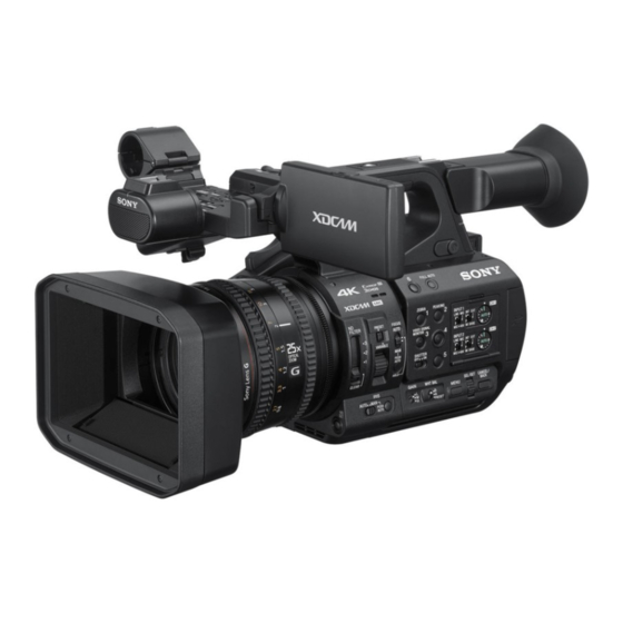
Solid-State Memory
Camcorder
Operating Instructions
Before operating the unit, please read this manual thoroughly
and retain it for future reference.
PXW-Z190V/PXW-Z190T
© 2018 Sony Corporation
Related Manuals for Sony PXW-Z190V
Summary of Contents for Sony PXW-Z190V
-
Page 1
4-740-700-11(1) Solid-State Memory Camcorder Operating Instructions Before operating the unit, please read this manual thoroughly and retain it for future reference. PXW-Z190V/PXW-Z190T © 2018 Sony Corporation… -
Page 2: Table Of Contents
Table of Contents Overview Location and Function of Parts ……….6 Main unit ……………. 6 Screen Display …………….. 11 LCD/viewfinder screen ……….11 Status screen …………..13 Preparation Power Supply …………….16 Using a battery pack …………. 16 Using AC power …………17 Turning the camcorder on/off ……..
-
Page 3
Changing Basic Settings …………25 Video format …………..25 Adjusting the brightness ……….26 Adjusting for natural colors (white balance) ….27 Setting the audio to record ……….. 29 Image stabilization …………31 Time data …………..31 Useful Functions …………..32 Direct menu operation ………. -
Page 4
Clip Operations …………… 54 Thumbnail menu operations ……… 54 Displaying clip properties ……….55 Protecting clips …………. 56 Copying clips …………… 56 Deleting clips …………… 57 Filtering clips (frames) using the essence mark thumbnail screen ………… 57 Changing the information displayed on the thumbnail screen ………….. -
Page 5
Video Formats …………… 100 About recording media ……….100 Special recording modes and compatible formats ..100 Maximum recording time for a clip ……101 Output Formats and Limitations ……..102 Video formats and output signals ……. 102 Limitations between recording functions ….104 Troubleshooting ………….. -
Page 6: Location And Function Of Parts
Overview Location and Function of Parts For details about the usage and function of each part, see the referenced page. Main unit Hook for shoulder strap (9) Wi-Fi antenna ASSIGN7/DIRECT MENU button (34) (N mark) • Hold an NFC-compatible smartphone near this mark to establish a wireless connection between the camcorder and smartphone.
-
Page 7
Internal microphone (29) Recording/tally lamp (front) (92) Flashes when the remaining capacity on the recording media or battery is low. ASSIGN6 button FULL AUTO button (22) ND FILTER switch ND FILTER mode switch FOCUS switch (24) ASSIGN3/VIDEO SIGNAL MONITOR button ASSIGN1/ZEBRA button ASSIGN2/PEAKING button INPUT1 switch (29) -
Page 8
BATT RELEASE button (16) Note Battery pack attachment (16) • Do not cover the air inlet. Multi/Micro USB connector (59) REMOTE connector The REMOTE connector is used for controlling USB3.0 (HOST) connector (type A) start/stop of recording and other functions on the SDI OUT connector (58) video device and peripherals connected to it. -
Page 9
To attach a shoulder strap Zoom ring (24) Attach a shoulder strap to the hooks for the Focus ring (24) shoulder strap. Full MF switch (24) Switch manual focus mode on/off by moving the focus ring forward/back. Lens cover lever (18) Opens/closes the lens cover. -
Page 10
THUMBNAIL button (52) Bottom Side STOP/CAM button (53) STATUS CHECK button (13) PREV button (53) V/v/B/b/SET button (64) MENU button (64) F REV button (53) PLAY/PAUSE button (53) F FWD button (53) NEXT button (53) LCD BRIGHT button (19) DISPLAY button (11) Tripod screw holes (1/4 inch, 3/8 inch) LCD screen (19) Compatible with 1/4-20UNC screws and 3/8-… -
Page 11: Screen Display
Screen Display LCD/viewfinder screen While recording, standing by to record, or during playback, the statuses and settings of the camcorder are superimposed on the LCD/viewfinder screen. You can show/hide the information using the DISPLAY button. You can also select to show/hide each item independently (page 81). Information displayed on the screen while shooting Network status indicator (page 12) Focus mode indicator (page 33)
-
Page 12
SDI output/HDMI output Rec Control indicator Displayed when Display On/Off >SDI/HDMI Rec Control in the LCD/VF menu and SDI/ HDMI Rec Control >Setting in the Video menu are both set to On. Digital extender indicator (page 91) Focus assist indicator Media remaining capacity indicator White balance mode indicator Automatic mode… -
Page 13: Status Screen
Audio Status screen Network Connection Icon Displays the input setting, audio level meter, and mode status wind noise reduction filter setting for each Station mode Wi-Fi channel. connected CH1 level meter CH1 level meter Wi-Fi signal CH1 Input Source CH1 input source strength (4 CH1 Ref./Sens.
-
Page 14
Media Status screen Proxy Rec Proxy recording On/Off Displays the remaining space, available recording status and setting time, and estimated service life of the recording Video Output Status screen media (memory card A/memory card B) and Displays the SDI, HDMI, and video output UTILITY media. -
Page 15
UTILITY media Displays an estimate of the Setting Status Description remaining capacity remaining recording time of display display the recording media inserted Station Mode Non Active Not operating in in the UTILITY SD/MS slot station mode. in units of minutes. Or Displayed when displays the remaining Wi-Fi chip fails. -
Page 16: Power Supply
LCD/viewfinder screen For safety, use only the Sony battery packs and (page 11). AC adaptors listed below. Lithium-ion battery packs…
-
Page 17: Using Ac Power
Using AC power Turning the camcorder on/off Connecting the camcorder to a power outlet To turn the camcorder on, set the ON/STANDBY allows use without worrying about the need to switch (page
 to the ON position ([). To turn the recharge the battery pack.
 -
Page 18: Setting The Clock
Setting the Clock Attaching Devices When you turn the camcorder on for the first time Attaching the lens hood after purchasing or the backup battery has completely discharged, the initial setting display appears on the viewfinder screen and LCD screen. Set the date and time of the internal clock using this screen.
-
Page 19: Adjusting The Screens
Diopter adjustment dial Adjusting the Screens Move it until the picture becomes clear. Adjusting the LCD screen Open the LCD screen 180 degrees (1), then rotate it to the best angle to record or play back (2). 1 Open 180 degrees 2 90 degrees…
-
Page 20: Using Memory Cards
• A memory card removed from the camcorder after recording ended may be hot. This is not a malfunction. Using Memory Cards Switching between memory cards This camcorder records audio and video on memory cards (sold separately) inserted in the When memory cards are loaded in both card slots memory card slots.
-
Page 21: Checking The Remaining Recording Time
A message and progress status (%) are displayed Checking the remaining recording while formatting is in progress, and the access time lamp is lit red. When restoration ends, a completion message While recording (or standing by to record), you appears. can check the remaining space for the memory If restoration fails cards loaded in the card slots on the A/B slot…
-
Page 22: Basic Operation Procedure
Shooting Basic Operation Procedure Continuous recording on the memory Shooting cards (Relay Rec) Basic shooting is conducted using the following When memory cards are inserted in both slots A procedure. and B, recording automatically switches to the second memory card just before the remaining Attach the necessary devices, and check capacity on the first card is reduced to zero.
-
Page 23: Adjusting The Zoom
About clips Using the power zoom lever Zoom by pressing the power zoom lever C. Clip (recording data) Lightly press the power zoom lever C for a When you stop recording, video, audio, and slower zoom. Fully press it for a faster zoom. subsidiary data from the start to end of the Wide view: Wide recording are recorded as a single clip on a…
-
Page 24: Adjusting The Focus
• While in Full MF mode, the auto focus and push auto Using the zoom ring focus functions do not work. • Macro is set to off regardless of the Focus Macro Zoom by turning the zoom ring B. setting in the Camera menu. You can zoom at the desired speed by turning the zoom ring B.
-
Page 25: Monitoring Audio While Shooting
magnifier screen appears showing the part of the image magnified. Changing Basic Settings The magnification switches between 4× and 8× each time the button is pressed when the recording format is QFHD. You can move the You can change the settings based on the video magnified position using the V/v/B/b button.
-
Page 26: Adjusting The Brightness
Auto iris is active while the button is pressed. Adjusting the brightness Release the button to return to manual iris mode. Shooting with auto gain (AGC) When Full Auto mode (page 22) is on AGC (Auto Gain Control) mode is forcibly enabled.
-
Page 27: Adjusting For Natural Colors (White Balance)
Setting in the Camera menu Setting auto exposure Select Shutter (page 70) in the Camera menu and set the shutter mode and speed. Auto exposure controls excessive brightness to an appropriate level using auto ND filter, iris, gain, Setting using the direct menu and shutter functions.
-
Page 28
Memory A mode, Memory B mode Using the direct menu This mode adjusts the white balance to the setting saved in memory A or B, respectively. Press the DISPLAY button (page 10) to display Press the WB SET button A to execute auto the selected mode and color temperature on the white balance adjustment and store the adjusted screen (page 11). -
Page 29: Setting The Audio To Record
If the error message persists after repeated attempts to set white balance, contact To record on CH1, CH2 your Sony service representative. Set the CH1 (INT/EXT/MI SHOE) switch D and CH2 (INT/EXT/MI SHOE) switch Setting the audio to record G to INT.
-
Page 30
To record on CH3, CH4 Attach a microphone, then close the microphone holder to secure the Select INPUT1 using Audio Input microphone. (page 77) >CH3 Input Select and INPUT2 using CH4 Input Select in the Connect the microphone cable to the Audio menu. -
Page 31: Image Stabilization
Set SteadyShot (page 71) >Setting in the Adjusting the audio recording level Camera menu to Active or Standard. For CH1, CH2 Standard: Reduces shaking of the image due to camera movement. Adjusting automatically (AGC): Active: Reduces shaking of the image due to Set the AUDIO LEVEL (CH1/CH2) dials rapid camera movement, such as when (E/F) to the AUTO position.
-
Page 32: Useful Functions
Display Description Useful Functions UBG ** ** ** ** User bits DUR **:**:**:** Duration from the beginning of recording Direct menu operation You can check status and change settings for some items displayed directly on the LCD/ viewfinder screen. The Direct Menu function is used by assigning the function to an assignable button.
-
Page 33: Face Detection Af
Move the cursor to the desired item Notes using the V/v/B/b button or SEL/SET • During push auto focus operation, Face Priority AF is dial, and press the SET button or SEL/ activated even if Face Only AF is currently selected. •…
-
Page 34: Color Bars/Reference Audio Tone
Registered face frame Color bars/reference audio tone (double white frame) Other faces (gray) You can output color bars instead of the camera image by setting Color Bars (page 71) >Setting in the Camera menu to On. The image output is restored when set to Off.
-
Page 35: Interval Recording (Interval Rec)
• Proxy Rec Start/Stop Changing functions • Rec Review Use Assignable Button (page 91) in the System • Last Clip Delete menu. • Thumbnail You can view the assigned functions on the • NFC Assignable Button Status screen (page 14). •…
-
Page 36: Continuous Recording (Clip Continuous Rec)
When a video light compatible with the Multi For details about recording formats compatible Interface Shoe is mounted, you can set Interval with Clip Continuous Rec, see (page 100). Rec >Pre-Lighting in the Recording menu to On so that the light turns on automatically 2 seconds, Configuring before shooting 5 seconds, or 10 seconds before recording starts.
-
Page 37: Picture Cache Recording (Picture Cache Rec)
To cancel Picture Cache Rec mode mode. A new clip will be created when you next start recording. Set Picture Cache Rec >Setting in the Recording • Operate on a clip (lock, delete, or rename a clip) menu to Off, or press an assignable button •…
-
Page 38: Simultaneous Recording In 2 Slots (Simul Rec)
Setting the recording frame rate using the direct Rec, or S&Q Motion. When 2-slot Simul Rec is set to On, these other recording modes are forcibly set to Off. menu You can set the recording frame rate in Slow & Recording in 2-slot Simul Rec mode Quick Motion mode using the direct menu (page 32).
-
Page 39: High Dynamic Range (Hdr) Recording
• The gamma display assist function is used only for the document. LCD/viewfinder screen. The settings are not applied to Configuration data is stored in the following the recorded image or output image. directory on media. /PRIVATE/SONY/PRO/CAMERA/PXW- Z190V/ (or PXW-Z190T)
-
Page 40
Utility SD/MS >Execute in the File Formatting (initializing) media menu. SD cards and “Memory Stick” media must be A file save destination screen appears. formatted the first time they are used in the camcorder. Select a “No File” row on the save An SD card or “Memory Stick”… -
Page 41
Saving a scene file Loading a scene file To save in internal memory To load from internal memory Select Scene File >Store Internal Select Scene File >Recall Internal Memory >Execute in the File menu Memory >Execute in the File menu (page 87). -
Page 42: Acquiring Location Information (Gps)
Select a character using the V/v/B/b Positioning Display GPS reception state button or SEL/SET dial, and press the status SET button or SEL/SET dial. Positioning A weak GPS signal is being received. Repeat step 2 as required. A GPS signal is being received.
-
Page 43: Proxy Recording
Checking the remaining capacity Proxy Recording You can check the remaining capacity on an SD card on the Media Status screen (page 14). You can record proxy data on an SD card in the UTILITY SD/MS slot simultaneously while Note recording to the memory cards in the memory •…
-
Page 44: Changing Proxy Recording Settings
Example: If the timecode at the recording start Changing proxy recording settings time is “14:30:20:05” then the file name becomes “14_30_20_05.mp4”. Setting the picture size Configuring before shooting Select Proxy Rec >Proxy Format in the Recording menu, and set the picture size. Assign Proxy Rec Start/Stop to an assignable button (page 34).
-
Page 45: Connecting To Other Devices Via Lan
[NFC] checkbox. camcorder, using the “Content Browser Mobile” application. For details about the “Content Browser Mobile” application, contact your Sony sales or service representative. Connecting using wireless LAN Turn the camcorder on. access point mode Activate the NFC function.
-
Page 46: Connecting Using Wireless Lan Station Mode
Select Wireless LAN >Setting >Access Point Mode in the Network menu. Open the device Network Settings or Wi-Fi Settings on the device, and turn Wi-Fi on. Connect the device to the camcorder by selecting the camcorder SSID from the SSID list in Wi-Fi Network and entering the password.
-
Page 47
Connect the device to the access point. Smartphone/ Computer For details about connecting, refer to the tablet operating instructions of the device. Display the web remote control (page 50). Or connect using the Content Browser Mobile application. Connecting to an access point using auto network detection or manually Access You can configure connection to a desired access… -
Page 48
• IP Address access point. Input the IP address of the camcorder. This Enabled when Security is not set to None. setting is available only when DHCP is set • DHCP to Off. Set the DHCP setting. • Subnet Mask When you set to On, the IP address is Input the subnet mask of the camcorder. -
Page 49: List Of Functions For Network Connections
List of functions for network connections The following table shows the availability of network functions in each network connection mode. Network function Network connection mode Access Point Station Monitoring × (page 45) Remote control of camcorder × (page 50) 1) Functions of device connected with the camcorder via a network…
-
Page 50: Using Web Remote Control
Playback screen Using Web Remote Control You can access the web remote control built into the camcorder from a tablet or computer over a network connection. Using the web remote control allows you to operate the camcorder remotely. You can start/ stop recording and adjust the recording settings with a connected device.
-
Page 51
OS, and browsers are shown in the following table. Device Browser Tablet Android 6/7 Chrome iOS 11 Safari Computer Windows 7/8.1/ Chrome macOS 10.12/ Safari 10.13 For details about devices supported using the “Content Browser Mobile” application, contact your Sony sales or service representative. -
Page 52: Thumbnail Screen
Thumbnail Screen Configuration of the Thumbnail Screen When you press the THUMBNAIL button (page 10), clips recorded on the memory card are displayed as thumbnails on the screen. You can select a clip on the thumbnail screen and start playback of that clip. The playback picture can be seen on the LCD/viewfinder screen and external monitors.
-
Page 53: Playing Clips
Notes Playing Clips • There may be momentary picture breakup or still image display at the boundary between clips. You cannot operate the camcorder during this period. • When you select a clip in the thumbnail screen and Playing recorded clips begin playback, there may be momentary picture breakup at the start of the clip.
-
Page 54: Clip Operations
Clip Operations The Thumbnail menu is used to protect/delete clips, check properties, and other tasks. Thumbnail menu operations The Thumbnail menu can be used only when a thumbnail screen is displayed. Press the THUMBNAIL button. The thumbnail screen appears. Press the MENU button. The menu screen appears.
-
Page 55: Displaying Clip Properties
Displaying clip properties Select Display Clip Properties in the Thumbnail menu. Image of the current clip Timecode indicator TC Index: Timecode of the displayed frame Start: Timecode at the recording start point End: Timecode at the recording end point Duration: Duration of the clip Creation date and modified date Currently selected memory card Media protect icon…
-
Page 56: Protecting Clips
Press the SET button or SEL/SET dial Protecting clips to dismiss the message. You can protect a specified clip or all clips to Copying clips protect the clips from being deleted. is added to the thumbnails of protected clips. Clips can be protected on the thumbnail screen. You can copy clips to another memory card.
-
Page 57: Deleting Clips
Select Copy Clip > All Clips in the Filtering clips (frames) using the Thumbnail menu. essence mark thumbnail screen A confirmation screen appears. When a recording start mark has been recorded in Select Execute. a clip, you can display thumbnails for only those All clips are copied, and a completion frames with an added recording start mark.
-
Page 58: External Device Connection
External Device Connection Connecting External Monitors and Recording Devices To display recorded/playback pictures on an HDMI OUT connector (Type A connector) external monitor, select the camcorder output signal and use an appropriate cable for the Set the on/off setting of the output, and the output monitor to be connected.
-
Page 59: Managing/Editing Clips On A Computer
Notes Managing/Editing Clips • Do not perform the following operations if the access lamp is lit red. on a Computer Turning the power off or disconnecting the power cord Removing the memory card Disconnecting the USB cable •…
-
Page 60
Select the copy destination folder from Select the folder to rename from the the folder list, and press the SET button folder list, and press the SET button or or SEL/SET dial. SEL/SET dial. You can also select New on the screen to A file name input screen appears. -
Page 61
State Solution During clip recording, Terminate the previous playback, thumbnail display, operation. proxy recording, formatting/ restoring media, management file update, software update, camcorder resetting, network reset, computer connecting, confirmation screen display Insufficient supply voltage Change the battery or replace the input power supply. -
Page 62: Menu Display And Settings
Menu Display and Settings Setup Menu Configuration and Hierarchy Press the MENU button to display the setup menu Format Media on the LCD screen/viewfinder to specify various Menu Settings items for shooting, recording, and playback Edit User Menu (menu can also be displayed on an external monitor).
-
Page 63
LCD/VF LCD Setting Menu Settings VF Setting Fan Control Peaking All Reset Marker Version Zebra Gamma Display Assist Display On/Off TC/UB Timecode Users Bit HDMI TC Out Recording S&Q Motion Interval Rec Picture Cache Rec Clip Continuous Rec Simul Rec Proxy Rec Rec Review Thumbnail… -
Page 64: Setup Menu Operations
Entering a character string Setup Menu Operations When you select an item, such as a file name, which requires character entry, the character entry screen appears. Press the MENU button to display the setup menu on the LCD screen/viewfinder to specify various items for shooting, recording, and playback (menu can also be displayed on an external monitor).
-
Page 65
Note Setup menu item Assignable button selection options • When only the MENU button is pressed to display the normal setup menu, User Menu Only Camera >Color Bars Color Bars is displayed under Menu Settings in the System >Setting menu. Press and hold the SEL/SET dial and press Camera >Flash Band Reduce Flash Band Reduce the MENU button to display User Menu with… -
Page 66: Editing The User Menu
Remove the check marks for the sub-items passcode nearby, just in case it is forgotten. If you do you do not want to display in the User menu. forget the passcode number, contact your Sony service representative. Select OK, and press the SET button or SEL/SET dial.
-
Page 67
Restoring the User menu to factory default state Select Edit User Menu >Customize Reset in the User menu. The Customize Reset screen appears. Select Reset, and press the SET button or SEL/SET dial. A confirmation screen appears. Select Execute, and press the SET button or SEL/SET dial. -
Page 68: Setup Menu List
Setup Menu List This section describes the function and settings of the items in each menu. Factory default settings are shown in bold (for example, 18dB User menu User Factory registered items Description Base Setting System >Base Setting item Rec Format System >Rec Format item S&Q Motion Recording >S&Q Motion item…
-
Page 69: Camera Menu
Camera menu Camera Item Sub-items and Settings Description Focus Face Detection AF Enables/disables face detection AF. Face Only AF / Face detection AF Face Priority AF / Off settings Focus Macro Turns macro mode on/off. On / Off ND Filter Preset1 Sets the preset 1 value of the ND filter.
-
Page 70
Camera Item Sub-items and Settings Description Shutter Mode Selects the operating mode of the electronic shutter. Speed / Angle Used for shooting fast-moving subjects clearly. Selects the Electronic shutter mode for setting the shutter speed in seconds (Speed) or as a operating shutter angle (Angle). -
Page 71
Camera Item Sub-items and Settings Description Auto Exposure Auto Shutter Turns the auto shutter control function on/off. On / Off Brightness automatic A.SHT Limit Sets the fastest shutter speed of the auto shutter function. exposure settings 1/100 / 1/150 / 1/200 / 1/250 / 1/2000 A.SHT Point Sets the F-stop value of the iris where auto shutter operation… -
Page 72: Paint Menu
Camera Item Sub-items and Settings Description Video Light Video Light Set Sets the lighting control method for the video light attached to Power Link / Rec Link / Rec the Multi Interface Shoe. Link + Stby Power Link: Video light turns on/off when the camcorder Video light power is turned on/off.
-
Page 73
Paint Item Sub-items and Settings Description White Preset White Adjusts the preset color temperature when a preset is selected 10000K to 2100K (3200K) in white balance mode. White balance settings Note • You cannot check the change on the screen even if the Preset White setting is changed when a preset is not selected in white balance mode. -
Page 74
Paint Item Sub-items and Settings Description Offset White Offset White <A> Selects whether to add (On) or not to add (Off) an offset value On / Off to the white balance in memory A. White balance offset settings Warm Cool <A> When Offset White <A>… -
Page 75
Paint Item Sub-items and Settings Description Knee Setting Turns the knee correction function on/off. On / Off (Enabled when Gamma >Gamma Category is set to STD) Knee correction settings Auto Knee Turns the auto knee function on/off. On / Off Point Sets the knee point. -
Page 76
Paint Item Sub-items and Settings Description Detail(HD) Manual Setting Turns the detail adjustment function on/off. On / Off Detail adjustment settings (HD) Level Sets the detail level. –99 to +99 (±0) Frequency Sets the center frequency of the detail (detail thickness). –99 to +99 (±0) The detail is thinner the higher the center frequency, and thicker the lower the center frequency. -
Page 77: Audio Menu
Paint Item Sub-items and Settings Description Aperture Setting Enables/disables aperture correction (processing that On / Off improves resolution by adding a high-frequency aperture Aperture signal to the video signal to correct deterioration due to high- correction settings frequency characteristics). Level Sets the aperture correction level.
-
Page 78
Audio Item Sub-items and Settings Description Audio Input CH2 Wind Filter Turns the wind noise reduction filter for recording on channel On / Off 2 on/off. Audio input settings CH3 Wind Filter Turns the wind noise reduction filter for recording on channel On / Off 3 on/off. -
Page 79: Video Menu
Video menu Video Item Sub-items and Settings Description Output On/Off Turns the SDI output on/off. On / Off Video output settings HDMI Turns the HDMI output on/off. On / Off Output Format Sets the resolution of the SDI output. SET: Set function. Output format settings •…
-
Page 80
LCD/VF Item Sub-items and Settings Description Peaking Setting Turns the peaking function on/off. On / Off Peaking settings Type Selects the peaking type. Normal / Color Normal: Normal peaking Color: Color peaking Normal Peaking Frequency Selects standard peaking frequency (Normal) or high peaking Normal / High frequency (High). -
Page 81
LCD/VF Item Sub-items and Settings Description User Box H Position Sets the horizontal position of the box cursor center. –479 to +479 (±0) User Box V Position Sets the vertical position of the box cursor center. –464 to +464 (±0) Zebra Setting Turns the zebra function on/off. -
Page 82
LCD/VF Item Sub-items and Settings Description Gamma On / Off SDI/HDMI Rec Control On / Off Gamma Display Assist On / Off Proxy Status On / Off Focus Assist Indicator On / Off Focus Assist Area On / Off Media Status On / Off Video Signal Monitor Off / Waveform / Vector /… -
Page 83: Tc/Ub Menu
TC/UB menu TC/UB Item Sub-items and Settings Description Timecode Mode Sets the timecode running mode. Preset / Regen / Clock Preset: Starts the timecode from the specified value. Timecode settings Regen (regeneration): Starts the timecode by continuing the timecode of the previous clip. Clock: Uses the internal clock as the timecode.
-
Page 84
Recording Item Sub-items and Settings Description Interval Rec Setting Turns interval recording mode on/off. On / Off Interval recording mode settings Interval Time Selects the interval between recordings in Interval Rec mode 1sec / 2sec / 3sec / 4sec / 5sec / (when Interval Rec is set to On). -
Page 85: Thumbnail Menu
Recording Item Sub-items and Settings Description Proxy Rec Setting Turns proxy recording mode on/off. On / Off Proxy recording mode settings Proxy Format Sets the picture size for the proxy file. 1920×1080(9Mbps) / When set to 1920×1080(9Mbps) and the system frequency is 23.98, recording uses progressive scan.
-
Page 86: Media Menu
Media menu The Media menu is not available when media is not loaded. Media Item Sub-items and Settings Description Update Media Media(A) Updates the management file on the memory card in slot A. Execute / Cancel Update media Media(B) Updates the management file on the memory card in slot B. Execute / Cancel Format Media Media(A)
-
Page 87: File Menu
Media Item Sub-items and Settings Description Clip Naming Title Prefix Displays the Edit File Name screen to set the title part (4 to 46 nnn_ (nnn is the last 3 digits of characters) of the clip names. Settings relating to the serial number) clip naming and Structure of Edit File Name screen…
-
Page 88: Network Menu
AP Mode Channel Sets the wireless LAN channel. Auto(5GHz) / Auto / CH1 / Auto(5GHz) is available on the PXW-Z190V only. Settings CH2 / CH3 / CH4 / CH5 / CH6 Access point mode / CH7 / CH8 / CH9 / CH10 /…
-
Page 89
Network Item Sub-items and Settings Description ST Mode Camera Remote Control Sets whether to enable remote control from a device Enable / Disable connected to the camcorder by wireless LAN in station mode. Settings Station mode Connected Network Displays the connected wireless LAN network (access point). connection settings Scan Networks Detects wireless LAN networks (access points) and displays a… -
Page 90: System Menu
System menu System Item Sub-items and Settings Description Base Setting Shooting Mode Selects the dynamic range mode. SDR / HDR Shooting mode settings Rec Format Frequency Selects the system frequency. 59.94 / 50 / 29.97 / 25 / 23.98 Recording format (NTSC Area: 59.94, settings PAL Area: 50)
-
Page 91
System Item Sub-items and Settings Description Assignable <1> to <8> Assigns functions to assignable buttons. Off / Push AF/Push MF / Face Push AF/Push MF: Executes the push auto focus function or Button Detection AF / Focus Macro / push manual focus function. Assignable button Auto ND Filter / Push Auto ND Face Detection AF: Turns the face Detection AF function on/… -
Page 92
System Item Sub-items and Settings Description Assignable Rec Review: Starts recording review. Last Clip Delete: Executes the last clip delete (retake) Button function. Assignable button Thumbnail: Turns the thumbnail screen display on/off. function NFC: Executes the NFC function. assignment Direct Menu: Displays the direct menu. settings User Menu: Displays the User menu. -
Page 93
System Item Sub-items and Settings Description Menu Settings Direct Menu with <SET> Sets whether to start direct menu operation by pressing the On / Off SET button. Menu settings Note • When set to On, registered face detection using the face detection AF function becomes unavailable. -
Page 94: Appendix
Appendix Important Notes on Operation About the battery pack Using your camcorder abroad To charge the battery pack Power supply • Be sure to charge the battery pack before you You can use your camcorder in any country/ start using your camcorder. region using the BC-U1A (supplied) or optional To use the battery pack effectively BC-U2A charger within the AC 100 V to 240 V,…
-
Page 95
If the Charger is working casing, unplug your camcorder and have it correctly, the cause could be that the battery is checked by a Sony dealer before operating it damaged. any further. • If the charge lamp is slow-flashing, the Charger •… -
Page 96
wash off any liquid that may have contacted To clean the LCD screen your skin. The surface of the LCD screen is coated. If you if any liquid gets in your eyes, wash with scratch the surface, the coating may be come off. plenty of water and consult a doctor. -
Page 97
Periodic inspections are recommended to keep About stuck pixels the unit working properly and to prolong its usable lifetime. Contact a Sony service or sales The LCD screen/organic EL panel fitted to this representative for more information about unit is manufactured with high precision inspections. -
Page 98
3 connected to unreliable device. or more satellites. • SONY WILL NOT BE LIABLE FOR DAMAGES OF ANY KIND RESULTING • As the positions of GPS satellites vary FROM A FAILURE TO IMPLEMENT… -
Page 99
is about 10 m (33 feet). Depending on the environment of the location, the triangulating error can be greater. In this case, your actual location may not match the location on the map based on the GPS information. Meanwhile, the GPS satellites are controlled by the United States Department of Defense, and the degree of accuracy may be changed intentionally. -
Page 100: Video Formats
Video Formats About recording media Recording media and compatible formats x Normal recording SDXC Video Format Class 10 Class 10 Class 10 UHS-I U3 UHS-I U1 XAVC-L exFAT 3840×2160 – – 1920×1080 1280×720 DVCAM exFAT a: Compatible –: Incompatible x S&Q mode SDXC Video Format Class 10…
-
Page 101: Maximum Recording Time For A Clip
Maximum recording time for a clip Recording format Continuous recording time (per Relay Rec maximum recording media) time* XAVC-L Approx. 6 hours Approx. 13 hours DVCAM * Relay Rec maximum recording time using media with up to 6 hours recording per media…
-
Page 102: Output Formats And Limitations
Output Formats and Limitations Video formats and output signals SDI OUT connector output formats Recording format setting SDI output setting Output signal/Conversion method Rec Format Rec Format >Video Output Format >SDI in Output signal >Frequency in the Format in the System the Video menu System menu menu…
-
Page 103
Recording format setting SDI output setting Output signal/Conversion method Rec Format Rec Format >Video Output Format >SDI in Output signal >Frequency in the Format in the System the Video menu System menu menu 3840×2160P 1920×1080P (Level A) 1920×1080 50P Level-A 1920×1080P (Level B) 1920×1080 50P Level-B 1920×1080i… -
Page 104: Limitations Between Recording Functions
Recording format setting HDMI output setting Output signal/Conversion method Rec Format Rec Format >Video Output Format >HDMI Output signal >Frequency in the Format in the System in the Video menu System menu menu 23.98 3840×2160P 3840×2160P 3840×2160 23.98P 1920×1080P 1920×1080 23.98P 1920×1080i (2-3PD) 1920×1080 59.94i (2-3PD) 1920×1080P…
-
Page 105: Troubleshooting
Troubleshooting Power supply Symptom Cause Solution The camcorder does not No battery pack is mounted and no Mount a battery pack (page 16) or connect to AC power on. power is supplied to the DC IN power using an AC adapter (page 17). connector.
-
Page 106: External Devices
External devices Symptom Solution The computer does not Disconnect the USB cable from the computer, then connect it again securely. recognize the camcorder. Disconnect the USB cable from your computer, reboot your computer, and follow the steps again in the correct order. Clips cannot be loaded on Disconnect the USB cable from the computer, restart the camcorder, and then connect it the computer.
-
Page 107: Error/Warning Indications
Turn off the camcorder, and check for any problem with connected devices, cables, or media. If the error persists when the camcorder is turned on again, contact your Sony service representative. (If power cannot be turned off by setting the ON/STANDBY switch to STANDBY, remove the battery pack and/or the DC IN source.)
-
Page 108: Caution And Operation Messages
Warning indication on Warning Recording/ Cause and Solution LCD/viewfinder sound tally lamp Clips Near Full Intermittent Flashing The number of additional clips that can be recorded on the memory card is getting low. Replace at the earliest convenience. Clips Full Continuous High-speed The maximum number of clips that can be recorded…
-
Page 109
Display message Cause and Solution Invalid setting value was reset: The Clip Naming format setting was reset because an invalid ALL file Media/Clip Naming/Camera Position was loaded. Please save All File again Configure the desired format settings, and try to save the ALL file again. The specified address is invalid. -
Page 110: Block Diagrams
Block Diagrams See related items in “Setting the audio to record” (page 29) and “Setup Menu List” (page 68). Audio Input (CH1&2)
-
Page 111
Audio Input (CH3&4) -
Page 112
Audio Output… -
Page 113: Specifications
Recording format (video) Specifications XAVC Long XAVC-L QFHD mode: VBR, 150 Mbps (max), MPEG-4 H.264/AVC XAVC-L HD 50 mode: VBR, 50 Mbps (max), General MPEG-4 H.264/AVC XAVC-L HD 35 mode: VBR, 35 Mbps (max), MPEG-4 H.264/AVC Mass XAVC-L HD 25 mode: VBR, 25 Mbps (max), Approx.
-
Page 114: Lens
Recording/playback time Camera XAVC Long XAVC-L QFHD 150 mode When using 128 GB memory card: Approx. Imaging device 88 minutes 1/3-inch type ExmorR 3-CMOS image sensor XAVC-L HD 50 mode Effective picture elements When using 128 GB memory card: Approx. 3840 (H) ×…
-
Page 115: Wireless Lan
Stereo mini jack (1) application software, where applicable, from the –16 dBu, 16 Ω Sony Professional products web site. Speaker output Monaural Sony Professional products web site homepage: Output: 500 mW U.S.A. http://pro.sony.com DC input Canada http://www.sonybiz.ca…
-
Page 116
Although the data regarding recorded materials Trademarks are stored over multiple files and folders, you can easily handle the clips without considering its • XDCAM is a trademark of Sony Corporation. data and directory structure, by using the • XAVC and are registered trademarks of dedicated application software. -
Page 117
ADDITIONAL INFORMATION MAY BE OBTAINED FROM MPEG LA, L.L.C. SEE HTTP://WWW.MPEGLA.COM On the basis of license contracts between Sony and the software copyright holders, this product uses open software. To meet the requirements of the software copyright holders, Sony is obligated to inform you of the content of these licenses. -
Page 118: Index
Content Browser Mobile 45 Index Customize View 85 Date and time 18 Delete Clip 85 AC adapter 17 Detail (HD mode) 76 Access point mode 12, 45, 88 Detail(QFHD) 75 AF mode 24 Detail (SD mode) 76 AGC 26, 31, 70 Digital extender 12 ALL files 39, 87 Display Clip Properties 55, 85…
-
Page 119
HDMI OUT connector 58, 103 NFC 6, 45 HDMI TC Out 83 Nonlinear editing 59 HDR 39 Headphone jack 25 HLG 39 Output Display 79 Hours Meter 92 Output Format 79 Output On/Off 79 Output signal 102 Image stabilization 31 INPUT1 switch 29 INPUT2 switch 29 Paint menu 72… -
Page 120
TC/UB menu 83 Zebra 81 Telephoto 23 Zoom 23 Thumbnail menu 85 Zoom lever 23 Thumbnail screen 52 Zoom ring 24 Thumbnail View 85 Time data 31 Time Zone 18 Timecode 31, 55, 83 Update Media 86 USB cable 59 USB media 59, 86 USB wireless LAN module 45 User bits 31…
 to the ON position ([). To turn the recharge the battery pack.
PDF инструкция · 160 страниц(ы) английский
инструкцияSony PXW-Z190

4-740-700-12(1)
Solid-State Memory
Camcorder
Operating Instructions
Before operating the unit, please read this manual thoroughly
and retain it for future reference.
PXW-Z190V/PXW-Z190T
Software Version 2.0
© 2018 Sony Corporation
Посмотреть инструкция для Sony PXW-Z190 бесплатно. Руководство относится к категории Видеокамеры, 11 человек(а) дали ему среднюю оценку 8.7. Руководство доступно на следующих языках: английский. У вас есть вопрос о Sony PXW-Z190 или вам нужна помощь? Задайте свой вопрос здесь
- Table of Contents
- Overview
- Preparation
- Shooting
- Thumbnail Screen
- External Device Connection
- Menu Display and Settings
- Appendix

Главная
| Sony | |
| PXW-Z190 | PXW-Z190V//C | |
| Видеокамера | |
| 4548736086579 | |
| английский | |
| Руководство пользователя (PDF) |
Датчик изображения
| Всего мегапикселей | — MP |
| Тип сенсора | CMOS |
| Размер оптического сенсора | 1/3 « |
Объектив
| Цифровой зум | — x |
| Оптическое увеличение | — x |
| Стабилизатор изображения | Да |
| Сменные объективы | — |
| Минимальное число установки диафрагмы | 1.6 |
| Максимальное число установки диафрагмы | 11 |
| Минимальное фокусное расстояние (эквив. пленки 35 мм) | 28.8 mm |
| Максимальное фокусное расстояние (эквив. пленки 35 мм ) | 720 mm |
| Фокусное расстояние | 3.7 — 92.5 mm |
| Эквивалент расстояния для линз 35мм камеры | 28.8 — 720 mm |
| Размер фильтра | 82 mm |
Устройства хранения данных
| Емкость встроенной памяти | — GB |
| Тип носителя видеокамеры | Карта памяти |
| Совместимые карты памяти | Memory Stick (MS), SD |
| Поддерживаемые типы дисков | Нет |
| Тип пленки камеры | — |
| Максимальный объем флеш-карты | — GB |
| Слоты памяти | 2 |
Сеть
| Bluetooth | — |
| Wi-Fi | Да |
| Wi-Fi стандартов | 802.11a, 802.11b, 802.11g, Wi-Fi 4 (802.11n), Wi-Fi 5 (802.11ac) |
| Технология NFC | Да |
| Подключение Ethernet | Да |
| Тип Ethernet интерфейса | Гигабитный Ethernet |
Фокус
| Фокусировка | Автофокус/Ручной |
| Функция распознавания лица | Да |
Баланс белого
Вспышка
| Встроенная вспышка | — |
| Встроенная подсветка | — |
Затвор
| Скорость действия затвора | 1/24 — 1/8000 s |
Экран
| Диагональ экрана | 3.5 « |
| Встроенный экран | Да |
| Выдвижной экран | — |
| Разрешение дисплея (числовое) | 1560000 пикселей |
Видоискатель
| Тип видоискателя | — |
| Видоискатель | 2360000 пикселей |
| Размер экрана видоискателя | 0.39 « |
Камера
| Тип камеры | Переносная/наплечная видеокамера |
| 3D | — |
| Минимальное освещение | 0.01 lx |
Дизайн
Видео
| Тип HD | 4K Ultra HD |
| Максимальное разрешение видео | 3840 x 2160 пикселей |
| Разрешение видео | 1280 x 720,1920 x 1080,3840 x 2160 пикселей |
| Поддерживаемый видеоформат | XAVC |
| Поддерживаемые видеоформаты | 720p, 1080p, 2160p |
| Максимальная частота кадров | 59.94 fps |
Вес и размеры
| Ширина | 190 mm |
| Глубина | 419.7 mm |
| Высота | 202 mm |
| Вес | 2300 g |
Фотоснимок
| Максимальное разрешение изображения | — пикселей |
Аудио
| Аудиосистема | Стерео |
| Встроенный микрофон | Да |
Содержимое упаковки
| Гарантийная карточка | Да |
| Краткая инструкция пользователя | Да |
Батарея
| Технология батареи | — |
| Время работы батареи в режиме записи видео | — h |
| Время работы батареи (макс) | — h |
| Емкость батареи | — mAh |
| Напряжение батареи | 14.4 V |
Порты и интерфейсы
| Количество портов Ethernet LAN ( RJ-45) | 1 |
| Количество портов USB 3.2 Gen 1 (3.1 Gen 1) Type-A | 1 |
| Количество портов USB 2.0 | 1 |
| Выход S-Video | — |
| HDMI | Да |
| Компонентный видео выход (YPbPr/YCbCr) | — |
| PictBridge | — |
| Линейные выходы наушников | 1 |
| Подключение к USB | Да |
| Гнездо входа постоянного тока (DC) | Да |
показать больше
Не можете найти ответ на свой вопрос в руководстве? Вы можете найти ответ на свой вопрос ниже, в разделе часто задаваемых вопросов о Sony PXW-Z190.
Что означает аббревиатура MП?
Какая высота Sony PXW-Z190?
Какая ширина Sony PXW-Z190?
Какая толщина Sony PXW-Z190?
Какой объем памяти Sony PXW-Z190 имеет?
Какой размер экрана Sony PXW-Z190?
Инструкция Sony PXW-Z190 доступно в русский?
Не нашли свой вопрос? Задайте свой вопрос здесь
- Manuals
- Brands
- Sony Manuals
- Camcorder
- PXW-Z190V
Manuals and User Guides for Sony PXW-Z190V. We have 3 Sony PXW-Z190V manuals available for free PDF download: Operating Instructions Manual, Service Manual
Sony PXW-Z190V Operating Instructions Manual (170 pages)
Brand: Sony
|
Category: Camcorder
|
Size: 2.75 MB
Table of Contents
-
Table of Contents
2
-
Location and Function of Parts
7
-
Main Unit
7
-
Screen Display
12
-
Lcd/Viewfinder Screen
12
-
Status Screen
15
-
Power Supply
21
-
Using a Battery Pack
21
-
Using AC Power
22
-
Turning the Camcorder On/Off
22
-
Setting the Clock
23
-
Attaching Devices
23
-
Attaching the Lens Hood
23
-
Attaching the Large Eyecup
23
-
Adjusting the Screens
24
-
Adjusting the LCD Screen
24
-
Adjusting the Viewfinder
24
-
Adjusting the Brightness of the Lcd/Viewfinder Screen Using an Assignable Button
24
-
Using Memory Cards
25
-
About Memory Cards
25
-
Inserting Memory Cards
25
-
Removing a Memory Card
25
-
Switching between Memory Cards
25
-
Formatting (Initializing) a Memory Card
25
-
Checking the Remaining Recording Time
26
-
Restoring a Memory Card
26
-
Setting the Password for Network Access Authentication
27
-
Basic Operation Procedure
28
-
Shooting
28
-
Adjusting the Zoom
29
-
Adjusting the Focus
30
-
Monitoring Audio While Shooting
31
-
Changing Basic Settings
31
-
Video Format
31
-
Adjusting the Brightness
32
-
Adjusting for Natural Colors (White Balance)
33
-
Setting the Audio to Record
35
-
Image Stabilization
37
-
Time Data
37
-
Useful Functions
38
-
Direct Menu Operation
38
-
Face Detection AF
39
-
Color Bars/Reference Audio Tone
40
-
Reviewing a Recording (Rec Review)
40
-
Assignable Buttons
40
-
Interval Recording (Interval Rec)
41
-
Continuous Recording (Clip Continuous Rec) (Exfat)
42
-
Picture Cache Recording (Picture Cache Rec)
43
-
Slow & Quick Motion
43
-
Simultaneous Recording in 2 Slots (Simul Rec)
44
-
4K & HD (Sub) Recording
45
-
High Dynamic Range (HDR) Recording
46
-
Acquiring Location Information (GPS)
47
-
Planning Metadata
48
-
Loading a Planning Metadata File
48
-
Defining a Clip Name in Planning Metadata
48
-
Proxy Recording
49
-
Supported SD Cards
49
-
Formatting (Initializing) SD Cards
49
-
Checking the Remaining Capacity
50
-
Proxy Recording (Proxy Rec)
50
-
Changing Proxy Recording Settings
50
-
About the Recorded File
50
-
Storage Destination of the Recorded File
50
-
About the File Name
50
-
Recording Proxy Data Only
50
-
Connecting to Other Devices Via LAN
51
-
Connecting Using Wireless LAN Access Point Mode
52
-
Connecting Using Wireless LAN Station Mode
53
-
Connecting to a Device Using a LAN Cable
55
-
Connecting to the Internet
57
-
Connecting Using a Modem/Smartphone
57
-
Connecting Using Wireless LAN Station Mode
58
-
Connecting Using a LAN Cable
58
-
List of Functions for Network Connections
59
-
Uploading a File
60
-
Preparations
60
-
Selecting a File and Uploading
61
-
Uploading Proxy Files Automatically
61
-
Uploading Using Secure FTP
62
-
Transmitting Streaming Video and Audio
62
-
Starting Streaming
63
-
Stopping Streaming
63
-
Network Client Mode
63
-
Transmitting RTMP/RTMPS Streaming Video and Audio
67
-
Starting RTMP/RTMPS Streaming
67
-
Stopping RTMP/RTMPS Streaming
68
-
Using Web Remote Control
69
-
Web Remote Control Menu
70
-
Video Monitoring Settings (Monitoring Settings)
70
-
File Transfer Settings (Upload Settings)
71
-
File Transfer Management (File Transfer)
72
-
Thumbnail Screen
74
-
Configuration of the Thumbnail Screen
74
-
Playing Clips
75
-
Playing Recorded Clips
75
-
Playing the Selected and Subsequent Clips in Sequence
75
-
Monitoring Audio During Playback
75
-
Clip Operations
76
-
Thumbnail Menu Operations
76
-
Displaying Clip Properties
77
-
Protecting Clips (Exfat)
78
-
Copying Clips
78
-
Deleting Clips
79
-
Filtering Clips (Frames) Using the Essence Mark Thumbnail Screen (Exfat)
79
-
Uploading Clips from the Thumbnail Screen or Filtered Clip Thumbnail Screen (Exfat, FAT)
79
-
Changing the Information Displayed on the Thumbnail Screen
79
-
External Device Connection
80
-
Connecting External Monitors and Recording Devices
80
-
Managing/Editing Clips on a Computer
81
-
Connecting Using a USB Cable
81
-
Connecting an External HDD/USB Media
81
-
Menu Display and Settings
84
-
Setup Menu Configuration and Hierarchy
84
-
Setup Menu Hierarchy
84
-
Setup Menu Operations
86
-
Editing the User Menu
88
-
Setup Menu List
90
-
User Menu
90
-
Edit User Menu Menu
90
-
Camera Menu
91
-
Paint Menu
94
-
Audio Menu
99
-
Video Menu
101
-
LCD/VF Menu
101
-
TC/UB Menu
105
-
Recording Menu
105
-
Thumbnail Menu
107
-
Media Menu
109
-
File Menu
111
-
Network Menu
113
-
System Menu
120
-
Saving and Loading Configuration Data
125
-
Configuration Data
125
-
Media Supported for Saving Configuration Data
125
-
Formatting (Initializing) Media
125
-
Checking the Remaining Capacity
125
-
Saving a User File / ALL File
126
-
Loading a User File / ALL File
126
-
Saving a Scene File
126
-
Loading a Scene File
127
-
To Change the File ID
127
-
Appendix
128
-
Important Notes on Operation
128
-
Using Your Camcorder Abroad
128
-
Video Formats
134
-
About Recording Media
134
-
Special Recording Modes and Compatible Formats
135
-
Maximum Recording Time for a Clip
135
-
Output Formats and Limitations
136
-
Video Formats and Output Signals
136
-
Network and Video Output Combinations
139
-
Limitations between Recording Functions
139
-
Items Saved in an All File/Scene File
140
-
Camera
140
-
Paint
141
-
Audio
143
-
Video
143
-
Lcd/Vf
144
-
Tc/Ub
146
-
Recording
146
-
Thumbnail
146
-
Media
147
-
File
148
-
Network
148
-
System
151
-
Troubleshooting
153
-
Power Supply
153
-
Recording/Playback
153
-
External Devices
154
-
Wireless LAN Connection
154
-
Internet Connection
154
-
Error/Warning/Caution Indications
155
-
Error Indications
155
-
Warning Indications
155
-
Caution and Operation Messages
156
-
Messages if Camcorder Operation Cannot be Executed
158
-
Block Diagrams
159
-
Specifications
162
-
General
162
-
Lens
164
-
Camera
164
-
Wireless LAN
164
-
Inputs/Outputs
164
-
Display
165
-
Internal Microphone
165
-
Media Slots
165
-
Supplied Accessories
165
-
Index
168
Advertisement
Sony PXW-Z190V Operating Instructions Manual (120 pages)
Solid-State Memory
Camcorder
Brand: Sony
|
Category: Camcorder
|
Size: 2.09 MB
Table of Contents
-
Table of Contents
2
-
Location and Function of Parts
6
-
Main Unit
6
-
-
Screen Display
11
-
Lcd/Viewfinder Screen
11
-
Status Screen
13
-
-
Power Supply
16
-
Using a Battery Pack
16
-
Using AC Power
17
-
Turning the Camcorder On/Off
17
-
-
Setting the Clock
18
-
Attaching Devices
18
-
Attaching the Lens Hood
18
-
Attaching the Large Eyecup
18
-
-
Adjusting the Screens
19
-
Adjusting the LCD Screen
19
-
Adjusting the Viewfinder
19
-
Adjusting the Brightness of the Lcd/Viewfinder Screen Using an Assignable Button
19
-
-
Using Memory Cards
20
-
About Memory Cards
20
-
Inserting Memory Cards
20
-
Removing a Memory Card
20
-
Switching between Memory Cards
20
-
Formatting (Initializing) a Memory Card
20
-
Checking the Remaining Recording Time
21
-
Restoring a Memory Card
21
-
-
Basic Operation Procedure
22
-
Shooting
22
-
Adjusting the Zoom
23
-
Adjusting the Focus
24
-
Monitoring Audio While Shooting
25
-
-
Changing Basic Settings
25
-
Video Format
25
-
Adjusting the Brightness
26
-
Adjusting for Natural Colors (White Balance)
27
-
Setting the Audio to Record
29
-
Image Stabilization
31
-
Time Data
31
-
-
Useful Functions
32
-
Direct Menu Operation
32
-
Face Detection AF
33
-
Color Bars/Reference Audio Tone
34
-
Reviewing a Recording (Rec Review)
34
-
Assignable Buttons
34
-
Interval Recording (Interval Rec)
35
-
Continuous Recording (Clip Continuous Rec)
36
-
Picture Cache Recording (Picture Cache Rec)
37
-
Slow & Quick Motion
37
-
Simultaneous Recording in 2 Slots (Simul Rec)
38
-
High Dynamic Range (HDR) Recording
39
-
Saving and Loading Configuration Data
39
-
Acquiring Location Information (GPS)
42
-
-
Proxy Recording
43
-
Supported SD Cards
43
-
Formatting (Initializing) SD Cards
43
-
Checking the Remaining Capacity
43
-
Proxy Recording (Proxy Rec)
43
-
Changing Proxy Recording Settings
44
-
About the Recorded File
44
-
Storage Destination of the Recorded File
44
-
About the File Name
44
-
Recording Proxy Data Only
44
-
-
Connecting to Other Devices Via LAN
45
-
Connecting Using Wireless LAN Access Point Mode
45
-
Connecting Using Wireless LAN Station Mode
46
-
List of Functions for Network Connections
49
-
-
Using Web Remote Control
50
-
Thumbnail Screen
52
-
Configuration of the Thumbnail Screen
52
-
Playing Clips
53
-
Playing Recorded Clips
53
-
Playing the Selected and Subsequent Clips in Sequence
53
-
Monitoring Audio During Playback
53
-
-
Clip Operations
54
-
Thumbnail Menu Operations
54
-
Displaying Clip Properties
55
-
Protecting Clips
56
-
Copying Clips
56
-
Deleting Clips
57
-
Filtering Clips (Frames) Using the Essence Mark Thumbnail Screen
57
-
Changing the Information Displayed on the Thumbnail Screen
57
-
-
External Device Connection
58
-
Connecting External Monitors and Recording Devices
58
-
Managing/Editing Clips on a Computer
59
-
Connecting Using a USB Cable
59
-
Connecting an External HDD/USB Media
59
-
-
Menu Display and Settings
62
-
Setup Menu Configuration and Hierarchy
62
-
Setup Menu Hierarchy
62
-
-
Setup Menu Operations
64
-
Editing the User Menu
66
-
-
Setup Menu List
68
-
User Menu
68
-
Edit User Menu Menu
68
-
Camera Menu
69
-
Paint Menu
72
-
Audio Menu
77
-
Video Menu
79
-
LCD/VF Menu
79
-
TC/UB Menu
83
-
Recording Menu
83
-
Thumbnail Menu
85
-
Media Menu
86
-
File Menu
87
-
Network Menu
88
-
System Menu
90
-
-
Appendix
94
-
Important Notes on Operation
94
-
Using Your Camcorder Abroad
94
-
-
Video Formats
100
-
About Recording Media
100
-
Special Recording Modes and Compatible Formats
100
-
Maximum Recording Time for a Clip
101
-
-
Output Formats and Limitations
102
-
Video Formats and Output Signals
102
-
Limitations between Recording Functions
104
-
-
Troubleshooting
105
-
Power Supply
105
-
Recording/Playback
105
-
External Devices
106
-
Wireless LAN Connection
106
-
-
Error/Warning Indications
107
-
Error Indications
107
-
Warning Indications
107
-
Caution and Operation Messages
108
-
-
Block Diagrams
110
-
Specifications
113
-
General
113
-
Lens
114
-
Camera
114
-
Wireless LAN
115
-
Inputs/Outputs
115
-
Display
115
-
Internal Microphone
115
-
Media Slots
115
-
Supplied Accessories
115
-
-
Index
118
Sony PXW-Z190V Service Manual (107 pages)
SOLID-STATE MEMORY CAMCORDER
Brand: Sony
|
Category: Camcorder
|
Size: 10.43 MB
Table of Contents
-
Table of Contents
4
-
Manual Structure
6
-
Purpose of this Manual
6
-
Related Manuals
6
-
Trademarks
6
-
-
Section 1 Service Overview
7
-
Product Comparison Table
7
-
Location of Boards
8
-
Circuit Description
9
-
Board
9
-
Board
10
-
IF-1346 Board
10
-
SE-1187 Board
11
-
Board
11
-
SW-1735 Board
11
-
Board
12
-
WF-1008 Board
12
-
GP-1019 Board
12
-
-
Connectors and Cables
13
-
Connector Input/Output Signals
13
-
Input Signals
13
-
Output Signals
14
-
Input/Output Signals
14
-
-
Functions of Onboard LED Indicators
16
-
Board
16
-
-
Notes on Replacing the Part and Printed Wiring Board
17
-
Power Supply During Repairs
17
-
Precaution on Replacing the VC-41 Board
17
-
Notes for Replacing the EVF Display Device (LCD902)
18
-
Checking the Wi-Fi Function
19
-
-
Service Tools
19
-
Circuit Protection Parts
20
-
Replacing Fuses
20
-
-
Electrical Adjustment
20
-
Flexible Flat Cable, Flexible Board and Fine-Wire Coaxial Cable
21
-
Disconnecting/Connecting Flexible Flat Cable and Flexible Board
21
-
Disconnecting/Connecting Fine-Wire Coaxial Cable
22
-
Connecting/Disconnecting Coaxial Cable
26
-
-
Lead-Free Solder
26
-
-
Section 2 Replacement of Parts
27
-
Tightening Torque
27
-
Outside Panel Assembly
28
-
CT-287A Board
30
-
Board
32
-
DC Fan
36
-
Lens
38
-
Board, Lens Assembly
38
-
SE-1187 Board, Lens (LSV-1740B), Prism Assembly (LSV-1620)
40
-
-
Inside Panel
47
-
Inside Panel Assembly
47
-
Lithium Battery
48
-
Board
49
-
-
Handle
51
-
Handle Assembly
51
-
VF Assembly
53
-
IF-1346 Board
56
-
Board, LCD Assembly
60
-
-
Board
63
-
Board
64
-
Board, DD Clamper
67
-
-
Section 3 Error Code
70
-
Error Code List
70
-
-
Section 4 Service Menu
72
-
Overview
72
-
Displaying the Service Menu
72
-
Service Menu List
72
-
Description of SERVICE Menu
74
-
CMOS Adjustment Menu
74
-
White Shading Menu
74
-
Auto Black Balance Menu
75
-
Black Shading Menu
75
-
Auto Shading Menu
77
-
Flare Menu
78
-
Auto FB Adjust Menu
79
-
RPN Menu
79
-
Service Reset Menu
79
-
Factory Reset Menu
79
-
Information Menu
79
-
Version Menu
79
-
-
-
Section 5 Spare Parts
80
-
Note on Repair Parts
80
-
Exploded Views
81
-
Overall-1
81
-
Overall-2
81
-
Overall-3
83
-
Main Chassis
85
-
Lens
86
-
Outside
87
-
Inside-1
89
-
Inside-2
89
-
Front Cabinet
92
-
Handle-1
93
-
Handle-2
94
-
Handle-3
97
-
Handle-4
97
-
Evf
98
-
LCD Panel
99
-
Jack
100
-
-
Supplied Accessories
101
-
-
Section 6 Diagrams
102
-
Overall
102
-
Frame Wiring
105
-
-
Revision History
106
Advertisement
Advertisement
Related Products
-
Sony PXWZ100
-
Sony PXW-Z150 XDCAM
-
Sony PXW-Z190T
-
Sony PXW-Z190
-
Sony PXW-Z450
-
Sony PXW-Z90T
-
Sony PXW-Z450KC
-
Sony PXW-Z280
-
Sony PXW-Z580
-
Sony PXW-Z280V
Sony Categories
![]()
Laptop
![]()
Camcorder
![]()
TV
![]()
CD Player
![]()
Digital Camera
More Sony Manuals
 Loading…
![]()
4-740-700-13(1)
Solid-State Memory
Camcorder
Operating Instructions
Before operating the unit, please read this manual thoroughly and retain it for future reference.
PXW-Z190V/PXW-Z190T
Software Version 3.0
© 2018 Sony Corporation

Table of Contents
Overview
|
Location and Function of Parts |
……………………………………….. 7 |
|
Main unit ……………………………………………………………… |
7 |
|
Screen Display ………………………………………………………………. |
12 |
|
LCD/viewfinder screen ………………………………………… |
12 |
|
Status screen ……………………………………………………….. |
15 |
Preparation
|
Power Supply ………………………………………………………………… |
20 |
|
Using a battery pack …………………………………………….. |
20 |
|
Using AC power ………………………………………………….. |
21 |
|
Turning the camcorder on/off ……………………………….. |
21 |
|
Setting the Clock …………………………………………………………… |
22 |
|
Attaching Devices ………………………………………………………….. |
22 |
|
Attaching the lens hood ………………………………………… |
22 |
|
Attaching the large eyecup ……………………………………. |
22 |
|
Adjusting the Screens ……………………………………………………. |
23 |
|
Adjusting the LCD screen …………………………………….. |
23 |
|
Adjusting the viewfinder ………………………………………. |
23 |
|
Adjusting the brightness of the LCD/viewfinder |
|
|
screen using an assignable button …………………….. |
23 |
|
Using Memory Cards …………………………………………………….. |
24 |
|
About memory cards ……………………………………………. |
24 |
|
Inserting memory cards ………………………………………… |
24 |
|
Removing a memory card …………………………………….. |
24 |
|
Switching between memory cards …………………………. |
24 |
|
Formatting (initializing) a memory card …………………. |
24 |
|
Checking the remaining recording time ………………….. |
25 |
|
Restoring a memory card ……………………………………… |
25 |
Shooting
|
Basic Operation Procedure ……………………………………………. |
26 |
|
Shooting …………………………………………………………….. |
26 |
|
Adjusting the zoom ……………………………………………… |
27 |
|
Adjusting the focus ……………………………………………… |
28 |
|
Monitoring audio while shooting …………………………… |
29 |
2
|
Changing Basic Settings ………………………………………………… |
29 |
|
Video format ………………………………………………………. |
29 |
|
Adjusting the brightness ……………………………………….. |
30 |
|
Adjusting for natural colors (white balance) ……………. |
31 |
|
Setting the audio to record ……………………………………. |
33 |
|
Image stabilization ………………………………………………. |
35 |
|
Time data ……………………………………………………………. |
35 |
|
Useful Functions ……………………………………………………………. |
36 |
|
Direct menu operation ………………………………………….. |
36 |
|
Face detection AF ……………………………………………….. |
37 |
|
Color bars/reference audio tone …………………………….. |
38 |
|
Reviewing a recording (Rec Review) …………………….. |
38 |
|
Assignable buttons ………………………………………………. |
38 |
|
Interval recording (Interval Rec) ……………………………. |
39 |
|
Continuous recording (Clip Continuous Rec) |
|
|
(exFAT) ……………………………………………………….. |
40 |
|
Picture cache recording (Picture Cache Rec) …………… |
41 |
|
Slow & Quick Motion ………………………………………….. |
41 |
|
Simultaneous recording in 2 slots (Simul Rec) ………… |
42 |
|
4K & HD (Sub) recording …………………………………….. |
43 |
|
High dynamic range (HDR) recording ……………………. |
44 |
|
Acquiring location information (GPS) ……………………. |
44 |
|
Planning Metadata ………………………………………………………… |
45 |
|
Loading a planning metadata file …………………………… |
45 |
|
Defining a clip name in planning metadata ……………… |
45 |
|
Proxy Recording …………………………………………………………… |
46 |
|
Supported SD cards ……………………………………………… |
46 |
|
Formatting (initializing) SD cards …………………………. |
46 |
|
Checking the remaining capacity …………………………… |
47 |
|
Proxy recording (Proxy Rec) ………………………………… |
47 |
|
Changing proxy recording settings ………………………… |
47 |
|
About the recorded file …………………………………………. |
47 |
|
Storage destination of the recorded file ………………….. |
47 |
|
About the file name ……………………………………………… |
47 |
|
Recording proxy data only ……………………………………. |
47 |
|
Connecting to Other Devices via LAN ……………………………. |
48 |
|
Connecting using wireless LAN access point mode …. |
49 |
|
Connecting using wireless LAN station mode …………. |
50 |
|
Connecting to a device using a LAN cable ……………… |
52 |
|
Connecting to the Internet …………………………………………….. |
54 |
|
Connecting using a modem …………………………………… |
54 |
|
Connecting using wireless LAN station mode …………. |
54 |
|
Connecting using a LAN cable ……………………………… |
55 |
|
List of functions for network connections ………………. |
56 |
3

|
Uploading a File ……………………………………………………………. |
57 |
|
Preparations ………………………………………………………… |
57 |
|
Selecting a file and uploading ……………………………….. |
58 |
|
Uploading proxy files automatically ………………………. |
58 |
|
Uploading using Secure FTP ………………………………… |
59 |
|
Transmitting Streaming Video and Audio ……………………… |
59 |
|
Starting streaming ……………………………………………….. |
60 |
|
Stopping streaming ………………………………………………. |
60 |
|
Network client mode ……………………………………………. |
60 |
|
Using Web Remote Control …………………………………………… |
64 |
|
Web Remote Control Menu …………………………………………… |
65 |
|
Video monitoring settings (Monitoring Settings) …….. |
65 |
|
File transfer settings (Upload Settings) …………………… |
66 |
|
File transfer management (File Transfer) ……………….. |
67 |
|
Thumbnail Screen |
|
|
Configuration of the Thumbnail Screen …………………………. |
69 |
|
Playing Clips …………………………………………………………………. |
70 |
|
Playing recorded clips ………………………………………….. |
70 |
|
Playing the selected and subsequent clips in |
|
|
sequence ……………………………………………………….. |
70 |
|
Monitoring audio during playback …………………………. |
70 |
|
Clip Operations …………………………………………………………….. |
71 |
|
Thumbnail menu operations ………………………………….. |
71 |
|
Displaying clip properties …………………………………….. |
72 |
|
Protecting clips (exFAT) ………………………………………. |
73 |
|
Copying clips ……………………………………………………… |
73 |
|
Deleting clips ……………………………………………………… |
74 |
|
Filtering clips (frames) using the essence mark thumbnail |
|
|
screen (exFAT) ……………………………………………… |
74 |
|
Uploading clips from the thumbnail screen or filtered clip |
|
|
thumbnail screen (exFAT, FAT) ………………………. |
74 |
|
Changing the information displayed on the thumbnail |
|
|
screen …………………………………………………………… |
74 |
|
External Device Connection |
|
|
Connecting External Monitors and Recording Devices …… |
75 |
|
Managing/Editing Clips on a Computer …………………………. |
76 |
|
Connecting using a USB cable ………………………………. |
76 |
|
Connecting an external HDD/USB media ………………. |
76 |
4

|
Menu Display and Settings |
|
|
Setup Menu Configuration and Hierarchy …………………….. |
79 |
|
Setup menu hierarchy …………………………………………… |
79 |
|
Setup Menu Operations …………………………………………………. |
81 |
|
Editing the User menu ………………………………………….. |
83 |
|
Setup Menu List ……………………………………………………………. |
85 |
|
User menu ………………………………………………………….. |
85 |
|
Edit User Menu menu ………………………………………….. |
85 |
|
Camera menu ……………………………………………………… |
86 |
|
Paint menu ………………………………………………………….. |
89 |
|
Audio menu ………………………………………………………… |
94 |
|
Video menu ………………………………………………………… |
96 |
|
LCD/VF menu …………………………………………………….. |
96 |
|
TC/UB menu …………………………………………………….. |
100 |
|
Recording menu ………………………………………………… |
100 |
|
Thumbnail menu ……………………………………………….. |
102 |
|
Media menu ………………………………………………………. |
104 |
|
File menu ………………………………………………………….. |
106 |
|
Network menu …………………………………………………… |
107 |
|
System menu …………………………………………………….. |
113 |
|
Saving and Loading Configuration Data |
|
|
Configuration Data ……………………………………………………… |
118 |
|
Media supported for saving configuration data ……… |
118 |
|
Formatting (initializing) media ……………………………. |
118 |
|
Checking the remaining capacity …………………………. |
118 |
|
Saving a user file / ALL file ………………………………… |
119 |
|
Loading a user file / ALL file ……………………………… |
119 |
|
Saving a scene file ……………………………………………… |
119 |
|
Loading a scene file …………………………………………… |
120 |
|
To change the File ID …………………………………………. |
120 |
Appendix
|
Important Notes on Operation …………………………………….. |
121 |
|
Using your camcorder abroad ……………………………… |
121 |
|
Video Formats …………………………………………………………….. |
127 |
|
About recording media ……………………………………….. |
127 |
|
Special recording modes and compatible formats ….. |
128 |
|
Maximum recording time for a clip ……………………… |
128 |
|
Output Formats and Limitations …………………………………. |
129 |
|
Video formats and output signals …………………………. |
129 |
|
Network and video output combinations ………………. |
132 |
5
|
Limitations between recording functions ………………. |
132 |
|
Items Saved in an All File/Scene File ……………………………. |
133 |
|
Camera …………………………………………………………….. |
133 |
|
Paint …………………………………………………………………. |
134 |
|
Audio ……………………………………………………………….. |
136 |
|
Video ……………………………………………………………….. |
136 |
|
LCD/VF ……………………………………………………………. |
137 |
|
TC/UB ……………………………………………………………… |
139 |
|
Recording …………………………………………………………. |
139 |
|
Thumbnail ………………………………………………………… |
139 |
|
Media ……………………………………………………………….. |
140 |
|
File …………………………………………………………………… |
141 |
|
Network ……………………………………………………………. |
141 |
|
System ……………………………………………………………… |
144 |
|
Troubleshooting ………………………………………………………….. |
146 |
|
Power supply …………………………………………………….. |
146 |
|
Recording/playback ……………………………………………. |
146 |
|
External devices ………………………………………………… |
147 |
|
Wireless LAN connection …………………………………… |
147 |
|
Internet connection …………………………………………….. |
147 |
|
Error/Warning Indications ………………………………………….. |
148 |
|
Error indications ………………………………………………… |
148 |
|
Warning indications …………………………………………… |
148 |
|
Caution and operation messages ………………………….. |
149 |
|
Block Diagrams …………………………………………………………… |
151 |
|
Specifications ………………………………………………………………. |
154 |
|
General …………………………………………………………….. |
154 |
|
Lens …………………………………………………………………. |
156 |
|
Camera …………………………………………………………….. |
156 |
|
Wireless LAN ……………………………………………………. |
156 |
|
Inputs/outputs ……………………………………………………. |
156 |
|
Display …………………………………………………………….. |
157 |
|
Internal microphone …………………………………………… |
157 |
|
Media slots ……………………………………………………….. |
157 |
|
Supplied accessories …………………………………………… |
157 |
|
Index …………………………………………………………………………… |
160 |
6
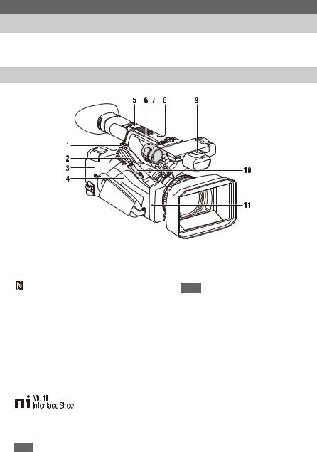
Main unit
1. Hook for shoulder strap (10)
2. ASSIGN7/DIRECT MENU button (38)
3. (N mark)
• Hold an NFC-compatible smartphone near this mark to establish a wireless connection between the camcorder and smartphone.
For details, refer to the operating instructions of the smartphone.
• NFC (Near Field Communication) is an international standard for short-range radio communication.
4. ASSIGN8/FOCUS MAG button
5. Multi Interface Shoe (rear)
For details about accessories supported by the Multi Interface Shoe, contact your sales representative.
Note
• Do not use accessories with attached screws. These may damage the multi-interface shoe.
6. Microphone clamper
7. Microphone holder (34)
Overview
Location and Function of Parts
For details about the usage and function of each part, see the referenced page.
8.GPS antenna
9.Multi Interface Shoe (front)
Note
•Do not use accessories with attached screws. These may damage the multi-interface shoe.
10.Power zoom lever (27)
11.Wi-Fi antenna
7

1.Internal microphone (33)
2.Recording/tally lamp (front) (116)
Flashes when the remaining capacity on the recording media or battery is low.
3.ASSIGN6 button
4.FULL AUTO button (26)
5.ND FILTER switch
6.ND FILTER mode switch
7.FOCUS switch (28)
8.ASSIGN3/VIDEO SIGNAL MONITOR button
9.ASSIGN1/ZEBRA button
10.ASSIGN2/PEAKING button
11.INPUT1 switch (33)
12.CH1 (INT/EXT/MI SHOE) switch (33)
13.AUDIO LEVEL (CH1) dial (33)
14.AUDIO LEVEL (CH2) dial (33)
15.CH2 (INT/EXT/MI SHOE) switch
16.INPUT2 switch (33)
17.ASSIGN5 button
18.SHUTTER switch
19.ASSIGN4 button
20.FOCUS PUSH AUTO/HOLD button (28)
21.ND control dial
22.WB SET button
23.Lens hood with lens cover (22)
8
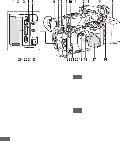
1.BATT RELEASE button (20)
2.Battery pack attachment (20)
3.Multi/Micro USB connector (76)
4.USB3.0 (HOST) connector (type A)
5.SDI OUT connector (75)
6.Diopter adjustment dial (23)
7.ON/STANDBY switch (21)
?: ON
1: STANDBY
8.Power lamp
9.USB2.0 (HOST) connector (type A)
10.IN/OUT (input/output selector) switch
11.Air outlet
Notes
•Areas around the air outlet may become hot.
•Do not cover the air outlet.
12.Handle zoom lever (27)
13.Handle record button
When the lever is set to the HOLD position, the handle record button is not operable.
14.AUDIO INPUT1 connector (33)
15.AUDIO INPUT2 connector (33)
16.Cable holder
Provided for securing a microphone cable, etc.
17.Grip belt
18.Multi selector (V/v/B/b/SET button)
19.Record button (26)
20. Air inlet
Note
• Do not cover the air inlet.
21.REMOTE connector
The REMOTE connector is used for controlling start/stop of recording and other functions on the video device and peripherals connected to it.
22.Cable clamper
Note
•Do not use for any purpose other than securing cables.
23.Wired LAN connector
24.TC IN/OUT connector
25.HDMI OUT connector (75)
26.UTILITY SD/MS slot/access lamp
Used for proxy recording and storing/loading settings (File function), and when upgrading (software update).
9
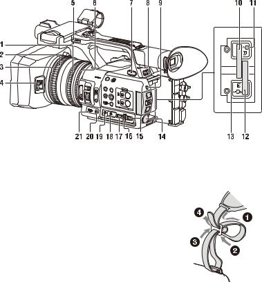
1.Zoom ring (28)
2.Focus ring (28)
3.Full MF switch (28)
Switch manual focus mode on/off by moving the focus ring forward/back.
4.Lens cover lever (22)
Opens/closes the lens cover.
5.Hook for shoulder strap
6.Iris ring (30)
7.i (headphone) jack
For stereo mini-jack headphones.
8.Recording/tally lamp (rear) (116)
Flashes when the remaining capacity on the recording media or battery is low.
9.SLOT SELECT button
10.Memory card slot A
11.Memory card A access lamp (24)
12.Memory card slot B
13.Memory card B access lamp (24)
14.DC IN connector
15.CANCEL/BACK button (81)
16.SEL/SET dial (81)
17.MENU button (81)
Button has a raised tactile bar for your convenience in locating the button.
18.WHT BAL switch (32)
19.GAIN switch (30)
20.IRIS PUSH AUTO button
21.IRIS switch (30)
To attach a shoulder strap
Attach a shoulder strap to the hooks for the shoulder strap.
10

1.THUMBNAIL button (69)
2.STOP/CAM button (70)
3.STATUS CHECK button (15)
4.PREV button (70)
5.V/v/B/b/SET button (81)
6.MENU button (81)
7.F REV button (70)
8.PLAY/PAUSE button (70)
9.F FWD button (70)
10.NEXT button (70)
11.LCD BRIGHT button (23)
12.DISPLAY button (12)
13.LCD screen (23)
14.Viewfinder (23)
15.Large eyecup
16.Air inlet
Note
• Do not cover the air inlet.
17.VOLUME buttons (29)
18.DURATION/TC/U-BIT button (36)
19.CANCEL button (81)
Bottom Side
1.Tripod screw holes (1/4 inch, 3/8 inch)
Compatible with 1/4-20UNC screws and 3/8- 16UNC screws.
Attach to a tripod (sold separately, screw length of 5.5 mm or less).
11
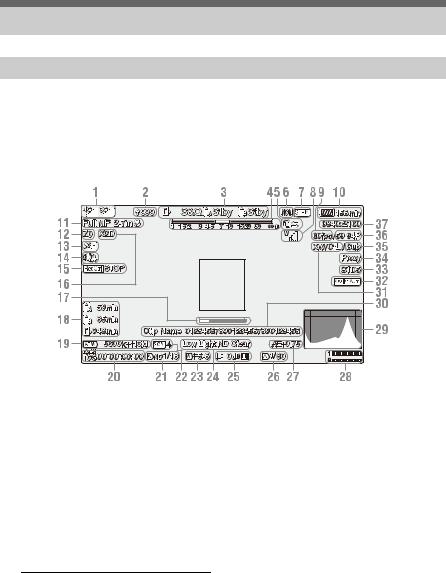
Screen Display
LCD/viewfinder screen
While recording, standing by to record, or during playback, the statuses and settings of the camcorder are superimposed on the LCD/viewfinder screen.
You can show/hide the information using the DISPLAY button. You can also select to show/hide each item independently (page 98).
Information displayed on the screen while shooting
1. Network status indicator (page 14)
Displays the status of the network connection as an icon.
The icon display varies depending on whether the NETWORK upgrade license (option) is installed or not.
2. Uploading/Number of files to transfer indicator
Displayed when the NETWORK upgrade license (option) is installed.
3. Recording mode/slot A/B operation status indicator
|
zRec |
Recording |
|
Stby |
Recording standby |
4. Depth-of-field indicator
5. Intercom indicator (page 14)
Displays the status of the intercom connection as an icon.
Displayed when the NETWORK upgrade license (option) is installed.
6.Network client mode status indicator
Displays the connection status in network client mode.
Displayed when the NETWORK upgrade license (option) is installed.
7.Streaming status indicator
Displayed when the NETWORK upgrade license (option) is installed.
8.Digital UWP unit RF level indicator
(page 15)
Displays the RF signal strength using icons when using a digitally-connected wireless audio receiver.
9.Slow & Quick Motion shooting frame rate indicator
10.Remaining battery capacity/DC IN voltage indicator
12
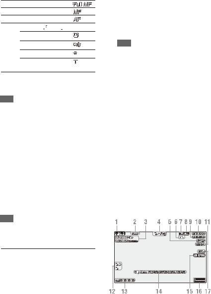
11. Focus mode indicator (page 37)
Full MF mode
MF mode
AF mode
Face detection AF (


 )
)
Face detection icon
Face only AF icon
Registered face icon
Face Only AF mode auto focus paused icon a)
a)Displayed when there is no registered face and no faces are detected, and when there is a registered face but it is not detected.
Note
• Numerical value for depth of field is a guide.
12.Zoom position indicator
Displays zoom position in the range of 0 (wide angle) to 99 (telephoto).
13.GPS status indicator
14.Image stabilization mode (SteadyShot) indicator
15.SDI output/HDMI output Rec Control indicator
Displayed when Display On/Off >SDI/HDMI Rec Control in the LCD/VF menu and SDI/ HDMI Rec Control >Setting in the Video menu are both set to On.
16.Digital extender indicator (page 115)
17.Focus assist indicator
Note
• Not displayed when using face detection AF.
18.Media remaining capacity indicator
19.White balance mode indicator
|
ATW |
Automatic mode |
|
ATW Hold |
Pause automatic mode |
|
W:P |
Preset mode |
|
W:A |
Memory A mode |
|
W:B |
Memory B mode |
20.Timecode indicator (page 36)
21.ND filter indicator (page 31)
22.Scene file indicator (page 118)
23.Iris position indicator
24.Video level warning indicator
25.Gain indicator (page 30)
26.Shutter mode/shutter speed indicator
27.AE mode/AE level indicator (page 31)
28.Audio level meter
29.VIDEO SIGNAL MONITOR display (waveform monitor/vectorscope/ histogram)
Note
•Not displayed when Output Format in the Video menu is set to 3840×2160P.
30.Clip name indicator
31.Recording format (codec) indicator
(page 113)
Displays the format that is recorded on a memory card.
32.Gamma display assist indicator (page 44)
33.Gamma indicator (page 91)
Displays the gamma setting.
34.Proxy status indicator
35.4K & HD (Sub) recording indicator
Displayed when the MPEG HD upgrade license (option) is installed.
36.System frequency and scan method indicator
37.Recording format (picture size) indicator
(page 113)
Displays the picture size that is recorded on a memory card.
Information displayed on the playback screen
The following information is superimposed on the playback picture.
1.Network status indicator
The icon display varies depending on whether the NETWORK upgrade license (option) is installed or not.
13
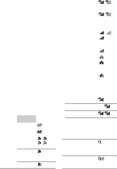
2.Uploading/Number of files to transfer indicator
Displayed when the NETWORK upgrade license (option) is installed.
3.Clip number/Total number of clips
4.Playback mode indicator
5.Playback format (frame rate) indicator
6.Intercom indicator
Displayed when the NETWORK upgrade license (option) is installed.
7.Network client mode status indicator
Displayed when the NETWORK upgrade license (option) is installed.
8.Streaming status indicator
Displayed when the NETWORK upgrade license (option) is installed.
9.Playback format (picture size) indicator
10.Remaining battery capacity/DC IN voltage indicator
11.Playback format (codec) indicator
12.Media indicator
A  mark appears to the left if the memory card is write-protected.
13.Time data indicator
The time data is displayed when Display On/Off >Timecode in the LCD/VF menu is set to On and the DISPLAY button is pressed.
14.Clip name indicator
15.Gamma display assist indicator
16.Audio level meter
17.Gamma indicator
Network connection icon indicators
|
Network |
Connection |
Icon |
||
|
mode |
status |
|||
|
Access point |
Operating as an |
|||
|
mode |
access point |
|||
|
Access point |
||||
|
operation error |
||||
|
Station mode |
Wi-Fi connected |
|||
Wi-Fi signal strength (4 levels)
Wi-Fi disconnected (incl. during setup)
Wi-Fi connection error
|
Network |
Connection |
Icon |
|
mode |
status |
|
|
Modem1) |
3G/4G signal |
3G connected |
|
strength (5 levels) |
– |
|
|
3 levels for |
||
|
modems without |
4G connected |
|
|
signal strength |
||
|
detection |
– |
|
|
Network |
||
|
connection (3G/ |
||
|
4G indeterminate) |
||
|
– |
||
|
3G/4G |
||
|
disconnected |
||
|
(incl. during |
||
|
setup) |
||
|
3G/4G |
||
|
connection error |
||
|
Wired LAN |
LAN connected |
|
|
LAN |
||
|
disconnected |
||
|
(incl. during |
||
|
setup) |
||
|
LAN connection |
||
|
error |
||
1)Two modems can be connected to the camcorder. When two modems are connected, the icons change as follows depending on the modem status.
Two modems connected, only
Modem1 in use
Two modems connected, only
Modem2 in use
Two modems connected, both in use
Intercom connection icon indicators
|
Connection status |
Icon |
|
• Network Client Mode is Off |
None |
•Network Client Mode is On and headset not connected
•Network Client Mode is On
•Headset connected
•Headset connection supported, but not connected (connection ready state)
•Network Client Mode is On
•Headset connected
•Intercom connection disabled state
14
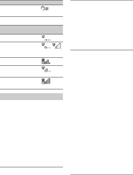
Connection status Icon
• Network Client Mode is On
• Call ready state, with headset and intercom connected
Digital UWP unit RF level icon indicators
|
Transmitter |
Reception Icon |
|
status |
status |
|
Powered off |
Not |
|
receiving |
|
|
Normal transmission |
Receiving |
|
state |
~ |
|
(4-level signal |
|
|
strength indicator) |
|
|
Muted state |
Receiving |
|
(muted) |
|
|
Remaining battery |
Receiving |
|
capacity warning |
|
|
state |
(Icon flashing) |
|
Muted / Remaining |
Receiving |
|
battery capacity |
|
|
warning state |
(Icon flashing) |
Status screen
You can check the settings and status of the camcorder on the status screen.
Status screen operations
To display the status screen:
• Push the STATUS CHECK button.
To switch the status screen:
• Turn the SEL/SET dial or press the V/v button.
To hide the status screen:
• Push the STATUS CHECK button.
Camera Status screen
Displays the picture quality, zoom settings, and status.
|
White Switch<B> |
White balance memory B |
|
adjustment value |
|
|
White Switch<A> |
White balance memory A |
|
adjustment value |
|
|
White Switch<P> |
Preset White setting |
|
ND<Preset> |
Preset1 to 3 setting for ND |
|
Filter |
|
|
Zebra1 |
Zebra1 On/Off setting and |
|
level |
|
|
Zebra2 |
Zebra2 On/Off setting and |
|
level |
|
|
Gamma |
Gamma category and curve |
|
Gain Switch |
Gain<L>, Gain<M>, |
|
Gain<H> setting |
|
|
Handle Zoom Speed |
Handle Zoom setting |
|
Scene File |
Current scene file and file ID |
Audio Status screen
Displays the input setting, audio level meter, and wind noise reduction filter setting for each channel.
|
CH1 level meter |
CH1 level meter |
|
CH1 Input Source |
CH1 input source |
|
CH1 Ref./Sens. |
CH1 input reference level |
|
CH1 Wind Filter |
CH1 microphone wind |
|
reduction filter setting |
|
|
CH2 level meter |
CH2 level meter |
|
CH2 Input Source |
CH2 input source |
|
CH2 Ref./Sens. |
CH2 input reference level |
|
CH2 Wind Filter |
CH2 microphone wind |
|
reduction filter setting |
|
|
CH3 level meter |
CH3 level meter |
|
CH3 Input Source |
CH3 input source |
|
CH3 Ref./Sens. |
CH3 input reference level |
|
CH3 Wind Filter |
CH3 microphone wind |
|
reduction filter setting |
|
|
CH4 level meter |
CH4 level meter |
|
CH4 Input Source |
CH4 input source |
|
CH4 Ref./Sens. |
CH4 input reference level |
|
CH4 Wind Filter |
CH4 microphone wind |
|
reduction filter setting |
|
|
HDMI Output CH |
HDMI output audio channel |
|
combination setting |
|
|
Analog Output CH |
Analog output audio channel |
|
combination setting |
|
|
Monitor CH |
Monitor channel setting |
|
Headphone Out |
Headphone output type |
|
setting |
|
System Status screen
Displays the video signal settings.
|
Frequency/Scan |
System frequency and |
|
scanning method settings |
|
|
File System |
File system setting |
|
Displayed when the MPEG |
|
|
HD upgrade license (option) |
|
|
is installed. |
|
|
Codec |
Codec setting |
15

|
Simul Rec |
2-slot Simul Rec On/Off |
|
status |
|
|
Title Prefix |
Clip name title prefix |
|
Picture Size |
Recording format picture size |
|
Rec Function |
Enabled special recording |
|
format and settings |
|
|
Clip Continuous Rec |
Clip Continuous Rec On/Off |
|
status |
|
|
Picture Cache Rec |
Picture Cache Rec On/Off |
|
status and setting |
|
|
Number |
Clip name numeric suffix |
|
Shooting Mode |
Shooting mode setting |
|
4K & HD (Sub) Rec |
4K & HD (Sub) recording |
|
function On/Off status |
|
|
Displayed when the MPEG |
|
|
HD upgrade license (option) |
|
|
is installed. |
|
|
Proxy Rec |
Proxy recording On/Off |
|
status and setting |
|
Video Output Status screen
Displays the SDI and HDMI output settings.
|
SDI |
Output picture size |
|
Rec Control status |
|
|
Output On/Off |
|
|
HDMI |
Output picture size |
|
Rec Control status |
|
|
Output On/Off |
|
|
Gamma |
Gamma setting |
|
Color Gamut |
Color gamut setting |
|
Gamma Display Assist |
Gamma display assist setting |
Assignable Button Status screen
Displays the functions assigned to each of the assignable buttons.
|
1 |
Function assigned to the |
|
Assign 1 button |
|
|
2 |
Function assigned to the |
|
Assign 2 button |
|
|
3 |
Function assigned to the |
|
Assign 3 button |
|
|
4 |
Function assigned to the |
|
Assign 4 button |
|
|
5 |
Function assigned to the |
|
Assign 5 button |
|
|
6 |
Function assigned to the |
|
Assign 6 button |
|
|
7 |
Function assigned to the |
|
Assign 7 button |
|
|
8 |
Function assigned to the |
|
Assign 8 button |
|
Battery Status screen
Displays information about the battery and DC IN source.
|
Detected Battery |
Battery type |
|
Remaining |
Remaining capacity (%) |
|
Charge Count |
Number of recharges |
|
Capacity |
Remaining capacity (Ah) |
|
Voltage |
Voltage (V) |
|
Manufacture Date |
Date of battery manufacture |
|
Video Light Remaining |
Remaining charge level of the |
|
video light battery |
|
|
Power Source |
Power supply source |
|
Supplied Voltage |
Supplied power source |
|
voltage |
|
Media Status screen
Displays the remaining space, available recording time, and estimated service life of the recording media (memory card A/memory card B) and UTILITY media.
|
Media A information |
Displays the media icon |
|
when recording media is |
|
|
inserted in slot A. |
|
|
Media A protection |
Displays the lock icon when |
|
the recording media inserted |
|
|
in slot A is protected |
|
|
(locked). |
|
|
Media A remaining |
Displays the remaining |
|
capacity meter |
capacity of recording media |
|
inserted in slot A expressed |
|
|
as a percentage on a bar |
|
|
graph. |
|
|
Media A remaining |
Displays an estimate of the |
|
recording time |
remaining recording time of |
|
the recording media inserted |
|
|
in slot A in units of minutes |
|
|
under the current recording |
|
|
conditions. |
|
|
Media B information |
Displays the media icon |
|
when recording media is |
|
|
inserted in slot B. |
|
|
Media B protection |
Displays the lock icon when |
|
the recording media inserted |
|
|
in slot B is protected |
|
|
(locked). |
|
|
Media B remaining |
Displays the remaining |
|
capacity meter |
capacity of recording media |
|
inserted in slot B expressed |
|
|
as a percentage on a bar |
|
|
graph. |
|
16

|
Media B remaining |
Displays an estimate of the |
|
recording time |
remaining recording time of |
|
the recording media inserted |
|
|
in slot B in units of minutes |
|
|
under the current recording |
|
|
conditions. |
|
|
UTILITY media |
Displays the media icon |
|
information |
when media is inserted in the |
|
UTILITY SD/MS slot. |
|
|
UTILITY media |
Displays the lock icon when |
|
protection |
the media inserted in the |
|
UTILITY SD/MS slot is |
|
|
protected (locked). |
|
|
UTILITY media |
Displays the remaining |
|
remaining capacity |
capacity of media inserted in |
|
meter |
the UTILITY SD/MS slot |
|
expressed as a percentage on |
|
|
a bar graph. |
|
|
UTILITY media |
Displays an estimate of the |
|
remaining capacity |
remaining recording time of |
|
the recording media inserted |
|
|
in the UTILITY SD/MS slot |
|
|
in units of minutes. Or |
|
|
displays the remaining |
|
|
capacity in units of GB. |
|
Rec Button Settings Status screen
Displays the setting status of the record button and handle record button.
|
Rec Button |
Displays the recording target |
|
slot of the record button |
|
|
Handle Rec Button |
Displays the recording target |
|
slot of the handle record |
|
|
button |
|
GPS Status screen
Displays the GPS positioning status and information.
|
GPS |
GPS signal positioning status |
|
Dilution of Precision |
Position information |
|
precision |
|
|
Latitude |
Latitude information |
|
Longitude |
Longitude information |
|
Altitude |
Altitude information |
|
Positioning date and |
Positioning date and time |
|
time |
|
|
Current date and time |
Current date and time |
|
Time Zone |
Time zone setting |
Network Status screen
Displays the connection status of the network connection.
Wired LAN, Modem1, and Modem2 are displayed when the NETWORK upgrade license (option) is installed.
|
Wireless LAN |
Wireless network settings, |
|
connection status |
|
|
Wired LAN |
Wired LAN network settings, |
|
connection status |
|
|
Modem1 |
Wireless network settings, |
|
connection status using |
|
|
modem (sold separately) |
|
|
Modem2 |
Wireless network settings, |
|
connection status using |
|
|
modem (sold separately) |
|
Wireless LAN settings
|
Setting |
Status |
Description |
|
display |
display |
|
|
Off |
— |
Wireless LAN |
|
setting is off. |
||
|
Access Point |
Non Active |
Not operating as an |
|
Mode |
access point. |
|
|
Displayed when |
||
|
Wi-Fi chip fails. |
||
|
Active |
Operating as an |
|
|
access point. |
||
|
Station Mode |
Non Active |
Not operating in |
|
station mode. |
||
|
Displayed when |
||
|
Wi-Fi chip fails. |
||
|
Searching |
Attempting to |
|
|
connect to the |
||
|
previously |
||
|
connected network |
||
|
(access point). |
||
|
Disconnected |
Not connected to a |
|
|
network (access |
||
|
point). |
||
|
Also displayed |
||
|
when IP address |
||
|
was not assigned |
||
|
using DHCP. |
||
|
<SSID> |
Connected to |
|
|
<SSID> network |
||
|
(access point). |
||
17

Wired LAN settings
|
Setting |
Status |
Description |
|
display |
display |
|
|
Off |
— |
Wired LAN setting |
|
is off. |
||
|
On |
Disconnected |
Disconnected from |
|
network. |
||
|
Also displayed |
||
|
when IP address |
||
|
was not assigned |
||
|
using DHCP. |
||
|
Connected |
Connected to a |
|
|
network. |
||
Modem1 and Modem2 settings
|
Setting |
Status |
Description |
|
display |
display |
|
|
Off |
— |
Modem setting is |
|
off. |
||
|
On |
Disconnected |
Not connected to a |
|
network. |
||
|
Connected |
Connected to a |
|
|
network. |
||
|
Connecting |
Attempting to |
|
|
connect to a |
||
|
network. |
||
|
No Modem |
Modem dongle is |
|
|
not inserted. |
||
NCM/Streaming Status screen
Displays the connection status and streaming status in network client mode. Displayed when the NETWORK upgrade license (option) is installed.
|
Network Client Mode |
Network client mode status |
|
Status |
|
|
CCM Name |
Name of connected CCM in |
|
network client mode |
|
|
CCM Address |
Address of connected CCM |
|
in network client mode |
|
|
QoS Streaming1 Bit |
Streaming bit rate 1 |
|
Rate |
|
|
QoS Streaming2 Bit |
Streaming bit rate 2 |
|
Rate |
|
|
Streaming Status |
Streaming status |
|
Streaming Format |
Streaming format |
|
information |
|
|
Streaming Type |
Type of currently selected |
|
streaming setting |
|
|
Streaming Destination |
Streaming destination |
|
Address |
address |
|
Streaming Audio |
Audio channel to |
|
Channel |
superimpose on streaming |
|
output |
|
Network Client Mode Status settings
Displayed when the NETWORK upgrade license (option) is installed.
|
Status display |
Description |
|
|
Off |
Network client mode is off. |
|
|
Connected |
Network client mode is on, |
|
|
CCM/XDCAM air is |
||
|
connected, and control from |
||
|
CCM/XDCAM air is |
||
|
enabled. |
||
|
Connecting |
Attempting to connect to |
|
|
CCM/XDCAM air. |
||
|
Note |
||
|
• If the status does not change |
||
|
from “Connecting,” the |
||
|
CCM address setting may |
||
|
be incorrect. Check that the |
||
|
address is set correctly. |
||
|
Destination Address |
The host name or IP address |
|
|
Error |
of the CCM to connect may |
|
|
be incorrect. |
||
|
Authentication Failed |
The user name or password |
|
|
used to connect to the CCM |
||
|
may be incorrect. |
||
|
No Network Access |
Cannot connect to a network. |
|
|
Check the network |
||
|
connection status and |
||
|
settings. |
||
|
Certificate is not yet |
The CCM certificate is not |
|
|
Valid |
valid. |
|
|
The network date and time |
||
|
settings may be incorrect. |
||
|
Certificate has Expired |
The period of validity of the |
|
|
CCM certificate has expired. |
||
|
The network date and time |
||
|
settings may be incorrect. |
||
|
Root Certificate Error |
The root certificate is invalid. |
|
|
Note |
||
|
• If this error message is |
||
|
displayed, contact your |
||
|
Sony service representative. |
Intermediate Cert. Error An intermediate certificate is invalid.
Note
•If this error message is displayed, contact your Sony service representative.
18

|
Status display |
Description |
Server Certificate Error The server certificate is invalid.
Note
•If this error message is displayed, contact your Sony service representative.
Streaming Status settings
Displayed when the NETWORK upgrade license (option) is installed.
|
Status display |
Description |
|
Off |
Streaming is off. |
|
Distributing |
Streaming is in progress. |
|
Preparing |
Preparing for streaming. |
|
Destination Address |
The host name or IP address |
|
Error |
of the streaming destination |
|
may be incorrect. |
|
|
No Network Access |
Cannot connect to a network. |
|
Check the network |
|
|
connection status and |
|
|
settings. |
|
File Transfer Status screen
Displays file transfer information. Displayed when the NETWORK upgrade license (option) is installed.
|
Auto Upload (Proxy) |
Auto Upload (Proxy) On/Off |
|
status |
|
|
Job Status(Remain/ |
Number of remaining jobs |
|
Total) |
and total number of jobs |
|
Total Transfer Progress |
Transfer progress of total jobs |
|
Default Upload Server |
Name of the destination |
|
server for auto upload of |
|
|
proxy files and upload of files |
|
|
from the thumbnail screen |
|
|
Current File Transfer |
Transfer progress of file |
|
Progress |
currently being uploaded. |
|
Current Transferring |
Name of file currently being |
|
File Name |
uploaded. |
|
Server Address |
Address of file transfer server |
|
Destination Directory |
Destination directory of file |
|
transfer server |
|
19
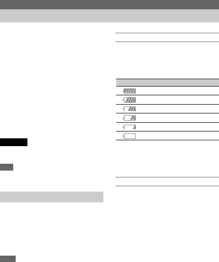
Preparation
Power Supply
You can use a battery pack or AC power supply from an AC adapter.
When an AC adapter is connected, the AC adapter has priority even when a battery pack is attached.
For safety, use only the Sony battery packs and AC adaptors listed below.
Lithium-ion battery packs
BP-U30 (supplied)
BP-U60
BP-U60T
BP-U90
AC adapters/chargers
BC-U1A (supplied)
BC-U2A
WARNING
Do not store battery packs in locations exposed to direct sunlight, flame, or high temperature.
Note
•When operating from a power outlet, use the supplied AC adapter.
Using a battery pack
To attach a battery pack, plug the battery pack into the attachment (page 9) as far as it will go, and then slide it down to lock it into position.
To remove a battery pack, press and hold the BATT RELEASE button (page 9), slide the battery pack up and then pull it out of the attachment.
Notes
•Before use, charge the battery pack with the BC-U1A (supplied) or BC-U2A Charger.
•Charging a battery immediately after use while it is still warm may not fully recharge the battery.
•The high-capacity BP-U90 Battery Pack is large, and protrudes from the camcorder when attached. The BPU90 is convenient when using the camcorder attached to a tripod for extended recording periods.
Checking the remaining capacity
When recording or playback is in progress on the battery pack, an icon to show the current battery charge level and usage time remaining are displayed on the LCD/viewfinder screen
(page 12).
|
Icon |
Remaining capacity |
|
100% to 91% |
|
|
90% to 71% |
|
|
70% to 51% |
|
|
50% to 31% |
|
|
30% to 11% |
|
|
10% to 0% |
The camcorder indicates the remaining usage time in minutes by calculating the available time with the battery pack if operation is continued at the current rate of power consumption.
If the battery pack charge becomes low
If the remaining battery charge falls below a certain level during operation (Low Battery state), a low-battery message appears, the recording/tally lamp starts flashing, and a beep sound will warn you.
If the remaining battery charge falls below the level at which operation cannot continue (Battery Empty state), a battery-empty message appears. Replace with a charged battery pack.
Changing the warning levels
The Low Battery level is set to 10% of full battery charge and the Battery Empty level is set to 3% by factory default. You can change the warning level settings using Battery Alarm (page 116) in the System menu.
20
![]()
|
Using AC power |
Turning the camcorder on/off |
|
Connecting the camcorder to a power outlet |
To turn the camcorder on, set the ON/STANDBY |
|
allows use without worrying about the need to |
switch (page 9) to the ON position ([). To turn the |
|
recharge the battery pack. |
camcorder off, set the ON/STANDBY switch to |
|
the STANDBY position (1). |
|
|
Notes |
|
|
• Even when the ON/STANDBY switch is set to the |
|
|
STANDBY position, the unit continues to draw |
|
|
standby electric power. Remove the battery pack if not |
|
|
using your camcorder for an extended period. |
|
|
• Remove the battery or disconnect the DC IN power |
|
|
supply after the power lamp is extinguished when the |
|
|
power switch is set to the STANDBY position. If |
|
|
power is removed while the switch is in the ON |
|
|
position, a malfunction of the camcorder or memory |
|
|
cards may occur. |
|
DC IN |
AC adapter plug |
|
connector |
1Connect the power cord (mains lead) to the AC Adapter.
2Connect the AC Adapter to the DC IN connector of the camcorder.
3Connect the power cord (mains lead) to the wall outlet (wall socket).
AC adapters
•Do not connect and use an AC adapter in a confined space, such as between a wall and furniture.
•If a problem occurs during operation, immediately disconnect the power cord from the outlet.
•Do not short-circuit the plug of the AC adapter with any metallic objects. Doing so will cause a malfunction.
•You cannot charge the camcorder by connecting it to the AC Adapter.
21
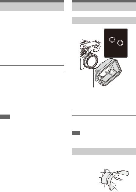
Setting the Clock
When you turn the camcorder on for the first time after purchasing or the backup battery has completely discharged, the initial setting display appears on the viewfinder screen and LCD screen.
Set the date and time of the internal clock using this screen.
Time Zone
The value shows the time difference from UTC (Coordinated Universal Time). Change the setting as required.
Setting the date and time
Move the cursor using the V/v/B/b button (page 9) or SEL/SET dial (page 10), and press the SET button or SEL/SET dial to set each item. Finally, move the cursor to [Finish] and press the SET button or SEL/SET dial to close the settings screen and finish setting the clock.
Once the settings screen is closed, you can change the date, time, and time zone settings using Clock Set (page 116) in the System menu.
Notes
•If the clock setting is lost because the backup battery becomes fully discharged due to power being disconnected for an extended period (no battery pack and no DC IN power source), the initial settings screen will be displayed when you next turn the camcorder on.
•While the initial settings screen is displayed, no other operation, except turning the power off, is permitted until you finish the settings on this screen.
•If you do not use your camcorder for about 3 months, the built-in rechargeable battery gets discharged and the date and time settings may be cleared from the memory. In that case, charge the rechargeable battery and then set the date and time again (page 123).
Attaching Devices
Attaching the lens hood
PUSH (lens hood release) button
Align the marks on the lens hood to those on the camcorder, and turn the lens hood in the direction of the arrow 2 until it is locked.
Removing the lens hood
Turn the lens hood in the opposite direction of the arrow in the illustration while pressing the PUSH (lens hood release) button.
Note
•Remove the lens hood when you attach/detach an ø82 mm polarizing filter or protective filter.
Attaching the large eyecup
Stretch the large eyecup slightly and fit it over the groove on the viewfinder.
Large eyecup (supplied)
22
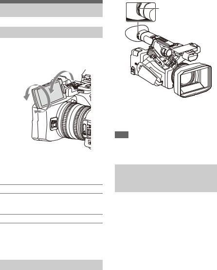
Adjusting the Screens
Adjusting the LCD screen
Open the LCD screen 180 degrees (1), then rotate it to the best angle to record or play back (2).
1 Open 180 degrees
2 90 degrees (max.)
2 180 degrees (max.)
You can adjust the angle so that the viewfinder is facing the subject. Images are displayed as mirror images on the LCD screen, but are recorded as normal images.
Adjusting the backlight
Switch the brightness of the backlight using the LCD BRIGHT button (page 11).
Adjusting the brightness
Adjust the brightness using LCD Setting >Brightness (page 96) in the LCD/VF menu. Changes in the brightness do not affect the brightness of recorded images.
Adjusting the viewfinder
Look through the viewfinder with the LCD screen closed when using the viewfinder.
If the viewfinder screen display is not clear, adjust it using the diopter adjustment dial below the viewfinder.
Diopter adjustment dial Move it until the picture becomes clear.
Adjusting the brightness
Adjust the brightness using VF Setting >Brightness (page 96) in the LCD/VF menu.
Note
•When you move your eyes away from the viewfinder, the screen colors may be temporarily inverted to prevent screen burn-in, but this is not a malfunction.
Adjusting the brightness of the LCD/viewfinder screen using an assignable button
You can display a level bar for adjusting the brightness of the LCD screen/viewfinder screen by assigning LCD/VF Adjust to an assignable button (page 38) beforehand and then pressing that button.
1 Press the button assigned with LCD/VF Adjust to display a level bar for adjusting the brightness.
Each time the button is pressed, the display switches in sequence between level bar for the LCD screen t level bar for the viewfinder t no display.
2 Adjust the level using the V/v/B/b button or SEL/SET dial, and press the SET button or SEL/SET dial.
The level bar disappears.
Press the button assigned with LCD/VF Adjust or do not perform any operation for 3 seconds to hide the level bar.
23

Using Memory Cards
This camcorder records audio and video on memory cards (sold separately) inserted in the memory card slots.
About memory cards
Supported memory cards
The following memory cards are supported.
For details about recording media and compatible formats, see page 127.
SDXC memory cards (Class 10)
•A memory card removed from the camcorder after recording ended may be hot. This is not a malfunction.
Switching between memory cards
When memory cards are loaded in both card slots A and B, you can switch the card used for recording by pressing the SLOT SELECT button
(page 10).
If a card becomes full during recording, the camcorder automatically switches to the other card.
Note
•The SLOT SELECT button is disabled during playback. The memory cards are not switched even if you press the button. The button is enabled while the thumbnail screen (page 69) is displayed.
Inserting memory cards
1 Open the cover of the card slot block.
2 Insert the memory card with the label facing to the right.
The access lamp (page 10) lights in red, then changes to green once the memory card is ready for use.
3 Close the cover.
Note
•The memory card, memory card slot, and image data on the memory card may be damaged if the card is forced into the slot in the incorrect orientation.
Removing a memory card
1 Open the cover of the card slot block, and lightly press the memory card in.
The memory card pops out. During recording, this will stop the recording.
2 Remove the memory card.
Notes
•If the camcorder is turned off or the memory card is removed while the memory card is being accessed, the integrity of data on the card cannot be guaranteed. All data recorded on the card may be discarded. Always make sure the access indicator is green or off before turning off the camcorder or removing the memory card.
Formatting (initializing) a memory card
Memory cards must be formatted the first time they are used in the camcorder.
Memory cards for use in the camcorder should be formatted using the format function of the camcorder.
If a message appears when the memory card is inserted into the camcorder, format the memory card.
If a memory card that was formatted in a format unsupported by this camcorder is inserted, the message “Unsupported File System” is displayed on the LCD/viewfinder screen.
Format the media as described below.
To execute formatting
Using Format Media (page 104) in the Media menu, specify Media(A) (slot A) or Media(B) (slot B), then select Execute.
A message is displayed while formatting is in progress, and the access indicator is lit red. When formatting ends, a completion message appears.
Note
•Formatting a memory card erases all data on the card, including protected video. The data cannot be restored.
To use media formatted on the camcorder in the slot of another device
Make a backup of the media, then format it using the other device.
24

Checking the remaining recording time
While recording (or standing by to record), you can check the remaining space for the memory cards loaded in the card slots on the A/B slot media status/remaining space display of the LCD/ viewfinder screen (page 12).
The remaining recording time is calculated from the remaining capacity of the media in each slot and the current video format (recording bit rate), and is displayed in units of minutes.
Note
•A  icon appears if the memory card is writeprotected.
Replacing a memory card
•If the available time on two cards in total becomes less than 5 minutes, the warning message “Media Near Full” is displayed, the recording/tally lamp flashes, and a beep sound is output to the headphones to warn you. Replace with media that has free space.
•If you continue recording until the total remaining time reaches zero, the message changes to “Media Full,” and recording stops.
Note
•Up to approximately 600 clips can be recorded on one memory card.
If the number of recorded clips reaches the limit, an indication that the maximum number of clips has been reached is displayed.
Restoring a memory card
If for any reason an error should occur in a memory card, the card must be restored before use.
When you load a memory card that needs to be restored, a message appears on the LCD/ viewfinder screen to ask whether you want to restore it.
Restoring a card
Select Execute using the V/v/B/b button or
SEL/SET dial, and press the SET button or SEL/SET dial.
A message and progress status (%) are displayed while formatting is in progress, and the access lamp is lit red.
When restoration ends, a completion message appears.
If restoration fails
•Write protected memory cards and cards on which memory errors have occurred cannot be restored. A warning message appears for such cards. Follow the instructions in the message and unprotect the card or replace it with another card.
•Memory cards on which memory errors have occurred may become usable if they are reformatted.
•In some cases, some clips can be restored while others cannot. The restored clips can be played normally.
•If the message “Could not Restore Some Clips” keeps appearing after repeated attempts at restoration, it may be possible to restore the memory card with the following procedure.
1Use the copy function (page 73) of the camcorder to copy the required clips to another memory card.
2Format the unusable memory card on the camcorder.
3Copy the required clips back to the newly formatted memory card.
Notes
•For restoration of media recorded with this camcorder, be sure to use this camcorder.
Media recorded with a device other than this camcorder or with another camcorder of different version (even of the same model) may not be restored using this camcorder.
•Clips with duration of less than 1 minute may not be restorable.
•In 4K & HD (Sub) recording mode, only the 4K (QFHD) main clip is the target for restoration.
25

Shooting
Basic Operation Procedure
Shooting
Basic shooting is conducted using the following procedure.
1 Attach the necessary devices, and check that power is being supplied.
2 Load the memory card(s).
If you load two memory cards in memory card slots A and B, recording is continued by automatically switching to the second card when the first card becomes full.
3 Set the ON/STANDBY switch to the ON position.
The recording screen is displayed on the LCD/viewfinder screen.
4 Press the grip or handle record button
(page 9).
The recording/tally lamp lights and recording begins.
5 To stop recording, press the record button again.
Recording stops, and the camcorder switches to STBY (standby) mode.
Shooting (Full Auto Mode)
Press the FULL AUTO button, turning the button indicator on.
Full Auto mode is turned on, Auto Exposure (page 87) is activated, and Auto ND Filter, Auto Iris, AGC (Auto Gain Control), Auto Shutter, and ATW (Auto Tracing White balance) are set to On. Then, the brightness and white balance are automatically adjusted.
When you wish to adjust them manually, turn Full Auto mode off.
Continuous recording on the memory cards (Relay Rec)
When memory cards are inserted in both slots A and B, recording automatically switches to the second memory card just before the remaining capacity on the first card is reduced to zero. You can continue recording continuously when switching memory cards by replacing the memory card that is full with a new memory card.
Notes
•Do not eject a memory card while recording to it is in progress. Remove only the memory card in the slot whose access lamp is turned off during recording.
•If a recordable memory card is loaded into the other slot when the remaining time of the memory card that is recording is less than 1 minute, the message “Will Switch Slots Soon” is displayed. The message disappears after switching memory card slots.
•The relay recording function may not work if you start recording when the remaining time of the memory card is less than 1 minute. To perform the relay recording properly, make sure that the remaining time of the memory card is more than 1 minute.
•Video created using the camcorder relay recording function cannot be played back seamlessly on the camcorder.
•To combine video created using the camcorder relay recording function, use Content Browser software. Check the operating environment for Content Browser before use.
•Use the same type of SD cards for relay recording using SD cards.
26
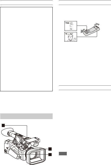
About clips
Clip (recording data)
When you stop recording, video, audio, and subsidiary data from the start to end of the recording are recorded as a single clip on a memory card.
Clip names
Each clip recorded by the camcorder is automatically assigned a name using the naming mode that is set in Clip Naming (page 105) of the Media menu.
Maximum clip duration
The maximum duration of a clip varies depending on the recording format. The maximum duration of continuous
recording is the same as the maximum duration of a clip. If the recording time exceeds the maximum duration of a clip, a new clip is created automatically and recording continues. The new clip appears as a separate clip on the thumbnail screen.
For details about the maximum recording time of a clip for each recording format, see
“Maximum recording time for a clip” (page 128).
To delete a clip
You can delete the last recorded clip using the Last Clip Delete function (page 115). To delete all clips or specific clips, perform the operation from the thumbnail screen (page 74).
Adjusting the zoom
Using the power zoom lever
Zoom by pressing the power zoom lever C. Lightly press the power zoom lever Cfor a slower zoom. Fully press it for a faster zoom.
Wide view: Wide
Close view: Telephoto
•The minimum distance required between your camcorder and the subject for focus is about 1 cm (about 13/32 in.) for wide angle and about 80 cm (about 2 5/8 feet) for telephoto.
•The focus may not be adjusted at certain zoom positions if the subject is within 80 cm (about 2 5/8 feet) from your camcorder.
•Keep your finger on the power zoom lever C.
If you move your finger off the power zoom lever C, the operation sound of the power
zoom lever may also be recorded.
Using the handle zoom
1.Set the handle zoom operation to “Low,” “High,” or “Variable” using Handle Zoom (page 88) >Setting in the Camera menu.
•When set to “Variable,” you can zoom in or out at a variable speed according to the pressure applied to the switch.
•When set to “Low” or “High”, you can zoom in or out at fixed speed, regardless of the pressure applied to the switch. You can set the speed to “Low” or “High” using Handle Zoom in the Camera menu.
•By assigning the Handle Zoom >Setting function to an assignable button (page 38), you can switch the handle zoom operation each time the button is pressed.
2.Press the handle zoom lever Ato zoom in or out.
Notes
•You cannot use the handle zoom lever Awhen the handle zoom operation is set to OFF.
•Uneven zooming may occur when the zoom speed is set to a low value.
27
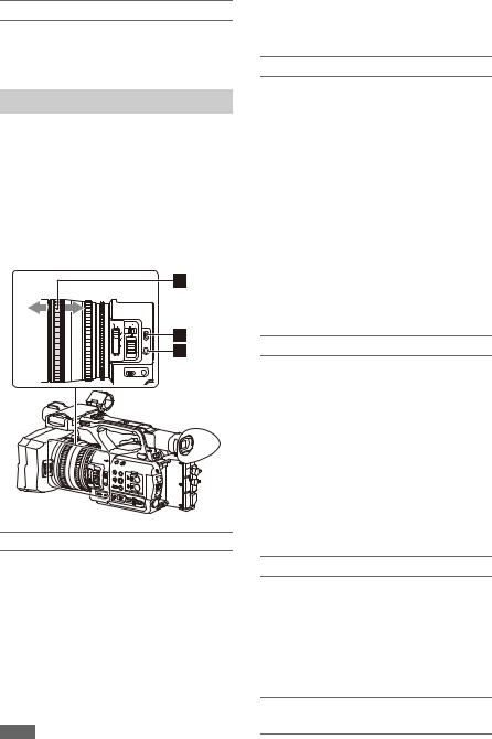
Using the zoom ring
Zoom by turning the zoom ring B.
You can zoom at the desired speed by turning the zoom ring B. Fine adjustment is also possible.
Adjusting the focus
Tips for focusing
•Move the power zoom lever towards T (telephoto) and adjust the focus, then, towards W (wide angle) to adjust the zoom for recording.
•When you want to record a close-up image of a subject, move the power zoom lever towards W (wide angle) to fully magnify the image, then adjust the focus.
Adjusting in Full MF mode
Pull the focus ring Atoward the back (toward the camcorder) to activate Full MF mode for full manual focus control.
Turn the focus ring to adjust the focus while monitoring the image on the LCD/viewfinder screen.
In Full MF mode, you can use the distance markers printed on the focus ring as a guide when adjusting the focus. The distances where the picture is in focus correspond to the positions of the distance markers.
Notes
•Do not use excessive force at both ends of the travel when turning the focus ring.
•While in Full MF mode, the auto focus and push auto focus functions do not work.
•Macro is set to off regardless of the Focus Macro setting in the Camera menu.
Adjusting in MF mode
In MF (manual focus) mode, you can also use auto focus operation whenever required.
Slide the focus ring Atoward the front (toward the lens hood) and set the FOCUS switch Bto MANUAL.
Using automatic focus temporarily (Push auto focus)
In MF mode, auto focus is activated while the FOCUS PUSH AUTO/HOLD button Cof the lens is pressed or while an assignable button (page 38) assigned with Push AF/Push MF is pressed.
The focus returns to manual focus when you release the button.
This function is useful for shifting the focus from one subject to another during manual focus mode.
Adjusting in AF mode
In AF (auto focus) mode, the focus is adjusted automatically.
Slide the focus ring Atoward the front and set the FOCUS switch Bto AUTO.
Using manual focus temporarily (Push manual focus)
In AF mode, manual focus is activated while the FOCUS PUSH AUTO/HOLD button of the lens is pressed or while an assignable button (page 38) assigned with Push AF/Push MF is pressed.
The focus returns to auto focus when you release the button.
Using macro mode
In MF mode or AF mode, set Focus (page 86) >Focus Macro in the Camera menu to On or press an assignable button assigned with Focus Macro (page 38) to activate macro mode to enable focusing over a range that includes the macro area.
Macro mode is disabled in Full MF mode.
Focusing using magnified view (Focus Magnifier)
When an assignable button (page 38) assigned with Focus Magnifier is pressed, the focus
28

magnifier screen appears showing the part of the image magnified.
The magnification switches between 4× and 8× each time the button is pressed when the recording format is QFHD. You can move the magnified position using the V/v/B/b button. The center of the screen is magnified at a fixed 2× in recording formats other than QFHD.
Press the button again to return to the normal screen.
This function is useful for checking the focus.
Note
•Even though the image appears magnified on the screen, the recorded image is not magnified.
Monitoring audio while shooting
Connecting a set of headphones to the headphone jack (stereo mini jack) (page 10) enables you to monitor the audio being recorded.
Note
•The built-in speaker is disabled while shooting (recording or recording standby).
To adjust the audio monitoring volume
Use the VOLUME buttons (page 11).
To change the audio monitoring channel
Select the channel using Audio Output (page 95) in the Audio menu.
Changing Basic Settings
You can change the settings based on the video application or recording conditions.
Video format
The formats available for selection vary depending on the exFAT/FAT file system, system frequency, and codec settings.
Switching the exFAT/FAT file system
Switch using Rec Format (page 113) >File System in the System menu.
The camcorder automatically restarts after switching.
File System can be configured when the MPEG HD upgrade license (option) is installed.
Note
•You cannot switch between exFAT/FAT during recording or playback.
Switching the system frequency
Switch using Rec Format (page 113) >Frequency in the System menu.
The camcorder automatically restarts after switching.
Note
•You cannot switch the system frequency during recording or playback.
Switching the codec
Switch using Rec Format (page 113) >Codec in the System menu.
Note
•You cannot switch the codec during recording or playback.
Changing the format
Switch using Rec Format (page 113) >Video Format in the System menu.
The signals from the SDI OUT and HDMI OUT connectors are also output in the format selected using this menu.
29
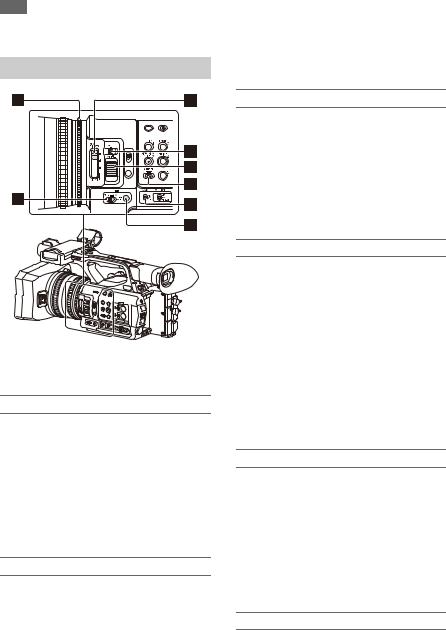
Note
•You cannot change the format during recording or playback.
Adjusting the brightness
You can adjust the brightness by adjusting the iris, gain, shutter speed, and by adjusting the light level using ND filters.
Shooting using auto iris
When Full Auto mode (page 26) is on
The iris is forcibly set to Auto mode.
When Full Auto mode is off
Set the IRIS switch Bto AUTO. Auto mode is set.
The adjustment setting applied when the iris AUTO/MANUAL switch is set to MANUAL can also be configured using the direct menu
(page 36).
Shooting using manual iris
When Full Auto mode is off, set the IRIS switch Bto MANUAL. Manual mode is set. Turn the iris ring Ato adjust the iris.
The adjustment setting applied when the iris AUTO/MANUAL switch is set to MANUAL can also be configured using the direct menu
(page 36).
Switching to auto iris temporarily
In manual iris mode, press the IRIS PUSH AUTO button Hto activate the one-push auto iris function.
Auto iris is active while the button is pressed. Release the button to return to manual iris mode.
Shooting with auto gain (AGC)
When Full Auto mode (page 26) is on
AGC (Auto Gain Control) mode is forcibly enabled.
When Full Auto mode is off
Set Auto Exposure >AGC (page 87) in the Camera menu to On to activate AGC mode. You can also set AGC on/off in the direct menu
(page 36).
Shooting with fixed gain
1.Set Full Auto mode off.
2.When the gain is automatically adjusted, set Auto Exposure >AGC (page 87) in the Camera menu to Off.
“AGC” disappears.
3.Set the GAIN switch Gto H, M, or L. The gain value set for the selected gain switch position appears on the screen.
You can set the gain value for H/M/L using Gain (page 86) in the Camera menu.
You can also set the H/M/L value in the direct menu (page 36).
Shooting in auto shutter mode
When Full Auto mode (page 26) is on
The shutter is forcibly set to auto shutter.
When Full Auto mode is off
Set Auto Exposure >Auto Shutter (page 88) in the Camera menu to On to activate auto shutter speed mode.
Auto shutter can also be activated by selecting Auto Shutter in the direct menu and setting it to on.
Shooting with a fixed shutter
When Full Auto mode is off and Auto Exposure >Auto Shutter (page 88) in the Camera menu is set to Off, set the SHUTTER switch Fto the ON position to set fixed shutter with the shutter mode
30
![]()
and speed configured using Shutter (page 87) in the Camera menu.
When the SHUTTER switch is set to the OFF position, the shutter speed matches the recording frame rate.
Setting in the Camera menu
Select Shutter (page 87) in the Camera menu and set the shutter mode and speed.
Setting using the direct menu
You can also set ECS mode (page 87) on/off and the shutter speed in the direct menu (page 36).
Adjusting the light level (ND filter)
You can shoot a subject with the proper brightness by using the ND FILTER switch C when the recording environment is too bright. The camcorder features two ND filter modes. You can switch the mode using the ND FILTER mode switch D.
Preset mode
Set the ND FILTER mode switch Dto PRESET, then set the ND FILTER switch Cto the following.
CLEAR: ND filter is not used.
1:Filter density set using ND Filter >Preset1 in the Camera menu. The default setting is 1/4.
2:Filter density set using ND Filter >Preset2 in the Camera menu. The default setting is 1/16.
3:Filter density set using ND Filter >Preset3 in the Camera menu. The default setting is 1/64.
Variable mode
Set the ND FILTER mode switch Dto PRESET, then set the ND FILTER switch Cto the following.
CLEAR: ND filter is not used.
1, 2, 3: You can set the filter density in a continuous range from 1/4 to 1/128 using the ND control dial E.
The ND FILTER switch Bposition (1/2/3) does not affect the filter density adjustment.
Auto ND filter
When the ND FILTER mode switch is set to VARIABLE and the ND FILTER switch is in position 1 to 3, the density of the ND filter can be adjusted automatically by setting Auto Exposure >Auto ND Filter (page 87) in the Camera menu to On.
You can also set Auto ND Filter on/off in the direct menu (page 36).
When Auto ND Filter is off, you can also select the density of the ND filter in the direct menu.
Setting auto exposure
Auto exposure controls excessive brightness to an appropriate level using auto ND filter, iris, gain, and shutter functions.
Set the control mode using Auto Exposure (page 87) >Mode in the Camera menu, and set the level using Level.
You can also set the control mode and correction level in the direct menu (page 36).
Using the flicker reduction function
Set Flicker Reduce (page 88) >Mode in the Camera menu to Auto or On, and set Frequency to the power supply frequency (50 Hz or 60 Hz).
Note
•If the frame rate for shooting is close to the power supply frequency, flicker may not be completely reduced when using the flicker reduction function. In this case, use the electronic shutter.
Adjusting for natural colors (white balance)
You can select the adjustment mode to suit the shooting conditions.
Preset mode
This mode adjusts the color temperature to a preset value (factory default is 3200K). Select this mode when you have no time to adjust the white balance or when you wish to fix the white balance
31

to the preset set using White (page 90) >Preset White in the Paint menu.
Memory A mode, Memory B mode
This mode adjusts the white balance to the setting saved in memory A or B, respectively.
Press the WB SET button Ato execute auto white balance adjustment and store the adjusted value in memory A or memory B.
ATW (Auto-Tracing White balance) mode
In this mode, the camcorder automatically adjusts the white balance to the appropriate condition. The white balance is automatically adjusted when the color temperature of the light source changes. You can select the speed of adjustment (five steps) using White Setting >ATW Speed
(page 90) in the Paint menu.
You can freeze the current white balance setting by assigning the ATW Hold function to an assignable button (page 38), and pressing the assignable button to temporarily pause ATW mode.
Note
•It may not be possible to adjust to the appropriate colors using ATW, depending on the lighting and subject conditions.
Examples:
When a single color dominates the subject, such as sky, sea, ground, or flowers.
When the color temperature is extremely high or extremely low.
If the appropriate effect cannot be obtained because the ATW auto tracking speed is slow or for other reasons, run auto white balance.
Using the switch
Select the mode using the WHT BAL switch B. B: ATW mode or Memory B mode
A: Memory A mode PRESET: Preset mode
ATW mode is assigned to the B position of the WHT BAL switch at the factory. You can change the setting so that Memory B mode is selected using White Setting >White Switch<B>
(page 90) in the Paint menu.
Setting the camcorder to Full Auto mode (page 26) forcibly activates ATW mode. Assigning the ATW on/off function to an assignable button (page 38) permits you to independently activate/deactivate ATW when Full Auto mode is off.
Using the direct menu
Press the DISPLAY button (page 11) to display the selected mode and color temperature on the screen (page 12).
ATW: ATW mode W:A: Memory A mode W:B: Memory B mode W:P: Preset mode
You can change the adjustment mode to the following in the direct menu (page 36). When the WHT BAL switch is set to the B
position, ATW mode and Memory B mode can be set.
When the WHT BAL switch is set to the A position, ATW mode and Memory A mode can be set.
When the WHT BAL switch is set to the PRESET position, ATW mode and Preset mode can be set. You can set the color temperature in the direct menu when not set to ATW mode.
You can change the color temperature in the direct menu by selecting the color temperature indicator. In preset mode, pressing the WB SET button also sets the color temperature.
Switching preset mode using an assignable button
Assign Preset White Select to an assignable button (page 38). You can then switch preset mode values in the order 3200K, 4300K, 5600K, and 6300K each time you press the button.
Executing auto white balance
1 To save an adjustment value in memory, select Memory A mode or Memory B mode.
2 Place white paper (or other object) in a location with the same lighting source and conditions as the subject, then zoom in on the paper to show white on the screen.
3 Adjust the brightness.
Adjust the iris as described in “Shooting using manual iris” (page 30).
32

4 Press the WB SET button A.
When you execute the adjustment in a memory mode, the adjusted value is stored in the memory (A or B) selected in step 1.
If auto white balance is executed in ATW mode, the white balance adjustment returns to the ATW mode white balance when adjustment ends.
Notes
•Auto white balance adjustment cannot be performed when in Preset mode.
•If the adjustment is not successful, an error message is displayed on the screen. If the error message persists after repeated attempts to set white balance, contact your Sony service representative.
Setting the audio to record
The following connectors, switches and dials allow you to set the sound to be recorded.
External audio input connectors and selector switches
AUDIO INPUT1 connector A AUDIO INPUT2 connector B INPUT1 switch C
INPUT2 switch H
Audio source switches
CH1 (INT/EXT/MI SHOE) switch D CH2 (INT/EXT/MI SHOE) switch G
Switches for setting the audio level
AUDIO LEVEL (CH1) dial E
AUDIO LEVEL (CH2) dial F
Refer to the block diagrams (page 151).
Using the internal microphone
You can record sound using the internal microphone.
To record on CH1, CH2
Set the CH1 (INT/EXT/MI SHOE) switch Dand CH2 (INT/EXT/MI SHOE) switch Gto INT.
To record on CH3, CH4
Select Internal MIC using Audio Input (page 94) >CH3 Input Select and CH4 Input Select in the Audio menu.
Using an external audio device
Mixers and other external audio devices are supported.
To record on CH1, CH2
1 Set the CH1 (INT/EXT/MI SHOE) switch Dand CH2 (INT/EXT/MI SHOE) switch Gto EXT.
When Audio Input >CH2 EXT Input Select in the Audio menu is set to INPUT2, the sound from the AUDIO INPUT1 connector will be recorded on CH1 and the sound from the AUDIO INPUT2 connector will be recorded on CH2.
When CH2 EXT Input Select is set to INPUT1, the sound from the AUDIO INPUT1 connector will be recorded on both CH1 and CH2.
2 Set the INPUT1/INPUT2 switches (C/ H) to LINE.
3 Connect an external audio device to the AUDIO INPUT1/AUDIO INPUT2 connectors (A/B).
33

To record on CH3, CH4
1 Select INPUT1 using Audio Input (page 94) >CH3 Input Select and INPUT2 using CH4 Input Select in the Audio menu.
If INPUT1 is selected using CH4 Input Select, the sound from the AUDIO INPUT1 connector will be recorded on both CH3 and CH4.
2 Perform steps 2 and 3 as described in “To record on CH1, CH2.”
Using an external microphone
An electret condenser microphone or other devices can be connected and used for recording.
To record on CH1, CH2
1 Set the CH1 (INT/EXT/MI SHOE) switch Dand CH2 (INT/EXT/MI SHOE) switch Gto EXT.
When Audio Input >CH2 EXT Input Select in the Audio menu is set to INPUT2, the sound from the AUDIO INPUT1 connector will be recorded on CH1 and the sound from the AUDIO INPUT2 connector will be recorded on CH2.
When CH2 EXT Input Select is set to INPUT1, the sound from the AUDIO INPUT1 connector will be recorded on both CH1 and CH2.
2 Set the INPUT1/INPUT2 switches (C/ H).
MIC: For microphone that does not require phantom power.
MIC+48V: For microphone that requires +48 V phantom power.
Notes
•Selecting MIC+48V and connecting a microphone that is not compatible with a +48 V source may damage the connected device. Check before connecting the device.
•If noise is a concern on connectors with no device connected, set the corresponding INPUT1/ INPUT2 switches to LINE.
3 Open the cover by pulling up the handle of the microphone holder.
4 Attach a microphone, then close the microphone holder to secure the microphone.
5 Connect the microphone cable to the AUDIO INPUT1/AUDIO INPUT2 connectors (A/B).
When you use a stereo microphone (two XLR plugs), connect the L (left) channel plug to the AUDIO INPUT1 connector, and the R (right) channel plug to the AUDIO INPUT2 connector.
To record on CH3, CH4
1 Select INPUT1 using Audio Input (page 94) >CH3 Input Select and INPUT2 using CH4 Input Select in the Audio menu.
If INPUT1 is selected using CH4 Input Select, the sound from the AUDIO INPUT1 connector will be recorded on both CH3 and CH4.
2 Perform steps 2 to 5 as described in “To record on CH1, CH2.”
Using a multi-interface shoe compatible microphone
To record on CH1, CH2
1 Set the CH1 (INT/EXT/MI SHOE) switch Dand CH2 (INT/EXT/MI SHOE) switch Gto MI SHOE.
2 Attach a microphone to the multiinterface shoe.
To record on CH3, CH4
1 Select Shoe CH1 using Audio Input (page 94) >CH3 Input Select and Shoe CH2 using CH4 Input Select in the Audio menu.
2 Attach a microphone to the multiinterface shoe.
Note
•Two microphones cannot be connected to the front and rear Multi Interface Shoe at the same time. The first connected microphone is the active microphone.
34

Adjusting the audio recording level
For CH1, CH2
Adjusting automatically (AGC):
Set the AUDIO LEVEL (CH1/CH2) dials (E/F) to the AUTO position.
You can set whether the levels on CH1 and CH2 are automatically adjusted separately (Mono) or together (Stereo) using Audio Input (page 94)
>CH1&2 AGC Mode in the Audio menu.
Adjusting manually:
During shooting or standby, turn the AUDIO LEVEL (CH1/CH2) dials (E/F) of the corresponding channels in the range 0 to 10 to adjust the microphone audio recording level.
For CH3, CH4
Adjusting automatically (AGC):
Set Audio Input (page 94) >CH3 Level Control/CH4 Level Control in the Audio menu to Auto.
You can set whether the levels on CH3 and CH4 are automatically adjusted separately (Mono) or together (Stereo) using Audio Input (page 94)
>CH3&4 AGC Mode in the Audio menu.
Adjusting manually:
1 Set Audio Input (page 94) >CH3 Level Control/CH4 Level Control in the Audio menu to Manual.
2 Set the audio recording level using CH3 Input Level/CH4 Input Level.
To reduce wind noise, set Audio Input >CH Wind Filter in the Audio menu to On (page 94).
Notes
•When the internal microphone is selected for both CH1 and CH2, the recording audio level of CH1 and CH2 are linked and is adjusted using the AUDIO LEVEL (CH1) dial.
•When the internal microphone is selected for both CH3 and CH4, the recording audio level of CH3 and CH4 are linked and is adjusted using the AUDIO LEVEL (CH3) dial.
Audio recording in special recording modes
Audio is not recorded in Interval Rec mode or Slow & Quick Motion mode.
Image stabilization
Enabling the image stabilization (SteadyShot) function suppresses image shaking caused by camera movement when recording.
Set SteadyShot (page 88) >Setting in the Camera menu to Active or Standard.
Standard: Reduces shaking of the image due to camera movement.
Active: Reduces shaking of the image due to rapid camera movement, such as when walking, using stronger correction than the Standard setting.
Off: Turns the image stabilization mode off. Assign the SteadyShot function to an assignable button (page 38), and switch the image stabilization mode between Standard, Active, and Off by pressing the button.
The setting is displayed on the LCD/viewfinder screen.
The image stabilization mode can also be switched between Standard, Active, and Off using the direct menu (page 36).
Notes
•The Active setting is not available in the following cases.
When Video Format is 3840×2160
During Slow & Quick Motion recording
•When shooting using a tripod for stability, set SteadyShot to Off.
Time data
Setting the timecode
Set the timecode to record using Timecode (page 100) in the TC/UB menu.
Setting user bits
You can add an 8-digit hexadecimal number to the recorded image as user bits. You can also set the user bits to the current time.
Set using Users Bit (page 100) in the TC/UB menu.
35

Displaying time data
Press the DISPLAY button to display time data on the screen (page 12).
The indication is switched among the timecode, user bits, and recording duration each time you press the DURATION/TC/U-BIT button
(page 11).
|
Display |
Description |
|
TCG **:**:**:** |
Timecode |
|
CLK **:**:**:** |
Timecode (Clock mode) |
|
UBG ** ** ** ** |
User bits |
|
DUR **:**:**:** |
Duration from the beginning |
|
of recording |
|
Useful Functions
Direct menu operation
You can check status and change settings for some items displayed directly on the LCD/ viewfinder screen.
The Direct Menu function is used by assigning the function to an assignable button.
The following items can be configured.
•Auto focus mode
•SteadyShot
•ATW
•Preset White
•Color Temp <A>/Color Temp <B>
•Scene File
•Auto ND Filter
•ND Filter value
•Auto Iris
•Iris value
•AGC
•Gain value (H/M/L/Turbo)
•ECS
•Auto Shutter
•Shutter Speed value
•Shutter Angle value
•Auto Exposure Mode
•Auto Exposure Level
•S&Q Frame Rate
Note
•Direct menu operation is not available when Full Auto mode (page 26) is on (FULL AUTO button indicator is lit).
1 Press the assignable button assigned with Direct Menu.
When information is displayed on the LCD/ viewfinder screen using the DISPLAY button, only the items on the screen that can be configured using the direct menu are selectable using the cursor.
When information is not displayed on the LCD/viewfinder screen, only items that can be configured using the direct menu are displayed and are selectable using the cursor.
36

2 Move the cursor to the desired item using the V/v/B/b button or SEL/SET dial, and press the SET button or SEL/ SET dial.
The direct menu for the selected item appears.
3 Select a setting using the V/v button or
SEL/SET dial, and press the SET button or SEL/SET dial.
The cursor disappears and the new setting is displayed.
Press the assignable button assigned with Direct Menu again or wait 3 seconds without performing any action to close the direct menu and return to the shooting screen.
You can open the direct menu by setting Menu Settings >Direct Menu with <SET> (page 117) in the System menu to On and pressing the SET button or SEL/SET dial. However, the face detection AF registered face function becomes unavailable.
Face detection AF
The camcorder can detect people’s faces and then adjust the focus on faces.
This function is available only when focus adjustment is in AF mode or during push auto focus.
When faces are detected, gray face detection frames are displayed. The frames change to white after auto focus is established. When multiple individuals are detected, the main subject is automatically determined.
Set the face detection AF action using Focus (page 86) in the Camera menu.
Face Only AF: The camera detects the faces of subjects (people) and focuses only on their faces. While a face is not detected, AF is temporarily stopped (MF), and the Face Only AF mode auto focus paused icon 
(page 13) is displayed. This mode is effective when face detection has not stabilized.
Face Priority AF: The camera detects the faces of subjects (people) and prioritizes the focusing on the faces. When a face is not detected, focusing is in AF mode (default setting).
Off: The face detection AF function is disabled.
Notes
•During push auto focus operation, Face Priority AF is activated even if Face Only AF is currently selected.
•Face detection AF is not available in the following cases.
In Full MF mode
When the FOCUS switch is set to MANUAL (excluding during push auto focus operation)
When the recording format is DVCAM
•If you turn the camcorder off while Face Only AF is selected, the mode automatically switches to Face Priority AF when the camcorder is next turned on.
Hiding face detection frames
You can show/hide face detection frames using Display On/Off >Face Detection Frame
(page 98) in the LCD/VF menu.
Focusing on a registered face
During face detection AF operation, you can register a face for a subject (person) for focusing on that face.
Only one face can be registered. Registering a face overwrites the existing registration. When a face is registered, the detection frame
changes to a double frame, and the registered face icon  (page 13) is displayed.
In face detection AF, the following actions occur depending on the combination of registered face and face detection AF operating mode.
Face Priority AF (with registered face): If the camera detects the registered face, the camera focuses on that face. If the registered face is not detected, normal Face Priority AF is activated.
Face Only AF (with registered face): If the camera detects the registered face, the camera focuses on that face. While the registered face is not detected, AF is temporarily stopped (MF), and the Face Only AF mode auto focus paused icon 
(page 13) is displayed. This mode is effective when you want to auto focus on the registered person.
Setting the registered face
Move the face selection cursor (orange underline) to the face to register using the V/ v/B/b button, and press the SET button or
SEL/SET dial.
37

|
Registered face frame |
||||||||
|
Other faces (gray) |
(double white frame) |
|||||||
Face selection cursor (orange)
Clearing the registered face
Move the selection cursor to the registered face using the V/v/B/b button, and press the SET button or SEL/SET dial.
The registered face is cleared, the face frame becomes a single frame, and the registered face icon disappears.
When faces are detected with the registered face frame not displayed and the face selection cursor (orange) displayed, you can clear the registered face by pressing the SET button or SEL/SET dial twice.
Notes
•Faces may not be detected depending on the recording environment, condition of the subject, or the settings.
•You may not be able to get the proper effect, or objects other than people’s faces may be detected as a face, in some recording environments. In this case, set the face detection AF function to Off.
•Registration of the face of the intended individual for focusing before shooting is recommended.
•Face registration may not be successful depending on hairstyle, facial decoration, or if not directly facing the camera. In this case, the face frame may become a double frame, but the registered face icon is not displayed.
•If a face has already been registered, clearing the existing face and then registering the new face is recommended.
•The registered face function is not available when Menu Settings >Direct Menu with <SET> (page 117) in the System menu is set to On.
Switching face detection AF operation using an assignable button
Assign Face Detection AF to an assignable button (page 38). You can then switch face detection AF operation in the order Face Priority AF, Face Only AF, and Off each time you press the button.
Setting using the direct menu
You can also set the face detection AF operation using the direct menu (page 36).
Color bars/reference audio tone
You can output color bars instead of the camera image by setting Color Bars (page 88) >Setting in the Camera menu to On. The image output is restored when set to Off.
A 1 kHz reference audio tone can also be output with the color bars by setting Audio Input (page 94) >1kHz Tone on Color Bars in the Audio menu to On.
The color-bar signal and reference-tone signal are output from the SDI OUT and HDMI OUT connectors.
You can set the type of color bars using Color Bars >Type in the Camera menu.
Notes
•Color bars cannot be output when the camcorder is in Slow & Quick Motion mode.
•You cannot switch to color bars while recording (switching from color bars to the camera image is available).
Reviewing a recording (Rec Review)
You can review the last recorded clip on the screen (Rec Review).
When recording is stopped, press the assignable button assigned with Rec Review.
The last 3 seconds, 10 seconds, or the entire clip is displayed, depending on the Rec Review (page 102) setting in the Recording menu.
The clip is played to the end, Rec Review ends, and the camcorder returns to STBY (standby) mode.
To stop Rec Review
Press the STOP/CAM button or an assignable button assigned with Rec Review.
Notes
•Rec Review is not supported if the video format is changed after recording a clip.
•The setup menus cannot be operated during Rec Review.
Assignable buttons
There are eight assignable buttons (page 7) on the camcorder to which you can assign functions.
38

Changing functions
Use Assignable Button (page 115) in the System menu.
You can view the assigned functions on the Assignable Button Status screen (page 16).
Default assigned functions
|
Button 1 |
Zebra |
|
Button 2 |
Peaking |
|
Button 3 |
Video Signal Monitor |
|
Button 4 |
Off |
|
Button 5 |
Off |
|
Button 6 |
Off |
|
Button 7 |
Direct Menu |
|
Button 8 |
Focus Magnifier |
Assignable functions
For details about each function, see page 115. Network Client Mode, Intercom Level, Streaming, and Auto Upload (Proxy) are displayed when the NETWORK upgrade license (option) is installed.
•Off
•Push AF/Push MF
•Face Detection AF
•Focus Macro
•Auto ND Filter
•Push Auto ND
•Push Auto Iris
•Turbo Gain
•AGC
•Shutter
•Auto Exposure Level
•Spotlight
•Backlight
•Flash Band Reduce
•Digital Extender ×2
•Handle Zoom
•SteadyShot
•Color Bars
•Preset White Select
•ATW
•ATW Hold
•Marker
•Zebra
•Peaking
•Video Signal Monitor
•Focus Magnifier
•Lens Info
•LCD/VF Adjust
•VF Mode
•Gamma Display Assist
•Display
•Rec
•S&Q Motion
•Clip Continuous Rec
•Picture Cache Rec
•Proxy Rec Start/Stop
•Rec Review
•Last Clip Delete
•Thumbnail
•NFC
•Network Client Mode
•Intercom Level
•Streaming
•Auto Upload (Proxy)
•Direct Menu
•User Menu
•Menu
Interval recording (Interval Rec)
You can automatically record images at set intervals by setting the number of frames per take (Number of Frames) and the shooting interval (Interval Time).
This function is an effective way to shoot slowmoving subjects.
Shooting interval (Interval Time)
Number of frames in one take (Number of Frames)
It is recommended to fix the camcorder to a tripod or equivalent and use web remote control to start/ stop recording rather than pressing the record button of the camcorder.
Notes
•Audio is not recorded in Interval Rec mode.
•Interval Rec cannot be set to On at the same time as S&Q Motion, Picture Cache Rec, Clip Continuous Rec, 2-slot Simul Rec, Proxy Rec, or 4K & HD (Sub) Rec (when MPEG HD upgrade license (option) is installed). When Interval Rec is set to On, these other recording modes are forcibly set to Off.
39

Configuring before shooting
Configure Interval Rec (page 101) in the Recording menu before shooting.
When Setting is set to On, Interval Rec mode is activated and “Int Stby” appears on the screen.
When a video light compatible with the Multi Interface Shoe is mounted, you can set Interval Rec >Pre-Lighting in the Recording menu to On so that the light turns on automatically 2 seconds, 5 seconds, or 10 seconds before recording starts.
Note
•When Pre-Lighting is set to On, the video light remains turned on if the video light off time would be less than 5 seconds, according to the Interval Time setting, even when Video Light Set is set to Rec Link or Rec Link + Stby in the Camera menu.
Recording in Interval Rec mode
Start the recording after completing the required setting.
Press the record button.
When you start recording, the “Int Stby” indication changes and alternates between “Int zRec” and “Int zStby.”
Notes
•While recording in Interval Rec mode, the Interval Time and Number of Frames settings cannot be changed. To change the settings, first stop recording.
•After starting recording in Interval Rec mode, Rec Review operation is disabled, including during the interval time.
•The timecode is recorded in Rec Run mode during recording in Interval Rec mode (page 100).
•Some extra frames may be recorded if you stop recording or switch the card slot while recording is halted in Interval Rec mode.
•Interval Rec >Setting is automatically set to Off when the ON/STANDBY switch is set to the STANDBY position. However, the Interval Time and Number of Frames settings are maintained.
Continuous recording (Clip Continuous Rec) (exFAT)
Normally, a clip is created as an independent file each time you start and stop recording. However, Clip Continuous Rec mode allows you to start and stop recording while continuously recording to the same clip, for as long as the function remains enabled.
This is convenient when you do not want to generate a large number of short clips, and when you want to record without worrying about exceeding the clip limit. It is still easy to find recording start points, because a Rec Start mark is recorded at the recording start point each time you start recording.
For details about recording formats compatible with Clip Continuous Rec, see (page 128).
Configuring before shooting
Configure Clip Continuous Rec (page 101) in the Recording menu before shooting.
When Setting is set to On, Clip Continuous Rec mode is activated and “Cont Stby” appears on the screen (page 12).
Configuring using assignable buttons
You can assign Clip Continuous Rec to an assignable button (page 38), and switch Clip Continuous Rec mode On/Off by pressing the button.
Notes
•Clip Continuous Rec cannot be set to On at the same time as S&Q Motion, Interval Rec, Picture Cache Rec, 2-slot Simul Rec, or 4K & HD (Sub) Rec (when MPEG HD upgrade license (option) is installed). When Clip Continuous Rec is set to On, these other recording modes are forcibly set to Off.
•Clip Continuous Rec mode cannot be used while recording.
Recording in Clip Continuous Rec mode
Start the recording after completing the required setting.
Press the record button.
When you start recording, the “Cont Stby” indication changes to “Cont zRec” (z turns red).
Notes
•During recording or in recording standby mode (when the “Cont Stby” indication is displayed), if you remove the memory card, the battery, or the power source, the memory card needs to be restored. Cancel Clip Continuous Rec mode and then remove the memory card. When “Cont Stby” indication is flashing (once per second), you can remove the memory cards.
•Stop the recording after recording for two or more seconds.
To exit, stop the recording.
40
![]()
To cancel Clip Continuous Rec mode
In recording standby mode, set Clip Continuous Rec (page 101) >Setting in the Recording menu to Off, or press an assignable button assigned with Clip Continuous Rec.
Limitations
A single continuous clip cannot be created if you perform one of the following operations while the camcorder is recording or in recording standby mode. A new clip will be created when you next start recording.
•Operate on a clip (lock, delete, or rename a clip)
•Change the memory card slot
•Change the recording format
•Set the ON/STANDBY switch to STANDBY
•Display the thumbnail screen
•Play a clip
•Cancel Clip Continuous Rec mode
Picture cache recording (Picture Cache Rec)
The camcorder always maintains a cache of video and audio data for a set interval (maximum of 24 seconds) in internal storage memory when shooting, allowing you to record several seconds of footage before actually starting to record. Picture Cache Rec mode can be used when the recording format (page 113) is set to one of the formats listed below.
•XAVC-L
•MPEG HD422 1)
•MPEG HD420 1)
1)Available when the MPEG HD upgrade license (option) is installed.
Notes
•Picture Cache Rec cannot be set to On at the same time as S&Q Motion, Interval Rec, Clip Continuous Rec, 2-slot Simul Rec, Proxy Rec, or 4K & HD (Sub) Rec (when MPEG HD upgrade license (option) is installed). When Picture Cache Rec is set to On, these other recording modes are forcibly set to Off.
•Picture Cache Rec mode cannot be selected while recording or Rec Review is in progress.
•When Picture Cache Rec is set to On, the timecode is recorded in Free Run mode regardless of the setting in the TC/UB menu (page 100).
Configuring before shooting
Configure Picture Cache Rec (page 101) in the Recording menu before shooting.
When Setting is set to On, Picture Cache Rec is activated and “Cache” appears on the screen.
Configuring using assignable buttons
Assign Picture Cache Rec to an assignable button (page 38), and switch the function On/Off by pressing the button.
Recording in Picture Cache Rec mode
Start the recording after completing the required setting.
Press the record button.
When you start recording, the “Cache” indication changes to “zRec.”
To exit, stop the recording.
To cancel Picture Cache Rec mode
Set Picture Cache Rec >Setting in the Recording menu to Off, or press an assignable button assigned with Picture Cache Rec.
Notes
•Changing the recording format clears the video in cache memory stored up to that point, and starts caching new video. Consequently, picture cache recording of pictures before changing format is not possible if you start recording immediately after changing format.
•If Picture Cache Rec is started or stopped immediately after inserting a memory card, cache data may not be recorded on the card.
•Video is stored in cache memory when Picture Cache Rec mode is set to On. Video prior to the function being set to On is not cached.
•Video is not stored in cache memory while a memory card is being accessed, such as during playback, Rec Review, or thumbnail screen display. Picture cache recording of video during that interval is not possible.
•When a Multi Interface Shoe compatible video light is attached, cache recording prior to starting to record is not possible, even if Video Light Set in the Camera menu is set to Rec Link or Rec Link + Stby. The light turns on/off when you press the record button.
Slow & Quick Motion
When the file system is exFAT and the recording format (page 113) is set to one of the formats listed below, you can specify a recording frame rate that is different from the playback frame rate.
|
Recording |
System |
S&Q frame |
|
format |
frequency |
rate |
|
XAVC-L 1080P |
59.94/29.97/ |
1 to 60 fps |
|
23.98/50/25 |
(1 FPS units) |
|
|
XAVC-L 2160P |
59.94/50 |
|
41

|
Recording |
System |
S&Q frame |
|
|
format |
frequency |
rate |
|
|
MPEG HD422/ |
29.97/23.98 |
1 to 30 fps |
|
|
MPEG HD420 |
(1 FPS units) |
||
|
1080P |
|||
|
25 |
1 to 25 fps |
||
|
(1 FPS units) |
|||
|
MPEG HD422 |
59.94/29.97/ |
1 to 60 fps |
|
|
720P |
23.98 |
(1 FPS units) |
|
|
50/25 |
1 to 50 fps |
||
|
(1 FPS units) |
|||
MPEG HD422 and MPEG HD420 are displayed when the MPEG HD upgrade license (option) is installed.
Notes
•Slow & Quick Motion cannot be set during recording, playback, or while the thumbnail screen is displayed.
•S&Q Motion cannot be set to On at the same time as Interval Rec, Picture Cache Rec, Clip Continuous Rec, 2-slot Simul Rec, Proxy Rec, or 4K & HD (Sub) Rec (when MPEG HD upgrade license (option) is installed). When S&Q Motion is set to On, these other recording modes are forcibly set to Off.
•Audio recording is not supported in Slow & Quick Motion mode.
Configuring before shooting
Configure S&Q Motion (page 100) in the Recording menu before shooting.
When Setting is set to On, Slow & Quick Motion mode is activated and “S&Q Stby” appears on the screen.
Setting the recording frame rate using the direct menu
You can set the recording frame rate in Slow & Quick Motion mode using the direct menu
(page 36).
Configuring using assignable buttons
Assign S&Q Motion to an assignable button (page 38), and switch the Slow & Quick Motion mode On/Off by pressing the button.
You can set the frame rate for recording by pressing and holding an assignable button to display the recording frame rate setup screen.
Recording in Slow & Quick Motion mode
Start the recording after completing the required setting.
Press the record button.
When you start recording, the “S&Q Stby” indication changes to “S&Q zRec.”
Notes
•You cannot change the Frame Rate setting during Slow & Quick Motion recording. To change the settings, first stop recording.
•Rec Review operation is not supported during Slow & Quick Motion recording.
•The timecode is recorded in Rec Run mode during Slow & Quick Motion recording (page 100).
•When you are recording with a slow frame rate, the camcorder may continue recording for a few more seconds after you press the record button to stop recording.
To exit, stop the recording.
To cancel Slow & Quick Motion mode
In recording standby mode, set S&Q Motion >Setting in the Recording menu to Off, or press an assignable button assigned with S&Q Motion.
Simultaneous recording in 2 slots (Simul Rec)
You can simultaneously record using both memory cards A and B.
Configuring before shooting
Configure Simul Rec (page 101) in the Recording menu before shooting.
Notes
•2-slot Simul Rec cannot be set to On at the same time as S&Q Motion, Interval Rec, Picture Cache Rec, Clip Continuous Rec, Proxy Rec, or 4K & HD (Sub) Rec (when MPEG HD upgrade license (option) is installed). When 2-slot Simul Rec is set to On, these other recording modes are forcibly set to Off.
•2-slot simultaneous recording is not supported when the recording format is QFHD mode (3840×2160P). If the recording format is set to QFHD mode when 2-slot Simul Rec is set to On, 2-slot Simul Rec is forcibly set to Off.
Recording in 2-slot Simul Rec mode
Start the recording after completing the required setting.
Press the record button.
Notes
•Use the same type and same size of memory cards for 2-slot Simul Rec recording.
•2-slot Simul Rec cannot be set during recording, playback, or while the thumbnail screen is displayed.
•When a memory card in one slot becomes full, if a memory card in the other slot is recordable, recording continues as normal. When you replace memory cards
42

during normal continuous recording, simultaneous recording and relay recording are not available.
•When you start recording in 2-slot Simul Rec mode, if media is inserted in only one slot or the media in one slot is full, video is recorded only on the recordable media.
To exit, stop the recording.
To cancel 2-slot Simul Rec mode
In recording standby mode, set Simul Rec >Setting in the Recording menu to Off.
Changing the setting of the record button and handle record button
You can start/stop recording on the memory card in each slot independently by using the grip record button and handle record button.
The default setting starts/stops recording on memory card A and memory card B simultaneously by using either of the buttons.
• Rec Button: 


 Handle Rec Button:


To change the setting
Select Simul Rec >Rec Button Set in the Recording menu.
|
Rec Button Set |
Buttons and memory |
|||||||||
|
cards |
||||||||||
|
Rec Button: |
Starts/stops simultaneously |
|||||||||
|
recording to memory cards A |
||||||||||
|
Handle Rec |
||||||||||
|
and B using either button. |
||||||||||
|
Button: |
||||||||||
|
Rec Button: |
Starts/stops recording on |
|||||||||
|
memory card A by using the |
||||||||||
|
Handle Rec |
||||||||||
|
record button, and memory |
||||||||||
|
Button: |
card B by using the handle |
|||||||||
|
record button. |
||||||||||
|
Rec Button: |
Starts/stops recording on |
|||||||||
|
memory card B by using the |
||||||||||
|
Handle Rec |
||||||||||
|
record button, and memory |
||||||||||
|
Button: |
card A by using the handle |
|||||||||
|
record button. |
||||||||||
4K & HD (Sub) recording
This function allows you to record a 4K (QFHD) video (main clip) and MPEG HD422 video (subclip), that can be used for pre-editing, simultaneously to a single memory card.
Note
•The MPEG HD upgrade license (option) is required to use this function.
The following recording formats for memory cards are supported for 4K & HD (Sub) recording.
|
Recording |
System |
Recording |
|
format of main |
frequency |
format of |
|
clip |
subclip |
|
|
XAVC-L |
29.97/25/ |
MPEG HD422 |
|
3840×2160P |
23.98 |
1920×1080P |
Note
•Use SDXC UHS-I U3 or higher memory cards. Other types of memory cards may not record normally.
Configuring before shooting
Configure 4K & HD (Sub) Rec (page 102) in the Recording menu before shooting.
Notes
•4K & HD (Sub) Rec cannot be set to On at the same time as, S&Q Motion Interval Rec, Picture Cache Rec, Clip Continuous Rec, 2-slot Simul Rec, or Proxy Rec. When 4K & HD (Sub) Rec is set to On, these other recording modes are forcibly set to Off.
•The 4K & HD (Sub) recording function cannot be set during recording, playback, or while the thumbnail screen is displayed.
•The 4K & HD (Sub) recording function cannot be used when the system frequency is set to 59.94 or 50. Set to 29.97, 25, or 23.98.
Recording in 4K & HD (Sub) recording mode
Start the recording after completing the required setting.
Press the record button.
During recording, “XAVC-L/Sub” is displayed on the right of the recording format (codec) indicator on the screen.
To exit, stop the recording.
To cancel 4K & HD (Sub) recording mode
In recording standby mode, set 4K & HD (Sub) >Setting in the Recording menu to Off.
43

High dynamic range (HDR) recording
You can set the imaging to High Dynamic Range (HDR) mode to record and output images with BT.2020 equivalent color space and increased dynamic range.
The High Dynamic Range function is enabled when the file system is exFAT.
Note
• Not supported for DVCAM file formats.
Setting the dynamic range
Set Base Setting (page 113) >Shooting Mode in the System menu to HDR to set high dynamic range mode.
HLG type settings
You can set the HLG type when high dynamic range mode is selected.
For details, see (page 89).
Gamma display assist function setting
The LCD/viewfinder screen of the camcorder are not HDR compatible, and are not suitable for HDR display. Accordingly, the display can be made more visible for easier shooting using the gamma display assist function.
You can change the setting of the gamma display assist function using Gamma Display Assist (page 98) in the LCD/VF menu.
Note
•The gamma display assist function is used only for the LCD/viewfinder screen. The settings are not applied to the recorded image or output image.
Acquiring location information (GPS)
Location and time information of video shot when positioning is enabled is recorded onto media loaded in the card slot of the camcorder, and can be output as SDI.
1.Press the MENU button during standby.
2.Set GPS to On in the System menu.
 is displayed when the camcorder is seeking GPS satellites. When positioning is established, location information is recorded when shooting video.
Note
•The icon displayed varies, depending on the signal reception from the GPS satellites.
|
Positioning |
Display |
GPS reception state |
||
|
status |
||||
|
Off |
No display |
GPS is set to Off or an |
||
|
error occurred. |
||||
|
Positioning |
Location information |
|||
|
not available |
could not be obtained |
|||
|
because GPS signal could |
||||
|
not be received. Move to a |
||||
|
location with a clear view |
||||
|
of the sky. |
||||
|
Searching for |
Searching for satellites. |
|||
|
satellites |
Several minutes may be |
|||
|
required to acquire |
||||
|
satellites. |
||||
|
Positioning |
A weak GPS signal is |
|||
|
being received. |
||||
|
A GPS signal is being |
||||
|
received. Location |
||||
|
information can be |
||||
|
acquired. |
||||
|
A strong GPS signal is |
||||
|
being received. Location |
||||
|
information can be |
||||
|
acquired. |
||||
•GPS is set to On by default. Location and time information of video shot when positioning is enabled is recorded by the camcorder. To stop recording of information, set GPS to Off.
•It may take time to start positioning after turning the camcorder on.
•If a positioning icon is not displayed after several minutes, there may be a problem with signal reception. Start shooting without location information, or move to an area with a clear view of the sky. Shooting when a positioning icon is not displayed means that location information will not be recorded.
•The GPS signal may not be received when indoors or near tall structures. Move to a location with a clear view of the sky.
•The recording of location information may be interrupted, depending on the strength of the received signal, even if a positioning icon is displayed.
44

Planning Metadata
Note
•The NETWORK upgrade license (option) is required to use this function.
Planning metadata is information about shooting and recording plans recorded in an XML file. You can shoot using clip names and shot mark names defined in advance in a planning metadata file.
You can send and receive planning metadata via a network using the “Content Browser Mobile” application.
This camcorder can display clip names and shot mark names defined in the following languages:
•Japanese
•English
•Chinese
•German
•French
•Italian
•Spanish
•Dutch
•Portuguese
•Swedish
•Norwegian
•Danish
•Finnish
Notes
•If you define clip and shot mark names in languages other than those listed above, they may not be displayed on the LCD/viewfinder screen.
•If you define clip and shot mark names in French, Dutch, or Finnish, some characters are displayed in a different but similar font.
Loading a planning metadata file
To record planning metadata together with clips, it is necessary to load a planning metadata file into the camcorder’s memory beforehand.
When using a memory card
Insert the memory card with the planning metadata file (.xml) saved to the directory below into the camcorder memory card slot, then select and load the file using Planning Metadata
(page 106) >Load Media(A) or Load Media(B) in the Media menu.
exFAT: PRIVATE/XDROOT/General/Sony/ Planning
Note
•Planning metadata files cannot be loaded when using the FAT file system.
Confirming the detailed information in planning metadata
After loading planning metadata into the camcorder, you can check the detailed information that it contains, such as file names, date and time of creation, and titles.
Select Planning Metadata (page 106) >Properties >Execute in the Media menu.
Clearing the loaded planning metadata
To clear the planning data loaded in the camcorder memory, proceed as follows: Select Planning Metadata (page 106) >Clear Memory >Execute in the Media menu.
Defining a clip name in planning metadata
The following two types of clip name strings can be written in a planning metadata file.
•ASCII-format name, which is displayed on the viewfinder screen
•A UTF-8 format name that is actually registered
as the clip name
When you specify a clip name in planning metadata, the name is displayed under the operation status indication on the viewfinder screen.
Example of clip name strings
Use a text editor to modify the description for the planning metadata <Title> tag.
The shaded fields in the example are clip name strings.
“Typhoon” is described in ASCII format (up to 44 characters). “Typhoon_Strikes” is described in UTF-8 format (up to 44 bytes).
“sp” indicates a space and 3 indicates a carriage return.
45

<?xmlspversion=»1.0″spencoding=» UTF-8″?>3 <PlanningMetadataspxmlns=»http:// xmlns.sony.net/pro/metadata/ planningmetadata» spassignId=» P0001″ spcreationDate=» 2011-08-20T17:00:00+09:00″sp lastUpdate=» 2011-09-28T10:30:00+09:00″sp version=»1.00″>3
<Properties sppropertyId=» assignment» spupdate=» 2011-09-28T10:30:00+09:00″sp modifiedBy=»Chris»>3
<TitlespusAscii=» Typhoon «sp
xml:lang=»en»> Typhoon_Strikes </Title>3
</Properties>3 </PlanningMetadata>3
Notes
•When you create a file, enter each statement as a single line by breaking a line with a carriage return only after the last character of the line, and do not enter spaces except where specified with “sp.”
•A string of up to 44 bytes (or 44 characters) is valid as a clip name.
If the UTF-8 format string exceeds 44 bytes, the first 44 bytes are used as the clip name.
If only a string in ASCII format is specified, the ASCII format name up to the 44th character is used as the clip name.
When neither the ASCII format name string nor UTF- 8-format name string is valid, a clip name in the standard format is used.
Using a clip name defined in planning metadata
Load a planning metadata file that contains the clip name into the memory of the camcorder, then select Clip Naming (page 105) >Auto Naming >Plan in the Media menu.
Clip names are generated by adding an underscore (_) and a 5-digit serial number (00001 to 99999).
Example: Typhoon_Strikes_00001,
Typhoon_Strikes_00002, …
Notes
•If the serial number reaches 99999, it returns to 00001 upon the next recording.
•When you load another planning metadata file, the 5-digit serial number returns to 00001.
Proxy Recording
You can record proxy data on an SD card in the UTILITY SD/MS slot simultaneously while recording to the memory cards in the memory card slots.
Supported SD cards
SDXC memory cards* (Speed Class: 4 or higher)
SDHC memory cards* (Speed Class: 4 or higher)
SD memory cards* (Speed Class: 4 or higher)
* Referred to as “SD card” in this document.
Formatting (initializing) SD cards
SD cards must be formatted the first time they are used in the camcorder.
SD cards for use in the camcorder should be formatted using the format function of the camcorder. If a message appears when the SD card is inserted into the camcorder, format the SD card.
1 Insert the SD card media into the UTILITY SD/MS slot (page 9) with the label facing right.
2 Select Format Media (page 104) >Utility SD/MS >Execute in the Media menu. When a confirmation message appears, select Execute again.
A message and progress status are displayed while formatting is in progress, and the access lamp is lit red.
When formatting is completed, a completion message is displayed. Press the SET button or SEL/SET dial to dismiss the message.
Notes
•Formatting an SD card erases all data on the card. The card cannot be restored.
•SDXC cards are formatted in exFAT, SDHC cards are formatted in FAT32, and SD cards are formatted in FAT.
46

Checking the remaining capacity
You can check the remaining capacity on an SD card on the Media Status screen (page 16).
Note
• A  mark is displayed if the SD card is protected.
To use media formatted on the camcorder in the slot of another device
First, make a backup of the card, then reformat the card in the device to be used.
Proxy recording (Proxy Rec)
Configuring before shooting
1 Set Proxy Rec >Setting in the Recording menu to On.
2 Insert the SD card media into the UTILITY SD/MS slot (page 9) with the label facing right.
Note
•Proxy Rec cannot be set to On at the same time as S&Q Motion, Interval Rec, Picture Cache Rec, 2-slot Simul Rec, or 4K & HD (Sub) Rec (when MPEG HD upgrade license (option) is installed). When Proxy Rec is set to On, these other recording modes are forcibly set to Off.
Recording a proxy
Start the recording after completing the required setting.
Press the record button.
Notes
•If the camcorder is turned off or the SD card is removed while the SD card is being accessed, the integrity of data on the card cannot be guaranteed. All data recorded on the card may be discarded. Always make sure the access indicator is off before turning off the camcorder or removing the SD card.
•Take caution to prevent the SD card from flying out when inserting/ejecting the card.
To exit, stop the recording.
When the recording on memory cards in the memory card slots is stopped, proxy recording is also stopped.
Changing proxy recording settings
Setting the picture size
Select Proxy Rec >Proxy Format in the Recording menu, and set the picture size.
Setting the audio channel
Select Proxy Rec >Audio Channel in the Recording menu, and set the audio channel for proxy recording.
About the recorded file
The file name extension is “.mp4”.
The timecode is also recorded simultaneously.
Storage destination of the recorded file
The recorded file is stored under the “/PRIVATE/ PXROOT/Clip” directory.
About the file name
The file name consists of the clip name recorded on the memory cards in the memory card slots and a consecutive number suffix.
In 2-slot Simul Rec mode, the clip name of slot A has precedence.
•The consecutive number is kept even if the camcorder is turned off. The consecutive number returns to 0001 by executing All Reset.
For details about clip names, see Clip Naming (page 105) in the Media menu.
Recording proxy data only
You can record proxy data independently to an SD card in the UTILITY SD/MS slot without recording to a memory card in a memory card slot.
The recording format of the proxy data is the same as for simultaneous recording. However, the file name is derived from the timecode at the recording start time.
47

Example: If the timecode at the recording start time is “14:30:20:05” then the file name becomes “14_30_20_05.mp4”.
Configuring before shooting
1 Assign Proxy Rec Start/Stop to an assignable button (page 38).
2 Set Proxy Rec >Setting in the Recording menu to On.
3 Insert the SD card media into the UTILITY SD/MS slot (page 9) with the label facing right.
Recording
Start the recording after completing the required setting.
Press the assignable button assigned with Proxy Rec Start/Stop.
To stop recording, press the assignable button.
Connecting to Other Devices via LAN
The camcorder can connect to smartphones, tablets, and other devices via LAN connection.
Making a LAN connection between a device and the camcorder enables you to do the following using the web remote control (page 64) or “Content Browser Mobile” application.
Note
•The NETWORK upgrade license (option) is required for planning metadata and file transfer via LAN operations.
•Planning metadata (page 45)
Send and receive planning metadata using the device and camcorder.
You can send planning metadata created beforehand to the camcorder to specify clip names.
•Remote operation via LAN
You can control the camcorder from a smartphone, tablet, or computer that is connected to the camcorder via a LAN.
•File transferring via LAN
You can transfer a proxy file (low resolution) that is recorded on an SD card in the camcorder or original file (high resolution) that is recorded by the camcorder to the server via a LAN.
•Video monitoring via LAN
You can create a stream (H.264) from the camera or playback video of the camcorder, and monitor the video using the “Content Browser Mobile” application from a device via a LAN.
“Content Browser Mobile” application
You can operate the camcorder remotely on the device screen while streaming from the camcorder, and configure settings of the camcorder, using the “Content Browser Mobile” application.
For details about the “Content Browser Mobile” application, contact your Sony sales or service representative.
Note
•If the version of the unit is 3.00 or later, use Content Browser Mobile version 3.2.0 or later.
48

Streaming high quality video using Sony QoS technology (page 60)
You can stream high quality video using a Sony Network RX Station (sold separately) or XDCAM air* Connection Control Manager (CCM) connected with the camcorder in network client mode.
Note
•The NETWORK upgrade license (option) is required to use streaming.
*XDCAM air is a cloud service that is provided by Sony.
To use this service, registration is required. XDCAM air is not provided in some regions. For details on areas where the service is provided, refer to the following site.
https://www.xdcam-air.com
For details about the XDCAM air privacy policy, visit the following sites.
Terms of service https://www.xdcam-air.com/site/tos_eu.html
XDCAM air privacy policy https://sony-imaging-products-solutions.co.jp/pp/ sips/en/index.html
Professional ID privacy policy https://www.pro-id.sony.net/#/privacyPolicy
For more details, contact a Sony professional sales representative.
Connecting using wireless LAN access point mode
The camcorder works as an access point, and connects to a device via a wireless LAN.
|
Smartphone/ |
Computer |
|
tablet |
Connecting to an NFC-compatible device with one-touch operation
Devices that support NFC can be connected (onetouch connection) using NFC.
1 Open [Settings] on the device, select [More], and place a check mark in the [NFC] checkbox.
2 Turn the camcorder on.
3 Activate the NFC function.
Press and hold (for 3 seconds) an assignable button assigned with NFC or select Wireless LAN >NFC in the Network menu to activate NFC connection mode.
The NFC function is available only while  appears on the screen.
4 Touch the camcorder using the device.
The device connects to the camcorder and “Content Browser Mobile” starts.
Notes
•Disable sleep mode and screen lock beforehand.
•Touch and hold the device still until the “Content Browser Mobile” application launches (1 to 2 seconds).
Connecting to a WPS-compatible device
Devices that support WPS can be connected using WPS.
49