Комментарии
3
Войдите или зарегистрируйтесь, чтобы писать комментарии, задавать вопросы и участвовать в обсуждении.
Войти
Зарегистрироваться

VladLogin
Я езжу на SsangYong Rexton (4G)
Есть ли у вас мануал на Rexton Y450 (Рестайл 2020 года)? Весь интернет перерыл((
1 месяц

Ponchak
Я езжу на SsangYong Rexton (4G)
А не подскажите, подходят ли диски r16?
3 месяца

Faritulla
Я езжу на SsangYong Rexton Sports
А не подскажете — там где брали мануалы — есть ли там на Рекстон Спортс?
4 месяца
 12:24
12:24
Цены в Корее. Ssangyong Rexton 2018 / Hyundai Veloster / Победитель Samsung S9 plus
 03:50
03:50
2020 New Rexton 2.2L 4WD
 12:39
12:39
SsangYong Rexton. Стоит ли брать? | Подержанные автомобили
 17:46
17:46
Тест на драйве. SsangYong Rexton
 08:21
08:21
Стоит ли Покупать SsangYong Rexton (2001-2012)?
 26:15
26:15
Бюджетный Mercedes ML: SsangYong Rexton II. Обзор и тест-драйв корейского «Бегемота» ???? #KONGBAND
 11:42
11:42
2018, Ssangyong G4 Rexton 4WD
 28:36
28:36
SsangYong Rexton, корейский мерс
Наименование Заправочный объем Спецификации Моторное масло D…
Рекомендуемые жидкости и смазочные материалы
- Изображение
- Текст
Наименование
Заправочный объем
Спецификации
Моторное масло
D20DTR
≒
6 л
Класс качества: оригинальное моторное масло Ssangyong
(соответствует спецификациям MB Sheet 229.51, SAE 5W/30)
D20DT
≒
7,5 л
Класс качества: оригинальное моторное масло Ssangyong l
(отвечающее стандартам MB Sheet 229.1 или 229.3 или 229.31 – для
дизельных/бензиновых двигателей без CDPF) (отвечающее стандартам MB
Sheet 229.31 для дизельных двигателей, оборудованных CDPF)
D27DT/D27DTP
≒
8,5 л
G32D
≒
9 л
Охлаждающая жидкость
D20DTR
8,5 л
Оригинальная охлаждающая жидкость Ssangyong
Антифриз SYC-1025, соотношение антифриза и воды – 50:50
НА ОСНОВЕ ОРГАНИЧЕСКОЙ КИСЛОТЫ, ЦВЕТ: ГОЛУБОЙ
D20DT
10,5–11,0 л
D27DT/D27DTP
11,0–11,5 л
G32D
11,5–12 л
Рабочая жидкость автоматической
коробки передач
5-ступ. АКП
≒
8 л
Оригинальная жидкость Ssangyong (Shell ATF 134 или Fuchs ATF 134)
6-ступ. АКП
≒
9,5 л
Оригинальная рабочая жидкость Ssangyong (FUCHS TITAN ATF 3292)
Масло механической коробки передач
5-ступ. МКП
≒
3,4 л
Оригинальное масло Ssangyong (рабочая жидкость, ATF DEXRON II)
6-ступ. МКП
≒
2,2 л
Оригинальное масло Ssangyong
(HD MTF 75W/85 (SHELL) или HK MTF 75W/85(SK))
Масло раздаточной коробки
AWD
≒
1,1 л
Оригинальная жидкость Ssangyong (ATF DEXRON II или III)
TOD
≒
1,4 л
Part Time
≒
1,4 л
Масло для редукторов
ведущих мостов
Переднего
Без IOP
≒
1,4 л, ≒ 1,5 л
Оригинальное масло Ssangyong (API GL-5 и SAE 80W/90)
IOP
≒
0,78 л
Оригинальное масло Ssangyong (Синтетическое масло Shell GL 75W/90)
Заднего
Неразрезной
≒
2,0 л
Оригинальное масло Ssangyong (API GL-5 и SAE 80W/90)
IRS
≒
1,5 л
Оригинальное масло Ssangyong (Синтетическое масло Shell GL 75W/90)
Рабочая жидкость гидропривода сцепления/тормозной
системы
По мере
необходимости
Оригинальная тормозная жидкость Ssangyong (DOT4)
Жидкость гидроусилителя рулевого управления
≒
1,1 л
Оригинальное масло Ssangyong (PSF-3)
* TOTAL FLUIDE DA (Только при очень низких температурах)
D20DTR: Дизельный двигатель 2,0 л. (Евро 5), D20DT: Дизельный двигатель 2,0 л., D27DTP: Дизельный двигатель 2,7 л. форсированный,
D27DT: Дизельный двигатель 2,7 л., G32D: Бензиновый двигатель
ВНимаНие
y
Используйте только топливо, жидкости и смазочные материалы, рекомендованные Ssangyong.
y
Не смешивайте масла и жидкости различного типа и различных производителей. Это может стать причиной возникновения неисправностей.
y
При замене или проверке поддерживайте указанный уровень масел и рабочих жидкостей.
y
Используйте класс вязкости рабочих жидкостей и смазочных материалов в соответствии со средней сезонной температурой окружающей среды, региона
в котором эксплуатируется автомобиль. За подробной информацией обращайтесь в адрес авторизованных дилерских центров.
Рекомендуемые жидкости и смазочные материалы

ПРеДиСЛОВие
Данное Руководство поможет вам ознакомиться с правилами эксплуатации и технического
обслуживания автомобиля
Rexton W и предоставит важную информацию по безопасности.
Мы настоятельно рекомендуем внимательно его прочитать и выполнять все рекомендации,
чтобы обеспечить наиболее приятную, безопасную и надежную эксплуатацию вашего
автомобиля.
Помните, что в отношении обслуживания ваш дилер
знает автомобиль лучше
сторонних компаний и заинтересован в том, чтобы полностью удовлетворить все ваши
потребности.
Мы хотели бы воспользоваться случаем и поблагодарить вас за выбор автомобиля
Rexton W и заверить вас, что мы по-прежнему внимательно следим за тем, чтобы
автомобиль приносил вам радость и удовлетворение.
Данное Руководство является неотъемлемой составляющей вашего автомобиля и должно
передаваться вместе с автомобилем при смене владельца.
ПХЁНТХЭК, КОРеЯ

Общие сведения Габаритные размеры ………………………
Страница 4
- Изображение
- Текст
СОДеРЖаНие
00
Общие сведения
Габаритные размеры ……………………….0-2
Идентификационные номера …………..0-7
Переключатели и оборудование
салона ……………………………………….0-8
Моторный отсек ………………………………0-9
Важная информация ……………………..0-13
Защита окружающей среды ……………0-14
01
меры безопасности
Проверка перед началом движения ….1-2
Меры безопасности …………………………1-7
Запуск двигателя и начало движения …1-16
Уход за автомобилем …………………….1-18
Уход за автомобилем при
температуре ниже 0 °C (32 °F) …..1-27
Предупреждения о недопустимости
самостоятельного внесения
изменений в конструкцию …………1-30
Дизельный двигатель
с непосредственным впрыском ……1-33
02
Ключ зажигания и пульт
дистанционного управления
Пульт дистанционного управления*
и ключ зажигания ……………………….2-2
Функции ключа замка зажигания ……..2-4
Отпирание и запирание дверей
при помощи ключа ……………………..2-6
Замена элемента питания
для ключей Rekes ………………………2-7
Система иммобилайзера …………………2-8
Противоугонная система ………………..2-10
03
Двери и окна автомобиля
Механизмы и системы открывания
и закрывания дверей и окон ……….3-2
Двери ……………………………………………..3-4
Окна ……………………………………………….3-6
Верхний люк* …………………………………..3-8
Капот …………………………………………….3-10
Крышка лючка заливной
горловины топливного бака ……… 3-11
Рейлинги ……………………………………….3-13
Дверь багажного отделения
и заднее окно …………………………..3-14
04
Переключатели и органы
управления панели приборов
Переключатели и оборудование
салона ……………………………………….4-2
Комбинированный переключатель
света …………………………………………4-4
Очистители и омыватели стекол ………4-8
Очиститель ветрового стекла
с датчиком дождя* ……………………..4-9
Комбинированный переключатель
очистителей и омывателей стекол …4-10
Переключатель круиз контроля* ……..4-12
Панель переключателей
на водительской двери ……………..4-18
Переключатель электропривода
регулировки наружных зеркал
заднего вида…………………………….4-19
Кнопки дистанционного управления
на рулевом колесе ……………………4-20
Выключатели обогрева стекол………..4-21
Выключатель аварийной
сигнализации ……………………………4-22
Переключатель ESP OFF* ………………4-23
Выключатель системы HDC* ………….4-25
Выключатель системы помощи
при парковке (PAS)* …………………4-27
Переключатели центральной консоли ..4-28
Система полного привода* ……………..4-29
Переключатели потолочной
консоли, переключатели
светильников салона ………………..4-33
05
Комбинация приборов
Комбинация приборов (дизельные
модели) ……………………………………..5-2
Комбинация приборов (модели
с бензиновым двигателем G32D) ..5-4
Индикация давления воздуха
в шинах (автомобили
с системой контроля давления
в шинах (TPMS))* ……………………..5-10
Система контроля давления
воздуха в шинах (TPMS)* …………. 5-11
Контрольные лампы и индикаторы …5-16

Переключение передач и тормозная система Рычаг переключе…
Страница 5
- Изображение
- Текст
06
Переключение передач
и тормозная система
Рычаг переключения передач
(6-ступ. МКП) ……………………………..6-2
Рычаг переключения передач
(5-ступ. МКП) ……………………………..6-3
Рычаг селектора автоматической
коробки передач* ……………………….6-7
Советы по управлению
автомобилем с автоматической
коробкой передач ………………………6-9
Положения рычага селектора ………… 6-11
Зимний (W)/стандартный (S) режим …..6-17
Безопасный режим (автоматическая
коробка передач) ……………………..6-18
Система помощи при парковке (PAS)* ..6-19
Система Bluetooth* ………………………..6-23
Тормозная система ………………………..6-24
Стояночный тормоз ……………………….6-29
07
Сиденья
Устройства, относящиеся к сиденьям …7-2
Водительское сиденье …………………….7-4
Пассажирское сиденье …………………….7-9
Сиденья второго ряда ……………………7-10
Сиденье третьего ряда* …………………7-12
Система обогрева сидений* …………..7-14
08
Ремни и подушки безопасности
Ремни и подушки безопасности ………..8-2
Ремни безопасности ………………………..8-4
Порядок использования трехточечного
ремня безопасности …………………..8-5
Порядок использования ремня
центрального сиденья
второго ряда ………………………………8-6
Порядок использования ремня
(трехточечного) центрального
сиденья второго ряда …………………8-7
Безопасность детей и беременных
женщин ……………………………………..8-9
Указания по использованию ремней
безопасности ……………………………8-17
Подушки безопасности*………………….8-19
Ситуации, при которых подушки
безопасности не срабатывают …..8-23
Указания по использованию системы
подушек безопасности ………………8-27
09
Система вентиляции,
обогрева, кондиционирования
воздуха
Система обогрева/
кондиционирования воздуха ……….9-2
Важные замечания ………………………….9-4
Автоматический обогреватель/
кондиционер ………………………………9-5
Кондиционер воздуха для задних
пассажиров* (двойная система
кондиционирования) ………………… 9-11
Очистка стекол от влаги и наледи …..9-12
Замена фильтрующих элементов
системы кондиционирования …….9-13
Система контроля качества воздуха
(AQS) ……………………………………….9-15
10
Устройства
и приспособления для
обеспечения комфорта
Отделения для хранения вещей и
устройства для обеспечения
комфорта …………………………………10-2
Рулевое колесо и звуковой сигнал ….10-4
Внутреннее зеркало заднего вида ….10-5
Передние подстаканники/
прикуриватель ………………………….10-6
Центральная консоль …………………….10-7
Электрические розетки …………………..10-8
Подсветка перчаточного ящика/
подсветка открытой двери ………..10-9
Задний подстаканник/ящик для
хранения домкрата / отделение
для установки DVD-чейнджера*/
блока системы навигации* ………10-10
Карманы на спинках сидений
и передних дверях …………………. 10-11
Солнцезащитный козырек …………….10-12

Передний светильник салона/
отделение для солнцезащитных
очков ……………………………………..10-13
Центральный светильник салона
и светильник багажного
отделения/поручни …………………10-14
Ящик багажного отделения/
багажная сетка ……………………….10-15
Обогреватель заднего стекла/
съемная пепельница ………………10-17
Рейлинги* ……………………………………10-18
Электронные часы ……………………….10-19
Аудиосистема* …………………………….10-20
11
Действия в экстремальных
ситуациях
Запуск двигателя от внешнего
источника ………………………………… 11-2
Прокол шины во время движения ….. 11-4
Знак аварийной остановки* ……………. 11-5
Возимый комплект инструментов …… 11-6
Снятие запасного колеса ………………. 11-7
Установка запасного колеса ………….. 11-8
Указания по замене колеса ………….. 11-13
Перегрев двигателя …………………….. 11-14
Контрольная лампа наличия воды
в топливном фильтре и контрольная
лампа «Проверь двигатель» …… 11-16
Снятие блокировки рычага селектора
и отмена настроек безопасного
режима ………………………………….. 11-17
Транспортировка неисправного
автомобиля …………………………… 11-18
Аварийная буксировка…………………. 11-19
Буксировка прицепа…………………….. 11-21
Действия в случае аварии
или пожара ……………………………. 11-26
Каталитический нейтрализатор ……. 11-27
12
Техническое обслуживание
и ремонт
Ежедневный технический осмотр ……12-2
Моторный отсек …………………………….12-3
Моторное масло …………………………….12-7
Охлаждающая жидкость ………………12-10
Воздухоочиститель ………………………12-12
Жидкость гидроусилителя рулевого
управления …………………………….12-14
Топливный фильтр и
топливоподкачивающий насос
(без дополнительного
водоотделителя) …………………….12-15
Топливный фильтр и водоотделитель
(с дополнительным
водоотделителем) …………………..12-16
Топливный фильтр ……………………….12-19
Приводной ремень (для бензиновых
моделей)/педаль тормоза
и педаль сцепления ………………..12-20
Стояночный тормоз/каталитический
нейтрализатор ………………………..12-21
Жидкость гидропривода тормозной
системы и сцепления (МКП) ……12-22
Масло раздаточной коробки …………12-23
Жидкость для омывателей стекол…12-24
Аккумуляторная батарея ………………12-25
Свечи зажигания ………………………….12-27
Блок реле и предохранителей ………12-28
Шины …………………………………………..12-30
Замена щеток очистителей стекол ..12-34
Самостоятельное выполнение
технического обслуживания …….12-35
График технического обслуживания (ЕС) –
(дизельные модели) (D20DTR) …..12-36
График технического обслуживания
(другие страны) – (дизельные
модели) (D20DTR) ………………….12-39
График технического обслуживания
(другие страны) – (дизельные
модели) (D27DT/D27DTP) ……….12-42
График технического обслуживания
(бензиновые модели) ……………..12-45
13
Лампы
Технические характеристики
и проверка ламп……………………….13-2
Расположение наружных световых
приборов ………………………………….13-3
Лампы внутренних световых приборов ..13-8
14
Перевод предупреждающих
наклеек автомобиля
15
Алфавитный указатель

Общие
сведения
СОДеРЖаНие
Габаритные размеры ……………………………….0-2
Идентификационные номера …………………..0-7
Переключатели и приборы ……………………….0-8
Моторный отсек ……………………………………….0-9
Важная информация ………………………………0-13
Защита окружающей среды ……………………0-14
1
2
3
4
5
6
7
8
9
10
11
12
13
14
15

Общие СВеДеНиЯ
0-2
ГабаРиТНые РаЗмеРы
Единицы измерения: мм
1570
2835
4755
1840
1570
1900
Вид сверху
Вид сбоку
Вид спереди
Вид сзади
1
2
3
4
5
6
7
8
9
10
11
12
13
14
15

Общие СВеДеНиЯ
0-3
Наименование
D20DTR
D27DT
D27DTP
G32D
Общие
Габаритная длина (мм)
4755
←
←
←
Габаритная ширина (мм)
1900
←
←
←
Габаритная высота (мм)
1840
←
←
←
Полная масса автомобиля (кг)
2710 [2650]
2740
←
←
Снаряженная масса
автомобиля (кг)
АКП
1985 (2053)
[1925 (1993)]
2033 (2098)
2008 (2082)
2021 (2095)
МКП
1960 (2020)
[1901 (1960)]
2007 (2072)
_
_
Расход топлива
Дизельный двигатель
←
←
Бензиновый двигатель
Емкость топливного бака (л)
78
←
←
←
Миним. радиус разворота
5,7 м
←
←
←
Двигатель
Количество цилиндров/
степень сжатия
4/6,5:1
5/18:1
(Евро 4 17,5:1)
5/17,5:1
6/10:1
Рабочий объем (куб. см)
1998
2696
←
3199
Тип газораспределительного
механизма
DOHC
←
←
←
Макс. мощность
АКП
<155 л. с.
4000 об/мин>
165 л.с./4000 об./мин.
<161 л.с./4000 об./мин.>
186 л.с./4000 об./мин.
<180 л.с./4000 об./мин.> 220 л.с./6100 об./мин.
МКП
165 PS / 4000 об/мин
_
_
Макс. крутящий
момент
АКП
<360 Нм/
1500–2800 об/мин>
340 Нм/
1800–3250 об/мин
402 Нм/
1600–3000 об/мин
312 Нм/4600 об./мин.
МКП
340 Нм /
1800–3250 об/мин
_
_
Обороты холостого хода
780 ± 50 об/мин
750 ± 20 об/мин
←
700 ± 50 об/мин
Система охлаждения
Жидкостное охлажде-
ние/принудительная
циркуляция
←
←
←
ТеХНиЧеСКие ХаРаКТеРиСТиКи (I)
* ( ): Опционально, [ ]: 2WD, < >: DPF
D20DTR: Дизельный двигатель 2,0 л., D27DT: Дизельный двигатель 2,7 л.,
D27DTP: Дизельный 2,7 л. форсированный, G32D: Бензиновый двигатель

Общие СВеДеНиЯ
0-4
Наименование
D20DTR
D27DT
D27DTP
G32D
Двигатель
Заправочный объем ОЖ (л)
8,5
11.0–11.5
←
11.5–12.0
Система смазки
Шестеренный насос,
принудительная
циркуляция
←
←
←
Макс. объем масла (л)
(при
поставке)
6,0
9,2
←
9,8
Система турбонаддува и тип
охлаждения
Турбонагнетатель,
воздушное
охлаждение
←
←
_
механиче-
ская
коробка пе-
редач
Тип управления
Полудистанционное
управление, напольное
расположение рычага
←
_
_
Передаточное число
1-я
4,489
4,315
_
_
2-я
2,337
2,475
_
_
3-я
1,350
1,536
_
_
4-я
1,000
1,000
_
_
5-я
0,784
0,807
_
_
6-я
0,679
_
_
_
Передача
заднего хода
4,253
3,919
_
_
ТеХНиЧеСКие ХаРаКТеРиСТиКи (II)
* ( ): Опционально

Комментарии

РЕКОМЕНДУЕМЫЕ ЖИДКОСТИ И СМАЗОЧНЫЕ МАТЕРИАЛЫ
РЕКОМЕНДУЕМЫЕ ЖИДКОСТИ И СМАЗОЧНЫЕ МАТЕРИАЛЫ
РЕКОМЕНДУЕМЫЕ ЖИДКОСТИ И СМАЗОЧНЫЕ МАТЕРИАЛЫ
РЕКОМЕНДУЕМЫЕ ЖИДКОСТИ И СМАЗОЧНЫЕ МАТЕРИАЛЫ
РЕКОМЕНДУЕМЫЕ ЖИДКОСТИ И СМАЗОЧНЫЕ МАТЕРИАЛЫ
О п и с а н и я
О п и с а н и я
О п и с а н и я
О п и с а н и я
О п и с а н и я
Спецификации
Спецификации
Спецификации
Спецификации
Спецификации
Емкость
Емкость
Емкость
Емкость
Емкость
Сорт: Оригинальное моторное масло Ssangyong
(Утверждено MB Sheet 229,1, либо 229,3, либо 229,31 для
DSL/GSL ENG áåç CDPF)
(Утверждено MB Sheet 229,31 äëÿ DSL ENG áåç CDPF)
Вязкость: Список MB No. 224,1
Оригинальное масло Ssangyong
Антифриз: SYC-1025
Антифриз : вода = 50:50
Оригинальное масло Ssangyong (Shell AFT 134 èëè Fuchs AFT 134)
Оригинальное масло Ssangyong (ATF DEXRON II)
Оригинальное масло Ssangyong (ATF DEXRON II, III)
Оригинальное масло Ssangyong (SAE 80W/90, API GL-5)
Оригинальное масло Ssangyong
(Синтетическое масло Shell GL75W/90)
Оригинальное масло Ssangyong (SAE 80W/90, API GL-5)
Оригинальное масло Ssangyong
(Синтетическое масло Shell GL75W/90)
Оригинальное масло Ssangyong (DOT4)
Оригинальное масло Ssangyong (ATF DEXRON II, III)
8,5 л
8,5 л
9,0 л
11,0 ~ 11,5 л
11,0 ~ 11,5 л
11,5 ~ 12,0 л
8,0 л
3,4 л
3,6 л
1,1 л
1,4 л
1,4 л
1,4
1,5 л
0,78 л
2,0 л
1,5 л
По мере необходимости
1,0 л
Масло двигателя
Охлаждающая жидкость
Жидкость автоматической коробки передач
Жидкость ручной коробки
передач
Жидкость корпуса
редуктора
Масло моста
Тормозная жидкость/жидкость для сцепления
Жидкость для механизма усилителя рулевого
управления
D27DTP
D27DT
G32D
D27DTP
D27DT
G32D
2WD
4WD
AWD
TOD
Áåç IOP
IOP
Жесткий
IRS
Передний
Задний
2009-02-27, ¿АИД 2:06
Page 2
Parr t — Ti m
e
ë
*TOTAL FLUIDE DA (см. главу 13)
- Manuals
- Brands
- SSANGYONG Manuals
- Automobile
- REXTON 2004.04
- Manual
-
Contents
-
Table of Contents
-
Bookmarks
Related Manuals for SSANGYONG REXTON 2004.04
Summary of Contents for SSANGYONG REXTON 2004.04
-
Page 1
GENERAL INFORMATION 0000-00 GENERAL INFORMATION GENERAL INFORMATION 1. HOW TO READ ELECTRICAL WIRING DIAGRAM………. -
Page 3
— Internal circuit of component (Switch) (Component Name, Terminal Number and Connecting Wiring Circuit) — Lower horizontal line : Ground line ·Ground position (G101 ~ G401) ·B : Body Ground ·Refer to Major Ground Position (Section2) GENERAL INFORMATION REXTON 2004.04… -
Page 4
Battery Voltage (B+) supply in Ignition Switch “ON” and “ACC” Battery Voltage (B+) supply directly regardless of Ignition Switch Ground connected to battery (-) Battery Voltage (B+) supply in Head Lamp Switch 1st and 2nd step (Illumination circuit) GENERAL INFORMATION REXTON 2004.04… -
Page 5
In the locating section, the assignment for part number starts from left bottom and proceeds clockwise. In the fuse and relay box or the instrument panel, the part number is assigned from left top to light bottom. 02 : Part number GENERAL INFORMATION REXTON 2004.04… -
Page 6
0000-00 9) ABBREVIATIONS GENERAL INFORMATION REXTON 2004.04… -
Page 7
0000-00 GENERAL INFORMATION REXTON 2004.04… -
Page 9: Table Of Contents
CONNECTOR/GROUND 6810-00/7410-00/8201-00/8210-00/8210-02/8210-03/8210-08/8210-09/8210-10/ CONNECTOR/GROUND POSITION OF CONNECTOR 8201-00 POSITION OF CONNECTORS AND GROUNDS……CONNECTOR/GROUND 8210-00 W/H ENGINE ROOM….. 8210-02 W/H MAIN……..8210-03 W/H FLOOR(LH)……8210-03 W/H FLOOR(LH)……8210-06 W/H DOOR (LH/RH)…… 8210-08 W/H RR DOOR……6810-00 W/H AIR-CON……. 8210-10 W/H TAIL GATE……8210-09 W/H ROOF……..
-
Page 11: Position Of Connector
8201-00 POSITION OF CONNECTOR POSITION OF CONNECTORS AND GROUNDS 8201-00 2) COMPONENTS LOCATION 1) POSITION OF CONNECTOR, GROUND & SPLICE PACK CONNECTOR/GROUND REXTON 2004.04…
-
Page 12: Connector/Ground
8201-00 3) CONNECTOR, GROUND & SPLICE PACK INFORMATION ▶ CONNECTOR CONNECTOR/GROUND REXTON 2004.04…
-
Page 13
8201-00 ▶ SPLICE PACK ▶ GROUND CONNECTOR/GROUND REXTON 2004.04… -
Page 14
8201-00 4) SPLICE PACK ▶ S203 ▶ S204 ▶ S101 ▶ S102 ▶ S103 ▶ S205 ▶ S206 (1) ~ 2002 MODEL ▶ S202 (CAN) ▶ S207 ▶ S208 CONNECTOR/GROUND REXTON 2004.04… -
Page 15
8201-00 ▶ S204 ▶ S205 ▶ S301 ▶ S302 ▶ S206 ▶ S207 (2) 2003 MODEL ~ ▶ S201 ▶ S202 ▶ S208 ▶ S301 ▶ S203 ▶ S203A ( ): XDi Only CONNECTOR/GROUND REXTON 2004.04… -
Page 16
8201-00 S301A S302 ▶ ▶ CONNECTOR/GROUND REXTON 2004.04… -
Page 17
8201-00 CONNECTOR IDENTIFICATION SYMBOL & PIN NUMBER POSITION ▶ C101 ~ C115 ▶ C301 ~ C905 ▶ C101 ~ C115 CONNECTOR/GROUND REXTON 2004.04… -
Page 18
0-10 8210-02 ▶ SW (SWITCH) CONTROL UNIT ▶ CONNECTOR/GROUND REXTON 2004.04… -
Page 19
0-11 8201-00 ▶ SENSOR ▶ LAMP ▶ MOTOR ▶ AIR BAG CONNECTOR/GROUND REXTON 2004.04… -
Page 20
0-12 8201-00 ▶ UNIT ▶ COIL/SOLENOID CONNECTOR/GROUND REXTON 2004.04… -
Page 21: 8210-00 W/H Engine Room
0-13 8210-02 CONNECTOR W/H ENGINE ROOM 8210-02 CONNECTOR/GROUND REXTON 2004.04…
-
Page 22: 8210-02 W/H Main
0-14 8210-01 W/H MAIN 8210-01 CONNECTOR/GROUND REXTON 2004.04…
-
Page 23
0-15 8210-01 CONNECTOR/GROUND REXTON 2004.04… -
Page 24: 8210-03 W/H Floor(Lh)
0-16 8210-03 W/H FLOOR (LH) 8210-03 CONNECTOR/GROUND REXTON 2004.04…
-
Page 25: 8210-06 W/H Door (Lh/Rh)
0-17 8210-06 W/H FLOOR (RH) 8210-03 W/H DOOR (LH/RH) 8210-06 CONNECTOR/GROUND REXTON 2004.04…
-
Page 26: 8210-08 W/H Rr Door
0-18 6810-00 W/H AIR-CON W/H RR DOOR 6810-00 8210-08 CONNECTOR/GROUND REXTON 2004.04…
-
Page 27: 8210-10 W/H Tail Gate
0-19 8210-09 W/H TAIL GATE 8210-10 W/H ROOF 8210-09 CONNECTOR/GROUND REXTON 2004.04…
-
Page 28: 7410-00 W/H Seat
0-20 7410-00 W/H SEAT 7410-00 CONNECTOR/GROUND REXTON 2004.04…
-
Page 29
POWER DISTRIBUTION 8410-02/8410-04/8410-06/ POWER DISTRIBUTION FUSE/RELAY 8410-02 ENGINE ROOM FUSE & RELAY BOX ……….8410-04 I.P FUSE & RELAY BOX….. ELECTRICITY DIVIDE 8210-02 POWER WIRING DIAGRAM (DSL)……8410-04 POWER WIRING DIAGRAM (GSL)……8410-06 POWER WIRING DIAGRAM (XDi, 2003 MODEL ~ )…. -
Page 31: Fuse/Relay
8410-02 FUSE & RELAY 8410-02 ENGINE ROOM FUSE & RELAY BOX (3) FRONT (DSL) 1) ~ 2002 MODEL (1) FRONT (4) FRONT (GSL) (2) REAR POWER DISTRIBUTION REXTON 2004.04…
-
Page 32
8410-02 2) 2003 MODEL (W/ XDi) ~ (5) USAGE OF FUSE IN ENGINE ROOM FUSE BOX (1) FRONT (2) REAR (6) CONNECTOR POWER DISTRIBUTION REXTON 2004.04… -
Page 33
8410-04 (3) FRONT (DSL) (5) USAGE OF FUSE IN ENGINE ROOM FUSE BOX (4) FRONT (GSL) (6) CONNECTOR POWER DISTRIBUTION REXTON 2004.04… -
Page 34
8410-06 (7) FRONT (TI) (9) USAGE OF FUSE IN ENGINE ROOM FUSE BOX (8) FRONT (XDi) (10)CONNECTOR POWER DISTRIBUTION REXTON 2004.04… -
Page 35: 8410-04 I.p Fuse & Relay Box
8410-04 8410-04 I.P FUSE & RELAY BOX 1) ~ 2002 MODEL (1) FUSE BOX (3) RELAY (2) POWER SUPPLY POWER DISTRIBUTION REXTON 2004.04…
-
Page 36
8410-04 2) 2003 MODEL ~ 3) TI (1) FUSE BOX (1) FUSE BOX (2) POWER SUPPLY (2) POWER SUPPLY POWER DISTRIBUTION REXTON 2004.04… -
Page 37
8410-04 4) XDi (1) FUSE BOX (3) RELAY (2) POWER SUPPLY POWER DISTRIBUTION REXTON 2004.04… -
Page 38: Electricity Divide
0-10 8410-02 ELECTRICITY DIVIDE POWER WIRING DIAGRAM (DSL) 8210-02 (1) ~ 2002 MODEL POWER DISTRIBUTION REXTON 2004.04…
-
Page 39
0-11 8410-02 POWER DISTRIBUTION REXTON 2004.04… -
Page 40
0-12 8410-02 (2) 2003 MODEL POWER DISTRIBUTION REXTON 2004.04… -
Page 41
0-13 8410-02 POWER DISTRIBUTION REXTON 2004.04… -
Page 42: 8410-04 Power Wiring Diagram (Gsl)
0-14 8410-04 POWER WIRING DIAGRAM (GSL) 8410-04 (1) ~ 2002 MODEL POWER DISTRIBUTION REXTON 2004.04…
-
Page 43
0-15 8410-04 POWER DISTRIBUTION REXTON 2004.04… -
Page 44
0-16 8410-04 (2) 2003 MODEL POWER DISTRIBUTION REXTON 2004.04… -
Page 45
0-17 8410-04 POWER DISTRIBUTION REXTON 2004.04… -
Page 46: 8410-06 Power Wiring Diagram (Xdi, 2003 Model ~ )
0-18 8410-06 POWER WIRING DIAGRAM(XDi, 2003 MODEL ~ 8410-06 1) ENG ROOM & FUSE BOX (1) SB1 ~ SB5 (2) SB6 ~ SB11 POWER DISTRIBUTION REXTON 2004.04…
-
Page 47
0-19 8410-06 (3) Ef1 ~ Ef4 (4) Ef5 ~ Ef9 POWER DISTRIBUTION REXTON 2004.04… -
Page 48
0-20 8410-06 (5) Ef10 ~ Ef14 (6) Ef15 ~ Ef20 POWER DISTRIBUTION REXTON 2004.04… -
Page 49
0-21 8410-06 2) FUSE BOX (7) Ef21 ~ Ef26 (1) F1 ~ F5 POWER DISTRIBUTION REXTON 2004.04… -
Page 50
0-22 8410-06 (2) F6 ~ F15 (3) F16 ~ F21 POWER DISTRIBUTION REXTON 2004.04… -
Page 51
0-23 8410-06 (4) F22 ~ F28 (5) F29 ~ F31 POWER DISTRIBUTION REXTON 2004.04… -
Page 53
CIRCUIT 1491-01/1792-01/2820-01/3110-01/3232-34/3410-01/4610-00/4620-12/4892-01/6810-15/6810-18/6910-01/7010-06/7340-03/ 7410-00/7410-04/7410-32/7632-20/7770-03/7770-08/7830-02/8010-01/8211-01/8310-01/8310-10/8310-23/8320-01/8410-30/ 8511-05/8610-10/8611-09/8710-01/8711-02/8790-01/8810-01/8910-02/8931-01/ CIRCUIT ENGINE ELECTRIC 6810-18 FATC (FULL AUTO 1461-01 STARTING & CHARGING…. 8810-01 AIR BAG & SIDE AIR-BAG 7830-02 REAR GLASS WIPER & 2820-01 PREHEATING CIRCUIT….CIRCUIT……..WASHER CIRCUIT……. TEMPERATURE CONTROL) 1792-01 EGR (EXHAUST GAS 8010-01 CLUSTER……..8610-10 HORN CIRCUIT…… -
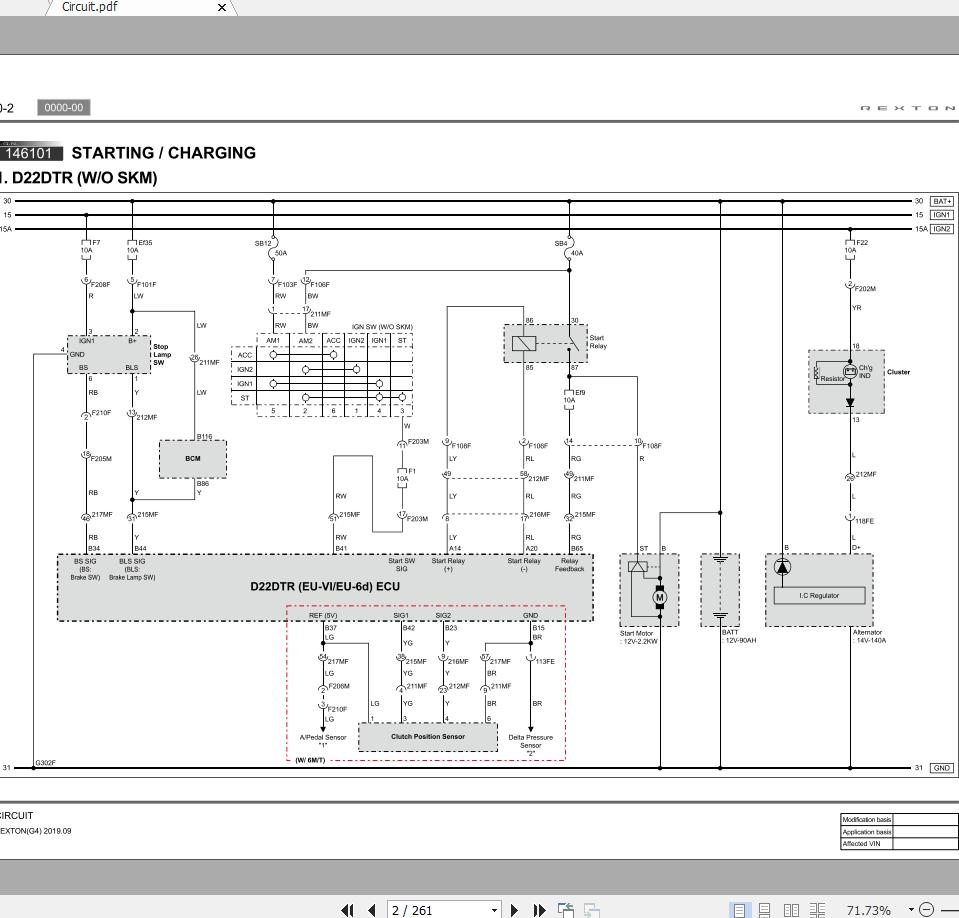
Page 55: Starting & Charging
1461-01 STARTING & CHARGING 1461-01 1) DIESEL (M/T, A/T) ~ 2002 MODEL 2) GASOLINE (M/T, A/T) ~ 2002 MODEL CIRCUIT REXTON 2004.04…
-
Page 56
1461-01 3) DIESEL (M/T, A/T) 2003 MODEL (W/ XDi) ~ 4) GASOLINE (M/T, A/T) 2003 MODEL (W/ XDi) ~ CIRCUIT REXTON 2004.04… -
Page 57
2820-01 (1) CONNECTOR INFORMATION (2) CONNECTOR IDENTIFICATION SYMBOL & PIN NUMBER POSITION CIRCUIT REXTON 2004.04… -
Page 58: Preheating Circuit
2820-01 PREHEATING UNIT CIRCUIT 2820-11 1) ~ 2002 MODEL 2) 2003 MODEL ~ CIRCUIT REXTON 2004.04…
-
Page 59
1792-01 3) XDi (1) CONNECTOR INFORMATION (2) CONNECTOR IDENTIFICATION SYMBOL & PIN NUMBER POSITION CIRCUIT REXTON 2004.04… -
Page 60: Egr (Exhaust Gas Recirculation) Control Circuit (Dsl)
1792-01 (EXHAUST RECIRCULATION) 1792-01 CONTROL CIRCUIT (DSL) 1) GENERAL ~ 2002 MODEL 2) EURO ~ 2002 MODEL CIRCUIT REXTON 2004.04…
-
Page 61
1491-01 3) HUBER EGR (1) CONNECTOR INFORMATION (2) CONNECTOR IDENTIFICATION SYMBOL & PIN NUMBER POSITION CIRCUIT REXTON 2004.04… -
Page 62: Ecu (Electronic Control Unit) (E23)
1491-01 OVPR, FUEL PUMP, CANISTER PURGE VALVE, O2 SENSOR, SPARK PLUG, SENSOR (CAM SHAFT POSITION, MAP, NTC, CRANK SHAFT POSITION,THROTTLE MOTOR, AIR TEMP, PEDAL MODULE CIRCUIT ~ 2002 MODEL KNOCK), CAM SHIFT ACTUATOR CIRCUIT ~ 2002 MODEL CIRCUIT REXTON 2004.04…
-
Page 63
0-11 1491-01 (1) CONNECTOR INFORMATION DIGITAL CLOCK, ENG TEMP SENSOR, IMMOBILIZER CIRCUIT ~ 2002 MODEL (2) CONNECTOR IDENTIFICATION SYMBOL & PIN NUMBER POSITION CIRCUIT REXTON 2004.04… -
Page 64
4) OVPR, FUEL PUMP, CANISTER PURGE VALVE, O2 SENSOR, 5) SPARK PLUG, SENSOR (CAM SHAFT POSITION, MAP, NTC, CRANK SHAFT POSITION, THROTTLE MOTOR, AIR TEMP, KNOCK), CAM PEDAL MODULE CIRCUIT 2003 MODEL ~ SHIFT ACTUATOR CIRCUIT 2003 MODEL ~ CIRCUIT REXTON 2004.04… -
Page 65
0-13 1491-01 6) DIGITAL CLOCK, ENG TEMP SENSOR, IMMOBILIZER CIRCUIT (1) CONNECTOR INFORMATION 2003 MODEL ~ (2) CONNECTOR IDENTIFICATION SYMBOL & PIN NUMBER POSITION CIRCUIT REXTON 2004.04… -
Page 66: Ecu (Electronic Control Unit) (E28, E32)
ECU (ELECTRONIC CONTROL UNIT) (E28, E32) 1491-01 OVPR, FUEL PUMP, CANISTER PURGE VALVE, PEDAL SPARK PLUG, SENSOR (CAM SHAFT POSITION, NTC, CRANK SHAFT POSITION,THROTTLE MOTOR & SENSOR, KNOCK), CAM SHIFT MODULE CIRCUIT ~ 2002 MODEL ACTUATOR, RESONANCE FLAPCIRCUIT ~ 2002 MODEL CIRCUIT REXTON 2004.04…
-
Page 67
0-15 1491-01 DIGITAL CLOCK, ENG TEMP SENSOR, IMMOBILIZER CIRCUIT 4) O2 SENSOR ~ 2002 MODEL ~ 2002 MODEL CIRCUIT REXTON 2004.04… -
Page 68
0-16 1491-01 (1) CONNECTOR INFORMATION (2) CONNECTOR IDENTIFICATION SYMBOL & PIN NUMBER POSITION CIRCUIT REXTON 2004.04… -
Page 69
0-17 1491-01 OVPR, FUEL PUMP, CANISTER PURGE VALVE, PEDAL SPARK PLUG, SENSOR(CAM SHAFT POSITION, NTC, CRANK SHAFT POSITION,THROTTLE MOTOR & SENSOR, KNOCK), CAM SHIFT MODULE CIRCUIT 2003 MODEL ~ ACTUATOR, RESONANCE FLAPCIRCUIT 2003 MODEL ~ CIRCUIT REXTON 2004.04… -
Page 70
0-18 1491-01 DIGITAL CLOCK, ENG TEMP SENSOR, IMMOBILIZER CIRCUIT O2 SENSOR 2003 MODEL ~ 2003 MODEL ~ CIRCUIT REXTON 2004.04… -
Page 71
0-19 1491-01 (1) CONNECTOR INFORMATION (2) CONNECTOR IDENTIFICATION SYMBOL & PIN NUMBER POSITION CIRCUIT REXTON 2004.04… -
Page 72: Ecu(Xdi)
0-20 1491-01 ECU(XDi) 1491-01 MAIN RLY, PEDAL MODULE, SENSOR, FUEL FILTER WARNING LAMP, IMMOBILIZER, SENSOR(FUEL VALVE(TURBO CHANGER BOOSTER, VACUUM PRESSURE, CAM SHAFT, BOOSTER PRESSURE, CRANK MODULE, INLETMETERING VALVE) SHAFT, KNOCK,WATER PUMP, FUEL TEMP) CIRCUIT REXTON 2004.04…
-
Page 73
0-21 8210-01 3) INJECTOR, CAN LINE (1) CONNECTOR INFORMATION (2) CONNECTOR IDENTIFICATION SYMBOL & PIN NUMBER POSITION CIRCUIT REXTON 2004.04… -
Page 74: Diagnosis Circuit
0-22 8210-01 DIAGNOSIS CIRCUIT 8211-01 1) ~ 2002 MODEL 2) 2003~ MODEL CIRCUIT REXTON 2004.04…
-
Page 75
0-23 3110-01 3) XDi (1) CONNECTOR INFORMATION (2) CONNECTOR IDENTIFICATION SYMBOL & PIN NUMBER POSITION CIRCUIT REXTON 2004.04… -
Page 76: Tcu(Transmission Control Unit 4-Speed)
0-24 3110-01 TCU(TRANSMISSION CONTROL UNIT 4-SPEED 3110-01 1) DSL ~ 2002 MODEL 2) GSL ~ 2002 MODEL CIRCUIT REXTON 2004.04…
-
Page 77
0-25 3110-01 3) DSL 2003 MODEL ~ 4) GSL 2003 MODEL ~ CIRCUIT REXTON 2004.04… -
Page 78
0-26 3110-01 5) 2004 MODEL (DSL) (1) CONNECTOR INFORMATION (2) CONNECTOR IDENTIFICATION SYMBOL & PIN NUMBER POSITION CIRCUIT REXTON 2004.04… -
Page 79: Tcu (5-Speed)
0-27 3110-01 TCU (5-SPEED) 3110-01 1) START MOTOR, A/T LEVER, CAN LINE (1) CONNECTOR INFORMATION (2) CONNECTOR IDENTIFICATION SYMBOL & PIN NUMBER POSITION CIRCUIT REXTON 2004.04…
-
Page 80
0-28 3410-01 2) SOLENOID OIL TEMP SENSOR, SPEED SENSOR (1) CONNECTOR INFORMATION (2) CONNECTOR IDENTIFICATION SYMBOL & PIN NUMBER POSITION CIRCUIT REXTON 2004.04… -
Page 81: Tccu (Transfercase Control Unit)
0-29 3410-01 TCCU (TRANSFERCASE CONTROL UNIT) 3410-01 1) ~ 2002 MODEL 2) 2003 MODEL CIRCUIT REXTON 2004.04…
-
Page 82
0-30 3410-01 3) 2004 MODEL ~ 4) XDi CIRCUIT REXTON 2004.04… -
Page 83
0-31 3232-34 1) CONNECTOR INFORMATION 2) CONNECTOR IDENTIFICATION SYMBOL & PIN NUMBER POSITION CIRCUIT REXTON 2004.04… -
Page 84: Tod(Torque On Demand)
0-32 3232-34 TOD(TORQUE ON DEMAND) 3232-34 1) ~ 2002 MODEL 2) 2003 MODEL ~ CIRCUIT REXTON 2004.04…
-
Page 85
0-33 4892-01 3) XDi (1) CONNECTOR INFORMATION (2) CONNECTOR IDENTIFICATION SYMBOL & PIN NUMBER POSITION CIRCUIT REXTON 2004.04… -
Page 86: Brake System
0-34 4892-01 BRAKE SYSTEM 4892-01 1) ABS & ABS/ABD 5.3 II 2) ABS(TEVES) CIRCUIT REXTON 2004.04…
-
Page 87
0-35 4892-01 3) ABS/ESP(TEVES) (1) WHEEL SPEED SENSOR, STOP LAMP SW, DIAGNOSIS, WARNING LAMP (2) BRAKE PRESSURE SENSOR, SWAS, SENSOR CLUSTER, ESP OFF SW CIRCUIT REXTON 2004.04… -
Page 88
0-36 3110-01 A. CONNECTOR INFORMATION B. CONNECTOR IDENTIFICATION SYMBOL & PIN NUMBER POSITION CIRCUIT REXTON 2004.04… -
Page 89: A/T Shift Lock Circuit
0-37 8810-01 A/T SHIFT LOCK CIRCUIT 3110-01 (1) CONNECTOR INFORMATION (2) CONNECTOR IDENTIFICATION SYMBOL & PIN NUMBER POSITION CIRCUIT REXTON 2004.04…
-
Page 90: Air Bag & Side Air-Bag Circuit
0-38 8010-01 8810-01 AIR BAG & SIDE AIR-BAG CIRCUIT (1) CONNECTOR INFORMATION (2) CONNECTOR IDENTIFICATION SYMBOL & PIN NUMBER POSITION CIRCUIT REXTON 2004.04…
-
Page 91: Cluster
0-39 8010-01 CLUSTER 8010-01 1) POWER SUPPLY, GROUND, LAMP (FUEL LOW WARNING, 4H, 2) WARNING LAMP, DEFOGGER CIRCUIT ~ 2002 MODEL 4L) CIRCUI ~ 2002 MODEL CIRCUIT REXTON 2004.04…
-
Page 92
0-40 8010-01 POWER SUPPLY, GROUND, LAMP (FUEL LOW WARNING, 4H, 4) WARNING LAMP, DEFOGGER CIRCUIT 2003 MODEL ~ 4L) CIRCUIT 2003 MODEL ~ CIRCUIT REXTON 2004.04… -
Page 93
0-41 8010-01 3) XDi GAUGE(SPEED, RPM, FUEL, TEMP), WARNING(FUEL, DR OPEN, FUEL WARNING(BAT CHANGE OIL, BRAKE, EGR CHECK, AIR BAG, SSPS, FILTER, ABS/ESP) SEAT BELT), TURNSIGNAL DEFOGGER CIRCUIT REXTON 2004.04… -
Page 94
0-42 8010-01 A. CONNECTOR INFORMATION B. CONNECTOR IDENTIFICATION SYMBOL & PIN NUMBER POSITION CIRCUIT REXTON 2004.04… -
Page 95: Multi Meter Circuit
0-43 8611-09 MULTI METER CIRCUIT 8010-01 (1) CONNECTOR INFORMATION (2) CONNECTOR IDENTIFICATION SYMBOL & PIN NUMBER POSITION CIRCUIT REXTON 2004.04…
-
Page 96: Rain Sensing Wiper Circuit
0-44 8611-09 RAIN SENSING WIPER CIRCUIT 8611-09 1) ~ 2002 MODEL (1) CONNECTOR INFORMATION (2) CONNECTOR IDENTIFICATION SYMBOL & PIN NUMBER POSITION CIRCUIT REXTON 2004.04…
-
Page 97
0-45 7410-04 2) XDi, 2003 MODEL ~ (1) CONNECTOR INFORMATION (2) CONNECTOR IDENTIFICATION SYMBOL & PIN NUMBER POSITION CIRCUIT REXTON 2004.04… -
Page 98: Power Seat Circuit
0-46 7410-32 POWER SEAT CIRCUIT (1) CONNECTOR INFORMATION 7410-04 (2) CONNECTOR IDENTIFICATION SYMBOL & PIN NUMBER POSITION CIRCUIT REXTON 2004.04…
-
Page 99: Frt Seat Warmer(W/Omemory)
0-47 8410-30 FRT SEAT WARMER(W/O MEMORY) 7410-32 (1) CONNECTOR INFORMATION (2) CONNECTOR IDENTIFICATION SYMBOL & PIN NUMBER POSITION CIRCUIT REXTON 2004.04…
-
Page 100: Power O/Side Mirror, Defogger Seat Warmer Circuit(W/ Memory)
0-48 8410-30 P OWER O/SIDE MIRROR, DEFOGGER SEAT 8410-30 WARMER CIRCUIT(W/ MEMORY) (1) CONNECTOR INFORMATION (2) CONNECTOR IDENTIFICATION SYMBOL & PIN NUMBER POSITION CIRCUIT REXTON 2004.04…
-
Page 101: Power O/Side Mirror, Defogger Circuit (W/Omemory)
0-49 8410-30 POWER O/SIDE MIRROR, DEFOGGER CIRCUIT 8410-30 (W/O MEMORY) 1) ~ 2002 MODEL (1) CONNECTOR INFORMATION (2) CONNECTOR IDENTIFICATION SYMBOL & PIN NUMBER POSITION CIRCUIT REXTON 2004.04…
-
Page 102
0-50 8710-01 2) XDi (1) CONNECTOR INFORMATION (2) CONNECTOR IDENTIFICATION SYMBOL & PIN NUMBER POSITIO CIRCUIT REXTON 2004.04… -
Page 103: Central Door Locking System
0-51 7410-00 CENTRAL DOOR LOCKING SYSTEM 8710-01 (1) CONNECTOR INFORMATION (2) CONNECTOR IDENTIFICATION SYMBOL & PIN NUMBER POSITION CIRCUIT REXTON 2004.04…
-
Page 104: Seat Belt, Tension Reducer Circuit (2002 Model Only)
0-52 7410-04 SEAT BELT, TENSION REDUCER CIRCUIT 7410-00 (2002 MODEL ONLY) (1) CONNECTOR INFORMATION (2) CONNECTOR IDENTIFICATION SYMBOL & PIN NUMBER POSITION CIRCUIT REXTON 2004.04…
-
Page 105: Passenger Power Seat Circuit
0-53 8310-10 PASSENGER POWER SEAT CIRCUIT 7410-04 (1) CONNECTOR INFORMATION (2) CONNECTOR IDENTIFICATION SYMBOL & PIN NUMBER POSITION CIRCUIT REXTON 2004.04…
-
Page 106: Auto Light Control Circuit
0-54 8310-10 AUTO LIGHT CONTROL CIRCUIT 8310-10 1) ~ 2002 MODEL (1) CONNECTOR INFORMATION (2) CONNECTOR IDENTIFICATION SYMBOL & PIN NUMBER POSITION CIRCUIT REXTON 2004.04…
-
Page 107
0-55 8711-02 2) XDi (1) CONNECTOR INFORMATION (2) CONNECTOR IDENTIFICATION SYMBOL & PIN NUMBER POSITION CIRCUIT REXTON 2004.04… -
Page 108: Stics ~ 2002 Model
0-56 8711-02 STICS ~ 2002 MODEL 8711-02 POWER SUPPLY, GND, CHIME BELL, BUZZER, WARNING FRT WIPER, DR SWITCH, LAMP (ROOM, MAP) CIRCUIT LAMP (PARKING BRAKE, SEATBELT) CIRCUIT CIRCUIT REXTON 2004.04…
-
Page 109
0-57 8711-02 DR LOCK, DEFOGGER, POWER WINDOW CIRCUIT (1) CONNECTOR INFORMATION (2) CONNECTOR IDENTIFICATION SYMBOL & PIN NUMBER POSITION CIRCUIT REXTON 2004.04… -
Page 110: Stics 2003 Model
0-58 8711-02 STICS 2003 MODEL 8711-02 POWER SUPPLY, GND, CHIME BELL, BUZZER, WARNING 2) FRT WIPER, DR SWITCH, LAMP (ROOM, MAP) CIRCUIT LAMP (PARKING BRAKE, SEATBELT) CIRCUIT CIRCUIT REXTON 2004.04…
-
Page 111
0-59 8711-02 3) DR LOCK, DEFOGGER, POWER WINDOW CIRCUIT (1) CONNECTOR INFORMATION (2) CONNECTOR IDENTIFICATION SYMBOL & PIN NUMBER POSITION CIRCUIT REXTON 2004.04… -
Page 112: Stics Xdi
0-60 8711-02 STICS XDi 8711-02 POWER SUPPLY, GND, CHIME BELL, BUZZER, WARNING 2) FRT WIPER, DR SWITCH, LAMP (ROOM, MAP) CIRCUIT LAMP (PARKING BRAKE, SEATBELT) CIRCUIT CIRCUIT REXTON 2004.04…
-
Page 113
0-61 8511-05 3) DR LOCK, DEFOGGER, POWER WINDOW CIRCUIT (1) CONNECTOR INFORMATION (2) CONNECTOR IDENTIFICATION SYMBOL & PIN NUMBER POSITION CIRCUIT REXTON 2004.04… -
Page 114: Power Window Circuit
0-62 7830-02 POWER WINDOW CIRCUIT 8511-05 (1) CONNECTOR INFORMATION (2) CONNECTOR IDENTIFICATION SYMBOL & PIN NUMBER POSITION CIRCUIT REXTON 2004.04…
-
Page 115: Rear Glass Wiper & Washer Circuit
0-63 7830-02 7830-02 REAR GLASS WIPER & WASHER CIRCUIT 1) REAR GLASS WIPER & WASHER (W/O FLIP UP GLASS) 2) REAR GLASS DPS WIPER & WASHER (W/ FLIP UP GLASS) CIRCUIT REXTON 2004.04…
-
Page 116
0-64 8610-10 REAR GLASS DPS WIPER & WASHER (W/ FLIP UP GLASS) (XDi) (1) CONNECTOR INFORMATION (2) CONNECTOR IDENTIFICATION SYMBOL & PIN NUMBER POSITION CIRCUIT REXTON 2004.04… -
Page 117: Horn Circuit
0-65 7632-20 HORN CIRCUIT 8610-10 (1) CONNECTOR INFORMATION (2) CONNECTOR IDENTIFICATION SYMBOL & PIN NUMBER POSITION CIRCUIT REXTON 2004.04…
-
Page 118: Cigar Lighter Circuit
0-66 8711-02 CIGAR LIGHTER CIRCUIT 7632-20 (1) CONNECTOR INFORMATION (2) CONNECTOR IDENTIFICATION SYMBOL & PIN NUMBER POSITION CIRCUIT REXTON 2004.04…
-
Page 119: Rekes Circuit (~ 2003 Model)
0-67 7340-03 REKES CIRCUIT (~ 2003 MODEL) 8711-02 (1) CONNECTOR INFORMATION (2) CONNECTOR IDENTIFICATION SYMBOL & PIN NUMBER POSITION CIRCUIT REXTON 2004.04…
-
Page 120: Sun Roof Circuit
0-68 8310-01 SUN ROOF CIRCUIT 7340-03 (1) CONNECTOR INFORMATION (2) CONNECTOR IDENTIFICATION SYMBOL & PIN NUMBER POSITION CIRCUIT REXTON 2004.04…
-
Page 121: Head Lamp Circuit
0-69 8310-01 HEAD LAMP CIRCUIT 8310-01 (1) CONNECTOR INFORMATION (2) CONNECTOR IDENTIFICATION SYMBOL & PIN NUMBER POSITION CIRCUIT REXTON 2004.04…
-
Page 122: Head Lamp Leveling Device Circuit
0-70 8310-01 HEAD LAMP LEVELING DEVICE CIRCUIT 8310-01 (1) CONNECTOR INFORMATION (2) CONNECTOR IDENTIFICATION SYMBOL & PIN NUMBER POSITION CIRCUIT REXTON 2004.04…
-
Page 123: Drl (Day Time Running Light) Unit (Eu)
0-71 8320-01 DRL (DAY TIME RUNNING LIGHT) UNIT (EU) 8310-01 (1) CONNECTOR INFORMATION (2) CONNECTOR IDENTIFICATION SYMBOL & PIN NUMBER POSITION CIRCUIT REXTON 2004.04…
-
Page 124: Tail Lamp Circuit
0-72 8320-01 TAIL LAMP CIRCUIT 8320-01 1) ~ 2002 MODEL 2) 2003 MODEL CIRCUIT REXTON 2004.04…
-
Page 125
0-73 8310-01 3) XDi (1) CONNECTOR INFORMATION (2) CONNECTOR IDENTIFICATION SYMBOL & PIN NUMBER POSITION CIRCUIT REXTON 2004.04… -
Page 126: Turn Signal & Hazard Lamp Circuit
0-74 8310-01 8310-01 TURN SIGNAL & HAZARD LAMP CIRCUIT 1) ~ 2002 MODEL 2) 2003 MODEL CIRCUIT REXTON 2004.04…
-
Page 127
0-75 8310-23 3) XDi (1) CONNECTOR INFORMATION (2) CONNECTOR IDENTIFICATION SYMBOL & PIN NUMBER POSITION CIRCUIT REXTON 2004.04… -
Page 128: Fog Lamp Circuit
0-76 8310-23 FOG LAMP CIRCUIT 8310-23 1) ~ 2002 MODEL (1) CONNECTOR INFORMATION (2) CONNECTOR IDENTIFICATION SYMBOL & PIN NUMBER POSITION CIRCUIT REXTON 2004.04…
-
Page 129
0-77 8320-01 2) XDi (1) CONNECTOR INFORMATION (2) CONNECTOR IDENTIFICATION SYMBOL & PIN NUMBER POSITION CIRCUIT REXTON 2004.04… -
Page 130: Stop & Back Up Lamp Circuit
0-78 7770-08 8320-01 STOP & BACK UP LAMP CIRCUIT (1) CONNECTOR INFORMATION (2) CONNECTOR IDENTIFICATION SYMBOL & PIN NUMBER POSITION CIRCUIT REXTON 2004.04…
-
Page 131: Interior Lamp Circuit
0-79 7770-03 INTERIOR LAMP CIRCUIT (1) CONNECTOR INFORMATION 7770-08 (2) CONNECTOR IDENTIFICATION SYMBOL & PIN NUMBER POSITION CIRCUIT REXTON 2004.04…
-
Page 132: Auto Dimming Room Mirror Circuit
0-80 8910-02 AUTO DIMMING ROOM MIRROR CIRCUIT 7770-03 (1) CONNECTOR INFORMATION (2) CONNECTOR IDENTIFICATION SYMBOL & PIN NUMBER POSITION CIRCUIT REXTON 2004.04…
-
Page 133: Audio, Digital Ciock Circuit
0-81 8931-01 AUDIO, DIGITAL CIOCK CIRCUIT (1) CONNECTOR INFORMATION 8910-02 (2) CONNECTOR IDENTIFICATION SYMBOL & PIN NUMBER POSITION CIRCUIT REXTON 2004.04…
-
Page 134: Audio(Multi Vision)
0-82 8931-01 AUDIO(MULTI VISION) 8931-01 1) HEAD UNIT, 2CH EXT AMP, REMOCON, NAVI UNIT, GPS (1) CONNECTOR INFORMATION (2) CONNECTOR IDENTIFICATION SYMBOL & PIN NUMBER POSITION CIRCUIT REXTON 2004.04…
-
Page 135
0-83 6810-18 2) HEAD UNIT, TUNER UNIT, VCD CHANGER (1) CONNECTOR INFORMATION (2) CONNECTOR IDENTIFICATION SYMBOL & PIN NUMBER POSITION CIRCUIT REXTON 2004.04… -
Page 136: Air-Con (Manual, Dsl) ~ 2002 Model
0-84 6810-18 AIR-CON (MANUAL, DSL) ~ 2002 MODEL 6810-18 1) ACTUATOR (MODE, AIR MIX), BLOWER UNIT CIRCUIT 2) INTAKE MOTOR, BLOWER MOTOR CIRCUIT CIRCUIT REXTON 2004.04…
-
Page 137: Air-Con (Manual, Dsl) 2004 Model
0-85 6810-18 AIR-CON (MANUAL, DSL) 2004 MODEL ~ 6810-18 1) ACTUATOR (MODE, AIR MIX), BLOWER UNIT CIRCUIT 2) INTAKE MOTOR, BLOWER MOTOR CIRCUIT CIRCUIT REXTON 2004.04…
-
Page 138: Air-Con (Manual, Dsl) Xdi
0-86 6810-18 AIR-CON (MANUAL, DSL) XDi 6810-18 1) ACTUATOR (MODE, AIR MIX), BLOWER UNIT CIRCUIT 2) INTAKE MOTOR, BLOWER MOTOR CIRCUIT CIRCUIT REXTON 2004.04…
-
Page 139
0-87 6810-18 (1) CONNECTOR INFORMATION (2) CONNECTOR IDENTIFICATION SYMBOL & PIN NUMBER POSITION CIRCUIT REXTON 2004.04… -
Page 140: Fatc (Full Auto Temperature Control)
0-88 6810-18 FATC (FULL AUTO TEMPERATURE CONTROL) 6810-18 CIRCUIT DIESEL 1) AIR MIX ACTUCTOR, SENSOR (SUN, AMBIENT, INCAR, 2) ACTURATOR (MODE, INTAKE) CIRCUIT WATER TEMP) CIRCUIT CIRCUIT REXTON 2004.04…
-
Page 141: Fatc (Full Auto Temperature Control) Circuit Gasoline & Xdi
0-89 6810-18 FATC (FULL AUTO TEMPERATURE CONTROL) 6810-18 CIRCUIT GASOLINE & XDi AIR MIX ACTUCTOR, SENSOR (SUN, AMBIENT, INCAR, 2) ACTURATOR (MODE, INTAKE) CIRCUIT WATER TEMP) CIRCUIT CIRCUIT REXTON 2004.04…
-
Page 142
0-90 7010-06 (1) CONNECTOR INFORMATION (2) CONNECTOR IDENTIFICATION SYMBOL & PIN NUMBER POSITION CIRCUIT REXTON 2004.04… -
Page 143: Immobilizer (Dsl)
0-91 8790-01 IMMOBILIZER (DSL) 7010-06 (1) CONNECTOR INFORMATION (2) CONNECTOR IDENTIFICATION SYMBOL & PIN NUMBER POSITION CIRCUIT REXTON 2004.04…
-
Page 144: Parking Aid Circuit
0-92 4610-00 PARKING AID CIRCUIT 8790-01 (1) CONNECTOR INFORMATION (2) CONNECTOR IDENTIFICATION SYMBOL & PIN NUMBER POSITION CIRCUIT REXTON 2004.04…
-
Page 145: Trailer Connector Circuit
0-93 6810-15 TRAILER CONNECTOR CIRCUIT 4610-00 (1) CONNECTOR INFORMATION (2) CONNECTOR IDENTIFICATION SYMBOL & PIN NUMBER POSITION CIRCUIT REXTON 2004.04…
-
Page 146: Coefficient)
0-94 6910-01 P .T.C HEATER(POSITIVE TEMPERATURE 6810-15 COEFFICIENT) (1) CONNECTOR INFORMATION (2) CONNECTOR IDENTIFICATION SYMBOL & PIN NUMBER POSITION CIRCUIT REXTON 2004.04…
-
Page 147: Ffh (Fuel Fired Heater)
0-95 4620-12 FFH (FUEL FIRED HEATER) 6910-01 (1) CONNECTOR INFORMATION (2) CONNECTOR IDENTIFICATION SYMBOL & PIN NUMBER POSITION CIRCUIT REXTON 2004.04…
-
Page 148
0-96 4620-12 S.S.P.S 4620-12 (1) CONNECTOR INFORMATION (2) CONNECTOR IDENTIFICATION SYMBOL & PIN NUMBER POSITION CIRCUIT REXTON 2004.04… -
Page 149
VEHICLE GENERAL 0000-00 VEHICLE GENERAL VEHICLE GENERAL 1. VEHICLE SPECIFICATIONS….2. VEHICLE IDENTIFICATION….3. GUIDELINES FOR SERVICE WORK SAFETY……….4. LIFTING POINTS……..5. TIGHTENING TORQUE OF STANDARD BOLTS……….. 6. CLEANNESS………. -
Page 151: Vehicle Specifications
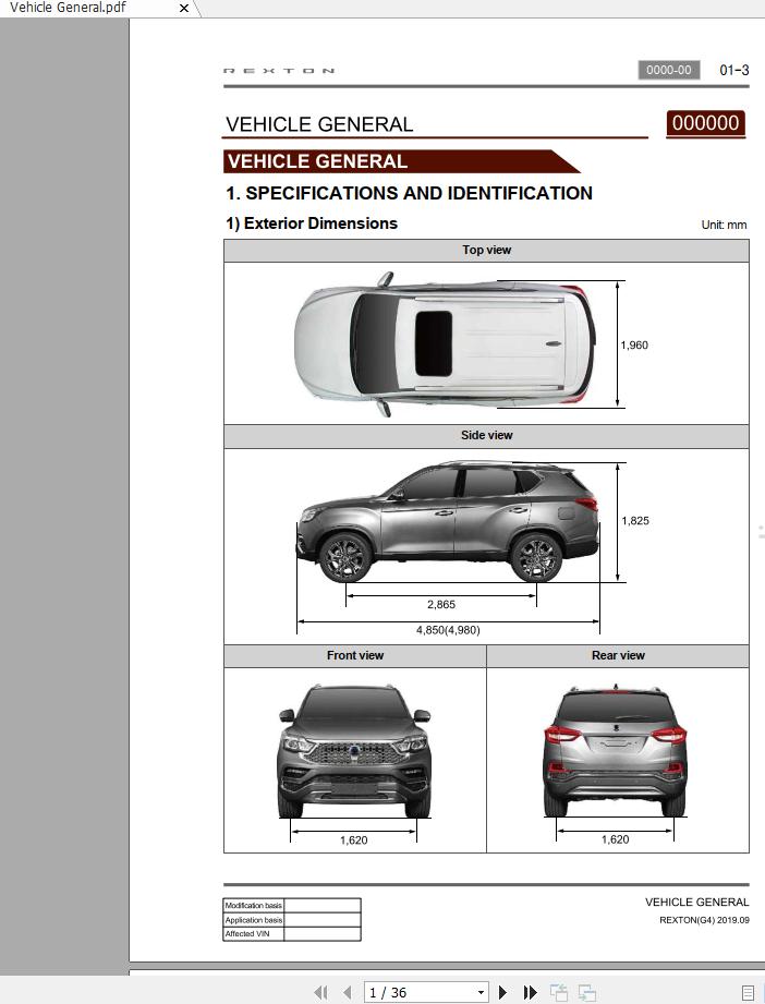
01-3 0000-00 0000-00 VEHICLE GENERAL GENERAL 1. VEHICLE SPECIFICATIONS 1) Vehicle Dimension VEHICLE GENERAL undefined…
-
Page 152
01-4 0000-00 2) Specifications VEHICLE GENERAL undefined… -
Page 153
01-5 0000-00 ▶Specifications (Cont’d) VEHICLE GENERAL undefined… -
Page 154
01-6 0000-00 3) Maintenance ▶Major Components and Service Interval VEHICLE GENERAL undefined… -
Page 155
01-7 0000-00 ▶Lubrication Chart ※ Please contact Ssangyong Dealer for approved alternative fluid. In only case not available MB 229.1 or 229.3, API or ACEA oil may be accepted, ※※ however it would rather recommend to shorten the change interval around 30%. -
Page 156: Vehicle Identification
Vehicle identification number (VIN) is is on the right front axle upper frame. [KPTPOA19S1P 122357] K.. Nation (K: Korea) P .. Maker Identification (P: Ssangyong Motor Company) T .. Vehicle Type (T: Passenger car — 4WD) P .. Line Models (P: Rexton) O . Body Type (O: 5-door) A..
-
Page 157
01-9 0000-00 3) Engine Serial Number The engine serial number is stamped on the lower area of cylinder block in exhaust manifold side. 4) Manual Transmission Number The transmission label is affixed on the upper area of clutch housing. 5) Automatic Transmission Number The transmisson label is affixed on the right area of transmission housing. -
Page 158: Guidelines For Service Work Safety
01-10 0000-00 3. GUIDELINES FOR SERVICE WORK SAFETY 1) General To maintain and operate the vehicle under optimum state by performing safe service works, the service works should be done following correct methods procedures. Accordingly, the purpose of this manual is to prevent differences that can be caused by personal working method, skill, ways and service procedures and to allow…
-
Page 159
01-11 0000-00 2) Cautions on Inspection/Service During service works, be sure to observe below general items for your safety. For service works, be sure to disconnect battery negative (-) terminal if not starting and · inspection. · While inspecting vehicle and replacing various consumable parts, be sure to take caution not to damage vehicle and injure people. -
Page 160
01-12 0000-00 3) Guidelines on Engine Service To prevent personal injuries and vehicle damages that can be caused by mistakes during engine and unit inspection/ repair and to secure optimum engine performance and safety after service works, basic cautions and service work guidelines that can be easily forgotten during engine service works are described in. -
Page 161
01-13 0000-00 ▶ Fuel and lubrication system Painted surface of the body can be damaged or rubber products (hoes) can be corroded if engine oil and fuel are spilled over. If spilled over engine, foreign materials in air can be accumulated on the engine damaging fuel system. -
Page 162
01-14 0000-00 4) During Service Work — Inspection Before lifting up the vehicle with lift, correctly support the lifting points and lift When using a jack, park the vehicle on the level ground and block front and rear wheels. Position the jack under the frame and lift up the vehicle and then support with chassis stand before service work. -
Page 163
01-15 0000-00 Never reuse cotter pin, gasket, O-ring, oil seal, lock washer and self-locking nut. Replace them with new. If reused, normal functions cannot be maintained. Align the disassembled parts in clean according to disassembling order and group for easy assembling. According to installing positions, the bolts and nuts have different hardness and design. -
Page 164
01-16 0000-00 5) During Service Work for Electric Devices Be careful not to modify or alter electrical system and electrical device. Or there can be vehicle fire or serious damage. Be sure to disconnect battery negative (- ) terminal during every service work. Before disconnecting battery negative (-) terminal, turn off ignition key. -
Page 165: Lifting Points
01-17 0000-00 4. LIFTING POINTS 1) Lifting Positions ▶4-post lift As illustrated, position the vehicle on the 4-post lift securely and block the front and rear of each tire not to move during working. During lifting, be sure to check whether vehicle is empty Board-on lift connection device installed in front of vehicle should be positioned in front of ·…
-
Page 166: Tightening Torque Of Standard Bolts
01-18 0000-00 5. TIGHTENING TORQUE OF STANDARD BOLTS Tightening Torque By Bolt Specification ▶ Metric bolt strength is embossed on the Determine extra proper tightening torque head of each bolt. The strength of bolt if tightens with washer or packing. can be classified as 4T, 7T, 8.8T, 10.9T, If tightens bolts on the below materials, 11T and 12.9T in general.
-
Page 167: Cleanness
01-19 0000-00 6. CLEANNESS 1) Cleanness of Engine Fuel System and Service Procedures The fuel system for DI engine consists of transfer (low pressure) line and high pressure line. Its highest pressure reaches over 1600 mbar. Some components in injector and HP pump are machined with 100 μm of preciseness.
-
Page 168
01-20 0000-00 2) Job procedures Always keep the workshop and lift clean (especially, from dust). Always keep the tools clean (from oil or foreign materials). Wear a clean vinyl apron to prevent the fuzz, dust and foreign materials from getting into fuel system. -
Page 169
01-21 0000-00 Follow the job procedures. If you find a defective component, replace it with new one. Disconnect the negative battery cable. Use special tools and torque wrench to perform the correct works. Once disconnected, the fuel pipes between HP pump and fuel rail and between fuel rail and each injector should be replaced with new ones. -
Page 170
01-22 0000-00 Plug the removed components with clean and undamaged sealing caps and store it into the box to keep the conditions when it was installed. Clear the high pressure offset value from scan tool after replacing the high pressure pump. To supply the fuel to transfer line of HP pump press the priming pump until it becomes hard. -
Page 171
01-23 0000-00 3) DI Engine and Its Expected Problems and Remedies Can be Caused by Water in Fuel (1) SYSTEM SUPPLEMENT AGAINST PARAFFIN SEPARATION. In case of Diesel fuel, paraffin, one of the elements, can be separated from fuel during winter and then can stick on the fuel filter blocking fuel flow and causing difficult starting finally. -
Page 173
01-3 0000-00 1113-01 ENGINE ASSEMBLY GENERAL 1. SPECIFICATIONS 1) Fastener Tightening Specifications ENGINE ASSEMBLY undefined… -
Page 174
01-4 0000-00 ▶ Fastener Tightening Specifications (Cont’d) ENGINE ASSEMBLY undefined… -
Page 175
02-3 0000-00 2211-06 FUEL SYSTEM GENERAL 1. FUEL SYSTEM SPECIFICATION ▶ Use Only Unleaded Fuel Rated at 89 Octane or Higher Fuel quality and additives contained in fuel have a significant effect on power output, drivability, and life of the engine. Fuel with too low an octane number can cause engine knock. -
Page 176
02-4 0000-00 ▶ Temperature VS Resistance FUEL SYSTEM undefined… -
Page 177
02-5 0000-00 CONFIGURATION AND PROCESS 1. FUEL SYSTEM The function of the fuel metering system is to deliver the correct amount of fuel to the engine under all operating conditions. The fuel is delivered to the engine by the individual fuel injectors mounted into the intake manifold near each cylinder. -
Page 178
02-6 0000-00 1) Starting Mode When the ignition is turned ON, the ECM turns the fuel pump relay on for 1 second. The fuel pump then builds fuel pressure. The ECM also checks the Engine Coolant Temperature (ECT) sensor and the Throttle Position (TP) sensor and determines the proper air/fuel ratio for starting the engine. -
Page 179
02-7 0000-00 7) Battery Voltage Correction Mode When battery voltage is low, the ECM can compensate for a weak spark delivered by the ignition module by using the following methods: Increasing the fuel injector pulse width. Increasing the idle speed rpm. Increasing the ignition dwell time. -
Page 182
04-3 0000-00 2411-01 EXHAUST SYSTEM OVERVIEW AND OPERATION PROCESS 1. CRANKCASE VENTILATION SYSTEM 1) Operation at Idling and Mid- Load 1 HFM Sensor 12 Crank Chamber 2 Cylinder Head Cover 13 Oil Return Pipe 3 Oil Spearation Chamber (Full-Load or Over Mid- Load) 14 Oil Pan 4 Intake Air Duct (Cross Pipe) 15 Timing Gear Case Cover… -
Page 183
04-4 0000-00 ▶ Operation at Idling and Mid- Load The throttle valve (6) is closed or very partially opened, and the vacuum pressure in intake manifold is high. The blow-by gas and the fresh air that is additionally supplied through the vent connection (D) in the crank-case in partial load gets supplied to the combustion chamber from the crank chamber (12) through the oil separation chamber (11), airconditioner bracket (10), vent line (9), and restrictor (7) mounted to the cylinder head. -
Page 184
04-5 0000-00 2) Operation When Full- Load at Partial Load 1 HFM Sensor 12 Crank Chamber 2 Cylinder Head Cover 13 Oil Return Pipe 3 Oil Spearation Chamber (Full-Load or Over Mid-Load) 14 Oil Pan 4 Intake Air Duct (Cross Pipe) 15 Timing Gear Case Cover 5 Vent Line (Full-Load or Over Mid-Load) 16 Crankcase… -
Page 185
04-6 0000-00 ▶ Operation When Full- Load at Partial Load The throttle valve (6) is partially opened or fully opened. The air flows very rapidly through the vent line (5) s connection (D) and the intake air duct when full load at partial load. Consequently, most of the low-by gases are supplied to the combustion chamber through the timing gear case cover (15), chain housing (17), oil separation chamber (3), vent line (5), throttle valve (6), and intake manifold (8). -
Page 186
05-3 0000-00 1532-24 LUBRICATION SYSTEM OVERVIEW AND OPERATION PROCESS 1. OIL CIRCULATION 1 Oil Strainer 16 Oil Supply (To Chain Tensioner) 2 Oil Pump 17 Camshaft 3 Oil Pan 18 Cam Bearing 4 Oil Non-Return Valve 19 Valve 5 Oil Filter 20 Oil Gallery (Supply Oil to Intake Tappet) 6 Oil Filter Bypass Valve 21 Oil Gallery (Supply Oil to Exhaust Tappet) -
Page 187
06-3 0000-00 1441-01 ENGINE ELECTRICAL OVERVIEW AND OPERATION PROCESS 1. IGNITION SYSTEM This ignition system does not use a conventional distributor and coil. It uses a crankshaft position sensor input to the Engine Control Module (ECM). The ECM then determines Electronic Spark Timing (EST) and triggers the electronic ignition system ignition coil. -
Page 188
NO DATA… -
Page 189
08-3 0000-00 1430-01 ENGINE CONTROLS GENERAL 1. ENGINE AND ECM PROBLEM CHECK REPORT 1) Vehicle and Customer Information 2) MIL Information 3) Problem Description ENGINE CONTROLS undefined… -
Page 190
08-4 0000-00 4) Condition When Problem Occurs ENGINE CONTROLS undefined… -
Page 191
08-5 0000-00 2. SPECIFICATIONS 1) Engine Data Display Table Condition : Warmed up, idle, P/N or neutral ENGINE CONTROLS undefined… -
Page 192
08-6 0000-00 2) Fastener Tightening Specifications ENGINE CONTROLS undefined… -
Page 193
08-7 0000-00 OVERVIEW AND OPERATION PROCESS 1. SCHEMATIC AND ROUTING DIAGRAMS 1) ECM Wiring Diagram (2.3L DOHC — 1 of 7) (MSE 3.53D) ENGINE CONTROLS undefined… -
Page 194
08-8 0000-00 2) ECM Wiring Diagram (2.3L DOHC — 2 of 7) (MSE 3.53D) ENGINE CONTROLS undefined… -
Page 195
08-9 0000-00 3) ECM Wiring Diagram (2.3L DOHC — 3 of 7) (MSE 3. 53D) ENGINE CONTROLS undefined… -
Page 196
08-10 0000-00 4) ECM Wiring Diagram (2.3L DOHC — 4 of 7) (MSE 3.53D) ENGINE CONTROLS undefined… -
Page 197
08-11 0000-00 5) ECM Wiring Diagram (2.3L DOHC — 5 of 7) (MSE 3.53D) ENGINE CONTROLS undefined… -
Page 198
08-12 0000-00 6) ECM Wiring Diagram (2.3L DOHC — 6 of 7) (MSE 3.53D) ENGINE CONTROLS undefined… -
Page 199
08-13 0000-00 7) ECM Wiring Diagram (2.3L DOHC — 7 of 7) (MSE 3.53D) ENGINE CONTROLS undefined… -
Page 200
08-47 0000-00 ENGINE CONTROL MODULE 1491-01 Disconnect the negative battery cable. Remove cowl side trim form passenger side. Re-er to Section 9G, Interior trim. Remove the four securing nuts for the Engine Control Module (ECM) from the mounting bracket. 10 Nm (89 lb-in) Pull out the ECM from the bracket. -
Page 201
09-3 8510-23 8510-23 CRUISE CONTROL SYSTEM OVERVIEW AND OPERATION PROCESS 1. CRUISE CONTROL SWITCH The purpose of the cruise control system is to automatically maintain a vehicle speed set by the driver, without depressing the accelerator pedal. The cruise control switch is located under the right side of the steering wheel, and when this switch is operating «AUTO CRUISE»… -
Page 202
09-4 8510-23 1) When To Use Use the cruise control system only when (a) the traffic is not jammed, (b) driving on motorways or highways where there is no sudden change in the driving condition due to traffic lights, pedestrian, etc. Use the cruise control system only when driving on motorways or highways. -
Page 203
09-5 8510-23 2. CIRCUIT DIAGRAM 1) Configuration CRUISE CONTROL SYSTEM undefined… -
Page 204
09-6 8510-23 3. HOW TO OPERATE CRUISE CONTROL SWITCH 1) How To Set Speed To operate the cruise control system, accelerate the vehicle to the speed within the specified range below with depressing the accelerator pedal. — Cruise control operating range: between 36 km/h (22.37 mph) and 150 km/h (93.207 mph) When the desired speed is reached, which should be within the above range, push up the cruise control switch lever to ACCEL side (upwards arrow), or push down the switch lever to DECEL side (downwards arrow). -
Page 205
09-7 8510-23 2) Accelerating with the Cruise Control System (1) While the cruise control system is running To increase the set speed, push up the cruise control switch lever to ACCEL side and hold it until the desired speed is reached without depressing the accelerator pedal. When the desired speed is set, release the switch lever. -
Page 206
09-8 8510-23 3) Decelerating with the Cruise Control System (1) While the cruise control system is running To decrease the set speed, push down the cruise control switch lever to DECEL side and hold it until the desired speed is reached without depressing the brake pedal. But the cruise control system cannot maintain the cruise function at less than 34 km/h (21.13 mph). -
Page 207
09-9 8510-23 4) Recovery of Set Speed (RESUME) Even if the cruise control is cancelled, the previous set cruise speed can be recovered by operating the cruise control switch lever like below: — Pull the switch lever in the arrow direction shown in the illustration. This RESUME function works only when the vehicle speed is more than 36 km/h (22.37 mph) without using the accelerator or brake pedal. -
Page 208
09-10 8510-23 5) Normal Cancellation of the Cruise Control (OFF ↔ ON) The cruise control system will be cancelled when the button on the side of the switch is pressed, or when one of the following conditions is met: When the brake pedal is depressed or ESP is activated. When the vehicle speed is less than 34 km/h (21.13 mph). -
Page 209
01-3 0000-00 1113-01 ENGINE ASSEMBLY GENERAL 1. SPECIFICATIONS 1) Fastener Tightening Specifications ENGINE ASSEMBLY undefined… -
Page 210
01-4 0000-00 ▶ Fastener Tightening Specifications (Cont’d) ENGINE ASSEMBLY undefined… -
Page 211
02-3 0000-00 2211-06 FUEL SYSTEM GENERAL 1. FUEL SYSTEM SPECIFICATION ▶ Use Only Unleaded Fuel Rated at 89 Octane or Higher Fuel quality and additives contained in fuel have a significant effect on power output, drivability, and life of theengine. Fuel with too low an octane number can cause engine knock. -
Page 212
02-4 0000-00 ▶ Temperature VS Resistance FUEL SYSTEM REXTON 2004.12… -
Page 213
02-5 0000-00 OVERVIEW AND OPERATION PROCESS 1. FUEL SYSTEM The function of the fuel metering system is to deliver the correct amount of fuel to the engine under all operating conditions. The fuel is delivered to the engine by the individual fuel injectors mounted into the intake manifold near each cylinder. -
Page 214
02-6 0000-00 ▶ Run Mode The run mode has two conditions called »open loop» and »closed loop». Open Loop ▶ When the engine is first started and it is above 690 rpm, the system goes into «open loop» operation. In «open loop», the ECM ignores the signal from the O2S and calculates the air/fuel ratio based on inputs from the ECT sensor and the MAF sensor. -
Page 215
NO DATA… -
Page 216
NO DATA… -
Page 217
05-3 0000-00 1542-07 LUBRICATION SYSTEM GENERAL 1. ENGINE OIL SPECIFICATION 1 Drain Plug …….. 25 Nm (18 lb-ft) 2 Oil Filter 3 Engine Oil Filler Cap 4 Dipstick Gauge ▶ Specifications LUBRICATION SYSTEM undefined… -
Page 218
05-4 0000-00 OVERVIEW AND OPERATION PROCESS 1. OIL CIRCULATION 1 Oil Pump 20 Oil Supply (To Exhaust Camshaft Bearing) 2 Oil Gallery (to oil filter) 21 Oil Supply (To Intake Camshaft Bearing) 3 Oil Filter 22 Oil Gallery (Oil Supply to Exhaust Valve Tappet) 4 Oil Pressure Switch 23 Oil Gallery (Oil Supply to Intake Valve Tappet) 5 Main Oil Gallery… -
Page 219
06-3 0000-00 1441-01 ENGINE ELECTRICAL OVERVIEW AND OPERATIONPROCESS 1. IGNITION SYSTEM This ignition system does not use a conventional distributor and coil. It uses a crankshaft position sensor input to the Engine Control Module (ECM). The ECM then determines Electronic Spark Timing (EST) and triggers the electronic ignition system ignition coil. This type of distributorless ignition system uses a »waste spark»… -
Page 220
NO DATA… -
Page 221
08-3 0000-00 1430-01 ENGINE CONTROLS GENERAL 1. SPECIFICATIONS 1) Engine Data Display Table ENGINE CONTROLS undefined… -
Page 222
08-4 0000-00 2) Fastener Tightening Specifications ENGINE CONTROLS undefined… -
Page 223
08-5 0000-00 OVERVIEW AND OPERATION PROCESS 1. SCHEMATIC AND ROUTING DIAGRAMS 1) ECM Wiring Diagram (3.2L DOHC — 1 of 7) (MSE 3.63D) ENGINE CONTROLS undefined… -
Page 224
08-6 0000-00 2) ECM Wiring Diagram (3.2L DOHC — 2 of 7) (MSE 3.63D) ENGINE CONTROLS undefined… -
Page 225
08-7 0000-00 3) ECM Wiring Diagram (3.2L DOHC — 3 of 7) (MSE 3.63D) ENGINE CONTROLS undefined… -
Page 226
08-8 0000-00 4) ECM Wiring Diagram (3.2L DOHC — 4 of 7) (MSE 3.63D) ENGINE CONTROLS undefined… -
Page 227
08-9 0000-00 5) ECM Wiring Diagram (3.2L DOHC — 5 of 7) (MSE 3.63D) ENGINE CONTROLS undefined… -
Page 228
08-10 0000-00 6) ECM Wiring Diagram (3.2L DOHC — 6 of 7) (MSE 3.63D) ENGINE CONTROLS undefined… -
Page 229
08-11 0000-00 7) ECM Wiring Diagram (3.2L DOHC — 7 of 7) (MSE 3.63D) ENGINE CONTROLS undefined… -
Page 230
09-3 8510-23 8510-23 CRUISE CONTROL SYSTEM OVERVIEW AND OPERATION PROCESS 1. CRUISE CONTROL SWITCH The purpose of the cruise control system is to automatically maintain a vehicle speed set by the driver, without depressing the accelerator pedal. The cruise control switch is located under the right side of the steering wheel, and when this switch is operating «AUTO CRUISE»… -
Page 231
09-4 8510-23 1) When To Use Use the cruise control system only when (a) the traffic is not jammed, (b) driving on motorways or highways where there is no sudden change in the driving condition due to traffic lights, pedestrian, etc. Use the cruise control system only when driving on motorways or highways. -
Page 232
09-5 8510-23 2. CIRCUIT DIAGRAM 1) Configuration CRUISE CONTROL SYSTEM undefined… -
Page 233
09-6 8510-23 3. HOW TO OPERATE CRUISE CONTROL SWITCH 1) How To Set Speed To operate the cruise control system, accelerate the vehicle to the speed within the specified range below with depressing the accelerator pedal. — Cruise control operating range: between 36 km/h (22.37 mph) and 150 km/h (93.207 mph) When the desired speed is reached, which should be within the above range, push up the cruise control switch lever to ACCEL side (upwards arrow), or push down the switch lever to DECEL side (downwards arrow). -
Page 234
09-7 8510-23 2) Accelerating with the Cruise Control System (1) While the cruise control system is running To increase the set speed, push up the cruise control switch lever to ACCEL side and hold it until the desired speed is reached without depressing the accelerator pedal. When the desired speed is set, release the switch lever. -
Page 235
09-8 8510-23 3) Decelerating with the Cruise Control System (1) While the cruise control system is running To decrease the set speed, push down the cruise control switch lever to DECEL side and hold it until the desired speed is reached without depressing the brake pedal. But the cruise control system cannot maintain the cruise function at less than 34 km/h (21.13 mph). -
Page 236
09-9 8510-23 4) Recovery of Set Speed (RESUME) Even if the cruise control is cancelled, the previous set cruise speed can be recovered by operating the cruise control switch lever like below: — Pull the switch lever in the arrow direction shown in the illustration. This RESUME function works only when the vehicle speed is more than 36 km/h (22.37 mph) without using the accelerator or brake pedal. -
Page 237
09-10 8510-23 5) Normal Cancellation of the Cruise Control (OFF ↔ ON) The cruise control system will be cancelled when the button on the side of the switch is pressed, or when one of the following conditions is met: When the brake pedal is depressed or ESP is activated. When the vehicle speed is less than 34 km/h (21.13 mph). -
Page 238
ENGINE GENERAL 0000-00 ENGINE GENERAL GENERAL 1. STRUCTURE………. OVERVIEW AND OPERATION PROCESS 1. ENGINE CONTROLS COMPONENTS..2. INTAKE SYSTEM COMPONENTS..3. EXHAUST SYSTEM COMPONENTS..4. LUBRICATION SYSTEM COMPONENTS……..5. COOLING SYSTEM COMPONENTS..6. FUEL SYSTEM COMPONENTS….. -
Page 240: General
01-3 0000-00 0000-00 ENGINE GENERAL GENERAL 1. STRUCTURE ▶ Front view ▶ Rear view TVD (Torsional Vibration Cooling fan pulley Oil filter Damper) Aut tensioner pulley Vacuum pump Air conditioner compressor Auto tensioner Crank position sensor Power steering pump pulley Poly-groove belt EGR valve Idle pulley…
-
Page 241
01-4 0000-00 ▶ Top view Cylinder head cover Fuel pipe Booster pressure sensor Intake manifold Injector Oil separator Water outlet port Fuel return line Oil dipstic Common rail Oil filler cap EGR center pipe Fuel pressure sensor Glow plug ENGINE GENERAL undefined… -
Page 242
01-5 0000-00 ▶ Left side view ▶ Right side view Cylinder head EGR — RH (#3) pipe Turbocharger vacuum modulator Cylinder block Oil separator EGR valve vacuum modulator Oil dipstic EGR valve Drain plug HP pump Exhaust manifold Turbocharger ENGINE GENERAL undefined… -
Page 243: Overview And Operation Process
01-6 0000-00 OVERVIEW AND OPERATION PROCESS 1. ENGINE CONTROLS COMPONENTS 1) ECU Related Components ENGINE GENERAL undefined…
-
Page 244
01-7 0000-00 2) Engine And Sensors ENGINE GENERAL undefined… -
Page 245
01-8 0000-00 3) Electrical Components And Pre Heating System ENGINE GENERAL undefined… -
Page 246: Intake System Components
01-9 0000-00 2. INTAKE SYSTEM COMPONENTS ENGINE GENERAL undefined…
-
Page 247
01-10 0000-00 ▶ Intake Air Flow Chart ENGINE GENERAL undefined… -
Page 248: Exhaust System Components
01-11 0000-00 3. EXHAUST SYSTEM COMPONENTS ENGINE GENERAL undefined…
-
Page 249
01-12 0000-00 ▶ Exhaust Air Flow Chart ENGINE GENERAL undefined… -
Page 250: Lubrication System Components
01-13 0000-00 4. LUBRICATION SYSTEM COMPONENTS ENGINE GENERAL undefined…
-
Page 251
01-14 0000-00 ▶ Lubrication Flow Chart Oil pump Oil restriction (inner — φ 4 mm) Oil gallery (to oil filter) Oil supply (to exhaust camshaft) Oil filter Oil supply (to intake camshaft) Oil pressure switch Oil supply (to exhaust camshaft bearing) Main oil gallery Oil supply (to intake camshaft bearing) Oil gallery (chain tensioner side) -
Page 252: Cooling System Components
01-15 0000-00 5. COOLING SYSTEM COMPONENTS ENGINE GENERAL undefined…
-
Page 253
01-16 0000-00 ▶ Coolant Flow Chart ENGINE GENERAL undefined… -
Page 254: Fuel System Components
01-17 0000-00 6. FUEL SYSTEM COMPONENTS ENGINE GENERAL undefined…
-
Page 255
01-18 0000-00 ▶ Fuel Supply System According to input signals from various sensors, engine ECU calculates driver’s demand (position of the accelerator pedal) and then controls overall operating performance of engine and vehicle on that time. ECU receives signals from sensors via data line and then performs effective engine air-fuel ratio controls based on those signals. -
Page 256
02-3 1212-01 1212-01 ENGINE ASSEMBLY GENERAL 1. D27DT ENGINE STRUCTURE 1) Major Components in Engine and Engine Compartment The advanced electronically controlled D27DT engine that has high pressure fuel system has been introduced to this vehicle. It satisfies the strict emission regulation and provides improved output and maximum torque. -
Page 257
02-4 1212-01 2) Engine Structure Front View Rear View 1. TVD (Torsional Vibration Damper) 7. Viscos fan clutch 13. Oil filter 2. Air conditioner compressor 8. Auto tensioner pulley 14. Vacuum pump 3. Power steering pump pulley 9. Auto tensioner 15. -
Page 258
02-5 1212-01 Top View 19. Cylinder head cover 24. Fuel pipe 29. Booster pressure sensor 20. Intake manifold 25. Injector 30. PCV valve and oil separator 21. Water outlet port 26. Fuel return line 31. Oil dipstick 22. Common rail 27. -
Page 259
02-6 1212-01 Left Side View Right Side View 33. Cylinder head 38. EGR-RH (#3) pipe 42. Turbo charger booster vacuum 34. Cylinder block 39. PCV valve and oil separator modulator 35. Oil pan 40. Oil dipstick 43. EGR valve vacuum modulator 36. -
Page 260
02-7 1212-01 2. SPECIFICATIONS ENGINE ASSEMBLY undefined… -
Page 261
02-8 1212-01 3. ENGINE PERFORMANCE CURVE ▶Output and Torque ENGINE ASSEMBLY undefined… -
Page 262
02-9 1212-01 ▶Oil Temperature/Pressure and Boost Pressure ENGINE ASSEMBLY undefined… -
Page 263
02-10 1212-01 4. TIGHTENING TORQUE ENGINE ASSEMBLY undefined… -
Page 264
02-11 1212-01 ENGINE ASSEMBLY undefined… -
Page 265
02-12 1212-01 ENGINE ASSEMBLY undefined… -
Page 266
03-3 1881-01 1881-01 ENGINE FUEL SYSTEM GENERAL 1. CAUTIONS FOR DI ENGINE This chapter describes the cautions for DI engine equipped vehicle. This includes the water separation from engine, warning lights, symptoms when engine malfunctioning, causes and actions. DI Engine ▶… -
Page 267
03-4 1881-01 ▶ Priming Pump The priming pump installed in fuel pump is the device to fill the fuel into the fuel filter. When the vehicle is under the conditions as below, press the priming pump until it becomes rigid before starting the engine. -
Page 268
03-5 1881-01 ▶ Draining the Water From Fuel Filter 1. Place the water container under the fuel filter. Turn the drain plug (2) to «A» direction to drain the water. Wait until a certain amount of fuel gets out from the port, then turn the drain plug to «B»… -
Page 269
03-6 1881-01 OVERVIEW AND OPERATION PROCESS 1. FUEL INJECTION SYSTEM 1) Electronic Control of Fuel System According to input signals from various sensors, engine ECU calculates driver’s demand (position of the accelerator pedal) and then controls overall operating performance of engine and vehicle on that time. -
Page 270
03-7 1881-01 2) Composition of Fuel System Components in fuel system are designed to generate and distribute high pressure, and they are controlled electronically by engine ECU. Accordingly, fuel system is completely different from injection pump type fuel supply system on the conventional Diesel engine. The fuel injection system in common rail engine is composed of transfer pressure section that transfers fuel in low pressure, high pressure section that transfers fuel in high pressure and ECU control section. -
Page 271
03-8 1881-01 3) Hydraulic Cycle in Fuel Line (Transfer and High Pressure Line) ENGINE FUEL SYSTEM undefined… -
Page 272
03-9 1881-01 4) Components of Low Pressure Transfer Line Low pressure stage is to supply sufficient fuel to high pressure section and components are as below. Fuel tank (including strainer) Hand priming pump Fuel filter Transfer pump Other low pressure fuel hoses (1) Fuel tank Fuel tank is made of anti-corrosion material and its allowable pressure is 2 times of… -
Page 273
03-10 1881-01 (3) Fuel filter It requires more purified fuel supply than conventional diesel engine. If there are foreign materials in the fuel, fuel system including pump components, delivery valve and injector nozzles may be damaged. Fuel filter purifies fuel before it reaches to high pressure pump… -
Page 274
03-11 1881-01 5) Components of High Pressure Transfer Line In the high pressure section, sufficient fuel pressure that injectors requires will be generated and stored. The components are as below: High pressure pump Rail pressure sensor Pressure limit valve Common rail High pressure pipe Injector Fuel pressure regulating valve (IMV) -
Page 275
03-12 1881-01 (3) High pressure pipe (fuel pipe) Fuel line transfers high pressure fuel. Accordingly, it is made of steel to endure intermittent high frequency pressure changes that occur under maximum system pressure and injection stops. Injection lines between rail and injectors are all in the same length;… -
Page 276
03-13 1881-01 6) Electrical Wiring Diagram ENGINE FUEL SYSTEM undefined… -
Page 277
04-3 2313-01 2313-01 ENGINE INTAKE SYSTEM OVERVIEW AND OPERATION PROCESS 1. COMPONENTS LOCATOR ENGINE INTAKE SYSTEM undefined… -
Page 278
04-4 2313-01 2. AIR FLOWS ▶ Work Flow of Intake System ENGINE INTAKE SYSTEM undefined… -
Page 279
05-3 0000-00 0000-00 ENGINE EXHAUST SYSTEM OVERVIEW AND OPERATION PROCESS 1. COMPONENTS LOCATOR ENGINE EXHAUST SYSTEM undefined… -
Page 280
05-4 0000-00 2. EXHAUST GAS FLOWS ENGINE EXHAUST SYSTEM undefined… -
Page 281
06-3 1533-01 1533-01 ENGINE LUBRICATION SYSTEM GENERAL 1. SPECIFICATIONS ※ Severe condition: When most trips include extended idling and/or frequent low-speed operation as in stop- and-go traffic. When most trips are less than 6 km (Operating when outside temperatures remain below freezing and when most trips are less than 16 km) When operating in dusty, sandy and salty areas In hilly or moutainous terrain… -
Page 282
06-4 1533-01 OVERVIEW AND OPERATION PROCESS 1. COMPONENTS LOCATOR ENGINE LUBRICATION SYSTEM undefined… -
Page 283
06-5 1533-01 2. LUBRICATION SYSTEM LAYOUT Main oil gallery: φ16 Hole to cylinder head: φ9 Main bearing hole: φ7 Chain and injection pump: φ7 Cylinder head Return hole: φ14 Chain nozzle: φ1 HP pump bearing: φ6 Cylinder block ENGINE LUBRICATION SYSTEM undefined… -
Page 284
06-6 1533-01 3. LUBRICATION DIAGRAM Opening pressure of by-pass valve in oil filter: 3 ± 0.4 bar ※ To prevent instant oil shortage after stopping the engine, the return check valve is installed in oil supply line of cylinder head. ENGINE LUBRICATION SYSTEM undefined… -
Page 285
06-7 1533-01 4. BLOW-BY GAS REDUCTION DEVICE ENGINE LUBRICATION SYSTEM undefined… -
Page 286
07-3 1520-11 1520-11 ENGINE COOLING SYSTEM GENERAL 1. SPECIFICATIONS ENGINE COOLING SYSTEM undefined… -
Page 287
07-4 1520-11 OVERVIEW AND OPEATION PROCESS 1. COMPONENTS LOCATOR — FFH(Fuel Fired Heater): refer to «FFH System» in this manual. ENGINE COOLING SYSTEM undefined… -
Page 288
07-5 1520-11 2. COOLING FLOWS <PTC Engine Coolant Flows> <FFH Engine Coolant Flows> Cylinder block side Block #5 → Oil cooler → Heater → Heater water pump inlet pipe → Water pump Cylinder head side Cylinder head → Coolant outlet port (intake #1) → Radiator → Water pump ENGINE COOLING SYSTEM undefined… -
Page 289
07-6 1520-11 3. FUNCTION DESCRIPTION Cylinder head coolant outlet port is integrated into intake manifold. (in front of cylinder #1) : Improved shape and gasket material to prevent coolant from leaking In OM 600 engine, coolant inflows through the heater line rear section (cylinder #4 and #5) of cylinder head. -
Page 290
07-7 1520-11 1) Radiator This vehicle has a lightweight tube-and-fin aluminum radiator. Be careful not to damage the radiator core when servicing. 2) Water pump The belt-driven centrifugal water pump consists of an impeller, a drive shaft, and a belt pulley. The impeller is supported by a completely sealed bearing. -
Page 291
08-3 2820-01 2820-01 ENGINE ELECTRIC SYSTEM GENERAL 1. SPECIFICATIONS ENGINE ELECTRIC SYSTEM undefined… -
Page 292
08-4 2820-01 OVERVIEW AND OPERATION PROCESS 1. SENSORS IN ENGINE COMPARTMENT ENGINE ELECTRIC SYSTEM undefined… -
Page 293
08-5 2820-01 2. PREHEATING SYSTEM COMPARTMENT ENGINE ELECTRIC SYSTEM undefined… -
Page 294
08-6 2820-01 3. ELECTRIC DEVICES IN ENGINE COMPARTMENT ENGINE ELECTRIC SYSTEM undefined… -
Page 295
08-7 2820-01 4. CIRCUIT DIAGRAM OF PREHEATING SYSTEM ENGINE ELECTRIC SYSTEM undefined… -
Page 296
08-8 2820-01 5. CIRCUIT DIAGRAM OF STARTING AND ALTERNATOR ENGINE ELECTRIC SYSTEM undefined… -
Page 297
09-3 1491-01 1491-01 ENGINE CONTROL SYSTEM OVERVIEW AND OPERATION PROCESS 1. ENGINE ECU AND OTHER COMPONENTS ENGINE CONTROL SYSTEM undefined… -
Page 298
09-4 1491-01 ▶ TOP VIEW ENGINE CONTROL SYSTEM undefined… -
Page 299
09-5 1491-01 ▶ SIDE VIEW ENGINE CONTROL SYSTEM undefined… -
Page 300
09-6 1491-01 2. FUEL PRESSURE CONTROL 1) Fuel Pressure Control Elements Pressure control consists of 2 principle modules. — Determines rail pressure according to engine operating conditions. — Controls IMV to make the rail pressure to reach to the required value. Pressure in the fuel rail is determined according to engine speed and load on the engine. -
Page 301
09-7 1491-01 3. FUEL INJECSTION CONTROL 1) Fuel Injection Control Injection control is used in order to determine the characteristics of the pulse which is sent to the injectors. Injection control consists as below. Injection timing Injection volume Translating fuel injection timing and injection volume into values which can be interpreted by the injector driver. -
Page 302
09-8 1491-01 ▶ Pilot injection timing control The pilot injection timing is determined as a function of the engine speed and of the total flow. The elements are; A first correction is made according to the air and coolant temperatures. This correction allows the pilot injection timing to be adapted to the operating temperature of the engine. -
Page 303
09-9 1491-01 4. FUEL FLOW CONTROL 1) Main Flow Control The main flow represents the amount of fuel injected into the cylinder during the main injection. The pilot flow represents the amount of fuel injected during the pilot injection. The total fuel injected during 1 cycle (main flow + pilot flow) is determined in the following manner. -
Page 304
09-10 1491-01 A switch makes it possible to change over from the supercharge fuel to the total fuel according to the state of the engine. Until the stating phase has finished, the system uses the supercharged fuel. Once the engine changes to normal operation, the system uses the total fuel. The main fuel is obtained by subtracting the pilot injection fuel from the total fuel. -
Page 305
09-11 1491-01 2) Driver Demand The driver demand is the translation of the pedal position into the fuel demand. It is calculated as a function of the pedal position and of the engine speed. The driver demand is filtered in order to limit the hesitations caused by rapid changes of the pedal position. -
Page 306
09-12 1491-01 4) Flow Limitation The flow limitation strategy is based on the following strategies: The flow limitation depending on the filling of the engine with air is determined according to the engine speed and the air flow. This limitation allows smoke emissions to be reduced during stabilized running. -
Page 307
09-13 1491-01 5) Pilot flow control The pilot flow represents the amount of fuel injected into the cylinder during the pilot injection. This amount is determined according to the engine speed and the total flow. A first correction is made according to the air and water temperature. This correction allows the pilot flow to be adapted to the operating temperature of the engine. -
Page 308
09-14 1491-01 7) Accelerometer Strategy ▶ Resetting the pilot injection The accelerometer is used to reset the pilot injection flow in closed loop for each injector. This method allows the correction of any injector deviations over a period of time. The principle of use of the accelerometer is based on the detection of the combustion noises. -
Page 309
09-15 1491-01 This is done periodically under certain operating conditions. When the resetting is finished, the new minimum pulse value replaces the value obtained during the previous resetting. The first MDP value is provided by the C2I. Each resetting then allows the closed loop of the MDP to be updated according to the deviation of the injector. -
Page 310
09-16 1491-01 5. INDIVIDUAL INJECTOR CALIBRATION (C2I) Injected fuel is proportional to square root of injection time and rail pressure. It is function between pulse and rail pressure and fuel injection curve is called injector characteristics curve having the following shape. Common rail injectors are very accurate components. -
Page 311
09-17 1491-01 C2I is composed of models on these characteristics of injectors. C2I consists of 16-digit; composed of numbers from 1 to 9 and alphabets from A to F. ECU remembers C2I, characteristics of each injector, to make the most optimal fuel injection. When replacing the injector, C2I code on the top of new injector should be input into ECU because the ECU is remembering the injector’s C2I value. -
Page 312
09-18 1491-01 6. MINIMUM DRIVE PULSE (MDP) LEARNING When the pulse value that the injector starts injection is measured, it is called mininum drive pulse (MDP). Through MDP controls, can correct pilot injections effectively. Pilot injection volume is very small, 1 ~ 2 mm/str, so precise control of the injector can be difficult if it gets old. So there needs MDP learning to control the very small volume precisely through learning according to getting older injectors. -
Page 313
10-3 8510-23 8510-23 CRUISE CONTROL SYSTEM OVERVIEW AND OPERATION PROCESS 1. CRUISE CONTROL SWITCH The purpose of the cruise control system is to automatically maintain a vehicle speed set by the driver, without depressing the accelerator pedal. The cruise control switch is located under the right side of the steering wheel, and when this switch is operating «AUTO CRUISE»… -
Page 314
10-4 8510-23 1) When To Use Use the cruise control system only when (a) the traffic is not jammed, (b) driving on motorways or highways where there is no sudden change in the driving condition due to traffic lights, pedestrian, etc. Use the cruise control system only when driving on motorways or highways. -
Page 315
10-5 8510-23 2. CIRCUIT DIAGRAM 1) Configuration CRUISE CONTROL SYSTEM undefined… -
Page 316
10-6 8510-23 3. HOW TO OPERATE CRUISE CONTROL SWITCH 1) How To Set Speed To operate the cruise control system, accelerate the vehicle to the speed within the specified range below with depressing the accelerator pedal. — Cruise control operating range: between 36 km/h (22.37 mph) and 150 km/h (93.207 mph) When the desired speed is reached, which should be within the above range, push up the cruise control switch lever to ACCEL side (upwards arrow), or push down the switch lever to DECEL side (downwards arrow). -
Page 317
10-7 8510-23 2) Accelerating with the Cruise Control System (1) While the cruise control system is running To increase the set speed, push up the cruise control switch lever to ACCEL side and hold it until the desired speed is reached without depressing the accelerator pedal. When the desired speed is set, release the switch lever. -
Page 318
10-8 8510-23 3) Decelerating with the Cruise Control System (1) While the cruise control system is running To decrease the set speed, push down the cruise control switch lever to DECEL side and hold it until the desired speed is reached without depressing the brake pedal. But the cruise control system cannot maintain the cruise function at less than 34 km/h (21.13 mph). -
Page 319
10-9 8510-23 4) Recovery of Set Speed (RESUME) Even if the cruise control is cancelled, the previous set cruise speed can be recovered by operating the cruise control switch lever like below: — Pull the switch lever in the arrow direction shown in the illustration. This RESUME function works only when the vehicle speed is more than 36 km/h (22.37 mph) without using the accelerator or brake pedal. -
Page 320
10-10 8510-23 5) Normal Cancellation of the Cruise Control (OFF ↔ ON) The cruise control system will be cancelled when the button on the side of the switch is pressed, or when one of the following conditions is met: When the brake pedal is depressed or ESP is activated. When the vehicle speed is less than 34 km/h (21.13 mph). -
Page 321
FUSES AND RELAYS 0000-00 FUSES AND RELAYS GENERAL 1. GENERAL INFORMATION….. OVERVIEW AND OPERATION PROCESS 1. COMPARTMENT……..2. ELECTRIC COMPONENTS LOCATOR.. -
Page 323
01-3 0000-00 0000-00 FUSES & RELAYS GENERAL 1. GENERAL INFORMATION Before starting repairs which do not require battery power: Turn off ignition switch. Disconnect the negative battery cable. Turn off all the electrical devices before disconnecting connecting negative battery cable. Otherwise, the semiconductor components are subject to be damaged. -
Page 324
01-4 0000-00 Be careful not to drop or jar the sensors and relays. electric components used computer and relays are heat sensitive. If working temperature will exceeded remove 80°C, components before starting the service operation. Loosened connection may cause a malfunction. -
Page 325
01-5 0000-00 ▶ INSPECTION OF CABLES AND WIRES Check the connections for looseness and rust. Check the terminals and wires for corrosion due to electrolyte. Check the circuit for open. Check the wire insulation. Check the cover clothing of the wire for damage, crack and deterioration. -
Page 326
01-6 0000-00 OVERVIEW AND OPERATION PROCESS 1. COMPARTMENT 1) DI (D27DT) ENGINE EQUIPPED VEHICLE ▶ Fuse Box In Engine Compartment It is installed in the left side of engine compartment. Name and Capacity Connector Arrangement FUSES AND RELAYS undefined… -
Page 327
01-7 0000-00 ▶ Interior Fuse Box It is install at left side of the instrument panel. Name and Capacity FUSES AND RELAYS undefined… -
Page 328
01-8 0000-00 ▶ Interior Relay Box It is installed behind the lower instrument panel. Relay Arrangement Relay Name FUSES AND RELAYS undefined… -
Page 329
01-9 0000-00 2) GASOLINE ENGINE EQUIPPED VEHICLE ▶Fuse Box In Engine Compartment It is installed in the left side of engine compartment. Fuse Name and Capacity Connector Arrangement FUSES AND RELAYS undefined… -
Page 330
01-10 0000-00 ▶Interior Fuse Box It is install at keft side of the instrument panel. Name and Capacity Fuse FUSES AND RELAYS undefined… -
Page 331
01-11 0000-00 ▶Interior Relay Box It is installed behind the lower instrument panel. Relay Name Relay Arrangement FUSES AND RELAYS undefined… -
Page 332
01-12 0000-00 2. ELECTRIC COMPONENTS LOCATOR FUSES AND RELAYS undefined… -
Page 333
02-3 8710-01 8710-01 STICS GENERAL 1. SPECIFICATIONS 2. RATED LOAD STICS undefined… -
Page 334
02-4 8710-01 3. CHATTERING OF INPUT SIGNALS Vehicle speed input ▶ The vehicle speed calculating time is 1.0 second. The elapsed time of 1.5 seconds after IGN1 switch «ON» is not included. ▶ 150 ms target input Door lock switches, tailgate lock switch ▶… -
Page 335
02-5 8710-01 OVERVIEW AND OPERATION PROCESS 1. REMOTE KEYLESS ENTRY SYSTEM (REKES) 1) Function UNLOCK button (1): Unlocks all doors. LOCK button(2): Locks all doors. Battery Replacement ▶ Use a CR 2025 battery for replacement. STICS undefined… -
Page 336
02-6 8710-01 2) Immobilizer System The Immobilizer System provides an additional theft deterrent to the vehicle in which it is installed and prevents it from being started by unauthorized persons. When the ignition key with integrated transponder is turned to the ON position, ECU (Engine Control Unit) checks the crypto code of key and, if correct, allow the vehicle to start the engine. -
Page 337
02-7 8710-01 2. REKES + STICS (RKSTICS) COMPONENTS LOCATOR 1. RK-STICS 3. Buzzer 2. Interior fuse box 4. Outside mirror folding unit STICS undefined… -
Page 338
02-8 8710-01 3. REKES + STICS (RKSTICS) OPERATING PROCESS 1) Wiper Control ▶Wiper MIST and Washer Coupled Wiper The wiper MIST and washer coupled wiper output is «ON» when turning «ON» the washer switch for 0.2 ~ 0.59 seconds. The wiper MIST and washer coupled wiper output is «ON» when turning «ON» the washer switch for over 0.6 seconds. -
Page 339
02-9 8710-01 If turning «ON» the washer switch for over 0.6 seconds while the intermittent wiper is operating, the wiper relay turns «ON» from T2 after the washer switch is turned «ON» and it is turns «OFF» from 3 cycles after the washer switch is turned «OFF». If turning «ON»… -
Page 340
02-10 8710-01 ▶ Speed Sensitive INT (intermittent) Wiper Controls the wiper intermittent operation by the values from vehicle speed and volume ▷ Calculates and converts the intermittent time automatically by using the vehicle speed and INT VOLUME when IGN 2 switch is «ON» and INT switch is «ON». Vehicle speed calculation ▷… -
Page 341
02-11 8710-01 Pause time calculation ▷ Pause time: the duration that wipers are stopped at parking position Elapsed time: the duration after the wiper motor started to operate from parking position The pause time is calculated by the vehicle speed and VOLUME value. The changes of pause time is immediately applied. -
Page 342
02-12 8710-01 2) Ignition Key Reminder The ignition key reminder warning has priority over the «MARKER LAMP LEFT ON WARNING». Chime Bell Control ▶ The chime bell output is «ON» when opening the driver’s door while the ignition key is inserted into ignition switch. -
Page 343
02-13 8710-01 ▶ Door Control The door unlock relays output is «ON» when the driver’s door lock switch turns «ON» while the ignition key is inserted into ignition switch and the driver’s door opens. The door unlock relays output is «ON» when the passenger’s door lock switch turns «ON» while the ignition key is inserted into ignition switch and the passenger’s door opens. -
Page 344
02-14 8710-01 3) Mark Lamp Left On Warning Buzzer Control ▶ The buzzer output is «ON» when opening the driver’s door or passenger’s door while the tail lamp relay turns «ON» and the ignition key is removed. The buzzer output is «OFF» when any of above conditions are not met. This function is not available when IGN 1 is «ON». -
Page 345
02-15 8710-01 ▶ Door Control The door unlock relay output is «ON» when opening the driver door or passenger’s door and locking the door lock switch while the tail lamp relay output is «ON» and the ignition key is removed. The door unlock relay output is «OFF»… -
Page 346
02-16 8710-01 4) Door Ajar Warning The warning lamp comes on when opening a door while the vehicle speed is below 3 km/h. The warning lamp blinks when opening a door while the vehicle speed is over V1 (10 km/h). The warning lamp goes off when closing the door (in step 1 and step 2). -
Page 347
02-17 8710-01 5) Seatbelt Warning Timer The seatbelt warning lamp comes on and the chime bell sounds for 6 seconds when turning «ON» the IGN 1 switch. The seatbelt warning lamp goes off and the chime bell stops when turning «OFF» the IGN 1 switch during the warning operation. -
Page 348
02-18 8710-01 6) Parking Brake Warning The parking brake warning lamp comes on for approx. 4 seconds when turning «ON» the IGN 1 switch regardless of the vehicle speed and parking brake switch position. After this 4 seconds, the warning lamp comes on, goes off and blinks according to the vehicle speed and parking brake switch position. -
Page 349
02-19 8710-01 7) Decayed Room Lamp Timer The room lamp comes on when opening the door while the room lamp switch is at coupled operating position, IGN 1 switch output is «OFF» and the driver’s and passenger’s door switch are at unlock position. The room lamp prolongs its operation time for T1 and decays for T2 when closing the door in step 1. -
Page 350
02-20 8710-01 Ignition Key Hole Illumination The ignition key hole illumination comes on when opening the door while the ignition key is removed. The ignition key hole illumination stays on 10 seconds after closing the door in step 1. The ignition key hole illumination stops when turning «ON»…
 -
Page 351
02-21 8710-01 10) Rear Defogger Timer The rear defogger output is «ON» when turning «ON» the rear defogger switch while the IGN 2 switch is «ON» (with engine running). The output is «OFF» when turning «ON» the rear defogger switch again during outputting. The output is «ON»… -
Page 352
02-22 8710-01 11) Door Lock/Unlock Control ▶Door Lock/Unlock by Door Lock Switch The door lock output is «LOCK» for T1 when positioning the driver’s or passenger’s door lock switch to lock position. The door lock output is «UNLOCK» for T2 when positioning the driver’s or passenger’s door lock switch to unlock position. -
Page 353
02-23 8710-01 ▶Lock/Unlock by REKES (Remote Keyless Entry System) The door lock relay output is «ON» for 0.5 seconds when receiving the remote control lock signal. The door unlock relay output is «ON» for 0.5 seconds when receiving the remote control unlock signal. -
Page 354
02-24 8710-01 ▶ Auto Door Lock All door lock relay outputs are «ON» when the vehicle speed keeps over V1 while the IGN 1 switch turns «ON». However, if all doors are locked or failed, the output will not be «ON». -
Page 355
02-25 8710-01 ▶ Auto Door Unlock (Unlocking When Taking An Impact) The auto door unlock relay turns «ON» automatically when taking an impact while the IGN 1 switch turns «ON» and the vehicle speed is over 15 km/h. If taking an impact again after manually locking in above «UNLOCK» condition (IGN «ON»), «UNLOCK»… -
Page 356
02-26 8710-01 12) Time Lag Power Window Control The power window relay output is «ON» when turning on the IGN 1 switch. The power window relay output is «ON» for T1 when turning off the IGN 1 switch. The power window relay output is «ON» for T2 when opening the door within T1. The power window relay output is «OFF»… -
Page 357
02-27 8710-01 13) Rekes ▶Specifications of Transmitter Transmitter signals ▷ When pressing a switch on the transmitter, sends the data as follows. When pressing over two switches at a time, only one signal can be sent according to the below priority. Priority: LOCK ⇒… -
Page 358
02-28 8710-01 Registration of receiver code ▷ — Only one receiver code can be registered. — The received code cannot be output during the registration. — The hazard relay output is «ON» for T1 and the siren output is «ON» for T2 when registering the code. -
Page 359
02-29 8710-01 14) Theft Warning Theft Warning Selection ▶ When the theft warning selection switch is «ON» ▷ When a warning operating condition occurs, the warning outputs (Hazard relay/Siren) will not be done. However, if the armed mode is started, the hazard relay output is «ON». -
Page 360
02-30 8710-01 ▶Description of Theft Warning Function Armed mode activation requirements ▷ The «LOCK» output is «ON» when receiving the T x LOCK signal while the ignition key is removed and all doors are closed. The armed mode is activated when the door lock switch is locked (siren output: once, hazard relay output: twice) The siren and hazard relay outputs are «ON»… -
Page 361
02-31 8710-01 Warning operating requirements ▷ When opening the door in armed mode When unlocking the door lock switch in armed mode When closing and then opening the door after completion of warning (27 seconds) Warning operation ▷ The siren output is «ON» for T3 and the hazard relay output is «ON» for T3 with the interval of T2. -
Page 362
02-32 8710-01 Warning cancellation requirements ▷ When locking or unlocking by Tx When turning «ON» the door unlock switch Warning cancellation operation ▷ The siren and the hazard relay outputs are «OFF». STICS undefined… -
Page 363
02-33 8710-01 Operations when removing and installing the battery ▷ ▶ System Power Consumption The «SLEEP» mode is activated to save the system power when: ▷ All doors (driver’s door, passenger’s door, rear doors, tailgate, hood) are closed The IGN 1 switch and the IGN 2 switch are turned «OFF» Driver’s and passenger’s door lock switch and the ignition key switch are not changed for 2 seconds while the door unlock switch and the tailgate cylinder switch are turned «OFF»… -
Page 364
Total 5 immobilizer key can be coded to ECU with Scan-i. Refer to the coding procedures in Troubleshooting section. The immobilizer should be coded whenever replacing the immobilizer related components and ECU at the Ssangyong Authorized Service Operation. STICS undefined… -
Page 365
02-35 8710-01 5. RK-STICS CIRCUIT DIAGRAM ▶Tail Lamp and Switch STICS undefined… -
Page 366
02-36 8710-01 ▶Warning Lamps STICS undefined… -
Page 367
02-37 8710-01 ▶Wiper, Door Switch, Lamps (Room Lamp, Map Lamp), Door Ajar Warning Lamp STICS undefined… -
Page 368
02-38 8710-01 ▶Door Lock, Heated Wire STICS undefined… -
Page 369
02-39 8710-01 ▶Central Door Locking Device STICS undefined… -
Page 370
02-40 8710-01 6. IMMOBILIZER CIRCUIT DIAGRAM STICS undefined… -
Page 371
02-41 8710-01 ▶ COMPONENTS ▷ Transponder receives «ENERGY» «CHALLENGE» signals and computes them by the crypto key in ASCI and sends the «RESPONSE» and serial number ▷Coil Antenna Ls (inductance): 1.08 mH It provides the «ENERGY» and «CHALLENGE» to the transponder, receives the output signals from the transponder, and delivers them to the immobilizer ECU. -
Page 372
02-42 8710-01 ▶ SCHEMATIC DIAGRAM STICS undefined… -
Page 373
03-3 8010-01 8010-01 CLUSTER OVERVIE AND OPERATION PROCESS 1. APPEARANCE AND CIRCUIT DIAGRAM Several types of clusters are used according to the vehicle models. IDI Engine (D29ST): Conventional cluster that cannot communicate with CAN DI Engine (D27DT): Conventional appearance + CAN communication function (internal function) New cluster with BLACK-FACE appearance (CAN communication) Gasoline Engine (G32D): New cluster with BLACK-FACE appearance (CAN communication) -
Page 374
03-4 8010-01 1) BLACK-FACE TYPE CLUSTER (1) DI/GASOLINE ENGINE EQUIPPED VEHICLE CLUSTER undefined… -
Page 375
03-5 8010-01 (2) GASOLINE ENGINE EQUIPPED VEHICLE 1. Speedometer 14. WINTER mode indicator (A/T) 2. Auto shift indicator (A/T) 15. High beam indicator 3. Odometer/Trip odometer 16. Turn signal indicator (right) 4. Engine oil pressure warning light 17. Turn signal indicator (left) 5. -
Page 376
03-6 8010-01 (3) DIRECT INJECTION DIESEL ENGINE EQUIPPED VEHICLE (WITH CAN COMMUNICATION) 1. Speedometer 16. Temperature gauge 2. Auto shift indicator (A/T) 17. WINTER mode indicator (A/T) 3. Odometer/Trip odometer 18. High beam indicator 4. Engine oil pressure warning lightt 19. -
Page 377
03-7 8010-01 ▶ CIRCUIT DIAGRAM AND CONNECTER PIN ARRANGEMENT CLUSTER undefined… -
Page 378
03-8 8010-01 2) CLEAR GLASS TYPE CLUSTER (1) DIRECT INJECTION DIESEL ENGINE EQUIPPED VEHICLE (WITH CAN COMMUNICATION) 1. Speedometer 15. High beam indicator 2. Auto shift indicator 16. Turn signal indicator (right) 3. Odometer/Trip odometert 17. Brake system warning light 4. -
Page 379
03-9 8010-01 ▶ CIRCUIT DIAGRAM AND CONNECTER PIN ARRANGEMENT (DI Engine Equipped Vehicle) CLUSTER undefined… -
Page 380
03-10 8010-01 (2) INDIRECT INJECTION DIESEL ENGINE EQUIPPED VEHICLE (WITHOUT CAN COMMUNICATION) 1. Speedometer 14. High beam indicator 2. Auto shift indicator 15. Turn signal indicator (right) 3. Odometer/Trip odometer 16. Brake system warning light 4. Glow indicator 17. Tachometer 5. -
Page 381
03-11 8010-01 ▶IDI Engine Equipped Vehicle (without CAN Communication) CLUSTER undefined… -
Page 382
03-12 8010-01 2. METERS/INDICATORS/WARNING LIGHTS ▶Speedometer The speedometer indicates the vehicle speed in kilometers per hour (km/h) or mile per hour (m/h). ▶Odometer/Trip Odometer ▶Odometer/Trip Odometer When the reset button located in the right and lower area of odometer is pressed once, the first driving distance (TRIP A) will be indicated and pressed again, the second driving distance (TRIP B) will be indicated. -
Page 383
Severe engine damage could result. Do not run the engine with the engine oil pressure warning light illuminated. If oil level is normal, have the system checked and repaired immediately by the nearest Ssangyong Dealer or Ssangyong Authorized Service Operation. CLUSTER undefined… -
Page 384
If the belt is OK, there is a problem somewhere in the charging system. The problem should be located and corrected as soon as possible. Have the system checked and repaired immediately by the nearest Ssangyong Dealer Ssangyong Authorized Service Operation. -
Page 385
«4WD HIGH» warning light come on or blink (IDI Engine), or «4WD CHECK» warning light stays on, have the 4WD system checked at Ssangyong Dealer or Ssangyong Authorized Service Operation. ▶4WD LOW Indicator This indicator comes on when the 4WD LOW mode is selected by pushing 4L switch. -
Page 386
03-16 8010-01 ▶4WD HIGH Indicator (for Part-Time 4WD) This indicator comes on when the 4WD HIGH mode is selected by pushing 4H switch. Shift the driving mode from 2WD to 4WD HIGH only when the vehicle speed is under 70 km/h. When shifting the driving mode from 4WD LOW to 4WD HIGH, this indicator will blinks until the shift is completed. -
Page 387
Have the air bag system checked without delay Ssangyong Dealer or Ssangyong Authorized Service Operation. ▶Turn Signal/Hazard Flasher Indicator When the turn signal switch is turned on, this indicator flashes to indicate operation of the external turn signal. -
Page 388
Driving the vehicle with the brake fluid warning light on is dangerous. Have the brake system checked and repaired immediately nearest Ssangyong Dealer Ssangyong Authorized Service Operation. CLUSTER undefined… -
Page 389
ABS warning light. If this warning light fails to go out or comes on, have the system checked and repaired immediately by the nearest Ssangyong Dealer Ssangyong Authorized Service Operation. EBD (Electronic Brake-force Distribution) When the brake pedal is applied, it… -
Page 390
Have the system checked by Ssangyong Dealer as soon as possible if this condition occurs. If the brake system warning light and ABS warning light illuminate at the same time while driving, it may indicate a failure in the base brake system due to the malfunction of ABS. -
Page 391
ESP related system is defective. At this moment, the ABS works in a basic way. However, make sure to check the vehicle at the nearest Ssangyong Dealer or Ssangyong Authorized Service Operation. ▶SSPS Warning Light This warning light comes on when the SSPS system is defective. -
Page 392
Drain the water from fuel filter immediately after the warning light comes on. If you cannot do that by yourself, visit nearest Ssangyong Dealer or Ssangyong Authorized Service Operation. For the draining procedures, please refer to «How to drain the water from fuel filter» on next page. -
Page 393
03-23 8010-01 How to Drain the Water from Fuel ▶ Filter (Direct Injection Diesel Engine Equipped Vehicle) Locate fuel filter engine compartment. Place the water container under the fuel filter. Disconnect the connector under the drain plug. Turn the drain plug to clockwise direction to drain the water. -
Page 394
Driving with the engine check indicator lamp on can damage the emissions control system and can affect the fuel economy and drivability or the vehicle. Consult a Ssangyong Dealer or a Ssangyong Authorized Service Operation to repair the problem as soon as possible. -
Page 395
03-25 8010-01 3. MULTI-METER OPERATING PROCESS 1) SYSTEM LAYOUT 1. Barometer 6. Adjustment switch 2. Electronic compass 7. Down switch 3. Speed sensing indicator 8. Power switch 4. Relative altimeter 9. Up switch 5. Altimeter 10. Mode switch CLUSTER undefined… -
Page 396
03-26 8010-01 2) ELECTRONIC COMPASS It indicates 16-direction by intervals of 22.5° according to the vehicle’s driving direction. Direction: ·E: East ·W: West ·S: South ·N: North When the first equipped to the vehicle or the battery is exchanged, you have to perform calibration by circulating your vehicle. -
Page 397
03-27 8010-01 3) SPEED SENSING INDICATOR The flashing interval of the road signs changes gradually according to the vehicle speed. Flashing intervals by speed ranges 4) BAROMETER indicates current atmospheric pressure up to 600 hpa ~ 1,100 hpa by 1 hpa. -
Page 398
03-28 8010-01 5) ALTIMETER (ABSOLUTE ALTIMETER) It operates by atmospheric pressure. 0m above the sea level is equivalent to 1013.25 hpa and the altimeter convert the difference between this pressure and atmospheric pressure to altitude and shows by every 20 m. -
Page 399
03-29 8010-01 6) RELATIVE ALTIMETER Use this to see the specific area’s altitude; it shows the specific area’s relative altitude based on the current altitude of the vehicle. ▶ Mode Setting of the Relative Altimeter Press the «MODE» switch over 0.5 second. To see the difference of the altitude Set the vehicle’s altitude to 0 by pressing «UP»… -
Page 400
04-3 8510-01 8510-01 SWITCHES OVERVIEW AND OPERATION PROCESS 1.COMPONENTS LOCATOR 1) Center Switches Hazard warning switch ESP OFF switch Defogger switch Audio remote control switch Front fog lamp switch 4WD switch (Full-Time) 4WD switch (Part-Time) SWITCH undefined… -
Page 401
04-4 8510-01 2) Others Tailgate window wiper/washer switch Outside rearview mirror switch SWITCH undefined… -
Page 402
04-5 8510-01 3) Seat Warmer Switch Warm the seat in the cold weather for comfortable driving. Press the button to warm the seat, and press it again to stop the operation. Do not place anything sharp on the seat. This may cause damages to the seat warmer. When cleaning the seats, do not use organic solvents such as benzene or thinner. -
Page 403
05-3 8310-01 8310-01 LAMP GENERAL 1. SPECIFICATIONS LAMP undefined… -
Page 404
05-4 8310-01 OVERVIEW AND OPERATION PROCESS 1. LOCATIONS ▶ EXTERIOR LAMPS Headlamp — Low beam Tail lamp Headlamp — High beam Stop lamp Clearance lamp Turn signal lamp Turn signal lamp Back-up lamp Fog lamp Rear deflector High mounted stop lamp License plate lamp Tail and stop lamp LAMP… -
Page 405
06-3 7810-01 7810-01 WIPER AND WASHER OVERVIEW AND OPERATION PROCESS 1. COMPONENTS LOCATOR Wiper blade Wiper blade Wiper motor and linkage Wiper motor Washer reservoir assembly WIPER undefined… -
Page 406
07-3 8610-11 8610-11 RAIN SENSOR OVERVIEW AND OPERATION PROCESS 1. OPERATION PROCESS 1) Overview Rain sensor wiper system is a wiper operation system that sets wiper operation time to fast or slow automatically without driver’s operation by controlling wiper motor drive when the rain sensing unit on the inner upper central windshield senses rain. -
Page 407
07-4 8610-11 2. OPERATION MODE Rain sensor wiper control system has AUTO mode (on the conventional INT position) in addition to conventional wiper functions of OFF, MIST, LOW and WASHER. When positioned to AUTO, the rain sensor detects rains on the windshield and then controls wiper operation time and wiper operation speed to LOW or HIGH automatically. -
Page 408
07-5 8610-11 (2) AUTO mode When wiper switch is turned to AUTO mode from OFF, wiper operates once immediately to notice the driver wiper system operation. When operated once, the wiper stays on park position to determine whether the wiper parking time is proper for rain volume. However, this operation varies according to driver’s set volume. -
Page 409
07-6 8610-11 3. OPERATIONAL CHARACTERISTICS OF RAIN SENSOR (1) Power stabilization time When power is supplied, rain sensor outputs OFF signal until there is effective output within 250 msec. Effective output is available after 2 sec. from the power supply. (2) Control of wiper speed and frequency Main function of rain sensor is controlling wiping speed and delay time between wiping operations and maintaining level of rains (degree of rains that covering windshield) that driver… -
Page 410
07-7 8610-11 (8) Response characteristics when shifting from AUTO HI to OFF If rains and wiper operation changes from AUTO HI to 0, the system counts wiping times when it is high and low (12-time) and when it is changing from INT to OFF (7-time) not to exceed 19 times in total. -
Page 411
07-8 8610-11 4. REAR WIPER CONTROL SYSTEM 1) General Conventional rear wiper system is controlled when rear wiper relay is operated by operating switch. However, rear wiper system on Rexton is controlled by separate ECU. The reason is that the conventional vehicle has rear wiper brush on the rear glass but the Rexton can open the rear glass so cannot install rear wiper brush on… -
Page 412
07-9 8610-11 ▶ Washer mode operation When washer switch is turned on for over 0.5 sec., wiper mode operates 2 times and then performs parking mode operation to stop motor. However, when washer switch is turned on for less than 0.5 sec., wiper motor does not operate. ▶… -
Page 413
07-10 8610-11 1) Washer coupled mode When wiper switch is turned on for over 0.6 sec. under ignition switch on condition, washer coupled wiper output comes on. When washer switch is turned off, wiper mode operation will be performed 2 times and then return to parking position. -
Page 414
07-11 8610-11 4) Specifications 5) Circuit Diagram RAIN SENSOR undefined… -
Page 415
07-12 8610-11 5. AUTO LIGHT SYSTEM 1) Overview Auto light control is a system that turns on/off position lamps and headlamps automatically. Auto light sensor unit on the instrument panel upper (passenger) detects surrounding brightness and then turns on or off position lamps and headlamps automatically if light switch is in AUTO mode even when the driver does not operate light switch. -
Page 416
07-13 8610-11 4) Auto Light Sensor Unit Terminal System power supply Auto light switch Reserved Headlamp relay Position lamp relay System ground 5) Auto Light Operation and Turning on Condition ▶ Switch operations by function Turn on the ignition switch and operate the multi-function switch in the order of OFF → position lamp →… -
Page 417
01-3 3650-01 3650-01 BTRA 4 AUTO TRANSMISSION GENERAL 1. SPECIFICATIONS 1) Model Part Numbers and Applications 2) Model Specifications BATRA 4-SPEED AUTO TRANSMISSION REXTON 2004.04… -
Page 418
01-4 3650-01 3) Clutch Pack Details 4) Model Part Numbers and Applications ▶ E23 Gasoline Engine BATRA 4-SPEED AUTO TRANSMISSION REXTON 2004.04… -
Page 419
01-5 3650-01 ▶ E32 Gasoline Engine BATRA 4-SPEED AUTO TRANSMISSION REXTON 2004.04… -
Page 420
01-6 3650-01 ▶ 662LA Diesel Engine BATRA 4-SPEED AUTO TRANSMISSION REXTON 2004.04… -
Page 421
01-7 3650-01 2. FASTENER TIGHTENING SPECIFICATIONS BATRA 4-SPEED AUTO TRANSMISSION REXTON 2004.04… -
Page 422
Typically the NORMAL schedule is used to maximize fuel economy and driveability, and a POWER schedule is used to maximize performance. WINTER schedule is used to facilitate starting in second gear. BATRA 4-SPEED AUTO TRANSMISSION REXTON 2004.04… -
Page 423
It is used to provide more power when climbing hills or engine braking when driving down a steep hill or starting off on slippery roads. 1 — Manual 1 is used to provide the maximum engine braking when driving down the severe · gradients. BATRA 4-SPEED AUTO TRANSMISSION REXTON 2004.04… -
Page 424
· POWER mode indicator light comes ON when the POWER mode is selected and when the kickdown switch is depressed. WINTER mode indicator light comes ON when the WINTER mode is selected. · BATRA 4-SPEED AUTO TRANSMISSION REXTON 2004.04… -
Page 425
Processing logic circuits which include a central microprocessor controller and a back-up · memory system. · Input circuits. Output circuits which control external devices such as the Variable Pressure Solenoid (VPS) · driver, On/Off solenoid drivers, a diagnostics output and the driving mode indicator light. BATRA 4-SPEED AUTO TRANSMISSION REXTON 2004.04… -
Page 426
The TCM is designed to operate at ambient temperatures between — 40 and 85°C (- 40 and 185°F). It is also protected against electrical noise and voltage spikes, however all the usual precautions should be observed, for example when arc welding or jump starting. BATRA 4-SPEED AUTO TRANSMISSION REXTON 2004.04… -
Page 427
This results in maximum oil flow through the external oil cooler and eliminates slippage in the torque converter. Both these actions combine to reduce the oil temperature in the transmission. BATRA 4-SPEED AUTO TRANSMISSION REXTON 2004.04… -
Page 428
This last instance depends on the installation, and reference should be made to the Diagnostics Section of this manual. The relearning will happen automatically. BATRA 4-SPEED AUTO TRANSMISSION REXTON 2004.04… -
Page 429
Illuminate the reverse lamps when Reverse is se-lected · Indicate to the TCM which lever position has been selected by way of a varying resistance. · Readings for Resistance / Shift Lever Positions Ω ) BATRA 4-SPEED AUTO TRANSMISSION REXTON 2004.04… -
Page 430
When system voltage recovers, the TCM will resume normal operation after a 30 seconds delay period. ▶ TCM outputs The outputs from the TCM are supplied to the compo-nents described below; Solenoids · Mode Indicator Light · BATRA 4-SPEED AUTO TRANSMISSION REXTON 2004.04… -
Page 431
Solenoid OFF gives high pressure. · Solenoid 7: S7 is a normally open ON/OFF solenoid that controls the application of the converter clutch. Solenoid ON activates the clutch. ▶ Solenoid Logic for Static Gear States BATRA 4-SPEED AUTO TRANSMISSION REXTON 2004.04… -
Page 432
01-18 3650-01 ▶ Solenoid Operation during Gearshifts BATRA 4-SPEED AUTO TRANSMISSION REXTON 2004.04… -
Page 433
▶ Normally open (NO) solenoid POWER ON: Line 500 port is closed. The output port is open to exhaust at the solenoid valve. POWER OFF: The exhaust port is closed. The output port is open to line 500. BATRA 4-SPEED AUTO TRANSMISSION REXTON 2004.04… -
Page 434
Depending on the application, the mode indicator light may be used to indicate the mode that has been se-lected or if an overheat condition exists. The mode indicator light is usually located on the instrument cluster. BATRA 4-SPEED AUTO TRANSMISSION REXTON 2004.04… -
Page 435
The DLC allows the technician to use a scan tool to monitor the various systems and display the Diagnostic Trouble Codes (DTCs). The DLC connector is located within the driver’s compartment, directly below the instrument panel on the driver’s side. BATRA 4-SPEED AUTO TRANSMISSION REXTON 2004.04… -
Page 436
ON/OFF solenoid. The actual apply and release of the clutch is regulated by the VPS via the converter clutch regulator valve. The solenoid supply pressure regulator valve provides reference pressure for all the solenoids. BATRA 4-SPEED AUTO TRANSMISSION REXTON 2004.04… -
Page 437
01-23 3650-01 1) HYDRAULIC CONTROL CIRCUIT BATRA 4-SPEED AUTO TRANSMISSION REXTON 2004.04… -
Page 438
The 1-2 shift valve works in conjunction with the 3-4 shift valve to disengage the C4 clutch in first gear, and engage C4 in second gear. When Manual 1 is selected the C4 clutch and rear band (B2) are engaged. BATRA 4-SPEED AUTO TRANSMISSION REXTON 2004.04… -
Page 439
Note that the C4 clutch is applied in Manual 1 by virtue of the manual valve and the 1-2 shift valve. Refer to «1-2 Shift Valve» in this section. BATRA 4-SPEED AUTO TRANSMISSION REXTON 2004.04… -
Page 440
Heavy throttle application causes normally open S6 to open (switch Off) thus closing line 500 and opening S6 to exhaust. Removal of S6 pressure from the PRV results in HIGH line pressure. BATRA 4-SPEED AUTO TRANSMISSION REXTON 2004.04… -
Page 441
Band Apply Feed (BAF) pressure, of 1.4 times the S5 signal pressure when S4 is ON. When S4 is OFF the output pressure is 1.4 times the line 500 pressure. BATRA 4-SPEED AUTO TRANSMISSION REXTON 2004.04… -
Page 442
B2 at high speed, and by providing a reverse lockout function. Note that if the transmission is in failure mode, the rear band will be applied at all times in P, R and N. BATRA 4-SPEED AUTO TRANSMISSION REXTON 2004.04… -
Page 443
If there is an excess of oil for the transmission’s needs then the PRV moves further to allow oil to return to the suction port. BATRA 4-SPEED AUTO TRANSMISSION REXTON 2004.04… -
Page 444
To provide oil flow to the cooler the converter clutch control valve directs converter feed oil from the PRV directly to the cooler circuit. BATRA 4-SPEED AUTO TRANSMISSION REXTON 2004.04… -
Page 445
3-4 shift valve. The spring positions the valve to prevent oil entering the release area of the servo until circuit pressure reaches approximately 100 kPa. BATRA 4-SPEED AUTO TRANSMISSION REXTON 2004.04… -
Page 446
All the friction elements have been designed to provide low shift energies and high static capacities when used with the new low static coefficient transmission fluids. Non-asbestos friction materials are used throughout. BATRA 4-SPEED AUTO TRANSMISSION REXTON 2004.04… -
Page 447
01-33 3650-01 BATRA 4-SPEED AUTO TRANSMISSION REXTON 2004.04… -
Page 448
Whenever lock-up occurs, improved fuel consumption is achieved. Torsional damper springs are provided in the damper and piston assembly to absorb any engine torque fluctuations during lock-up. BATRA 4-SPEED AUTO TRANSMISSION REXTON 2004.04… -
Page 449
B1 prevents the reverse sun gear from rotating by holding the C3 clutch assembly stationary. In second gear only the outer area of the apply piston is utilized. In fourth gear both areas are utilized for greater clamping force. BATRA 4-SPEED AUTO TRANSMISSION REXTON 2004.04… -
Page 450
Manual 1. When activated B2 prevents the planet carrier assembly from rotating. In Manual 1 only the inner area of the apply piston is utilized. In Park, Reverse and Neutral, both areas are utilized for greater clamping force. BATRA 4-SPEED AUTO TRANSMISSION REXTON 2004.04… -
Page 451
When Park is not selected a return spring holds the parking pawl clear of the output shaft, preventing accidental engagement of Park. BATRA 4-SPEED AUTO TRANSMISSION REXTON 2004.04… -
Page 452
Power Flow — Drive 1 Power Flow — Drive 4 Lock Up · · Power Flow — Drive 2 · The following table details the engaged elements versus the gear selected for all transmission selections. BATRA 4-SPEED AUTO TRANSMISSION REXTON 2004.04… -
Page 453
01-39 3650-01 1) PARK AND NEUTRAL BATRA 4-SPEED AUTO TRANSMISSION REXTON 2004.04… -
Page 454
The S5 circuit is charged by the variable pressure solenoid (S5). · Line pressure is prevented from entering the drive circuit by the manual valve. · The B1 circuit and all clutch circuits are open to exhaust. · BATRA 4-SPEED AUTO TRANSMISSION REXTON 2004.04… -
Page 455
01-41 3650-01 2) REVERSE BATRA 4-SPEED AUTO TRANSMISSION REXTON 2004.04… -
Page 456
Reverse oil is also applied to the spring end of the primary regulator valve to assist the · spring and to boost the line pressure value. All other clutch and band apply circuits are open to exhaust. · BATRA 4-SPEED AUTO TRANSMISSION REXTON 2004.04… -
Page 457
01-43 3650-01 3) MANUAL 1 BATRA 4-SPEED AUTO TRANSMISSION REXTON 2004.04… -
Page 458
Drive (line pressure) oil from the manual valve en-gages the C2 clutch. · Lo-1st (line pressure) oil is routed through the 1-2 shift valve to the C4 clutch, and to the · inner apply area of the rear servo piston for B2 band application. BATRA 4-SPEED AUTO TRANSMISSION REXTON 2004.04… -
Page 459
01-45 3650-01 4) DRIVE 1 BATRA 4-SPEED AUTO TRANSMISSION REXTON 2004.04… -
Page 460
Solenoids S1 and S2 are switched ON. · The 1-2, 2-3, and 3-4 shift valves are held in their first gear positions by line 500 pressure. · Drive (line pressure) oil from the manual valve en-gages the C2 clutch. · BATRA 4-SPEED AUTO TRANSMISSION REXTON 2004.04… -
Page 461
01-47 3650-01 5) DRIVE 2 AND MANUAL 2 BATRA 4-SPEED AUTO TRANSMISSION REXTON 2004.04… -
Page 462
The 1-2 shift valve to provide an exhaust port when the transmission is shifted to first gear The 3-4 shift valve for use when the transmission is shifted into fourth gear Drive (line pressure) is routed through the 3-4 shift valve to apply the C4 clutch. · BATRA 4-SPEED AUTO TRANSMISSION REXTON 2004.04… -
Page 463
01-49 3650-01 6) DRIVE 3 AND MANUAL 3 BATRA 4-SPEED AUTO TRANSMISSION REXTON 2004.04… -
Page 464
3-4 shift valve to the spring end of the 4-3 sequence valve, and to the release side of the front servo piston to hold band 1 OFF. Drive (line pressure) is routed through the 3-4 shift valve to apply the C4 clutch. · BATRA 4-SPEED AUTO TRANSMISSION REXTON 2004.04… -
Page 465
01-51 3650-01 BATRA 4-SPEED AUTO TRANSMISSION REXTON 2004.04… -
Page 466
01-52 3650-01 7) DRIVE 3 LOCK UP AND MANUAL 3 LOCK UP BATRA 4-SPEED AUTO TRANSMISSION REXTON 2004.04… -
Page 467
Converter clutch release oil is exhausted at the converter clutch control valve. · · Converter feed oil is re-routed by the converter clutch control valve directly to the oil cooler and lubrication circuit. BATRA 4-SPEED AUTO TRANSMISSION REXTON 2004.04… -
Page 468
01-54 3650-01 DRIVE 4 (OVERDRIVE) BATRA 4-SPEED AUTO TRANSMISSION REXTON 2004.04… -
Page 469
Clutch Apply Feed (CAF) circuit. The CAF oil is directed to; · — the C1 clutch — the 4-3 sequence valve Drive oil (line pressure) from the manual valve en-gages the C2 clutch. · BATRA 4-SPEED AUTO TRANSMISSION REXTON 2004.04… -
Page 470
01-56 3650-01 BATRA 4-SPEED AUTO TRANSMISSION REXTON 2004.04… -
Page 471
01-57 3650-01 9) DRIVE 4 LOCK UP BATRA 4-SPEED AUTO TRANSMISSION REXTON 2004.04… -
Page 472
Converter clutch release oil is exhausted at the converter clutch control valve. · · Converter feed oil is re-routed by the converter clutch control valve directly to the oil cooler and lubrication circuit. BATRA 4-SPEED AUTO TRANSMISSION REXTON 2004.04… -
Page 473
01-59 3650-01 9. SCHEMATIC AND ROUTING DIAGRAMS ▶ TCM WIRING DIAGRAM (gasoline engine-1 OF 2) BATRA 4-SPEED AUTO TRANSMISSION REXTON 2004.04… -
Page 474
01-60 3650-01 ▶ TCM WIRING DIAGRAM (GASOLINE ENGINE-2 OF 2) BATRA 4-SPEED AUTO TRANSMISSION REXTON 2004.04… -
Page 475
01-61 3650-01 ▶ TCM WIRING DIAGRAM (DIESEL ENGINE-1 OF 2) BATRA 4-SPEED AUTO TRANSMISSION REXTON 2004.04… -
Page 476
01-62 3650-01 ▶ TCM WIRING DIAGRAM (DIESEL ENGINE-2 OF 2) BATRA 4-SPEED AUTO TRANSMISSION REXTON 2004.04… -
Page 477
01-63 3650-01 ▶ CONNECTOR END VIEW BATRA 4-SPEED AUTO TRANSMISSION REXTON 2004.04… -
Page 478
02-3 3650-01 3650-01 DC-5 SPEED AUTOMATIC TRANSMISSION GENERAL 1. SPECIFICATIONS DC 5-SPEED AUTO TRANSMISSION REXTON 2004.04… -
Page 479
02-4 3650-01 DC 5-SPEED AUTO TRANSMISSION REXTON 2004.04… -
Page 480
TCU by cylindrical 13-pin connector. * DCAG 5-speed automatic transmission offers the following advantages: 1. Improved shifting quality 2. More gears 3. Extended working life and reliability 4. Reduced fuel consumption DC 5-SPEED AUTO TRANSMISSION REXTON 2004.04… -
Page 481
02-6 3650-01 2. CHARACTERISTICS DC 5-SPEED AUTO TRANSMISSION REXTON 2004.04… -
Page 482
15. Electric control unit (valve body) 4. Disc brake B1 Output shaft 16. Freewheel F1 5. Disc clutch C1 Parking lock gear 17. Stator shaft 6. Disc clutch C2 Intermediate shaft 18. Converter lockup clutch DC 5-SPEED AUTO TRANSMISSION REXTON 2004.04… -
Page 483
Rev. 2nd gear: 1.926 3rd gear: 1.405 4th gear: 1.000 5th gear: 0.831 Axle ratio: 3.31 WINTER Mode: Standard Mode Allowable shifting point: Upshift Downshift Lockup (sleeping) Unlock (open) FAST OFF Dynamic shift range Pedal value (%) DC 5-SPEED AUTO TRANSMISSION REXTON 2004.04… -
Page 484
When operating the accelerator pedal, the 4 → 3 shift is completed by kick-down signal after completion of 4 → 4 shift. When promptly operating the accelerator pedal, the 4 → 3 shift is done in shaded arae. DC 5-SPEED AUTO TRANSMISSION REXTON 2004.04… -
Page 485
02-10 3650-01 5. POWER FLOW ▶Sectional View B1 C1 C2 B3 C3 B2 ▶Shifting elements 1) Selector program switch: «S» mode 2) Selector program switch: «W» mode 3) Overrun DC 5-SPEED AUTO TRANSMISSION REXTON 2004.04… -
Page 486
* Rear sun gear: Locked by F2 and B2, Planetary gear carrier: Clockwise rotation with reduced speed * Center ring gear: Clockwise rotation * Center sun gear: Locked by B2, Rotation with reduced speed * Output shaft: Clockwise rotation 3) Overrun DC 5-SPEED AUTO TRANSMISSION REXTON 2004.04… -
Page 487
* Rear sun gear: Locked by F2 and B2, Planetary gear carrier: Rotation with reduced speed * Center ring gear: Clockwise rotation * Sun gear: Locked by B2, Planetary gear carrier: Rotation with reduced speed * Output shaft: Clockwise rotation 3) Overrun DC 5-SPEED AUTO TRANSMISSION REXTON 2004.04… -
Page 488
* Front ring gear: Clockwise rotation * Center ring gear: Clockwise rotation by clutch 2 activation (direct connection) * Center sun gear: Locked by B2, Planetary gear carrier: Clockwise rotation with reduced speed * Output shaft: Clockwise rotation DC 5-SPEED AUTO TRANSMISSION REXTON 2004.04… -
Page 489
* Rear sun gear: Rotation by ring gear and planetary gear carrier (direct connection) * Center ring gear: Clockwise rotation by C3 activation * Planetary gear carrier: Clockwise rotation by center sun gear and ring gear (direct connection) * Output shaft: Clockwise rotation DC 5-SPEED AUTO TRANSMISSION REXTON 2004.04… -
Page 490
* Rear sun gear: Clockwise rotation because rear planetary gear carrier rotates faster than rear ring gear (increasedspeed) * Center sun gear: Clockwise rotation with increased speed by C3 activation * Center planetary gear carrier: Clockwise rotation (increased speed) * Output shaft: Clockwise rotation (increased speed) DC 5-SPEED AUTO TRANSMISSION REXTON 2004.04… -
Page 491
* Rear planetary gear carrier: Locked by B3 * Rear sun gear and center sun gear: Counterclockwise rotation (increased speed) * Center ring gear: Locked by B3 * Center planetary gear carrier: Counterclockwise rotation (reduced speed) * Output shaft: Counterclockwise rotation DC 5-SPEED AUTO TRANSMISSION REXTON 2004.04… -
Page 492
* Rear planetary gear carrier and center ring gear: Locked by brake B3 * Rear sun gear and center sun gear: Counterclockwise rotation (increased speed) * Center planetary gear carrier: Counterclockwise rotation (reduced speed) * Output shaft: Counterclockwise rotation DC 5-SPEED AUTO TRANSMISSION REXTON 2004.04… -
Page 493
02-18 3650-01 6. CIRCUIT DIAGRAM 1) Starter, Selector Lever, CAN Communication DC 5-SPEED AUTO TRANSMISSION REXTON 2004.04… -
Page 494
02-19 3650-01 2) Solenoid, Oil Temperature Sensor, RPM Sensor (N2, N3) DC 5-SPEED AUTO TRANSMISSION REXTON 2004.04… -
Page 495
03-3 3170-01 3170-01 MTMANUAL TRANSMISSION GENERAL 1. SPECIFICATIONS 1) General Specifications 2) Tightening Torque MANUAL TRANSMISSION REXTON 2004.04… -
Page 496
The semi-remote control type gear shift transmission from shifting to the reverse mechanism is used to prevent incorrect gear from 5th gear when shifting to shifting. reverse gear. It also prevents the break and wear. MANUAL TRANSMISSION REXTON 2004.04… -
Page 497
03-5 3170-01 2. SYSTEM COMPONENTS 1) Gear Combinations 2) Shift Fork and Rail Combinations MANUAL TRANSMISSION REXTON 2004.04… -
Page 498
03-6 3170-01 3) Sectional View MANUAL TRANSMISSION REXTON 2004.04… -
Page 499
32. Single synchro sleeve 69. Shift lever 33. Retainer ring 70. Detent pin 34. Adaptor dowel pin 71. Joint pin 35. Reverse idler shaft 72. Retainer ring 36. Dowel pin 73. Semi remote lever assembly 37. Needle bearing MANUAL TRANSMISSION REXTON 2004.04… -
Page 500
03-8 3170-01 ▶IDI Engine equipped vehicle — 4WD MANUAL TRANSMISSION REXTON 2004.04… -
Page 501
69. Shift lever 33. Retainer ring 70. Detent pin 34. Adaptor dowel pin 71. Joint pin 35. Reverse idler shaft 72. Retainer ring 36. Dowel pin 73. Semi remote lever assembly 37. Bearing 74. Rear flange MANUAL TRANSMISSION REXTON 2004.04… -
Page 502
03-10 3170-01 ▶IDI Engine equipped vehicle — 2WD MANUAL TRANSMISSION REXTON 2004.04… -
Page 503
71. Joint pin 34. Adaptor dowel pin 72. Retainer ring 35. Reverse idler shaft 73. Semi remote lever assembly 36. Dowel pin 74. Rear flange 37. Bearing 75. Ball bearing 38. Reverse idler gear 76. Lock nut MANUAL TRANSMISSION REXTON 2004.04… -
Page 504
15. Counter shaft (tightening torque: 30 ~ 40 Nm) 16. Reverse idler assembly Shift rail (3 & 4th) 17. Spring pin (6 x 25) Interlock bolt 18. Spring pin (6 x 25) (tightening torque: 40 ~ 50 Nm) MANUAL TRANSMISSION REXTON 2004.04… -
Page 505
(tightening torque: 30 ~ 40 Nm) (tightening torque: 30 ~ 35 Nm) Lock washer TGS bushing Apply Long-term grease MoS2 Outer spring pin when installing the offset lever. TGS pin Lock bolt (tightening torque: 17 ~ 26 Nm) MANUAL TRANSMISSION REXTON 2004.04… -
Page 506
03-14 3170-01 6) Power Flows 1st gear Counter shaft 2nd gear MANUAL TRANSMISSION REXTON 2004.04… -
Page 507
03-15 3170-01 7) Power Flows (Cont’d) 3rd gear 4th gear MANUAL TRANSMISSION REXTON 2004.04… -
Page 508
03-16 3170-01 Power Flows (Cont’d) 5th gear Reverse gear MANUAL TRANSMISSION REXTON 2004.04… -
Page 509
3170-01 3. SHIFTING MECHANISM 1) Interlock System Interlock system prevents the gears from meshing over two sets. 2) Reverse Interlock System Reverse interlock system prevents the gear from shifting to reverse driving position while driving forward. MANUAL TRANSMISSION REXTON 2004.04… -
Page 510
To make the next shift easier, the offset lever applies a reaction force to shift lever toward center position of gear selection gate after a gear has been selected. 1. Offset lever 3. Shift shaft 2. Shift lever 4. Rolling plunger (rolling plunger return spring and ball) MANUAL TRANSMISSION REXTON 2004.04… -
Page 511
Guiding a control direction and preventing an over stroke 4) Backup Lamp Switch It is normal open type switch. Its circuit is formed when the reverse gear is selected. Sealant: Loctite DRI LOC 200 Tightening torque: 3 kg.m ~ 4 kg.m MANUAL TRANSMISSION REXTON 2004.04… -
Page 512
4. Synchronizer key Be careful not to mix up the 1/2 shift synchronizer sleeve with 3/4 or 5/R shift synchronizer sleeve. The 3/4 synchronizer hub also different from 1/2 and 5/R synchronizer hub (different oil gallery). MANUAL TRANSMISSION REXTON 2004.04… -
Page 513
Thus when the driver shifts into another gear he is trying to mesh gears that may be moving at different speeds. By using synchronizers, the possibility of broken or damaged teeth is reduced and shifting effort is lowered. [1st step] [2nd step] [3rd step] MANUAL TRANSMISSION REXTON 2004.04… -
Page 514
(Specified range of end play: 0.05 ~ 0.1 mm) For input shaft: 0.75 ~ 1.45 mm (15 spacers with increment of 50 μm) For output shaft: 0.4 ~ 1.45 mm (10 spacers with increment of 50 μm) MANUAL TRANSMISSION REXTON 2004.04… -
Page 515
Transmission oil: SAE 75W/90 Initial installation for taper roller bearing and needle roller bearing, lubrication for shift rail: MoS2 Grease Sealant on oil drain screw during installation: Loctite DRI LOC 200 Tightening torque: 40 ~ 50 Nm MANUAL TRANSMISSION REXTON 2004.04… -
Page 516
03-24 3170-01 1. Oil filler plug 2. Air vent Sealant on oil drain screw during installation: Loctite DRI LOC 200 Tightening torque: 40 ~ 50 Nm MANUAL TRANSMISSION REXTON 2004.04… -
Page 517
03-25 3170-01 4. CIRCUIT DIAGRAM (BACKUP LAMP) MANUAL TRANSMISSION REXTON 2004.04… -
Page 518
04-3 0000-00 0000-00 CLUTCH GENERAL 1. SPECIFICATIONS 2. TIGHTENING TORQUE CLUTCH REXTON 2004.04… -
Page 519
This system provides higher efficiency than conventional clutch system, and its durability is superior. Clutch release cylinder pipe (mounted on transmission case) Concentric slave cylinder pipe (mounted inside of transmission) Concentric slave cylinder CLUTCH REXTON 2004.04… -
Page 520
04-5 0000-00 2. COMPONENTS AND LOCATIONS B. Concentric slave cylinder pipe A. Adaptor D. Clutch assembly C. Concentric slave cylinder CLUTCH REXTON 2004.04… -
Page 521
04-6 0000-00 ▶CROSS SECTIONAL VIEW OF CLUTCH ASSEMBLY 1. Transmission housing 4. Bolt 2. Clutch disc assembly 5. Washer 3. Clutch disc cover assembly 6. Bolt CLUTCH REXTON 2004.04… -
Page 522
1. Clutch pedal 7. Clutch housing 2. Clutch master cylinder 8. Concentric slave cylinder cover 3. Clutch hydraulic line 9. Concentric slave cylinder 4. Clutch fluid chamber 10. Clutch cover 5. Clutch fluid hose 11. Clutch disc 6. Adaptor CLUTCH REXTON 2004.04… -
Page 523
05-3 3240-01 3240-01 PART TIME TRANSFER CASE GENERAL 1. SPECIFICATIONS PART TIME TRANSFER CASE REXTON 2004.04… -
Page 524
«LOW». The silent chain in transfer case transfers the output power to front wheels. Simple operation of switches on instrument panel allows to shift to «2H», «4H» and «4L» easily while driving. The warning lamp alarms the driver when the system is defective. 2. OPERATION PART TIME TRANSFER CASE REXTON 2004.04… -
Page 525
05-5 3240-01 3. SECTIONAL DIAGRAM Planetary gear set Oil pump Magnetic clutch Input shaft 4H-4L 2H-4H Shift fork Shift fork (Reduction shift fork) (lockup fork) Shift motor Front output shaft PART TIME TRANSFER CASE REXTON 2004.04… -
Page 526
The coil magnetized by this electric current pull in the lockup hub to engage into output spline. Accordingly, the power is transferred to front wheels. Rear view of Speed Sensor and Clutch Coilconnector PART TIME TRANSFER CASE REXTON 2004.04… -
Page 527
4. SYSTEM LAYOUT Indicators 4WD switch Output Input Automatic transmission Magnet clutch Oil pump Drive gear Input shaft Speed sensor (4L) Planetary gear set Shift position 2H-4H shift fork Front output shaft Shift motor PART TIME TRANSFER CASE REXTON 2004.04… -
Page 528
· panel from 4H to 2H. This shift is available during driving. · · «4WD HIGH» indicator in meter cluster goes out. «4WD CHECK» warning lamp comes · on when the system is defective. PART TIME TRANSFER CASE REXTON 2004.04… -
Page 529
4H to 4L. · «4WD LOW» warning lamp in meter cluster flickers during this process, then goes out when the shift is completed. · «4WD CHECK» warning lamp comes on when the system is defective. PART TIME TRANSFER CASE REXTON 2004.04… -
Page 530
05-10 3240-01 2) Transfer Case Block Diagram PART TIME TRANSFER CASE REXTON 2004.04… -
Page 531
05-11 3240-01 PART TIME TRANSFER CASE REXTON 2004.04… -
Page 532
Operation diagram of «4H» indicator when changing the switch to 4H from 4L. Operation diagram of «4L» indicator when changing the switch to 4L from 2H/4H. PART TIME TRANSFER CASE REXTON 2004.04… -
Page 533
— Clutch coil stops its operation 5 seconds after the hub solenoid is activated. ▶Compensation The motor stops when the encoder related troubles are detected during shift operation. It moves toward LOW-HIGH direction for 5 seconds so that the motor is not left in unidentified position. PART TIME TRANSFER CASE REXTON 2004.04… -
Page 534
05-14 3240-01 6. POWER FLOW ▶POWER FLOW PART TIME TRANSFER CASE REXTON 2004.04… -
Page 535
05-15 3240-01 1) 2H MODE (REAR WHEEL DRIVE) Rear Axle Transmission (Rear Wheel) Front Axle (Front Wheel) ▶ Power Flow ↓ PART TIME TRANSFER CASE REXTON 2004.04… -
Page 536
05-16 3240-01 2) 4H MODE (4WD DRIVE — HIGH SPEED) Rear Axle Transmission (Rear Wheel) Front Axle (Front Wheel) ▶ Power Flow PART TIME TRANSFER CASE REXTON 2004.04… -
Page 537
05-17 3240-01 3) 4L MODE (4WD DRIVE — LOW SPEED) Rear Axle Transmission (Rear Wheel) Front Axle (Front Wheel) ▶ Power Flow PART TIME TRANSFER CASE REXTON 2004.04… -
Page 538
05-18 3240-01 7. CIRCUIT DIAGRAM (DI & 5-SPEED A/T) PART TIME TRANSFER CASE REXTON 2004.04… -
Page 539
06-3 3240-01 3240-01 TORQUE ON DEMAND(TOD) GENERAL 1. SPECIFICATIONS REXTON 2004.04… -
Page 540
TOD control unit receives the wheel speed signals from the speed sensors in propeller shaft of transfer case and engine output information from the engine control unit. TOD control unit changes the pressure force of the electromagnetic clutch based on the analyzed data. REXTON 2004.04… -
Page 541
4WD mode. Distribution ratio: 50 % for front wheels and 50 % for rear wheels. REXTON 2004.04… -
Page 542
50 : 50 of which gear ratio is 2.48:1. 3) 4WD Operation Overview To make the mode shift easier, stop the vehicle, depress the brake pedal, select the mode switch, and move the selector lever with the sequence of [N-P-N]. REXTON 2004.04… -
Page 543
06-7 3240-01 2. POWER FLOW ▶ System Layout Instrument Panel 4WD Switch Output Input Rear Speed Manetic Clutch Motor Front Output Front Speed REXTON 2004.04… -
Page 544
06-8 3240-01 ▶ 4H Mode (4WD Drive — High Speed) Rear Axle Transmission (Rear Wheel) Front Axle (Front Wheel) REXTON 2004.04… -
Page 545
06-9 3240-01 ▶ 4L Mode (4WD Drive — Low Speed) Rear Axle Transmission (Rear Wheel) Front Axle (Front Wheel) REXTON 2004.04… -
Page 546
06-10 3240-01 3. CIRCUIT DIAGRAM REXTON 2004.04… -
Page 547
07-3 4120-01 4120-01 AXLE GENERAL 1. SPECIFICATIONS 1) FRONT AXLE 2) REAR AXLE AXLE REXTON 2004.04… -
Page 548
08-3 3310-01 3310-01 PROPELLER SHAFT GENERAL 1. SPECIFICATION PROPELLER SHAFT REXTON 2004.04… -
Page 549
Both ends of propeller shaft are connected to the spider and the center of propeller shaft is connected to the spline to accommodate the changes of the height and length. The rubber bushing that covers the intermediate bearing keeps the balance of rear propeller shaft and absorbs its vibration. PROPELLER SHAFT REXTON 2004.04… -
Page 550
3310-01 2. COMPONENT LOCATOR ▶ Cross Sectional View Flange yoke Split washer Journal bearing cap Slip tube shaft Spider journal Tube Slip yoke assembly Tube yoke Grease nipple Flange yoke Dust cap Center bearing Oil seal PROPELLER SHAFT REXTON 2004.04… -
Page 551
08-6 3310-01 ▶ PROPELLER SHAFT ASSEMBLE Bolt Bolt Front propeller shaft Rear propeller shaft Bolt Bolt Transfer case PROPELLER SHAFT REXTON 2004.04… -
Page 552
09-3 4620-01 4620-01 STEERING SYSTEM GENERAL 1. SPECIFICATIONS STEERING SYSTEM REXTON 2004.04… -
Page 553
09-4 4620-01 2. TIGHTENING TORQUE STEERING SYSTEM REXTON 2004.04… -
Page 554
«LOCK» position, the lock cylinder locks the steering wheel. 1) Steering Wheel The vibration damper absorbs the vibration from vehicle to minimize it. 2) Column and Shaft Assembly 3) Lower Shaft This minimizes the torque changes due to angular speed changes. STEERING SYSTEM REXTON 2004.04… -
Page 555
09-6 4620-01 2. COMPONENT LOCATOR 1) System Layout Installation point Steering components STEERING SYSTEM REXTON 2004.04… -
Page 556
09-7 4620-01 2) Sctional View of Steering Gear Box Tie rod end Tie rod end Tie rod Tie rod Bellows Cylinder tube Rack housing Valve assembly Feed tube ECPS solenoid valve Mounting bracket STEERING SYSTEM REXTON 2004.04… -
Page 557
09-8 4620-01 3) Steering Column Assembly 1. Steering wheel 4. Steering gear assembly 2. Column shaft assembly 5. ECPS solenoid valve 3. Lower shaft assembly STEERING SYSTEM REXTON 2004.04… -
Page 558
10-3 4411-01 4411-01 SUSPENSION GENERAL 1. SPECIFICATIONS 1) FRONT SUSPENSION SPECIFICATIONS SUSPENSION REXTON 2004.04… -
Page 559
10-4 4411-01 2) REAR SUSPENSION SPECIFICATIONS SUSPENSION REXTON 2004.04… -
Page 560
The power steering control unit adjusts the hydraulic pressure to reaction plunger by controlling the pressure solenoid valve located in gear box to optimize the steerability. 1. Pump 3. Control unit 2. Solenoid valve 4. Jack bracket ECPS REXTON 2004.04… -
Page 561
11-4 4620-01 2. INPUT/OUTPUT OF ECPS CONTROL UNIT ECPS REXTON 2004.04… -
Page 562
This device increases the steerability effect by binding the input shaft with supplied hydraulic pressure from PCV. Solenoid valve This valve determines the valve spool position in PCV with the electric current supplied from ECPS control unit. ECPS REXTON 2004.04… -
Page 563
Then, the spool located in PCV compresses the upper spring and elevates upward and, the working pressure from oil pump (A port) is not able to flow to the reaction plunger (C port). As a result, the pressing force from reaction plunger disappears and the steerability enhances. ECPS REXTON 2004.04… -
Page 564
Then, the spool located PCV moves from top to bottom, and the working pressure (A port) from oil pump is applied to reaction plunger (C port ) through B port. As a result, the pressing force from reaction plunger against input shaft is increased and the steerability becomes heavier. ECPS REXTON 2004.04… -
Page 565
11-8 4620-01 5. CIRCUIT DIAGRAM ECPS REXTON 2004.04… -
Page 566
This hydraulic pressure pushes the brake calipers, accordingly the caliper pads are contacted to brake disc to generate the braking force. (3) Brake Pedal Brake pedal uses the leverage effect to apply bigger force to the brake master cylinder. BRAKE SYSTEM REXTON 2004.04… -
Page 567
(3) is separated from the poppet (2). And then the air valve (6) opens and air flows into the chamber (B) through filter. Then, the power piston (5) pushes the master cylinder push rod (7) to assist the brake operation. BRAKE SYSTEM REXTON 2004.04… -
Page 568
(A) and (B) in power cylinder is eliminated. Accordingly, the power piston (5) returns back to original position by the reaction of master cylinder (10) and the diaphragm return spring (8). BRAKE SYSTEM REXTON 2004.04… -
Page 569
1. Brake booster 2. Brake reservoir and master cylinder 3. ABS control unit 4. Front disc brake and caliper 5. Load conscious reducing valve (LCRV) 6. 3-way connector 7. Rear drum (disc) and wheel cylinder (caliper) BRAKE SYSTEM REXTON 2004.04… -
Page 570
12-7 4850-01 3. BRAKE SYSTEM COMPONENTS LOCATOR BRAKE SYSTEM REXTON 2004.04… -
Page 571
13. Stop lamp switch 14. Pedal assembly 15. Pedal bracket assembly 16. Brake pedal pad 17. Brake pedal 18. Brake pedal spring 19. Rear brake hose 20. Clip 21. Front brake hose 22. Union bolt 23. Plane washer BRAKE SYSTEM REXTON 2004.04… -
Page 572
Avoid spilling brake fluid on any the vehicle’s painted surfaces, wiring, cables or electrical connectors. Brake fluid will damage paint and electrical connections. If any fluid is spilled on the vehicle, flush the area with water to lessen the damage. REXTON 2004.04… -
Page 573
If air enters the hydraulic modulator, or if an unfilled modulator is installed, use the brake bleeding program in the scan tool to bleed the modulator. Manual bleeding of the hydraulic modulator is not possible. REXTON 2004.04… -
Page 574
You are bound to know the result already from driving on winter roads. With a high adhesion coefficient on a dry road, the brake force, which can be obtained, is considerably higher. The brake force, which can be obtained, can be calculated from below formula: REXTON 2004.04… -
Page 575
0 %. Slip can be calculated from the vehicle speed Vveh and the wheel speed Vw. The equation for this is: X 100 % = 100 km/h, V = 70 km/h 100 — 70 X 100 % REXTON 2004.04… -
Page 576
In this relationship: as long as the acting forces and the resulting force remain within the circle, the vehicle is stable to drive. If a force exceeds the circle, the vehicle leaves the road. REXTON 2004.04… -
Page 577
Applications of the ABS control unit The signals produced by the wheel sensors are evaluated in the electronic control unit. From the information received, the control unit must first compute the following variables: Wheel speed Reference speed Deceleration Slip REXTON 2004.04… -
Page 578
▶ Selector low control This control is used for regulating the brake pressure for rear axle during ABS operation. This control uses lower adhesion coefficient to prevent the rear wheels from locking. REXTON 2004.04… -
Page 579
(Hydraulic and Electronic Control Unit) compared to existing ABS. And, the wheel speed sensor uses different method to detect wheel speed. The basic function of the ABS that maintains the vehicle stability by controlling the steerability of the vehicle when braking has not been changed. REXTON 2004.04… -
Page 580
13-11 4892-01 1) SYSTEM FUSE The ABS/TCS system fuse and SB2 is located at the fuse box in engine compartment. 2) INDICATORS The ABS and TCS indicators are in instrument cluster. REXTON 2004.04… -
Page 581
13-12 4892-01 3. INPUT AND OUTPUT DIAGRAM OF ABS UNIT REXTON 2004.04… -
Page 582
The rear wheels that are the secondary circuit of the brake system is composed of two wheel speed sensors, one inlet valve and one outlet valve. This system is similar to the one from the previous model. REXTON 2004.04… -
Page 583
To prevent the rear wheels locking when braking, HECU receives the signals from wheel speed sensors and brake signals to calculate the reduced braking speed, and controls the brake pressure to rear wheels by operating the intake 2-channel valve to provide the optimal braking conditions. REXTON 2004.04… -
Page 584
At this moment, the outlet valve is closed. This procedure helps the wheel to maintain a stable hydraulic pressure. REXTON 2004.04… -
Page 585
This operation continues repetitively until there are no signs that the ECU is locking the wheels. When the ABS hydraulic pressure control takes place, there may be some vibration and noises at the brake pedal. REXTON 2004.04… -
Page 586
EBD function is monitored via ABS safety logic (conventional proportioning valves are not monitorable). «Keep alive» function. ▶ Service precautions Observe the following general precautions during any ABS/ TCS service. Failure to adhere to these precautions may result in ABS/TCS system damage. REXTON 2004.04… -
Page 587
Do not use petroleum based fluids in the master cylinder. Do not use any containers previously used for petroleum based fluids. Petroleum causes swelling and distortion of the rubber components in the hydraulic brake system, resulting in water entering the system and lowering the fluid boiling point. REXTON 2004.04… -
Page 588
13-19 4892-01 6. ELECTRIC CIRCUIT DIAGRAM 1) ABS ▶ Wheel Speed Sensor, Stop Lamp Switch, Diagnostic Connector, Warning Lamp (ABS/ESP) REXTON 2004.04… -
Page 589
14-3 4892-01 4892-01 ESP(Electronic Stability Program) SYSTEM GENERAL 1. SPECIFICATIONSS REXTON 2004.04… -
Page 590
The system also controls during cornering by detecting the moment right before the spin and automatically limiting the engine output (coupled with the ASR system). REXTON 2004.04… -
Page 591
14-5 4892-01 2. COMPONENTS LOCATION REXTON 2004.04… -
Page 592
14-6 4892-01 3. INPUT AND OUTPUT DIAGRAM OF ESP UNIT REXTON 2004.04… -
Page 593
ABS. The order may be changed depending on the vehicle driving situations and driving conditions. As the single-track vehicle model used for the calculations is only valid for a vehicle moving forward, ESP intervention never takes place during backup. 1) Understeering REXTON 2004.04… -
Page 594
Then the ESP system applies the brake at the rear inner wheel to compensate the yaw moment value. In this way, the vehicle does not lose its driving direction and the driver can steer the vehicle as driver intends. REXTON 2004.04… -
Page 595
Then the ESP system applies the brake at the front outer wheel to compensate the yaw moment value. In this way, the vehicle does not lose its driving direction and the driver can steer the vehicle as he or she intends. REXTON 2004.04… -
Page 596
(or not pressed) during cornering and when the ABS is operating or when just the conventional brake is operating during braking. It also includes the vehicle conditions when the TCS that is included in the ESP system is operating. REXTON 2004.04… -
Page 597
14-11 4892-01 5. HYDRAULIC DIAGRAM OF ESP REXTON 2004.04… -
Page 598
ESP operation and this will make the driver feel noise and vibration due to sudden brake application. Also, the ESP system controls the engine output. So, the driver may notice the engine output decrease even when the accelerator pedal is being applied. REXTON 2004.04… -
Page 599
In this position, the separation valve and the inlet valve are open (normal open), the electrically operated shuttle valve and the outlet valve are closed. When the brake is applied under these conditions, the brake fluid will be sent to each wheel via the separation valve and inlet valve. REXTON 2004.04… -
Page 600
ABS HECU and the oil is gathered at the low pressure chamber while no additional oil is being supplied. Then the pump operates to allow fast oil drainage . REXTON 2004.04… -
Page 601
By closing the valves, the hydraulic pressure at the wheels will not be lost or supplied any more. During ESP operation, the separation valve closes and only the shuttle valve at the pump opens. REXTON 2004.04… -
Page 602
The shuttle valve and inlet valve will be open and the separation valve and outlet valve will be closed. Then, the pump is operated. When ESP operates while the ABS is operating, the pressure will be increased continuously until just before the corresponding wheel gets locked. REXTON 2004.04… -
Page 603
. If the drive depress the brake pedal slowly, the pressure change is not high. In this case, only the conventional brake system with booster is activated. REXTON 2004.04… -
Page 604
14-18 4892-01 REXTON 2004.04… -
Page 605
Then, the pressure in the pump increases until just before the corresponding wheel gets locked. The motor still keeps rotating and the outlet valve and the separation valve are will stay closed. When the wheel starts to lock, the HBA function cancels and switches to ABS operation REXTON 2004.04… -
Page 606
14-20 4892-01 7. ELECTRIC CIRCUIT DIAGRAM ▶ Wheel Speed Sensor, Stop Lamp Switch, Diagnostic Connector, Warning Lamp (ABS/ESP) REXTON 2004.04… -
Page 607
14-21 4892-01 ▶ Brake Pressure Sensor, Steering Wheel Angle Sensor, Sensor Cluster, ESP OFF Switch REXTON 2004.04… -
Page 608
01-3 6820-11 6820-11 AIR CONDITIONER GENERAL 1. SPECIFICATIONS AIR CONDITIONER REXTON 2004.04… -
Page 609
If accidental system discharge occurs, ventilate work area before resuming service. Additional health and safety information may be obtained from refrigerant and lubricant manufacturers. Do not allow lubricant to come in contact with Styrofoam parts. Damage may result. AIR CONDITIONER REXTON 2004.04… -
Page 610
Always work in a well-ventilated area. If you have difficulty breathing, seek medical attention immediately. If refrigerant comes in contact with any part of your body, flush the exposed area with water. If a rush or pain develops seek medical attention. AIR CONDITIONER REXTON 2004.04… -
Page 611
When opening an A/C system, have everything needed to perform all operations ready. Do not leave the A/C system open any longer than necessary. Evacuate and recharge any A/C system that has been opened. AIR CONDITIONER REXTON 2004.04… -
Page 612
01-7 6820-11 OVERVIEW AND OPERATION PROCESS 1. OVERVIEW Cooler Outlet Cooler Outlet Cooler Outlet Cooler Outlet Outlet Port Engine Inlet Port Cooling Fan AIR CONDITIONER REXTON 2004.04… -
Page 613
01-8 6820-11 2. AIR FLOWS ▶Refrigerant Flows AIR CONDITIONER REXTON 2004.04… -
Page 614
8. Rear cooler assembly 3. Compressor 9. Rear cooler duct 4. Air conditioner/Heater (Blower) module 10. Suction rear pipe line 5. Defrost nozzle 11. Liquid rear pipe line 6. Front air conditioner controller 12. Rear cooler controller AIR CONDITIONER REXTON 2004.04… -
Page 615
When a compressor is removed from the vehicle for servicing, the amount of oil remaining the compressor should be drained, measured and recorded. This should then be discarded and new polyalkaline glycol (PAG) refrigerant oil added to the compressor. AIR CONDITIONER REXTON 2004.04… -
Page 616
An oil bleed hole is located near the bottom of the receiver-drier outlet pipe to provide an oil return path to the compressor. The receiver drier is serviceable as an assembly. AIR CONDITIONER REXTON 2004.04… -
Page 617
Raise the temperature of the air entering the vehicle by sliding to the right or the red portion of the knob. Varies the mix of the fresh air from outside the vehicle with the heated air from inside the vehicle to suit individual performance. AIR CONDITIONER REXTON 2004.04… -
Page 618
— Operates completely independently from both the mode control knob and temperature control knob. — Changes the fan speed in any mode and at any speed. ▶A/C System Delay Relay This relay controls the current to A/C system and instantly delays the A/C operation during starting the engine. AIR CONDITIONER REXTON 2004.04… -
Page 619
01-14 6820-11 5. CIRCUIT DIAGRAM 1) Automatic Air Conditioner ▶Air Mix Motor, Sensors (Sun, Ambient, Interior, Coolant Temperature) AIR CONDITIONER REXTON 2004.04… -
Page 620
01-15 6820-11 ▶Motor (Mode, Interior/Ambient) AIR CONDITIONER REXTON 2004.04… -
Page 621
01-16 6820-11 2) Manual Air Conditioner ▶Power, A/C Compressor, Motors (Mode, Interior/Ambient, Air Mix) AIR CONDITIONER REXTON 2004.04… -
Page 622
01-17 6820-11 ▶Blower Motor (Front, Rear) AIR CONDITIONER REXTON 2004.04… -
Page 623
02-3 6810-30 6810-30 FULL AUTOMATIC TEMPERATURE CONTROL(FATC) GENERAL 1. SPECIFICATIONS FATC REXTON 2004.04… -
Page 624
Also, it provides the convenience to the driver by indicating the ambient air temperature. If it occurs the faulty in the FATC system, the MICOM informs the driver or mechanics of the results of the self-diagnostic check and controls the system by ▶ FATC CONTROL MOLEX 53874-3615 FATC REXTON 2004.04… -
Page 625
02-5 6810-30 2. FATC INPUT/OUTPUT ROUTING DIAGRAM FATC REXTON 2004.04… -
Page 626
▶ Action taken when the faulty occurred When any faulty is occurred in the automatic temperature control system, it’s sign is informed to the driver by flashing the set temperature display for 5 seconds at initial starting. FATC REXTON 2004.04… -
Page 627
25°C will be substituted as temperature of inside of vehicle. Ambient Temperature 25°C will be substituted as ambient temperature. Sensor Error Coolant Temperature Sensor ON. 50°C will be substituted as coolant temperature. Sensor Error Sun Sensor Error Zero (0) will be substituted as sun load. FATC REXTON 2004.04… -
Page 628
HI/LO. (with the ignition ON) Step Blower Voltage 4.5 V 6.0 V 7.5 V 9.0 V 11.0 V Max Hi The voltage of the blower motor may increase or decrease (0.5 V) according to power voltage. FATC REXTON 2004.04… -
Page 629
2 V for some intervals comparing AUTO voltage. But it is excluded the condition when the blower voltage is above 11.0 V. Also, the voltage increasing by defroster calibration is limited up to 10.5 V. FATC REXTON 2004.04… -
Page 630
40 km/h running. 10) Delivery Condition For the initial installation (the initial current draw), the initial mode follows Actuator Mode Suction Air Blower Td Basic FOOT/ Condition FRESH Control FATC REXTON 2004.04… -
Page 631
Manual control For pushing the mode switch of AUTO temperature control, you can select four type of the vent outlets. When you push the Def switch, it keeps to change to the defroster mode regardless of the sequence. FATC REXTON 2004.04… -
Page 632
A/C AUTO mode after sending the wiper signal and controlling the delay for 1 minutes. 16) FATC Controller Illumination Control When the tail lamp is «ON», FATC Controller illumination lamp turns «ON». FATC REXTON 2004.04… -
Page 633
If there is open or short in the sensors, 25°C (77°F) will be substitute. The sensor is located in the left back side of front bumper. FATC REXTON 2004.04… -
Page 634
Measure the voltage between A13 and B9 terminal of the AUTO temperature control connector. (approximately 2.2 V at 25°C) Verify the open circuit of the wiring harness when you can not measure the voltage value and replace the AUTO temperature control when it’s normal. FATC REXTON 2004.04… -
Page 635
Measure the voltage between A13 and B10 terminal of the AUTO temperature control connector. (Sun light: 2.5 V, Shadow: 4.8 V) Verify the open circuit of the wiring harness when you can not measure the voltage value and replace the AUTO temperature control when it’s normal. FATC REXTON 2004.04… -
Page 636
If the value is the specified value, replace the Mtr- Act, AI. Check the motor operation connecting the (+) terminal to No.4 of the motor connector and connecting No.5 and No.7 to (-) terminal sequentially using 12 V power. FATC REXTON 2004.04… -
Page 637
4. If the value is outside the specified value, check the open or short circuit. 4.5 V 6.0 V 7.5 V 9.0 V 11.0 V Relay Hi 5. When there is no problem in the wiring harness, replace the power transistor. FATC REXTON 2004.04… -
Page 638
If the (+) (-) terminal connects to P1 and P2 of the Mtr-Act, Temp alternately, the output by the each mode is following Mode Bc Resistance Cool P1 (-), P2 (+) Below 300 Ω P1 (+), P2 (-) Above 2.4 KΩ FATC REXTON 2004.04… -
Page 639
03-3 6810-18 6810-18 HEATER AND VENTILATION SYSTEM GENERAL 1. SPECIFICATIONS HEATER REXTON 2004.04… -
Page 640
The heater core transfers the heat from the engine coolant to the inlet air. The heater system consists of the heater hoses, heater module, blower motor and control system. The control switch assembly installed on the instrument panel regulates the temperature, amount and flow direction of the air. HEATER REXTON 2004.04… -
Page 641
10. Console foot duct 4. Main defroster nozzle 11. Console rear ventilation duct 5. Side defroster duct (RH) 12. Rear cooler duct 6. Side defroster joint 13. Rear cooler assembly 7. Console front ventilation duct 14. Rear cooler controller HEATER REXTON 2004.04… -
Page 642
03-6 6810-18 3. AIR FLOWS THROUGH VENTS (MODE SWITCH OPERATIONS) HEATER REXTON 2004.04… -
Page 643
Selects the air source by operating the air source door motor: Outside air intake and recirculation mode. 3) Air Mix Door Motor ▶ Location Located at the bottom of heater housing. ▶ Function Controls the outlet air temperature by opening an closing the damper. ▶Air Flows HEATER REXTON 2004.04… -
Page 644
03-8 6810-18 HEATER REXTON 2004.04… -
Page 645
03-9 6810-18 5. CIRCUIT DIAGRAM ▶Blower Motor HEATER REXTON 2004.04… -
Page 646
04-3 6910-03 6910-03 FFH SYSTEM GENERAL 1. SPECIFICATIONS FFH SYSTEM REXTON 2004.04… -
Page 647
Therefore, a certain period of FFH operation after stopping the engine is not a malfunction. 2. COMPONENTS LOCATOR FFH assembly Diagnostic connector Coolant circulation pump Ambient temperature Fuel pump switch FFH SYSTEM REXTON 2004.04… -
Page 648
10. Fuel pipe No.1 4. FFH No.2 bracket assembly 11. Fuel pipe No.2 5. Silencer and pipe assembly 12. Pump outlet hose 6. Fuel pump assembly 13. FFH inlet/outlet hose assembly 7. Fuel pump bracket assembly FFH SYSTEM REXTON 2004.04… -
Page 649
04-6 6910-03 ▶ Exploded View FFH SYSTEM REXTON 2004.04… -
Page 650
29. Screw (M4 x 55 TORX/2x) 30. Screw (M4 x 16 TORX/2x) 31. Screw (M4 x 12 TORX/2x) 32. Screw (M4 x 16 TORX/4x) 33. Screw (M4 x 44 TORX/4x) 34. Controller cable harness 35. Insulation washer FFH SYSTEM REXTON 2004.04… -
Page 651
80°C and starts to be operated in LO mode (low output: approx. 2300 W) from 81°C. When the coolant temperature reaches at approx. 85°C, FFH stops its operation until the operating conditions will be met again. FFH SYSTEM REXTON 2004.04… -
Page 652
Fill the heater and water hoses with coolant before connecting to the coolant circuit. When routing the coolant pipes, observe a sufficient clearance to hot vehicle parts. Protect all coolant hoses/coolant pipes from chafing and from extreme temperatures. Secure all hose connections with hose clips. FFH SYSTEM REXTON 2004.04… -
Page 653
(switch) that provides important signals for the initial and repeat operations. For diagnosis, remove the FFH system connector and install the scan tool. Currently, the K-Line that is connected to the diagnostic connector is not available. FFH SYSTEM REXTON 2004.04… -
Page 654
«Diagnosis Procedures» section. [Emergency shutdown] If an emergency shutdown -EMERGENCY OFF- is necessary during operation, proceed as follows; — Pull the fuse (Ef23: 20A) out. — Disconnect the heater from the battery. ▶Technical Data — Water Pump FFH SYSTEM REXTON 2004.04… -
Page 655
04-12 6910-03 7) Characteristic Curve of Water Pump (12 V) Function Diagram FFH SYSTEM REXTON 2004.04… -
Page 656
04-13 6910-03 9) Sectional Drawing according to the Temperatures FFH SYSTEM REXTON 2004.04… -
Page 657
▶Check control and overheating sensor Check the control and overheating sensor with a digital multimeter. If the resistance according to the changes of flame sensor temperature is out of specified values, the flame sensor is defective. FFH SYSTEM REXTON 2004.04… -
Page 658
If the resistance of flame sensor is out of specified values, the flame sensor is defective. ▶Specifiedl value 4) Controller The surface heater and cable harness make up one component. 1. Controller 2. Jacket 3. Combustion chamber housing 4. Screw FFH SYSTEM REXTON 2004.04… -
Page 659
2. Combustion chamber 3. Combustion chamber housing 4. Insulation washer 5. Seal — combustion chamber / combustion air fan 6. Seal — combustion chamber / heat exchanger 7) Flame sensor 1. Flame sensor 2. Graphite bush 3. Bush FFH SYSTEM REXTON 2004.04… -
Page 660
Check the surface sensor with a digital multimeter. If the resistance of flame sensor is out of specified values, the flame sensor is defective. ▶Specifiedl value Combustion air fan 1. Combustion chamber 2. O-ring 3. Rubber seal 4. Combustion air fan FFH SYSTEM REXTON 2004.04… -
Page 661
2. Heat exchanger 3. Combustion chamber with flame tube 4. Seal — combustion chamber / heat exchanger 5. O-ring (for heat exchanger) 11) Heat exchanger 1. Heat exchanger 2. Jacket 3. Stopper 4. Groove (bottom of heat exchanger) FFH SYSTEM REXTON 2004.04… -
Page 662
(12 V ~ 75 A / 90 A to 12 V ~ 140 A). Non- operational Condition During engine cranking Too low battery voltage (below 11 V) During preheating process of glow plugs PTC SYSTEM REXTON 2004.04… -
Page 663
05-4 6810-21 2. COMPONENTS LOCATOR PTC operating relay PTC unit Engine ECU PTC SYSTEM REXTON 2004.04… -
Page 664
05-5 6810-21 3. COMPONENTS CHARACTERISTICS OF PTC ▶ PTC SYSTEM REXTON 2004.04… -
Page 665
05-6 6810-21 4. CIRCUIT DIAGRAM PTC SYSTEM REXTON 2004.04… -
Page 666
· The front of the vehicle crashes into high impact point vehicle such as a truck · · Impact on the hood by falling stones The air bag warning lamp is on · AIR BAG AND SEAT BELT REXTON 2004.04… -
Page 667
· after 3 to 7 seconds when the system is normal. If this warning lamp stays ON, then the system may be defective. Have the air bag system checked immediately by Ssangyong Dealer or Ssangyong Authorized Service Operation. The seat belt and air the bags are the most effective when you are sitting well back and ·… -
Page 668
When any repairs are needed for the steering wheel, or when an accident occured without the · air bag deployment, have the air bag system checked by Ssangyong Dealer or Ssangyong Authorized Service Operation. The windshield glass may be broken when the passenger’s air bag is deployed. -
Page 669
Now that the free ends of the 10 meters (33 feet) wires are spliced to the airbag module wires and the ends that are twisted together are near the deployment battery, clear the area. Untwist the wires that near the deployment battery. AIR BAG AND SEAT BELT REXTON 2004.04… -
Page 670
13 mm (0.5 inch) of the insulation from the end of the wires leading to the airbag module. Refer to «DEPLOYED AIRBAG MODULE DISPOSAL PROCEDURE» in this section. AIR BAG AND SEAT BELT REXTON 2004.04… -
Page 671
This includes those in a whole vehicle being scrapped. If the vehicle is still within the warranty period contact the SsangYong regional service manager for approval or special instructions before deploying an airbag module or pretensioner. -
Page 672
Failure to follow all service procedures in the correct sequence can cause the airbag system to deploy unexpectedly and possibly cause a serious injury. Only trained personnel at franchised SsangYong dealers and authorized SsangYong · service dealerships may service the airbag system. -
Page 673
SIR system consists of 6-Loop (DAB, PAB, 2*SAB, 2*PRET) fully and the block diagram is as shown below. On this diagram, SDM sends the output signal to DAB, PAB, 2*SAB, 2*PRET and receives the input of side impact from 2*SIS (Side Impact Seasor). Abbreviation AIR BAG AND SEAT BELT REXTON 2004.04… -
Page 674
Thus, the inflator output must be optimized according to the characteristic of the vehicle and passenger moving. The discharge gas has no toxicity or inflammability and also it is the important parameter to · control the high temperature for gas firing. AIR BAG AND SEAT BELT REXTON 2004.04… -
Page 675
The driver and passenger side airbag is inside each seat. Do not disassemble the airbag module because unintentional deployment of the airbags resulting from any damage or interference of the module can cause injury. AIR BAG AND SEAT BELT REXTON 2004.04… -
Page 676
This device always monitors the airbag system in conduction with the diagnostic circuit. When it is detected any problem, it illuminates the airbag warning indicator to inform driver of the fault and stores the fault information. AIR BAG AND SEAT BELT REXTON 2004.04… -
Page 677
Turn the label of the clock spring clockwise to lock and turn the label of the clock spring counterclockwise approximately 2.9 ± 0.2 turns to the neutral positions with the front wheels ahead. Align the pointed marks «▶◀». AIR BAG AND SEAT BELT REXTON 2004.04… -
Page 678
The SDM performs a turn-on test when the ignition is turned ON. The SDM flashes the AIRBAG indicator seven tomes by supplying an intermittent ground to the indicator lamp circuit. After flashing seven times, the AIRBAG indicator will turn off if no more malfunctions have been detected. AIR BAG AND SEAT BELT REXTON 2004.04… -
Page 679
(SRS) before beginning any service procedure. 12) Belt Pretensioner The belt pretensioner enables to retract the driver and the passenger seat belt webbing to reduce any personal impact when accounted a frontal collision. AIR BAG AND SEAT BELT REXTON 2004.04… -
Page 680
07-3 8510-31 8510-31 SEAT GENERAL 1. SPECIFICATIONS SEAT REXTON 2004.04… -
Page 681
07-4 8510-31 OVERVIEW AND OPERATION PROCESS 1. SEAT ARRANGEMNT SEAT REXTON 2004.04… -
Page 682
NO DATA… -
Page 683
NO DATA… -
Page 684
NO DATA… -
Page 685
11-3 5110-01 5110-01 BODY REPAIR GENERAL 1. VEHICLE DIMENSION BODY REPAIR REXTON 2004.04… -
Page 686
11-4 5110-01 2. SPECIFICATIONS BODY REPAIR REXTON 2004.04… -
Page 687
ECU-GASOLINE 0000-00 ECU-GASOLINE 1. ECU-GASOLINE…….. -
Page 689
0000-00 0000-00 ECU-GASOLINE DIAGNOSIS 1. ECU-GASOLINE ECU-GASOLINE REXTON 2004.04… -
Page 690
0000-00 ECU-GASOLINE REXTON 2004.04… -
Page 691
0000-00 ECU-GASOLINE REXTON 2004.04… -
Page 692
0000-00 ECU-GASOLINE REXTON 2004.04… -
Page 693
0000-00 ECU-GASOLINE REXTON 2004.04… -
Page 694
0000-00 ECU-GASOLINE REXTON 2004.04… -
Page 695
0000-00 ECU-GASOLINE REXTON 2004.04… -
Page 696
0-10 0000-00 ECU-GASOLINE REXTON 2004.04… -
Page 697
0-11 0000-00 ECU-GASOLINE REXTON 2004.04… -
Page 698
0-12 0000-00 ECU-GASOLINE REXTON 2004.04… -
Page 699
0-13 0000-00 ECU-GASOLINE REXTON 2004.04… -
Page 700
0-14 0000-00 ECU-GASOLINE REXTON 2004.04… -
Page 701
0-15 0000-00 ECU-GASOLINE REXTON 2004.04… -
Page 702
0-16 0000-00 ECU-GASOLINE REXTON 2004.04… -
Page 703
0-17 0000-00 ECU-GASOLINE REXTON 2004.04… -
Page 704
0-18 0000-00 ECU-GASOLINE REXTON 2004.04… -
Page 705
0-19 0000-00 ECU-GASOLINE REXTON 2004.04… -
Page 706
0-20 0000-00 ECU-GASOLINE REXTON 2004.04… -
Page 707
0-21 0000-00 ECU-GASOLINE REXTON 2004.04… -
Page 708
0-22 0000-00 ECU-GASOLINE REXTON 2004.04… -
Page 709
0-23 0000-00 ECU-GASOLINE REXTON 2004.04… -
Page 710
0-24 0000-00 ECU-GASOLINE REXTON 2004.04… -
Page 711
0-25 0000-00 ECU-GASOLINE REXTON 2004.04… -
Page 712
0-26 0000-00 ECU-GASOLINE REXTON 2004.04… -
Page 713
0-27 0000-00 ECU-GASOLINE REXTON 2004.04… -
Page 714
0-28 0000-00 ECU-GASOLINE REXTON 2004.04… -
Page 715
0-29 0000-00 ECU-GASOLINE REXTON 2004.04… -
Page 716
0-30 0000-00 ECU-GASOLINE REXTON 2004.04… -
Page 717
0-31 0000-00 ECU-GASOLINE REXTON 2004.04… -
Page 718
0-32 0000-00 ECU-GASOLINE REXTON 2004.04… -
Page 719
0-33 0000-00 ECU-GASOLINE REXTON 2004.04… -
Page 720
0-34 0000-00 ECU-GASOLINE REXTON 2004.04… -
Page 721
0-35 0000-00 ECU-GASOLINE REXTON 2004.04… -
Page 722
0-36 0000-00 ECU-GASOLINE REXTON 2004.04… -
Page 723
0-37 0000-00 ECU-GASOLINE REXTON 2004.04… -
Page 724
0-38 0000-00 ECU-GASOLINE REXTON 2004.04… -
Page 725
0-39 0000-00 ECU-GASOLINE REXTON 2004.04… -
Page 726
0-40 0000-00 ECU-GASOLINE REXTON 2004.04… -
Page 727
0-41 0000-00 ECU-GASOLINE REXTON 2004.04… -
Page 728
0-42 0000-00 ECU-GASOLINE REXTON 2004.04… -
Page 729
0-43 0000-00 ECU-GASOLINE REXTON 2004.04… -
Page 730
0-44 0000-00 ECU-GASOLINE REXTON 2004.04… -
Page 731
0-45 0000-00 ECU-GASOLINE REXTON 2004.04… -
Page 732
0-46 0000-00 ECU-GASOLINE REXTON 2004.04… -
Page 733
0-47 0000-00 ECU-GASOLINE REXTON 2004.04… -
Page 735
ECU-DIESEL 0000-00 ECU-DIESEL DIAGNOSIS 1. ECU-DIESEL………. -
Page 737
0000-00 0000-00 ECU-DIESEL DIAGNOSIS 1. ECU-DIESEL ECU-DIESEL REXTON 2004.04… -
Page 738
0000-00 ECU-DIESEL REXTON 2004.04… -
Page 739
0000-00 ECU-DIESEL REXTON 2004.04… -
Page 740
0000-00 ECU-DIESEL REXTON 2004.04… -
Page 741
0000-00 ECU-DIESEL REXTON 2004.04… -
Page 742
0000-00 ECU-DIESEL REXTON 2004.04… -
Page 743
0000-00 ECU-DIESEL REXTON 2004.04… -
Page 744
0-10 0000-00 ECU-DIESEL REXTON 2004.04… -
Page 745
0-11 0000-00 ECU-DIESEL REXTON 2004.04… -
Page 746
0-12 0000-00 ECU-DIESEL REXTON 2004.04… -
Page 747
0-13 0000-00 ECU-DIESEL REXTON 2004.04… -
Page 748
0-14 0000-00 ECU-DIESEL REXTON 2004.04… -
Page 749
0-15 0000-00 ECU-DIESEL REXTON 2004.04… -
Page 750
0-16 0000-00 ECU-DIESEL REXTON 2004.04… -
Page 751
0-17 0000-00 ECU-DIESEL REXTON 2004.04… -
Page 752
0-18 0000-00 ECU-DIESEL REXTON 2004.04… -
Page 753
0-19 0000-00 ECU-DIESEL REXTON 2004.04… -
Page 754
0-20 0000-00 ECU-DIESEL REXTON 2004.04… -
Page 755
0-21 0000-00 ECU-DIESEL REXTON 2004.04… -
Page 756
0-22 0000-00 ECU-DIESEL REXTON 2004.04… -
Page 757
0-23 0000-00 ECU-DIESEL REXTON 2004.04… -
Page 758
0-24 0000-00 ECU-DIESEL REXTON 2004.04… -
Page 759
0-25 0000-00 ECU-DIESEL REXTON 2004.04… -
Page 760
0-26 0000-00 ECU-DIESEL REXTON 2004.04… -
Page 761
0-27 0000-00 ECU-DIESEL REXTON 2004.04… -
Page 762
0-28 0000-00 ECU-DIESEL REXTON 2004.04… -
Page 763
0-29 0000-00 ECU-DIESEL REXTON 2004.04… -
Page 764
0-30 0000-00 ECU-DIESEL REXTON 2004.04… -
Page 765
0-31 0000-00 ECU-DIESEL REXTON 2004.04… -
Page 766
0-32 0000-00 ECU-DIESEL REXTON 2004.04… -
Page 767
0-33 0000-00 ECU-DIESEL REXTON 2004.04… -
Page 768
0-34 0000-00 ECU-DIESEL REXTON 2004.04… -
Page 769
0-35 0000-00 ECU-DIESEL REXTON 2004.04… -
Page 770
0-36 0000-00 ECU-DIESEL REXTON 2004.04… -
Page 771
0-37 0000-00 ECU-DIESEL REXTON 2004.04… -
Page 772
0-38 0000-00 ECU-DIESEL REXTON 2004.04… -
Page 773
0-39 0000-00 ECU-DIESEL REXTON 2004.04… -
Page 774
0-40 0000-00 ECU-DIESEL REXTON 2004.04… -
Page 775
0-41 0000-00 ECU-DIESEL REXTON 2004.04… -
Page 776
0-42 0000-00 ECU-DIESEL REXTON 2004.04… -
Page 777
0-43 0000-00 ECU-DIESEL REXTON 2004.04… -
Page 778
0-44 0000-00 ECU-DIESEL REXTON 2004.04… -
Page 779
0-45 0000-00 ECU-DIESEL REXTON 2004.04… -
Page 780
0-46 0000-00 ECU-DIESEL REXTON 2004.04… -
Page 781
0-47 0000-00 ECU-DIESEL REXTON 2004.04… -
Page 782
0-48 0000-00 ECU-DIESEL REXTON 2004.04… -
Page 783
0-49 0000-00 ECU-DIESEL REXTON 2004.04… -
Page 784
0-50 0000-00 ECU-DIESEL REXTON 2004.04… -
Page 785
0-51 0000-00 ECU-DIESEL REXTON 2004.04… -
Page 786
0-52 0000-00 ECU-DIESEL REXTON 2004.04… -
Page 787
0-53 0000-00 ECU-DIESEL REXTON 2004.04… -
Page 788
0-54 0000-00 ECU-DIESEL REXTON 2004.04… -
Page 789
0-55 0000-00 ECU-DIESEL REXTON 2004.04… -
Page 790
0-56 0000-00 ECU-DIESEL REXTON 2004.04… -
Page 791
0-57 0000-00 ECU-DIESEL REXTON 2004.04… -
Page 792
0-58 0000-00 ECU-DIESEL REXTON 2004.04… -
Page 793
0-59 0000-00 ECU-DIESEL REXTON 2004.04… -
Page 794
0-60 0000-00 ECU-DIESEL REXTON 2004.04… -
Page 795
0-61 0000-00 ECU-DIESEL REXTON 2004.04… -
Page 796
0-62 0000-00 ECU-DIESEL REXTON 2004.04… -
Page 797
0-63 0000-00 ECU-DIESEL REXTON 2004.04… -
Page 798
0-64 0000-00 ECU-DIESEL REXTON 2004.04… -
Page 799
0-65 0000-00 ECU-DIESEL REXTON 2004.04… -
Page 800
0-66 0000-00 ECU-DIESEL REXTON 2004.04… -
Page 801
0-67 0000-00 ECU-DIESEL REXTON 2004.04… -
Page 802
0-68 0000-00 ECU-DIESEL REXTON 2004.04… -
Page 803
0-69 0000-00 ECU-DIESEL REXTON 2004.04… -
Page 804
0-70 0000-00 ECU-DIESEL REXTON 2004.04… -
Page 805
0-71 0000-00 ECU-DIESEL REXTON 2004.04… -
Page 806
0-72 0000-00 ECU-DIESEL REXTON 2004.04… -
Page 807
0-73 0000-00 ECU-DIESEL REXTON 2004.04… -
Page 808
0-74 0000-00 ECU-DIESEL REXTON 2004.04… -
Page 809
0-75 0000-00 ECU-DIESEL REXTON 2004.04… -
Page 810
0-76 0000-00 ECU-DIESEL REXTON 2004.04… -
Page 811
0-77 0000-00 ECU-DIESEL REXTON 2004.04… -
Page 812
0-78 0000-00 ECU-DIESEL REXTON 2004.04… -
Page 813
BRAKE 0000-00 BRAKE DIAGNOSIS 1. BRAKE……….. -
Page 815
0000-00 0000-00 BRAKE DIAGNOSIS 1. BRAKE BRAKE REXTON 2004.04… -
Page 816
0000-00 BRAKE REXTON 2004.04… -
Page 817
0000-00 BRAKE REXTON 2004.04… -
Page 818
0000-00 BRAKE REXTON 2004.04… -
Page 819
0000-00 BRAKE REXTON 2004.04… -
Page 820
0000-00 BRAKE REXTON 2004.04… -
Page 821
0000-00 BRAKE REXTON 2004.04… -
Page 822
0-10 0000-00 BRAKE REXTON 2004.04… -
Page 823
0-11 0000-00 BRAKE REXTON 2004.04… -
Page 824
0-12 0000-00 BRAKE REXTON 2004.04… -
Page 825
AIR-BAG 0000-00 AIR-BAG DIAGNOSIS 1. AIR-BAG………. -
Page 827
0000-00 0000-00 AIR-BAG DIAGNOSIS 1. AIR-BAG AIR-BAG REXTON 2004.04… -
Page 828
0000-00 AIR-BAG REXTON 2004.04… -
Page 829
0000-00 AIR-BAG REXTON 2004.04… -
Page 830
0000-00 AIR-BAG REXTON 2004.04… -
Page 831
0000-00 AIR-BAG REXTON 2004.04… -
Page 832
0000-00 AIR-BAG REXTON 2004.04… -
Page 833
0000-00 AIR-BAG REXTON 2004.04… -
Page 834
0-10 0000-00 AIR-BAG REXTON 2004.04… -
Page 835
CCCS 0000-00 CCCS DIAGNOSIS 1. CCCS…………. -
Page 837
0000-00 0000-00 CCCS DIAGNOSIS 1. CCCS CCCS REXTON 2004.04… -
Page 838
0000-00 CCCS REXTON 2004.04… -
Page 839
0000-00 CCCS REXTON 2004.04… -
Page 840
0000-00 CCCS REXTON 2004.04… -
Page 841
0000-00 CCCS REXTON 2004.04… -
Page 842
0000-00 CCCS REXTON 2004.04… -
Page 843
0000-00 CCCS REXTON 2004.04… -
Page 844
0-10 0000-00 CCCS REXTON 2004.04… -
Page 845
0-11 0000-00 CCCS REXTON 2004.04… -
Page 846
0-12 0000-00 CCCS REXTON 2004.04… -
Page 847
0-13 0000-00 CCCS REXTON 2004.04… -
Page 848
0-14 0000-00 CCCS REXTON 2004.04… -
Page 849
0-15 0000-00 CCCS REXTON 2004.04… -
Page 850
0-16 0000-00 CCCS REXTON 2004.04… -
Page 851
0-17 0000-00 CCCS REXTON 2004.04… -
Page 852
0-18 0000-00 CCCS REXTON 2004.04… -
Page 853
0-19 0000-00 CCCS REXTON 2004.04… -
Page 854
0-20 0000-00 CCCS REXTON 2004.04… -
Page 855
0-21 0000-00 CCCS REXTON 2004.04… -
Page 856
0-22 0000-00 CCCS REXTON 2004.04… -
Page 857
0-23 0000-00 CCCS REXTON 2004.04… -
Page 858
0-24 0000-00 CCCS REXTON 2004.04… -
Page 859
0-25 0000-00 CCCS REXTON 2004.04… -
Page 860
0-26 0000-00 CCCS REXTON 2004.04… -
Page 861
0-27 0000-00 CCCS REXTON 2004.04… -
Page 863
FATC 0000-00 FATC DIAGNOSIS 1. SELF DIAGNOSIS…….. -
Page 865
1) Starting Self Diagnosis Turn the ignition switch to ON position and press OFF switch for more than 5 seconds within 10 seconds. Check LED segments on the vacuum fluorescent display (VFD). Press OFF switch more than 5 seconds. FATC REXTON 2004.04… -
Page 866
If any failure exists, the appropriate trouble code is displayed as below. The symbol «-» in front of step number «2» means a short circuit of the blinking sensor. Short-circuit in the ambient air temperature sensor Trouble Code FATC REXTON 2004.04… -
Page 867
Slightly turn the TEMP switch in step 3 until «41» is displayed on the display window. When pressing DEF switch , mode changes as shown below in turns to check each function. Slightly turn the TEMP dial to the right to set in the trouble diagnosis step 4 FATC REXTON 2004.04… -
Page 868
(other than TEMP switch) in step 5. Starts the trouble Compensates the diagnosis step 6 temperature turning turning TEMP speed dial. dial. Min. temperature Max. temperature Step 6 compensation value compensation value FATC REXTON 2004.04… -
Page 869
0000-00 DIAGNOSIS 1. FFH………… -
Page 871
0000-00 0000-00 DIAGNOSIS 1. FFH REXTON 2004.04… -
Page 872
0000-00 REXTON 2004.04… -
Page 873
0000-00 REXTON 2004.04… -
Page 874
0000-00 REXTON 2004.04… -
Page 875
P/TRUNK 0000-00 P/TRUNK DIAGNOSIS 1. P/TRUNK………. -
Page 877
0000-00 0000-00 P/TRUNK DIAGNOSIS 1. P/TRUNK P/TRUNK REXTON 2004.04… -
Page 878
0000-00 P/TRUNK REXTON 2004.04… -
Page 879
RAIN SENSOR 0000-00 RAIN SENSOR DIAGNOSIS 1. TROUBLE SHOOTING…… -
Page 881
Check whether the variable resistance knob on the multifunction wiper switch is set in «FAST». The «FAST» is the highest stage of the ensitivity and very sensitive to small amount of rain drops. Therefore, change the knob to the low sensitivity. RAIN SENSOR REXTON 2004.04… -
Page 882
The wiper responses are too fast or slow. Check whether the variable resistance knob on the wiper switch is set in «FAST» or «SLOW». Notify that the customer can select the sensitivity by selecting the variable resistance value. And, select a proper stage. RAIN SENSOR REXTON 2004.04… -
Page 883
STICS 0000-00 STICS DIAGNOSIS 1. STICS………… -
Page 885
0000-00 0000-00 STICS DIAGNOSIS 1. STICS STICS REXTON 2004.04… -
Page 886
0000-00 STICS REXTON 2004.04… -
Page 887
0000-00 DIAGNOSIS 1. TC………… -
Page 889
0000-00 0000-00 DIAGNOSIS 1. TC REXTON 2004.04… -
Page 890
0000-00 REXTON 2004.04… -
Page 891
0000-00 REXTON 2004.04… -
Page 892
0000-00 REXTON 2004.04… -
Page 893
0000-00 DIAGNOSIS 1. TCU………… -
Page 895
0000-00 0000-00 DIAGNOSIS 1. TCU REXTON 2004.04… -
Page 896
0000-00 REXTON 2004.04… -
Page 897
0000-00 REXTON 2004.04… -
Page 898
0000-00 REXTON 2004.04… -
Page 899
0000-00 REXTON 2004.04… -
Page 900
0000-00 REXTON 2004.04… -
Page 901
0000-00 REXTON 2004.04… -
Page 902
0-10 0000-00 REXTON 2004.04… -
Page 903
0-11 0000-00 REXTON 2004.04… -
Page 904
0-12 0000-00 REXTON 2004.04… -
Page 905
0-13 0000-00 REXTON 2004.04… -
Page 906
0-14 0000-00 REXTON 2004.04… -
Page 907
0-15 0000-00 REXTON 2004.04… -
Page 908
0-16 0000-00 REXTON 2004.04… -
Page 909
0-17 0000-00 REXTON 2004.04… -
Page 910
0-18 0000-00 REXTON 2004.04… -
Page 911
0-19 0000-00 REXTON 2004.04… -
Page 913
TGS LEVER 0000-00 TGS LEVER DIAGNOSIS 1. TGS LEVER……….. -
Page 915
0000-00 0000-00 TGS LEVER DIAGNOSIS 1. TGS LEVER TGS LEVER REXTON 2004.04… -
Page 916
0000-00 TGS LEVER REXTON 2004.04… -
Page 917
0000-00 TGS LEVER REXTON 2004.04… -
Page 918
0000-00 TGS LEVER REXTON 2004.04…
 Ignition Key Hole Illumination The ignition key hole illumination comes on when opening the door while the ignition key is removed. The ignition key hole illumination stays on 10 seconds after closing the door in step 1. The ignition key hole illumination stops when turning «ON»…
 SsangYong G4 Rexton 2019 Workshop Manual & Wiring Diagrams
Size: 354 MB
Format: PDF
Language: English
Brand: SsangYong
Type of document: Workshop Manual — Service Manual — Electrical Wiring Diagram
Model: SsangYong G4 Rexton (Mahindra Alturas G4 (India) )
Content:
Body
Chassis
D22DTR (Diesel) Engine
Electric Wiring Diagram LHD
Electric Wiring Diagram RHD
Electrical
G20GDI (Gasoline) Engine
General