По просьбам подписчиков выкладываю мануалы на Subaru Impreza 2008 и Subaru Forester 2008, официальный каталог аксессуаров на Subaru Impreza 2008 (которые интересуют многих!), график прохождения ТО, информационную брошюру Subaru Impreza XV и официальные рекомендации от Motul и Liqui Moly по всем жидкостям, каталог шумоизоляции STP, таблицу весов колесных дисков в формате xls (excel).
Subaru Impreza GE GH 2008 2009 Accessory
2.67 MB
Subaru Forester SH 2008 2009 2010 Service Manual
(Архив *.iso открывается с помощью любого архиватора, например WinRAR или 7Zip)
283.71 MB
из-за нарушения авторских прав (о_О) пришлось запаковать архив дважды.
Subaru Impreza GH 2008 MY Manual
99.07 MB
Subaru Impreza GE GH WRX & STI 2008 Factory Service Manual
324.04 MB
Subaru Impreza GE GH 2009 MY Service Manual
56.07 MB
Subaru Impreza GVE GVF GRE GRF WRX & STI 2012 MY Service Manual
99.8 MB
Subaru Impreza GE GH GRB WRX STI 2008 Service Repair Manual
330.67 MB
Subaru Impreza GVE GVF GRE GRF WRX & STI 2011 MY Full Service Manual
91.89 MB
Subaru Impreza GE GH GRB 2008 Руководство По Эксплуатации
7.96 MB
Subaru Impreza XV Информационная Брошюра
2.49 MB
Рекомендации компании Motul для Subaru Impreza 2.0R GE GH GR GV 2007-2012
87.43 KB
Рекомендации компании Luqiu Moly для Subaru Impreza 2.0R GE GH GR GV 2007-2012
87.43 KB
График ТО автомобилей Subaru и нормативы времени
114.62 KB
Руководство по кузовному ремонту Subaru Impreza 2008 GH GE, включая карту оцинковки, заводской антикор итд
17.39 MB
Шумоизоляция STP, каталог с артикулами
1.17 MB
Таблица вес дисков excel (Wheel Weight.xls)
505 KB
Если файл удален с обменника, пишите — перезалью!

Сборник руководств на английском языке по техническому обслуживанию и ремонту автомобиля Subaru Impreza gthdjuj gjrjktybz 1996-2000 годов выпуска.
- Автор: —
- Издательство: Fuji Heavy Industries Ltd.
- Год издания: —
- Страниц: —
- Формат: PDF
- Размер: 413,7 Mb
Сборник руководств на английском языке по техническому обслуживанию и ремонту автомобилей Subaru Impreza и Subaru Impreza WRX второго поколения 2000-2007 годов выпуска.
- Автор: —
- Издательство: Fuji Heavy Industries Ltd.
- Год издания: —
- Страниц: —
- Формат: PDF
- Размер: 1,3 Gb
Сборник руководств на английском языке по техническому обслуживанию и ремонту автомобилей Subaru Impreza/Impreza WRX/Impreza WRX STI третьего поколения 2008-2014 годов выпуска.
- Автор: —
- Издательство: Fuji Heavy Industries Ltd.
- Год издания: —
- Страниц: —
- Формат: PDF
- Размер: 686,5 Mb
Сборник руководств на английском языке по техническому обслуживанию и ремонту автомобилей Subaru Impreza/Impreza WRX/Impreza WRX STI четвертого поколения 2013-2015 годов выпуска.
- Автор: —
- Издательство: Fuji Heavy Industries Ltd.
- Год издания: —
- Страниц: —
- Формат: PDF
- Размер: 465,8 Mb
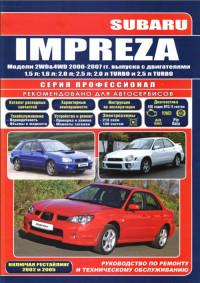
Руководство по эксплуатации, техническому обслуживанию и ремонту + каталог расходных запчастей автомобиля Subaru Impreza 2000-2007 годов выпуска с бензиновыми двигателями объемом 1,5/1,6/2,0/2,5 л.
- Автор: —
- Издательство: Легион-Автодата
- Год издания: 2014
- Страниц: 696
- Формат: —
- Размер: —
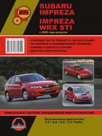
Руководство по эксплуатации и ремонту автомобилей Subaru Impreza и Subaru Impreza WRX STI с 2008 года выпуска с бензиновыми двигателями объемом 1,5/2,0/2,5 л.
- Автор: —
- Издательство: Монолит
- Год издания: —
- Страниц: 454
- Формат: —
- Размер: —
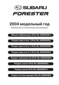
Руководство по техническому обслуживанию и ремонту автомобиля Subaru Impreza 2004 модельного года.
- Автор: —
- Издательство: Fuji Heavy Industries Ltd.
- Год издания: —
- Страниц: 3581
- Формат: PDF
- Размер: 96,7 Mb
Руководство по техническому обслуживанию и ремонту автомобиля Subaru Impreza 2008 модельного года.
- Автор: —
- Издательство: Fuji Heavy Industries Ltd.
- Год издания: —
- Страниц: 3744
- Формат: PDF
- Размер: 65,4 Mb
Руководство по эксплуатации и техническому обслуживанию автомобиля Subaru Impreza 2005 года выпуска.
- Автор: —
- Издательство: Fuji Heavy Industries Ltd.
- Год издания: 2004
- Страниц: 512
- Формат: PDF
- Размер: 10,0 Mb
Руководство по эксплуатации и техническому обслуживанию автомобиля Subaru Impreza 2007 года выпуска.
- Автор: —
- Издательство: Fuji Heavy Industries Ltd.
- Год издания: 2006
- Страниц: 464
- Формат: PDF
- Размер: 9,3 Mb
Руководство по эксплуатации и техническому обслуживанию автомобиля Subaru Impreza 2009 года выпуска.
- Автор: —
- Издательство: Fuji Heavy Industries Ltd.
- Год издания: 2008
- Страниц: 497
- Формат: PDF
- Размер: 7,7 Mb
Руководство по эксплуатации и техническому обслуживанию автомобией Subaru Impreza и Subaru XV 2012 года выпуска.
- Автор: —
- Издательство: Fuji Heavy Industries Ltd.
- Год издания: 2011
- Страниц: —
- Формат: PDF
- Размер: 184,2 Mb

Руководство по эксплуатации и техническому обслуживанию автомобиля Subaru Impreza 2000-2007 годов выпуска.
- Автор: —
- Издательство: MoToR
- Год издания: —
- Страниц: 512
- Формат: —
- Размер: —
Руководство по техническому обслуживанию и ремонту автомобиля Subaru Impreza 1993-2002 годов выпуска с бензиновыми двигателями объемом 1,5/1,6/1,8/2,0 л.
- Автор: —
- Издательство: Легион-Автодата
- Год издания: —
- Страниц: 656
- Формат: —
- Размер: —
Руководство по техническому обслуживанию и ремонту автомобилей Subaru Impreza/Impreza WRX/Impreza WRX STI с 2007 года выпуска с бензиновыми двигателями объемом 1,5/2,0/2,5 л.
- Автор: —
- Издательство: Легион-Автодата
- Год издания: 2012
- Страниц: 600
- Формат: —
- Размер: —

- Manuals
- Brands
- Subaru Manuals
- Automobile
- 2002 Impreza
- Owner’s manual
Subaru
-
Contents
-
Table of Contents
-
Bookmarks
Related Manuals for Subaru IMPREZA 2002
Summary of Contents for Subaru IMPREZA 2002
-
Page 1
2002 OWNER S MANUAL Always wear your seatbelt. -
Page 2
Foreword Congratulations on choosing a SUBARU vehicle. This Owner’s Manual has all the information necessary to keep your SUBARU in excellent condition and to properly maintain the emission control system for minimizing emission pollutants. We urge you to read this manual carefully so that you may understand your vehicle and its operation. -
Page 3
This manual describes the following vehicle types. HGF008AA Sedan HGF009AA Wagon and OUTBACK SPORT… -
Page 4
Booklet. Please read these warranties carefully. J Warranties for U.S.A. NOTE All SUBARU vehicles distributed by Subaru of Amer- ica, Inc. and sold at retail by an authorized SUBARU This vehicle does not contain mer- dealer in the United States come with the following warranties: cury devices or parts. -
Page 5
Chapter 8: Driving tips Each chapter begins with a brief table of contents, This chapter informs you how to drive your SUBARU so you can usually tell at a glance if that chapter in various conditions and explains some safety tips contains the information you want. -
Page 6: Safety Warnings
Please read these safety warnings as well as all oth- er portions of this manual carefully in order to gain a better understanding of how to use your SUBARU vehicle safely. HS0008…
-
Page 7: Child Safety
Safety precautions when driving the SRS airbag needs enough space for de- ployment, the driver should always sit upright J Seatbelt and SRS airbag and well back in the seat as far from the steer- ing wheel as practical while still maintaining full vehicle control and the front passenger WARNING should move the seat as far back as possible…
-
Page 8
and weight. If a child is too big for a child re- locks” section in chapter 2. D Always lock the passenger’s windows using straint system, the child should sit in the REAR seat and be restrained using the seat- the lock switch when children are riding in the belts. -
Page 9: Drinking And Driving
D If at any time you suspect that exhaust owner’s manual for instructions and precautions concerning the child restraint system, seatbelt sys- fumes are entering the vehicle, have the prob- tem and SRS airbag system. lem checked and corrected as soon as pos- sible.
-
Page 10
ently, you may have consumed too much alcohol to your doctor. drive safely even if the level of alcohol in your blood Never drive if you are under the influence of any illic- is below the legal limit. The safest thing you can do it mind-altering drugs. -
Page 11: Driving With Pets
J Modification of your vehicle J Driving with pets Unrestrained pets can interfere with your driving and distract your attention from driving. In a collision or CAUTION sudden stop, unrestrained pets or cages can be Your vehicle should not be modified. Modifica- thrown around inside the vehicle and hurt you or tion could affect its performance, safety or your passengers.
-
Page 12: California Proposition 65 Warning
WARNING Driving at high speeds with excessively low tire pressures can cause the tires to deform severely and to rapidly become hot. A sharp increase in temperature could cause tread separation, and destruction of the tires. The resulting loss of vehicle control could lead to an accident.
-
Page 14: Table Of Contents
Table of contents Seat, seatbelt and SRS airbags Keys and doors Instruments and controls Climate control Audio Interior equipment Starting and operating Driving tips In case of emergency Appearance care Maintenance and service Specifications Consumer information and Reporting safety defects Index –…
-
Page 15
Illustrated index J Exterior Engine hood (page 11-5) Headlight switch (page 3-15) Replacing bulbs (page 11-56) Wiper switch (page 3-21) Door locks (page 2-3) Tire pressure (page 11-38) Flat tires (page 9-5) Tire chains (page 8-14) Front fog light switch (page 3-19) 10) Tie-down eyes (page 9-15) 11) Towing eye (page 9-15) -
Page 16
Rear window defogger switch (page 3-24) Fuel filler lid and cap (page 7-4) Child safety locks (page 2-19) Towing eye (page 9-15) Trunk/Rear gate (page 2-23/2-27) HGF025BB – CONTINUED –… -
Page 17
J Interior B Passenger compartment area Lower anchorage for child restraint system (page 1-32) Seatbelt (page 1-11) Parking brake lever (page 7-25) Front seat (page 1-2) Rear seat (page 1-7) HBF030BB… -
Page 18
Cup holder (page 6-6) Center console (page 6-5) Glove compartment (page 6-5) Cigarette lighter (page 6-9) Ashtray (page 6-10) HGF031BB – CONTINUED –… -
Page 19
J Instrument panel Door locks (page 2-3) Light control lever (page 3-15) Combination meter (page 3-6) Wiper control lever (page 3-20) Hazard warning flasher switch (page 3-5) Audio (page 5-1) Gear shift lever (MT) (page 7-10)/Selector lever (AT) (page 7-13) Outside mirror switch (page 3-28) Climate control (page 4-1) -
Page 20
J Light control and wiper control levers/switches Parking light switch (page 3-19) Windshield wiper (page 3-20) Mist (page 3-21) Windshield washer (page 3-21) Rear window wiper and washer switch (page 3-23) Wiper control lever (page 3-21) Illumination brightness control (page 3-18) Light control lever (page 3-15) Headlight ON/OFF (page 3-15) 10) Headlight flasher High/Low… -
Page 21
J Combination meter B Overview Fuel gauge (page 3-7) Temperature gauge (page 3-8) Speedometer (page 3-6) Tachometer (page 3-7) Trip meter A/B selection and trip meter reset knob (page 3-6) Odometer and trip meter (page 3-6) Outside temperature indicator (page 3-9) Low fuel warning light (page 3-7) HGF026BB… -
Page 22
B Warning and indicator light Mark Name Page Mark Name Page Front-wheel drive warning Seatbelt warning light 3-14 light (if equipped) SRS airbag system warn- 3-10 Turn signal indicator lights 3-14 AIRBAG ing light CHECK ENGINE warning High beam indicator light 3-14 light/Malfunction indicator 3-10… -
Page 23
J Tire changing tools Jack (page 9-21) Jack handle (page 9-21) Spare tire (page 9-21) HGF035BB… -
Page 24
Seat, seatbelt and SRS airbags Front seats Top tether anchorages 1-35 …………… . SRS airbag Fore and aft adjustment . -
Page 25: Seat, Seatbelt And Srs Airbags
Seat, seatbelt and SRS airbags Front seats WARNING D Never adjust the seat while driving to avoid the possibility of loss of vehicle control and of personal injury. D Before adjusting the seat, make sure the hands and feet of rear seat passengers are clear of the adjusting mechanism.
-
Page 26: Fore And Aft Adjustment
Seat, seatbelt and SRS airbags J Fore and aft adjustment or in a seatbelt, whichever is appropriate for the child’s age, height and weight. Secure ALL types of child restraint devices (including for- ward facing child seat) in the REAR seats at all times.
-
Page 27: Reclining The Seatback
Seat, seatbelt and SRS airbags J Reclining the seatback WARNING To prevent the passenger from sliding under the seatbelt in the event of a collision, always put the seatback in the upright position while the vehicle is in motion. Also, do not place objects such as cushions between the pas- senger and the seatback.
-
Page 28: Seat Cushion Height Adjustment
Seat, seatbelt and SRS airbags J Seat cushion height adjustment J Head restraint adjustment (driver’s seat) To raise the head restraint, pull it up. The height of the seat can be adjusted by moving the seat cushion adjustment lever up and down. HB1016BA To lower it, push the head restraint down while HG1003BB…
-
Page 29: Seat Heater (If Equipped)
Seat, seatbelt and SRS airbags Seat heater (if equipped) HG1007BB 1) HI – Rapid heating 2) LO – Normal heating HG1004BA The indicator located on the switch comes on when The seat heater operates when the ignition switch is the seat heater is in operation. When the vehicle’s in- either in the “…
-
Page 30: Rear Seats
Seat, seatbelt and SRS airbags D Do not put anything on the seat which insu- Rear seats lates against heat, such as a blanket, cushion, or similar items. This may cause the seat heat- er to overheat. WARNING NOTE Seatbelts provide maximum restraint when D Use of the seat heater for a long period of time the occupant sits well back and upright in the seat.
-
Page 31: Armrest (If Equipped)
Seat, seatbelt and SRS airbags J Armrest (if equipped) WARNING D Never allow passengers to ride on the folded rear seatback or in the cargo area. Do- ing so may result in serious injury or death. D Never stack luggage or other cargo higher than the top of the seatback because it could tumble forward and injure passengers in the event of a sudden stop or accident.
-
Page 32: Folding Down The Rear Seat — Wagon
Seat, seatbelt and SRS airbags B Loading long objects operation of the car, possibly causing an acci- dent and serious injury. HG1029BA Folding down the armrest and opening the seatback HG1009BA panel affords a loading space for long objects. To open the seatback panel, pull the release tab. J Folding down the rear seat –…
-
Page 33: Headrest Adjustment (If Equipped)
Seat, seatbelt and SRS airbags D Secure skis and other lengthy items properly Unlock the seatback by pulling the release knob to prevent them from shooting forward and and then fold the seatback down. causing serious injury during a sudden stop. J Headrest adjustment (if equipped) HB1022BA HS1013CA…
-
Page 34: Seatbelts
Seat, seatbelt and SRS airbags pecially if they are 12 years of age and under Seatbelts and are not restrained or improperly re- J Seatbelt safety tips strained. Because children are lighter and weaker than adults, their risk of being injured WARNING from deployment is greater.
-
Page 35: Emergency Locking Retractor (Elr)
Seat, seatbelt and SRS airbags B Infants or small children and as low as possible over the hips, not over the waist. Use a child restraint system that is suitable for your vehicle. See information on “ Child restraint systems” J Emergency Locking Retractor (ELR) in this chapter.
-
Page 36: Seatbelt Warning Light And Chime
Seat, seatbelt and SRS airbags J Fastening the seatbelt When securing a child restraint system on the rear seats by the use of the seatbelt, the seatbelt must be changed over to the Automatic Locking Retractor WARNING (ALR) mode. D Never use a belt that is twisted or reversed. When the child restraint system is removed, make In an accident, this can increase the risk or sure that the seatbelt retracts fully and the retractor…
-
Page 37
Seat, seatbelt and SRS airbags B Front seatbelts can result in serious internal injury or death. D Never place the shoulder belt under the arm 1. Adjust the seat position: or behind the back. If an accident occurs, this Driver’s seat: Adjust the seatback to the upright can increase the risk or severity of injury. -
Page 38
Seat, seatbelt and SRS airbags n Adjusting the front seat shoulder belt anchor height The shoulder belt anchor height should be adjusted to the position best suited for you. To lower the an- chor height, push the release button and slide the anchor down. -
Page 39
Seat, seatbelt and SRS airbags bing in the door. WARNING B Rear seatbelts (except rear center seatbelt on When wearing the seatbelts, make sure the Wagon) shoulder portion of the webbing does not 1. Sit well back in the seat. pass over your neck. -
Page 40
Seat, seatbelt and SRS airbags 2) Place the lap belt as low as possible on your hips, not on your waist. HS1020BA Always adjust the anchor height so that the shoulder OM-H0044 belt passes over the middle of the shoulder without touching the neck. -
Page 41
Seat, seatbelt and SRS airbags n Unfastening the seatbelt plate into the mating buckle (on right-hand side), always check that the webbing is not Push the button on the buckle. twisted. HB0303 HB1030BA Before closing the door, make sure that the belts are retracted properly to avoid catching the belt web- bing in the door. -
Page 42
Seat, seatbelt and SRS airbags HG1012BA HG1023BA 1. Remove the tongue plate from the belt holder lo- cated under the right rear quarter glass and pull out the seatbelt slowly. HS1017BB 1) Center seatbelt tongue plate 2) Connector (tongue) HG1027BA 3) Connector (buckle) 4) Center seatbelt buckle –… -
Page 43
Seat, seatbelt and SRS airbags 2. After drawing out the seatbelt, pass it through the 4. Insert the center seatbelt tongue plate in the cen- belt guide as follows: First insert one edge of the ter seatbelt buckle marked “ CENTER” on the left- belt into the open gap in the comfort guide;… -
Page 44
Seat, seatbelt and SRS airbags 5. 1) To make the lap part tight, pull up on the n Unfastening the seatbelt shoulder belt. 2) Place the lap belt as low as possible on your hips, not on your waist. HS0317 Push the release button of the center seatbelt buckle (on the left-hand side) to unfasten the seat- HGS037BC… -
Page 45
Seat, seatbelt and SRS airbags disconnect from the buckle. HS1021BA HG1024BA 2. Allow the retractor to roll up the belt. You should hold the webbing end and guide it back into the re- tractor while it is rolling up. Insert the tongue plate into the belt holder. -
Page 46: Seatbelt Maintenance
Seat, seatbelt and SRS airbags trim during driving, causing damage to the CAUTION trim. D Keep the belts free of polishes, oils, chemi- cals and particularly battery acid. D Never attempt to make modifications or changes that will prevent the seatbelt from op- erating properly.
-
Page 47: Front Seatbelt Pretensioners
In the event that a preten- sioner is activated, both the driver’s and front passenger’s seatbelt retractor assemblies must be replaced only by an authorized SUBARU dealer. When replacing seatbelt retractor assem- blies, use only genuine SUBARU parts.
-
Page 48: System Monitors
Seat, seatbelt and SRS airbags J System monitors SUBARU dealer as soon as possible. D When you sell your vehicle, we urge you to explain to the buyer that it has seatbelt preten- sioners by alerting him to the contents of this section.
-
Page 49: System Servicing
SRS airbag nearest SUBARU dealer to have the system systems. For required servicing of the seat- checked. Unless checked and repaired, the seatbelt…
-
Page 50: Precautions Against Vehicle Modification
According to accident statistics, children are safer when properly restrained in the rear seating posi- tions than in the front seating positions. Always consult your SUBARU dealer if you want to install any accessory parts to your vehicle. – CONTINUED –…
-
Page 51
Seat, seatbelt and SRS airbags All U.S. states and Canadian provinces require that WARNING infants and small children be restrained in an approved child restraint system at all times while the Never let a passenger hold a child on his or vehicle is moving. -
Page 52
Seat, seatbelt and SRS airbags WARNING WARNING Children should be properly restrained at all Put children aged 12 and under in the rear times. Never allow a child to stand up, or to seat properly restrained at all times. The SRS kneel on any seat. -
Page 53
Seat, seatbelt and SRS airbags HS1031BA HS0042 WARNING WARNING D Child restraint systems and seatbelts can SINCE YOUR VEHICLE IS EQUIPPED WITH A PASSENGER’S AIRBAG, NEVER become hot in a vehicle that has been closed INSTALL A REARWARD FACING CHILD SAFE- up in sunny weather;… -
Page 54: Installing Child Restraint Systems With
Seat, seatbelt and SRS airbags J Installing child restraint systems with into the retractor. As the belt is rewinding, clicks will be heard which indicate the retractor functions as seatbelt ALR. 6. Before having a child sit in the child restraint sys- tem, move it back and forth to check if it is firmly secured.
-
Page 55: Installation Of Child Restraint Systems By
If you have any question concerning this type of of the seatbelts. Such child restraint systems are se- child restraint system, ask your SUBARU dealer. cured to the dedicated anchorages provided on the vehicle body.
-
Page 56
Seat, seatbelt and SRS airbags HB1090BA HG1030BA The lower anchorages (bars) are used for installing The tether anchorages (upper anchorages) are pro- a child restraint system only on the rear seat win- vided for all the seating positions (middle and both dow-side seating positions. -
Page 57
If you have any question concerning this type of child restraint system, ask your SUBARU dealer. HB1088BA Each lower anchorage is located where the seat WARNING cushion meets the seatback. -
Page 58: Top Tether Anchorages
Seat, seatbelt and SRS airbags J Top tether anchorages B Anchorage location HG1031BB 1) For left seat HG1032BB 2) For center seat 3) For right seat 1) For left seat Sedan: Three anchorages are installed on the rear 2) For center seat 3) For right seat parcel shelf.
-
Page 59
Seat, seatbelt and SRS airbags Wagon: There is an anchorage for the center seat- n Wagon ing position at the rear end of the ceiling, and anchorages for each of the two window-side seating positions on the rear wall of the cargo area. B To hook the top tether n Sedan HGS031BA… -
Page 60
Seat, seatbelt and SRS airbags HGS032BB HGS033BB Center Window-side F: Front of vehicle F: Front of vehicle 1) Top tether hook 1) Top tether hook 2) Upper anchorage 2) Upper anchorage 2. Fasten the top tether hook of the child restraint system to the appropriate upper anchorage. -
Page 61: Srs Airbag
Seat, seatbelt and SRS airbags *SRS airbag (Supplemental Restraint protection provided by the seatbelt. It does not do away with the need to fasten seatbelts. System airbag) In combination with the seatbelts, it offers the best combined protection in case of a serious *SRS: This stands for supplemental restraint system.
-
Page 62
Seat, seatbelt and SRS airbags deployment force. D The SRS airbags deploy with considerable speed and force. Occupants who are out of proper position when the SRS airbag deploys could suffer very serious injuries. Because the SRS airbag needs enough space for de- ployment, the driver should always sit upright and well back in the seat as far from the steer- ing wheel as practical while still maintaining… -
Page 63
Seat, seatbelt and SRS airbags strained at all times in a child restraint device CAUTION or in a seatbelt, whichever is appropriate for D When the SRS airbag deploys, some smoke the child’s age, height and weight. Secure ALL types of child restraint devices will be released. -
Page 64
Seat, seatbelt and SRS airbags Airbag control module (including impact sensors) Airbag module (driver’s side) Airbag module (passenger’s side) Front sub sensor (left hand side) Front sub sensor (right hand side) Side airbag module (driver’s side — if equipped) Side airbag module (passenger’s side —… -
Page 65: Srs Frontal Airbag
Seat, seatbelt and SRS airbags J SRS frontal airbag WARNING Never allow a child to stand up, or to kneel on WARNING the front passenger’s seat, or never hold a child on your lap or in your arms. The SRS air- NEVER INSTALL A REARWARD FACING bag deploys with considerable force and can…
-
Page 66
Seat, seatbelt and SRS airbags SRS airbag contacts an occupant not in prop- er position such as one thrown toward the front of the car during pre-accident braking. HG1013BA WARNING HG1001BA The SRS airbag deploys with considerable speed and force. Occupants who are out of The driver’s SRS frontal airbag is stowed in the cen- proper position when the SRS airbag deploys ter portion of the steering wheel. -
Page 67
Seat, seatbelt and SRS airbags WARNING WARNING Do not put any objects over the steering Do not attach accessories to the windshield, wheel pad and dashboard. If the SRS frontal or fit an extra-wide mirror over the rear view airbag deploys, those objects could interfere mirror. -
Page 68
Seat, seatbelt and SRS airbags B Operation The front passenger’s SRS frontal airbag deploys to- gether with driver’s SRS frontal airbag even when no The SRS airbag can function only when the ignition one occupies the front passenger’s seat. switch is in the “ ON” position. Although it is highly unlikely that the SRS airbag If the front sub sensors inside the both front fenders would activate in a non-accident situation, should it… -
Page 69
Seat, seatbelt and SRS airbags HS2001BB 1-46… -
Page 70
Seat, seatbelt and SRS airbags When the SRS airbag deploys, a sudden, fairly loud force experienced in the passenger compartment inflation noise will be heard and some smoke will be during a collision. That level differs from one type of released. -
Page 71
Seat, seatbelt and SRS airbags n At what other times might the SRS frontal air- The SRS frontal airbag may be activated when the bag deploy? vehicle sustains a hard impact in the undercarriage area from the road surface (such as when the ve- hicle plunges into a deep ditch, is severely bumped or knocked hard against an obstacle on the road such as a curb). -
Page 72
Seat, seatbelt and SRS airbags n When is the SRS frontal airbag unlikely to There are many types of collisions which might not deploy? necessarily require SRS frontal airbag deployment. If the vehicle strikes an object, such as a telephone pole or sign pole, or if it slides under a truck’s load bed, or if it sustains an oblique offset frontal impact, the SRS frontal airbag may not deploy depending on… -
Page 73
Seat, seatbelt and SRS airbags n When will the SRS frontal airbag not deploy? The SRS frontal airbag is basically not designed to deploy if the vehicle is struck from side or from behind, or if it rolls onto its side or roof, or if it is in- volved in a low-speed frontal collision. -
Page 74: Srs Side Airbag (If Equipped)
Seat, seatbelt and SRS airbags J SRS side airbag (if equipped) WARNING D The SRS side airbag is designed as only a supplement to the primary protection pro- vided by the seatbelt. It does not do away with the need to fasten seatbelts. It is also impor- tant to wear your seatbelt to help avoid inju- ries that can result when an occupant is not seated in a proper upright position.
-
Page 75
Seat, seatbelt and SRS airbags HS0351 HB0354 WARNING Never allow a child to kneel on the front pas- senger’s seat facing the side window or to wrap his/her arms around the front seatback. In the event of an accident, the force of the SRS side airbag deployment could injure the child seriously because his/her head or arms or other body parts are too close to the SRS… -
Page 76
Seat, seatbelt and SRS airbags WARNING WARNING Do not attach accessories to the door trim or Do not put any kind of cover or clothes or oth- near either SRS side airbags and do not place er objects over either front seatback and do objects near the SRS side airbags. -
Page 77
Seat, seatbelt and SRS airbags B Operation deploys between the occupant and the door panel and supplements the seatbelt by reducing the im- The SRS side airbag can function only when the pact on the occupant’s chest. ignition switch is in the “ ON” position. The driver’s and front passenger’s SRS side airbags deploy independently of each other since each has its own impact sensor. -
Page 78
Seat, seatbelt and SRS airbags The SRS side airbag deploys even when no one oc- cupies the seat on the side on which an impact is applied. When the SRS side airbag deploys, a sudden, fairly loud inflation noise will be heard and some smoke will be released. -
Page 79
Seat, seatbelt and SRS airbags of force experienced in the passenger compartment n When is the SRS side airbag unlikely to during a side impact collision. That level differs from deploy? one type of collision to another, and it may have no There are many types of collisions which might not bearing on the visible damage done to the vehicle necessarily require SRS side airbag deployment. -
Page 80
Seat, seatbelt and SRS airbags 1) The vehicle is involved in an oblique side-on impact. 2) The vehicle is involved in a side-on impact in an area outside the pas- senger compartment. 3) The vehicle strikes a telephone pole or similar object. 4) The vehicle is involved in a side-on impact from a motorcycle. -
Page 81
Seat, seatbelt and SRS airbags n When will the SRS side airbag not deploy? The SRS side airbag is basically not designed to deploy if the vehicle is involved in a frontal collision or is struck from behind. Examples of such acci- dents are illustrated. -
Page 82: Srs Airbag System Monitors
D All related wiring In the event of a malfunction indicated by any of fol- lowing, the vehicle should be taken promptly to your nearest SUBARU dealer to have the system checked. Unless checked and repaired, the SRS airbags will not function reliably: D Flashing or flickering of the indicator light.
-
Page 83: Srs Airbag System Servicing
SUBARU parts. To ensure their long-term reliability, the SRS airbags must be inspected by a SUBARU dealer ten years after the date of manufacture, which is shown on the certification plate attached to the driver’s door jamb.
-
Page 84: Precautions Against Vehicle Modification
Seat, seatbelt and SRS airbags J Precautions against vehicle modifica- NOTE In the following cases, contact your SUBARU tion dealer as soon as possible. D The front part of the vehicle was involved in an WARNING accident in which the SRS frontal airbags did not deploy.
-
Page 85
D Attachment of any equipment (side steps or side sill protectors, etc.) other than SUBARU genuine accessory parts to the side body (for vehicles with side airbags only). Always consult your SUBARU dealer if you want to install any accessory parts to your vehicle. 1-62… -
Page 86
Keys and doors Keys To cancel the trunk lid release 2-24 …………… Trunk lid release handle 2-25 Key number… -
Page 87: Keys And Doors
Keys and doors Keys locks. You can keep the trunk and glove compart- ment locked when you leave your vehicle and valet key at a parking facility. J Key number The key number is stamped on the metal plate attached to the key set. Write down the key number and keep it in another safe place, not in the vehicle.
-
Page 88: Door Locks
Keys and doors Door locks J Locking and unlocking from the out- side HB2024BC 1) Rotate the lock lever rearward. 2) Close the door. To lock the door from the outside without the key, rotate the lock lever rearward and then close the HS0010 door.
-
Page 89
Keys and doors NOTE Pull the inside door handle to open an unlocked door. Make sure that you do not leave the key inside the vehicle when locking the doors from the out- Always make sure that all doors and the rear gate side without the key. -
Page 90: Power Door Locking Switches (If Equipped)
Keys and doors Power door locking switches NOTE Make sure that you do not leave the key inside (if equipped) the vehicle before locking the doors from the outside using power door locking switches. HG2012BB 1) Lock 2) Unlock All doors and the rear gate (wagon) can be locked and unlocked by the power door locking switches located at the driver’s side and the front passenger’s side doors.
-
Page 91: Keyless Entry System (If Equipped)
Keys and doors Keyless entry system (if equipped) The operable distance of the keyless entry system is approximately 30 feet (10 meters). However, this distance will vary depending on environmental Two transmitters are provided for your vehicle. conditions. Range may be reduced near sources of The keyless entry system has the following func- RF interference such as power plants and radio/tele- tions.
-
Page 92: Sounding A Panic Alarm
Keys and doors that the doors (or the rear gate) are not properly closed. When you close the door, it will automatically lock. J Unlocking the doors Briefly press the “ UNLOCK/DISARM” button (for less than two seconds) to unlock the driver’s door. The horn will sound two times.
-
Page 93: Selecting Audible Signal Operation
Keys and doors “ UNLOCK/DISARM” button. Unless a button on the To replace the battery: remote is pressed, the alarm will be deactivated after approximately 30 seconds. J Selecting audible signal operation Using the horn, the system will give you an audible signal when the doors lock and unlock.
-
Page 94: Replacing Lost Transmitters
Keys and doors CAUTION Do not let dust, oil or water get on or in the transmitter when replacing the battery. J Replacing lost transmitters If you lose a transmitter or want to purchase addi- tional transmitters (up to four can be programmed), you should re-program all of your transmitters for security reasons.
-
Page 95
Keys and doors To enter the programming mode: HB1005BC HB1000CA 2. Open the driver’s door and sit in the driver’s seat. 3. Close the driver’s door. 1. Press “ UNLOCK/DISARM” button to disarm the security system. (If your vehicle is equipped with the optional security system.) HB2032BC 1) ON… -
Page 96
Keys and doors 4. Place the ignition key into the ignition switch and cycle the switch from LOCK to ON ten times within 15 seconds. Be sure to stop at the LOCK position. The horn will sound once to indicate that you are in the transmitter programming mode. -
Page 97: System Operation
Keys and doors operates by operating each transmitter. Security system (if equipped) B Deleting old transmitter codes The security system helps to protect your vehicle The control unit of the keyless entry system has four and valuables from theft. The horn sounds and the memory locations to store transmitter codes, giving parking lights flash if someone attempts to break it the ability to operate with up to four transmitters.
-
Page 98: Arming The System
Keys and doors breaking glass or forced entry). Note that there are two alarm levels for shock: warning and alarm. In warning mode, the alarm detects lower level vibra- tions and triggers 2 warning chirps on the horn and two flashes on the lights as a deterrent to would be vandals.
-
Page 99
Keys and doors 6. Briefly press the “ LOCK/ARM” button (for less than two seconds). All doors (and the rear gate on the wagon) will lock, the horn will sound one time, the parking lights will flash one time and the indica- tor light starts flashing slowly (approximately once every two seconds). -
Page 100: Sounding A Panic Alarm
Keys and doors J Disarming the system To deactivate it, press the “ LOCK/ARM” button or “ UNLOCK/DISARM” button. Briefly press the “ UNLOCK/DISARM” button (for less The parking lights will also flash when the alarm is than two seconds) on the remote transmitter. The activated.
-
Page 101
Keys and doors Note that in this mode, DOORS MUST BE MANUAL- LY LOCKED. B To enter the passive mode HB2038BC 1) Connector for SRS airbag system (yel- low) 2) Blue (1P) HB2036BA 2. Connect the blue (1 pole) connector. 1. -
Page 102
Keys and doors 2. Turn the ignition switch from “ ON” to “ LOCK” WARNING position and remove the key from the ignition switch. Do not disconnect or tamper with any yellow connector and/or any harness covered with yellow insulation and/or tape. Doing so could result in accidental inflation of the SRS airbag or could make the SRS airbag system inoperative, which may result in seri-… -
Page 103
Keys and doors The indicator light provides the following indications. CAUTION Flashing one time: Any door, the rear gate or the trunk lid has been opened. In passive mode, the system will automatically Flashing three times: The impact sensor in the sys- activate the alarm but WILL NOT automatically tem’s unit has been activated. -
Page 104: Child Safety Locks
Keys and doors Child safety locks WARNING Always use the child safety lock whenever a Each rear door has a child safety lock that prevents child rides in the rear seat. Serious injury the doors from being opened even if the inside door could result if a child accidentally opened the handle is pulled.
-
Page 105: Windows
Keys and doors B Driver’s side switches Windows J Power windows WARNING D When operating the power windows, be ex- tremely careful to prevent anyone’s fingers, arms or head from being caught in the win- dow. D Always lock the passengers’ windows using the lock switch when children are riding in the HG2016BB vehicle.
-
Page 106
Keys and doors n Operating the driver’s window n Operating the passengers’ windows HG2008DB HG2008CA 1) Open To open the passengers’ windows, push the ap- 2) Automatically open propriate switch down and hold it until the window 3) Close reaches the desired position. To close the window, pull the switch up and hold it until it reaches the de- AUTO switch: This switch has two functions. -
Page 107
Keys and doors n Locking the passengers’ windows “ LOCK” position, the passengers’ windows cannot be operated with the passengers’ switches. HG2013BB 1) Lock 2) Unlock To lock the passengers’ windows, push the lock switch. When the lock switch is in the “ LOCK” posi- tion, the passengers’… -
Page 108: Trunk Lid (Sedan)
Keys and doors J To open and close the trunk lid from Trunk lid (Sedan) outside WARNING D To prevent dangerous exhaust gas from en- tering the vehicle, always keep the trunk lid closed while driving. D Help prevent young children from locking themselves in the trunk.
-
Page 109: To Open The Trunk Lid From Inside
Keys and doors J To open the trunk lid from inside J To cancel the trunk lid release HB3000CC HG2009BA 1) Open The inside trunk lid release can be cancelled to help prevent unauthorized entry into the trunk. To cancel Pull the trunk lid release lever upward.
-
Page 110: Trunk Lid Release Handle
Keys and doors J Trunk lid release handle short time. The trunk lid release handle is a device designed to WARNING open the trunk lid from inside the trunk. In the event children or adults become locked inside the trunk, Never allow any child to get in the trunk and the handle allows them to open the lid.
-
Page 111
Keys and doors B Inspection Perform the following steps at least twice a year to check the release handle for correct operation. 1. Open the trunk lid. 2. Use a screwdriver with a thin blade. Slide the screwdriver blade from the slit aperture of the lock assembly fully to the end until you hear a click. -
Page 112: Rear Gate (Wagon)
Keys and doors If the latch is not released, contact your SUBARU Rear gate (Wagon) dealer. In that case, use the key to release the latch, then close the trunk lid. Also, if the movements of the release handle feel re-…
-
Page 113
Keys and doors latch engages. WARNING To prevent dangerous exhaust gas from enter- ing the vehicle, always keep the rear gate closed while driving. 2-28… -
Page 114
Instruments and controls Ignition switch Front-wheel drive warning light ……..(for AT vehicles –… -
Page 115: Instruments And Controls
Instruments and controls B Automatic transmission vehicles Ignition switch HB4016BA HB3014BA The ignition switch has four positions: LOCK, ACC, ON and START. J LOCK The key can only be inserted or removed in this position. The ignition switch will lock the steering wheel when you remove the key.
-
Page 116: Acc
Instruments and controls J ACC when the selector lever is in the “ P” position. B Manual transmission vehicles In this position the electrical accessories (radio, cig- arette lighter, etc.) can be used. J ON This is the normal operating position after the engine is started.
-
Page 117
Instruments and controls J Key interlock release (AT vehicles only) If the key can not be turned to the “ LOCK” position even when the selector lever is in the “ P” position: 1. Take out the screwdriver from the tool bag. HB3012BA HB3011BA 2. -
Page 118: Hazard Warning Flasher
Instruments and controls Hazard warning flasher Take your vehicle to the nearest SUBARU dealer im- mediately to have the key interlock system repaired. HG3004AA The hazard warning flasher is used to warn other drivers when you have to park your vehicle under emergency conditions.
-
Page 119: Meters And Gauges
Instruments and controls B Double trip meter Meters and gauges J Speedometer The speedometer shows the vehicle speed. J Odometer/Trip meter HG3006BB 1) A trip meter 2) B trip meter The trip meter shows the distance that the vehicle has been driven since you last set it to zero. To change the mode indication, briefly push the HG3005BB knob.
-
Page 120: Fuel Gauge
Instruments and controls J Fuel gauge CAUTION To ensure safety, do not attempt to change the function of the indicator during driving, as an accident could result. NOTE If the connection between the combination meter and battery is broken for any reason such as ve- hicle maintenance or fuse replacement, the data recorded on the trip meter will be lost.
-
Page 121: Fuel Gauge
Instruments and controls NOTE about 4.0 U.S. gal. (15 liters, 3.3 Imp. gal.). J Temperature gauge HG3016AA You will see the “ FUEL DOOR p” sign near the HG3008BB fuel gauge. This indicates that the fuel filter door (lid) is 1) Normal operating range located on the right side of the vehicle.
-
Page 122: (If Equipped)
D When there is too much sun. bulb or a malfunction of the corresponding system. D During idling; while running at low speeds in a Consult your authorized SUBARU dealer for repair. traffic jam; when the engine is restarted immediately following a shutdown.
-
Page 123: Check Engine Warning Light
If the CHECK ENGINE light comes on while you are driving, have your vehicle checked/re- J SRS airbag system warning paired by your SUBARU dealer as soon as light AIRBAG possible. Continued vehicle operation without having the emission control system checked When the ignition switch is turned to the “…
-
Page 124: Charge Warning Light
If the light does not go after the engine starts, stop the engine at the first out, take your vehicle to your authorized SUBARU safe opportunity and check the alternator belt. If the dealer immediately.
-
Page 125: At Oil Temperature Warning
If these occur, have the ABS system repaired is not working properly. Contact your nearest at the first available opportunity by your SUBARU dealer for service immediately. SUBARU dealer. (U.S.) J ABS warning light…
-
Page 126: Door Open Warning Lights
The door open warning light comes on if any door or by a SUBARU dealer immediately. the rear gate is not fully closed. D If at all in doubt about whether the brakes –…
-
Page 127: Turn Signal Indicator Lights
Instruments and controls Always make sure this light is out before you start to Clock drive. J Front-wheel drive warning light (for AT vehicles – if equipped) This light comes on when All Wheel Drive is disen- gaged and the drive mechanism is switched to Front Wheel Drive for maintenance or similar purposes.
-
Page 128: Light Control Switch
Instruments and controls J Headlights Light control switch The light switch operates only when the ignition switch is in the “ ON” position. WARNING To prevent battery discharge resulting from accidentally leaving your lights on when your vehicle is parked, the light switch operates only when the ignition switch is in the “…
-
Page 129: Headlight Flasher
Instruments and controls J High/low beam change (dimmer) J Headlight flasher HG3014CA HG3014BA To change from low beam to high beam, push the To flash the headlights, pull the lever toward you and turn signal lever forward. When the headlights are then release it.
-
Page 130: Turn Signal Lever
Instruments and controls J Daytime running light system Turn signal lever WARNING The tail lights, parking lights, and side marker lights are not turned on by the daytime run- ning light system. The light switch must al- ways be turned to the “ a” position when it is dark outside.
-
Page 131: Illumination Brightness Control
Instruments and controls the direction of the turn or lane change. The lever Illumination brightness control will return automatically to the neutral position when you release it. When the lighting switch is in the “ p” or “ a” position, you can adjust brightness of the instrument panel illumination for better visibility.
-
Page 132: Parking Light Switch
Instruments and controls Parking light switch Fog light switch (if equipped) The fog lights operate only when the headlights are on low beam. Push the fog light switch to turn the fog lights on. Press the switch again to turn them off. HB2018BA The parking light switch operates regardless of the ignition switch position.
-
Page 133: Wiper And Washer
In areas where water freezes in D Do not operate the wipers when the wind- winter, use SUBARU Windshield Washer Fluid shield or rear window is dry. This may scratch or the equivalent. (See the “ Windshield wash- the glass, damage the wiper blades and cause er fluid”…
-
Page 134: Windshield Wiper And Washer
Instruments and controls This will cause deterioration of the wiper blades with new ones. Refer to the “ Wiper blade blades. replacement” section (chapter 11) for replace- ment instructions. NOTE J Windshield wiper and washer D The wiper operates only when the ignition switch is in the “…
-
Page 135
Instruments and controls B Mist (for a single wipe) To turn the wipers off, return the lever to the “ OFF” position. B Wiper intermittent time control (if equipped) HG3011BA For a single wipe of the wipers, pull the lever toward HB2023BA you. -
Page 136: Rear Window Wiper And Washer
Instruments and controls J Rear window wiper and washer B Washer switch (if equipped) HB2020BA HB2021BB To wash the windshield, push the washer button at the end of the wiper control lever. The washer fluid 1) Rear wiper 2) Washer sprays until you release the washer button.
-
Page 137: Rear Window Defogger Switch
Instruments and controls washer fluid sprays until you release the knob. Rear window defogger switch To wash the rear window when the rear wiper is not in use, turn the knob on the end of the wiper control The rear window defogger operates only when the lever clockwise to the “…
-
Page 138: Mirrors
Instruments and controls To turn on the defogger, push the switch. To turn it Mirrors off, push the switch again. The indicator light located on the switch lights up Always check that the inside and outside mirrors are while the rear window defogger is operating. properly adjusted before you start driving.
-
Page 139
Instruments and controls B Compass mirror (if equipped) D By pressing and releasing the right button, the compass display is toggled on or off. When the compass is on, an illuminated compass reading will appear in the lower part of the mirror. Even with the mirror in anti-glare mode, the mirror surface turns bright if the transmission is shifted into reverse. -
Page 140
Instruments and controls blinded. For this reason, use care not to cover the n Compass zone adjustment sensors with stickers, or other similar items. Periodi- cally wipe the sensors clean using a piece of dry soft cotton cloth or an applicator. n Compass calibration 1. -
Page 141: Outside Mirrors
Instruments and controls 4. Releasing the button for 3 seconds will exit the tance of objects that you view in convex mir- zone setting mode. ror. J Outside mirrors B Remote control mirror switch The remote control mirrors operate only when the ignition switch is in the “…
-
Page 142
Instruments and controls The mirrors can also be adjusted manually. 15 minutes. If the mirror clears before that time, push the switch to turn it off. It also turns off when B Outside mirror defogger (if equipped) the ignition switch is turned to the “ ACC” or “ LOCK” The outside mirror defogger shares the switch with position. -
Page 143: Tilt Steering Wheel
Instruments and controls Tilt steering wheel WARNING Do not adjust the steering wheel tilt position while driving. This may cause loss of vehicle control and result in personal injury. HB4002BA 1. Adjust the seat position. Refer to the “ Front seat” section (chapter 1).
-
Page 144: Horn
Instruments and controls Horn OM-H0440 To sound the horn, push the horn pad. – CONTINUED – 3-31…
-
Page 146: Climate Control
Climate control Ventilator ……….Air flow selection .
-
Page 147: Climate Control
Climate control Ventilator J Air flow selection HG4003BA…
-
Page 148: Center And Side Ventilators
Climate control J Center and side ventilators B Side ventilators B Center ventilators HG4031BB 1) Open 2) Close HG4030BA Move the knob in any direction you prefer to adjust Move the tab up and down or right and left to adjust the flow direction.
-
Page 149: Climate Control System
Climate control Climate control system to red side (warm). B Fan speed control dial J Control panel The fan operates only when the ignition switch is turned to the “ ON” position. The fan speed control dial is used to select four fan speeds. B Air flow control dial This dial has the following five positions: : Air flows through the instrument panel out-…
-
Page 150: Heater Operation
Climate control B Air conditioner button (if equipped) WARNING Continued operation in the position may fog up the windows. Switch to the posi- tion as soon as the outside dusty condition clears. J Heater operation B Defrosting or defogging the windshield HB5010BB 1) Push The air conditioner operates only when the engine is…
-
Page 151
Climate control 2. Set the air flow control dial to the “ ” position. To direct warm air toward the floor and the wind- 3. Turn the temperature control dial all the way to shield: the right. 1. Set the air inlet selection lever to the “ ”… -
Page 152
Climate control To direct warm air toward the floor: This setting allows you to direct air of different tem- 1. Set the air inlet selection lever to the “ ” peratures from the instrument panel and foot outlets. position The air from the foot outlets is slightly warmer than 2. -
Page 153: Air Conditioner Operation
Climate control B Ventilation WARNING Continued operation in the “ ” position may fog up the windows. Switch to the “ ” position as soon as the outside dusty condition clears. J Air conditioner operation B Cooling or dehumidifying HG4027AA To force outside air through the instrument panel outlets: 1.
-
Page 154
Climate control 1. Set the air inlet selection lever to the “ ” posi- tion. tion. 3. Set the air conditioner button to the “ ON” posi- 2. Set the air flow control dial to the “ ” position. tion. 3. -
Page 155: Cleaning Ventilator Grille
This check is best performed by your SUBARU paired by any accumulation of insects and leaves dealer.
-
Page 156
Your air conditioner uses ozone friendly refrigerant HFC134a. Therefore, the method of adding, chang- ing or checking the refrigerant is different from the method for CFC12 (Freon). Consult your SUBARU dealer for service. Repairs needed as a result of – CONTINUED –… -
Page 157: Air Filtration System (If Equipped)
Since the filter element is a viscous type, it is unnecessary to clean or wash the element. Have your filter checked or replaced by your SUBARU dealer. Replacement schedule: Every 12 months or 7,500 miles (12,000 km) whichever comes first…
-
Page 158: Audio
Audio Antenna system ……..FM reception .
-
Page 159: Antenna System
Audio Antenna system Installation of accessories Always consult your SUBARU dealer before instal- ling a citizen band radio or other transmitting device in your vehicle. Such devices may cause the elec- tronic control system to malfunction if they are incor- rectly installed or if they are not suited for the ve- hicle.
-
Page 160: Type B Audio Set
Audio J Type B audio set Audio set Your SUBARU may be equipped with one of the fol- lowing audio sets. See the pages indicated in this section for operating details. J Type A audio set HS5004AA D Radio operation: refer to page 5-14…
-
Page 161: Radio Operation
Audio Type A audio set (if equipped) The radio will operate only when the ignition switch is in the “ ACC” or “ ON” position. J Radio operation (1) SCAN button (2) Power switch, Volume control, Bass/Middle/Treble control and Fader/Balance control dial (3) Tuning buttons (4) FM/AM selection button (5) Preset buttons…
-
Page 162
Audio B Power switch and volume/bass/treble/fader/ To change control modes: Each brief press of the balance control (PWR/VOL) “ T/B” button changes control modes in the following sequence starting from volume control mode. (When The dial (2) is used for both power (ON/OFF) and the radio is first turned on, the control mode is in the volume control. -
Page 163
Audio Display Control mode HB5036BA Turn counterclockwise Turn clockwise Bass control For less bass For more bass Treble control For less treble For more treble Balance con- To increase left speaker volume and decrease To increase right speaker volume and trol right speaker volume decrease left speaker volume… -
Page 164
Audio from the low end to the high end. Press the “ SCAN” button again to cancel the SCAN mode and to stop on any displayed frequency. When the “ SCAN” button is pressed for automatic tuning, stations are scanned in the direction of low The display indicates which one is currently frequencies to high frequencies only. -
Page 165: Compact Disc Player Operation
Audio NOTE preset buttons are cleared. If this occurs, it is necessary to reset the preset buttons. If the connection between the radio and battery is broken for any reason such as vehicle mainte- nance or radio removal, all stations stored in the J Compact disc player operation (7) Eject button (8) Disc slot…
-
Page 166
Audio B To play back a compact disc B To select a song from its beginning n When CD is not in the player n Forward direction ∧ Hold a disc with a finger in the center hole while Briefly press the “ ”… -
Page 167
An optional CD changer can be connected to this B Random playback audio unit. See your SUBARU dealer for more information. Press the “ RPT/RDM” button (10) and hold it in for more than 2 seconds while a disc is being played back to play all songs on the disc in a random order. -
Page 168
Audio (12) Track selection buttons (13) DISC button (14) Repeat/Randam button (15) Disc selection button HG5008DB – CONTINUED – 5-11… -
Page 169
Audio B To start playback azines can also be selected in a similar way. When the “ CD” button (13) is pressed, the CD NOTE changer will start playback. The display shows the D No disc change takes place if the button corre- current disc number, track number and the elapsed sponding to the magazine slot in which no disc time during playback. -
Page 170
Audio the CD changer will automatically stop fast forward- To cancel the random mode, press the button again. ing and start playback beginning with the first track Then the “ RDM” indicator goes out, and normal on the current disc. playback mode is restored. -
Page 171
Audio Type B audio set (if equipped) The radio will operate only when the ignition switch is in the “ ACC” or “ ON” position. J Radio operation (1) FM button (2) AM button (3) SCAN button (4) Tuning knob (5) Preset buttons (6) Fader/Balance selection button (7) Power switch, Volume control,… -
Page 172
Audio B Power switch and volume/bass/treble/fader/ This dial is used for bass/treble controls when the balance control (PWR/VOL) “ BAS/TRE” button (8) is in the depressed position. It The dial (7) is used for both power (ON/OFF) and is also used for fader/balance controls when the volume control. -
Page 173
Audio n Tone control To change control modes: Each brief press of the “ FAD/BAL” button (6) changes control modes in the The volume control dial (7) normally function as vol- following sequence starting from fader control ume control. The dial become a control for Bass or mode. -
Page 174
Audio B Manual tuning (TUNE) n Seek tuning Turn the tuning knob (4) and hold it for more than a half second. Seek tuning will operate and stop auto- matically on the next station. Continue this operation until you find the desired station. -
Page 175
Audio B How to preset stations 1. Press the “ FM/AM” selection button to select AM, FM1 or FM2 reception. 2. Press the “ SCAN” button (3) or tune the radio manually until the desired station frequency is dis- played. 3. -
Page 176: Cassette Player Operation
Audio J Cassette player operation (9) Cassette slot (10) Eject button (11) Repeat button (12) TAPE (cassette player selection) button (13) TPS button (14) Dolby B NR button (15) Fast forward button (16) Program switching button (17) Rewind button HS5004CB –…
-
Page 177
Audio NOTE B Program switching button (PROG) D Only use good quality cassettes (cassettes When the program switching button “ PROG” (16) is longer than C-90 are not recommended). pressed during playback, the tape travel indicators D Put cassettes back in their boxes immediately will switch and the player will begin playing back the after use to protect them from dust and dirt and opposite side of the tape. -
Page 178
Audio B Tape program sensor button (TPS) D When the blanks between selections are shorter than five seconds. n Blank skip D When there are no blanks between selections (live When the “ TPS” button (13) is pressed, the “ TPS” in- concerts, etc.). -
Page 179: Built In Cd Changer Operation
Audio B Dolby B NR button ( Dolby Laboratories Licensing Corporation. “ Dolby” and the double-D Symbol are trade marks of Dolby Laboratories Li- Press “ ” button (14) when playing tapes re- censing Corporation. corded using the Dolby NR system*. The “ ”…
-
Page 180
Audio D The disc indicator steadily lights up if a disc is al- NOTE ready inserted in the corresponding position of the Make sure to always insert a disc with the label magazine. side up. If a disc is inserted with the label side D While the player is in the loading mode, if you down, it might be ejected or the player might press any of the other mode buttons “… -
Page 181
Audio press any of the other mode buttons “ FM” (2), “ AM” When a CD is loaded, the player will start playback (1) and “ TAPE” (12), the player will enter standby of the CD, beginning with the first number. mode. -
Page 182
Audio n Skipping forward To cancel the repeat mode, press the button again. Then the “ RPT” indicator goes out, and normal play- Turn the “ TRACK” knob (24) clockwise and release it back mode is restored. immediately to skip to the beginning of the next track. -
Page 183
Audio whose “ DISC” indicator is ON. Precautions to observe when han- 2. Press the “ EJECT” button (22). Then the “ DISC” dling a compact disc (CD) indicator associated with the disc you have selected will blink, and the disc will be ejected. D To remove a disc from the case, press the center To remove more discs in succession, repeat Steps 1 of the case and hold both edges of the disc. -
Page 184
Audio HG5009BA – CONTINUED – 5-27… -
Page 186
Audio Antenna system ……..FM reception . -
Page 187
Audio Antenna system Installation of accessories Always consult your SUBARU dealer before instal- ling a citizen band radio or other transmitting device in your vehicle. Such devices may cause the elec- tronic control system to malfunction if they are incor- rectly installed or if they are not suited for the ve- hicle. -
Page 188
Audio J Type B audio set Audio set Your SUBARU may be equipped with one of the fol- lowing audio sets. See the pages indicated in this section for operating details. J Type A audio set HS5004AA D Radio operation: refer to page 5-14… -
Page 189
Audio Type A audio set (if equipped) The radio will operate only when the ignition switch is in the “ ACC” or “ ON” position. J Radio operation (1) SCAN button (2) Power switch, Volume control, Bass/Middle/Treble control and Fader/Balance control dial (3) Tuning buttons (4) FM/AM selection button (5) Preset buttons… -
Page 190
Audio B Power switch and volume/bass/treble/fader/ To change control modes: Each brief press of the balance control (PWR/VOL) “ T/B” button changes control modes in the following sequence starting from volume control mode. (When The dial (2) is used for both power (ON/OFF) and the radio is first turned on, the control mode is in the volume control. -
Page 191
Audio Display Control mode HB5036BA Turn counterclockwise Turn clockwise Bass control For less bass For more bass Treble control For less treble For more treble Balance con- To increase left speaker volume and decrease To increase right speaker volume and trol right speaker volume decrease left speaker volume… -
Page 192
Audio from the low end to the high end. Press the “ SCAN” button again to cancel the SCAN mode and to stop on any displayed frequency. When the “ SCAN” button is pressed for automatic tuning, stations are scanned in the direction of low The display indicates which one is currently frequencies to high frequencies only. -
Page 193
Audio NOTE preset buttons are cleared. If this occurs, it is necessary to reset the preset buttons. If the connection between the radio and battery is broken for any reason such as vehicle mainte- nance or radio removal, all stations stored in the J Compact disc player operation (7) Eject button (8) Disc slot… -
Page 194
Audio B To play back a compact disc B To select a song from its beginning n When CD is not in the player n Forward direction ∧ Hold a disc with a finger in the center hole while Briefly press the “ ”… -
Page 195
An optional CD changer can be connected to this B Random playback audio unit. See your SUBARU dealer for more information. Press the “ RPT/RDM” button (10) and hold it in for more than 2 seconds while a disc is being played back to play all songs on the disc in a random order. -
Page 196
Audio (12) Track selection buttons (13) DISC button (14) Repeat/Randam button (15) Disc selection button HG5008DB – CONTINUED – 5-11… -
Page 197
Audio B To start playback azines can also be selected in a similar way. When the “ CD” button (13) is pressed, the CD NOTE changer will start playback. The display shows the D No disc change takes place if the button corre- current disc number, track number and the elapsed sponding to the magazine slot in which no disc time during playback. -
Page 198
Audio the CD changer will automatically stop fast forward- To cancel the random mode, press the button again. ing and start playback beginning with the first track Then the “ RDM” indicator goes out, and normal on the current disc. playback mode is restored. -
Page 199
Audio Type B audio set (if equipped) The radio will operate only when the ignition switch is in the “ ACC” or “ ON” position. J Radio operation (1) FM button (2) AM button (3) SCAN button (4) Tuning knob (5) Preset buttons (6) Fader/Balance selection button (7) Power switch, Volume control,… -
Page 200
Audio B Power switch and volume/bass/treble/fader/ This dial is used for bass/treble controls when the balance control (PWR/VOL) “ BAS/TRE” button (8) is in the depressed position. It The dial (7) is used for both power (ON/OFF) and is also used for fader/balance controls when the volume control. -
Page 201
Audio n Tone control To change control modes: Each brief press of the “ FAD/BAL” button (6) changes control modes in the The volume control dial (7) normally function as vol- following sequence starting from fader control ume control. The dial become a control for Bass or mode. -
Page 202
Audio B Manual tuning (TUNE) n Seek tuning Turn the tuning knob (4) and hold it for more than a half second. Seek tuning will operate and stop auto- matically on the next station. Continue this operation until you find the desired station. -
Page 203
Audio B How to preset stations 1. Press the “ FM/AM” selection button to select AM, FM1 or FM2 reception. 2. Press the “ SCAN” button (3) or tune the radio manually until the desired station frequency is dis- played. 3. -
Page 204
Audio J Cassette player operation (9) Cassette slot (10) Eject button (11) Repeat button (12) TAPE (cassette player selection) button (13) TPS button (14) Dolby B NR button (15) Fast forward button (16) Program switching button (17) Rewind button HS5004CB –… -
Page 205
Audio NOTE B Program switching button (PROG) D Only use good quality cassettes (cassettes When the program switching button “ PROG” (16) is longer than C-90 are not recommended). pressed during playback, the tape travel indicators D Put cassettes back in their boxes immediately will switch and the player will begin playing back the after use to protect them from dust and dirt and opposite side of the tape. -
Page 206
Audio B Tape program sensor button (TPS) D When the blanks between selections are shorter than five seconds. n Blank skip D When there are no blanks between selections (live When the “ TPS” button (13) is pressed, the “ TPS” in- concerts, etc.). -
Page 207
Audio B Dolby B NR button ( Dolby Laboratories Licensing Corporation. “ Dolby” and the double-D Symbol are trade marks of Dolby Laboratories Li- Press “ ” button (14) when playing tapes re- censing Corporation. corded using the Dolby NR system*. The “ ”… -
Page 208
Audio D The disc indicator steadily lights up if a disc is al- NOTE ready inserted in the corresponding position of the Make sure to always insert a disc with the label magazine. side up. If a disc is inserted with the label side D While the player is in the loading mode, if you down, it might be ejected or the player might press any of the other mode buttons “… -
Page 209
Audio press any of the other mode buttons “ FM” (2), “ AM” When a CD is loaded, the player will start playback (1) and “ TAPE” (12), the player will enter standby of the CD, beginning with the first number. mode. -
Page 210
Audio n Skipping forward To cancel the repeat mode, press the button again. Then the “ RPT” indicator goes out, and normal play- Turn the “ TRACK” knob (24) clockwise and release it back mode is restored. immediately to skip to the beginning of the next track. -
Page 211
Audio whose “ DISC” indicator is ON. Precautions to observe when han- 2. Press the “ EJECT” button (22). Then the “ DISC” dling a compact disc (CD) indicator associated with the disc you have selected will blink, and the disc will be ejected. D To remove a disc from the case, press the center To remove more discs in succession, repeat Steps 1 of the case and hold both edges of the disc. -
Page 212
Audio HG5009BA – CONTINUED – 5-27… -
Page 214
Interior equipment Interior light ……… . . Dome light . -
Page 215: Interior Equipment
Interior equipment J Luggage area light (if equipped) Interior light When leaving your vehicle, make sure the light is turned off to avoid battery discharge. The interior light switch has three positions: J Dome light HG0157 DOOR:The light comes on only when the rear gate is opened.
-
Page 216: Spotlight (If Equipped)
Interior equipment Spotlight (if equipped) Sun visors HB6006CA HB7001BA To turn on the spotlight, push the switch. To turn it To block out glare, swing down the visors. To use the off, push the switch again. sun visor at a side window, swing it down and move it sideways.
-
Page 217: Center Visor
Interior equipment J Center visor J Vanity mirror (if equipped) HG6002BA HB0137 To block out glare, swing down the visor. To use the vanity mirror, swing down the sun visor and open the vanity mirror cover.
-
Page 218: Storage Compartment
Interior equipment To open the glove compartment, pull the handle. To Storage compartment close it, push the lid firmly upward. To lock the glove compartment, insert the key and CAUTION turn it clockwise. D Always keep the storage compartment J Center console closed while driving to reduce the risk of inju- ry in the event of sudden stops or an accident.
-
Page 219: Cup Holder
Interior equipment J In center console (if equipped) Cup holder J In instrument panel HG1004CA The front passenger’s cup holder is built in the cen- HG6004BA ter console, beside the parking brake lever. To use the cup holder, push its front surface and pull CAUTION it out completely.
-
Page 220: Accessory Power Socket
Interior equipment might burn you or your passengers. Spilled Accessory power socket beverages may also damage upholstery, car- pets or audio equipment. J In the luggage compartment (if equipped) CAUTION D Do not attempt to use a cigarette lighter in the accessory power socket.
-
Page 221
If they do, do not use the electrical ap- to use only a SUBARU genuine cigarette pliance while driving. lighter plug. Do not use non-genuine cigarette lighter plugs or any “… -
Page 222: Cigarette Lighter Socket (If Equipped)
To use the cigarette lighter, push in the knob and CAUTION wait a few moments. It will automatically spring up when ready for use. The electrical power socket located on the lower part of the instrument panel is designed to use only a SUBARU genuine cigarette – CONTINUED –…
-
Page 223: Ashtray
Interior equipment Ashtray WARNING To avoid being burned, never grasp the lighter Fully close the ashtray after using it to help reduce by the end with the heating element. Doing so residual smoke. could result in injury and could also damage the heating element.
-
Page 224: Floor Mat (If Equipped)
Interior equipment Floor mat (if equipped) CAUTION Make sure the driver’s floor mat is placed A retaining pin is located on the drivers side of the back in its proper location and correctly se- vehicle next to the fuel filler door release. cured on its retaining pin.
-
Page 225: Luggage Cover (If Equipped)
Interior equipment Luggage cover (if equipped) WARNING Do not place anything on the extended cover. The luggage cover is provided for covering the car- Putting excessive weight on the extended go area and to protect its contents from direct sun- cover can break it and an object on the cover light.
-
Page 226: To Install The Cover Housing
Interior equipment J To install the cover housing 1. Pull either sleeve on the end of the cover housing to shorten the cover’s length. HG6009BA 4. Store the cover housing under the luggage floor. HG6010BA 2. Insert the projections located on the both ends of the sleeve into the recesses of the retainers.
-
Page 227: Cargo Anchorage Eyelets (If Equipped)
Interior equipment Cargo anchorage eyelets CAUTION (if equipped) The cargo anchorage eyelets are designed only for securing light luggage. Never try to secure luggage that exceeds the capacity of the hooks. The maximum load capacity is 44 lb (20 kg) per an eyelet. HG6011BA The cargo area is equipped with four anchorage eyelets so that luggage can be secured with a lug-…
-
Page 228: Storage Tray (If Equipped)
Interior equipment Storage tray (if equipped) CAUTION D Always keep the lid of the storage tray closed while driving to reduce the risk of injury in the event of sudden stop or an acci- dent. D Do not store spray cans, containers with flammable or corrosive liquids or any other dangerous items in the storage tray.
-
Page 230
Starting and operating Fuel ABS system self-check 7-23 …………….. ABS warning light 7-23 Fuel requirements… -
Page 231: Starting And Operating
Starting and operating B Fuel octane rating Fuel This octane rating is the average of the Research Octane and Motor Octane numbers and is com- monly referred to as the Anti Knock Index (AKI). CAUTION Using a gasoline with a lower octane rating can Use of a fuel which is low in quality or use of cause persistent and heavy knocking, which can an inappropriate fuel additive may cause en-…
-
Page 232
(ethyl or grain alcohol) may be used in your vehicle, D Fuel system damage or driveability problems but should contain no more than 15% MTBE or 10% which result from the use of improper fuel are not ethanol for the proper operation of your SUBARU. – CONTINUED –… -
Page 233: Fuel Filler Lid And Cap
Starting and operating covered under the SUBARU Limited Warranty. CAUTION Do not let fuel spill on the exterior surfaces of the vehicle. Fuels containing alcohol may cause paint damage, which is not covered un- der the SUBARU Limited Warranty. J Fuel filler lid and cap…
-
Page 234
3. Stop filling the tank after the fuel filler pump auto- covered under the SUBARU Limited Warranty. D Always use a genuine SUBARU fuel filler matically stops. Do not add any more fuel. 4. Put the cap back on, turn it clockwise until you cap. -
Page 235: State Emission Testing (U.s. Only)
EXEMPTED At state inspection time, remember to tell your Subaru AWD vehicles from the portion of the testing inspection or service station in advance not to program that involves a two-wheel dynamometer. place your Subaru AWD vehicle on a two-wheel dynamometer.
-
Page 236: Preparing To Drive
CAUTION Resultant vehicle damage due to improper You should perform the following checks and adjust- testing is not covered under the SUBARU Lim- ments every day before you start driving. ited Warranty and is the responsibility of the 1. Check that all windows, mirrors, and lights are state inspection program or its contractors or clean and unobstructed.
-
Page 237: Starting The Engine
Starting and operating Starting the engine the key immediately after the engine has started. If the engine does not start within ten seconds, wait a while and then turn the ignition switch to the CAUTION “ START” position again while depressing the accel- erator pedal half way down.
-
Page 238: Starting A Flooded Engine
Starting and operating J Starting a flooded engine a while and then turn the ignition switch to the “ START” position again while depressing the accel- If the engine does not start, it may be flooded (ex- erator pedal half way down. cessive fuel in the engine).
-
Page 239: Stopping The Engine
Starting and operating Stopping the engine Manual transmission The ignition switch should be turned off only when The manual transmission is a fully synchromeshed the engine is idling. 5-forward and 1-reverse speed transmission. WARNING Do not stop the engine when the vehicle is moving.
-
Page 240: Shifting Speeds
Starting and operating WARNING Shift up mph (km/h) 1st to 2nd 15 (24) Do not drive the vehicle with the clutch disen- gaged (i.e., when clutch pedal 2nd to 3rd 25 (40) depressed) or with the shift lever in the neu- tral position.
-
Page 241: Driving Tips
Starting and operating 2.5 liter models (non-turbo) WARNING mph (km/h) When shifting down a gear, ensure that the TS, OUTBACK vehicle is not travelling at a speed exceeding 29 (46) 28 (45) the Maximum Allowable Speed for the gear which is about to be selected. Failure to 48 (77) 47 (75) observe this precaution can lead to engine…
-
Page 242: Automatic Transmission
Starting and operating labor. Automatic transmission On steep downgrades, downshift the transmission The automatic transmission is electronically con- to 4th, 3rd or 2nd gear as necessary; this helps to trolled with 4-forward speeds and 1-reverse speed. maintain a safe speed and to extend brake pad life. In this way, the engine provides a braking effect.
-
Page 243
Starting and operating J Selector lever for automatic transmis- CAUTION sion D Shift into the “ P” or “ R” position only after the vehicle is completely stopped. Shifting while the vehicle is moving may cause dam- age to the transmission. D Do not race the engine for more than five seconds in any position except the “… -
Page 244
Starting and operating ic transmission system to ensure safe starting of the vehicle. To shift the selector lever from the “ P” to the any oth- er position, you have to depress the brake pedal ful- ly when the ignition switch is in the “ ON” position. This prevents the vehicle from lurching when it is started. -
Page 245
Starting and operating of the vehicle. WARNING NOTE Do not drive the vehicle with the selector lever The transmission may downshift to 2nd or 1st in the “ N” (neutral) position. Engine braking gear, depending on the way the accelerator pedal has no effect in this condition and the risk of is pressed to accelerate the vehicle again. -
Page 246
Starting and operating B 3 (Third) B Maximum speeds This position is for using engine braking when going The following tables show the maximum speeds that down a hill or for climbing a grade. are possible with each different gear. The tachome- The transmission automatically shifts into a suitable ter’s needle will enter the red area if these speeds gear from 1st to 3rd according to the vehicle speed… -
Page 247: Shift Lock Release
Starting and operating B Driving tips imum Allowable Speed for the current gear is exceeded. D Always apply the foot or parking brake when the D Similarly, in order to prevent over-revving dur- vehicle is stopped in the “ D” , “ 3” , “ 2” , “ 1” or “ R” ing deceleration of the vehicle, the transmission position.
-
Page 248
Starting and operating 6. Remove the screwdriver from the hole. Depress the brake pedal and start the engine. Take your vehicle to the nearest SUBARU dealer im- mediately to have the system repaired. HB7010CA HG7010BA 4. Insert the screwdriver into the hole. -
Page 249: Rear Viscous Limited Slip Differential (Lsd) (If Equipped)
Starting and operating Rear viscous limited slip differential Power steering (LSD) (if equipped) The power steering system operates only when the engine is running. The LSD provides optimum distribution of power ac- If you lose power steering assist because the en- cording to the difference in revolutions between the gine stops or the system fails to function, you can right and left rear wheels that may be caused by…
-
Page 250: Braking
Starting and operating B Braking when a tire is punctured Braking Do not depress the brake pedal suddenly when a J Braking tips tire is punctured. This could cause a loss of control of the vehicle. Keep driving straight ahead while gradually reducing speed.
-
Page 251: Abs (Anti-Lock Brake System)
ABS equipped vehicle could easily lead to a disc brakes give a warning noise when the brake serious accident. pads are worn. If a squeaking or scraping noise is heard from the disc brakes while braking, immediately have your vehicle checked by your SUBARU dealer. 7-22…
-
Page 252: Abs Warning Light
Starting and operating J ABS warning light CAUTION D The ABS system does not always decrease stopping distance. You should always main- tain a safe following distance from other ve- hicles. D When driving on badly surfaced roads, grav- el roads, icy roads, or over deep newly fallen snow, stopping distances may be longer for a vehicle with the ABS system than one without.
-
Page 253
D The warning light comes on during driving. If these occur, have the ABS system repaired at the first available opportunity by your SUBARU dealer. NOTE If the warning light behavior is as described below, the ABS system may be considered nor- mal. -
Page 254: Parking Your Vehicle
Starting and operating Parking your vehicle CAUTION Never drive while the parking brake is set be- cause this will cause unnecessary wear on the WARNING brake linings. Before starting to drive, always D Never leave unattended children or pets in make sure that the parking brake has been ful- ly released.
-
Page 255
Starting and operating running, the parking brake warning light comes on. front wheels should be turned away from the curb. After starting the vehicle, be sure that the warning light has gone out before the vehicle is driven. Refer to the “ Warning and indicator lights” section (chap- ter 3). -
Page 256: Cruise Control (If Equipped)
Starting and operating J To set cruise control Cruise control (if equipped) Cruise control enables you to maintain a constant vehicle speed without holding your foot on the ac- celerator pedal and it is operative when the vehicle speed is 25 mph (40 km/h) or more. Make sure the main switch is turned “…
-
Page 257: To Turn Off The Cruise Control
Starting and operating porarily: D Depress the brake pedal. D Pull the control lever in the “ CANCEL” direction. (if so equipped) D Depress the clutch pedal (manual transmission vehicles only). D Shift the selector lever into the “ N” position (auto- matic transmission vehicles only).
-
Page 258
Starting and operating B To decrease the speed the desired speed. 1. Push the control lever downward in the “ SET, When the difference between the actual vehicle COAST” direction and hold it until the vehicle reach- speed and the set speed is less than 4 mph (6.8 es the desired speed. -
Page 260
Driving tips New vehicle break-in driving – Warranties and maintenance 8-27 ….Maximum load limits 8-27 the first 1,000 miles (1,600 km) . -
Page 261: Driving Tips
Driving tips New vehicle break-in driving – Fuel economy hints the first 1,000 miles (1,600 km) The following suggestions will help to save your fuel. D Select the proper gear position for the speed and The performance and long life of your vehicle are dependent on how you handle and care for your ve- road conditions.
-
Page 262: Engine Exhaust Gas (Carbon Monoxide)
Driving tips Engine exhaust gas sible. If you must drive under these condi- tions, drive only with all windows fully open. (Carbon monoxide) D Keep the trunk lid or rear gate closed while driving to prevent exhaust gas from entering the vehicle.
-
Page 263: Catalytic Converter
Driving tips Catalytic converter HB3003BA Non-turbo models HG8000BA The catalytic converter is installed in the exhaust Turbo models system. It serves as catalyst to reduce HC, CO and NOx in exhaust gases, thus providing cleaner ex- haust. To avoid damage to the catalytic converter: D Use only unleaded fuel.
-
Page 264: Periodic Inspections
(misfiring, backfiring or incomplete Periodic inspections combustion), have your vehicle checked and re- paired by an authorized SUBARU dealer. To keep your vehicle in the best condition at all D Do not apply undercoating or rust prevention times, always have the recommended maintenance…
-
Page 265: Driving In Foreign Countries
By shifting power between the front and rear wheels, SUBARU AWD can also provide added traction dur- ing acceleration and added engine braking force during deceleration.
-
Page 266
Driving tips D Tire chains should always be placed on the front AWD system, you should keep the following tips in mind: wheels only. D There are some precautions that you must ob- D An AWD vehicle is better able to climb steeper serve when towing your vehicle. -
Page 267: Off Road Driving
J All AWD models except OUTBACK roads or off-road. But please keep in mind that an SPORT AWD SUBARU is a passenger car and is neither a Your AWD vehicle is neither a conventional off-road conventional off-road vehicle nor an all-terrain ve- vehicle nor an all terrain vehicle.
-
Page 268
Driving tips aid kit and portable phone or citizens band radio. may cause it to stall. Never attempt to drive through D Drive carefully. Do not take unnecessary risks by rushing water; regardless of its depth, it can wash driving in dangerous areas or over rough terrain. away the ground from under your tires, resulting in D Slow down and employ extra caution at all times. -
Page 269: Winter Driving
Maintenance Booklet” . small shovel, and jumper cables. Remember that damage done to your Subaru while Check the battery and cables. Cold temperatures operating it off-road and not using common sense reduce battery capacity.
-
Page 270
Driving tips B Parking in cold weather Keep the door locks from freezing by squirting them with deicer or glycerin. Do not use the parking brake when parking for long periods in cold weather since it could freeze in that Forcing a frozen door open may damage or sepa- position. -
Page 271: Driving On Snowy And Icy Roads
The optional 17-inch tires for the WRX are sum- mer tires. Compared with winter and all-season If your SUBARU is not going to be used for an ex- tires, summer tires give significantly less grip on tended period, it is best to have the fuel tank filled to snowy and icy road surfaces.
-
Page 272: Corrosion Protection
Driving tips from working effectively. If snow is stuck on the WARNING wiper arm, pull off the road to a safe place, then remove it. If you stop the car at road side, use the Do not use the cruise control on slippery hazard warning flasher to alert other drivers.
-
Page 273: Tire Chains
Driving tips gerous and lead to loss of vehicle control. When you choose to install winter tires on your ve- D You must install four winter tires that are of hicle, be sure to use the correct tire size and type. the same size, construction, brand, and load You must install four winter tires that are of the same range.
-
Page 274: Loading Your Vehicle
Driving tips chains — overconfidence because you are driving Loading your vehicle with tire chains could easily lead to a serious acci- dent. WARNING CAUTION D Never allow passengers to ride on the Tire chains cannot be fitted with optional folded rear seatback, in the trunk or in the car- 215/45 R17 tires for the WRX because of lack go area.
-
Page 275: Vehicle Capacity Weight
Driving tips WARNING CAUTION D When you carry something inside the ve- Do not carry spray cans, containers with flam- hicle, secure it whenever you can to prevent it mable or corrosive liquids or any other dan- from being thrown around inside the vehicle gerous items inside the vehicle.
-
Page 276
Driving tips J GVWR and GAWR (Gross Vehicle Weight Rating and Gross Axle Weight Rating) HB0382 The load capacity of your vehicle is determined by weight, not by available cargo space. The maximum load you can carry in your vehicle is shown as the HGS028CA Vehicle Capacity Weight on the tire information label attached to the driver’s side door jamb. -
Page 277: Roof Rail And Crossbar (If Equipped)
Driving tips J Roof rail and crossbar (if equipped) bly) plus the vehicle capacity weight. In addition, the total weight applied to each axle (GAW) must never exceed the GAWR. The front and rear GAWs can be adjusted by relocating luggage inside the vehicle.
-
Page 278
Driving tips ter for information on loading cargo into or onto your etc. on the crossbars, follow the manufacturer’s vehicle. The maximum load limit of the cargo, cross- instructions and make sure that the attachment is bars and carrying attachment must not exceed 100 securely fixed to the crossbars. -
Page 279
Driving tips n To install the crossbar Front crossbar: Front crossbar has 100 LBS. Load Label on left- hand side. HG8010BB 8-20… -
Page 280
Driving tips F) Front of vehicle NOTE 1) T30 torxR head screw It may be necessary to squeeze the lower clamp 2) Front arrow label and the end support together to compress the 3) Front crossbar pads and gain a better alignment of the pieces 4) 100LBS load label while trying to start the screw. -
Page 281
Driving tips Rear crossbar: F) Front of vehicle 1) T30 torxR head screw 2) Front arrow label 3) Rear crossbar 4) 0 inch (0 mm) 5) Roof rail end support 6) Joint line 7) Front arrow label Install the rear crossbar in the same manner as the front crossbar. -
Page 282
Driving tips checked, and retightened if necessary to 35 inch Trailer hitch (if equipped) lbs. (4.0 N-m, 0.41 kg-m), as outlined in Step #5 above. The trailer hitch is designed to tow a Class 1 rated load. A maximum of 2,000 lbs. (906 kg) gross trailer weight and a maximum of 200 lbs. -
Page 283: Connecting A Trailer
Driving tips for positive locking placement before towing a trailer. If the ball mount comes off the hitch re- ceiver, the trailer could get loose and create a traffic safety hazard. D Use only the ball mount supplied with this hitch.
-
Page 284
Driving tips 4. Pull the ball mount to make sure it does not come off the hitch receiver. HB8020BC 1) Hitch ball installation point HB8020AA 2) Hooks for safety chains 5. Use only a hitch ball that is appropriate for the ball mount and your trailer. -
Page 285
Driving tips 9. Confirm proper function of the hitch wire harness by individually activating the brake, right turn signal, left turn signal, stop, and parking lights on the trailer. NOTE Always disconnect the trailer wire harness be- fore launching or retrieving a watercraft. J When you do not tow a trailer D Remove the ball mount from the hitch receiver tube and insert the receiver cover onto the hitch re-… -
Page 286: Trailer Towing
J Maximum load limits ment and cautious operation of your vehicle. Seek the advice of your SUBARU dealer to assist you in WARNING purchasing a hitch and other necessary towing equipment appropriate for your vehicle. In addition,…
-
Page 287
Driving tips B Total trailer weight The total trailer weight (trailer weight plus its cargo load) must never exceed the maximum weight shown below. Model Conditions Maximum total trailer weight MT models When towing a trailer with- 1,000 lbs out brakes. (453 kg) OM-H2781 When towing a trailer with… -
Page 288
Driving tips B Gross Axle Weight (GAW) and Gross Axle Weight Rating (GAWR) The total weight applied to each axle (GAW) must never exceed the Gross Axle Weight Rating (GAWR). The front and rear GAWs can be adjusted by relocating passengers and luggage inside the vehicle. -
Page 289
Driving tips towing coupler at the height at which it would be during actual towing, using a jack as shown. HGS028CA Certification label OM-H2785 To check both GVWR and GAWR and to confirm that Tongue load the total weight and weight distribution are within safe driving limits, you should have your vehicle and trailer weighed at a commercial weighing station. -
Page 290
Driving tips HG8009BB OM-H2787 1) Jack F) Front of vehicle 2) Bathroom scale The tongue load can be adjusted by proper distribu- WARNING tion of the load in the trailer. Never load the trailer If the trailer is loaded with more weight in the with more weight in the back than in the front;… -
Page 291: Trailer Hitches
Driving tips J Trailer hitches B WAGON including OUTBACK SPORT The use of a genuine SUBARU trailer hitch is recom- Choose a proper hitch for your vehicle and trailer. mended. A genuine SUBARU hitch is available from your SUBARU dealer.
-
Page 292
Your hitch ball. Allow sufficient slack in the chains taking SUBARU’s brake system is not designed to be tight-turn situations into account; however, be care- tapped into the trailer’s hydraulic brake system. -
Page 293
If you carry a regular size spare tire in your vehicle date wiring changes. To ensure the trailer lights are or trailer as a precaution against getting a flat tire, connected properly, please consult your SUBARU be sure that the spare tire is firmly secured. 8-34… -
Page 294: Trailer Towing Tips
Driving tips apparent, do not tow the trailer. WARNING D Check that the vehicle sits horizontally with the trailer attached. If the vehicle is tipped sharply up at Never tow a trailer when the temporary spare the front and down at the rear, check the total trailer tire is used.
-
Page 295
SUBARU dealer. D When passing other vehicles, considerable dis- B Driving on grades tance is required because of the added weight and… -
Page 296
Driving tips sudden downshifts. You should not park on a hill or slope. But if parking D When driving uphill in hot weather, the air condi- on a hill or slope cannot be avoided, you should tioner may turn off automatically to protect the take the following steps: engine from overheating. -
Page 298
In case of emergency If you park your vehicle in case of an emergency ……..Temporary spare tire (if equipped) . -
Page 299: In Case Of Emergency
In case of emergency If you park your vehicle in case of an NOTE When the hazard warning flasher is on, the turn emergency signals do not work. HG3004AA The hazard warning flasher should be used in day or night to warn other drivers when you have to park your vehicle under emergency conditions.
-
Page 300: Temporary Spare Tire (If Equipped)
In case of emergency D Do not exceed 50 mph (80 km/h). Temporary spare tire (if equipped) D Do not put a tire chain on the temporary spare tire. Because of the smaller tire size, a tire chain will not fit properly.
-
Page 301
In case of emergency CAUTION Never use any temporary spare tire other than the original. Using other sizes may result in severe mechanical damage to the drive train of your vehicle. HB8003BC 1) Spare fuse 2) FWD connector NOTE (If your vehicle is AWD with automatic transmis- sion, except Turbo models) Before driving your vehicle with the temporary spare tire, put a spare fuse inside the FWD connector in the main fuse… -
Page 302: Flat Tires
In case of emergency Flat tires 1. Park on a hard, level surface, whenever possible, then stop the engine. 2. Set the parking brake securely and shift a manual If you have a flat tire while driving, never brake sud- transmission vehicle in reverse or an automatic denly;…
-
Page 303
In case of emergency HGF014BB HGF020BB Sedan Wagon 1) Jack 3) Spare tire 1) Jack 3) Spare tire 2) Jack handle 2) Jack handle 5. Take out the spare tire, jack, and wheel nut wrench. The spare tire is stored under the floor of the trunk or cargo area. -
Page 304
In case of emergency HGS039BA Sedan: Remove the floor cover from the trunk. Re- move the storage tray (if so equipped). Turn the attaching bolt counterclockwise, then take the spare tire out. HGS040BA – CONTINUED –… -
Page 305
In case of emergency Wagon: Open the lid and hang the hook provided To take out the jack: on the under side of the lid on the rear edge of the Remove the cover, turn the jackscrew counterclock- roof to keep the lid open. wise to loosen it, then remove the jack. -
Page 306
In case of emergency OM-H0376 HGS044BA 7. Loosen the wheel nuts using the wheel nut Others wrench but do not remove the nuts. 8. Place the jack under the side sill at the front or rear jack-up point closest to the flat tire. Turn the jackscrew by hand until the jack head en- gages firmly into the jack-up point. -
Page 307
In case of emergency OM-H2263 HG0104 9. Insert the jack handle into the jackscrew, and 11. Before putting the spare tire on, clean the turn the handle until the tire clears the ground. Do mounting surface of the wheel and hub with a cloth. not raise the vehicle higher than necessary. -
Page 308
In case of emergency OM-H0377 HGS045BA 14. Use the wheel nut wrench to securely tighten 15. Store the flat tire in the spare tire compartment. the wheel nuts to the specified torque, following the Put the spacer and tighten the attaching bolt firmly. tightening order in the illustration. -
Page 309: Jump Starting
In case of emergency D Be sure the jumper cables and clamps on Jump starting them do not have loose or missing insulation. Do not jump start unless cables in suitable condition are available. WARNING D A running engine can be dangerous. Keep D Battery fluid is SULFURIC ACID.
-
Page 310
In case of emergency 1) Booster battery 2) Engine lifting bracket HB8007BC – CONTINUED – 9-13… -
Page 311: Engine Overheating
In case of emergency (1) Connect one jumper cable to the positive (+) Engine overheating terminal on the discharged battery. (2) Connect the other end of the jumper cable to the positive (+) terminal of the booster battery. WARNING (3) Connect one end of the other cable to the negative (–…
-
Page 312: Towing
If towing is necessary, it is best done by your 3. After engine coolant temperature SUBARU dealer or a commercial towing service. dropped, turn off the engine. Observe the following procedures for safety. If the temperature gauge stays at the overheated zone, turn the engine off.
-
Page 313: Towing And Tie-Down Eyes
In case of emergency operation or deterioration of the center differ- Front towing eye: ential. J Towing and tie-down eyes The towing eyes should be used only in an emer- gency (e.g., to free a stuck vehicle from mud, sand or snow).
-
Page 314
In case of emergency 1. Take out the towing eye, screwdriver and wheel Rear towing eye: nut wrench from the on board tool bag. 2. Pry off the cover on the front bumper using a screwdriver, and you will find a threaded hole for at- taching the towing eye. -
Page 315: Using A Flat-Bed Truck
In case of emergency Tie-down eyes: CAUTION Never use the tie-down eye on the underside of the vehicle closest to the muffler for towing purposes. J Using a flat-bed truck HG9002AA This is the best way to transport your vehicle. Use the following procedures to ensure safe transporta- tion.
-
Page 316: Towing With All Wheels On The Ground
In case of emergency 3. Secure the vehicle onto the carrier properly with 1. Check the transmission and differential oil levels safety chains. Each of safety chain should be and add oil to bring it to the upper level if necessary. equally tightened and care must be taken not to pull 2.
-
Page 317: Maintenance Tools
In case of emergency Maintenance tools CAUTION D If transmission failure occurs, transport your vehicle on a flat-bed truck. D Do not run the engine while being towed in this method. Transmission damage could re- sult if the vehicle is towed with engine run- ning.
-
Page 318: J Jack And Jack Handle
In case of emergency J Jack and jack handle HGF014BB Sedan HGS042BA 1) Jack 3) Spare tire The jack is stored on the left side of the trunk or 2) Jack handle cargo area. To take out the jack, turn the jackscrew counter- clockwise to loosen it, then remove the jack.
-
Page 319
In case of emergency HGF020BB Wagon 1) Jack 3) Spare tire 2) Jack handle The jack handle is stored under the spare tire cover. For how to use the jack, refer to “ Flat tires” . 9-22… -
Page 320: Appearance Care
Appearance care Exterior care 10-2 ……… . Washing 10-2 .
-
Page 321: Appearance Care
Appearance care Exterior care CAUTION D When washing the vehicle, the brakes may J Washing get wet. As a result, the brake stopping dis- The best way to preserve your vehicle’s beauty is tance will be longer. To dry the brakes, drive frequent washing.
-
Page 322: Waxing And Polishing
J Waxing and polishing undercoat. When in doubt, it is always best to con- tact your SUBARU dealer or an auto paint specialist. Always wash and dry the vehicle before waxing and polishing.
-
Page 323: To Help Prevent Corrosion
4. High temperatures will cause corrosion to parts of the vehicle which cannot dry quickly due to lack of proper ventilation. Your SUBARU has been designed and built to resist corrosion. Special materials and protective finishes J To help prevent corrosion…
-
Page 324: Cleaning The Interior
Use the cleaner according to its instructions. J Leather seat materials The leather used by SUBARU is a high quality natu- ral product which will retain its distinctive appear- ance and feel for many years with proper care.
-
Page 325: Synthetic Leather Upholstery
If your SUBARU is to be parked for a long time in bright sunlight, it is recommended that the seats and headrests be covered, or the windows shaded, to prevent fading or shrinkage.
-
Page 326: Maintenance And Service
Maintenance and service Maintenance schedule 11-3 Checking the oil level 11-26 ……
-
Page 327
Maintenance and service Wheel balance 11-41 ……..Wear indicators 11-41 . -
Page 328: Maintenance Schedule
“ Warranty and Maintenance Booklet” . you should familiarize yourself with the information provided in this section on general maintenance and service for your SUBARU. Incorrect or incomplete service could cause improper or unsafe vehicle operation. Any problems caused by improper maintenance and service per- formed by you are not eligible for warranty cover- age.
-
Page 329
If your SRS airbag or seatbelt pretensioner D Always use the proper tools and make cer- needs service, consult your nearest SUBARU tain that they are well maintained. dealer. D Never get under the vehicle supported only by a jack. -
Page 330: Engine Hood
Maintenance and service “ ON” position, the cooling fan may operate Engine hood suddenly even when the engine is stopped. To open the hood: J When you do checking or servicing in the engine compartment while the engine is running A running engine can be dangerous.
-
Page 331
Maintenance and service Lift up the hood, release the hood prop from its retainer and put the end of the hood prop into the slot in the hood. To close the hood: 1. Lift the hood slightly and remove the hood prop from the slot in the hood and return the prop to its retainer. -
Page 332: Engine Compartment Overview
Maintenance and service Engine compartment overview J 2.5 liter model 1) Manual transmission oil level gauge (MT) (page 11-23) or Differential gear oil level gauge (AT) (page 11-26) 2) Air cleaner element (page 11-18) 3) Clutch fluid reservoir (page 11-31) 4) Automatic transmission fluid level gauge (page 11-24) 5) Brake fluid reservoir (page 11-30)
-
Page 333
Maintenance and service J 2.0 liter (Turbo) model Manual transmission oil level gauge (MT) (page 11-23) Air cleaner element (page 11-18) Clutch fluid reservoir (page 11-31) Brake fluid reservoir (page 11-30) Windshield washer tank (page 11-46) Fuse box (page 11-51) Battery (page 11-50) Engine oil filler cap (page 11-9) -
Page 334: Engine Oil
Maintenance and service Engine oil J Checking the oil level Check the engine oil level at each fuel stop. 1. Park the vehicle on a level surface and stop the engine. 2. Pull out the dipstick, wipe it clean, and insert it again.
-
Page 335: Changing The Oil And Oil Filter
Maintenance and service engine oil level reading may be in a range between the upper level and the notch mark. This is caused by thermal expansion of the engine oil. To prevent overfilling the engine oil, do not add any additional oil above the upper level when the engine is cold.
-
Page 336
Maintenance and service 5. Wipe the seating surface of the drain plug with a CAUTION clean cloth and tighten it securely with a new seal- ing washer after the oil has completely drained out. Never over tighten the oil filter because that can result in an oil leak. -
Page 337
HGB018BB gether as long as they are the same API classifica- tion and SAE viscosity as those recommended by API Service label SUBARU. 1) Indicates the oil quality by API designa- tions Engine oil viscosity (thickness) affects fuel economy. 2) Indicates the SAE oil viscosity grade Oils of lower viscosity provide better fuel economy. -
Page 338: Cooling System
– 33°F (– 36°C). For adding, use genuine SUBARU If the vehicle is used in desert areas, in areas with coolant or an equivalent: a mixture of 50%…
-
Page 339: Engine Coolant
Check the fuse and re- place it if necessary. If the fuse is not blown, have the cooling system checked by your SUBARU deal- HGB001CB 1) “FULL” level mark If frequent addition of coolant is necessary, there 2) “LOW”…
-
Page 340
Maintenance and service HG0115 HGA000BD 1) Rubber gaskets 1) Drain plug 3. After refilling the reserve tank and the radiator, re- 3. Loosen the radiator cap to drain the coolant from install the caps and check that the rubber gaskets the radiator. -
Page 341
Maintenance and service HBB007BC HG0163 Non-turbo models Turbo models 1) Filler neck 1) Filler neck 2) Fill up to this level 2) Fill up to this level 11-16… -
Page 342
Maintenance and service to insufficient air bleeding and trapped air in the system. Coolant capacity: Non-turbo models: MT. 7.4 US qt (7.0 liters, 6.2 Imp qt) AT. 7.3 US qt (6.9 liters, 6.1 Imp qt) Turbo models: MT. 8.1 US qt (7.7 liters, 6.8 Imp qt) AT. -
Page 343: Air Cleaner Element
B Non-turbo models Replace the air cleaner element according to the maintenance schedule in the “ Warranty and Mainte- nance Booklet” . Under extremely dusty conditions, replace it more frequently. It is recommended that you always use genuine SUBARU parts. 11-18…
-
Page 344
Maintenance and service HBA002BC HBA003BC 1) Bolt 1) Air cleaner element 1. Remove the bolt securing the rear air cleaner ele- 3. Separate the rear air cleaner element case from ment case. the front cleaner element case and remove the air 2. -
Page 345
Maintenance and service B Turbo models 1. Unsnap the two clamps holding the air cleaner case cover. 2. Open the air cleaner case cover and remove the air cleaner element. 3. Clean the inside of the air cleaner cover and case with a damp cloth and install a new air cleaner element. -
Page 346: Spark Plugs
PFR6G (NGK) correct order. HBA004BA It may be difficult to replace the spark plugs. It is recommended that you have the spark plugs re- placed by your SUBARU dealer. The spark plugs should be replaced according to – CONTINUED – 11-21…
-
Page 347: Drive Belts
(98 N, 10 kg) midway between the pulleys by us- ing a spring scale. Belt deflection should be the amount specified. If a belt is loose, cracked, or worn, contact your SUBARU dealer. HGA005BC 1) Power steering pump pulley…
-
Page 348: Manual Transmission Oil
Maintenance and service Manual transmission oil J Checking the oil level Check the oil level monthly. 1. Park the vehicle on a level surface and stop the engine. HGB001JA Turbo model HGB001DB Non-turbo model 1) Yellow handle HGB034BB 1) Upper level 2) Lower level –…
-
Page 349: Automatic Transmission Fluid
Maintenance and service 2. Pull out the dipstick, wipe it clean, and insert it Automatic transmission fluid again. 3. Pull out the dipstick again and check the oil level J Checking the fluid level on it. If it is below the lower level, add oil through the The automatic transmission fluid expands largely as dipstick hole to bring the level up to the upper level.
-
Page 350: Recommended Fluid
Maintenance and service 4. Pull out the dipstick and check the fluid level on the gauge. If it is below the lower level on the “ HOT” range, add the recommended automatic transmis- sion fluid up to the upper level. B Checking the fluid level when the fluid is cold When the fluid level has to be checked without time to warm up the automatic transmission, check to…
-
Page 351: Front Differential Gear Oil (At Vehicles)
Maintenance and service Front differential gear oil (AT vehicles) J Checking the oil level Check the differential oil level monthly. HBA010BC 1) Upper level 2) Lower level 1. Park the vehicle on a level surface and stop the engine. 2. Pull out the dipstick, wipe it clean, and insert it again.
-
Page 352: Rear Differential Gear Oil
Maintenance and service Rear differential gear oil J Checking the gear oil level Your vehicle may be equipped with a rear differential protector. The differential protector provides protec- tion to the rear differential assembly during off-road use. Removal of the rear differential protector is not required when checking the oil level.
-
Page 353
SAE viscosity No. and Applicable Tem- perature CAUTION If the vehicle requires frequent refilling, there may be an oil leak. If you suspect a problem, have the vehicle checked at your SUBARU dealer. 11-28… -
Page 354: Power Steering Fluid
Maintenance and service Power steering fluid J Checking the fluid level The power steering fluid expands greatly as its tem- perature rises; the fluid level differs according to fluid temperature. Therefore, the reservoir tank has two different checking ranges for hot and cold fluids.
-
Page 355: Recommended Fluid
Maintenance and service If the fluid level is extreme low, it may indicate pos- Brake fluid sible leakage. Consult your SUBARU dealer for in- spection. J Checking the fluid level Check the fluid level monthly. WARNING Be careful not to burn yourself because the fluid may be hot.
-
Page 356: Checking The Fluid Level
D If the vehicle requires frequent refilling, there may be a leak. If you suspect a problem, have the vehicle checked at your SUBARU dealer. CAUTION D Never use different brands of brake fluid to- gether.
-
Page 357: Recommended Clutch Fluid
D Clutch fluid absorbs moisture from the air. Any absorbed moisture can cause improper clutch operation. D If the vehicle requires frequent refilling, there may be a leak. If you suspect a problem, have the vehicle checked at your SUBARU 11-32…
-
Page 358: Brake Booster
If the brake booster does not operate as described Check the brake pedal free play and reserve dis- below, have it checked by your SUBARU dealer. tance according to the maintenance schedule in the 1. With the engine off, depress the brake pedal sev- “…
-
Page 359: Checking The Clutch Function
(294 N, 30 kg) and measure the distance be- tween the upper surface of the pedal pad and the floor. When the measurement is smaller than the specifi- cation, or when the pedal does not operate smooth- ly, contact with your SUBARU dealer. 11-34…
-
Page 360: Replacement Of Brake Pad And Lining
SUBARU dealer. noise when the brake pedal is applied. If you hear this scraping noise each time you apply the brake pedal, have the brake pads serviced by your SUBARU dealer as soon as possible. – CONTINUED – 11-35…
-
Page 361
7 – 8 notches / 44 lb (196 N, 20 kg) linings When replacing the brake pad or lining, use only WARNING genuine SUBARU parts. After replacement, the new parts must be broken in as follows: A safe location and situation should be se- B Brake pad and lining lected for break-in driving. -
Page 362: Parking Brake Stroke
(snow) tires. SUBARU dealer. When installing winter tires, be sure to replace all four tires. B Winter (snow) tires Winter tires are best suited for driving on snow-cov- –…
-
Page 363: Tire Inspection
Check and, if necessary, ad- time, check the tires for abnormal wear. just the pressure of each tire (including the spare) at Contact your SUBARU dealer immediately if you find least once a month (for example, during a fuel stop) any problem.
-
Page 364
Maintenance and service D Correct tire pressure (tread worn evenly) Driving even a short distance warms up the tires and increases the tire pressures. Also, the tire pres- sures are affected by the ambient temperature. It is best to check tire pressure outdoors before driving the vehicle. -
Page 365
Maintenance and service D Abnormally low tire pressure (tread worn at D Abnormally high tire pressure (tread worn in shoulders) center) HGB024AA HGB025AA Rolling resistance is high, so fuel consumption is Ride comfort is poor. Also, the tire magnifies the also higher. -
Page 366: Wear Indicators
If you suspect that the wheels are not correctly balanced, have them checked and ad- justed by your SUBARU dealer. Also have them ad- justed after tire repairs and after tire rotation. NOTE…
-
Page 367: Tire Rotation
Maintenance and service J Tire rotation WARNING When a tire’s tread wear indicator becomes visible, the tire is worn beyond the acceptable limit and must be replaced immediately. With a tire in this condition, driving at high speeds in wet weather can cause the vehicle to hydro- plane.
-
Page 368: Tire Replacement
Maintenance and service check the wheel nuts again and retighten any nut For safe vehicle operation, SUBARU recommends that has become loose. replacing all four tires at the same time. J Tire replacement NOTE Unidirectional tires: Some tires have a specified The wheels and tires are important and integral direction of rotation.
-
Page 369: Wheel Replacement
Replacement wheels are available from SUBARU dealers. WARNING Use only those wheels that are specified for your vehicle. Wheels not meeting specifica-…
-
Page 370: Aluminum Wheels (If Equipped)
SUBARU parts designed for aluminum wheels. check the tightness of the wheel nuts after driv- ing approximately 600 miles (1,000 km). If any nut is loose, tighten it to the specified torque.
-
Page 371: Windshield Washer Fluid
Use windshield washer fluid. If windshield washer fluid is unavailable use clean water. In areas where water freezes in winter, use an anti- freeze type windshield washer fluid. SUBARU Wind- shield Washer Fluid contains 58.5% methyl alcohol and 41.5% surfactant, by volume. Its freezing tem- perature varies according to how much it is diluted, as indicated below.
-
Page 372: Replacement Of Windshield Wiper Blades
Maintenance and service Replacement of windshield wiper blades Grease, wax, insects, or other material on the wind- shield or the wiper blade results in jerky wiper operation and streaking on the glass. If you cannot remove the streaks after operating the windshield washer or if the wiper operation is jerky, clean the outer surface of the windshield (or rear window) and the wiper blades using a sponge or soft cloth with a…
-
Page 373
Maintenance and service HS0191 HS0192 1) Metal support 1) Metal spines 3. Grasp the locked end of the blade rubber as- 4. If the new blade rubber is not provided with two sembly and pull it firmly until the stoppers on the metal spines, remove the metal spines from the old rubber are free of the metal support. -
Page 374
Maintenance and service HS0193 HS0194 5. Align the claws of the metal support with the 1) Stopper grooves in the rubber and slide the blade rubber as- Be sure to position the claws at the end of the metal sembly into the metal support until it locks. support between the stoppers on the rubber as shown. -
Page 375: Battery
Maintenance and service Battery because a short circuit will result. D Keep everyone including children away from the battery. D Charge the battery in a well-ventilated area. WARNING D Battery posts, terminals and related acces- D Before beginning work on or near any bat- sories contain lead and lead compounds, chemicals known to the State of California to tery, be sure to extinguish all cigarettes,…
-
Page 376: Fuses
Maintenance and service Fuses CAUTION Never replace a fuse with one having a higher rating or with material other than a fuse be- cause serious damage or a fire could result. The fuses are designed to melt during an overload to prevent damage to the wiring harness and electri- OM-H1048 cal equipment.
-
Page 377
Maintenance and service main fuse box cover in the engine compartment. If any lights, accessories or other electrical controls do not operate, inspect the corresponding fuse. If a fuse has blown, replace it. HB8003CA The other one is housed in the engine compartment. HS0204 A) Good B) Blown… -
Page 378: Main Fuse
The main fuses are designed to melt during an over- 6. If the same fuse blows again, this indicates that load to prevent damage to the wiring harness and its system has a problem. Contact your SUBARU electrical equipment. Check the main fuses if any dealer for repairs.
-
Page 379: Installation Of Accessories
Maintenance and service Installation of accessories Always consult your SUBARU dealer before instal- ling fog lights or any other electrical equipment in your vehicle. Such accessories may cause the elec- tronic system to malfunction if they are incorrectly installed or if they are not suited for the vehicle.
-
Page 380: Replacing Bulbs
Maintenance and service Replacing bulbs HGF027BB – CONTINUED – 11-55…
-
Page 381: Headlight
High mount stop light NOTE Sedan (in compartment) 12V-18W If headlight aiming is required, consult your Sedan (in rear spoiler) 12V-1.2W — SUBARU dealer for proper adjustment of the Wagon 12V-13W headlight aim. 10) Backup light 12V– 21W 7440 11) Rear turn signal 12V–…
-
Page 382
Maintenance and service 2. Remove the bulb holder from the headlight as- sembly by turning it counterclockwise. HGB021BB 1) Push 2) Pull HGB023BA 1. Disconnect the electrical connector while press- 3. Remove the bulb from the headlight assembly. ing the lock release tab. 4. -
Page 383
When the headlight assembly has been removed and then re- installed, it may become necessary to make a head- light aiming adjustment. It may be difficult to replace the bulbs. Have your SUBARU dealer replace the bulbs if necessary. 11-58… -
Page 384
Maintenance and service 1. Remove the front grille. Use a screwdriver to de- tach the four clips at the top and the two hooks on each side. HGB028BA 2. Loosen three clips to remove the headlight side cover. HGB027BA f : Clip j : Hook HGB029BA –… -
Page 385
Maintenance and service 3. Remove three bolts and disconnect connectors, 4. Remove the bulb socket from the headlight as- and then detach headlight assembly. sembly by turning it counterclockwise. HGB030BA HGB010BA 5. Pull the bulb out of the socket. Install a new bulb. 6. -
Page 386: Front Fog Light (If Equipped)
Maintenance and service J Front fog light (if equipped) 2. Disconnect the connector. CAUTION Halogen fog light bulbs become very hot while in use. If you touch the bulb surface with bare hands or greasy gloves, finger prints or grease on the bulb surface develop into hot spots, causing the bulb to break.
-
Page 387: Front Side Marker Light
Maintenance and service J Front side marker light OM-H0412 1) Spring HGB020BA 2) Connector 1. Remove the front side marker light assembly by 4. Disconnect the connector behind the case cap. prying the edge of the lens with a regular screwdriv- 5.
-
Page 388: Rear Combination Lights
Maintenance and service J Rear combination lights B Sedan HGB012BB 1) Backup light 3) Brake light 2) Rear turn 4) Tail light signal light 5) Brake/tail light HGB011BA 2. Open the rear portion of the side trunk trim panel. 1. Remove the clip from the rear trunk trim with a 3.
-
Page 389
Maintenance and service B Wagon HGB014BA 2. Remove the upper and lower screws. Then, slide HGB013BA the rear combination lamp assembly to the rear and 1. Using a Phillips screwdriver, remove the upper remove it from the vehicle. and lower screws that secure the side cover of the rear combination light assembly. -
Page 390: License Plate Light
Maintenance and service J License plate light HGB015CB 1) Tail/stop light 2) Rear turn signal light HGF012FA 3) Backup light 4) Rear side marker light 1. Remove the mounting screws using a phillips screwdriver. 3. Remove the bulb holder from the rear combina- 2.
-
Page 391
Maintenance and service J Room light, spot light and cargo area light HB0386 1) Bulb HSA005BA 1. Remove the lens by prying the edge of the lens with a regular screwdriver. 2. Pull the bulb out of the socket. Install a new bulb. 3. -
Page 392: Trunk Light
Maintenance and service J Trunk light J High mount stop light B Sedan HG2009DA 1. Remove the cover by pulling it out. OM-H2350 2. Pull the bulb out of the socket. Install a new bulb. 1. Remove the high mount stop light cover by pry- 3.
-
Page 393
3. Remove the bulbs from the socket by pushing it and turning counterclockwise. Install a new bulb. 4. Reinstall the cover. 5. Tighten the mounting screws then reinstall the covers. NOTE Other bulbs may be difficult to replace. Have your SUBARU dealer replace these bulbs if necessary. 11-68… -
Page 394: Specifications
Specifications Specifications 12-2 ……..Dimensions 12-2 .
-
Page 395: Specifications
Specifications Specifications These specifications are subject to change without notice. J Dimensions in (mm) Item Sedan Wagon 2.5-liter 2.0-liter (Turbo) 2.5-liter 2.0-liter (Turbo) OUTBACK SPORT Drive system Transmission type Overall length 173.4 (4405) Overall Sedan 68.1 (1730) – width idth Wagon –…
-
Page 396: Electrical System
Specifications J Engine Engine model EJ251 EJ205 (2.5-liter, SOHC, non-turbo) (2.0-liter, DOHC, turbo) Engine type Horizontally opposed, liquid cooled 4 cylinder, 4-stroke gasoline engine Displacement cu in. (cc) 149.9 (2,457) 121.7 (1,994) Bore × Stroke in. (mm) 3.92 × 3.11 (99.5 × 79.0) 92.0 ×…
-
Page 397
Specifications J Capacities Fuel tank 15.9 US gal (60 liters, 13.2 Imp gal) Engine oil 2.5-liter engine model 4.2 US qt (4.0 liters, 3.5 Imp qt) Turbo engine model 4.8 US qt (4.5 liters, 4.0 Imp qt) Transmission oil (MT) 3.7 US qt (3.5 liters, 3.1 Imp qt) Transmission oil (AT) 10.0 US qt (9.5 liters, 8.4 Imp qt) -
Page 398: Wheel Alignment
Specifications J Tires Tire size 195/60R15 88H P205/55R16 89V 215/45R17 87W 15 × 6 JJ 16 × 6 17 × 7 JJ Wheel size Pressure Front 32 psi (220 kPa, 2.2 kg/cm 33 psi (230 kPa, 2.3 kg/cm Rear 29 psi (200 kPa, 2.0 kg/cm 32 psi (220 kPa, 2.2 kg/cm Temporary spare tire…
-
Page 399: Fuses And Circuits
Specifications Fuses and circuits Fuse panel Fuse rating Circuit J Fuse panel located behind the coin D Heater fan tray D Heater fan D Power door lock D Keyless entry D Cigarette lighter D Remote controlled rear view mirrors D Tail light D Parking light D SRS airbag D Fog light…
-
Page 400
Specifications Fuse panel Fuse rating Circuit D Illumination bright- ness control D Combination meter D SRS lamp D Rear window wiper and washer D Windshield wiper and washer D Brake light D Air conditioner D Backup light D Cruise control D Mirror heater –… -
Page 401: Compartment
Specifications J Fuse panel located in the engine Fuse panel Fuse rating Circuit compartment D Radiator cooling fan (Main) D Radiator cooling fan (Sub) D ABS motor D Rear window defog- D Hazard warning flasher D Horn D Turn signal lights D Automatic transmis- sion control unit D Alternator…
-
Page 402: Headlights
Specifications Bulb chart Description Wattage Bulb type Luggage compartment 12V-13W — Description Wattage Bulb type light Front ashtray light 12V-1.4W — Headlight 12V-60/55W 9007 (HB3) Room light 12V-8W — Front fog light 12V-55W — Spot light 12V-8W — Front turn signal 12V-21W —…
-
Page 403: Vehicle Identification
Specifications Vehicle identification Vehicle identification number Emission control label Vacuum hose connections label Tire inflation pressure label Certification plate Bar cord label Vehicle identification number plate Model number plate HGD003BB 12-10…
-
Page 404: Consumer Information And Reporting Safety Defects
Consumer information and Reporting safety defects Uniform tire quality grading standards 13-2 ..Treadwear 13-2 ……… . . Traction AA, A, B, C 13-2 .
-
Page 405: Uniform Tire Quality Grading Standards
Consumer information and Reporting safety defects J Treadwear For U.S.A. The following information has been compiled ac- The treadwear grade is a comparative rating based cording to Code of Federal Regulations “ Title 49, on the wear rate of the tire when tested under con- Part 575”…
-
Page 406
Consumer information and Reporting safety defects WARNING WARNING The traction grade assigned to this tire is The temperature grade for this tire is estab- based on straight-ahead braking traction lished for a tire that is properly inflated and tests, and does not include acceleration, cor- not overloaded. -
Page 407
However, NHTSA cannot be- come involved in individual problems be- tween you, your dealer, or Subaru of Amer- ica, Inc. To contact NHTSA, you may either call the Auto Safety Hotline toll-free at 1-800-424-9393 (or 366-0123 in the Wash- ington D.C. -
Page 408: Index
Index 14-1…
-
Page 409
Index ABS (Anti-lock Brake System) 7-22 Battery 11-50 …………..ABS system self-check 7-23 Brake booster… -
Page 410
Index CHECK ENGINE warning light/ Malfunction Cooling and dehumidifying in high humidity and indicator lamp 3-10 low temperature weather condition 4-11 …….. -
Page 411
Index Engine 12-3 Fuel filler lid and cap ……….. . -
Page 412
Index Keyless entry system (if equipped) … . . Key number If no steam is coming from the engine ……….Key reminder chime compartment 9-14… -
Page 413
Index Meters and gauges Power steering 7-20 …….. -
Page 414
Index Recommended spark plugs 11-21 Snow tires 8-13 …………..Refrigerant for your climate control system 4-11 Sounding a panic alarm… -
Page 415
Index Synthetic leather upholstery 10-6 To temporarily cancel the cruise control 7-28 ……. System monitors 1-25 To turn off the cruise control… -
Page 416
Index Valet mode 2-15 ……….Vanity mirror (if equipped) . -
Page 418
GAS STATION REFERENCE Fuel: Fuel capacity: 2.5 Liter models: 15.9 US gal (60 liters, 13.2 Imp gal) Use only unleaded gasoline with an octane Engine oil: rating of 87 AKI or higher. Use only API classification SJ or SH with the 2.0 Liter (Turbo) models: words “ENERGY CONSERVING II”…

- Manuals
- Brands
- Subaru Manuals
- Automobile
- 2012 Impreza
- Owner’s manual
-
Contents
-
Table of Contents
-
Bookmarks
Quick Links
Chapters
-
Table of Contents
15 -
Table of Contents
29 -
Keys and Doors
89 -
Table of Contents
115 -
Climate Control
199 -
Audio
213 -
Interior Equipment
265 -
Starting and Operating
277 -
Driving Tips
317 -
In Case of Emergency
333 -
Appearance Care
349 -
Maintenance and Service
355 -
Specifications
401 -
Consumer Information and Reporting Safety Defects
417
Related Manuals for Subaru 2012 Impreza
Summary of Contents for Subaru 2012 Impreza
-
Page 2
Foreword Congratulations on choosing a SUBARU vehicle. This Owner’s Manual has all the information necessary to keep your SUBARU in excellent condition and to properly maintain the emission control system for minimizing emission pollutants. We urge you to read this manual carefully so that you may understand your vehicle and its operation. -
Page 3
This manual describes the following vehicle types. 4-door models 5-door models… -
Page 5
& Using your Owner’s Manual All SUBARU vehicles distributed by High Intensity Discharge (HID) head- Subaru of America, Inc. and sold at retail Before you operate your vehicle, carefully lights contain mercury. For that by an authorized SUBARU dealer in the read this manual. -
Page 6: Safety Warnings
Chapter 10: Appearance care fully in order to gain a better understand- This chapter informs you how to keep your ing of how to use your SUBARU vehicle SUBARU looking good. safely. Chapter 11: Maintenance and service…
-
Page 7: Abbreviation List
Manual transmission All-wheel drive On-board diagnostics Power door unlock Continuously variable trans- Research octane number mission SI-DRIVE SUBARU Intelligent Drive Power window with automatic Driver’s control center differ- DCCD open and close function Supplemental restraint sys- ential Daytime running light Passengers’…
-
Page 8
Mark Name Mark Name Mark Name Hazard warning flasher Rear window washer Windshield defroster Rear window defogger/Out- Engine hood Lights side mirror defogger/Wind- shield wiper deicer Tail lights, license plate light Trunk lid (4-door) and instrument panel illumi- Air recirculation nation Seat heater Headlights… -
Page 9: Child Safety
& Child safety . The SRS airbags deploy with Safety precautions when considerable speed and force. driving Occupants who are out of proper WARNING & Seatbelt and SRS airbag position when the SRS airbag . Never hold a child on your lap or deploys could suffer very serious injuries.
-
Page 10
. For the SRS airbag system, refer to . Never leave unattended children, The SRS airbag deploys with “*SRS airbag (Supplemental Restraint considerable speed and force adults or animals in the vehicle. System airbag)” F1-35. and can injure or even kill chil- They could accidentally injure dren, especially if they are 12 themselves or others through… -
Page 11: Drinking And Driving
& Drinking and driving & Drugs and driving that the ventilation system al- ways works properly. . If at any time you suspect that WARNING WARNING exhaust fumes are entering the Drinking and then driving is very There are some drugs (over the vehicle, have t he probl em dangerous.
-
Page 12: Driving With Pets
WARNING local animal protection society or pet Your vehicle should not be modified shop. other than with genuine SUBARU Do not allow the monitor to distract parts and accessories. Other types your attention from driving. Also, do of modifications could affect its…
-
Page 13: Tire Pressures
& Tire pressures & Noise from under the vehicle General information Check and, if necessary, adjust the NOTE & California proposition 65 pressure of each tire (including the spare) You may hear a noise from under the warning at least once a month and before any long vehicle approximately 5 hours after the journey.
-
Page 14
depressing the accelerator and/or brake pedal; and, . How fast the vehicle was traveling. These data can help provide a better understanding of the circumstances in which crashes and injuries occur. NOTE: EDR data are recorded by your vehicle only if a non-trivial crash situation occurs; no data are recorded by the EDR under normal driving conditions and no personal data (e.g., name, gender, age, and crash… -
Page 15: Table Of Contents
Table of contents Seat, seatbelt and SRS airbags Keys and doors Instruments and controls Climate control Audio Interior equipment Starting and operating Driving tips In case of emergency Appearance care Maintenance and service Specifications Consumer information and Reporting safety defects Index…
-
Page 16
Engine hood (page 11-5) Illustrated index Wiper switch (page 3-70) & Exterior Headlight switch (page 3-64) Replacing bulbs (page 11-37) Moonroof (page 2-24) Outside mirrors (page 3-79) Door locks (page 2-3) Tire pressure (page 11-23) Flat tires (page 9-5) 10) Snow tires (page 8-10) 11) Fog light switch (page 3-68) 12) Tie-down hooks (page 9-12) 13) Towing hook (page 9-12) -
Page 17
Rear window defogger (page 3-81) Fuel filler lid and cap (page 7-4) Child safety locks (page 2-17) Tie-down hole (page 9-12) Trunk lid (page 2-20) Rear gate (page 2-23) Towing hook (page 9-12) – CONTINUED –… -
Page 18
& Interior Lower anchorages for child restraint system (page 1-30) ! Passenger compartment area Seatbelt (page 1-11) Front seat (page 1-2) Rear seat (page 1-7) -
Page 19
Power windows (page 2-17) Door locks (page 2-3) Outside mirror switch (page 3-79) Glove box (page 6-5) Front power supply socket (page 6-7) Shift lever (MT) (page 7-16)/Select lever (CVT) (page 7-18) Parking brake lever (page 7-32) Cup holder (page 6-6) Center console (page 6-5) –… -
Page 20
& Instrument panel Illumination brightness control (page 3-67) Vehicle Dynamics Control OFF switch (page 7-30) Audio control buttons (page 5-32) Combination meter (page 3-5) Cruise control (page 7-37) Information display (page 3-24)/Multi function display (page 3-29) Hazard warning flasher switch (page 3-5) Audio (page 5-1) Climate control (page 4-1) 10) Tilt/telescopic steering (page 3-82) -
Page 21
& Light control and wiper control levers/switches Windshield wiper (page 3-69) Mist (page 3-70) Windshield washer (page 3-71) Rear window wiper and washer switch (page 3-71) Wiper intermittent time control switch (page 3-70) Wiper control lever (page 3-70) Light control switch (page 3-64) Fog light switch (page 3-68) Headlight ON/OFF/AUTO (page 3-64) 10) Headlight flasher High/Low beam… -
Page 22
& Combination meter Tachometer (page 3-7) Trip meter and odometer (page 3-6) ! U.S.-spec. models Select lever/gear position indicator (page 3-22) Speedometer (page 3-6) Information display switching knob (page 3-24) ECO gauge (page 3-8) Fuel gauge (page 3-8) Trip meter A/B selection and trip meter reset knob (page 3-7) -
Page 23
! Except U.S.-spec. models (type A) Tachometer (page 3-7) Trip meter and odometer (page 3-6) Select lever/gear position indicator (page 3-22) Speedometer (page 3-6) Information display switching knob (page 3-24) ECO gauge (page 3-8) Fuel gauge (page 3-8) Trip meter A/B selection and trip meter reset knob (page 3-7) –… -
Page 24
! Except U.S.-spec. models (type B) Tachometer (page 3-7) Trip meter and odometer (page 3-6) Select lever/gear position indicator (page 3-22) Speedometer (page 3-6) Information display switching knob (page 3-24) Fuel gauge (page 3-8) Trip meter A/B selection and trip meter reset knob (page 3-7) -
Page 25
& Warning and indicator lights Mark Name Page Mark Name Page Mark Name Page AT OIL TEMP warning High beam indicator 3-15 3-23 light (CVT models) light Seatbelt warning light Automatic headlight ABS warning light 3-16 beam leveler warning 3-23 light (if equipped) Front passenger’s seatbelt warning light… -
Page 26
Mark Name Page Windshield washer 3-15 fluid warning light… -
Page 27: Function Settings
Function settings A SUBARU dealer can change the settings of the functions shown in the following table to meet your personal requirements. Contact the nearest SUBARU dealer for details. If your vehicle is equipped with a multi function display or the genuine SUBARU DVD navigation system, the settings for some of these functions can be changed using the display.
-
Page 28
— — — — — — — — — — — — — — — — — — — — — — — — — — — — — — — — — — — — — — — — —… -
Page 29
Automatic/Emergency Locking Retractor window-side rear passengers……1-35 (A/ELR) …………1-13 SUBARU advanced frontal airbag system … 1-39 Seatbelt warning light and chime ……1-13 SRS side airbag and SRS curtain airbag….. 1-50 Fastening the seatbelt …….. -
Page 30: Seat, Seatbelt And Srs Airbags
Seat, seatbelt and SRS airbags Front seats If the front seatbacks are not used in the upright position in a collision, the risk of sliding under WARNING the lap belt and of the lap belt sliding up over the abdomen will .
-
Page 31: Forward And Backward Adjustment
Seat, seatbelt and SRS airbags & Forward and backward ad- & Reclining the seatback restraint device or in a seatbelt, justment whichever is appropriate for the child’s age, height and weight. Se- cure ALL types of child restraint devices (including forward facing child seat) in the REAR seats at all times.
-
Page 32: Seat Cushion Height Adjustment (Driver’s Seat)
Seat, seatbelt and SRS airbags & Seat cushion height adjust- & Head restraint adjustment (if ment (driver’s seat) equipped) WARNING . Never drive the vehicle with the head restraints removed because they are designed to reduce the risk of serious neck injury in the event that the vehicle is struck from the rear.
-
Page 33
Seat, seatbelt and SRS airbags ! Head restraint height adjustment are located on the top of the seatback until again to the preferred angle. the head restraint locks. ! Head restraint angle adjustment Head restraint Release button The angle of the head restraint can be Each head restraint should be adjusted so adjusted in several steps. -
Page 34: Seat Heater (If Equipped)
Seat, seatbelt and SRS airbags Seat heater (if equipped) depending on the temperature. Selecting the “HI” position will cause the The seat heater is equipped in the front seat to heat up quicker. seats. To turn off the seat heater, lightly press the opposite side of the current position.
-
Page 35: Rear Seats
Seat, seatbelt and SRS airbags & Armrest (if equipped) Rear seats WARNING To lower the armrest, pull on the top edge of the armrest. Never stack luggage or other cargo WARNING higher than the top of the seatback WARNING because it could tumble forward and Seatbelts provide maximum re- injure passengers in the event of a straint when the occupant sits well…
-
Page 36: Head Restraint Adjustment
Seat, seatbelt and SRS airbags & Head restraint adjustment ! Rear windows side seating position tion. Both the rear window side seats and the rear center seat are equipped with head restraints. WARNING . Never drive the vehicle with the head restraints removed because they are designed to reduce the risk of serious neck injury in the…
-
Page 37: Folding Down The Rear Seatback
Seat, seatbelt and SRS airbags To raise: folds down. Pull the head restraint up. . Never allow passengers to ride To lower: on the folded rear seatback or in Push the head restraint down while the cargo area or trunk. Doing so may result in serious injury or pressing the release button on the top of death.
-
Page 38
1-10 Seat, seatbelt and SRS airbags In order to enable lock release of the raise the seatback until it locks into place. accident because the operation effi- seatback from the trunk side, adjust the Make sure that the seatback is securely ciency of the seatbelt is inhibited. -
Page 39: Seatbelts
1-11 Seat, seatbelt and SRS airbags Seatbelts WARNING & Seatbelt safety tips After returning the seatback to its original position, confirm that the unlocking marker of the lock release WARNING knob is no longer visible. Failure to . All persons in the vehicle should do so could lead to serious injury or death in the event of an accident.
-
Page 40
1-12 Seat, seatbelt and SRS airbags tions only) and then if necessary move the the rear seat properly restrained According to accident statistics, child closer to the belt buckle to help at all times. The SRS airbag children are safer when properly provide a good shoulder belt fit. -
Page 41: Emergency Locking Retractor (Elr)
1-13 Seat, seatbelt and SRS airbags & Emergency Locking Retrac- . Seatbelts provide maximum re- Automatic Locking Retractor (ALR) mode. tor (ELR) straint when the occupant sits When the child restraint system is re- well back and upright in the seat. The driver’s seatbelt has an Emergency moved, make sure that the seatbelt To reduce the risk of sliding…
-
Page 42
1-14 Seat, seatbelt and SRS airbags ! Front seatbelts 4. Insert the tongue plate into the buckle until you hear a click. 1. Adjust the seat position according to the following procedure. Driver’s seat: Adjust the seatback to the upright position. Move the seat as far from the steering wheel as practical while still maintaining full vehicle control. -
Page 43
1-15 Seat, seatbelt and SRS airbags ! Rear seatbelts (except rear center ! Adjusting the front seat shoulder WARNING seatbelt on 5-door models) belt anchor height When wearing the seatbelts, make 1. Sit well back in the seat. sure the shoulder portion of the 2. -
Page 44
1-16 Seat, seatbelt and SRS airbags ! Rear center seatbelt on 5-door ! Unfastening the seatbelt models 4. To make the lap part tight, pull up on the shoulder belt. Push the button on the buckle. 5. Place the lap belt as low as possible Center seatbelt tongue plate Before closing the door, make sure that Connector (tongue) -
Page 45
1-17 Seat, seatbelt and SRS airbags WARNING WARNING . Be sure to fasten both tongue Fastening the seatbelt with the web- bing twisted can increase the risk or plates to the respective buckles. severity of injury in an accident. If the seatbelt is used only as a When fastening the belt after it is shoulder belt (with the connec- pulled out from the retractor, espe-… -
Page 46
1-18 Seat, seatbelt and SRS airbags 3. After drawing out the seatbelt, pass it 4. After confirming that the webbing is not 5. Insert the center seatbelt tongue plate through the belt guide as follows: First twisted, insert the connector (tongue) into the center seatbelt buckle marked “CENTER”… -
Page 47
1-19 Seat, seatbelt and SRS airbags 7. Place the lap belt as low as possible on your hips, not on your waist. ! Unfastening the seatbelt 1. Insert a tongue plate or other hard pointed object into the slot in the con- nector (buckle) on the right-hand side and push it in. -
Page 48: Seatbelt Maintenance
1-20 Seat, seatbelt and SRS airbags & Seatbelt maintenance Front seatbelt pretensioners To clean the seatbelts, use a mild soap and lukewarm water. Never bleach or dye the belts because this could seriously affect their strength. Inspect the seatbelts and attachments including the webbing and all hardware periodically for cracks, cuts, gashes, tears, damage, loose bolts or worn areas.
-
Page 49: System Monitors
This smoke does not indicate a replaced only by an authorized ing in serious injury. Seatbelt fire in the vehicle. SUBARU dealer. When replacing seat- pretensioners have no user-ser- belt retractor assemblies, use only viceable parts. For required ser- Once the seatbelt pretensioner has been genuine SUBARU parts.
-
Page 50: System Servicing
WARNING Always consult your SUBARU dealer if SUBARU dealer. you want to install any accessory parts to . When discarding a seatbelt re- your vehicle.
-
Page 51: Child Restraint Systems
1-23 Seat, seatbelt and SRS airbags properly secured in the vehicle. When Child restraint systems child from injury in a collision, installing the child restraint system, care- because the child will be caught fully follow the manufacturer’s instructions. between the passenger and objects inside the vehicle.
-
Page 52: Where To Place A Child Restraint System
12 years of age installing a child restraint system. and under and are not restrained or The following are SUBARU’s recommen- Some types of child restraints might not be improperly restrained. Because chil- dations on where to place a child restraint…
-
Page 53: Choosing A Child Restraint System
1-25 Seat, seatbelt and SRS airbags & Choosing a child restraint & Installing child restraint sys- system tems with A/ELR seatbelt WARNING . Child restraint systems and seat- belts can become hot in a vehicle that has been closed up in sunny weather;…
-
Page 54
1-26 Seat, seatbelt and SRS airbags child suffering personal injury in the event of an accident may be in- creased. ! Installing a rearward facing child restraint 4. Take up the slack in the lap belt. 6. Push and pull the child restraint system forward and from side to side to 5. -
Page 55
1-27 Seat, seatbelt and SRS airbags NOTE installed on the window-side seating position or the rear center seating When the child restraint system is no position of a 4-door model, remove longer in use, remove it and restore the the rear seat head restraint. For de- ELR function of the retractor. -
Page 56
1-28 Seat, seatbelt and SRS airbags position to be safe. For details, refer to “Where to place a child restraint system” F1-24. 6. Take up the slack in the lap belt. 8. Before having a child sit in the child restraint system, try to move it back and 7. -
Page 57: Installing A Booster Seat
1-29 Seat, seatbelt and SRS airbags & Installing a booster seat creased. WARNING . Child restraint systems and seat- belts can become hot in a vehicle that has been closed up in sunny weather; they could burn a small child. Check the child restraint system before you place a child in it.
-
Page 58: Installation Of Child Restraint Systems By Use Of Lower And Tether Anchorages (Latch)
1-30 Seat, seatbelt and SRS airbags effective in preventing or redu- restraint system in your vehicle. cing injury. Unsecured child restraint sys- tems can be thrown around in- . Place the lap belt as low as side of the vehicle in a sudden possible on the child’s hips.
-
Page 59
1-31 Seat, seatbelt and SRS airbags installing a child restraint system only on the rear seat window-side seating posi- tions. For each window-side seating posi- tion, two lower anchorages are provided. Each lower anchorage is located where the seat cushion meets the seatback. Some types of child restraint systems can Your vehicle is equipped with four lower be installed on the rear seat of your… -
Page 60
1-32 Seat, seatbelt and SRS airbags chorages (bars). 4. While following the instructions sup- system, be sure to confirm that the plied by the child restraint system manu- seatback is securely locked into facturer, connect the lower hooks onto the place. -
Page 61: Top Tether Anchorages
8. To remove the child restraint system, follow the reverse procedures of installa- tion. If you have any question concerning this type of child restraint system, ask your SUBARU dealer. For left seat For center seat (if equipped) For right seat – CONTINUED –…
-
Page 62
1-34 Seat, seatbelt and SRS airbags ! 5-door models Two or three upper anchorages are Two or three upper anchorages are installed on the rear shelf behind the rear installed on the back side of the rear seat. seatback. ! To hook the top tether CAUTION . -
Page 63: Srs Airbag (Supplemental Restraint System Airbag)
(SRS) consists of seven airbags. The configurations are as follows. 2. Tighten the top tether securely. . Driver’s and front passenger’s frontal Please contact your SUBARU dealer if airbags you have any question regarding the . Driver’s and front passenger’s side installation of a child restraint system.
-
Page 64
1-36 Seat, seatbelt and SRS airbags the blink of an eye – and force to The system also controls front seatbelt move the seat as far back as pretensioners. For operation instructions protect in high speed collisions, possible and sit upright and well and precautions concerning the seatbelt the force of an airbag can injure back in the seat. -
Page 65
1-37 Seat, seatbelt and SRS airbags NOTE . NEVER INSTALL A REARWARD and force and can injure or even FACING CHILD SEAT IN THE kill children, especially if they are When you sell your vehicle, we urge 12 years of age and under and FRONT SEAT. -
Page 66
1-38 Seat, seatbelt and SRS airbags ! Components Side airbag sensor (center pillar right- hand side) 10) Airbag wiring 11) Seatbelt pretensioner (driver’s side) 12) Seatbelt pretensioner (front passenger’s side) 13) Curtain airbag sensor (rear wheel house right-hand side) 14) Curtain airbag sensor (rear wheel house left-hand side) 15) Curtain airbag module (right-hand side) 16) Curtain airbag module (left-hand side) -
Page 67: Subaru Advanced Frontal Airbag System
The driver’s SRS frontal airbag is stowed in the center portion of the steering wheel. NEVER INSTALL A REARWARD FA- Your vehicle is equipped with a SUBARU The front passenger’s SRS frontal airbag CING CHILD SEAT IN THE FRONT advanced frontal airbag system that com- is stowed near the top of the dashboard SEAT.
-
Page 68
1-40 Seat, seatbelt and SRS airbags seatbelt to help avoid injuries that can result when the SRS airbag contacts an occupant not in proper position such as one thrown toward the front of the vehicle during pre- accident braking. WARNING WARNING Never hold a child on your lap or in The SRS airbag deploys with con-… -
Page 69
SUBARU dealer immediately if the SRS injury. airbag system warning light illuminates. Observe the following precautions. Failure to do so may prevent the SUBARU NOTE advanced frontal airbag system from The driver’s SRS side airbag and SRS functioning correctly or cause the system curtain airbag are not controlled by the to fail. -
Page 70
Have your vehicle inspected at your This device complies with Part 18 of . If the SRS airbag system warning light SUBARU dealer. Do not use the front the FCC Rules. This device may cause illuminates, keep the seat dry until the passenger’s seat while driving the vehicle… -
Page 71
Also, it is strongly system to the rear seat and immediately recommended that any forward fa- Turn the ignition switch to the “LOCK” contact your SUBARU dealer for an cing child seat or booster seat be inspection. position if the front passenger’s frontal… -
Page 72
. If wearing excessive layers of clothing, seated in the front passenger’s seat, will be activated for deployment upon the SUBARU advanced frontal airbag the front passenger should remove any impact when any of the following condi- system may or may not activate the… -
Page 73
1-45 Seat, seatbelt and SRS airbags SUBARU advanced airbag system. If you in such an area, please contact the have any questions, you may contact the SUBARU distributor or dealer from which following SUBARU distributors. you bought your vehicle. <Continental U.S., Alaska and the District of Columbia>… -
Page 74
Seat, seatbelt and SRS airbags ! Operation The SRS airbags can function only when the ignition switch is in the “ON” position. The SUBARU advanced frontal airbag system is designed to determine the activation or deactivation condition of the front passenger’s SRS frontal airbag depending on the total load on the front passenger’s seat monitored by the front… -
Page 75
1-47 Seat, seatbelt and SRS airbags The driver’s and front passenger’s SRS occurrences are a normal result of the level of force experienced in the passen- frontal airbags use dual stage inflators. deployment. This smoke does not indicate ger compartment during a collision. That The two inflators of each airbag are a fire in the vehicle. -
Page 76
1-48 Seat, seatbelt and SRS airbags above. Only the driver’s SRS frontal airbag or both driver’s and front passenger’s SRS ! Examples of the types of accidents frontal airbags may be activated when the in which it is possible that the vehicle sustains a hard impact in the driver’s/driver’s and front passen- undercarriage area from the road surface… -
Page 77
1-49 Seat, seatbelt and SRS airbags The vehicle strikes an object, such as a ! Examples of the types of accidents in which deployment of the driver’s/driver’s telephone pole or sign pole. and front passenger’s SRS frontal airbag(s) is unlikely to occur The vehicle slides under the load bed of a truck. -
Page 78: Srs Side Airbag And Srs Curtain Airbag
1-50 Seat, seatbelt and SRS airbags ! Examples of the types of accidents & SRS side airbag and SRS in most cases if the vehicle is struck from the side or from behind, or if it rolls onto its in which the driver’s/driver’s and curtain airbag side or roof, or if it is involved in a low- front passenger’s SRS frontal…
-
Page 79
1-51 Seat, seatbelt and SRS airbags They do not do away with the need if your head or other parts of the to fasten seatbelts. It is also impor- body are too close to the SRS tant to wear your seatbelt to help side airbag. -
Page 80
1-52 Seat, seatbelt and SRS airbags WARNING . Never allow a child to kneel on the front passenger’s seat facing the side window or to wrap his/ her arms around the front seat seatback. In the event of an accident, the force of the SRS side airbag deployment could injure the child seriously be- cause his/her head or arms or… -
Page 81
1-53 Seat, seatbelt and SRS airbags deploy independently of each other since A hands-free microphone or WARNING each has its own impact sensor. There- other accessory in such a loca- fore, they may not both deploy in the same tion could be propelled through Do not put any kind of cover or accident. -
Page 82
1-54 Seat, seatbelt and SRS airbags ! Example of the type of accident in impacted side to inflate. After deployment, do not touch any part of the SRS curtain airbag which the SRS side airbag and SRS After the deployment, the SRS side airbag system (from the front pillar to the curtain airbag will most likely de- immediately starts to deflate. -
Page 83
1-55 Seat, seatbelt and SRS airbags The vehicle is involved in an oblique ! Examples of the types of accidents in which the SRS side airbag and SRS side-on impact. curtain airbag are unlikely to deploy The vehicle is involved in a side-on impact in an area outside the vicinity of the passenger compartment. -
Page 84: Srs Airbag System Monitors
1-56 Seat, seatbelt and SRS airbags The vehicle is struck from behind. ! Examples of the types of accidents and SRS curtain airbag are activated on the first impact, they will not be activated in which the SRS side airbag and The SRS side airbag and SRS curtain on the second.
-
Page 85: Srs Airbag System Servicing
Immediately take your vehi- electrical test equipment on any . Side airbag module (driver’s side) cle to your nearest SUBARU dealer circuit related to the SRS airbag . Side airbag module (front passenger’s to have the system checked. Unless system.
-
Page 86: Precautions Against Vehicle Modification
1-58 Seat, seatbelt and SRS airbags & Precautions against vehicle replaced, use only genuine SUBARU ized SUBARU dealer. The SRS air- parts. bag control module, impact sensors modification and airbag modules are stored in NOTE these areas. WARNING In the following cases, contact your .
-
Page 87
SRS airbag system Always consult your SUBARU dealer if you want to install any accessory parts on components and/or wiring is not your vehicle. -
Page 88
— — — — — — — — — — — — — — — — — — — — — — — — — — — — — — — — — — — — — — — — —… -
Page 89: Keys And Doors
Keys and doors Activating and deactivating the alarm system ..2-12 Keys …………..If you have accidentally triggered the alarm Key number plate ……….system …………2-13 Immobilizer …………Arming the system ……….2-13 Security indicator light ……..Disarming the system ……..2-14 Key replacement ……….
-
Page 90: Keys
Keys and doors & Key number plate Keys Immobilizer The key number is stamped on the key number plate attached to the key set. CAUTION Write down the key number and keep it in another safe place, not in the vehicle. This FCC WARNING number is needed to make a replacement Changes or modifications not ex-…
-
Page 91: Security Indicator Light
For details about new key registration and please pay close attention to the fol- erasing the lost key’s ID code, contact lowing security precautions: your SUBARU dealer. . Never leave your vehicle unattended with its keys inside. . Before leaving your vehicle, close all…
-
Page 92
Keys and doors Locking using lock lever Locking using power door locking switch To lock the driver’s door from the outside Rotate the lock lever forward. Press the front side (lock side) of the with the key, turn the key toward the front. power door locking switch. -
Page 93: Locking And Unlocking From The Inside
If a door or the rear gate (5-door) is not this function can be changed by a completely closed, the interior lights will SUBARU dealer. Contact your SUBARU The red mark on the lock lever appears remain illuminated as a result. However, when the door is unlocked.
-
Page 94: Power Door Locking Switches
This function’s operational/non-opera- the door locks, the doors remain locked. tional setting can be changed by a SUBARU dealer. Consult your SUBARU NOTE dealer for details. Also, for models with the Make sure that you do not leave the key…
-
Page 95: Remote Keyless Entry System
Keys and doors navigation monitor. For details, refer to the Remote keyless entry system responsible for compliance Owner’s Manual supplement for the navi- could void the user’s authority gation system. to operate the equipment. CAUTION NOTE This device complies with Part 15 of .
-
Page 96: Locking The Doors
Operation of the turn signal light in the above cases can be set to “On” or “Off” by a SUBARU dealer. Consult your SUBARU dealer for details. Also, Press the “ ” button to lock all doors and for models with a multi function display rear gate (5-door).
-
Page 97: Unlocking The Doors
Keys and doors & Unlocking the doors & Opening the trunk lid/un- & Vehicle finder function locking rear gate Use this function to find your vehicle parked among many vehicles in a large parking lot. Provided you are within 30 feet (10 meters) of the vehicle, pressing the “…
-
Page 98: Sounding A Panic Alarm
30 seconds. You may have the above settings done by When the transmitter battery begins to get your SUBARU dealer. Also, for models weak, transmitter range will begin to with a multi function display or the genuine decrease. Replace the battery as soon SUBARU DVD navigation system, the as possible.
-
Page 99: Replacing Lost Transmitters
For details, contact your SUBARU dealer and have the transmitters programmed into the remote keyless entry system. Negative (−) side facing up 2. Remove the transmitter case from the 4.
-
Page 100: Alarm System
. The vehicle’s horn will sound for 30 vated. are deactivated as the factory setting. A seconds. If the system was previously deacti- SUBARU dealer can activate the sys- . The turn signal lights will flash for 30 vated: tem. Contact your SUBARU dealer for seconds.
-
Page 101: If You Have Accidentally Triggered The Alarm System
You may have the above setting 5. Close all doors (and the rear gate on chirp will sound once, the turn signal lights change done by your SUBARU dealer. the 5-door). will flash once, and the security indicator & If you have accidentally trig- light will start flashing rapidly.
-
Page 102: Disarming The System
The flashing of the eliminated if you prefer. Have it per- security indicator light will then change formed by your SUBARU dealer. slowly (once approximately every 3 sec- . If your vehicle is a 4-door and you…
-
Page 103: Passive Arming
If you wish to program the passive arming with the power door locking switches. If LOCK mode, have it done by your SUBARU the remote transmitter or power door 2. Turn the ignition switch from “ON” to dealer.
-
Page 104: Tripped Sensor Identification
. When a door or the trunk (4-door) was seconds. opened: 4 times If you desire, your SUBARU dealer can . When the ignition switch was turned to connect them and set them for activation the “ON” position: 3 times or deactivation.
-
Page 105: Child Safety Locks
2-17 Keys and doors & Power window operation by Child safety locks Windows driver ! Driver’s side power window WARNING switches To avoid serious personal injury caused by entrapment, always con- form to the following instructions without exception. . When operating the power win- dows, be extremely careful to prevent anyone’s fingers, arms, neck, head or other objects from…
-
Page 106
2-18 Keys and doors ! Operating the driver’s window NOTE This switch also has a one-touch auto up . If a window detects an impact simi- feature that allows the window to be closed fully without holding the switch. lar to that caused by trapping an object Pull the switch up until it clicks and release (for example, when the vehicle encoun- it, and the window will fully close. -
Page 107: Power Window Operation By Passengers
2-19 Keys and doors & Power window operation by ! Operating the passengers’ win- ! Locking the passengers’ windows passengers dows ! Passenger’s side power window switches Lock Unlock To open: Push the appropriate switch down and To lock: hold it until the window reaches the Press the lock switch.
-
Page 108: Initialization Of Power Window
2-20 Keys and doors & Initialization of power win- ! Operating the windows Trunk lid (4-door) If the vehicle’s battery is disconnected due WARNING to situations such as battery or fuse replacement, the following functions are . To prevent dangerous exhaust deactivated.
-
Page 109: To Open And Close The Trunk Lid From Outside
2-21 Keys and doors & To open and close the trunk & Internal trunk lid release time. lid from outside handle WARNING The trunk lid can be opened using the The internal trunk lid release handle is a remote keyless entry system. Refer to device designed to open the trunk lid from Never allow any child to get in the “Remote keyless entry system”…
-
Page 110
! Inspection contact your SUBARU dealer. Perform the following steps at least twice a year to check the release handle for correct operation. This places the latch in the locked posi- 1. -
Page 111: Rear Gate (5-Door)
2-23 Keys and doors . Do not attempt to shut the rear Rear gate (5-door) gate while holding the recessed grip. Also avoid closing the rear gate by pulling on the recessed grip from inside the cargo space. There is a danger of your hand being caught and injured.
-
Page 112: Moonroof (If Equipped)
2-24 Keys and doors NOTE . Never try to check the anti-en- Moonroof (if equipped) trapment function by deliberately If the rear gate cannot be unlocked due placing part of your body in the to a discharged vehicle battery, a WARNING moonroof.
-
Page 113: Moonroof Switches
2-25 Keys and doors & Moonroof switches pletely. Pressing the switch continuously momentarily push the switch to the “OPEN” side or “CLOSE” side. may cause damage to the moonroof. ! Tilting moonroof ! Sliding moonroof After washing the vehicle or after it rains, wipe away water on the roof prior to opening the moonroof to prevent drops of water from falling into the passenger…
-
Page 114: Sun Shade
2-26 Keys and doors NOTE For the sake of safety, it is recom- mended that you avoid driving with the moonroof fully opened. & Sun shade The sun shade can be slid forward or backward by hand while the moonroof is closed.
-
Page 115
Instruments and controls Windshield washer fluid warning light ….3-15 Ignition switch …………. AT OIL TEMP warning light (CVT models) … 3-15 LOCK…………..Low tire pressure warning light (U.S.-spec. ACC…………..models) …………3-15 ON…………..ABS warning light……….3-16 START …………..Brake system warning light…….. -
Page 116
Instruments and controls Multi function display (Non-US vehicles Turn signal lever ……….3-67 only; if equipped) ……….3-29 Illumination brightness control……3-67 Basic operation ……….3-29 Headlight beam leveler (if equipped) ….3-68 Opening screen……….3-30 Automatic headlight beam leveler (models with Ending screen………… -
Page 117: Ignition Switch
Instruments and controls tion to the “ACC” or “LOCK” posi- battery to go dead. Ignition switch . If the ignition switch will not move tion, thereby stopping the engine. from the “LOCK” position to the “ACC” Also, if the key is attached to a WARNING position, turn the steering wheel keyholder or to a large bunch of…
-
Page 118: Acc
Instruments and controls NOTE (all models). contains an immobilizer transponder. . The key is near or touching another The engine may not start in the follow- & ACC transmitter. ing cases: In this position the electrical accessories & Key reminder chime (audio, accessory power outlet, etc.) can be used.
-
Page 119: Hazard Warning Flasher
Instruments and controls following conditions. Hazard warning flasher Meters and gauges . when the ignition switch is turned to the “ON” position NOTE . when all doors and the rear gate (5- Liquid-crystal displays are used in door) are locked using the remote keyless some of the meters and gauges on entry transmitter the combination meter.
-
Page 120: Canceling The Function For Meter/Gauge Needle Movement Upon Turning On The Ignition Switch
Instruments and controls & Canceling the function for & Speedometer trip knob. meter/gauge needle move- The speedometer shows the vehicle ment upon turning on the speed. ignition switch & Odometer It is possible to activate or deactivate the movement of the meter needles and gauge needles that takes place when the ignition switch is turned to the “ON”…
-
Page 121: Double Trip Meter
Instruments and controls Also, if you open and close the driver’s the odometer/trip meter is lit up. If you do CAUTION door within 10 seconds of illumination of not press the trip knob within 10 seconds the odometer/trip meter, the odometer/trip of illumination of the odometer/trip meter, To ensure safety, do not attempt to meter will turn off.
-
Page 122: Fuel Gauge
Instruments and controls & Fuel gauge NOTE door, the fuel gauge indication will turn off. . The ECO gauge shows only an NOTE approximate indication of fuel effi- You will see the “ ” sign in the fuel ciency. gauge. This indicates that the fuel filler .
-
Page 123: Warning And Indicator Lights
: ABS warning light (The seatbelt warning light turns off corresponding system. : Brake system warning light only when the driver fastens the Consult your authorized SUBARU dealer seatbelt.) for repair. : Low fuel warning light & : Front passenger’s seatbelt warning…
-
Page 124
If the dri- about canceling the warning operation, ver’s seatbelt is not fastened, a chime will please contact your SUBARU dealer. also sound simultaneously. If there is no passenger on the front passenger’s seat, the seatbelt warning NOTE device for the front passenger’s seat will… -
Page 125: Srs Airbag System Warning Light
The front passenger’s frontal airbag ON tions described above, immediately con- first turned to the “ON” position and OFF indicators show you the status of tact your SUBARU dealer for an inspec- . Continuous illumination of the the front passenger’s SRS frontal airbag. tion.
-
Page 126: Check Engine Warning Light/Malfunction Indicator Light
SRS frontal not turn off, take your vehicle to your paired as necessary could cause airbag determined by the SUBARU ad- authorized SUBARU dealer immediately. serious damage, which may not be vanced frontal airbag system monitoring.
-
Page 127: Coolant Temperature Low Indicator Light/Coolant Temperature High Warning Light
“ON” position, if this malfunctioning. Contact your this time, the engine may be overheating. indicator light/warning light be- SUBARU dealer for an inspec- When the indicator light/warning light haves in any of the following tion. blinks in RED or illuminates in RED, safely…
-
Page 128: Charge Warning Light
3-14 Instruments and controls & Charge warning light vehicle checked by a SUBARU dealer. CAUTION NOTE If this light illuminates when the engine is Do not operate the engine with the . The engine low oil level warning running, it may indicate that the charging oil pressure warning light illumi- system is not working properly.
-
Page 129: Windshield Washer Fluid Warning Light
Contact system may not be able to detect or signal monitoring system (TPMS) that illuminates your nearest SUBARU dealer for service low tire pressure as intended. TPMS a low tire pressure telltale when one or immediately.
-
Page 130: Abs Warning Light
Low tire pres- pressure threshold, the low tire your nearest SUBARU dealer as soon as sure warning light will illuminate pressure warning light should turn possible.
-
Page 131: Brake System Warning Light
Have have the brakes inspected by a “ON” position and turns off approxi- the vehicle towed to the nearest SUBARU SUBARU dealer immediately. mately 2 seconds after the engine has dealer for repair.
-
Page 132: Low Fuel Warning Light
EBD system damage to the engine. system is not operational. may be malfunctioning. Drive carefully to the nearest SUBARU dealer and have the NOTE system inspected. 4. If both warning lights illuminate again This light does not turn off unless the…
-
Page 133: Door Open Warning Light
Drive carefully to or with an excessively low air pressure in quently, that may result in a malfunc- the nearest SUBARU dealer and any of the tires. tion of the power steering control have the vehicle inspected immedi- system.
-
Page 134: Vehicle Dynamics Control Warning Light/Vehicle Dynamics Control Operation Indicator Light
However, it will turn off once following conditions. Have your vehicle through the electrical circuit of the the vehicle starts moving. checked at a SUBARU dealer immedi- ABS system. Accordingly, if the ABS ately. ! Vehicle Dynamics Control opera- is inoperative, the Vehicle Dynamics .
-
Page 135: Vehicle Dynamics Control Off Indicator Light
Have your vehicle checked – while the engine is running ! Alarm system at a SUBARU dealer as soon as possible. – for approximately 60 seconds . The light does not turn off even after It blinks to show the driver the operational…
-
Page 136: Shift-Up Indicator Light (Mt Models)
3-22 Instruments and controls & & Select lever/gear position in- Shift-up indicator light dicator (CVT models) (MT models) : They cannot be displayed when the ignition switch is in the “ON” position. : MT models only 3. To change the current setting, press the trip knob for at least 2 seconds.
-
Page 137: High Beam Indicator Light
If this indicator light and the CHECK ENGINE warning light/malfunction in- & Front fog light indicator dicator light flash simultaneously dur- light (if equipped) ing driving, have the vehicle checked by your nearest SUBARU dealer. This indicator light illuminates while the front fog lights are illuminated.
-
Page 138: Information Display (If Equipped)
3-24 Instruments and controls & Outside temperature indica- ! Road surface freeze warning indi- Information display (if cation equipped) U.S.-spec. models U.S.-spec. models Except U.S.-spec. models Outside temperature indicator Except U.S.-spec. models Driving information display When the outside temperature drops to The outside temperature indicator shows Clock 378F (38C) or lower, the temperature…
-
Page 139: Driving Information Display
3-25 Instruments and controls “ON” position, the indication does not that can be driven taking into account the flash. amount of fuel remaining in the tank and the average rate of fuel consumption. NOTE When the low fuel warning light illumi- The outside temperature indication nates, the driving range display flashes for may differ from the actual outside…
-
Page 140
3-26 Instruments and controls remaining fuel, so you must immedi- corresponding to that trip meter dis- ately fill the tank when the low fuel play is not shown until the vehicle has warning light illuminates. subsequently covered a distance of 1 mile (or 1 km). -
Page 141
3-27 Instruments and controls ! Journey time display is giving a reading other than the journey time, the display switches to the journey time, flashes for 5 seconds, and returns to its original reading each time a complete hour has elapsed. NOTE The journey time is reset when the ignition switch is turned to the “LOCK”… -
Page 142: Clock
3-28 Instruments and controls & Clock ! Turn off display of driving informa- 3. While the clock display is flashing, press and hold the “+” button for approxi- tion display mately 2 seconds. The clock format will The driving information display can be then change.
-
Page 143: Multi Function Display (Non-Us Vehicles Only; If Equipped)
3-29 Instruments and controls to “Top display setting” F3-44.) malfunction is detected. In addition, sev- Multi function display Clock eral settings for the displayed content can (Non-US vehicles only; Driving information display (For the dis- be performed. played contents, refer to “Basic screens” if equipped) F3-32.) WARNING…
-
Page 144: Opening Screen
3-30 Instruments and controls & Ending screen interrupt the current screen, and appear on the display accompanied by a beep. If such a screen is displayed, take proper action according to the message shown on the screen. The warning screen will return to the original screen after a few seconds.
-
Page 145
3-31 Instruments and controls Example of notification Windshield washer fluid Brake fluid If there is a warning message or a Engine oil maintenance notification, it will appear for Oil filter approximately 3 seconds. Take the appro- Tire priate actions based on the messages Inspection and maintenance indicated. -
Page 146: Basic Screens
3-32 Instruments and controls & Basic screens By operating the “ ” or “ ” switch on the steering wheel, you can switch the screen that is always displayed. Also, when the “ /SET” switch is pulled and held, the selection screen can be displayed. Fuel consumption screen Displays the following information a value for the average fuel consumption corresponding to the driving…
-
Page 147
3-33 Instruments and controls Vehicle activation status screen Displays the following vehicle information. steering angle and driving wheel status activation status of the ABS (Anti-lock Brake System) activation status of the Vehicle Dynamics Control system Triple meter screen Displays three optional pieces of information that can be selected from the following items. -
Page 148
3-34 Instruments and controls Clock screen In addition to the clock, the outside temperature and average fuel consumption are also displayed. You can select between analog and digital formats. For details, refer to “Clock screen setting” F3-49. -
Page 149: Selection Screen
3-35 Instruments and controls & Selection screen Select an item by operating the “ ” or “ ” switch. When the “ /SET” switch is pulled and held, the setting screen for each menu can be displayed. Top menu Menu option Description Page Date…
-
Page 150: Instruments And Controls
3-36 Instruments and controls Top menu Menu option Description Page Maintenance Engine Oil Set and adjust the oil maintenance notification date. 3-52 Oil Filter Set and adjust the oil filter maintenance notification date. 3-53 Tires Set and adjust the tire maintenance notification date. 3-53 Maintenance Schedule Set and adjust the vehicle maintenance notification date.
-
Page 151: Date And Time Settings
3-37 Instruments and controls & Date and time settings operate the “ ” or “ ” switch to show the “Date” item. Then, pull the “ /SET” switch The items in the date and time settings toward you. can be set. To change the items, operate the “…
-
Page 152
3-38 Instruments and controls seconds. ! Birthday setting 1. Perform the preparation steps accord- ing to “Preparation for date setting” F3- 5. After entering the date and time, select 3. Select the item to set by operating the “Set” by operating the “ ”… -
Page 153
3-39 Instruments and controls seconds. If a birthday is approaching, the following screen will be displayed accompanied by a beep when the ignition switch has been turned to the “ON” position. On a birthday 5. After entering the date by repeating step 4, select “Set”… -
Page 154
3-40 Instruments and controls the “ /SET” switch toward you. 2. Operate the “ ” or “ ” switch to 4. Select numbers by operating the “ ” select the “Anniversary” item, and then or “ ” switch, and then pull the “ /SET” 6. -
Page 155: Image Quality And Volume Settings
3-41 Instruments and controls NOTE If “_ _” is selected for either the “Month” or “Day” item instead of numbers, the anniversary notification is deactivated. ! Clearing birthday or anniversary 1. Perform the preparation steps accord- ing to “Preparation for date setting” F3-37 and display “Birthday”…
-
Page 156
3-42 Instruments and controls toward you. ! Contrast setting 1. Perform the preparation steps accord- ing to “Preparation for image quality and volume settings” F3-41. 2. Operate the “ ” or “ ” switch to 3. Select a contrast level by operating the select the “Brightness”… -
Page 157
3-43 Instruments and controls 2. Operate the “ ” or “ ” switch to 2. Operate the “ ” or “ ” switch to 4. The screen is turned off. select the “Screen OFF” item, and then select the “Volume” item, and then pull the pull the “… -
Page 158: Screen Settings
3-44 Instruments and controls 4. Select an item by operating the “ ” or 6. The system will notify you that the 2. After the selection screen is displayed, “ ” switch, and then pull the “ /SET” operate the “ ”…
-
Page 159
3-45 Instruments and controls 2. Operate the “ ” or “ ” switch to 4. Select an item by operating the “ ” or 6. The system will notify you that the select the “Top Display” item, and then pull “… -
Page 160
3-46 Instruments and controls 2. Operate the “ ” or “ ” switch to 4. Select the displayed configuration by 6. The system will notify you that the select the “Cons” item, and then pull the operating the “ ” or “ ”… -
Page 161
3-47 Instruments and controls 2. Operate the “ ” or “ ” switch to 6. Select “Set” by operating the “ ” 4. Select the time of the logged fuel select the “Eco History” item, and then pull consumption history by operating the switch and confirm the setting by pulling the “… -
Page 162
3-48 Instruments and controls ! Triple meter setting 1. Perform the preparation steps accord- ing to “Preparation for screen settings” F3-44. 3. Select the setting location (left, center 4. Select the preferred item by operating or right) by operating the “ ”… -
Page 163
3-49 Instruments and controls switch, and confirm the setting by pulling the “ /SET” switch toward you. 2. Operate the “ ” or “ ” switch to 4. Select a clock style by operating the select the “Clock” item, and then pull the “… -
Page 164
3-50 Instruments and controls 2. Operate the “ ” or “ ” switch to 4. Select “On” or “Off” by operating the 6. The system will notify you that the select the “Bypass Screen” item, and then “ ” or “ ”… -
Page 165
3-51 Instruments and controls “ ” switch, and confirm the setting by pulling the “ /SET” switch toward you. 2. Operate the “ ” or “ ” switch to 4. Select the preferred language by select the “Languages” item, and then pull operating the “… -
Page 166: Maintenance Settings
3-52 Instruments and controls 2. Operate the “ ” or “ ” switch to 6. The system will notify you that the 2. After the selection screen is displayed, operate the “ ” or “ ” switch to show the select the “Engine Oil”…
-
Page 167
3-53 Instruments and controls 5. Select “Set” by operating the “ ” or . When the distance announcement switch toward you. “ ” switch and confirm the setting by reaches 0 km, the display will show pulling the “ /SET” switch toward you. “0000”… -
Page 168
3-54 Instruments and controls 2. Operate the “ ” or “ ” switch to 4. Select “On” or “Off” by operating the 6. The system will notify you that the select the “On/Off” item, and then pull the “ ” or “ ”… -
Page 169: Driving History Registration
3-55 Instruments and controls & Driving history registration The items in the driving history can be registered. To change the items, operate the “ ” or “ ” switch, and then pull the “ /SET” switch toward you. 1. Turn the ignition switch to the “ON” position, and then pull the “…
-
Page 170: Car Settings
3-56 Instruments and controls registered directly without a notification. 3. Pull the “ /SET” switch toward you 5. Select one of the registration lines by operating the “ ” or “ ” switch, and then once more to enter the setting mode. 7.
-
Page 171
3-57 Instruments and controls toward you for more than 2 seconds. the selection mode. 2. Operate the “ ” or “ ” switch to select the “Hazard Warning Flasher” item, 4. Select “On” or “Off” by operating the 2. After the selection screen is displayed, and then pull the “… -
Page 172
If the setting is not available, the following notification will be displayed for approxi- mately 3 seconds. For more details, contact a SUBARU dealer. 2. Operate the “ ” or “ ” switch to 4. Select the preferred setting by operat- select the “Defogger”… -
Page 173
If the setting is not available, the following notification will be displayed for approxi- mately 3 seconds. For more details, contact a SUBARU dealer. 2. Operate the “ ” or “ ” switch to select the “Interior Light” item, and then 5. -
Page 174
“Preparation for car settings” F3-56. If the setting is not available, the following notification will be displayed for approxi- mately 3 seconds. For more details, contact a SUBARU dealer. 5. Select “Set” by operating the “ ” 2. Operate the “… -
Page 175: Initialize
If the setting is not available, the following notification will be displayed for approxi- mately 3 seconds. For more details, contact a SUBARU dealer. 5. Select “Set” by operating the “ ” 3. The current setting is displayed. Pull the “…
-
Page 176
3-62 Instruments and controls 2. Operate the “ ” or “ ” switch to 4. Confirm the setting by pulling the “ / 2. After the selection screen is displayed, operate the “ ” or “ ” switch to show the select the “Reset to Defaults”… -
Page 177
3-63 Instruments and controls ! Lifetime fuel consumption resetting 1. Perform the preparation steps accord- ing to “Preparation for initialization” F3- 3. The system displays “No” first. To 5. Reconfirmation will be displayed. If reset the lifetime fuel consumption, select you are sure you want to proceed, select “Yes”… -
Page 178: Light Control Switch
3-64 Instruments and controls & Headlights Light control switch CAUTION . Use of any lights for a long period of time while the engine is not running can cause the battery to discharge. . Before leaving the vehicle, make sure that the light control switch is turned to the “…
-
Page 179: High/Low Beam Change (Dimmer)
The headlights are all off. NOTE The sensitivity of the auto on/off head- lights can be changed by a SUBARU The sensor is on the instrument panel as To change from low beam to high beam, dealer. Consult your SUBARU dealer shown in the illustration.
-
Page 180: Headlight Flasher
3-66 Instruments and controls & Headlight flasher & Daytime running light system level, the high beam headlights that have illuminated at reduced brightness turn off, and the low beam headlights WARNING turn on alternatively. At this time, the instrument panel illumination, front The brightness of the illumination of side marker lights, tail lights and the high beam headlights is reduced…
-
Page 181: Turn Signal Lever
3-67 Instruments and controls To darken, turn the control dial downward. Turn signal lever Illumination brightness con- trol NOTE . When the control dial is turned fully upward, the illumination brightness becomes the maximum and the auto- matic dimming function does not work at all.
-
Page 182: Headlight Beam Leveler (If Equipped)
3-68 Instruments and controls Headlight beam leveler (if Fog light switch (if equipped) equipped) & Automatic headlight beam leveler (models with HID headlights) The HID headlights generate more light than conventional halogen headlights. Therefore a driver of an oncoming vehicle may experience too much glare if your headlight beam height adjustment is high when the vehicle is carrying a heavy load.
-
Page 183: Wiper And Washer
SUBARU Windshield shield washer. remove accumulations of road salt or Washer Fluid or the equivalent. – CONTINUED –…
-
Page 184: Windshield Wiper And Washer Switches
3-70 Instruments and controls & Windshield wiper and washer road film. Operate the windshield For a single wipe of the wipers, push the washer for at least 1 second so that lever up. The wipers operate until you switches washer solution will be sprinkled all release the lever.
-
Page 185: Rear Window Wiper And Washer Switch — 5-Door
3-71 Instruments and controls & Rear window wiper and NOTE ! Windshield washer washer switch – 5-door To wash the windshield, pull the wiper control lever toward you. The washer fluid The windshield washer fluid warning sprays until you release the lever. The light illuminates when the washer fluid : Washer (accompanied by wiper op- wipers operate while you pull the lever.
-
Page 186: Mirrors
3-72 Instruments and controls & Auto-dimming mirror/com- tion, the rear wiper will operate intermit- Mirrors tently at intervals corresponding to the pass (if equipped) vehicle speed. In this position, when you Always check that the inside and outside move the select lever to the “R” position mirrors are properly adjusted before you (CVT models) or the shift lever to the start driving.
-
Page 187
3-73 Instruments and controls is to ensure good rearward visibility during glare from vehicle headlights behind you 3. Press the switch repeatedly until the reversing. and automatically dim the mirror to elim- correct zone setting for your location is . By pressing and releasing the switch inate glare and preserve your vision. -
Page 188: Auto-Dimming Mirror/Compass With Homelink (If Equipped)
3-74 Instruments and controls & Auto-dimming mirror/com- ! Photosensors dimming function is on, the LED indicator will illuminate. pass with HomeLink ® Even with the mirror in the automatic equipped) dimming mode, the mirror surface turns bright if the transmission is shifted into reverse.
-
Page 189
3-75 Instruments and controls ! Compass zone adjustment ! Compass calibration www.homelink.com or call 1-800-355- 3515. 1. If a “C” is displayed in the compass window, the compass needs to be cali- Note the following information about this brated. system. 2. -
Page 190
3-76 Instruments and controls NOTE and objects are out of the way of . After programming your HomeLink the garage door or other device ® to prevent potential harm or Wireless Control System for the de- damage. sired devices, retain the hand-held transmitters for further programming . -
Page 191
3-77 Instruments and controls NOTE ! Programming rolling-code-protected tion manual. Some gate operators and garage door garage door openers in the U.S.A. openers may require you to replace If your garage door opener has a rolling this programming step 4 with proce- code feature, program the HomeLink ®… -
Page 192
3-78 Instruments and controls NOTE 6. When the indicator light flashes slowly and then rapidly after several seconds, Some garage door openers may re- release both buttons. quire you to do the above press-hold- release sequence a third time to com- 7. -
Page 193: Outside Mirrors
3-79 Instruments and controls & Outside mirrors begins to flash slowly (after approximately 20 seconds), position the hand-held trans- ! Convex mirror (passenger side) mitter of the device between 1 to 3 inches (25 to 76 mm) away from the HomeLink ®…
-
Page 194
3-80 Instruments and controls ! Remote control mirror switch ! Power folding mirror switch (if mirror switch continuously, it may not work. This is not a malfunction. Oper- equipped) ate the switch again after waiting for a short period of time. . -
Page 195: Defogger And Deicer
3-81 Instruments and controls window defogger. Some models are also Defogger and deicer equipped with an outside mirror defogger and/or windshield wiper deicer. The de- fogger and deicer system is activated only when the ignition switch is in the “ON” position.
-
Page 196: Tilt/Telescopic Steering Wheel
. If the lever cannot be raised to system if the wipers are frozen to the by a SUBARU dealer. Consult your windshield. the fixed position, adjust the SUBARU dealer for details. Also, for .
-
Page 197: Horn
3-83 Instruments and controls Horn Tilt adjustment Telescopic adjustment To sound the horn, push the horn pad. 1. Adjust the seat position. Refer to “Front seats” F1-2. 2. Pull the tilt/telescopic lock lever down. 3. Move the steering wheel to the desired level.
-
Page 198
— — — — — — — — — — — — — — — — — — — — — — — — — — — — — — — — — — — — — — — — —… -
Page 199
Climate control Ventilator control……….Defrosting…………4-10 Center and side ventilators ……..Type A and B…………. 4-10 Climate control panel………. Type C…………… 4-10 Type D…………… 4-10 Type A …………..Operating tips for heater and air Type B …………..conditioner …………4-11 Type C ………….. -
Page 200: Climate Control
Climate control Ventilator control & Center and side ventilators Side ventilators Open Close To adjust the flow direction, move the tab. Center ventilators Open To open or close the ventilator, turn the Close thumb-wheel up or down.
-
Page 201: Climate Control Panel
Climate control Temperature control dial (Refer to “Tem- Climate control panel perature control” F4-9.) Air conditioner button (Refer to “Air & Type A conditioner control” F4-10.) Fan speed control dial (Refer to “Fan speed control” F4-10.) Air inlet selection button (Refer to “Air inlet selection”…
-
Page 202: Type B
Climate control & Type B Temperature control dial (Refer to “Auto- matic climate control operation (type B, C and D)” F4-7 and/or “Temperature con- trol” F4-9.) Air conditioner button (Refer to “Air conditioner control” F4-10.) Fan speed control dial (Refer to “Auto- matic climate control operation (type B, C and D)”…
-
Page 203: Type C
Climate control & Type C Airflow mode selection dial (Refer to “Airflow mode selection” F4-8.) Defroster button (Refer to “Airflow mode selection” F4-8.) Rear window defogger button (Refer to “Defogger and deicer” F3-81.) Fan speed control dial (Refer to “Fan speed control”…
-
Page 204: Type D
Climate control & Type D Temperature control dial (Refer to “Auto- matic climate control operation (type B, C and D)” F4-7 and/or “Temperature con- trol” F4-9.) Defroster button (Refer to “Airflow mode selection” F4-8.) Rear window defogger button (Refer to “Defogger and deicer”…
-
Page 205: Automatic Climate Control Operation (Type B, C And D)
Climate control . If you operate any of the buttons on the AUTO mode is controlled automa- Automatic climate control the control panel other than the “OFF” tically. Any function not set to the operation (type B, C and D) AUTO mode can be manually adjusted button, rear window defogger button as desired.
-
Page 206: Temperature Sensors
Climate control & Temperature sensors properly and become damaged, the sys- Manual climate control op- tem may not be able to control the interior eration temperature correctly. To avoid damaging the sensors, observe the following pre- & Airflow mode selection cautions.
-
Page 207: Temperature Control
Climate control both side windows to prevent fogging.) and both side outlets of the instrument panel (Refer to “Defrosting” F4-10.) & Temperature control ! Type A Turn the temperature control dial over a range from the blue side (cool) to red side (warm) to regulate the temperature of airflow from the air outlets.
-
Page 208: Fan Speed Control
4-10 Climate control & Air inlet selection passenger’s side becomes the same as Defrosting the setting for the driver’s side. Select the air inlet by pressing the air inlet . The controllable temperature range selection button. NOTE may vary depending on the regional When the “…
-
Page 209: Operating Tips For Heater And Air Conditioner
CFC12 (freon). Consult your SUBARU Since the condenser is located in front of SUBARU dealer. dealer for service. Repairs needed as a…
-
Page 210: Air Filtration System
Under extremely dusty conditions, the filter should be replaced more frequently. It is recommended that you have your filter checked or replaced by your SUBARU dealer. For replacement, use only a genuine SUBARU air filter kit. Replacement schedule:…
-
Page 211
4-13 Climate control doing this, be careful not to damage CAUTION the hinge. The arrow mark on the filter must point UP. 2. Remove the air filter. 4. Reinstall the glove box, and connect the damper shaft. 5. Close the glove box. 6. -
Page 212
— — — — — — — — — — — — — — — — — — — — — — — — — — — — — — — — — — — — — — — — —… -
Page 213: Audio
Audio How to eject a CD from the player …… 5-22 Antenna system ……….When the following messages are displayed..5-22 Roof antenna …………Auxiliary input jack (if equipped)…… 5-23 FM reception …………Installation of accessories……..Precautions to observe when handling a compact disc………..
-
Page 214
Audio Volume control switch ……..5-33 Safety precautions ……….5-39 ® Bluetooth audio (type B and C audio) …. 5-34 Using the Hands-free system ……5-40 ® Bluetooth setting ……….5-48 Media format …………5-34 ® Screensaver (type C audio) ……5-51 Setting Bluetooth audio …….. -
Page 215: Antenna System
Audio & FM reception Antenna system Although FM is normally static free, & Roof antenna reception can be affected by the surround- ing area, atmospheric conditions, station CAUTION strength and transmitter distance. Build- ings or other obstructions may cause . Be sure to remove the antenna momentary static, flutter or station inter- rod before entering garages, ference.
-
Page 216: Installation Of Accessories
Audio Installation of accessories Audio set Always consult your SUBARU dealer Your SUBARU may be equipped with one before installing a citizen band radio or of the following audio sets. Refer to the other transmitting device in your vehicle. pages indicated in this section for operat- Such devices may cause the electronic ing details.
-
Page 217: Type A Audio Set (If Equipped)
Audio & Type A audio set (if equipped) The audio set will operate only when the ignition switch is in the “ACC” or “ON” position. . Power and audio controls: refer to page . Radio operation: refer to page 5-12 .
-
Page 218: Type B Audio Set (If Equipped)
Audio & Type B audio set (if equipped) The audio set will operate only when the ignition switch is in the “ACC” or “ON” position. . Power and audio controls: refer to page . Radio operation: refer to page 5-12 .
-
Page 219: Type C Audio Set (If Equipped)
Audio & Type C audio set (if equipped) The audio set will operate only when the ignition switch is in the “ACC” or “ON” position. . Power and audio controls: refer to page . Radio operation: refer to page 5-12 .
-
Page 220: Power And Audio Controls
Audio . For type C audio, SRS TruBass and ! Tone and balance control (type A Power and audio controls FOCUS are equipped. and B audio) & Power switch and volume . SRS Sound features: (1) Sound originating from door control mount speakers can be heard at Type A audio…
-
Page 221
Audio ! Other settings (type A and B audio) ! Audio settings (type C audio) First menu Second menu Third menu Screen — — Type A audio Sound Tone Bass Type B audio Treble Balance Balance Fader Each brief press of the “MENU” button —… -
Page 222
5-10 Audio 3. Operate the “TUNE/TRACK/CH” dial to select the preferred setting for each mode. NOTE Only “Screen OFF” can be displayed while driving. -
Page 223
5-11 Audio ! Adjustable level of each mode Mode Range of levels Default Turn counterclockwise Turn clockwise (displayed) setting Volume Volume control 0 to 40 For less volume For more volume AUX volume control* 0 to 40 For less volume For more volume −8 to +8 Tone and balance Bass control… -
Page 224: Fm/Am Radio Operation
5-12 Audio & AM selection & Tuning FM/AM radio operation ! Manual tuning & FM selection Type A audio Type A audio Type A audio Type B audio Type B and C audio Type C audio Type B and C audio Press the “FM”…
-
Page 225
5-13 Audio ! Seek tuning (SEEK) receivable station and stop at the first one tall buildings and hills. it finds. This function may not be available ! PTY (Program type) group tuning Type A audio: when radio signals are weak. When this (only FM reception) happens, perform manual tuning to select the preferred station. -
Page 226
5-14 Audio Type C audio: Turn the “TUNE/TRACK/ Type A audio: Press the following but- Type B audio: tons. CH” dial. PTY group up by Seek up one step PTY group down by one step Seek down Type B audio: Press the following but- tons. -
Page 227: Radio) (Type C Audio)
5-15 Audio & HD Radio . The “LIVE” indicator illuminates when Technology (Di- For more information, visit www.hdradio. the “Ballgame” is received. com. gital AM and FM Radio) (type . The “STEREO” indicator illuminates C audio) Press the button while receiving FM when an FM stereo broadcast is received.
-
Page 228: Displaying Radio Ps (Program Service Name) And Rt (Radio Text)
5-16 Audio & Station preset NOTE received in an area where the analog . The maximum number of characters signal can be properly received, or the ! How to preset stations system frequently switches the chan- that can be displayed for PS is 8. .
-
Page 229: Cd Player Operation
5-17 Audio ! Displaying and selecting preset pressing and holding the button. CD player operation Use Auto-store to quickly find the stron- stations (type C audio) gest stations, for example when traveling 1. Press and hold the button during NOTE through different reception areas.
-
Page 230: Play File
5-18 Audio & How to play back a CD – Maximum number of files on a AAC (type B audio): . Based on MPEG4 AAC CD: 510 (type A and B audio)/999 ! When there is no CD inserted (type C audio) .
-
Page 231: To Select A Track From The Beginning
5-19 Audio & To select a track from the & Fast-forwarding and rewind- forward the track. Release the button to stop fast-forwarding. beginning Press and hold the “ ” button to rewind Type A audio: the track. Release the button to stop rewinding.
-
Page 232: Repeating
5-20 Audio & Repeating & Random playback NOTE . The “RPT” (type A and B audio)/ To repeat a track, briefly press the follow- To playback tracks at random, press the “One PRT” (type C audio) indication ing button (“RPT” button) while the track is following button (“RDM”…
-
Page 233: Scan (Type A And B Audio)
5-21 Audio NOTE “FOLDER/PTY/CAT” button. Type C audio: . Press the button. Random playback will be cancelled if . Turn off the power of the audio you perform any of the following steps. equipment. . Press the button. . Turn the ignition switch to the .
-
Page 234: Folder Selection
“TEXT” button will be shown. ing information. If you cannot clear those To select the next folder messages, please contact your SUBARU & Folder selection dealer. NOTE To go back to the ! When “PUSH EJECT” is displayed previous folder .
-
Page 235: Auxiliary Input Jack (If Equipped)
Type A audio will be displayed. If the disc cannot be ejected or this message remains dis- played, please contact your SUBARU Type B and C audio dealer. ! When “CHECK DISC” is displayed 2. Press the “CD/AUX” button on the Press the button to eject the disc.
-
Page 236: Precautions To Observe When Handling A Compact Disc
5-24 Audio . In some cases, when the sound Precautions to observe when volume of the portable audio player is handling a compact disc low, the sound quality may become impaired when you turn up the volume Use only compact discs (CDs, CD-Rs and of the vehicle audio system.
-
Page 237
5-25 Audio there are deposits, wipe the disc surface from the center outward with a dry, soft cloth. Be sure not to use a hard cloth, thinner, benzine, alcohol, etc. . Do not use any disc that is scratched, deformed, or cracked. Also, do not use any disc that has a non-standard shape (for example, a heart shape). -
Page 238: Play File
5-26 Audio & Connectable iPod ® ® . A USB memory that is powered by a models USB storage device / iPod source other than the USB power operations (type B and C supply (for example, an AC power Model Firmware version audio) adapter, etc.) cannot be operated.
-
Page 239: Connecting Usb Storage Device / Ipod
5-27 Audio & Connecting USB storage de- . While an iPod ® is connected, the fire. ® ® iPod cannot be operated using the vice / iPod ® click wheel on the iPod (except some NOTE models). WARNING . iPod .
-
Page 240: How To Play Back
5-28 Audio from the beginning” F5-19. Type C audio: & Fast-forwarding and rewind- Fast-forwarding and rewinding are oper- ® ated in the same way as for a CD. For When the USB/iPod mode is selected, details, refer to “Fast-forwarding and the player will start playback of the USB rewinding”…
-
Page 241: Random Playback
5-29 Audio press the “RPT” button. ® ! When connecting iPod ® When connecting iPod (type B audio): & Random playback Type B audio Type B audio* ® When connecting iPod (type C audio): Type C audio Each time you briefly press the “RPT” Type C audio* button, the mode changes in the following sequence.
-
Page 242: Scan (Only When Connecting Usb Storage Device) (Type B Audio)
5-30 Audio & Selecting category (only ® fore, iPod operation may be different Type C audio: ® depending on the model of the con- when connecting iPod ® nected iPod When the button is pressed briefly, . When an audiobook or a podcast is ®…
-
Page 243: Folder Selection (Only When Connecting Usb Storage Device)
USB sto- iPod is connected. ® rage device/iPod , determine the cause Connect a supported USB storage device/ based on the following information. If you ® iPod cannot clear those messages, please contact your SUBARU dealer.
-
Page 244: Audio Control Buttons (If Equipped)
5-32 Audio & MODE button Audio control buttons (if Type B and C audio: equipped) *1: The frequency last received in the selected waveband will be displayed. *2: Only when a CD is in the player. *3: Only when the device is connected. ! Models with Hands-free system Press and hold this button if you wish to The “MODE”…
-
Page 245: And » » Switch
5-33 Audio & “ ” and “ ” switch & Volume control switch WMA/AAC format track is playing, press and hold the switch to the “ ” side to select the next folder. Press and hold the switch to the “ ”…
-
Page 246: Audio (Type B And C Audio)
NOTE – The device is turned off. – The battery of the device has run For models with the genuine SUBARU “MENU” button navigation system, refer to the Owner’s down. – The device is not connected to…
-
Page 247: Bluetooth Audio Operation
5-35 Audio NOTE turned to the “ACC” or “ON” position. ! Deleting device ® You cannot set Bluetooth audio while ! Selecting device 1. Select the following menu. driving. – “DELETE AUDIO” (type B audio) 1. Select the following menu. –…
-
Page 248: Hands-Free System (If Equipped)
(type B audio)/ button (the . For models with the genuine “RPT” button) (type C audio), the mode SUBARU navigation system, refer to changes in the following sequence. the Owner’s Manual supplement for the ! Folder selection navigation system.
-
Page 249: Tips For The Hands-Free System
5-37 Audio & Tips for the Hands-free sys- that is used, the screen on the cell undesirable echo sound. . Speak clearly and loudly. phone may remain illuminated while the ignition switch is in the “ON” . Your voice may be difficult to be ! Bluetooth ®…
-
Page 250: Certification For The Hands-Free System
5-38 Audio & Certification for the Hands- to OET65 and RSS-102 of the IC radio may cause harmful interference to radio communications, if it is not frequency (RF) Exposure rules. This free system installed and used in accordance with equipment has very low levels of RF the instructions.
-
Page 251: Safety Precautions
5-39 Audio back”. And then call the caller tions are hereinafter referred to as “other radio stations.”) Before back after stopping the vehicle in a safe location. using this equipment, be sure to check to see if “other radio stations” are being operated in CAUTION the vicinity.
-
Page 252: Using The Hands-Free System
5-40 Audio ! Menu list of the Hands-free system & Using the Hands-free system operating the “TUNE/TRACK/CH” dial. – Then “WELCOME!” will be dis- ! Turning on/off the Hands-free mode played. 3. Press the “TUNE/TRACK/CH” dial or the talk switch 4.
-
Page 253
5-41 Audio First menu Second menu Third menu Details Page PHONE BOOK* BY VOICE Adding a new number by voice 5-44 ADD ENTRY BY PHONE Adding a new number by cell phone 5-44 MANUAL INPUT Adding a new number by inputting manually 5-44 CALL HISTORY Adding a new number from the call history… -
Page 254
5-42 Audio First menu Second menu Third menu Details Page SETUP SECURITY SET PIN Setting a PIN code 5-48 PHBK LOCK* PHONE BOOK Locking the phonebook 5-48 LOCK* PHBK UNLOCK* PHONE BOOK UN- Unlocking the phonebook 5-48 LOCK* GO BACK PHONE SETUP PAIR PHONE Registering a new cell phone*… -
Page 255
5-43 Audio ! Voice command system The commands available for the voice phone book add ajouter l’entrée command system are listed in the follow- NOTE entry dans le registre ing chart. Press the talk switch and say phone book modifier le nom “Help”… -
Page 256
5-44 Audio ! Updating phonebook data 3. Transfer the data from the cell phone. security sécurité For details about transferring the data, NOTE jumeler le télé- refer to the instruction manual of the cell pair phone phone The maximum number of phonebook phone. -
Page 257
5-45 Audio 5. Select the “CONFIRM” menu. speed dial” F5-45. – Select the “RECORD NAME” menu by operating the “TUNE/TRACK/CH” – Then “STORED” is displayed and ! Registering from redial dial. the mode changes to the registering speed dial mode. Refer to “Registering –… -
Page 258
5-46 Audio ! Changing voice tag 2. Select the registered data by perform- phone number. ing either of the following procedures. 1. Select the “CHANGE NAME” menu. – Press the talk switch ! Deleting the phonebook data 2. Select the phone number by perform- –… -
Page 259
5-47 Audio 4. Select the “CONFIRM” menu. ! Callback 5. Say the preferred phone number to be – Then “DELETED” is displayed and called. 1. Select the “CALL BACK” menu. 6. Select the “DIAL” menu. the selected redial data is deleted. 2. -
Page 260: Bluetooth Setting
5-48 Audio – Press the talk switch ! Adjustable level of each volume ON hook switch briefly. and say the number. To decline an incoming call (only if the 5. Select the “CONFIRM” menu. Volume Range Initial setting cell phone has this function): Press and hold the ON hook switch Phone call 0 to 14…
-
Page 261
5-49 Audio NOTE mode. ! List phones function If the phonebook is not locked, “UN- 2. Select the cell phone by performing The cell phone voice tags saved in the cell LOCK” is displayed and the mode either of the following procedures. phone list are spoken by using the list –… -
Page 262
5-50 Audio ! System setup operating the “TUNE/TRACK/CH” dial. ! Setting passkey After selecting the “SYSTEM SETUP” 1. Select the “SET PASSKEY” menu. menu, perform the following procedures. – After the currently set passkey is Select the following menus by operating displayed, a new passkey can be the “TUNE/TRACK/CH”… -
Page 263: Screensaver (Type C Audio)
5-51 Audio . Connect a USB storage device or an 4. Select “Wide” or “Normal” by operating Screensaver (type C audio) ® the “TUNE/TRACK/CH” dial. iPod If the following operations are not per- NOTE formed for more than 30 seconds while NOTE The screensaver is not displayed under the audio is ON, the screensaver will be…
-
Page 264
5-52 Audio details, refer to “Audio settings (type C audio)” F5-9. – If no pictures are saved, “No Data” is displayed. Press the button to return to the “Screen Saver” mode. 2. Select the preferred picture by operat- ing the “TUNE/TRACK/CH” dial. 3. -
Page 265: Interior Equipment
Interior equipment Interior lights …………Ashtray (if equipped)……….. Dome light …………Floor mat (if equipped)……..Cargo area light (5-door models) ……Shopping bag hook (5-door)……6-10 Map lights …………Cargo area cover (5-door – if equipped)..6-10 Sun visors …………Using the cover ……….
-
Page 266: Interior Lights
SUBARU dealer. Consult DOOR OFF: The light remains off. your SUBARU dealer for details. Also, for models with a multi function display or the The dome light switch has the following genuine SUBARU DVD navigation sys- three positions.
-
Page 267: Map Lights
(OFF delay timer) can be refer to “Battery drainage prevention changed by a SUBARU dealer. Consult function” F2-5. your SUBARU dealer for details. Also, for models with a multi function display or the ! Automatic illumination (models genuine SUBARU DVD navigation sys-…
-
Page 268: Sun Visors
Interior equipment & Vanity mirror Sun visors Storage compartment CAUTION CAUTION Keep the vanity mirror cover closed . Always keep the storage com- while the car is being driven to avoid partment closed while driving to being temporarily blinded by the reduce the risk of injury in the glare of bright light.
-
Page 269: Glove Box
Interior equipment & Glove box & Center console The center console box provides a sto- rage space. For some models, the armrest is adjus- table. Slide the armrest to the desired Lock position. Unlock Paper holder To open the glove box, pull the handle. To Pen holder close it, push the lid firmly upward.
-
Page 270: Cup Holders
Interior equipment Cup holders Bottle holders CAUTION CAUTION . Do not pick up a cup from the cup . Do not pick up a bottle from the holder or put a cup in the holder bottle holder or put a bottle in the while you are driving, as this may holder while you are driving, as distract you and lead to an…
-
Page 271: Accessory Power Outlets
Interior equipment trim can be used to hold beverage bottles below the climate control dials and in the Accessory power outlets and other items. center console. Electrical power (12V DC) from the battery is available at any of the outlets when the ignition switch is in either the “ACC”…
-
Page 272: Use With A Cigarette Lighter (If Equipped)
A cigarette lighter plug is circuit. Do not use double adap- phone, that may damage the available from your SUBARU dealer. ters or more than one electrical portion of the socket’s internal The cigarette lighter operates only when appliance.
-
Page 273: Ashtray (If Equipped)
Interior equipment Ashtray (if equipped) Floor mat (if equipped) CAUTION . Do not use ashtrays as waste receptacles or leave a lighted cigarette in an ashtray. This could cause a fire. . Always extinguish matches and cigarettes before putting them into the ashtray, and then close the ashtray securely.
-
Page 274: Shopping Bag Hook (5-Door)
& Using the cover CAUTION . Be sure to use a genuine SUBARU floor mat designed with grommets in the correct loca- tions. . Make sure the driver’s floor mat is placed back in its proper A shopping bag hook is attached to each location and correctly secured side of the cargo area.
-
Page 275: To Remove The Cover
6-11 Interior equipment & To remove the cover & To install the cover housing WARNING 1. Rewind the cover. 1. Shorten the bar. Do not place anything on the ex- tended cover. Putting excessive weight on the extended cover can break it and an object on the cover could tumble forward in the event of a sudden stop or collision.
-
Page 276: Cargo Tie-Down Hooks (5-Door — If Equipped)
6-12 Interior equipment Cargo tie-down hooks Under-floor storage compart- driving to reduce the risk of (5-door – if equipped) injury in the event of a sudden ment (if equipped) stop or an accident. . Do not store spray cans, contain- ers with flammable or corrosive liquids or any other dangerous items in the storage compart-…
-
Page 277: Starting And Operating
Starting and operating Shift lock function ……….7-22 Fuel …………..Driving tips…………7-23 Fuel requirements ……….Power steering……….. 7-24 Fuel filler lid and cap……….. State emission testing (U.S. only)…… Braking …………… 7-25 Preparing to drive ……….Braking tips…………7-25 Brake system ………… 7-25 Starting the engine……….
-
Page 278
Starting and operating To change the cruising speed ……7-39 Cruise control set indicator light ……7-40 Cruise control indicator light ……7-40… -
Page 279: Fuel
Contact (Methyl Tertiary Butyl ether) or ethanol service. your SUBARU dealer if you use a fuel with (ethyl or grain alcohol) may be used in ! MMT the specified octane rating and your your vehicle, but should contain no more vehicle knocks heavily or persistently.
-
Page 280: Fuel Filler Lid And Cap
Starting and operating problems which result from the use of which are designed to reduce vehicle emissions. SUBARU approves the use of improper fuel are not covered under the reformulated gasoline. SUBARU Limited Warranty. If you are not sure what the fuel contains,…
-
Page 281
Starting and operating slowly counterclockwise. WARNING WARNING Before opening the fuel filler cap, first touch the vehicle body or a . Gasoline vapor is highly flam- metal portion of the fuel pump or mable. Before refueling, always similar object to discharge any first stop the engine and close all static electricity that may be present vehicle doors and windows. -
Page 282
” sign in the fuel the SUBARU Limited Warranty. gauge. This indicates that the fuel filler . Always use a genuine SUBARU door (lid) is located on the right side of fuel filler cap. If you use the the vehicle. -
Page 283: State Emission Testing (U.s. Only)
. Owners of rejected or failing vehicles tion of the OBDII system. service station in advance not to should contact their SUBARU Dealer for . The inspection of the OBDII system place your SUBARU AWD vehicle service.
-
Page 284: Preparing To Drive
5 to 10 testing program. When properly used, this of the tires. Also check tires for proper seconds, wait for 10 seconds or equipment should not damage a SUBARU inflation. more before trying again. AWD vehicle.
-
Page 285: Cvt Models
(4) If the engine still refuses to start, parking brake is firmly set, turn the position and check the operation of the ignition switch to the “START” position contact your nearest SUBARU dealer warning and indicator lights. Refer to “Warning and indicator lights” F3-9. for assistance.
-
Page 286: Stopping The Engine
7-10 Starting and operating engine warms up. Stopping the engine Remote engine start system (dealer option) While the engine is warming up, make The ignition switch should be turned off sure that the select lever is at the “P” or only when the vehicle is stopped and the “N”…
-
Page 287: Starting Your Vehicle
7-11 Starting and operating tions before starting, and if all safety transmitter is within the operating range of parameters are correct, the engine will the system. start within 5 seconds. Upon successful & Remote start safety features engine start, the remote start confirmation transmitter button will flash twice every 5 For safety and security reasons, the seconds* and the vehicle will honk the…
-
Page 288: Entering The Vehicle While It Is Running Via Remote Start
7-12 Starting and operating vehicle’s engine management system remote keyless entry transmitter will dis- arm the alarm system. Refer to “Alarm determines there is a safety risk due to a system” F2-12. vehicle related problem, the vehicle will shut down and the vehicle’s horn will honk 2.
-
Page 289: Entering The Vehicle Following Remote Engine Start Shutdown
7-13 Starting and operating & Entering the vehicle follow- Transmitter flash sequence Feature description ing remote engine start shut- Flashes when button is down Indicates that the system is transmitting an RF signal. pressed An alarm trigger may occur if the vehicle is Indicates that the transmitter did not receive the remote start Two long flashes following re- opened by the remote keyless entry…
-
Page 290: Service Mode
7-14 Starting and operating & Service mode & Remote transmitter program one time. 7. Repeat step 5 for any additional In service mode, the remote engine start New transmitters can be programmed to transmitters (the system will accept up to function is temporarily disabled to prevent the remote engine start system in the eight transmitters).
-
Page 291
7-15 Starting and operating . Be careful not to allow children to touch the battery and any re- moved parts; children could swallow them. . There is a danger of explosion if an incorrect replacement battery is used. Replace only with the same or equivalent type of bat- tery. -
Page 292: Manual Transmission
7-16 Starting and operating ference, and (2) this device must Manual transmission WARNING accept any interference received, in- cluding interference that may cause . Do not drive the vehicle with the undesired operation. clutch disengaged (i.e., when the Changes or modifications not ex- clutch pedal is depressed) or pressly approved by the party respon- with the shift lever in the neutral…
-
Page 293
7-17 Starting and operating & Shifting speeds This shift-up indicator can be activated or In addition, sudden application of deactivated. For details, refer to “Shift-up engine brakes when the vehicle is ! Recommended shifting speeds indicator light (MT models)” F3-22. travelling on a slippery surface can The best compromise between fuel econ- lead to wheel locking;… -
Page 294: Continuously Variable Transmission
7-18 Starting and operating . Avoid shifting from one of the In this way, the engine provides a braking Continuously variable trans- effect. Remember, if you “ride” (over use) forward driving positions into the mission “R” position or vice versa until the brakes while descending a hill, they may overheat and not work properly.
-
Page 295: Select Lever
7-19 Starting and operating & Select lever ing a long, steep hill, the engine speed shift while pressing the select lever or the vehicle speed may automatically button in. be reduced. This is not a malfunction. : Shift while pressing the select lever This phenomenon results from the button in.
-
Page 296: Selection Of Manual Mode (If Equipped)
7-20 Starting and operating about the manual mode, refer to “Selec- When the ignition switch has been turned you may not subsequently be able to to the “LOCK” position, movement of the move it to the “R” and “P” positions. If tion of manual mode”…
-
Page 297
7-21 Starting and operating NOTE Gearshifts can be performed using the shift paddle behind the steering wheel. Please read the following points care- fully and bear them in mind when using the manual mode. . If you attempt to shift down when the engine speed is too high, i.e., when a downshift would push the tachometer needle beyond the red zone, beeps will… -
Page 298: Selection Of «L» (If Equipped)
. If the ignition switch is turned to the system) may be malfunctioning. Contact a “LOCK” position while the select lever is in SUBARU dealer for an inspection as soon the “N” position, the select lever may not as possible.
-
Page 299: Driving Tips
Con- 2. Wrap the tip of a flat-head screwdriver tact a SUBARU dealer for an inspection with vinyl tape or a cloth and use it to as soon as possible.
-
Page 300: Power Steering
Drive carefully to quently, this may result in a malfunc- the nearest SUBARU dealer and tion of the power steering control have the vehicle inspected immedi- system.
-
Page 301: Braking
7-25 Starting and operating ! Brake assist system a loss of control of the vehicle. Keep Braking driving straight ahead while gradually & Braking tips reducing speed. Then slowly pull off the WARNING road to a safe place. Do not be overconfident about the WARNING &…
-
Page 302: Disc Brake Pad Wear Warning Indicators
You to when the ABS operates, and you may your SUBARU dealer. should always maintain a safe also hear the sound of the ABS working following distance from other…
-
Page 303: Abs Warning Light
7-27 Starting and operating & Steps to take if EBD system from the engine compartment. This is Electronic Brake Force Dis- caused by an automatic functional test of malfunctions tribution (EBD) system the ABS system being carried out and does not indicate any abnormal condition. The EBD system maximizes the effective- ness of the brakes by allowing the rear &…
-
Page 304: Vehicle Dynamics Control System
Drive carefully to Vehicle Dynamics Control system Have your vehicle towed to the the nearest SUBARU dealer and have the could easily lead to a serious acci- nearest SUBARU dealer for re- system inspected.
-
Page 305
Vehicle Dynamics Control operation authorized SUBARU dealer. using control of the brakes and indicator light. . The following precautions should engine power. -
Page 306: Vehicle Dynamics Control System Monitor
7-30 Starting and operating & Vehicle Dynamics Control stable than it feels to the driver. The facilitate the following operations. . a standing start on a steeply sloping Vehicle Dynamics Control System may OFF switch therefore operate. Such operation does road with a snowy, gravel-covered, or not indicate a system malfunction.
-
Page 307: Tire Pressure Monitoring System (Tpms) (U.s.-Spec. Models)
7-31 Starting and operating turns off, the Vehicle Dynamics Control Tire pressure monitoring WARNING system is activated, and the system system (TPMS) (U.S.-spec. ignores any further pressing of the If the low tire pressure warning light models) switch. To make the switch usable illuminates while driving, never again, turn the ignition switch to the brake suddenly and keep driving…
-
Page 308: Parking Your Vehicle
TPMS is unable to monitor all four road wheels. Contact your This device complies with Part 15 of SUBARU dealer as soon as possible the FCC Rules and RSS-Gen of IC To release the parking brake, pull the lever Rules.
-
Page 309: Parking Tips
7-33 Starting and operating CAUTION WARNING . Never leave unattended children Never drive while the parking brake is set because this will cause un- or pets in the vehicle. They could necessary wear on the brake lin- accidentally injure themselves or ings.
-
Page 310: Hill Start Assist System (Mt Models)
7-34 Starting and operating Hill start assist system (MT and other obstructions on the ground when parking. The under- models) spoilers could be damaged by con- tact with them. CAUTION The Hill start assist system is a device only for helping the driver to START the vehicle on an uphill grade.
-
Page 311: To Activate/Deactivate The Hill Start Assist System
7-35 Starting and operating assist system when the brake pedal is Hill start assist OFF indicator light is released. The driver is therefore able to illuminated start the vehicle the same way as on a When using the Hill start assist system, a level grade, just using the clutch and braking effect may be felt even after the accelerator pedal.
-
Page 312
7-36 Starting and operating place the ignition switch in the “LOCK” “ ” illuminates. position once and then start over again. ! To deactivate 1. Park your vehicle in a flat and safe location and apply the parking brake. 2. Turn the ignition switch to the “LOCK” position. -
Page 313: Hill Start Assist Warning Light/Hill Start Assist Off Indicator Light
7-37 Starting and operating & To set cruise control system is activated. When the Hill start Cruise control (if equipped) assist system is activated, the Hill start assist OFF indicator light turns off. Cruise control enables you to maintain a &…
-
Page 314: To Temporarily Cancel The Cruise Control
7-38 Starting and operating . Depress the clutch pedal (MT models 2. Depress the accelerator pedal until the light is illuminated in the combination vehicle reaches the desired speed. meter. only). The vehicle will maintain the desired The cruise control set indicator light in the speed.
-
Page 315: To Turn Off The Cruise Control
7-39 Starting and operating & To turn off the cruise control U.S.-spec. models set is less than 4 mph (6.8 km/h), the vehicle speed will be lowered by 1 mph When the difference between the actual There are two ways to turn off the cruise (1.6 km/h).
-
Page 316
7-40 Starting and operating ! To decrease the speed (by the than 4.4 km/h, the set speed can be “RES/SET” switch) lowered 1 km/h each time by pressing the “RES/SET” switch to the “SET” side quickly. ! To decrease the speed (by brake pedal) 1. -
Page 317
Driving tips New vehicle break-in driving – the first Driving on snowy and icy roads ……1,000 miles (1,600 km) ……..Corrosion protection………. 8-10 Snow tires …………8-10 Fuel economy hints ……….Tire chains …………8-11 Engine exhaust gas (carbon monoxide)…. Rocking the vehicle ……….. -
Page 318: Driving Tips
Driving tips New vehicle break-in driving Fuel economy hints Engine exhaust gas (carbon – the first 1,000 miles (1,600 monoxide) The following suggestions will help to save fuel. . Select the proper gear position for the WARNING The performance and long life of your speed and road conditions.
-
Page 319: Catalytic Converter
Catalytic converter exhaust fumes are entering the your vehicle checked and repaired by an vehicle, have t he probl em authorized SUBARU dealer. checked and corrected as soon . Do not apply undercoating or rust as possible. If you must drive…
-
Page 320: Periodic Inspections
Driving tips Periodic inspections Driving in foreign countries Driving tips for AWD models To keep your vehicle in the best condition When planning to use your vehicle in WARNING at all times, always have the recom- another country: . Confirm the availability of the correct mended maintenance services listed in .
-
Page 321
CAUTION By shifting power between the front and If you use a temporary spare tire to rear wheels, SUBARU AWD can also replace a flat tire, be sure to use the provide added traction during acceleration original temporary spare tire stored and added engine braking force during in the vehicle. -
Page 322: Off Road Driving
& Except SPORT models & SPORT models Off road driving Your AWD model is neither a conventional Your SUBARU can be driven on ordinary off-road vehicle nor an all terrain vehicle. It roads or off-road. But please keep in mind WARNING…
-
Page 323
Remember that damage done to your underbody. Clear off any such matter from depth of the water and the bottom of the SUBARU while operating it off-road and the underbody. If the vehicle is used with stream bed for firmness and ensure that… -
Page 324: Winter Driving
Driving tips Winter driving SUBARU Windshield Washer Fluid con- side temperature. If the concen- tains 58.5% methyl alcohol and 41.5% tration is inappropriate, sprayed & Operation during cold surfactant, by volume. Its freezing tem- washer fluid may freeze on the…
-
Page 325: Driving On Snowy And Icy Roads
When the vehicle has been left parked slippery roads such as snowy or icy after use on roads heavily covered with If your SUBARU is not going to be used roads. This may cause loss of snow, or has been left parked during a for an extended period, it is best to have vehicle control.
-
Page 326: Corrosion Protection
8-10 Driving tips NOTE despite wiper operation, use the defroster CAUTION with the airflow control dial in “ ” and the When the season requiring non-freez- temperature control dial set for maximum Avoid prolonged continuous driving ing type wiper blades is over, replace warmth.
-
Page 327: Tire Chains
8-11 Driving tips clearance between the tire and vehicle warranty. load index. Mixing tires of other body. sizes or constructions may result Make certain that any traction device in severe mechanical damage to Remember to drive with care at all times you use is an SAE class S device, and the drive train of your vehicle and regardless of the type of tires on your…
-
Page 328: Loading Your Vehicle
8-12 Driving tips Loading your vehicle ious injury. WARNING . When you carry something inside CAUTION WARNING the vehicle, secure it whenever you can to prevent it from being . Never allow passengers to ride Do not carry spray cans, containers thrown around inside the vehicle with flammable or corrosive liquids on a folded rear seatback, in the…
-
Page 329: Gvwr And Gawr (Gross Vehicle Weight Rating And Gross Axle Weight Rating)
8-13 Driving tips & GVWR and GAWR (Gross In addition, the total weight applied to each axle (GAW) must never exceed the Vehicle Weight Rating and GAWR. The front and rear GAWs can be Gross Axle Weight Rating) adjusted by relocating luggage inside the vehicle.
-
Page 330: Roof Rail (If Equipped)
8-14 Driving tips & Roof rail (if equipped) & Roof molding and crossbar roof rails must be used together (5-door models — if with the roof rack and any appro- priate carrying attachment that equipped) may be needed. The roof rails must never be used alone to carry cargo.
-
Page 331
8-15 Driving tips ! Installing carrying attachments on ! Removal and installation of the loading may cause damage to the vehicle and create a safety the crossbars crossbars hazard. When installing any carrying attachment such as a bike carrier, ski carrier, kayak Cargo can be carried after securing the carrier, cargo basket, etc. -
Page 332: Trailer Towing
Therefore, never tow a trailer with your vehicle. SUBARU assumes no responsibility for injuries or vehicle damage that may result from trailer towing, from any trailer towing equipment or from any errors or omissions in the instructions accompanying such equipment.
-
Page 333: In Case Of Emergency
In case of emergency If you park your vehicle in case of an Engine overheating ……….. 9-11 emergency …………If steam is coming from the engine compartment ……….. 9-11 Temporary spare tire……….. If no steam is coming from the engine Maintenance tools ……….
-
Page 334: Temporary Spare Tire
This indicates the tire pressure monitoring system (TPMS) is unable to monitor all four road wheels. Contact your SUBARU dealer as soon as possible for tire and sensor replacement and/or sys- The hazard warning flasher should be tem resetting.
-
Page 335: Maintenance Tools
In case of emergency possible because the spare tire is de- Maintenance tools signed only for temporary use. Your vehicle is equipped with the following Check the inflation pressure of the tem- maintenance tools. porary spare tire periodically to keep the .
-
Page 336
In case of emergency Wheel nut wrench Screwdriver Jack Towing hook (eye bolt) A jack handle is stored under the floor of the trunk (4-door) or the cargo area (5- door). A jack and a towing hook are stored in the tool bucket that is located in the recess of the spare tire wheel. -
Page 337: Flat Tires
In case of emergency . Always turn off the engine before 5. Take out the jack, jack handle and Flat tires wheel nut wrench. raising the flat tire off the ground using the jack. Never swing or The tools and the spare tire are stored If you have a flat tire while driving, never push the vehicle supported with brake suddenly;…
-
Page 338
In case of emergency 8. Loosen the wheel nuts using the wheel Turn the jackscrew by hand until the jack nut wrench but do not remove the nuts. head engages firmly into the jack-up point. Notch Valve hole Jack-up points 10. -
Page 339
In case of emergency torque checked at the nearest automotive WARNING service facility. Do not use oil or grease on the wheel studs or nuts when the spare tire is installed. This could cause the nuts to become loose and lead to an accident. -
Page 340: Tire Pressure Monitoring System (Tpms) (U.s.-Spec. Models)
TPMS is unable to monitor all a sharp object). four road wheels. Contact your SUBARU dealer as soon as possible WARNING for tire and sensor replacement and/ If the low tire pressure warning light or system resetting.
-
Page 341: Jump Starting
In case of emergency & How to jump start Jump starting eye protectors, and remove metal objects such as rings, bands or 1. Make sure the booster battery is 12 other metal jewelry. volts and the negative terminal is WARNING .
-
Page 342
9-10 In case of emergency (1) Connect one jumper cable to the positive (+) terminal on the discharged battery. (2) Connect the other end of the jumper cable to the positive (+) term- inal of the booster battery. (3) Connect one end of the other cable to the negative (−) terminal of the booster battery. -
Page 343: Engine Overheating
“Engine coolant” F11-11. away from the vehicle until it cools down. . Contact an authorized SUBARU deal- 5. If there is no coolant in the reserve tank, add coolant to the reserve tank.
-
Page 344: Towing
The towing hooks should be used only in If towing is necessary, it is best done by an emergency (e.g., to free a stuck vehicle your SUBARU dealer or a commercial from mud, sand or snow). towing service. Observe the following procedures for safety.
-
Page 345
9-13 In case of emergency hole until its thread can no longer be seen. Rear towing hook: 1. Take the towing hook and screwdriver out of the tool bucket. Take the jack handle out of the trunk (4-door) or cargo area (5-door). -
Page 346: Using A Flat-Bed Truck
9-14 In case of emergency the vehicle and stow it in the tool bucket. Rear tie-down holes: WARNING Fit the towing hook cover on the bumper. Use the rear tie-down holes only for WARNING downward anchoring. If they are used to anchor the vehicle in any Do not use the towing hook except other direction, cables may slip out when towing your vehicle.
-
Page 347: Towing With All Wheels On The Ground
9-15 In case of emergency . For CVT models, the traveling properly with safety chains. Each safety 2. The ignition switch should be in the “ACC” position while the vehicle is being chain should be equally tightened and speed must be limited to less care must be taken not to pull the chains towed.
-
Page 348: Rear Gate — If The Rear Gate Cannot Be Opened
9-16 In case of emergency Rear gate – if the rear gate cannot be opened In the event that you cannot open the rear gate by operating the rear gate opener button, you can open it from inside the cargo area. 3.
-
Page 349: Appearance Care
Appearance care Exterior care …………10-2 Cleaning the interior………. 10-5 Washing…………. 10-2 Seat fabric …………10-5 Waxing and polishing ……… 10-3 Leather seat materials……..10-5 Cleaning aluminum wheels ……… 10-3 Synthetic leather upholstery……. 10-5 Corrosion protection………. 10-4 Climate control panel, audio panel, instrument panel, console panel, and switches ….
-
Page 350: Exterior Care
10-2 Appearance care Exterior care flushed from the surface and not allowed brushes could become tangled to dry there. Rinse the vehicle thoroughly around it, damaging the wiper & Washing with plenty of lukewarm water. Wipe the arm and other components. Ask remaining water off with a chamois or soft the automatic car-wash operator cloth.
-
Page 351: Waxing And Polishing
. Clean the vehicle (including the alumi- Always wash and dry the vehicle before SUBARU dealer or an auto paint specia- num wheels) with water as soon as waxing and polishing.
-
Page 352: Corrosion Protection
Contact above freezing. your SUBARU dealer to perform this kind 3. Dampness in certain parts of the of maintenance and treatment if you need vehicle remains for a long time, even…
-
Page 353: Cleaning The Interior
If on leather or synthetic interior ma- using a solution of mild soap and luke- your SUBARU is to be parked for a long terials. Doing so could damage the warm water then dry thoroughly.
-
Page 354: Monitor (If Equipped)
10-6 Appearance care & Monitor (if equipped) CAUTION To clean the audio/navigation monitor, . Do not use organic solvents such wipe it with a silicone cloth or with a soft as paint thinners or fuel, or cloth. If the monitor is extremely dirty, strong cleaning agents that con- clean it with a soft cloth moistened with tain those solvents.
-
Page 355: Maintenance And Service
Maintenance and service Recommended brake fluid ……. 11-16 Maintenance schedule ……..11-3 Clutch fluid (MT models) ……… 11-16 Maintenance precautions……..11-3 Checking the fluid level……..11-16 Before checking or servicing in the engine compartment………… 11-4 Recommended clutch fluid……. 11-17 When checking or servicing in the engine Brake booster ……….
-
Page 356
Maintenance and service Windshield wiper blade assembly ….. 11-30 Headlights (models without HID headlights)..11-37 Windshield wiper blade rubber (type A and type Front turn signal light ……..11-39 B) …………..11-31 Parking light ………… 11-39 Rear window wiper blade assembly ….11-32 Front fog light (if equipped)…… -
Page 357: Maintenance Schedule
“Warranty and Main- done by an authorized SUBARU dealer. maintained. tenance Booklet”. . Never get under the vehicle sup- If you perform maintenance and service ported only by a jack.
-
Page 358: Before Checking Or Servicing In The Engine Compartment
SRS airbag or seatbelt preten- dealer option) temporarily place while the engine is running sioner needs service, consult that system in the service mode your nearest SUBARU dealer. to prevent it from unexpectedly WARNING starting the engine. A running engine can be dangerous.
-
Page 359: Engine Hood
11-5 Maintenance and service To close the hood: Engine hood 1. Lift the hood slightly and remove the hood prop from the slot in the hood and To open the hood: return the prop to its retainer. 1. If the wiper blades are lifted off the windshield, return them to their original 2.
-
Page 360: Engine Compartment Overview
11-6 Maintenance and service Brake fluid reservoir/Clutch fluid reservoir Engine compartment overview (MT) (page 11-15) Fuse box (page 11-35) Battery (page 11-34) Windshield washer tank (page 11-28) Engine oil filler cap (page 11-7) Engine coolant reservoir (page 11-11) Radiator cap (page 11-11) Engine oil level gauge (page 11-7) Air cleaner case (page 11-12)
-
Page 361: Engine Oil
1,200 miles or 1 liter per 2,000 2. Pull out the level gauge, wipe it clean, gine oil filter when removing the kilometers, contact your SUBARU deal- and insert it again. oil filler cap. Doing so may result 3. Be sure the level gauge is correctly in a burn, a pinched finger, or inserted until it stops.
-
Page 362: Changing The Oil And Oil Filter
11-8 Maintenance and service . Be careful not to spill engine oil trash, or by pouring it onto the when adding it. If oil touches the ground, into sewers, or into any exhaust pipe, it may cause a bad body of water. Check with your local smell, smoke, and/or a fire.
-
Page 363: Recommended Grade And Viscosity
11-9 Maintenance and service seal and drain plug. Amount of Oil filter color Part number 12. Run the engine until it reaches the rotation normal operating temperature. Then stop Black 1 rotation 15208AA160 the engine and wait a few minutes to allow the oil drain back.
-
Page 364: Synthetic Oil
If the fuse is not blown, have the cooling f o r a n y r e a s o n , u s e o n l y system checked by your SUBARU dealer. SUBARU Super Coolant. If frequent addition of coolant is neces-…
-
Page 365: Engine Coolant
11-11 Maintenance and service the cooling system and connections be checked for leaks, damage, or looseness. & Engine coolant ! Checking the coolant level WARNING Never attempt to remove the radia- tor cap until the engine has been shut off and has cooled down completely.
-
Page 366: Air Cleaner Element
If engine coolant gets on more frequently. It is recommended that cleaner element not only filters the exhaust pipe, be sure to wipe you always use genuine SUBARU parts. intake air but also stops flames if it off. the engine backfires. If the air .
-
Page 367: Spark Plugs
6. Install in the reverse order of removal. plugs. It is recommended that you have the spark plugs replaced by your SUBARU dealer. The spark plugs should be replaced according to the maintenance schedule in the “Warranty and Maintenance Book- let”.
-
Page 368: Drive Belts
“Warranty the “Warranty and Maintenance Booklet”. according to the maintenance schedule and Maintenance Booklet”. Consult your Consult your SUBARU dealer for details. in the “Warranty and Maintenance Book- SUBARU dealer for replacement. let”. Consult your SUBARU dealer for &…
-
Page 369: Front Differential Gear Oil (Cvt Models)
If brake “Warranty and Maintenance Booklet”. Consult your SUBARU dealer for details. fluid gets in your eyes, immedi- Consult your SUBARU dealer for details. & Recommended grade and ately flush them thoroughly with &…
-
Page 370: Recommended Brake Fluid
If “MAX” level line you suspect a problem, have the “MIN” level line vehicle checked at your SUBARU The brake fluid level must be checked in this area. dealer. . When clutch fluid is added, be Check the fluid level monthly.
-
Page 371: Recommended Clutch Fluid
If clutch fluid has chambers for each system, be sure to by your SUBARU dealer. touches the exhaust pipe, it may check the fluid level for the clutch system 1. With the engine off, depress the brake…
-
Page 372: Brake Pedal
Lightly pull the brake pedal up with one finger to check the free play with a force of less than 2 lbf (10 N, 1 kgf). If the free play is not within proper specification, contact your SUBARU deal-…
-
Page 373: Clutch Pedal (Mt Models)
Lightly depress the clutch pedal down with operate as described above, contact with any sign of slippage. your finger until you feel resistance, and your SUBARU dealer. check the free play. If the free play is not within proper specification, contact your SUBARU deal-…
-
Page 374: Replacement Of Brake Pad And Lining
33.7 lbf [150 N, you apply the brake pedal, have the brake 15.3 kgf]). pads serviced by your SUBARU dealer as 3. Drive the vehicle for approximately soon as possible. 220 yards (200 meters) in this condition.
-
Page 375: Parking Brake Stroke
To avoid this covered or icy roads. adjusted at your SUBARU dealer. problem when adjusting the tire pressures If you drive your vehicle on snow-covered in a warm garage, inflate the tires to…
-
Page 376
In this event, When a tire is replaced, adjustments are pressures that correspond to various out- go to a SUBARU dealer to have the necessary to ensure continued normal side temperatures when the temperature system inspected as soon as possible. -
Page 377: Tire Inspection
Contact your park the vehicle. SUBARU dealer as soon as possible . If you feel unusual vibration while for tire and sensor replacement and/ driving or find it difficult to steer the Check the tire pressures when the tires or system resetting.
-
Page 378
11-24 Maintenance and service NOTE . Correct tire pressure (tread worn . Abnormally low tire pressure (tread . The air pressure in a tire increases evenly) worn at shoulders) by approximately 4.3 psi (30 kPa, 0.3 kgf/cm ) when the tire becomes warm. . -
Page 379: Wheel Balance
SUBARU dealer. vehicle damage. Also have them adjusted after tire repairs and after tire rotation.
-
Page 380: Tire Rotation Direction Mark
11-26 Maintenance and service & Tire rotation direction mark & Tire rotation WARNING When a tire’s tread wear indicator becomes visible, the tire is worn beyond the acceptable limit and must be replaced immediately. With a tire in this condition, driving at high speeds in wet weather can cause the vehicle to hydroplane.
-
Page 381: Tire Replacement
After driving approximately 600 miles can also dangerously reduce (1,000 km), check the wheel nuts again For safe vehicle operation, SUBARU controllability and braking per- and retighten any nut that has become recommends replacing all four tires at formance and can lead to an loose.
-
Page 382: Aluminum Wheels
600 miles (1,000 km). replace them with genuine SUBARU parts If any nut is loose, tighten it to the designed for aluminum wheels.
-
Page 383
SUBARU Windshield Washer Fluid contains 58.5% methyl alcohol and 41.5% surfactant, by volume. Its freezing tem- perature varies according to how much it is diluted, as indicated in the following table. -
Page 384: Replacement Of Wiper Blades
11-30 Maintenance and service & Windshield wiper blade as- Replacement of wiper blades carefully return the wiper arms on the windshield by hand. You sembly should not return the wiper arms Grease, wax, insects, or other material on ! Type A to the windshield only by the the windshield or the wiper blade results in return spring.
-
Page 385
11-31 Maintenance and service & Windshield wiper blade rub- ! Type B ber (type A and type B) 1. Raise the wiper arm off the windshield. NOTE The following illustrations show the replacement procedures of the blade rubber for a type A wiper blade assem- bly, however the replacement proce- dures are the same for a type B wiper blade assembly. -
Page 386: Rear Window Wiper Blade Assembly
11-32 Maintenance and service & Rear window wiper blade with the grooves in the rubber and slide the blade rubber assembly into the metal assembly support until it locks. 1. Raise the wiper arm off the rear window. 3. Pull the wiper blade assembly toward you to remove it from the wiper arm.
-
Page 387: Rear Window Wiper Blade Rubber
11-33 Maintenance and service & Rear window wiper blade 2. Pull the blade rubber assembly out of the plastic support. rubber 4. Align the claws of the plastic support with the grooves in the blade rubber Metal spines assembly, then slide the blade rubber 1.
-
Page 388: Battery
11-34 Maintenance and service ends. If the rubber is not retained properly, Battery remove rings, metal watchbands, the wiper may scratch the rear window and other metal jewelry. Never glass. allow metal tools to contact the WARNING positive battery terminal and any- 5.
-
Page 389: Fuses
11-35 Maintenance and service Fuses CAUTION Never replace a fuse with one hav- ing a higher rating or with material other than a fuse because serious damage or a fire could result. The fuses are designed to melt during an overload to prevent damage to the wiring harness and electrical equipment.
-
Page 390: Main Fuse
Check the main fuses if any 1. Turn the ignition switch to the “LOCK” Contact your SUBARU dealer for repairs. electrical component fails to operate (ex- position and turn off all electrical acces- cept the starter motor) and other fuses are sories.
-
Page 391: Installation Of Accessories
Maintenance and service Installation of accessories Replacing bulbs following precautions. . Do not replace any headlight Always consult your SUBARU dealer bulbs (both low beam and high WARNING before installing fog lights or any other beam) by yourself. electrical equipment in your vehicle. Such .
-
Page 392
3. Disconnect the electrical connector . If headlight aiming is required, con- from the bulb. sult your SUBARU dealer for proper adjustment of the headlight aim. . It may be difficult to replace the bulbs. Have the bulbs replaced by your SUBARU dealer if necessary. -
Page 393: Front Turn Signal Light
! High beam light bulbs 2. Disconnect the electrical connector from the bulb. It may be difficult to replace the bulbs. Have the bulbs replaced by your SUBARU dealer if necessary. & Parking light It may be difficult to replace the bulbs.
-
Page 394
11-40 Maintenance and service ! 5-door models 1. Remove the clips from the trunk trim with a flat-head screwdriver. Stop light/Tail and rear side marker light Rear turn signal light 1. Using a Phillips screwdriver, remove Backup light 2. Open the rear portion of the trunk trim the upper and lower screws that secure panel as illustrated. -
Page 395
11-41 Maintenance and service vehicle. Guide pins 7. Tighten the upper and lower screws. Catch Rear side marker light Clip Rear turn signal light Backup light 6. Put the rear combination light assem- Stop light/Tail light bly into place while aligning the 2 guide 3. -
Page 396: License Plate Light
11-42 Maintenance and service & License plate light 2. Turn the bulb socket counterclockwise and pull out the socket. ! 4-door models 3. Pull the bulb out of the socket. 4. Install a new bulb. 5. Reinstall the bulb socket and the trunk lid trim.
-
Page 397: Map Light
11-43 Maintenance and service & Map light & Dome light and cargo area its ends are aligned vertically. Pull the bulb straight downward to remove it. light ! Type A 3. Install a new bulb. 4. Reinstall the lens. ! Type B Dome light 1.
-
Page 398: Trunk Light
11-44 Maintenance and service & High-mounted stop light the lens with a flat-head screwdriver. (4-door) 2. Pull the bulb out of the socket. 3. Install a new bulb. 4. Reinstall the lens. & Trunk light Mount assembly 3. While pushing the mount assembly Trunk light rearward by hand, lift up the front end of the mount assembly to remove it.
-
Page 399: Other Bulbs
& Other bulbs It may be difficult to replace the bulbs. Have the bulbs replaced by your SUBARU dealer if necessary. Retainer Locking lug 4. Undo the two retainers and slide the light assembly to release the locking lug.
-
Page 400
— — — — — — — — — — — — — — — — — — — — — — — — — — — — — — — — — — — — — — — — —… -
Page 401
Specifications Tires…………..12-8 Specifications …………. 12-2 Fuses and circuits ……….12-9 Dimensions…………12-2 Engine …………… 12-3 Fuse panel located in the passenger compartment ……….. 12-9 Fuel …………..12-3 Fuse panel located in the engine Engine oil …………12-4 compartment ……….12-11 Manual transmission, front differential and rear Bulb chart………… -
Page 402
12-2 Specifications Specifications These specifications are subject to change without notice. & Dimensions in (mm) 5-door models Item 4-door models Except SPORT models SPORT models Overall length 180.3 (4,580) 173.8 (4,415) Overall width 68.5 (1,740) Overall height 57.7 (1,465) 59.5 (1,515) Wheel base 104.1 (2,645) Tread… -
Page 403: Specifications
12-3 Specifications & Engine Engine model FB20 (2.0 L, DOHC, non-turbo) Engine type Horizontally opposed, liquid cooled 4 cylinder, 4-stroke gasoline engine Displacement cu-in (cc) 121.7 (1,995) Bore 6 Stroke in (mm) 3.31 6 3.54 (84.0 6 90.0) Compression ratio 10.5 : 1 1 –…
-
Page 404: Engine Oil
SUBARU dealer. ! Approved engine oil Always use the SUBARU approved engine oil. For further details, please contact your SUBARU dealer. If the approved engine oil is unavailable, use the alternative engine oil described on the next page.
-
Page 405
12-5 Specifications ! Alternative engine oil If the SUBARU approved oil is unavailable, the following alternative oil can be used. NOTE Each quantity indicated here is only a guideline. The necessary quantity for replacement may differ slightly depending on the temperature and other factors. -
Page 406: Manual Transmission, Front Differential And Rear Differential Gear Oil
12-6 Specifications & Manual transmission, front differential and rear differential gear oil Oil grade API classification GL-5 SAE viscosity No. and applicable temperature – Remarks* “Manual transmission oil” F11-14 Manual transmission oil 3.7 US qt (3.5 liters, 3.1 Imp qt) Oil capacity* “Front differential gear oil (CVT Front differential gear oil…
-
Page 407: Fluids
Fluid type* Fluid capacity* Remarks* 12.9 US qt (12.2 liters, 10.7 Imp qt) “Continuously variable trans- Continuously variable transmission Consult your SUBARU dealer. mission fluid” F11-14 fluid (CVT models) FMVSS No. 116, fresh DOT 3 or DOT 4 – “Brake fluid” F11-15…
-
Page 408: Tires
12-8 Specifications & Tires Tire size P195/65R15 89H P205/55R16 89V P205/50R17 88V 17 6 7 JJ* 15 6 6 J 16 6 6 Wheel size 17 6 7 J* Pressure Front 33 psi (230 kPa, 2.3 kgf/cm 32 psi (220 kPa, 2.2 kgf/cm Rear 32 psi (220 kPa, 2.2 kgf/cm 30 psi (210 kPa, 2.1 kgf/cm…
-
Page 409: Fuses And Circuits
12-9 Specifications Fuses and circuits Fuse Fuse Circuit panel rating & Fuse panel located in the passenger compartment Empty Door locking Front wiper deicer relay Combination meter Clock 7.5A Remote control rear view mirrors Seat heater relay Combination meter Integrated unit Stop light Front wiper deicer 7.5A…
-
Page 410: Specifications
12-10 Specifications Fuse Fuse Fuse Fuse Circuit Circuit panel rating panel rating Luggage light Clutch switch Clock 7.5A Vehicle Dynamics Con- 7.5A trol unit Illumination Seat heaters Backup light 7.5A (Spare) Accessory power outlet (instrument panel) 7.5A Starter relay Air conditioner Rear window defogger relay coil Empty…
-
Page 411: Fuse Panel Located In The Engine Compartment
12-11 Specifications & Fuse panel located in the engine compartment Fuse Fuse Circuit panel rating ABS unit Vehicle Dynamics Con- trol unit Main fan (cooling fan) Sub fan (cooling fan) Empty Empty Headlight (low beam) Headlight (high beam) Back-up Horn Rear window defogger Mirror heater Fuel pump…
-
Page 412
12-12 Specifications Fuse Fuse Circuit panel rating Empty Empty Headlight (low beam – right hand) Headlight (low beam – left hand) -
Page 413: Bulb Chart
12-13 Specifications Bulb chart NOTE Lights A and B are the LED (Light Emitting Diode) type. Consult your SUBARU dealer for replacement. – CONTINUED –…
-
Page 414
16) Rear side marker light (5-door) 12V-5W W5W (168) yourself. 17) Stop light/Tail light (5-door) 12V-21/5W W21/5W For replacement, contact your – – SUBARU dealer. Side turn signal light (if equipped) – – High-mounted stop light (5-door) -
Page 415
12-15 Specifications CAUTION Replace any bulb only with a new bulb of the specified wattage. Using a bulb of different wattage could result in a fire. -
Page 416: Vehicle Identification
12-16 Specifications Vehicle identification number (under the Vehicle identification floor carpet of the right-hand front seat) Emission control label Tire inflation pressure label Certification label Vehicle identification number plate Model number label Fuel label Air conditioner label…
-
Page 417
Consumer information and Reporting safety defects Adverse safety consequences of overloading For U.S.A…………13-2 on handling and stopping and on tires … 13-14 Tire information ……….13-2 Steps for Determining Correct Load Limit..13-14 Tire labeling …………13-2 Uniform tire quality grading standards ..13-15 Recommended tire inflation pressure…. -
Page 418: Consumer Information And Reporting Safety Defects
13-2 Consumer information and Reporting safety defects For U.S.A. Tire information Example: & Tire labeling The following information has been compiled according to Code of Many markings (e.g. Tire size, Tire Federal Regulations “Title 49, Part (1) P = Certain tire type used on Identification Number or TIN) are 575”.
-
Page 419
13-3 Consumer information and Reporting safety defects Example: WARNING Speed ratings apply only to the tire, not to the vehicle. (1) Manufacturer’s Identification Putting a speed rated tire on (6) Load Index: A numerical code Mark any vehicle does not mean which specifies the maximum load (2) Tire Size the vehicle can be operated… -
Page 420: Recommended Tire Inflation Pressure
13-4 Consumer information and Reporting safety defects ! Maximum load rating STEEL + 2 POLYESTER SIDE- The vehicle placard is affixed to the WALL 2 POLYESTER” driver’s side B-pillar. The load rating at the maximum permissible weight load for this tire. ! Uniform Tire Quality Grading Example: For example, “MAX.
-
Page 421: Glossary Of Tire Terminology
13-5 Consumer information and Reporting safety defects & Glossary of tire terminology crease in temperature could cause sidewall rubber which, when in- tread separation, and failure of the flated, bears the load. Accessory weight tire(s). Possible resulting loss of Chunking The combined weight (in excess of vehicle control could lead to an The breaking away of pieces of the…
-
Page 422
13-6 Consumer information and Reporting safety defects Extra load tire Measuring rim ing on a vehicle. A tire designed to operate at higher The rim on which a tire is fitted for Light truck (LT) tire loads and higher inflation pressure physical dimension requirements. -
Page 423
13-7 Consumer information and Reporting safety defects Passenger car tire Rim type designation sory weight, including heavy duty A tire intended for use on passen- The industry of manufacturer’s des- brakes, ride levelers, roof rack, ger cars, multipurpose passenger ignation for a rim by style or code. heavy duty battery, and special vehicles, and trucks, that have a Rim width… -
Page 424
13-8 Consumer information and Reporting safety defects Tread rib accessory weight, and normal oc- A tread section running circumfer- cupant weight (distributed in accor- entially around a tire. dance with Table 1 that is ap- Tread separation pended to the end of this section) Pulling away of the tread from the and dividing by 2. -
Page 425
13-9 Consumer information and Reporting safety defects Table 1 — Occupant loading and distribution for vehicle normal load for various designated seating capacities Designated seating Vehicle normal load, Occupant distribution in a capacity, number of number of occupants normally loaded vehicle occupants 2 through 4 2 in front. -
Page 426: Practices
13-10 Consumer information and Reporting safety defects & Tire care – maintenance and rotation. After tire rotation, adjust carrier, etc., and the tongue load of safety practices a trailer. Therefore cargo capacity the tire pressures and make sure Check on a daily basis that the can be calculated by the following the wheel nuts are correctly tigh- tires are free from serious damage,…
-
Page 427
13-11 Consumer information and Reporting safety defects ! Calculating total and load ca- occupant weighing 154 lbs (70 kg) Example 1B pacities varying seating con- plus cargo weighing 662 lbs (300 figurations kg). Calculate the available load capa- Calculate the total weight. city as shown in the following examples: Example 1A… -
Page 428
13-12 Consumer information and Reporting safety defects with the statement “The combined Calculate the available load ca- Calculate the available load ca- pacity. pacity. weight of occupants and cargo should never exceed 408 kg or 900 lbs”. For example, the vehicle has one occupant weighing 165 lbs (75 kg) plus cargo weighing 375 lbs (170 kg). -
Page 429: Determining Compatibility Of Tire And Vehicle Load Capacities
13-13 Consumer information and Reporting safety defects NOTE Example 2B Your vehicle is neither designed nor intended to be used for trailer towing. Therefore, never tow a trailer with your vehicle. & Determining compatibility of tire and vehicle load capaci- ties The sum of four tires’…
-
Page 430: Adverse Safety Consequences Of Overloading On Handling And Stopping And On Tires
13-14 Consumer information and Reporting safety defects Suspension, bearings, axles and The GVWR and front and rear amount of available cargo and other body parts could break or GAWRs are determined by not only luggage load capacity is 650 lbs. (1400 −…
-
Page 431: Uniform Tire Quality Grading Standards
13-15 Consumer information and Reporting safety defects Uniform tire quality grading form to Federal Safety Require- cified government test surfaces of standards ments in addition to these grades. asphalt and concrete. A tire marked C may have poor traction perfor- &…
-
Page 432: Reporting Safety Defects (U.s.a.)
NHTSA cannot become involved ble tire failure. in individual problems between you, your dealer, or Subaru of America, Inc. To contact NHTSA, you may call the Vehicle Safety Hotline toll-free at 1-888-327-4236 (TTY: 1-800-424-9153); go to http://www.safercar.gov;…
-
Page 433: Supplement
13-17 Consumer information and Reporting safety defects Supplement & Declaration of conformity with FCC rules ! Electrostatic sensor for occupant detection system…
-
Page 434
— — — — — — — — — — — — — — — — — — — — — — — — — — — — — — — — — — — — — — — — —… -
Page 435: Index
Index…
-
Page 436
14-2 Index Set ……………. 5-4 Abbreviation …………..3 USB storage device operations …….. 5-26 ABS (Anti-lock Brake System) ……..7-26 Auto on/off headlights ……….3-64 Warning light …………3-16 Auto-dimming mirror/compass ……3-72, 3-74 Accessories…………5-4, 11-37 Automatic climate control……….4-7 Accessory power outlet………. -
Page 437
14-3 Index Breaking-in of new brake pads and linings ….11-20 Child restraint systems ……….1-23 Bulb Installation of a booster seat ……..1-29 Chart …………..12-13 Installation with A/ELR seatbelt …….. 1-25 Replacing…………. 11-37 Lower and tether anchorages……..1-30 Top tether anchorages ………. -
Page 438
14-4 Index Cooling system …………11-10 Pets…………….8 Corrosion protection ……….. 10-4 Snowy and icy roads ……….8-9 Cruise control …………7-37 Tips ……….7-17, 7-23, 8-2, 8-4 Indicator light……….3-23, 7-40 Tired or sleepy …………8 Set indicator light ……..3-23, 7-37, 7-40 Winter ………….. -
Page 439
14-5 Index Fog light Bulb …………11-39, 12-13 Hands-free system…………5-36 Indicator light…………3-23 Hazard warning flasher ………. 3-5, 9-2 Switch …………..3-68 Head restraint adjustment Folding mirror switch ……….3-80 Front seat…………… 1-4 Front Rear seat …………… 1-8 Differential gear oil ……..11-15, 12-6 Headlight Fog light ………… -
Page 440
14-6 Index Ignition switch………….. 3-3 Key…………….2-2 Light…………… 3-4 Number …………..2-2 Illumination brightness control……..3-67 Reminder chime …………3-4 Immobilizer…………..2-2 Replacement…………2-3 Indicator light (security indicator light) ….2-3, 3-21 Keyless entry system ……….. 2-7 Indicator light Coolant temperature low ……… 3-13 Cruise control ………. -
Page 441
14-7 Index Low tire pressure warning light ……..3-15 Oil level Lower and tether anchorage……..1-30 Engine …………..11-7 Front differential gear ……….11-15 Manual transmission ……….11-14 Rear differential gear ……….11-15 Main fuse…………..11-36 Warning light…………3-14 Maintenance Oil pressure warning light ………. -
Page 442
14-8 Index Battery (remote keyless entry system)……. 2-10 Rear Lost transmitters (remote keyless entry system) ..2-11 Combination lights……….11-39 Replacing bulbs ……….11-37, 12-13 Differential gear oil ……..11-15, 12-6 Backup light…………11-39 Gate…………. 2-23, 9-16 Cargo area light ……….. 11-43 Turn signal light ………… -
Page 443
14-9 Index Front …………..1-2 SRS airbag system Heater …………..1-6 Monitors …………..1-56 Rear…………… 1-7 Servicing …………… 1-57 Seatbelt …………..5, 1-11 Warning light…………3-11 Fastening………….. 1-13 Starting the engine …………7-8 Maintenance…………1-20 State emission testing (U.S. only) ……..7-7 Pretensioners ………… -
Page 444
14-10 Index Size and pressure ……….12-8 Symbols …………..3 Types …………..11-21 Vehicle Dynamics Control Tire pressure monitoring system (TPMS)..7-31, 9-8, 11-21 OFF indicator light ……….3-21 Warning light …………3-15 OFF switch …………7-30 Tires and wheels…………11-21 Operation indicator light……….. -
Page 445
14-11 Index Vehicle Dynamics Control ……..3-20 Windshield washer fluid ………. 3-15 Warranties …………..1 Washing …………..10-2 Waxing and polishing ……….10-3 Wear indicators…………11-25 Wheel Aluminum…………. 11-28 Balance …………… 11-25 Nut tightening torque ……..9-5, 12-8 Replacement …………11-27 Windows………….. -
Page 446
— — — — — — — — — — — — — — — — — — — — — — — — — — — — — — — — — — — — — — — — —… -
Page 447
GAS STATION REFERENCE & & Fuel: Engine oil: Use only unleaded gasoline with an octane rating of 87 AKI Use only the following oils. . API classification SM or SN with the words “ENERGY (90 RON) or higher. CONSERVING” or “RESOURCE CONSERVING” &…
Данный раздел нашего сайта содержит ссылки на руководства по эксплуатации, сервисному обслуживанию автомобилей Subaru Impreza, Forester, Legacy, Outback и Tribeca, другие важные справочные материалы. Информация, приведенная в этих документах может оказаться интересной как владельцам Субару — для грамотной эксплуатации, так и техперсоналу автосервисов для грамотного обслуживания и ремонта автомобилей.
Всех владельцев Subaru, у которых возникли какие-либо вопросы связанные с автомобилем, мы приглашаем посетить наш форум.
Отдельная благодарность Константину (Konsigr) за большой вклад в поиск и подбор мануалов
Содержание
- 1 Subaru Impreza
- 1.1 Subaru Impreza I (1992–2000)
- 1.2 Subaru Impreza II (2000–2007)
- 1.3 Subaru Impreza III (2007–2011)
- 2 Subaru Forester
- 2.1 Subaru Forester I (SF)
- 2.2 Subaru Forester II (SG)
- 2.3 Subaru Forester III (SH)
- 2.4 Subaru Forester IV (SJ)
- 3 Subaru Tribeca
- 4 Прочее
Subaru Impreza
Subaru Impreza I (1992–2000)
Subaru Impreza II (2000–2007)
- Руководство по техническому обслуживанию Subaru Impreza 2004 мг — файл pdf
Subaru Impreza III (2007–2011)
- Руководство по обслуживанию Subaru Impreza 2008 мг — файл pdf
Subaru Forester
Subaru Forester I (SF)
- Руководство владельца файл pdf тут
- Руководство по сервисному обслуживанию Subaru Forester I (SF) 1997-2001 MY —скачать
- Руководство по эксплуатации и ремонту Subaru Forester I (SF) 1997-2001 MY (online) тут
- Subaru Forester (с 1997 года выпуска) РЕМОНТ ОБСЛУЖИВАНИЕ ЭКСПЛУАТАЦИЯ (online) autoprospect.ru/subaru/forester/
- Subaru Forester с 1997 г. выпуска. Устройство Обслуживание Ремонт (Переработанное издание) — файл pdf
- Референсные точки кузова (Привязочные размеры) Forester SF — (ENG) Посмотреть
Subaru Forester II (SG)
- Руководство по техническому обслуживанию Subaru Forester II (SG) 2004 MY — файл pdf
- Руководство по эксплуатации Subaru Forester II (SG) 2005 MY — файл pdf
- Инструкция по эксплуатации автомобиля Subaru Forester 2005 модельного года (SG) — файл pdf
- Электрика Subaru Forester SG5 2004 г.в. Электрика — файл pdf
- Инструкция по эксплуатации автомобиля Subaru Forester 2007 модельного года (SG) — файл pdf
- Руководство по эксплуатации Subaru Forester II (SG) 2007 MY — файл pdf
- Руководство по обслуживанию Subaru Forester II (SG) 2008 MY — файл pdf
- Референсные точки кузова (Привязочные размеры) Forester SG — Посмотреть
Subaru Forester III (SH)
- Руководство по сервисному обслуживанию Subaru Forester III (SH) 2009 MY — сжатый архив
- Руководство по сервисному обслуживанию Subaru Forester III (SH) 2012 MY — сжатый архив
- Руководство по ремонту и эксплуатации Subaru Forester III (SH) 2009 MY — файл pdf
- Краткое руководство по эксплуатации Subaru Forester III (SH) 2011 MY — файл pdf файл pdf
- Инструкция по эксплуатации автомобиля Subaru Forester 2011 модельного года (SH) — файл pdf
Subaru Forester IV (SJ)
- Краткое руководство по эксплуатации Subaru Forester IV (SJ) 2013 MY — файл pdf
- Руководство по эксплуатации Subaru Forester IV (SJ) 2014 MY — файл pdf
- Инструкция по эксплуатации автомобиля Subaru Forester 2012 модельного года (SH) — файл pdf
- Инструкция по эксплуатации автомобиля Subaru Forester 2013 модельного года (SJ) — файл pdf
- Инструкция по эксплуатации автомобиля Subaru Forester 2014 модельного года (SJ) — файл pdf
Subaru Tribeca
- Руководство по обслуживанию Subaru Tribeca 2007 мг — файл pdf
Прочее
- Subaru colors — коды кисточек для подкраски (ENG) файл pdf