- Manuals
- Brands
- Kyocera Manuals
- All in One Printer
- TASKalfa 181
- Service manual
-
Contents
-
Table of Contents
-
Bookmarks
Quick Links
TASKalfa 181
TASKalfa 221
SERVICE
MANUAL
Published in October 2009
842KJ112
2KJSM062
Rev.2
Related Manuals for Kyocera TASKalfa 181
Summary of Contents for Kyocera TASKalfa 181
-
Page 1: Service Manual
TASKalfa 181 TASKalfa 221 SERVICE MANUAL Published in October 2009 842KJ112 2KJSM062 Rev.2…
-
Page 2
CAUTION RISK OF EXPLOSION IF BATTERY IS REPLACED BY AN INCORRECT TYPE. DISPOSE OF USED BATTERIES ACCORDING TO THE INSTRUCTIONS. It may be illegal to dispose of this battery into the municipal waste stream. Check with your local solid waste officials for details in your area for proper disposal. ATTENTION IL Y A UN RISQUE D’EXPLOSION SI LA BATTERIE EST REMPLACEE PAR UN MODELE DE TYPE INCORRECT. -
Page 3: Revision History
Revision history Revision Date Replaced pages Remarks August 31, 2009 1-2-11, 1-2-12, 1-2-14, 1-3-2, 1-3-4, 1-3-16, 1-3-48, 1-3-49, 1-5-2, 1-5-20 October 22, 2009 2-4-1 to 2-4-4…
-
Page 4
This page is intentionally left blank. -
Page 5: Safety Precautions
Safety precautions This booklet provides safety warnings and precautions for our service personnel to ensure the safety of their customers, their machines as well as themselves during maintenance activities. Service personnel are advised to read this booklet carefully to familiarize themselves with the warnings and precautions described here before engaging in maintenance activities.
-
Page 6
Safety warnings and precautions Various symbols are used to protect our service personnel and customers from physical danger and to prevent damage to their property. These symbols are described below: DANGER: High risk of serious bodily injury or death may result from insufficient attention to or incorrect compliance with warning messages using this symbol. -
Page 7: Installation Precautions
1.Installation Precautions WARNING • Do not use a power supply with a voltage other than that specified. Avoid multiple connections to one outlet: they may cause fire or electric shock. When using an extension cable, always check that it is adequate for the rated current………………..•…
-
Page 8
2.Precautions for Maintenance WARNING • Always remove the power plug from the wall outlet before starting machine disassembly….• Always follow the procedures for maintenance described in the service manual and other related brochures……………………….• Under no circumstances attempt to bypass or disable safety features including safety mechanisms and protective circuits. -
Page 9
• Do not remove the ozone filter, if any, from the copier except for routine replacement….. • Do not pull on the AC power cord or connector wires on high-voltage components when removing them; always hold the plug itself…………………. •… -
Page 10
This page is intentionally left blank. -
Page 11: Table Of Contents
2KJ/2KH CONTENTS 1-1 Specifications 1-1-1 Specifications……………………….1-1-1 1-1-2 Parts names……………………….1-1-4 (1) Body …………………………1-1-4 (2) Operation panel……………………..1-1-5 1-1-3 Machine cross section ……………………..1-1-6 1-2 Installation 1-2-1 Installation environment …………………….1-2-1 1-2-2 Unpacking and installation ……………………1-2-2 (1) Installation procedure ……………………1-2-2 (2) Setting initial copy modes……………………1-2-11 1-2-3 Installing the key counter (option) ………………….1-2-12 1-2-4 Installing the cassette heater (option) ………………..1-2-17 1-2-5 Installing the cassette heater for paper feeder (option) (22 ppm model only)……..1-2-19…
-
Page 12: Table Of Contents
(1) Precautions ……………………….1-5-1 (2) Drum…………………………1-5-1 (3) Toner …………………………1-5-1 (4) How to tell a genuine Kyocera Mita toner container…………….1-5-2 1-5-2 Paper feed section ……………………..1-5-3 (1) Detaching and refitting the separation pulley ………………1-5-3 (2) Detaching and refitting the forwarding pulley and paper feed pulley……….1-5-6 (3) Detaching and refitting the feed roller (22 ppm model only)…………..1-5-9…
-
Page 13
2KJ/2KH 2-2 Electrical Parts Layout 2-2-1 Electrical parts layout……………………..2-2-1 (1) PWBs …………………………2-2-1 (2) Switches and sensors ……………………2-2-3 (3) Motors ………………………….2-2-5 (4) Others…………………………2-2-6 2-3 Operation of the PWBs 2-3-1 Power source PWB……………………..2-3-1 2-3-2 Main PWB ………………………….2-3-3 2-3-3 Engine PWB……………………….2-3-7 2-3-4 Cassette PWB……………………….2-3-13 2-3-5 Operation PWB ………………………..2-3-16 2-3-6 Cassette main PWB (22 ppm model only) ………………..2-3-18 2-4 Appendixes… -
Page 14
2KJ/2KH This page is intentionally left blank. -
Page 15: Specifications
2KJ/2KH 1-1 Specifications 1-1-1 Specifications Type ……….Desktop Printing system ……. Indirect electrostatic system Supported original types ….Sheets, books and three-dimensional objects Maximum original size: A3/Ledger Original feed system ……. Fixed Paper weight……..Cassette: 64 — 105 g/m MP tray: 45 — 160 g/m Paper type ……..
-
Page 16
2KJ/2KH Separation system ……Curvature separation and separation electrode Cleaning system ……Blade and cleaning roller Charge erasing system….Exposure by cleaning lamp Fusing system……… Heat roller Heat source: Halogen heaters Abnormally high temperature protection devices: thermostats Main memory ……..Standard: 64 MB Maximum: 192 MB Interface………. -
Page 17
2KJ/2KH Scanner functions Operating system……Windows 2000 (Service Pack 2 or later), Windows XP, Windows Vista System requirements …… CPU 600 MHz or higher RAM 128 MB or more Resolution……..600 dpi, 400 dpi, 300 dpi, 200 dpi File format……..TIFF (MMR compression), PDF (MMR compression) Scanning speed …… -
Page 18: Parts Names
2KJ/2KH 1-1-2 Parts names (1) Body Figure 1-1-1 Original cover (option) 10. MP tray extension 19. Waste toner box Output tray 11. Slider 20. Handles for transport Operation panel 12. Contact glass 21. Main power switch Cassette 1 13. Original size indicator plates 22.
-
Page 19
2KJ/2KH (2) Operation panel Figure 1-1-2 Start key and indicator 20. Auto%/100% key / Cursor down key Stop/Clear key 21. Zoom key / Cursor left key Reset key 22. Scanner function key Numeric keys 23. Mixed size originals key and indicator Main power indicator 24. -
Page 20: Machine Cross Section
2KJ/2KH 1-1-3 Machine cross section Light path Paper path Figure 1-1-3 Machine cross section Paper feed section Optical section Drum section Developing section Transfer and separation sections Fuser section Eject and switchback sections Duplex section 1-1-6…
-
Page 21: Installation Environment
2KJ/2KH 1-2 Installation 1-2-1 Installation environment ° ° Temperature: 10 to 32.5 C/50 to 90.5 Humidity: 15 to 80% RH Power supply: 120 V AC, 9.7 A 220 to 240 V AC, 5.1 A ± ± Power source frequency: 50 Hz 0.3%/60 Hz 0.3% Installation location…
-
Page 22: Unpacking And Installation
2KJ/2KH 1-2-2 Unpacking and installation (1) Installation procedure Start Load paper. Unpack. Connect the power cord. Remove the tapes. Install the optional paper feeder. Installing toner. Release the scanner pins. Output an own-status report (maintenance item U000). Install the optional original cover or the DP. Exit maintenance mode.
-
Page 23
2KJ/2KH Unpacking. 18 ppm model Figure 1-2-2 Unpacking Machine 14. Plastic bag Outer case 15. Plastic bag Inner frame 16. Cursor pins Skid 17. Cover label Bottom left pad 18. Cassette size label Bottom right pad 19. Operation label A Top left pad 20. -
Page 24
2KJ/2KH 22 ppm model Figure 1-2-3 Unpacking Machine 14. Plastic bag Outer case 15. Plastic bag Inner frame 16. Cursor pins Skid 17. Cover label Bottom left pad 18. Cassette size labels Bottom right pad 19. Operation label A Top left pad 20. -
Page 25
2KJ/2KH Remove the tapes. 1. Remove four tapes and remove the plastic Tape sheet. Plastic sheet Tape Tape Tape Figure 1-2-4 2. Remove the tapes. 18 ppm model: Five 22 ppm model: Seven Tape Tape Tape Tape Tape Tape* *: 22 ppm model only Tape* Figure 1-2-5 1-2-5… -
Page 26
2KJ/2KH 3. Pull the cassette out. 4. Remove the tapes. 18 ppm model: One 22 ppm model: Two (upper and lower cas- settes) 5. Push the cassette back in. Tape Cassette Figure 1-2-6 Install the optional paper feeder. 1. Install the optional paper feeder as neces- sary. -
Page 27
2KJ/2KH Install other optional devices. 1. Install the optional devices (duplex unit, job separator, built-in finisher and/or fax kit etc.) as necessary. Install the toner container. 1. Open the front cover. 2. Hold the toner container vertically and tap the upper part five times or more. Toner Turn the toner container upside down and container… -
Page 28
2KJ/2KH 5. Gently push the toner container into the machine. Push the container all the way into the machine until it locks in place. Toner container Figure 1-2-11 Install the waste toner box. 1. Install the waste toner box in the machine. 2. -
Page 29
2KJ/2KH Load paper. 1. Load paper in the cassette. Connect the power cord. 1. Connect the power cord to the connector on the machine. 2. Insert the power plug into the wall outlet. Installing toner. 1. Turn the main power switch on. Toner instal- lation is started. -
Page 30
2KJ/2KH Attaching the cover label. 1. Attach the cover labels to three screw holes [22 ppm model] in the machine. Right side: Two Left side: One Cover label Cover label Cover label [18 ppm model] Right side Cover label Cover label Left side Cover… -
Page 31
2KJ/2KH-1 (2) Setting initial copy modes Factory settings are as follows: Maintenance Contents Factory setting item No. U253 Switching between double and single counts DOUBLE COUNT(A3/LEDGER) U254 Turning auto start function ON/OFF U260 Selecting the timing for copy counting After ejection U264 Setting the display order of the date MONTH-DATE-YEAR (inch specifications) -
Page 32: Installing The Key Counter (Option)
2KJ/2KH-1 1-2-3 Installing the key counter (option) Installing the key counter requires the following component: Key counter (P/N 3025418011) Key counter set (P/N 302A369708) Key counter wire set (P/N 302KK94590) Key counter mounting plate (P/N 2C960100) Supplied parts of key counter set: Key counter socket assembly (P/N 3029236241) Key counter cover (P/N 3066060011) Key counter mount (P/N 3066060041)
-
Page 33
2KJ/2KH 5. Remove five screws and remove the rear cover. Screw Screw Screw Screw Screw Rear cover Figure 1-2-15 6. Cut out the aperture on the right middle cover using nippers. Aperture Right middle cover Figure 1-2-16 7. Remove two screws and remove the shield cover. -
Page 34
2KJ/2KH-1 8. Fit two wire saddles and the edging to Edging machine. Wire saddle RLWC-1SV (7YZM610001++H01) Edging (7YZM210003++H01) Wire saddle RLWT-0.5V (7YZM610009++H01) Figure 1-2-18 9. Pass the key counter wire through two wire Wire saddle saddles and the edging. Edging Wire saddle Key counter wire Figure 1-2-19… -
Page 35
2KJ/2KH 10. Insert two bands of the key counter wire to the machine and shield cover. 11. Refit the shield cover. Bands Key counter wire Shield cover Figure 1-2-20 12. Connect the 4-pin connector of the key counter wire to the YC12 on the engine PWB. -
Page 36
2KJ/2KH 15. Pass the 4-pin connector of the key counter Key counter mounting plate signal cable through the aperture in the key (2C960100) counter mounting plate. 16. Hook the square hole on the key counter Aperture cover onto the key counter mounting plate. 4-pin key counter cover connector… -
Page 37: Installing The Cassette Heater (Option)
2KJ/2KH 1-2-4 Installing the cassette heater (option) Installing the cassette heater requires the following component: Cassette heater (P/N 302KK94470): for 220 to 240 V specifications only Cassette heater (P/N 302KK94460): for 120 V specifications One (1) M3 x 8 S tight screw (P/N 7BB700308H) Procedure 1.
-
Page 38
2KJ/2KH 4. Pass the cassette heater cable through the Edging edging and fit the cassette heater to the machine. Cassette heater cable Cassette heater Figure 1-2-25 5. Attach the cassette heater using the M3 x 8 S tight screw. 6. Pass the cassette heater cable through the clamp. -
Page 39: Installing The Cassette Heater For Paper Feeder (Option) (22 Ppm Model Only)
2KJ/2KH 1-2-5 Installing the cassette heater for paper feeder (option) (22 ppm model only) Installing the cassette heater requires the following component: Cassette heater (P/N 303MH94060): for 220 to 240 V specifications only Cassette heater (P/N 303MH94050): for 120 V specifications One (1) M3 x 8 P tight screw (P/N 7BB202308H) Procedure 1.
-
Page 40
2KJ/2KH 6. Connect the connector of the cassette heater cable to the connector of the machine. 7. Refit all the removed parts. Connector Cassette heater cable Figure 1-2-29 1-2-20… -
Page 41: Maintenance Mode
2KJ/2KH 1-3 Maintenance Mode 1-3-1 Maintenance mode The machine is equipped with a maintenance function which can be used to maintain and service the machine. (1) Executing a maintenance item Start Enter 10871087 using Maintenance mode is entered. the numeric keys. Enter the maintenance item number using the cursor up/down keys The maintenance item is…
-
Page 42
2KJ/2KH (2) Maintenance modes item list Section Item Content of maintenance item Initial setting* General U000 Outputting an own-status report U001 Exiting the maintenance mode U002 Setting the factory default data U003 Setting the service telephone number *************** *1,*2 U004 Displaying the machine number U005 Copying without paper… -
Page 43
2KJ/2KH Section Item Content of maintenance item Initial setting* High voltage U100 Setting the main high voltage Grid control voltage Copy interval Copy quantity Correction amount U101 Setting the other high voltages Setting the developing bias 27/45/22/45 Setting the transfer voltage 123/126/33/31 Setting the separation voltage 1/20/42/2… -
Page 44
2KJ/2KH-1 Section Item Content of maintenance item Initial setting* Mode setting U264 Setting the display order of the date MONTH-DATE-YEAR (inch) DATE-MONTH-YEAR (metric) U265 Setting OEM purchaser code U277 Setting auto application change time *1,*2 U285 Setting service status page U326 Setting the black line cleaning indication *1,*2… -
Page 45
2KJ/2KH (3) Contents of the maintenance mode items Maintenance Description item No. Outputting an own-status report U000 Description Prints out a list of the current settings of all maintenance items, and occurrences of paper jams and service calls. Purpose To check the current setting of the maintenance items, or the occurrences of paper jams and service calls. Before initializing or replacing the backup RAM, print out a list of the current settings of the maintenance items so that you can reenter the same settings after initialization or replacement. -
Page 46
2KJ/2KH Maintenance Description item No. Setting the service telephone number U003 Description Sets the telephone number to be displayed when a service call code is detected. Purpose To set the telephone number to call service when installing the machine. Setting 1. -
Page 47
2KJ/2KH Maintenance Description item No. Copying without paper U005 Description Simulates the copy operation without paper feed. Purpose To check the overall operation of the machine. Method 1. Press the start key. 2. Select the item to be operated. Display Operation Only the machine operates. -
Page 48
2KJ/2KH Maintenance Description item No. Displaying the ROM version U019 Description Displays the part number of the ROM fitted to each PWB. Purpose To check the part number or to decide, if the newest version of ROM is installed. Method 1. -
Page 49
2KJ/2KH Maintenance Description item No. Initializing counters and mode settings U021 Description Initializes all settings, except those pertinent to the type of machine, namely each counter, service call history and mode setting. Also initializes backup RAM according to region specification selected in maintenance item U252 Setting the destination. -
Page 50
2KJ/2KH Maintenance Description item No. Return of backup data U027 Description Transfers the backup data of the EEPROM which was transferred with the U026 to flash memory. Purpose To use after the main PWB replaced. Method 1. Press the start key. 2. -
Page 51
2KJ/2KH Maintenance Description item No. Checking switches for paper conveying U031 Description Displays the on-off status of each paper detection switch on the paper path. Purpose To check if the switches for paper conveying operate correctly. Method 1. Press the start key. 2. -
Page 52
2KJ/2KH Maintenance Description item No. Adjusting the print start timing U034 Description Adjusts the leading edge registration or center line. Purpose Make the adjustment if there is a regular error between the leading edges of the copy image and original. Make the adjustment if there is a regular error between the center lines of the copy image and original. -
Page 53
2KJ/2KH Maintenance Description item No. Adjustment: Center line adjustment U034 1. Select the item to be adjusted using the cursor up/down keys. Display Description Setting Initial Change in range setting value per step LSU OUT Paper feed from cassette -7.0 to 10.0 -2.4 0.1 mm LSU BYP… -
Page 54
2KJ/2KH Maintenance Description item No. Adjustment: Trailing edge margin adjustment U034 1. Select [MGN REAR]. Display Description Setting Initial Change in range setting value per step MGN REAR Trailing edge margin adjustment -4.0 to 10.0 0.1 ms 2. Press the interrupt key. 3. -
Page 55
2KJ/2KH Maintenance Description item No. Adjusting the deflection in the paper U051 Description Adjusts the deflection in the paper. Purpose Make the adjustment if the leading edge of the copy image is missing or varies randomly, or if the copy paper is Z-folded. -
Page 56
2KJ/2KH-1 Maintenance Description item No. Setting the adjustment of the motor speed U053 Description Performs fine adjustment of the speeds of the motors. Purpose To adjust the speed of the respective motors when the magnification is not correct. Method 1. Press the start key. 2. -
Page 57
2KJ/2KH Maintenance Description item No. Adjusting the scanner input properties U060 Description Adjusts the image scanning density. Purpose Used when the entire image appears too dark or light. Setting 1. Press the start key. 2. Change the setting using the cursor left/right keys. Description Setting range Initial setting… -
Page 58
2KJ/2KH Maintenance Description item No. Adjusting the scanner magnification U065 Description Adjusts the magnification of the original scanning. Purpose Make the adjustment if the magnification in the main scanning direction is incorrect. Make the adjustment if the magnification in the auxiliary scanning direction is incorrect. Caution Adjust the magnification of the scanner in the following order. -
Page 59
2KJ/2KH Maintenance Description item No. Adjusting the scanner leading edge registration U066 Description Adjusts the scanner leading edge registration of the original scanning. Purpose Make the adjustment if there is a regular error between the leading edges of the copy image and original. Adjustment 1. -
Page 60
2KJ/2KH Maintenance Description item No. Adjusting the scanner center line U067 Description Adjusts the scanner center line of the original scanning. Purpose Make the adjustment if there is a regular error between the center lines of the copy image and original. Adjustment 1. -
Page 61
2KJ/2KH Maintenance Description item No. Adjusting the scanning position for originals from the DP U068 Description Adjusts the position for scanning originals from the DP. Purpose Used when the image fogging occurs because the scanning position is not proper when the DP is used. Run U071 to adjust the timing of DP leading edge when the scanning position is changed. -
Page 62
2KJ/2KH Maintenance Description item No. Adjusting the DP magnification U070 Description Adjusts the DP original scanning speed. Purpose Make the adjustment if the magnification is incorrect in the auxiliary scanning direction when the optional DP is used. Adjustment 1. Press the start key. 2. -
Page 63
2KJ/2KH Maintenance Description item No. Adjusting the DP scanning timing U071 Description Adjusts the DP original scanning timing. Purpose Make the adjustment if there is a regular error between the leading or trailing edges of the original and the copy image when the optional DP is used. Method 1. -
Page 64
2KJ/2KH Maintenance Description item No. Adjustment: Trailing edge registration U071 1. Select [TRAIL 1] or [TRAIL 2] using the cursor up/down keys. 2. Press the interrupt key. 3. Place an original on the DP and press the start key to make a test copy. 4. -
Page 65
2KJ/2KH Maintenance Description item No. Adjusting the DP center line U072 Description Adjusts the scanning start position for the DP original. Purpose Make the adjustment if there is a regular error between the centers of the original and the copy image when the optional DP is used. -
Page 66
2KJ/2KH Maintenance Description item No. Checking scanner operation U073 Description Simulates the scanner operation under arbitrary conditions. Purpose To check scanner operation. Method 1. Press the start key. 2. Select the item to be changed using the cursor up/down keys. 3. -
Page 67
2KJ/2KH Maintenance Description item No. Executing DP automatic adjustment U076 Description Uses a specified original and automatically adjusts the following items in the DP scanning section. Adjusting the DP magnification (U070) Adjusting the DP scanning timing (U071) Adjusting the DP center line (U072) When you run this maintenance mode, the preset values of U070, U071 and U072 will also be updated. -
Page 68
2KJ/2KH Maintenance Description item No. Setting DP reading position modification operation U087 Description The presence or absence of dust is determined by comparing the scan data of the original trailing edge and that taken after the original is conveyed past the DP original scanning position. If dust is identified, the DP original scanning position is adjusted for the following originals. -
Page 69
2KJ/2KH Maintenance Description item No. Outputting a MIP-PG pattern U089 Description Selects and outputs the MIP-PG pattern created in the machine. Purpose To check copier status other than scanner when adjusting image printing, using MIP-PG pattern output (with- out scanning). Method 1. -
Page 70
2KJ/2KH Maintenance Description item No. Adjusting the scanner automatically U092 Description Makes auto scanner adjustments in the order below using the specified original. Adjusting the scanner center line (U067) Adjusting the scanner leading edge registration (U066) Adjusting scanner magnification in the auxiliary direction (U065) When this maintenance item is performed, the settings in U065, U066 and U067 are also changed. -
Page 71
2KJ/2KH Maintenance Description item No. Setting the exposure density gradient U093 Description Changes the exposure density gradient in the manual density mode, depending on respective image quality modes. Purpose To set how the image density is altered by a change of one step in the manual density adjustment for respec- tive image quality modes. -
Page 72
2KJ/2KH Maintenance Description item No. Setting: Density in photo mode U093 1. Select the item to be set using the cursor up/down keys. 2. Adjust the setting using the cursor left/right keys. Display Description Setting Initial range setting PHOTO DARKER Change in density when manual density is set dark 0 to 3 PHOTO LIGTER Change in density when manual density is set light 0 to 3… -
Page 73
2KJ/2KH Maintenance Description item No. Adjusting original size detection U099 Description Checks the operation of the original size detection sensor and sets the sensing threshold value. Purpose To adjust the sensitiveness of the sensor and size judgement time if the original size detection sensor mal- functions frequently due to incident light or the like. -
Page 74
2KJ/2KH Maintenance Description item No. Setting the main high voltage U100 Description Changes the surface potential by changing the grid control voltage. Also performs main charging. Also changes the setting of main charging copy quantity correction. Purpose To set the surface potential or check main charging. Also used when reentering data after initializing the set data. -
Page 75
2KJ/2KH Maintenance Description item No. Setting the other high voltages U101 Description Changes the developing bias voltage and transfer/separation voltage. Purpose To check the developing bias and the transfer/separation voltage or to take measures against drop of image density or background fog. Method 1. -
Page 76
2KJ/2KH Maintenance Description item No. Checking the drum count U110 Description Displays the drum counts for checking. Purpose To check the drum status. Method 1. Press the start key. The drum counter count is displayed. Completion Press the stop/clear key. The screen for selecting a maintenance item No. is displayed. Initial setting for the developing unit U130 Description… -
Page 77
2KJ/2KH Maintenance Description item No. Setting toner loading operation U144 Description Sets toner loading operation after completion of copying. Purpose To set whether or not toner is loaded on the drum after low density copying. Normally no change is necessary from the initial setting. -
Page 78
2KJ/2KH Maintenance Description item No. Checking/clearing the developing drive time U157 Description Displays the developing drive time for checking, or clearing a figure, which is used as a reference when cor- recting the toner control. Purpose To check the developing drive time after replacing the developing unit. Method 1. -
Page 79
2KJ/2KH Maintenance Description item No. Stabilizing fixing forcibly U162 Description Stops the stabilization fixing drive forcibly, regardless of fixing temperature. Purpose To forcibly stabilize the machine before the fixing section reaches stabilization temperature. Method 1. Press the start key. 2. Press the start key. The forced stabilization mode is entered, and stabilization operation stops regard- less of fixing temperature. -
Page 80
2KJ/2KH Maintenance Description item No. Setting the fuser phase control U198 Description Sets the use of fuser phase control to reduce electrical noise generated by the machine. Purpose Normally no change is necessary. If electrical noise generated by the machine causes flickering of the lights around the machine, select fuser phase control to reduces the noise. -
Page 81
2KJ/2KH Maintenance Description item No. Setting the KMAS host monitoring system U202 Description Initializes or operates the KMAS host monitoring system. This is an optional device which is currently supported only by Japanese specification machines, so no setting is necessary. Checking DP operation U203 Description… -
Page 82
2KJ/2KH Maintenance Description item No. Checking the operation panel keys U207 Description Checks operation of the operation panel keys. Purpose To check operation of all the keys and LEDs on the operation panel. Method 1. Press the start key. The screen for executing is displayed. 2. -
Page 83
2KJ/2KH Maintenance Description item No. Checking the operation of the DP motors U243 Description Turns the motors and solenoids in the DP on. Purpose To check the operation of the DP motors or solenoids. Method 1. Press the start key. 2. -
Page 84
2KJ/2KH Maintenance Description item No. Checking messages U245 Description Displays a list of messages or graphics on the operation panel. Purpose To check the messages or graphics to be displayed. Method 1. Press the start key. 2. Select the item to be displayed using the cursor up/down keys. 3. -
Page 85
2KJ/2KH Maintenance Description item No. Checking the paper ejection to optional devices U249 Description Eject paper to the optional ejection device. When the job separator or the built-in finisher is connected, this operation cannot be run. Purpose To check that paper is ejected properly to the optional ejection device. Method 1. -
Page 86
2KJ/2KH Maintenance Description item No. Setting the destination U252 Description Switches the operations and screens of the machine according to the destination. Purpose To be executed after replacing the backup RAM on the main PWB or initializing the backup RAM by running maintenance item U020, in order to return the setting to the value before replacement or initialization. -
Page 87
2KJ/2KH Maintenance Description item No. Switching between double and single counts U253 Description Switches the count system for the total counter and other counters. Purpose Used to select, according to the preference of the user (copy service provider), if A3/Ledger paper is to be counted as one sheet (single count) or two sheets (double count). -
Page 88
2KJ/2KH-1 Maintenance Description item No. Selecting the timing for copy counting U260 Description Changes the copy count timing for the total counter and other counters. Purpose To be set according to user (copy service provider) request. If a paper jam occurs frequently in the optional document finisher when the number of copies is counted at the time of paper ejection, copies are provided without copy counts. -
Page 89
2KJ/2KH-1 Maintenance Description item No. Setting auto application change time U277 Description Sets the time that passes until the machine starts automatically printing after completing copying or operation when the machine is used as a printer. Purpose According to user request, changes the setting. Setting 1. -
Page 90
2KJ/2KH Maintenance Description item No. Setting the size conversion factor U332 Description Sets the coefficient of nonstandard sizes in relation to the A4/Letter size. The coefficient set here is used to convert the black ratio in relation to the A4/Letter size and to display the result in user simulation. Purpose To set the coefficient for converting the black ratio for nonstandard sizes in relation to the A4/11″… -
Page 91
2KJ/2KH Maintenance Description item No. Setting the ejection restriction U342 Description Sets or cancels the restriction on the number of sheets to be ejected continuously when the internal eject tray is selected as the eject location. Purpose According to user request, sets or cancels restriction on the number of sheets. Setting 1. -
Page 92
2KJ/2KH Maintenance Description item No. Setting the low-power mode U344 Description Changes the control for low-power mode. Purpose According to user request, selects which has priority, the recovery time from low-power or energy saver. Setting 1. Press the start key. 2. -
Page 93
2KJ/2KH Maintenance Description item No. Adjusting margins of image printing U402 Description Adjusts margins for image printing. Purpose Make the adjustment if margins are incorrect. Adjustment 1. Press the start key. 2. Select the item to be adjusted using the cursor up/down keys. Setting Initial Change in… -
Page 94
2KJ/2KH Maintenance Description item No. Adjusting margins for scanning an original on the platen U403 Description Adjusts margins for scanning the original on the platen. Purpose Make the adjustment if margins are incorrect. Adjustment 1. Press the start key. 2. Select the item to be adjusted using the cursor up/down keys. Setting Initial Change in… -
Page 95
2KJ/2KH Maintenance Description item No. Adjusting margins for scanning an original from the DP U404 Description Adjusts margins for scanning the original from the DP. Purpose Make the adjustment if margins are incorrect when the optional DP is used. Caution Before making this adjustment, ensure that the following adjustments have been made in maintenance mode. -
Page 96
2KJ/2KH Maintenance Description item No. Adjusting the leading edge registration for memory image printing U407 Description Adjusts the leading edge registration during memory copying. Purpose Make the following adjustment if there is a regular error between the leading edge of the copy image on the front face and that on the reverse face during duplex switchback copying. -
Page 97
2KJ/2KH Maintenance Description item No. Initializing the scanner NIC U504 Description Initializing the optional scanner NIC to its factory default. Purpose To return to a setup at the time of factory shipments. Method 1. Press the start key. The screen for executing is displayed. 2. -
Page 98
2KJ/2KH Maintenance Description item No. Checking copy counts by paper feed locations U901 Description Displays and clears copy counts by paper feed locations. Purpose To check the time to replace consumable parts. Also to clear the counts after replacing the consumable parts. Method 1. -
Page 99
2KJ/2KH Maintenance Description item No. Checking/clearing the service call counts U904 Description Displays or clears the service call code counts by types. Purpose To check the service call code status by types. Also to clear the service call code counts after replacing con- sumable parts. -
Page 100
2KJ/2KH Maintenance Description item No. Resetting partial operation control U906 Description Resets the service call code for partial operation control. Purpose To be reset after partial operation is performed due to problems in the casettes or other sections, and the related parts are serviced. -
Page 101
2KJ/2KH Maintenance Description item No. Setting backup data reading/writing U917 Description Stores backup data from the fax control PWB (when an optional fax kit is installed) into CompactFlash or reads the data from CompactFlash. Purpose To store and write data when replacing the PWB. Setting 1. -
Page 102
2KJ/2KH Maintenance Description item No. Checking the copy counts U920 Description Checks the copy counts. Purpose To check the copy counts. Method 1. Press the start key. The current counts of copy counter, printer counter and fax counter are displayed. Completion Press the stop/clear key. -
Page 103
2KJ/2KH Maintenance Description item No. Rewriting FAX program U926 Description Downloads the fax program and fax fonts when installing an optional fax kit. Purpose To run when upgrading the fax program and fax fonts. Setting 1. Press the power key on the operation panel, and after verifying the power indicator has gone off, switch off the main power switch. -
Page 104
2KJ/2KH Maintenance Description item No. Clearing the all copy counts and machine life counts (one time only) U927 Description Resets all of the counts back to 0. Purpose To start the counters with value 0 when installing the machine. Supplement The total account counter and the machine life counter can be cleared only once if all count values are 1000 or less. -
Page 105
2KJ/2KH Maintenance Description item No. Setting the default magnification ratio of the default cassette U941 Description Sets the default magnification ratio when paper selection of copy default setting is set to the default cassette. Purpose To be set according to user request. Setting 1. -
Page 106
2KJ/2KH Maintenance Description item No. Checking/clearing the time for the exposure lamp to light U990 Description Displays, clears or changes the accumulated time for the exposure lamp to light. Purpose To check duration of use of the exposure lamp. Also to clear the accumulated time for the lamp after replace- ment. -
Page 107
2KJ/2KH Maintenance Description item No. Outputting a VTC-PG pattern U993 Description Selects and outputs a VTC-PG pattern created in the machine. Purpose When performing respective image printing adjustments, used to check the machine status apart from that of the scanner with a non-scanned output VTC-PG pattern. Method 1. -
Page 108: Management Mode
2KJ/2KH 1-3-2 Management mode In addition to a maintenance function for service, the machine is equipped with a management function which can be oper- ated by users (mainly by the administrator). In this management mode, settings such as default settings can be changed. (1) Using the management mode Start Press the system menu/counter key.
-
Page 109
2KJ/2KH (2) Setting the job accounting Enabling job accounting 1. Select [Job Accounting On/Off] and then press the Registering a new account enter key. Registers ID-codes and the limit of use for each 2. Select [On] or [Off] and then press the enter key. account. -
Page 110
2KJ/2KH (3) Copy default Default magnification Sets whether or not the appropriate magnification ratio Density mode to be calculated automatically when selecting the size Selects the exposure mode at power-on. of copy paper. 1. Select [Exposure Mode] and then press the enter 1. -
Page 111
2KJ/2KH Offset copying (4) Machine default Determines whether or not the offset copy will be the Auto cassette switching default setting in the initial mode. Turns automatic cassette switching ON or OFF. 1. Select [Offset] and then press the enter key. 1. -
Page 112
2KJ/2KH Original orientation Key sound Sets the default original orientation. Sets whether or not the operation panel will emit a 1. Select [Orig. direction] and then press the enter beep sound each time a key is pressed. key. 1. Select [Key sound On/Off] and then press the enter 2. -
Page 113
2KJ/2KH Machine administrator management code change (7) Report output Changes the four-digit management code for the secu- Prints out one of the status report. rity administrator of the other machine. 1. Select [Print Report] and then press the enter key. 1. -
Page 114
2KJ/2KH This page is intentionally left blank. 1-3-74… -
Page 115: Paper Misfeed Detection
2KJ/2KH 1-4 Troubleshooting 1-4-1 Paper misfeed detection (1) Paper misfeed indication When a paper misfeed occurs, the machine immediately stops copying and displays the jam location on the operation panel. Paper misfeed counts sorted by the detection condition can be checked in maintenance item U903. To remove paper jammed in the machine, open the front cover, left cover or pull the cassette out.
-
Page 116
2KJ/2KH (2) Paper misfeed detection conditions OSBSW DPTSW PCSW FSSW PCSW PFCL CPFCL1 CFSW1 CPFCL2 CFSW2 CPFCL3 Figure 1-4-2 1-4-2… -
Page 117
2KJ/2KH Section Description Conditions Specified time System The power is turned on when a sensor in the conveying No paper feed system is on. The document processor is opened while originals fed from the document processor are scanned. Cover is open during copying. Cover open Secondary paper feed does not start within specified time 30 s… -
Page 118
2KJ/2KH Section Description Conditions Specified time Paper The registration switch (RSW) does not turn off within 5907 ms feed Multiple sheets in cas- specified time of its turning on. section sette The registration switch (RSW) does not turn off within the 1327 ms specified time of paper feed clutch (PFCL) turning on. -
Page 119
2KJ/2KH Section Description Conditions Specified time Fuser The eject switch (ESW) does not turn on within specified 2766 ms section Misfeed in fuser section time of the registration clutch (RCL) turning on. (third paper feeder) The eject switch (ESW) does not turn on within specified 2766 ms Misfeed in fuser section time of the registration clutch (RCL) turning on. -
Page 120
2KJ/2KH Section Description Conditions Specified time Feedshift The job eject switch (JBESW) does not turn on within 2056 ms section Misfeed in feedshift specified time of the feedshift switch (FSSW) turning on. section (third paper The feedshift switch (FSSW) does not turn on within 1364 ms feeder) specified time of paper switchback operation. -
Page 121
2KJ/2KH Section Description Conditions Specified time Document During original switchback in the duplex mode, the origi- 10700 pulses processor An original jam in the nal switchback switch (OSBSW) does not turn on within original switchback specified time of the original conveying motor (OCM) section turning on. -
Page 122
2KJ/2KH (3) Paper misfeeds Problem Causes/check procedures Corrective measures A piece of paper torn from Check visually and remove it, if any. A paper jam in the copy paper is caught paper feed, convey- around registration switch, ing or eject section is eject switch or feedshift indicated as soon as switch. -
Page 123
2KJ/2KH Problem Causes/check procedures Corrective measures Paper is extremely curled. Change the paper. A paper jam in the Check if the paper feed pul- Check visually and replace any deformed pulley. paper feed section is ley, separation pulley or for- indicated during warding pulley is deformed. -
Page 124
2KJ/2KH Problem Causes/check procedures Corrective measures Broken cassette feed Check visually and replace switch. A paper jam in the switch 1 or 2 actuator. paper feed section is Defective switch. Run maintenance item U031 and turn switch on and off manually. indicated during Replace the switch if indication of the corresponding switch is not copying (misfeed in… -
Page 125
2KJ/2KH Problem Causes/check procedures Corrective measures (11) Deformed guides along the Check visually and replace. A paper jam in the paper conveying path. paper feed section is Broken registration switch Check visually and replace switch. indicated during actuator. copying (multiple sheets in first paper Defective registration Run maintenance item U031 and turn registration switch on and… -
Page 126
2KJ/2KH Problem Causes/check procedures Corrective measures (14) Deformed guides along the Check visually and replace. A paper jam in the paper conveying path. paper conveying sec- Broken registration switch, Check visually and replace switch. tion is indicated dur- cassette feed switch 1 or ing copying (misfeed duplex paper conveying in registration/trans-… -
Page 127
2KJ/2KH Problem Causes/check procedures Corrective measures (18) Broken feedshift switch, Check visually and replace switch. A paper jam in the registration switch or job feedshift section is eject switch actuator. indicated during Defective switch. Run maintenance item U031 and turn switch on and off manually. copying (misfeed in Replace the switch if indication of the corresponding switch is not feedshift section). -
Page 128
2KJ/2KH Problem Causes/check procedures Corrective measures (22) Defective DP timing switch. Run maintenance item U244 and turn the DP timing switch on and An original jams in off manually. Replace the switch if indication of the corresponding DP is indicated dur- switch is not light. -
Page 129
2KJ/2KH Problem Causes/check procedures Corrective measures (30) Defective paper conveying With 5 V DC present at YC2-23 on the finisher control PWB, A paper jam in fin- switch. check if YC2-21 on the finisher control PWB remains low or high isher is indicated dur- when the paper conveying switch is turned on and off. -
Page 130
2KJ/2KH 1-4-2 Self-diagnosis (1) Self-diagnostic function This unit is equipped with a self-diagnostic function. When a problem is detected, copying is disabled and the problem dis- played as a code consisting of C followed by a number, indicating the nature of the problem. A message is also displayed requesting the user to call for service. -
Page 131
2KJ/2KH (2) Self diagnostic codes Remarks Code Contents Causes Check procedures/corrective measures C0030 Fax control PWB system problem Defective fax con- Replace the fax control PWB and verify the Processing with the fax software was trol PWB. operation. disabled due to a hardware or software problem. -
Page 132
2KJ/2KH Remarks Code Contents Causes Check procedures/corrective measures C0210 Communication problem between the Poor contact in the Reinsert the connector. Also check for conti- main and engine connector termi- nuity within the connector cable. If none, When the power is turned on, the nals. -
Page 133
2KJ/2KH Remarks Code Contents Causes Check procedures/corrective measures C0610 Bitmap (DIMM) problem Defective main Replace the main PWB and check for cor- There is a problem with the data or PWB. rect operation. address bus of the bitmap DRAM. DIMM installed Check if the DIMM is inserted into the socket incorrectly. -
Page 134
2KJ/2KH Remarks Code Contents Causes Check procedures/corrective measures C0920 Fax file system error Defective fax con- Replace the fax control PWB and verify the The backup data is not retained for file trol PWB. operation. system abnormality of flash memory of the fax control PWB. -
Page 135
2KJ/2KH Remarks Code Contents Causes Check procedures/corrective measures C3200 Exposure lamp problem Poor contact in the Check the connection of connector YC16 on Non-lighting of the exposure lamp is connector termi- the engine PWB and the connector on the detected at the beginning of copying. nals. -
Page 136
2KJ/2KH Remarks Code Contents Causes Check procedures/corrective measures C6000 Fuser heater break Poor contact in the Reinsert the connector. Also check for conti- The temperature does not reach 70 °C/ fuser thermistor nuity within the connector cable. If none, 158°F in 15 s before secondary stabiliza- connector termi- remedy or replace the cable. -
Page 137
2KJ/2KH Remarks Code Contents Causes Check procedures/corrective measures C7800 Broken external thermistor wire Poor contact in the Reinsert the connector. Also check for conti- The thermistor output value is 0.5 V or connector termi- nuity within the connector cable. If none, less. -
Page 138
2KJ/2KH Remarks Code Contents Causes Check procedures/corrective measures C8190 Built-in finisher trailing edge registra- The trailing edge Reinsert the connector. Also check for conti- tion motor problem registration motor nuity within the connector cable. If none, When the trailing edge registration connector makes remedy or replace the cable. -
Page 139: Image Formation Problems
2KJ/2KH 1-4-3 Image formation problems (1)No image appears (2)No image appears (3)Image is too light. (4)Background is (5)A white line (entirely white). (entirely black). visible. appears longitudi- nally. See page 1-4-26. See page 1-4-26. See page 1-4-27. See page 1-4-27. See page 1-4-27.
-
Page 140
2KJ/2KH (1) No image appears (entirely white). Copy example Causes Check procedures/corrective measures No trans- The connector terminals Reinsert the connector. Also check for continuity within the fer charg- of the high voltage PWB connector cable. If none, remedy or replace the cable. ing. -
Page 141
2KJ/2KH (3) Image is too light. Copy example Causes Check procedures/corrective measures Insufficient toner. If the display shows the message requesting toner replenish- ment, replace the container. Defective The connector terminals Reinsert the connector. Also check for continuity within the transfer of the high voltage PWB connector cable. -
Page 142
2KJ/2KH (6) A black line appears longitudinally. Copy example Causes Check procedures/corrective measures Dirty contact glass. Clean the contact glass. Dirty or flawed drum. Clean the drum or, if it is flawed, replace the drum unit (see page 1-5-41). Dirty scanner mirror. Clean the scanner mirror. -
Page 143
2KJ/2KH (10) Image is blurred. Copy example Causes Check procedures/corrective measures Scanner moves erratically. Check if there is any foreign matter on the front and rear scanner rails. If any, remove it. Deformed press roller. Replace the press roller (see page 1-5-49). Paper conveying section drive prob- Check the gears and belts and, if necessary, grease them. -
Page 144
2KJ/2KH (14) Offset occurs. Copy example Causes Check procedures/corrective measures Defective cleaning blade. Replace the drum unit (see page 1-5-41). Defective fuser unit. Check the heat roller and press roller. Wrong types of paper. Check if the paper meets specifications. Replace paper. (15) Image is partly missing. -
Page 145
2KJ/2KH (18) Image center does not align with the original center. Copy example Causes Check procedures/corrective measures Misadjusted image center line. Run maintenance item U034 to readjust the center line of image printing (see page 1-3-13). Misadjusted scanner center line. Run maintenance item U067 to readjust the scanner leading edge registration (see page 1-3-20). -
Page 146: Electric Problems
2KJ/2KH 1-4-4 Electric problems Troubleshooting to each failure must be in the order of the numbered symptoms. Problem Causes Check procedures/corrective measures 1. The power cord is not Check the contact between the power plug and the outlet. The machine does plugged in properly.
-
Page 147
2KJ/2KH Problem Causes Check procedures/corrective measures 1. Broken solenoid coil. Check for continuity across the coil. If none, replace the solenoid. The MP solenoid 2. Poor contact in the con- Reinsert the connector. Also check for continuity within the con- does not operate. -
Page 148
2KJ/2KH Problem Causes Check procedures/corrective measures (11) 1. The connector terminals Reinsert the connector. Also check for continuity within the con- Transfer charging is of the high voltage PWB nector cable. If none, remedy or replace the cable. not performed. make poor contact. -
Page 149
2KJ/2KH Problem Causes Check procedures/corrective measures (16) 1. Poor contact in the con- Reinsert the connector. Also check for continuity within the con- The message nector terminals of front nector cable. If none, remedy or replace the cable. requesting cover to cover safety switch or left be closed is dis- cover safety switch. -
Page 150: Mechanical Problems
2KJ/2KH 1-4-5 Mechanical problems Problem Causes/check procedures Corrective measures Check if the surfaces of the following rollers or Clean with isopropyl alcohol. No primary paper feed. pulleys are dirty with paper powder: forwarding pulley, paper feed pulley, separa- tion pulley, registration roller, MP paper feed pulley and MP separation pad.
-
Page 151
2KJ/2KH Problem Causes/check procedures Corrective measures Check if the pulleys, rollers and gears operate Grease the bearings and gears. Abnormal noise is heard. smoothly. Check if the following clutches and solenoid Correct. are installed correctly: paper feed clutch, registration clutch and MP solenoid. -
Page 152
2KJ/2KH This page is intentionally left blank. 1-4-38… -
Page 153: Precautions For Assembly And Disassembly
2KJ/2KH 1-5 Assembly and Disassembly 1-5-1 Precautions for assembly and disassembly (1) Precautions Before starting disassembly, press the Power key on the operation panel to off. Make sure that the Power lamp is off before turning off the main power switch. And then unplug the power cable from the wall outlet. Turning off the main power switch before pressing the power key to off may cause damage to the equipped hard disk.
-
Page 154
A black-colored band when seen through the left side window A shiny or gold-colored band when seen through the right side window The above will reveal that the toner container is a genuine Kyocera Mita branded toner container, otherwise, it is a coun- terfeit. -
Page 155
2KJ/2KH 1-5-2 Paper feed section (1) Detaching and refitting the separation pulley Follow the procedure below to replace the separation pulley. Procedure 1. Open the front cover and left cover. 2. Pull out the cassette. Cassette Figure 1-5-3 3. Remove the screw and remove the front left lower cover. -
Page 156
2KJ/2KH 4. Remove the screw and remove the lower paper feed unit. Screw Lower paper feed unit Figure 1-5-5 5. Release two hooks and remove the separa- tion pulley unit from the lower paper feed Separation pulley unit unit. Hook Separation pulley unit Hook Lower paper feed unit… -
Page 157
2KJ/2KH 6. Remove the separation pulley shaft from the separation pulley unit. 7. Remove the separation pulley from the sep- aration pulley shaft. 8. Replace the separation pulley and refit all the removed parts. Separation pulley shaft Separation pulley Figure 1-5-7 1-5-5… -
Page 158
2KJ/2KH (2) Detaching and refitting the forwarding pulley and paper feed pulley Follow the procedure below to replace the forwarding pulley and paper feed pulley. Procedure 1. Remove the lower paper feed unit (see page 1-5-3). 2. Remove the drum unit (see page 1-5-41). 3. -
Page 159
2KJ/2KH 6. Remove the screw and remove the registra- tion guide. Registration guide Screw Figure 1-5-10 7. Remove the screw and remove the upper paper feed unit. Upper paper feed unit Screw Figure 1-5-11 1-5-7… -
Page 160
2KJ/2KH 8. Remove the springs, stop ring and bush and Shaft holder then remove the shaft holder from the upper paper feed unit. Spring Bush Spring Stop ring Upper paper feed unit Figure 1-5-12 9. Remove the forwarding pulley from the Paper feed pulley upper paper feed unit. -
Page 161
2KJ/2KH (3) Detaching and refitting the feed roller (22 ppm model only) Follow the procedure below to replace the feed roller. Procedure 1. Remove the front left lower cover (see page 1-5-3). 2. Remove three cover labels. 3. Remove five screws and remove the main body from paper feeder. -
Page 162
2KJ/2KH 4. Open the cassette left cover. 5. Remove the stop ring from rear side of the Stop ring feed roller and slide the bush toward the inside. 6. Lift the rear of the feed roller upward. Slide the feed roller toward the rear side and Bush remove the roller from the paper feeder. -
Page 163
2KJ/2KH (4) Detaching and refitting the cassette separation pulley (22 ppm model only) Follow the procedure below to replace the cassette separation pulley. Procedure 1. Open the front cover and left cover. 2. Pull out the cassette. 3. Remove the screw and remove the lower paper feed unit. -
Page 164
2KJ/2KH 5. Remove the separation pulley shaft from the separation pulley unit. 6. Remove the cassette separation pulley from the separation pulley shaft. 7. Replace the cassette separation pulley and refit all the removed parts. Separation pulley shaft Cassette separation pulley Figure 1-5-19 1-5-12… -
Page 165
2KJ/2KH (5) Detaching and refitting the cassette forwarding pulley and cassette paper feed pulley (22 ppm model only) Follow the procedure below to replace the cassette forwarding pulley and cassette paper feed pulley. Procedure 1. Remove the feed roller (see page 1-5-9). 2. -
Page 166
2KJ/2KH 7. Remove the screw and remove the upper paper feed unit. Upper paper feed unit Screw Figure 1-5-22 8. Remove the springs, stop ring and bush and Shaft holder then remove the shaft holder from the upper paper feed unit. Spring Bush Spring… -
Page 167
2KJ/2KH 9. Remove the cassette forwarding pulley from Cassette paper feed pulley the upper paper feed unit. 10. Remove the paper feed pulley shaft from the upper paper feed unit. Collar 11. Remove the collar and the cassette paper feed pulley from the upper paper feed shaft. 12. -
Page 168
2KJ/2KH (6) Detaching and refitting the paper conveying unit Follow the procedure below to maintenance of the paper feed section. Procedure 1. Remove the drum unit (see page 1-5-41). 2. Remove the lower paper feed unit (see page Stop ring 1-5-11). -
Page 169
2KJ/2KH 4. Remove the left cover from machine. 5. Remove the paper conveying unit from the machine. Paper conveying unit Left cover Figure 1-5-26 1-5-17… -
Page 170
2KJ/2KH (7) Detaching and refitting the MP paper feed pulley and MP separation pad Follow the procedure below to replace the MP paper feed pulley and MP separation pad. Procedure 1. Open the front cover and remove the waste toner box. Pull out the cassette. 2. -
Page 171
2KJ/2KH 7. Remove the stop ring, gear and bush. Bush Gear Stop ring Figure 1-5-29 8. Temporarily push the MP paper feed pulley unit into the rear side to unlock the front side and then remove it from the machine. MP paper feed pulley unit Figure 1-5-30 1-5-19… -
Page 172
2KJ/2KH-1 9. Remove the stop ring, MP paper guide, spring pin and the MP paper feed pulley. MP paper feed pulley shaft Spring pin MP paper feed pulley MP paper guide Stop ring Figure 1-5-31 10. Push the inserted parts of the MP separation pad and remove the pad from the machine. -
Page 173
2KJ/2KH (8) Detaching and refitting the left registration roller Follow the procedure below to replace the left registration roller. Procedure 1. Remove the paper conveying unit (see page 1-5-16). Left registration roller unit 2. Release the stoppers at the front and rear side, and then remove the left registration roller from the paper conveying unit. -
Page 174
2KJ/2KH (9) Detaching and refitting the right registration roller Follow the procedure below to replace the right registration roller. Procedure 1. Remove the drum unit (see page 1-5-41). 2. Remove the rear cover (see page 1-5-6). 3. Remove the connector and remove the reg- istration clutch. -
Page 175
2KJ/2KH 6. Remove two bushes and gear. Bush 7. Replace the right registration roller and refit Gear all the removed parts. Right registration roller Bush Figure 1-5-37 1-5-23… -
Page 176: Optical Section
2KJ/2KH 1-5-3 Optical section (1) Detaching and refitting the exposure lamp Follow the procedure below to replace the exposure lamp. Procedure Screw 1. Remove the original cover or the document processor. Right upper cover Screw 2. Remove two screws and remove the right upper cover.
-
Page 177
2KJ/2KH 7. Remove two films from the scanner unit. Film 8. Move the mirror 1 frame to notch position. When moving the mirror 1 frame, do not touch the exposure lamp and the inverter PWB. Film Mirror 1 frame Figure 1-5-40 9. -
Page 178
2KJ/2KH (2) Detaching and refitting the scanner wires Take the following procedure when the scanner wires are broken or to be replaced. (2-1) Detaching the scanner wires Procedure 1. Remove the exposure lamp (see page 1-5- 24). Left middle cover 2. -
Page 179
2KJ/2KH 5. Remove the screw and remove the slit retainer and slit glass. Screw Slit glass Slit retainer Figure 1-5-45 6. Remove two wire guides. 7. Remove the inverter wire from the inverter PWB. Inverter wire Wire guide Inverter PWB Wire guide Figure 1-5-46 1-5-27… -
Page 180
2KJ/2KH 8. Remove each screw and remove front and rear wire holder plates. Mirror 1 frame Remove the mirror 1 frame from the scanner unit. Screw Screw Front wire Rear wire retainer retainer Figure 1-5-47 9. Remove the round terminals from the scan- ner wire springs. -
Page 181
2KJ/2KH (2-2) Fitting the scanner wires NOTE When fitting the wires, be sure to use those specified below. Machine front: (P/N: 2C91236), gray Machine rear: (P/N: 2C91235), black Fitting requires the following tools Two frame securing tools (P/N 302C968310) Two scanner wire stoppers (P/N 3596811) Procedure 1. -
Page 182
2KJ/2KH 4. Remove the stop ring and bush from the Scanner wire drum shaft front of the machine. 5. Remove the scanner wire drum shaft from the scanner unit. Bush Stop ring Figure 1-5-51 6. Insert the locating ball on each of the scan- Scanner wire Scanner wire ner wires into the hole in the respective… -
Page 183
2KJ/2KH 8. Refit the scanner wire drum shaft to the Frame securing tool scanner unit. 9. Insert the two frame securing tools into the positioning holes at the front and rear of the scanner unit to fix the mirror 2 frame in posi- tion. -
Page 184
2KJ/2KH 16. Remove two scanner wire stoppers and Frame securing tool frame securing tools. 17. Focusing on the locating ball of the wire drum, move aside the wires to inside. 18. Move the mirror 2 frame from side to side to correctly locate the wires in position. -
Page 185
2KJ/2KH (3) Detaching and refitting the ISU (reference) Follow the procedure below to replace the ISU. Procedure Screws 1. Remove the contact glass (see page 1-5- 24). 2. Remove four screws and remove the ISU ISU cover cover. Screws Figure 1-5-56 3. -
Page 186
2KJ/2KH 4. Remove each screw and remove two plates. Screw 5. Remove three screws and remove the ISU 6. Replace the ISU. Screw Plate 7. Refit all the removed parts. Screws Plate Figure 1-5-58 1-5-34… -
Page 187
2KJ/2KH (4) Detaching and refitting the laser scanner unit Follow the procedure below to replace the laser scanner unit. Procedure 1. Remove the original cover or the document processor. 2. Remove the rear cover (see page 1-5-6). Remove the front left cover (see page 1-5- 47). -
Page 188
2KJ/2KH 4. Remove two screws and release six hooks and two both, and then remove the right Right lower cover middle cover. Screw Screw Hook Right lower cover Hook Both Both Hook Hook Hook Hook Figure 1-5-60 5. Remove two screws and remove the shield cover. -
Page 189
2KJ/2KH 6. Remove YC5, YC15 and YC16 connectors of the engine PWB. 7. Remove YC5 connector of the main PWB. YC15 YC16 Engine PWB Main PWB Figure 1-5-62 8. Remove four pins and remove the scanner unit. Scanner unit Figure 1-5-63 1-5-37… -
Page 190
2KJ/2KH 9. Remove the screw and remove the eject cover. Eject cover Screw Figure 1-5-64 10. Remove the screw and remove the inner rear cover. Inner rear cover Screw Figure 1-5-65 1-5-38… -
Page 191
2KJ/2KH 11. Release two hooks and both and then remove the eject tray. Eject tray Both Hook Hook Eject tray Figure 1-5-66 12. Remove four screws and two connectors Connector and remove the laser scanner unit. 13. Replace the laser scanner unit and refit all the removed parts. -
Page 192
2KJ/2KH (5) Adjusting the longitudinal squareness (reference) Perform the following adjustment if the leading and trailing edges of the copy image are laterally skewed (lateral square- ness not obtained). Caution: Adjust the deflection in the paper at the registration roller first (see page 1-3-15). Check for the longitudinal squareness of the copy image, and if it is not obtained, perform the longitudinal squareness adjustment. -
Page 193: Drum Section
2KJ/2KH 1-5-4 Drum section (1) Detaching and refitting the drum unit Follow the procedure below to replace the drum unit. Cautions Avoid direct sunlight or strong light when detaching and refitting the drum unit. Never touch the drum surface when holding the drum unit. Procedure 1.
-
Page 194
2KJ/2KH (2) Detaching and refitting the drum separation claws Follow the procedure below to replace the drum separation claws. Cautions Avoid direct sunlight or strong light when detaching and refitting the drum unit. Never touch the drum surface when holding the drum unit. Procedure 1. -
Page 195
2KJ/2KH (3) Detaching and refitting the main charger unit Follow the procedure below to replace the main charger unit. Procedure 1. Open the front cover and remove the waste Main charger toner box. release lever 2. While lifting the main charger unit toward the upper right, remove the unit. -
Page 196: Developing Section
2KJ/2KH 1-5-5 Developing section (1) Detaching and refitting the developing unit Follow the procedure below to replace the developing unit. Procedure 1. Remove the drum unit (see page 1-5-41). 2. While lifting the developing unit a little, remove the unit from the machine. 3.
-
Page 197: Transfer Section
2KJ/2KH 1-5-6 Transfer section (1) Detaching and refitting the transfer roller Follow the procedure below to replace the transfer roller. Procedure Transfer roller unit 1. Remove the paper conveying unit (see page 1-5-16). 2. Remove front and rear inserted parts and remove the transfer roller unit from the paper conveying unit.
-
Page 198
2KJ/2KH 4. Replace the transfer roller and refit all the Transfer roller unit removed parts. When refitting the transfer roller unit, make Protrusion sure that the transfer springs are securely fit into the protrusions. Protrusion Transfer spring Transfer spring Figure 1-5-77 1-5-46… -
Page 199: Fuser Section
2KJ/2KH 1-5-7 Fuser section Caution (1) Detaching and refitting the fuser unit Follow the procedure below to check or replace the fuser unit. Procedure 1. Open the front cover and left cover. 2. Remove the screw and release three inserted parts and then remove the front left Front left cover cover.
-
Page 200
2KJ/2KH 4. Replace the fuser unit and refit all the Notch position removed parts. After connecting the connector, be sure to hitch the fuser thermistor wire to both the notch position and the hook of the fuser unit. Hook Fuser thermistor wire Figure 1-5-80 1-5-48… -
Page 201
2KJ/2KH (2) Detaching and refitting the press roller Follow the procedure below to replace the press roller. Procedure Screw 1. Remove the fuser unit (see page 1-5-47). 2. Remove two screws and open the fuser unit. 3. Separate the right and left fuser unit. Screw Fuser unit Right fuser unit… -
Page 202
2KJ/2KH 5. Remove the press roller from left fuser unit. Press roller Cautions Remove the press roller carefully not to scratch its surface. When removing it, be careful not to drop and lose the bush. 6. Replace the press roller and refit all the removed parts. -
Page 203
2KJ/2KH (3) Detaching and refitting the fuser heater Follow the procedure below to replace the fuser heater. Procedure 1. Remove the fuser unit (see page 1-5-47). 2. Remove two positive terminals of fuser heater wires from the fuser unit. Caution Remove the positive terminals while press- Protrusion ing their protrusions. -
Page 204
2KJ/2KH 6. Release hooks at the front side of the right fuser unit and pull out the fuser heater. Right fuser unit Caution Do not touch the glass section of the fuser heater. Fuser heater Hook Figure 1-5-86 7. Replace the fuser heater. 8. -
Page 205
2KJ/2KH 10. Lace the fuser heater wire in the rear side Right fuser unit through the aperture of the right fuser unit and pull it out. 11. Refit the right and left fuser unit. Fuser heater wire Right fuser unit Fuser heater wire Figure 1-5-88… -
Page 206
2KJ/2KH (4) Detaching and refitting the heat roller separation claws Follow the procedure below to replace the heat roller separation claws. Procedure 1. Separate the right and left fuser unit (see Heat roller guide page 1-5-49). Hook 2. Release four hooks and remove the fuser guide from the right fuser unit. -
Page 207
2KJ/2KH (5) Detaching and refitting the heat roller Follow the procedure below to replace the heat roller. Procedure Heat roller bush 1. Separate the right and left fuser unit (see page 1-5-49). 2. Remove the fuser heater (see page 1-5-51). 3. -
Page 208
2KJ/2KH 6. Replace the heat roller and refit all the removed parts. Caution When replacing the heat roller, make sure Right fuser unit that the surface of the fuser thermistor is cleaned with alcohol and is not deformed. Also make sure that no foreign matter adheres to the fuser thermostats. -
Page 209
2KJ/2KH (6) Detaching and refitting the fuser thermistor Follow the procedure below to replace the fuser thermistor. Procedure Screw 1. Separate the right and left fuser unit (see page 1-5-49). 2. Remove the heat roller (see page 1-5-55). 3. Remove the screw and remove the fuser thermistor. -
Page 210
2KJ/2KH (7) Detaching and refitting the fuser thermostat Follow the procedure below to replace the fuser thermostat. Cautions Be sure to replace it after finding the cause of failure. If the cause is not found, do not replace only the component in question but the entire unit. If C6000 or C6020 occurs, replace the thermostat after resolving the problem. -
Page 211
2KJ/2KH (8) Adjusting front position of the fuser unit (adjusting lateral squareness) Follow the procedure below if the drum is not parallel to the fuser unit and therefore paper is not fed straight to the fuser section and the trailing edge of image on either the front or rear side becomes longer. Procedure Start Place the original on the contact… -
Page 212
2KJ/2KH 1-5-8 Others (1) Detaching and refitting the eject unit Follow the procedure below to replace the eject unit. Procedure 1. Remove the rear cover (see page 1-5-6). 2. Remove YC14 connector of the engine YC14 PWB. 3. Remove the wire of the connector from Connector clamp and ribs. -
Page 213
2KJ/2KH 8. Lift the eject unit, pull at the rear side of the unit first, and remove the unit from the Eject unit machine. 9. Replace the eject unit and refit all the removed parts. Figure 1-5-102 1-5-61… -
Page 214
2KJ/2KH (2) Direction of installing the principal fan motors When detaching or refitting the cooling fan motor 1 or 2, be careful of the airflow direction (intake or exhaust). Cooling fan motor 1 (Rating label: outside) Exhaust Intake Cooling fan motor 2 (Rating label: inside) Figure 1-5-103 1-5-62… -
Page 215: Upgrading The Firmware
2KJ/2KH 1-6 Requirements on PWB Replacement 1-6-1 Upgrading the firmware Follow the procedure below to upgrade the firmware of main, engine and MMI. Firmware upgrading requires the following tools: Compact Flash (Products manufactured by SANDISK are recommended.) NOTE When writing data to a new Compact Flash from a computer, be sure to format it in advance. Procedure 1.
-
Page 216: Adjustment-Free Variable Resistors (Vr)
2KJ/2KH 1-6-2 Adjustment-free variable resistors (VR) The variable resistors listed below are set at the factory prior to shipping and cannot be adjusted in the field. High voltage PWB: VR401 APC PWB: VR1 1-6-3 Remarks on main PWB and engine PWB replacement When replacing the main PWB or engine PWB, remove the EEPROM (YS3) or EEPROM (U3) from the PWB that has been removed and then reattach it to the new PWB.
-
Page 217
2KJ/2KH 2-1 Mechanical construction 2-1-1 Paper feed section The paper feed section conveys paper from the cassette (one cassette is standard for 18 ppm model/two cassettes are standard for 22 ppm model) or MP tray to the left and right registration rollers, at which point secondary feed takes place and the paper travels to the transfer section in sync with the printing timing. -
Page 218
2KJ/2KH REGCLM YC6-2 CPWB C1PDSWN PFCL YC2-2 FCLTN YC7-2 REGSW YC5-10 BPWSW YC5-12 MPPWSW BPPESW YC5-2 MPPSW CPFCL CPSW CFSW YC5-2 EPWB CMPWB CLT_RE YC8-2 FEED YC6-2 Figure 2-1-2 Paper feed section block diagram 2-1-2… -
Page 219
2KJ/2KH 2-1-2 Optical section The optical section consists of the image scanner section for scanning and the laser scanner section for printing. (1) Image scanner section The original image is illuminated by the exposure lamp (EL) and scanned by the CCD PWB (CCDPWB) in the image scan- ning unit via the three mirrors, the reflected light being converted to an electrical signal. -
Page 220
2KJ/2KH Original HPSW ODSW OSDS CCDPWB CCDPWB Lens CCD image sensor INPWB LAMPN YC16-4 OPSWN YC5-B8 MPWB Serial communication data signal EPWB ORGLSWN YC5-B2 ISMDA YC15-1 ISMDB YC15-2 ISMDNA YC15-3 ISMDNB YC15-4 Figure 2-1-4 Image scanner section block diagram 2-1-4… -
Page 221
2KJ/2KH (2) Laser scanner section The image data scanned by the CCD PWB (CCDPWB) is processed on the main PWB (MPWB) and transmitted as image printing data to the laser scanner unit (LSU). By repeatedly turning the laser on and off, the laser scanner unit forms a latent image on the drum surface. -
Page 222
2KJ/2KH Laser scanner unit (LSU) PDPWB PLGCLKN YC3-A1 PLGRDYN YC3-A2 PLGDRN Polygon YC3-A3 mirror Drum EPWB Laser diode APCPWB YC6-1 OUTPEN YC6-3 SAMPLEN MPWB YC6-4 VDON YC6-5 VDOP YC6-6 Figure 2-1-6 Laser scanner section block diagram 2-1-6… -
Page 223
2KJ/2KH 2-1-3 Drum section The drum section consists of the drum, main charger section, cleaning section and cleaning lamp. The main charger section consists of main charger wire and main charger grid, and the drum is charged by a high voltage applied to the main charger wire. -
Page 224
2KJ/2KH ERASE2N YC3-B6 ERASE1N YC3-B7 Main charging high voltage MHVDRN CN1-7 YC8-7 HVTPWB EPWB Grid Drum TONEFULL YC3-B2 Zener PWB DDMREM YC6-11 Figure 2-1-8 Drum section block diagram 2-1-8… -
Page 225
2KJ/2KH 2-1-4 Developing section The developing section consists of the developing unit and the toner container. The developing unit consists of the developing sleeve where a magnetic brush is formed, the magnetic toner blade and the developing spirals that agitate the toner. Also, the toner container sensor (TCS) checks whether or not toner remains in the toner container. -
Page 226
2KJ/2KH Drum EPWB HVTPWB Developing sleeve Developing bias DHVCLKC CN1-9 YC8-9 TCONDET YC9-B7 TCDSW TONEPY YC3-2 CPWB Figure 2-1-10 Developing section block diagram 2-1-10… -
Page 227
2KJ/2KH (1) Single component developing system This machine uses the single component developing system, and reversal processing is performed with a + charged drum and a + charged magnetic toner. With the single component developing system, toner is electrically charged by friction with the developing sleeve and + charged when it passes through the magnetic toner blade. -
Page 228: Transfer And Separation Sections
2KJ/2KH 2-1-5 Transfer and separation sections The transfer and separation sections consists of the transfer roller, separation electrode and drum separation claws. A high voltage generated by the high voltage PWB (HVTPWB) is applied to the transfer roller for transfer charging. Paper after transfer is separated from the drum by applying separation bias that is output from the high voltage PWB (HVTPWB) to the separation electrode.
-
Page 229
2KJ/2KH 2-1-6 Fuser section The fuser section consists of the parts shown in figure. When paper reaches the fuser section after the transfer process it passes between the press roller and heat roller, which is heated by fuser heaters M and S (FH-M/S). Pressure is applied by the fuser unit pressure springs so that the toner on the paper is melted, fused and fixed onto the paper. -
Page 230
2KJ/2KH THERMA YC3-B9 FH-S FH-M FTS1 EPWB Heat roller FTS2 MHREM YC18-1 YC2-7 PSPWB SHREM YC18-3 YC2-5 Figure 2-1-15 Fuser section block diagram 2-1-14… -
Page 231: Eject And Switchback Sections
2KJ/2KH 2-1-7 Eject and switchback sections The eject and switchback sections eject paper on which fuser has ended with the eject roller that is rotated by forward rotation of the eject motor. In duplex copying, paper is turned over by reverse rotation of the eject motor. Figure 2-1-16 Eject and switchback sections Feedshift guide Eject roller…
-
Page 232
2KJ/2KH EPWB SEPSWN YC14-3 FSSW COMDA YC13-1 COMDB YC13-2 COMDNA YC13-3 COMDNB YC13-4 EXTSWN YC14-2 Figure 2-1-17 Eject and switchback sections block diagram 2-1-16… -
Page 233: Duplex Section
2KJ/2KH 2-1-8 Duplex section In duplex mode, after copying on to the reverse face of the paper, the paper is reversed in the switchback section and con- veyed to the duplex unit. The paper is then conveyed to the paper feed section by the upper and lower duplex feed rollers. Figure 2-1-18 Duplex section Feedshift guide Duplex feed pulley…
-
Page 234
2KJ/2KH EPWB IPPSWN YC5-5 PCSW ICLTN YC5-8 DUPFCL CPWB Figure 2-1-19 Duplex section block diagram 2-1-18… -
Page 235: Electrical Parts Layout
2KJ/2KH 2-2 Electrical Parts Layout 2-2-1 Electrical parts layout (1) PWBs Machine front Machine inside Machine rear Figure 2-2-1 PWBs Engine PWB (EPWB)……..Controls the other PWBs, electrical components and optional devices. Main PWB (MPWB) ……..Controls the operation panel and laser scanner unit. Power source PWB (PSPWB) …..
-
Page 236
2KJ/2KH 15. NCU PWB (NCUPWB) ……. Controls connection to the telephone line. 16. Fax relay PWB (FRPWB) ……Consists of wiring relay circuits between fax control PWB and main PWB. *1: Option for 18 ppm model/standard for 22 ppm model *2: Option List of correspondences of PWB names Name used in service manual… -
Page 237
2KJ/2KH (2) Switches and sensors Machine front Machine inside Machine rear Figure 2-2-2 Switches and sensors Main power switch (MSW) ……Turns the AC power on and off. Front cover safety switch (FCSSW)….. Breaks the safety circuit when the front cover is opened. Left cover safety switch (LCSSW) …. -
Page 238
2KJ/2KH 18. MP paper switch (MPPSW) ……Detects the presence of paper on the MP tray. 19. Cassette left cover safety switch (CLCSSW) ……….Breaks the safety circuit when the cassette left cover is opened. 20. Cassette feed switch (CFSW) …. -
Page 239
2KJ/2KH (3) Motors Machine front Machine inside Machine rear Figure 2-2-3 Motors Drive motor (DM) ……… Drives the machine. Drum motor (DRM) ……..Drives the drum. Eject motor (EM) ………. Drives the eject section. Scanner motor (SM)……..Drives the optical system. Cooling fan motor 1 (CFM1) …… -
Page 240
2KJ/2KH (4) Others 8, 9 Machine front Machine inside Machine rear Figure 2-2-4 Other electrical components Paper feed clutch (PFCL) ……Primary paper feed from the cassette. Registration clutch (RCL)……Secondary paper feed. MP solenoid (MPSOL) ……… Primary paper feed from the MP tray. Exposure lamp (EL) …….. -
Page 241
2KJ/2KH 2-3 Operation of the PWBs 2-3-1 Power source PWB Figure 2-3-1 Power source PWB silk-screen diagram 2-3-1… -
Page 242
2KJ/2KH Connector Pin No. Signal Voltage Description AC_LIVE 120 V AC AC power input 220-240 V AC Connected AC_COM 120 V AC AC power input to the AC 220-240 V AC inlet and LIVE 120 V AC AC power output to MSW main power 220-240 V AC switch… -
Page 243: Main Pwb
2KJ/2KH 2-3-2 Main PWB YC16 YC15 YC14 YC12 BAT1 U1 U2 YC17 U72 U70 YC18 YC19 LED1 LED2 YC21 YC10 1 10 YC20 YC8 YC22 Figure 2-3-2 Main PWB silk-screen diagram 2-3-3…
-
Page 244
2KJ/2KH Connector Pin No. Signal Voltage Description 5 V DC 5 V DC power output to CCDPWB Connected Not used to the CCD 0/3.3 V DC CCD control signal Ground 0/3.3 V DC CCD control signal Ground 0/3.3 V DC CCD control signal Ground PHY2… -
Page 245
2KJ/2KH Connector Pin No. Signal Voltage Description 5 V DC 5 V DC power input from EPWB Connected 5 V DC 5 V DC power input from EPWB to the 5 V DC 5 V DC power input from EPWB engine PWB Ground +3.3V… -
Page 246
2KJ/2KH Connector Pin No. Signal Voltage Description YC14 5 V DC 5 V DC power output to LCDPWB Connected -12V 12 V DC 12 V DC power output to LCDPWB to the LCD LCDUD3 0/3.3 V DC (pulse) LCD indicator data signal 3 LCDUD2 0/3.3 V DC (pulse) LCD indicator data signal 2 LCDUD1… -
Page 247: Engine Pwb
2KJ/2KH 2-3-3 Engine PWB YC15 YC16 YC24 YC12 YC26 YC10 YC14 YC13 YC22 YC20 YC19 YC23 YC17 YC25 YC18 Figure 2-3-3 Engine PWB silk-screen diagram 2-3-7…
-
Page 248
2KJ/2KH Connector Pin No. Signal Voltage Description _RST_ENG 0/3.3 V DC MPWB reset signal Connected SCANHLD 0/3.3 V DC MPWB hold signal to the main ENGHLD 0/3.3 V DC MPWB hold signal AFEOVSYNC 0/3.3 V DC (pulse) Image control signal Ground _24V_DOWN 0/3.3 V DC… -
Page 249
2KJ/2KH Connector Pin No. Signal Voltage Description RLSOLN 0/24 V DC FSSOL: On/Off (return) Connected SLSOLN 0/24 V DC FSSOL: On/Off (activate) to the built- UOPSCLK 0/5 V DC (pulse) Built-in finisher/Job separator clock signal in finisher or UOPSDI DC0V/5(þ?Ÿ¾) Built-in finisher serial communication data signal / job separa- Job separator JBESW: On/Off… -
Page 250
2KJ/2KH Connector Pin No. Signal Voltage Description +24V2 24 V DC power output to DM Connected PGND Ground to the drive MDMREM 0/24 V DC DM: On/Off motor and MDMCLK 0/3.3 V DC (pulse) DM clock signal drum motor 3.3V 3.3 V DC 3.3 V DC power output to DM MDMRDY… -
Page 251
2KJ/2KH Connector Pin No. Signal Voltage Description +24V2 24 V DC 24 V DC power output to HVTPWB Connected +24V2 24 V DC 24 V DC power output to HVTPWB to the high THVADJC Analog Transfer high voltage control signal voltage THVDRN 0/3.3 V DC… -
Page 252
2KJ/2KH Connector Pin No. Signal Voltage Description YC14 PGND Ground Connected EXTSWN 0/3.3 V DC ESW: On/Off to the eject SEPSWN 0/3.3 V DC FSSW: On/Off switch and +5V4 5 V DC 5 V DC power output to ESW/FSSW feedshift switch YC15 ISMDA… -
Page 253: Cassette Pwb
2KJ/2KH 2-3-4 Cassette PWB Figure 2-3-4 Cassette PWB silk-screen diagram 2-3-13…
-
Page 254
2KJ/2KH Connector Pin No. Signal Voltage Description TEMP Analog HUMS detection signal Connected HMCLK1 0/3.3 V DC (pulse) Not used to the HMCLK2 0/3.3 V DC (pulse) HUMS clock signal engine PWB HUMID Analog HUMS detection signal C1PWSWN 0/3.3 V DC PWSW: On/Off C1PDSWN 0/3.3 V DC… -
Page 255
2KJ/2KH Connector Pin No. Signal Voltage Description +24V1 24 V DC 24 V DC power output to RCL Connected REGCLN 0/24 V DC RCL: On/Off to the regis- tration clutch +24V1 24 V DC 24 V DC power output to PFCL Connected FCLTN 0/24 V DC… -
Page 256
2KJ/2KH 2-3-5 Operation PWB Figure 2-3-5 Operation PWB silk-screen diagram 2-3-16… -
Page 257
2KJ/2KH Connector Pin No. Signal Voltage Description SCAN7 0/3.3 V DC (pulse) Scan signal 7 Connected SCAN6 0/3.3 V DC (pulse) Scan signal 6 to the main SCAN5 0/3.3 V DC (pulse) Scan signal 5 SCAN4 0/3.3 V DC (pulse) Scan signal 4 SCAN3 0/3.3 V DC (pulse) Scan signal 3 SCAN2… -
Page 258
2KJ/2KH 2-3-6 Cassette main PWB (22 ppm model only) Figure 2-3-6 Cassette main PWB silk-screen diagram 2-3-18… -
Page 259
2KJ/2KH Connector Pin No. Signal Voltage Description 24 V DC 24 V DC power output to paper feeder Connected PGND Ground to the paper feeder +24V1 24 V DC 24 V DC power input from EPWB Connected PGND Ground to the engine PWB Not used Connected… -
Page 260
2KJ/2KH Connector Pin No. Signal Voltage Description SGND Ground Connected 0/5 V DC CPSW: On/Off to the cas- 5 V DC 5 V DC power output to CPSW sette paper Not used switch SGND Ground Connected FEED 0/5 V DC CFSW: On/Off to the cas- 5 V DC… -
Page 261: Maintenance Parts List
2KJ/2KH-2 2-4 Appendixes Maintenance parts list Maintenance part name Alternative part Part No. Name used in service manual Name used in parts list Paper feed pulley PULLEY, PAPER FEED 2AR07220 Separation pulley PULLEY, SEPARATION 2AR07230 Forwarding pulley PULLEY, LEADING FEED 2AR07240 Cassette paper feed pulley PULLEY, PAPER FEED…
-
Page 262: Periodic Maintenance Procedures
2KJ/2KH-2 Periodic maintenance procedures Maintenance Section User call 150K Points and cautions Page part/location Test copy Perform at the maxi- Test copy Test copy and test print mum copy size Maintenance Section User call 150K Points and cautions Page part/location Paper feed Paper feed pulley Check…
-
Page 263
2KJ/2KH-2 Maintenance Section User call 150K Points and cautions Page part/location Optical Slit glass Clean Clean Clean with a dry cloth or alcohol (do not clean section with a wet cloth). Contact glass Clean Clean Clean with alcohol and then a dry cloth. Mirror 1 Clean Clean with a wet cloth and then a dry cloth… -
Page 264
2KJ/2KH-2 Maintenance Section User call 150K Points and cautions Page part/location Fuser Fuser unit Check Replace if the problem occurs. P.1-5-47 section Replace Heat roller Clean Clean with alcohol or a dry cloth. P.1-5-55 Press roller Clean Clean with alcohol or a dry cloth. P.1-5-49 Heat roller separation Check… -
Page 265
2KJ/2KH Chart of image adjustment procedures Maintenance mode Adjusting Item Image Description Original Page Remarks order Item No. Mode Adjusting the magnification in the Polygon motor speed adjustment U053 POLY U053 test pattern P.1-3-16 main scanning direction (printing adjustment) Adjusting the magnification in the Drive motor speed adjustment U053 MAIN… -
Page 266
2KJ/2KH Maintenance mode Adjusting Item Image Description Original Page Remarks order Item No. Mode Adjusting magnification of the Original scanning speed U065 SUB SCAN ADJ Test chart P.1-3-18 U065: For copying an original placed on the con- scanner in the auxiliary scanning tact glass. -
Page 267
2KJ/2KH Wiring diagram 2-4-7… -
Page 268
2KJ/2KH Paper feeder wiring diagram (22 ppm model only) PAPER FEEDER SGND CLCSSW OPEN PGND SGND CPWSW SGND SIZE_A COVOPN SGND SIZEA SGND SIZE_B SIZEB SIZEC SIZE_C SGND CPLSW CHPWB SGND SGND SIZED SIZE_D SGND SCLK SGND SGND SEL0 CPSW SEL1 SEL2 CMPWB… -
Page 269: Document Processor
INSTALLATION GUIDE INSTALLATION GUIDE FOR DOCUMENT PROCESSOR Output Connector for Interconnecting Cable is non-LPS. Output: 114.5 VA max. Please use the item below Interconnecting Cable/ P/N: 303MX46010…
-
Page 270
Procedure F Film …………1 English ・ G Label A ( Before installing the document processor, be for 120 V specifications Supplied parts for 220 V — 240 V specifications )….1 sure to turn the main power switch of the H Label B ( )… -
Page 271
Installing the DP 2. Install 2 pins (D). 1. Remove the 2 screws (1). Installation du DP 2. Installez 2 goupilles (D). 1. Déposez les 2 vis (1). Instalación del DP 2. Instale 2 pasadores (D). 1. Quite los 2 tornillos (1). Installieren des DP 2. -
Page 272
3. Insert the pins (D) into the hinge holes (2) of DP (A) and slide the DP 4. Fix the DP (A) using four M4 × 14 screws (E). (A) toward the front side to install it. Right: One Left: Three 3. -
Page 273
0 mm 1 mm Adhering the film Attaching the original mat 5. Wipe the slit glass (3) with a dry cloth. 7. Place the original mat (B) with its hook and loop fasteners up over the 6. Align the edge of the film (F) with the edge (4) of the slit glass (3) and platen. -
Page 274
1 mm 0 mm Connecting the signal cable Adhering the labels 10. After cleaning with alcohol, adhere operation label A (G) or B (H) of the 9. Connect the connector (6) of the signal cable to the machine. corresponding language. Do not twist the signal cable. -
Page 275
20mm 20mm 20mm 20mm Checking the operation 1. To check the machine operation, prepare an A3 size original (a) where four lines (b) are drawn 20 mm from the edges and one line (c) is drawn at the center. 2. Connect the power plug to the wall outlet and turn the main power switch on. Load A3 paper into the 1st level cassette. 3. -
Page 276
<< << << <<Checking image from the DP>> >> >> >> Be sure to adjust in the following order. If not, the adjustment cannot be performed correctly. For checking the angle of leading edge, see page 8. <Reference value> Simplex copying: within ±3.0 mm; Duplex copying: within ±4.0 mm For checking the angle of trailing edge, see page 11. -
Page 277
3mm/4mm 3mm/4mm Checking the angle of leading edge Check the gap between line (1) of original (a) and line (2) of copy example. If the gap exceeds the reference value, perform the following adjustment. <Reference value> For simplex copying: Within ±3.0 mm For duplex copying: Within ±4.0 mm Vérification de l’angle du bord avant Vérifiez l’écart entre la ligne (1) de l’original (a) et la ligne (2) de l’exemple de copie. -
Page 278
3mm/4mm 3mm/4mm Adjusting the DP 3. Tighten two adjusting screws (3). 4. Carry out the tasks in steps 7 and 8 on page 4. 1. Open the DP and loosen two adjusting screws (3) of right hinge. 2. Adjust the position of the DP. Briefly remove the original mat (B) from the DP For copy example (d): Move the DP down ( main unit (A) and then re-attach the original mat (B) -
Page 279
3mm/4mm 3mm/4mm 5. Make a proof copy again. 6. Repeat steps 1 to 5 until line (2) of copy example shows the following the reference values. <Reference value> For simplex copying: Within ±3.0 mm For duplex copying: Within ±4.0 mm 5. -
Page 280
3mm/4mm 3mm/4mm Checking the angle of trailing edge Check the gap between line (1) of original (a) and line (2) of copy example. If the gap exceeds the reference value, perform the following adjustment. <Reference value> For simplex copying: Within ±3.0 mm For duplex copying: Within ±4.0 mm Vérification de l’angle du bord arrière Vérifiez l’écart entre la ligne (1) de l’original (a) et la ligne (2) de l’exemple de copie. -
Page 281
Adjusting the DP 2. Release three latches (5) at the rear of the DP using a flat-head screwdriver to remove the cover (6). 1. Open the DP and release two latches (4) using a flat-head screwdriver. Réglage du DP 2. Libérez les trois verrous (5) situés à l’arrière du DP en utilisant un tournevis à… -
Page 282
3mm/4mm 3mm/4mm 3. Adjust the height of DP. 4. Refit the cover (6) removed in step 2. Loosen the nut (7). 5. Carry out the tasks in steps 7 and 8 on page 4. For copy example (f): Loosen the adjusting screw (8). ( Briefly remove the original mat (B) from the DP main unit and then re-attach the original mat (B) by following the steps For copy example (g): Tighten the adjusting screw (8). -
Page 283
3mm/4mm 3mm/4mm 6. Make a proof copy again. 7. Repeat steps 1 to 6 until line (2) of copy example shows the following the reference values. <Reference value> For simplex copying: Within ±3.0 mm For duplex copying: Within ±4.0 mm 6. -
Page 284
-1.5% +1.5% Checking the magnification If the operation panel is a 7-segment type. Check the gap between line (1) of original (a) 1. Set the mode to Maintenance Mode U070, use the Exposure key to select «exp.1» and then and line (2) of copy example. If the gap exceeds adjust the upper and lower limits by magnifying the image. -
Page 285
-1.5% +1.5% If the operation panel is an LCD type. 2. Make a proof copy again. 3. Repeat steps 1 to 2 until line (2) of copy example shows the 1. Set the mode to Maintenance Mode U070, select «CONVEY SPEED1» and use image magnification and paper cassette level selection to adjust the following the reference values. -
Page 286
Checking the leading edge timing If the operation panel is a 7-segment type. Check the gap between line (1) of original (a) 1. Set the mode to Maintenance Mode U071, use the Exposure key to select «exp.1» and then and line (2) of copy example. If the gap exceeds adjust the upper and lower limits by magnifying the image. -
Page 287
If the operation panel is an LCD type. 2. Make a proof copy again. 3. Repeat steps 1 to 2 until line (2) of copy example shows the 1. Set the mode to Maintenance Mode U071, select «LEAD1» and use image following the reference values. -
Page 288
2mm/3mm 2mm/3mm Checking the center line If the operation panel is a 7-segment type. 1. Set the mode to Maintenance Mode U072, use the Exposure key to select «exp.1» and then Check the gap between line (1) of original (a) adjust the upper and lower limits by magnifying the image. -
Page 289
2mm/3mm 2mm/3mm If the operation panel is an LCD type. 2. Make a proof copy again. 3. Repeat steps 1 to 2 until line (2) of copy example shows the 1. Set the mode to Maintenance Mode U072, select «1sided» and use image following the reference values. -
Page 290
149 1mm (149 5mm) 74 1mm Automatic adjustment using the original for adjustment Before performing this adjustment, be sure to adjust the angle of leading edge and the angle of trailing edge (see pages 8 and 11). 1. Set the mode to Maintenance Mode U076 and cut off the trailing edge of the adjustment original. Then place it on the DP main unit original table with the side on which F and R are printed facing upwards 2. -
Page 291
Adjusting the DP open/close angle To adjust the DP open/close angle to 30 3. Insert the angle adjusting plate (C) and fit it degrees using M4 × 14 screw (E). To adjust the DP open/close angle to 60 degrees 1. Remove two stop rings (11) and pull the 1. -
Page 292
INSTALLATION GUIDE FOR PAPER FEEDER… -
Page 293
English After installing the PF-420, fasten the connector cover (F) in place using an M3 x 8 screw (B). Additional step during PF-420 installation Note Additional parts This step is not required for 22 ppm MFP models (printer-based models) since the connector cover B M3 x 8 screw ……….. -
Page 294
Be sure to remove any tape and/or cushioning Procedure English material from supplied parts. Be sure to turn off the main switch of the main Supplied parts body of the copier or MFP and disconnect the power plug of the main body from the wall outlet A Cassette ………. -
Page 295
Up to three cassettes can be stacked. 1. Place the main body directly down onto the cassettes by aligning the positioning insertion (For 22 ppm MFP models, no more than two sections (2) of the top cassette with the positioning pins (1) at the rear of the bottom cassette (A) cassettes can be stacked.) (only when stacking 2 or more cassettes). -
Page 296
2. Place the main body directly down onto the cassettes by aligning the 3. Remove the screw (5) and pin (6) from each cassette and remove the positioning insertion sections of the main body (4) with the positioning back covers (7). pins (3) at the rear of the cassette (A). -
Page 297
4. Remove the screw (8) on the rear of the main body. 7. Plug the connector (10) for the cassette (A) into the connector socket 5. Slide the connector cover (9) on the inside of the main body back cover (11). -
Page 298
8. Remove the connector cover (12) from the cassettes other than the 9. Plug the connector (13) for the lower cassette (A) into the connector lowest cassette (A). socket (14) in the upper cassette (A). (only when stacking 2 or more cassettes) (only when stacking 2 or more cassettes) 8. -
Page 299
10. Secure each of the cassettes using three M3 x 8 screws (B) and one M3 x 12 screw (C). 11. Re-attach the back cover (7) to each Right: Two M3 x 8 screws (B) cassette using the screw (5) and pin (6). Left: One M3 x 8 screw (B) Rear: One M3 x 12 screw (C) 10. -
Page 300
12. Pull the cassette out of the main body and 14. Pull out the cassettes other than the lowest 16. Secure each cassette using an M3 x 8 screw open the front cover. cassette (A).(only when stacking 2 or more (B). -
Page 301
18. Stick cassette size labels (D) onto each 19. Stick the hole seals (20) supplied with the Checking the operation cassette according to the paper size to be main unit over the 3 screw holes in the main Connect the power plug of the machine to the used. -
Page 302
20 2.5mm If the operation panel is a 7-segment type: 2. For the image in copy example (b): Increase the value. Adjusting the leading edge timing For the image in copy example (c): Decrease the value. 1. Run maintenance mode 034. Setting range: -5.0 — +10.0 Press the image quality mode key until «Text»… -
Page 303
If the operation panel is a 7-segment type: 2. For the image in copy example (b): Increase the value. Adjusting the center line For the image in copy example (c): Decrease the value. 1. 1. Run maintenance mode 034. Setting range: -7.0 — +10.0 Press the image quality mode key until «Text»… -
Page 304
20 2.5mm If the operation panel is an LCD type: 2. For the image in copy example (b): Increase the value. Adjusting the leading edge timing For the image in copy example (c): Decrease the value. 1. Run maintenance mode 034. Setting range: -5.0 — +10.0 Select ADJ, RCL ON TIMING and press the Start key. -
Page 305
If the operation panel is an LCD type: (2) is larger than the reference value, perform the following Adjusting the center line adjustment. 1. Run maintenance mode 034. 2. For the image in copy example (b): Increase the value. Select ADJ, LSU OUT TIMING and press the Start key. For the image in copy example (c): Decrease the value. -
Page 306
INSTALLATION GUIDE FOR DUPLEX UNIT… -
Page 307
Be sure to remove any tape and/or cushioning Procedure English material from supplied parts. Be sure to turn off the main switch of the main body of the copier or MFP and disconnect the Supplied parts power plug of the main body from the wall outlet A Duplex unit………. -
Page 308
1. Open the left cover (1). 5. Turn the wire guide section (6) on the duplex 2. Remove the stop ring (2) and the strap (3) from the rear side. unit (A) in the direction of the arrow until you 3. -
Page 309
6. Mount the duplex unit (A) on the conveying guide (7) and push the 7. Fit the projections (10) into the duplex unit (A). upper section in the direction of the arrow so that the 4 latches (8) fit 8. Secure the duplex unit (A) with two M3 x 08 screws (B). over the pawls (9). -
Page 310
9. Open the conveyer unit (11) and connect the connector (12) of the duplex unit (A) to the main Checking the operation body. Connect the power plug of the machine to the 10. Slot the wire guide (C) into latch (13) and then latch (14) on the main unit. wall outlet and turn the main power switch on. -
Page 311
20 2.5mm If the operation panel is a 7-segment type: 2. For the image in copy example (b): Increase the value. Adjusting the leading edge timing For the image in copy example (c): Decrease the value. 1. Run maintenance mode 034. ISetting range: -5.0 -+ 10.0 Press the image quality mode key until «Text»… -
Page 312
If the operation panel is a 7-segment type: 2. For the image in copy example (b): Increase the value. Adjusting the center line For the image in copy example (c): Decrease the value. 1. 1. Run maintenance mode 034. Setting range: -7.0 — +10.0 Press the image quality mode key until «Text»… -
Page 313
20 2.5mm If the operation panel is an LCD type: 2. For the image in copy example (b): Increase the value. Adjusting the leading edge timing For the image in copy example (c): Decrease the value. 1. 1. Run maintenance mode 034. Setting range: -5.0 — +10.0 Select ADJ, RCL ON TIMING and press the Start key. -
Page 314
If the operation panel is an LCD type: 2. For the image in copy example (b): Increase the value. Adjusting the center line For the image in copy example (c): Decrease the value. 1. Run maintenance mode 034. Setting range: -7.0 — +10.0 Select ADJ, LSU OUT TIMING and press the Start key. -
Page 315
INSTALLATION GUIDE FOR BUILT-IN FINISHER… -
Page 316
E Finisher process table……1 M Small pin ……….1 English F Upper left cover ……..1 N M3 × 6 screw ……….. 3 G Front eject cover ……..1 Supplied parts H Rear eject cover……..1 Be sure to remove any tape and/or cushioning A Paper conveying unit ……. -
Page 317
Important Procedure Removing the covers 1. Open the front cover (1). When placing the paper conveying unit (A) on Before installing the finisher, be sure to turn the 2. Remove the screw (2) and release three the floor or the like, be sure to place it upside main power switch of the machine off and latches (3) to remove the cover (4). -
Page 318
3. Remove the screw (5) to remove the cover (6). 5. Remove the 5 screws (9) from the rear side of the machine to remove 4. Remove the screw (7) to remove the cover (8). the cover (10). 3. Retirez la vis (5) pour déposer le capot (6). 5. -
Page 319
6. Open the left cover (11). Attaching the sub staple cover 7. Release the latch (13) of the cover (12). 8. Insert the hook (15) of the sub staple cover (B) and turn the cover (B) in Slide the cover (12) to the rear, release the 6 clips (14) and remove the the direction of arrow until it clicks to attach. -
Page 320
Installing the paper conveying unit 9. Insert the paper conveying unit (A) from the machine front and slide it to the left. 10. Fix the paper conveying unit (A) using two pins. Front: Use the large pin (L). Rear: Use the small pin (M). The grounding plate (17) must be in contact with the frame. -
Page 321
Installing the inner cover Installing the finisher process table 11. Fit the inner cover (18) by slotting it in so that the latch (18) and the 2 12.Loosen the screw (20). clips (19) click into place. 13. Fit the notch (21) in the hook holder (D) over the screw (20). 14.Fit the hole in the hook holder (D) over the projection and fasten the hook holder in place by tightening the screw (20). -
Page 322
15. Pass the wires (23) of the finisher process table (E) through the opening at the rear side of the machine. 16. Insert the finisher process table (E) from the front side of the machine and hang the hooks (24) on the right and left of the table (E) onto the machine. -
Page 323
17. At the rear side of the machine, connect the connector (26) of the Releasing the lever holding plate finisher process table to the connector (27) of the paper conveying unit. 21.Loosen the screw (31) of the paper conveying unit (A) and release the 18. -
Page 324
Attaching the upper left cover Installing the staple cover 23. Slot the 6 clips (33) on the upper left cover (F) into place and slide the 25.Fix the staple cover (C) using two screws. cover to the front. Lower: Use the screw (2) removed in step 2. 24. -
Page 325
Attaching the finisher tray 28. Insert the front and rear hooks (35) of the finisher tray (I) into the front eject cover (G) and the 27. Fix the front eject cover (G) and the rear rear eject cover (H) respectively and then attach the finisher tray (I). eject cover (H) using an M3 ×… -
Page 326
Attaching the staple cartridge Checking the operation 29. Open the cover (36) and insert the staple 1. Connect the power plug of the machine to cartridge (J). the wall outlet and turn the main power 30. Close the cover (36). switch on. -
Page 327
INSTALLATION GUIDE FOR JOB SEPARATOR… -
Page 328
E Left front cover……… 1 Be sure to remove any tape and/or cushioning English F Large pin……….1 material from supplied parts. G Small pin ……….1 Supplied parts H M3 × 8 screw ……….. 1 A Job separator……….. 1 B LED PWB unit………. -
Page 329
Procedure Removing the covers 1. Open the front cover (1). Before installing the job separator, be sure to 2. Remove the screw (2) and release three turn the main power switch of the machine off latches (3) to remove the cover (4). and unplug the power cable from the wall outlet. -
Page 330
3. Remove the screw (5) to remove the cover (6). 5. Remove five screws (9) from the rear side of the machine to remove 4. Remove the screw (7) to remove the cover (8). the cover (10). 3. Retirez la vis (5) pour déposer le capot (6). 5. -
Page 331
Installing the job separator 6. Insert the job separator (A) from the machine front and slide it to the left. 7. Fix the job separator (A) using two pins. Front: Use the large pin (F). Rear: Use the small pin (G). The grounding plate (11) must be in contact with the frame. -
Page 332
8. Connect the connector (12) at the rear of the job separator to YC4 (13) 10. Loosen the screw (15) to make the drive unit (16) of the job separator on the engine PWB. ready for starting to drive. 9. Run the wires through the clamp (14). 11. -
Page 333
Attaching the LED PWB unit Installing the job separator tray 13.Run the connector (17) from the job separator through the opening in the LED PWB unit (B) and 15.Insert the tray holder (C) into two openings plug it into the connector (18). (19) and then slide the holder to the front 14.Fix the LED PWB unit (B) using the M3 ×… -
Page 334
16.Install the job separator tray (D) from the front side of the machine. Left: Insert the tray into the groove (20). Right: Hang the hook (21) on the tray holder (C). 16.Installez le plateau du séparateur de travaux (D) depuis le côté avant de la machine. Gauche: Insérez le plateau dans la rainure (20). -
Page 335
Checking the operation Installing the left front cover 3. Make a proof copy to check that a copy is 17.Install the left front cover (E) using the screw ejected to the job separator tray. 1. Connect the power plug of the machine to (2) removed in step 2. -
Page 336
INSTALLATION GUIDE FOR FAX System (R) -
Page 337
D Plate spring……….1 K One-touch sheet English 120 V specification ……..3 E Wire …………1 230 V specification ……..7 Supplied parts F Upper plate ……….1 L One-touch label sheet ……..1 A Fax control circuit board assembly ..1 G Lower plate ………. -
Page 338
Option Be sure to remove any tape and/or cushioning Procedure material from supplied parts. Q Memory module DIMM (32 MB) ….1 Turn the MFP’s power switch to OFF and unplug the MFP from the power supply before installing the fax system. Option Veillez à… -
Page 339
Install the (optional) Memory module DIMM (32MB) Removing the covers 1. Insert the memory module DIMM (Q) at an angle into the memory slot (2) so that the notch (1) 3. Remove the 5 screws (4) from the rear side of the memory DIMM (Q) is positioned to the projection (3) of the memory slot (2) on the fax of the machine to remove the cover (5). -
Page 340
4. Remove the screw (6) to remove the Installing the plate spring Attach the fax control circuit board assembly. mounting plates ((7) and (8)). 5. Use the M3 x 8 screw (C) to attach the plate 6. Plug the yellow connector on the wire (E) spring (D) to the shielding cover. -
Page 341
7. Plug the white connector on the wire (E) into YC10 (10) on the engine 8. Fit the 2 hooks (11) on the fax control circuit board assembly (A) into circuit board. the latch (12) in the shielding cover. 7. Raccordez le connecteur blanc du câble (E) à YC10 (10) de la carte de 8. -
Page 342
9. Secure the fax control circuit board assembly (A) using the five M3 x 8 screws (C). 10. Remove the screw (14) from the machine. When fastening the lower-right screw (C*), take care not to pinch the wire (13) 9. Fixez l’ensemble de carte à circuits de commande de fax (A) à l’aide de cinq vis M3 x 8 (C). 10. -
Page 343
11. Attach the upper plate (F) using an M3 x 8 screw (C) and another Connect the telephone line to the line terminal. screw (14). 14.Insert the modular connector cable (16) to the line terminal (15) to 12. Attach the lower plate (G) using two M3 x 8 screws (C). connect it to the telephone line. -
Page 344
Installing the operation section sheet 17.Lift the three pawls (20) and remove the operation section sheet cover 15. Insert a flat-head screwdriver into the latch and remove the cover (18). (21). 16. Remove the left cover of the operation section (19). Repose de la feuille de la section d’opération 17.Soulever les trois cliquets (20) et retirer le couvercle de la feuille de la 15. -
Page 345
18. Remove the operation section sheet (22) and replace it with the 19.Refit the operation section sheet cover (21) removed in step 17 by operation section sheet (H) for fax of the corresponding language. inserting the 2 pawls (23) on the right side of the cover into their respective slots. -
Page 346
20. Refit the cover (18) removed in step 15 by Attach the one-touch securing sheet. inserting the pawl (24) into its slot. 21. Remove the release paper from the one-touch securing sheet (I). 22. Adhere the one-touch securing sheet (I) on the base frame of the one-touch key so that it sticks fast to the surface while matching the top surface to the top left corner and firmly pressing the whole area down as shown in the illustration. -
Page 347
Attach the fax label. Attach the fax plate.(120 and 230 V specifications only) (120 and 230 V specifications only) 25. Incurvate the fax plate (J) a little and then insert the upper and lower projections (25) to the fitting 24. Adhere the fax labels (1) to (4) of the fax parts of the operation section to attach. -
Page 348
Attach the one-touch sheet.(120 and 230 V specifications only) Attach the alphabet labels. (except for 100 V specifications) 27. Separate the one-touch sheet (K) for the supported language into 2 28.Wipe the area above each of the numeric keys on the right side of the parts and stick them onto the respective locations on the one-touch operation panel with alcohol and stick the alphabet labels (26) from the securing sheet (I). -
Page 349
Attach the certification label (only 100V and Execute the maintenance mode. 120 V). After installation is complete, the fax control 29. Stick the FCC68 label (N) or JATE label (O) circuit board must be initialized by executing the onto the cover (5) after first cleaning the area maintenance mode U601/U602. -
Page 350
For Australia and New Zealand Attach the approval label Only Australia specification Attach the A-TICK label (R) onto the shield cover (5) after wiping the cover with alcohol . A-TICK label Only New Zealand specification Attach the TELEPERMIT label (R) onto the shield cover (5) after wiping the cover with alcohol . -
Page 351
INSTALLATION GUIDE FOR Scan System (F)B… -
Page 352
YC12 YC12 YC12 Supplied parts Remove the covers Installing the push plate 3. Remove the two screws (5) and remove the shield cover (6). English A Scanner board……….1 1. Remove the 5 screws (1) from the rear side 5. Fasten the push plate (B) to the shield cover INSTALLATION GUIDE FOR Install the scanner board B Push plate ……….1… -
Page 353
Install the covers 8. Refit the cover (2) removed in step 1 using 5 screws (1). 6. Install the shield cover (6) so that the push plate gasket makes contact with the scanner board (A) IC and secure the cover in place using the two screws (5) removed in step 3. 7.
Новости
Самые популярные статьи
-
Принтеры и МФУ -
-
Epson с СНПЧ и ПЗК -
Прошитый Samsung -
Принтер и МФУ HP -
Oki принтеры и мфу -
Ручной принтер -
Прошитый МФУ, принтер Pantum
-
-
СНПЧ -
-
СНПЧ Epson -
СНПЧ Canon -
СНПЧ Hp -
СНПЧ Brother -
СНПЧ Конструктор ( комплектующие )
-
-
Принтеры в разборе -
-
Epson струйные и лазерные принтеры и мфу -
HP струйные и лазерные принтеры и мфу -
Canon струйные и лазерные принтеры и мфу -
Samsung лазерные принтеры и мфу -
Brother струйные и лазерные принтеры и мфу -
OKI струйные и лазерные принтеры и МФУ -
Panasonic лазерные принтеры и мфу -
Xerox лазерные принтеры и МФУ -
Sharp лазерные принтеры и МФУ -
Ricoh лазерные принтеры и МФУ -
Kyocera лазерные принтеры и МФУ
-
-
ПЗК -
-
ПЗК Epson -
ПЗК HP -
ПЗК Canon -
ПЗК Brother
-
-
Чернила -
-
Чернила Epson -
Чернила Canon -
Чернила HP -
Чернила Brother -
Чернила Epson, Canon, HP в канистре
-
-
Фотобумага -
-
Фотобумага глянцевая -
Фотобумага матовая -
Фотобумага фактурная. Дизайнерская -
Рулонная фотобумага -
Фотобумага мелованная (2-х сторонний глянец для струйной печати) -
Оригинальная фотобумага HP, Canon, Epson
-
-
Термобумага для терминалов и банкоматов -
Тонер -
-
Тонер HP -
Тонер Samsung -
Тонер Canon -
Тонер Epson -
Тонер Xerox -
Тонер Brother -
Тонер Panasonic -
Тонер Kyocera -
Тонер OKI -
Тонер Ricoh -
Тонер Toshiba -
Тонер Konica -
Тонер Sharp -
Тонер Handan -
Тонер Lexmark
-
-
Лазерные картриджи -
-
Картридж Epson -
Картридж Canon -
Картридж HP -
Картридж Samsung -
Картридж Xerox -
Картридж Brother -
Картридж Panasonic -
Картридж Kyocera -
Картридж OKI -
Картридж Toshiba, Sharp, Lexmark, Ricoh
-
-
ЗИП для картриджа -
-
ЗИП картриджа Canon -
ЗИП картриджа HP -
ЗИП картриджа Samsung -
ЗИП картриджа Xerox -
ЗИП картриджа Brother -
ЗИП картриджа Panasonic -
ЗИП картриджа Lexmark -
ЗИП картриджа Ricoh, Kyocera, Sharp -
Пакеты для картриджей
-
-
Комплектующие (ЗИП) для принтера -
-
ЗИП Epson -
-
Print Head ( Печатающая головка ) -
Pump Assy ( Узел подачи чернил в сборе ) -
Board Assy ( Электронная плата ) -
DAMPER ( Демпер ) -
Cable Assy ( Шлейф в сборе ) -
Belt, Scale ( ремень каретки, лента позиционирования ) -
Motor Assy ( двигатель ) -
Paper feed unit ( узел подачи бумаги ) -
Gear ( Шестерня ) -
Scaner unit ( блок сканера ) -
Power Assy ( блок питания ) -
Разное Epson
-
-
ЗИП Canon -
-
Печатающая головка Canon -
Электронная плата Canon -
Узел термозакрепления Canon -
Узел подачи бумаги Canon -
Ремни, ленты позиционирования, диски энкодера Canon -
Шлейфы Canon -
Узел подачи чернил Canon -
Шестеренки Canon -
Блоки питания Canon -
Электродвигатели и соленоиды Canon -
Датчики Canon -
Разное Canon
-
-
ЗИП HP -
-
Печатающая головка HP -
Электронная плата HP -
Узел термозакрепления HP -
Узел подачи бумаги HP -
Ремни, ленты позиционирования, диски энкодера HP -
Шлейфы HP -
Узел подачи чернил HP -
Модули памяти HP -
Шестеренки HP -
Подшипники (бушинги) HP -
Блоки питания HP -
Электродвигатели и соленоиды HP -
Узел сканирования HP -
Датчики HP -
Разное HP
-
-
ЗИП Samsung -
-
Электронная плата Samsung -
Узел термозакрепления Samsung -
Узел подачи бумаги Samsung -
Шлейфы Samsung -
Шестеренки Samsung -
Подшипники (бушинги) Samsung -
Блоки питания Samsung -
Электродвигатели и соленоиды Samsung -
Узел сканирования Samsung -
Блок лазера Samsung -
Датчики Samsung -
Разное Samsung. Товары, не вошедшие в предыдущие категории
-
-
ЗИП Xerox -
-
Печатающая головка Xerox -
Электронная плата Xerox -
Узел термозакрепления Xerox -
Узел подачи бумаги Xerox -
Ремни, ленты позиционирования, диски энкодера Xerox -
Шлейфы Xerox -
Узел подачи чернил Xerox -
Шестеренки Xerox -
Электродвигатели и соленоиды Xerox -
Блоки питания Xerox -
Узел сканирования Xerox -
Датчики Xerox -
Блок лазера Xerox -
Разное Xerox
-
-
ЗИП Brother -
-
Печатающая головка Brother -
Электронная плата Brother -
Узел термозакрепления Brother -
Узел подачи бумаги Brother -
Ремни, ленты позиционирования, диски энкодера Brother -
Шлейфы Brother -
Узел подачи чернил Brother -
Шестеренки Brother -
Блоки питания Brother -
Электродвигатели и соленоиды Brother -
Датчики Brother -
Узел сканирования Brother -
Блок лазера Brother -
Разное Brother
-
-
ЗИП Kyocera -
-
Электронная плата Kyocera -
Узел термозакрепления Kyocera -
Узел подачи бумаги Kyocera -
Шлейфы Kyocera -
Шестеренки Kyocera -
Подшипники (бушинги) Kyocera -
Блоки питания Kyocera -
Электродвигатели и соленоиды Kyocera -
Узел сканирования Kyocera -
Блок лазера Kyocera -
Датчики Kyocera -
Разное Kyocera. Товары, не вошедшие в предыдущие категории
-
-
ЗИП Panasonic, OKI, Ricoh, Pantum -
-
Печатающая головка Panasonic, Oki, Ricoh, Pantum -
Электронная плата Panasonic, Oki, Ricoh, Pantum -
Узел термозакрепления Panasonic, Oki, Ricoh, Pantum -
Узел подачи бумаги Panasonic, Oki, Ricoh, Pantum -
Ремни, ленты позиционирования, диски энкодера Panasonic, Oki, Ricoh, Pantum -
Шлейфы Panasonic, Oki, Ricoh, Pantum -
Узел подачи чернил Panasonic, Oki, Ricoh, Pantum -
Шестеренки Panasonic, Oki, Ricoh, Pantum -
Блоки питания Panasonic, Oki, Ricoh, Pantum -
Электродвигатели и соленоиды Panasonic, Oki, Ricoh, Pantum -
Датчики Panasonic, Oki, Ricoh, Pantum -
Узел сканирования Panasonic, Oki, Ricoh, Pantum -
Блок лазера Panasonic, Oki, Ricoh, Pantum -
Разное Panasonic, Oki, Ricoh, Pantum
-
-
ЗИП Lexmark, Toshiba, Sharp -
-
Печатающая головка Lexmark, Toshiba, Sharp -
Электронная плата Lexmark, Toshiba, Sharp -
Узел термозакрепления Lexmark, Toshiba, Sharp -
Узел подачи бумаги Lexmark, Toshiba, Sharp -
Ремни, ленты позиционирования, диски энкодера Lexmark, Toshiba, Sharp -
Шлейфы Lexmark, Toshiba, Sharp -
Узел подачи чернил Lexmark, Toshiba, Sharp -
Шестеренки Lexmark, Toshiba, Sharp -
Блоки питания Lexmark, Toshiba, Sharp -
Электродвигатели и соленоиды Lexmark, Toshiba, Sharp -
Узел сканирования Lexmark, Toshiba, Sharp -
Блок лазера Lexmark, Toshiba, Sharp -
Датчики Lexmark, Toshiba, Sharp -
Разное Lexmark, Toshiba, Sharp
-
-
ЗИП Термопринтера -
Стекла для МФУ и сканера
-
-
Струйные картриджи -
-
Картриджи Epson -
Картриджи Canon -
Картриджи HP -
Картриджи Brother, Lexmark, Sharp
-
-
Чипы -
-
Чипы Epson -
Чипы Canon -
Чипы HP -
Чипы Samsung -
Чипы Xerox -
Чипы OKI -
Чипы Ricoh -
Чипы Pantum -
Чипы Kyocera -
Чипы Lexmark
-
-
Решение для принтера -
-
Прошивка Epson -
Генераторы, Прошивки Samsung -
Генераторы, Прошивки Xerox -
Прошитая оригиналом память -
Прошивка принтера Pantum -
Прошивки и Сервисные программы Canon
-
-
Химия для техники -
-
Промывочная жидкость -
Смазки и масла для техники -
Восстанавливающие, очищающие средства
-
-
Программаторы -
Радиодетали -
-
Транзисторы -
Микросхемы памяти FLASH -
Микросхемы памяти EEPROM -
Микроконтроллеры -
Конденсаторы -
Блок питания
-
-
Материалы для наружной рекламы -
Сублимация -
3D печать ABS PLA -
Планшетный принтер, текстильная печать -
Разработка сайтов и программного обеспечения -
Для ноутбука -
-
Зарядные устройства -
Аккумуляторы
-
-
Запчасти для телевизоров и мониторов -
-
Электронные платы для телевизоров -
Матрицы для телевизора -
Блоки питания для телевизоров -
Тюнеры для телевизора -
Светодиодная подсветка -
Шлейфы и кабели для телевизоров и мониторов -
Разное для телевизоров и мониторов
-
-
Запчасти для асиков (asic miner)
Вход
Самое покупаемое

Download Service manual of Kyocera TASKalfa 181 All in One Printer, Fax Machine for Free or View it Online on All-Guides.com.

1

2

3

4

5
6
7
8
9

10

11
12

13

14
15
16
17
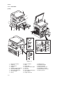
18
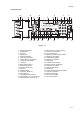
19
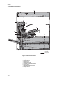
20

21

22

23
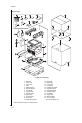
24
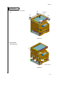
25

26
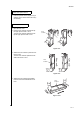
27
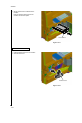
28

29

30
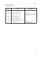
31
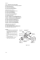
32
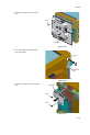
33
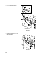
34
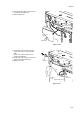
35
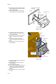
36
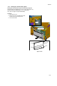
37
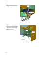
38

39
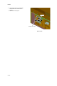
40

41
42

43
44
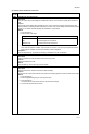
45
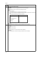
46
47
48
49

50

51

52
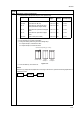
53
54
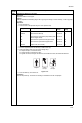
55
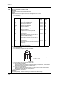
56

57

58

59
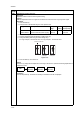
60
61
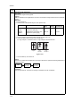
62
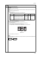
63
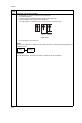
64
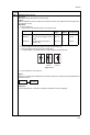
65

66
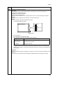
67

68
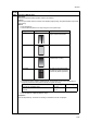
69

70
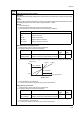
71
72

73
74
75

76

77

78

79
80
81

82

83
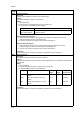
84
85

86
87
88

89
90
91
92

93

94

95
96

97

98
99
100
101
102

103
104
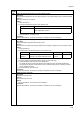
105
106

107
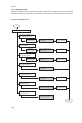
108
109

110
111
112
113

114
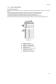
115
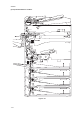
116

117

118
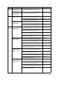
119

120

121
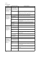
122
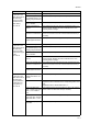
123

124
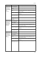
125
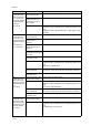
126

127

128

129

130
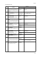
131
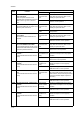
132

133
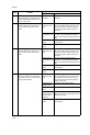
134

135
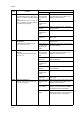
136

137
138

139

140
141

142
143
144

145
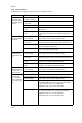
146

147
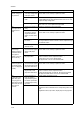
148
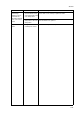
149

150
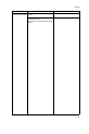
151

152

153

154
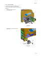
155

156
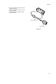
157
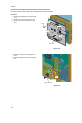
158
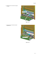
159

160
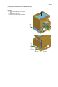
161
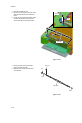
162

163

164
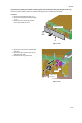
165
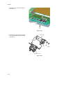
166

167
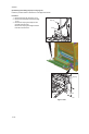
168

169
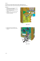
170

171
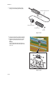
172

173
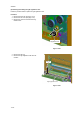
174
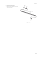
175
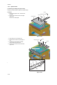
176
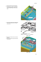
177
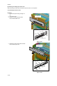
178

179

180
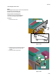
181
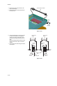
182

183

184
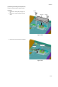
185

186
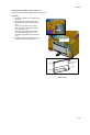
187

188

189

190

191

192

193
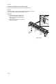
194
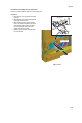
195
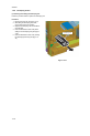
196

197

198
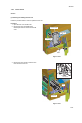
199
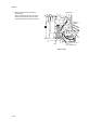
200

201
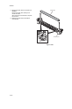
202
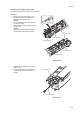
203
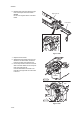
204
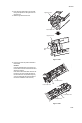
205
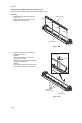
206
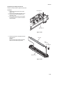
207
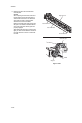
208

209

210

211
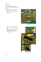
212

213
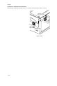
214
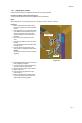
215
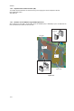
216

217

218

219

220
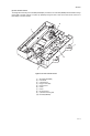
221
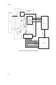
222
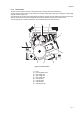
223

224

225
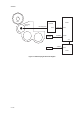
226
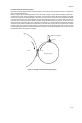
227
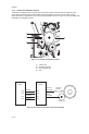
228
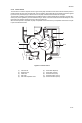
229
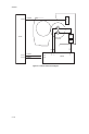
230
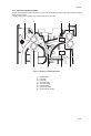
231

232
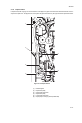
233

234

235

236
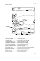
237

238
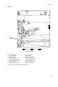
239
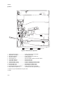
240
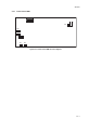
241

242

243
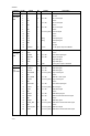
244

245
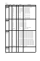
246
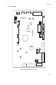
247

248

249
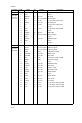
250
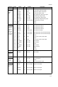
251
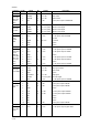
252
253
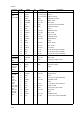
254
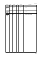
255
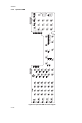
256

257
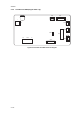
258
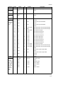
259
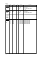
260
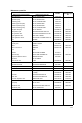
261

262
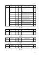
263
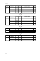
264

265
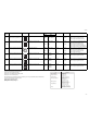
266

267
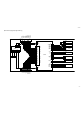
268
269
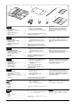
270
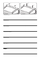
271
272
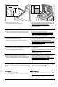
273
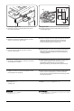
274
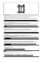
275

276

277
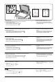
278
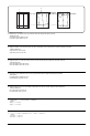
279
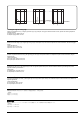
280

281
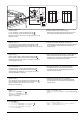
282

283

284

285
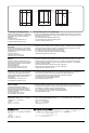
286
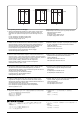
287

288
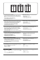
289
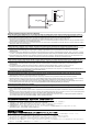
290
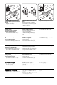
291

292
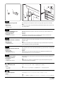
293

294

295
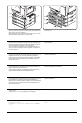
296

297
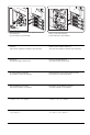
298
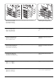
299

300
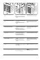
301
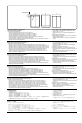
302
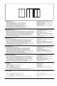
303

304

305

306
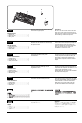
307
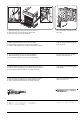
308
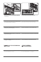
309
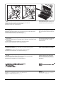
310
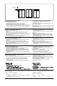
311
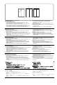
312
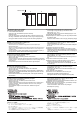
313
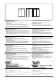
314

315
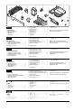
316

317

318
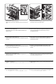
319
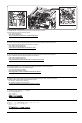
320
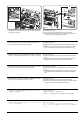
321
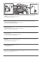
322
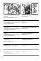
323
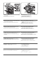
324
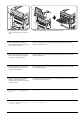
325
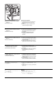
326

327
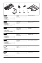
328

329
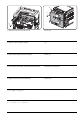
330

331
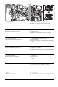
332

333

334
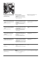
335

336

337

338
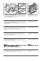
339
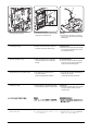
340

341
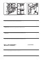
342

343
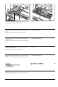
344
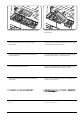
345
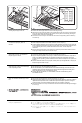
346
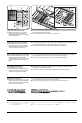
347

348
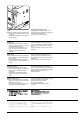
349
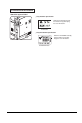
350

351
352

353
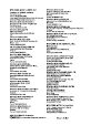
354
355

SERVICE
MANUAL
Published in October 2009
842KJ112
2KJSM062
Rev.2
TASKalfa 181
TASKalfa 221
Specifications:
|
Accompanying Data:
Kyocera TASKalfa 181 All in One Printer, Fax Machine PDF Service Manual (Updated: Saturday 5th of November 2022 08:44:10 PM)
Rating: 4.7 (rated by 42 users)
Compatible devices: TASKalfa 3510i, KM-6030, ECOSYS P2040dw, TASKalfa 4501i, KM-P4845w, TASKalfa 6500i, TASKalfa 1801, FS-1900N.
Recommended Documentation:
Kyocera TASKalfa 181: Text of Service Manual
(Ocr-Read Version Summary of Contents, UPD: 05 November 2022)
-
47, 2KJ/2KH 1-3-7 U005 Copying without paper Description Simulates the copy operation without paper feed. Purpose To check the overall operation of the machine. Method 1. Press the start key. 2. Select the item to be operated. 3. Press the start key. 4. Press the interrupt key. The copy mode screen is displayed. 5. Set the operation conditions required on the co…
-
271, 2 1 1 D D Installing the DP 1. Remove the 2 screws (1). 2. Install 2 pins (D). Installation du DP 1. Déposez les 2 vis (1). 2. Installez 2 goupilles (D). Instalación del DP 1. Quite los 2 tornillos (1). 2. Instale 2 pasadores (D). Installieren des DP 1. Entfernen Sie die 2 Schrauben (1). 2. 2 Rändelschrauben (D) eindrehen. Installazione del DP 1. Rimuovere le 2 viti (1). 2. Inserire 2 …
-
93, 2KJ/2KH 1-3-53 U402 Adjusting margins of image printing Description Adjusts margins for image printing. Purpose Make the adjustment if margins are incorrect. Adjustment 1. Press the start key. 2. Select the item to be adjusted using the cursor up/down keys. 3. Press the interrupt key. 4. Press the start key to output a test pattern. 5. Change the setting value using the curso…
-
207, 2KJ/2KH 1-5-55 (5) Detaching and refitting the heat roller Follow the procedure below to replace the heat roller. Procedure 1. Separate the right and left fuser unit (see page 1-5-49). 2. Remove the fuser heater (see page 1-5-51). 3. Remove the heat roller separation claws (see page 1-5-54). 4. Press the heat roller bush in the rear side of the right fuser unit from outside to make…
-
76, 2KJ/2KH 1-3-36 U110 Checking the drum count Description Displays the drum counts for checking. Purpose To check the drum status. Method 1. Press the start key. The drum counter count is displayed. Completion Press the stop/clear key. The screen for selecting a maintenance item No. is displayed. U130 Initial setting for the developing unit Description Replenishes toner t…
-
131, 2KJ/2KH 1-4-17 (2) Self diagnostic codes Code Contents Remarks Causes Check procedures/corrective measures C0030 Fax control PWB system problem Processing with the fax software was disabled due to a hardware or software problem. Defective fax con- trol PWB. Replace the fax control PWB and verify the operation. C0070 Abnormal detection of fax control PWB in…
-
295, 2 1. A A A 1 2 1 2 1 1 2 2 カセットは最大 3 段まで装着可能。 (MFP(プリンタ標準機)の 22 枚機は 2 段まで装 着可能) 注意 カセットを 2 段以上装着する場合は、先に全て のカセットを重ねた状態にしてから、本体をの せること。 1. 下側カセット (A) 後部の位置決めピン (1) に、…
-
126, 2KJ/2KH 1-4-12 (14) A paper jam in the paper conveying sec- tion is indicated dur- ing copying (misfeed in registration/trans- fer section). Jam code 30 Deformed guides along the paper conveying path. Check visually and replace. Broken registration switch, cassette feed switch 1 or duplex paper conveying switch actuator. Check visually and replace switch. Defective switch. Run mainte…
-
147, 2KJ/2KH 1-4-33 (6) The MP solenoid does not operate. 1. Broken solenoid coil. Check for continuity across the coil. If none, replace the solenoid. 2. Poor contact in the con- nector terminals. Reinsert the connector. Also check for continuity within the con- nector cable. If none, remedy or replace the cable. 3. Defective cassette PWB. Run maintenance item U032 and check if fo…
-
341, 5 11 12 11 A 12 E E 10 8. FAX 制御回路基板組立 (A) のフック (11)2 箇所をシールドカバーの 引っ掛け部 (12) に挿入する。 7. Plug the white connector on the wire (E) into YC10 (10) on the engine circuit board. 8. Fit the 2 hooks (11) on the fax control circuit board assembly (A) into the latch (12) in the shielding cover. 7. Raccordez le …
-
129, 2KJ/2KH 1-4-15 (30) A paper jam in fin- isher is indicated dur- ing copying (finisher eject jam). Jam code 84 Defective paper conveying switch. With 5 V DC present at YC2-23 on the finisher control PWB, check if YC2-21 on the finisher control PWB remains low or high when the paper conveying switch is turned on and off. If it does, replace the paper conveying switch. Check if the f…
-
233, 2KJ/2KH 2-1-17 2-1-8 Duplex section In duplex mode, after copying on to the reverse face of the paper, the paper is reversed in the switchback section and con- veyed to the duplex unit. The paper is then conveyed to the paper feed section by the upper and lower duplex feed rollers. Figure 2-1-18 Duplex section 1 3 5 6 4 2 (1) Feedshift guide (2) Duplex feed pulley (3) Upper duple…
-
344, 8 21 20 19 18 18 操作部シートの取り付け 15.はめ込み部にマイナス小ドライバーを挿入し、カバー(18) を取り外す。 16.操作部左カバー(19) を取り外す。 17.ツメ (20) を持ち上げて操作部シートカバー(21) を取り外す。 Installing the operation section sheet 15.Insert a flat-head screwdriver into the latch and re…
-
324, 9 C N 2 33 33 F 33 34 左上カバーの取り付け 23.左上カバー(F) の爪 (33)6 箇所を挿入し、前側へスライドさせる。 24.はめ込み部 (34) をはめ込み、左上カバー(F) を取り付ける。 Anbringen der oberen linken Abdeckung 23.Schieben Sie die 6 Laschen (33) an der oberen linken Abdeckung (F) in Position und schieben Sie die Abdeckung nach vorne. 24…
Kyocera TASKalfa 181: Recommended Instructions
AS1000 — Amplifier, NP101, CARDIO COMFORT AMBITION, H 2661 BP, 34102


-
www.hp.com/mobile/OJP6230HP Oicejet Pro 6230© 2014 Hewlett-Packard Development Company, L.P.Learn moreElectronic Help: Install the electronic Help (which is the user guide) by selecting it from the recommended software during software installation. The Help provides information about product features, printing, troubleshooting, and support; as well as notices, environmental, and regu …
Officejet Pro 6230 24
-
Ordering InformationAll-in-OneCX8400Print | Copy | Scan | PhotoProduct Name Product Code UPCEpson Stylus® CX8400 all-in-one C11C690201 0 10343 86523 5Epson Stylus CX8400 all-in-one (Canada) C11C690202 0 10343 86577 868 Black High-capacity dual pack ink cartridge T068120-D1 0 10343 86633 169 Black ink cartridge T069120 0 10343 86068 169 Cyan ink cartridge T …
Stylus CX8400 2
-
3/27/97 11:24 am Final Version Given to Printer…………………………………………………………………………………HP Company Confidential HP OfficeJet Series 500………………………………………………………………………………………..User’sGuide …
DesignJet 500 130
-
Competitive ComparisonPhaser® 8560 Phaser 8560 HP LaserJet 3800More value ———————————————— LaserJet 3800: …………………. $799* • The Phaser 8560 offers superior performance, print quality Phaser 8560N: ………………………….. $799* LaserJet 3800n: ………………. $899* and ease of use for less money Phaser 8560DN: …
Phaser 8560 2
-
BPB317SBPB318SBPB319SBPC303SBPC304SBPC305SBPC307SBPC308SRead this manual carefully before you use the product and keep it handy for future reference. For safe and correct use, please be sure to read theSafety Information before using the machine.nThis manual briefly describes the procedure for installing this machine.For more details about installation and other information, seeUser Guidein the ma …
SP C231SF 2
-
Photo PrinterQuick Start GuideseriesQT51427V01The following FINE Cartridges are compatible with this product.For information on product specifications, please visit our website atwww.usa.canon.comQT5-1427-V01 XXXXXXXX © CANON INC. 2008 PRINTED IN VIETNAM …
iP2600 — PIXMA Color Inkjet Printer 72
-
www.xerox.com/msds (U.S./Canada)www.xerox.com/environment_europewww.xerox.com/office/businessresourcecenterwww.xerox.com/office/6140supportwww.xerox.com/msds (U.S./Canada)www.xerox.com/environment_europewww.xerox.com/office/businessresourcecenterwww.xerox.com/office/6140supportXerox® Phaser® 6140Quick Use GuideXerox Phaser 6140Color Laser PrinterCopyright © 2009 Xerox Corporat …
PHASER 6140 5
-
Montageanleitung und HandhabungshinweiseSchaukelArt.-Nr. 08398-600Der Umwelt zuliebe: wir drucken auf 100% Altpapier!DGBFNLEIPL2Dieses KETTLER-Produkt wurde nach dem aktuellen Stand der Sicherheitsvorschriften kon-struiert und unter einer ständigen Qualitätsüberwachung gefertigt. Die hieraus gewonnenenErkenntnisse lassen wir in unsere Entwicklung einfließen. Aus …
08398-600 18
-
User Guide Set Up & Start Up Basic Copier Operations Key Operator Functions Toshiba America Business Solutions, Inc. © 2004 Training and Dealer Development Toshiba America Business Solutions, Inc. © 2004 Training and Dealer Development …
e-studio230 36
Additional Information:
Popular Right Now:
Operating Impressions, Questions and Answers:
-
-
Repair manuals
-
Printers
-
Kyocera
-
TASKalfa 181
-
Drivers
9
-
Repair manuals
5
-
User manuals
12

Kyocera TASKalfa 181 installation instructions
(22 pages)
- Languages:English
-
Type:
PDF -
Size:
557.63 KB -
Description:
IB-51 WEB Browser Management Setup Guide
WEB Browser Management Guide
Preview

Kyocera TASKalfa 181 installation instructions
(19 pages)
- Languages:English
-
Type:
PDF -
Size:
364.89 KB -
Description:
KM-NET ADMIN Operation Guide for Ver 3.0
Operation Guide for KM-NET ADMIN Ver. 3.0.2211c
Preview

Kyocera TASKalfa 181 installation instructions
(38 pages)
- Languages:English
-
Type:
PDF -
Size:
3.32 MB -
Description:
Mac Driver Setup Guide Rev 4.2.018.06
Cover Installation and Setup of the Mac Driver
Preview

Kyocera TASKalfa 181 installation instructions
(66 pages)
- Languages:English
-
Type:
PDF -
Size:
866.8 KB -
Description:
KYOmulticode 1.0/PCL Barcode Flash 3.0 Quick Install Guide
Quick Installation Guide
Preview

Kyocera TASKalfa 181 service manual
(355 pages)
- Languages:English
-
Type:
PDF -
Size:
27.82 MB
Preview
Kyocera TASKalfa 181 (Printers) service manuals in PDF format will help to find failures and errors and repair Kyocera TASKalfa 181 and restore the device’s functionality.
Table Of Contents
📚 Kyocera TASKalfa 181 Service Manual
-
TABLE OF CONTENTS
- Service manual
- Parts list
Manufacturer: Kyocera
Category: All in One Printer

Download Manual (720 KB)
Related manuals
Kyocera TASKalfa 181 Service Manual
All in One Printer
Kyocera TASKalfa 181 Operation Manual
All in One Printer
Kyocera TASKalfa 181 User Manual
All in One Printer
Kyocera TASKalfa 181 Installation Manual
Printer Accessories
Kyocera TASKalfa 181 Operation Manual
All in One Printer
Kyocera TASKalfa 181 Operation Manual
All in One Printer
Kyocera TASKalfa 181 Installation Manual
All in One Printer
Kyocera TASKalfa 181 Operation Manual
All in One Printer
Kyocera TASKalfa 181 Operation Manual
All in One Printer
Kyocera TASKalfa 181 Service Manual
All in One Printer
More by Kyocera
Kyocera 5550ci Operation Manual
All in One Printer
574 pages
Nov 16, 2022
Kyocera Verve Get Started Manual
Cell Phone
24 pages
Nov 18, 2022
Kyocera FS-C2026MFP+ Service Manual
All in One Printer
321 pages
Nov 24, 2022
Kyocera KM-6030 Operation Manual
Printer
124 pages
Nov 27, 2022
Kyocera Kona Get Started
Cell Phone
16 pages
Nov 30, 2022
SEE MORE ❯