Инструкция для GPS/GNSS приемника Topcon GR-5
![]()
Руководство по эксплуатации GPS/GNSS приемника Topcon GR-5
| Имя файла: | topcon_gr5.pdf |
| Размер файла: | 6.64 MB |
| Тип файла: | application/pdf |
| Посещений: | 5673 Посещений |
| Дата последнего обновления: | 16-12-15 |
-
Скачать -
Просмотр
- Manuals
- Brands
- Topcon Manuals
- Receiver
- GR-5
- Operator’s manual
Gnss
-
Contents
-
Table of Contents
-
Troubleshooting
-
Bookmarks
Quick Links
Related Manuals for Topcon GR-5
Summary of Contents for Topcon GR-5
-
Page 3
Rev A ©Copyright Topcon Positioning Systems, Inc. February, 2011 All contents in this manual are copyrighted by Topcon. All rights reserved. The information contained herein may not be used, accessed, copied, stored, displayed, sold, modified, published, distributed, or otherwise reproduced… -
Page 4
ECO#4074… -
Page 5: Table Of Contents
Calculating Absolute Positions ……1-4 Essential Components for Quality Surveying ..1-4 Calculating Differential Positions …… 1-5 Conclusion …………1-8 GR-5 Receiver …………..1-8 GR-5 Features …………1-10 MINTER …………. 1-10 Data and Power Ports ……… 1-15 External Radio Antenna Connector ….1-16 Connector …………
-
Page 6
Establishing a USB Connection ……… 2-24 Bluetooth Module Configuration ……..2-24 Collecting Almanacs and Ephemerides ……2-27 Chapter 3 GR-5 Configuration ……….3-1 Managing the Radio Modem ……….3-2 Connecting with the Radio Modem ……3-3 Modem Configuration ……….3-4 Configuring a Digital UHF Radio Modem .. -
Page 7
Table of Contents Chapter 4 GR-5 Receiver Setup and Survey ……. 4-1 Receiver Setup …………..4-1 Step 1: Set up the Receivers ……..4-1 Step 2: Measure Antenna Height ……4-3 Step 3: Collect Data ……….4-7 MINTER Operation …………4-8 Static Surveying for Base Stations …….. -
Page 8
GPS Board Details …………. A-8 Bluetooth Module Details ………. A-9 Internal TPS Spread Spectrum Modem Details ..A-10 Internal Topcon UHF Modem General Specification Details ……….A-11 Internal UHF Satel Modem Details ……A-12 Optional GSM/GPRS Module Details ……. A-13 Connector Specifications ………. -
Page 9
Table of Contents WEEE Directive ………….. C-2 Appendix D Warranty Terms ………… D-1 Index P/N 7010-1004… -
Page 10
Table of Contents Notes: GR-5 Operator’s Manual… -
Page 11: Preface
Preface Preface Thank you for purchasing this Topcon product. The materials available in this Manual (the “Manual”) have been prepared by Topcon Positioning Systems, Inc. (“TPS”) for owners of Topcon products, and are designed to assist owners with the use of the receiver and its use is subject to these terms and conditions (the “Terms and Conditions”).
-
Page 12
Windows® is a registered trademark of Microsoft Corporation. The Bluetooth® word mark and logos are owned by Bluetooth SIG, Inc. and any use of such marks by Topcon Positioning Systems, Inc. is used under license. Other product and company names mentioned herein may be trademarks of their respective owners. -
Page 13
Terms and Conditions herein and in any case only with a single receiver or single computer. You may not assign or transfer the Software or this license without the express written consent of TPS. This license is effective until terminated. You may terminate the license at any time by destroying the Software and Manual. -
Page 14: Manual Conventions
Notification that an action has the potential to adversely affect system operation, system CAUTION performance, data integrity, or personal health. Notification that an action will result in system damage, loss of data, loss of warranty, or personal WARNING injury. GR-5 Operator’s Manual…
-
Page 15: Additional Documentation
• Satel radio modem version 3.44f • Digital radio modem version 1.6RevG If new versions of the firmware are released, the user can load them to the GR-5 as described on “Loading New Firmware Using TRU” on page 5-21. P/N 7010-1004…
-
Page 16
Preface Notes: GR-5 Operator’s Manual… -
Page 17: Chapter 1 Introduction
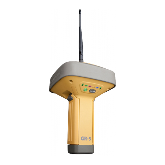
Chapter 1 Introduction The GR-5 receiver is a multi-frequency, GNSS receiver built to be the most advanced and compact receiver for the surveying market. The receiver is a multi-function, multi-purpose receiver intended for precision markets. Precision markets means markets for equipment,…
-
Page 18
Introduction Figure 1-1. GR-5 Receiver GR-5 Operator’s Manual… -
Page 19: Principles Of Operation
Principles of Operation Principles of Operation Surveying with a professional-grade GNSS receiver can provide users with accurate and precise positioning; a fundamental requirement for any surveying project. This section gives an overview of existing and proposed Global Navigation Satellite Systems (GNSS) and receiver functions so that basic operating principles can be applied.
-
Page 20: Calculating Absolute Positions
Essential Components for Quality Surveying Achieving quality positioning results from the GR-5 requires an understanding of the following elements: • Accuracy — The accuracy of a position that is delivered by a…
-
Page 21: Calculating Differential Positions
Base and the Remote receivers. – The quality of observed measurements can also affect accuracy, and for this reason Topcon GNSS products use sophisticated and patented techniques to produce highly precise measurements. However, these measurements can…
-
Page 22
RTCM message formats (v3 or greater) for all RTK and DGPS communication needs. Several legacy correction message formats are also provided by Topcon GNSS products in order to support interoperability with older GNSS systems, but their use is now deprecated. -
Page 23
RTK accuracy of up to 10mm horizontal and 15mm vertical. The GR-5 supports three widely used network RTK implementation techniques, specifically, VRS, FKP, and MAC. • Virtual reference station (VRS). The network software collects raw data measurements from several reference stations that belong to a network. -
Page 24: Conclusion
The receiver processor controls the process of signal tracking. 1. The GR-5 tracks the GIOVE-A and GIOVE-B test satellites. The signals from these satellites are used for signal evaluation and test purposes only.
-
Page 25
This allows the operator to double check real-time results obtained in the field. The GR-5 comes in one of the following configurations: • with an FH915 Plus TX/RX/RP radio modem •… -
Page 26: Gr-5 Features
The GR-5 is a 216-channel GNSS receiver with two data ports, a power port, a multi-system GNSS board, and a radio modem communications board, an interface for controlling and viewing data logging, and also includes: •…
-
Page 27
FUNCTION FUNCTION Power Button Button Figure 1-2. GR-5 MINTER displays the data recording status. See “The The REC LED FUNCTION button” on page 1-13 for more information on REC LED behavior when using the FUNCTION button. • Green blinks – each blink indicates that data is being written to the SDHC card. -
Page 28
Table 1-1 The RX TX LED describes the LED colors and patterns for the different modems available for the GR-5 receiver. Table 1-1. RX TX LED Indications • No light – modem is turned off. -
Page 29
GR-5 Receiver • Solid blue light – the Bluetooth module is on and a connection has been established. • No light – the Bluetooth module is off. turns the receiver on and off. The Power button switches the receiver between information… -
Page 30
No light Release to stop data recording. seconds Pressed for 5–8 Release to turn serial port A baud rate to seconds 9600 bps. Pressed for > 8 No light No function (data recording still on). seconds GR-5 Operator’s Manual 1-14… -
Page 31: Data And Power Ports
GR-5 Receiver Data and Power Ports The GR-5 has the following three ports (Figure 1-3): • USB – rimmed in yellow; used for high-speed data transfer and communication between the receiver and an external device. The body of the connector on the corresponding cable is yellow.
-
Page 32: External Radio Antenna Connector
Introduction External Radio Antenna Connector The radio antenna connects to the external antenna connector on the GR-5 radome (Figure 1-4). The radio antenna uses a reverse polarity TNC connection or BNC connection depending on the installed radio modem. External Antenna Connector Figure 1-4.
-
Page 33: Connector
5/8» thread pole/adapter or the quick disconnect (see “The quick disconnect adapter” on page 1-24 for details). Bottom Connector for Standard Setups Figure 1-5. GR-5 Quick Connector SDHC and SIM Card Slots The SDHC and SIM card slots reside under the batteries near the base of the dome.
-
Page 34
SIM card installed can be accessed via TRU for configuration purposes. A SIM card can be purchased from a local cellular provider. Card Slot (for SDHC card) Figure 1-6. GR-5 Card Slot Example GR-5 Operator’s Manual 1-18… -
Page 35: Batteries
GR-5 Receiver Batteries The GR-5 receiver comes equipped with two detachable, rechargeable batteries (Figure 1-7) for powering the receiver. Figure 1-7. GR-5 Batteries The receiver draws power from one battery at a time before switching to the second battery. Each detachable battery can provide between 5hrs.
-
Page 36: Cables
Cables The GR-5 package includes standard communication and power cables for configuring the receiver and providing a power source to the receiver. Table 1-3 lists the cables included in the GR-5 package. Table 1-3. GR-5 Package Cables Cable Description Cable Illustration…
-
Page 37: Other Accessories
GR-5 Receiver Other Accessories (p/n 22-034101-01) charges the internal The power supply unit batteries when connected to a grounded outlet (Figure 1-8). This unit converts the alternating current (AC) normally supplied from an electrical outlet to a direct current (DC) used to charge the batteries and/or power the receiver.
-
Page 38
SS/GSM Antenna UHF/GSM Antenna Figure 1-9. Modem Antenna The heavy duty tripod The GR-5 2m fixed height Tripod and Pole (22-050501-01) is shown in Figure 1-10. The pole (22-050908-01) is not pictured. Figure 1-10. Tripod For more details on the accessories and package options available for the GR-5, contact a local Topcon dealer. -
Page 39: Optional Accessories
Optional Accessories Topcon offers a wide variety of accessories especially designed to extend job reliability and efficiency. For more details on the optional accessories available for the GR-5, contact a local Topcon dealer. (p/n 22-006008-01 The universal tribrach and tribrach adapter and p/n 22-006009-011) are used to level the tripod and secure the receiver or antenna to the tripod (Figure 1-11).
-
Page 40
A hand-held controller Rover systems to be configured and monitored directly in the field. TopSURV (field data collection software) and TRU (receiver configuration and monitoring software) can be used on Topcon controllers to configure and manage the receiver. FC-25 FC-2500 Figure 1-14. -
Page 41
See “Assembling the AA Battery Shell” on page 2-17 for details on how to attach the pack to the GR-5. Figure 1-16. AA Battery Pack Do not use rechargeable AA batteries. -
Page 42: Option Authorization File (Oaf)
To grounded outlet Figure 1-19. Battery Recharger Option Authorization File (OAF) Topcon Positioning Systems issues an Option Authorization File (OAF) to enable the specific options that customers purchase. An Option Authorization File allows customers to customize and configure the receiver according to particular needs, thus only purchasing those options needed.
-
Page 43
• RS-232C and USB port connectivity 1. There is no separate option for GALILEO signals in the OAF. The GR-5 tracks the GIOVE-A and GIOVE-B test satellites. The signals from these satellites are used for signal evaluation and test purposes only. -
Page 44
Introduction Notes: GR-5 Operator’s Manual 1-28… -
Page 45: Pre-Survey Preparation
Chapter 2 Pre-survey Preparation Before beginning to survey with the GR-5 receiver, the following software needs to be installed and configurations need to be applied: Install receiver configuration software See “Installing Topcon Software” on page 2-2. Optional: install SDHC card and/or SIM card See “Installing the Optional SDHC and SIM Cards”…
-
Page 46: Installing Topcon Software
Pre-survey Preparation Installing Topcon Software The Topcon GPS+ CD includes the following software programs used for configuring and maintaining the receiver. This software is also available on the TPS website to registered users. • PC-CDU Lite ver. 7.12 or newer •…
-
Page 47: Installing Tru
Installing Topcon Software To Install PC-CDU: 1. Create a PC-CDU folder on the hard drive and place the compressed PC-CDU zip file (retrieved from either the website or the GPS+ CD) in this folder. 2. Navigate to the PC-CDU folder and double-click the PC- CDU_MS zip file.
-
Page 48: Installing The Optional Sdhc And Sim Cards
2 GB of memory. The recognizable capacity is controlled through the Memory option in an OAF. Once installed, the card(s) generally remains installed. The card can then be accessed via the receiver board using a data port or Bluetooth wireless technology. GR-5 Operator’s Manual…
-
Page 49
Installing the Optional SDHC and SIM Cards (Figure 2-3): To install the SDHC card 1. Ensure the receiver is turned off. 2. Remove the battery to the left of the MINTER. 3. Carefully insert the SDHC card, label side down, into the SDHC card slot located at the top of the battery compartment. -
Page 50
3. Carefully insert the SIM card, label side up, into the SIM card slot located at the top of the battery compartment. Figure 2-4. Install SIM Card Once the receiver is turned on, the receiver board will detect the SIM card and it will be ready to use as needed. GR-5 Operator’s Manual… -
Page 51: Charging The Batteries
Do not use as a power source during surveying. The power supply unit can be connected to the charging cradle or directly to the GR-5. The power supply has the following specifications: • input voltage – between 100 and 240 V AC •…
-
Page 52
The battery charger can also be attached to a tripod, belt, or RTK pole to provide external power to the base station or rover. Before using the GR-5, fully charge the batteries for maximum operating time (Figure 2-6 on page 2-10). -
Page 53: Charging Temperatures
• while they are attached to the GR-5 • while they are attached to the charging cradle If the batteries are attached to the GR-5 or to the charging cradle, an approximately 6-hour charge cycle will fully charge the batteries; the batteries charge simultaneously.
-
Page 54: Leaving The Batteries On Charge
The batteries can be safely left in the receiver or the charging cradle once charging is complete. Doing so will not overcharge or damage the batteries. The batteries can also be attached/detached to/from the receiver or charging cradle at any time without harming the batteries, the GR-5 Operator’s Manual 2-10…
-
Page 55: Power Management
When returning the batteries to the receiver or cradle, charging is automatically resumed. Power Management Topcon’s PC-CDU software provides an interface for various configuration, monitoring, and management functions for the receiver. For power management of the receiver, PC-CDU enables the power source, enables the charging mode, and displays the current voltage for the batteries.
-
Page 56
Figure 2-8. Select Charger Mode 5. Select the Turn on/off Slots drop-down list to set power output on internal slots (Figure 2-9). • On – slot C is powered if the receiver is turned on GR-5 Operator’s Manual 2-12… -
Page 57
Power Management • Off – internal slot is not powered even if the receiver is turned on • Always – internal slot is powered even if the receiver is turned off Figure 2-9. Select Power Output Modes – Ports and Slots 6. -
Page 58: Powering The Receiver
0.4 V between the batteries. view the BATT LED To check the status of the internal batteries, or check the status using available Topcon software. • Check the BATT LEDs for battery status. – A green light indicates greater than 85% charge.
-
Page 59: Using The Detachable Batteries
Powering the Receiver Using the Detachable Batteries The GR-5 receiver comes with two detachable, rechargeable batteries and an AA battery shell. Each battery can provide between 5 and 10 (approximate) hours of operation at room temperature, depending on the mode of the receiver and the capacity of the battery.
-
Page 60: Attaching The Batteries
Figure 2-12. Insert the GR-5 Batteries Detaching the Batteries To detach the batteries from the GR-5, so that they can be charged or replaced: Using the clip at the top of the battery, gently pull down and out to detach the battery from the receiver (Figure 2-13).
-
Page 61: Assembling The Aa Battery Shell
Powering the Receiver Figure 2-13. Detach the GR-5 Batteries Assembling the AA Battery Shell To assemble the AA battery shell to the GR-5 (Figure 2-14): Do not use rechargeable AA batteries. Do not use the AA battery shell when the radio CAUTION modem is in transmitter mode.
-
Page 62: Surveying While Charging
Pre-survey Preparation 4. Insert the AA battery shell into the battery compartment of the receiver as shown in “To attach the batteries to the GR-5 (Figure 2-12):” on page 2-16. Surveying while Charging The user can execute any kind of surveying while charging the internal batteries attached to the GR-5 without degradation of performance.
-
Page 63
Powering the Receiver 1. Connect one end of the cradle-to-receiver cable to the charging cradle. 2. Connect the other end to the power port on the receiver. Connecting the charging cradle and the receiver using the cradle-to-receiver charging cable Figure 2-15. Connect the Charging Cradle and Receiver (Figure 2-16 on To connect the receiver to an auxiliary battery page 2-20):… -
Page 64: Turning On/Off The Receiver
To turn OFF the receiver, press and hold the power button for more than one and less than four seconds (until both the STAT and the REC LEDs are off). This delay (about 1 second) prevents the receiver from being turned off by mistake. GR-5 Operator’s Manual 2-20…
-
Page 65: Connecting The Receiver And A Computer
Connecting the Receiver and a Computer Connecting the Receiver and a Computer Topcon’s TRU and PC-CDU software products provide an interface for various configuration, monitoring, and management functions for the receiver. To configure, manage files, or maintain the receiver, connect the…
-
Page 66
1. Connect the receiver and a computer using an RS232 cable or USB cable and PC-CDU as seen below. 2. Click Configuration Receiver General. 3. In the Turn on/off Slots area, ensure the Slot 2 (C) check box is enabled. GR-5 Operator’s Manual 2-22… -
Page 67: Establishing An Serial (Rs232) Cable Connection
Connecting the Receiver and a Computer Establishing an Serial (RS232) Cable Connection 1. Using the RS232 cable, connect the serial port of the computer (usually COM1) to the receiver’s serial port. 2. Press the power button on the receiver to turn it on. 3.
-
Page 68: Establishing A Usb Connection
Pre-survey Preparation To successfully connect to the GR-5 receiver, do not check the External Receiver checkbox in the NOTE Connection Parameters dialog box. See “Configuring the Receiver Using TRU” on page 3-19 for more information on configuring the receiver. Establishing a USB Connection Make sure the computer has the TPS USB driver installed and that the USB option is enabled.
-
Page 69
Bluetooth Module Configuration 1. Using the RS232 cable, connect the serial port of the computer (usually COM1) to the receiver’s serial port. If needed, turn on the receiver and computer. 2. Run the TRU program and click Device Application Mode Receiver Managing. -
Page 70
• Authentication – enable to require a PIN before two Bluetooth enabled devices (such as, the receiver and a computer) can establish a communication link. The two devices must use the same PIN. • Bluetooth name – the name of the Bluetooth module. GR-5 Operator’s Manual 2-26… -
Page 71: Collecting Almanacs And Ephemerides
Collecting Almanacs and Ephemerides • Bluetooth address – the unique electronic address for the module. • Firmware base – the current firmware base version. • Firmware version – the current firmware version of the Bluetooth module. Figure 2-21. Bluetooth Parameters 5.
-
Page 72
• If the last known receiver position, stored in the NVRAM, is different from the present position by several hundred kilometers. • After loading a new OAF. • After loading new firmware. • After clearing the NVRAM. • Before surveying GR-5 Operator’s Manual 2-28… -
Page 73: Gr-5 Configuration
This data is then processed using post-processing software (for example, Topcon Tools). use the following When configuring receivers for RTK surveying, checklist to ensure the receivers are properly set up.
-
Page 74: Managing The Radio Modem
See “Receiver Setup” on page 4-1 for more information. Managing the Radio Modem TRU is Topcon’s radio modem configuration utility for modems embedded in Topcon receivers. TRU provides the following functions: • Connecting a computer to an integrated radio modem via a serial port or Bluetooth wireless technology.
-
Page 75: Connecting With The Radio Modem
Managing the Radio Modem Connecting with the Radio Modem 1. Turn on the receiver. Connect the computer and receiver using an RS-232 cable or Bluetooth wireless technology. 2. Open TRU. Click Device Application Mode Modem Managing. Then click Device Connect. Figure 3-1.
-
Page 76: Modem Configuration
GR-5 Configuration 5. All internal modems for the GR-5 are on port C. Select the Internal Modem check box and choose ser/c from the drop-down menu. Click Connect. Figure 3-3. Connection Parameters 6. TRU will search through port speeds and flow settings until it finds the modem.
-
Page 77: Configuring A Digital Uhf Radio Modem
Settings icon to configure the GR-5 internal modem. Figure 3-5. Modem Managing 2. If the GR-5 contains a Digital UHF modem (other name Digital AW401), the Topcon Digital UHF screen appears. The General tab displays information on the modem model, and the product identification.
-
Page 78
The settings can be read-only (marked by the icon) or changeable (marked by the icon). Figure 3-7. UHF Modem Settings • Mode – displays whether the UHF or GSM/CDMA band is used for communication. GR-5 Operator’s Manual… -
Page 79
Managing the Radio Modem • Baud rate – select a baud rate for the modem’s serial port. The user can adjust the baud rate. This is the flow rate on the serial port connecting the modem to the GPS board. 38400 is the recommended rate with this radio. -
Page 80
4. When finished configuring the radio modem, always disconnect from TRU before exiting to prevent conflicts with serial port management. If needed, launch TRU and set up the receiver to run as an RTK Base station or RTK Rover. GR-5 Operator’s Manual… -
Page 81: Configuring An Fh915+ Radio Modem
Settings icon to configure the GR-5 internal modem. This page is intentionally left blank Figure 3-8. Modem Managing 2. If the GR-5 contains an FH915+ modem, the Topcon — FH915+ screen appears. The General tab displays the manufacturer, the modem model, and the product identification information.
-
Page 82
• Pressing the Refresh button renews the list. • Pressing the Import button imports settings from a file. • Pressing the Export button saves settings in a file. • Pressing the Load button writes new setting into the modem. GR-5 Operator’s Manual 3-10… -
Page 83
Managing the Radio Modem • The settings can be read-only (marked by the icon) or changeable (marked by the icon). This page is intentionally left blank Figure 3-10. Settings — Settings Page The Settings page allows viewing and changing general communication parameters, and parameters specific for the modem. -
Page 84
(when in Master mode). It can be a number from 0 to 14 digits. • Send Time, s – specifies a time interval in seconds, is used to ensure reliable communication between the pair of modems (master — slave) and avoid unnecessary modem GR-5 Operator’s Manual 3-12… -
Page 85
Managing the Radio Modem reinitialization. The transmitting modem will send the service word to the receiving modem in every ‘sndtime’ seconds. The service word does not affect the differential corrections (RTCM or CMR messages) in any way. NOTICE If the parameter is set to zero, the service word is not be used in data transmission. -
Page 86: Configuring A Satel Radio Modem
25cm between the user and the NOTICE radio modem. 1. On the TRU Main Screen in Modem Managing mode double- click on the Settings icon to configure the GR-5 internal modem. This page is intentionally left blank Figure 3-11. Modem Managing GR-5 Operator’s Manual…
-
Page 87
Managing the Radio Modem 2. If the GR-5 contains a Satel modem, the Satel screen appears. The General tab displays the modem model, and the product identification information. This page is intentionally left blank Figure 3-12. Settings — General Tab 3. -
Page 88
• Output Power, mW — sets the appropriate level of output power. Possible values: 100, 200, 500, and 1000 mW (default). • FCS — sets to OFF for configuring the radio-modem with a dedicated channel. Select Master for the Base, and Slave for the Rover. GR-5 Operator’s Manual 3-16… -
Page 89
Managing the Radio Modem In free channel scan mode, the Base radio modem will regularly scan the current operating frequency to determine the degree of a radio noise (interference). Should the level of noise on the current operating frequency be greater than the threshold specified in this field, the transmitter will stop broadcasting and switch to the next frequency. -
Page 90
6. When finished configuring the radio modem, always disconnect from TRU before exiting to prevent conflicts with serial port management. If needed, launch TRU and set up the receiver to run as an RTK Base station or RTK Rover. GR-5 Operator’s Manual 3-18… -
Page 91: Configuring The Receiver Using Tru
Configuring the Receiver Using TRU Configuring the Receiver Using The GR-5 can be configured in several ways for collecting data for RTK or post-processing. • A static Base station collects measurement information and saves this data to its internal memory.
-
Page 92
2. Start TRU on the computer. The TRU Main Screen displays (TRU). Initially the tools are inactive. Figure 3-15. TRU Main Screen 3. Select Device Application Mode Receiver Managing. 4. Click Device Connect. 5. On the Connection Parameters dialog box, select the following parameters: GR-5 Operator’s Manual 3-20… -
Page 93
Configuring the Receiver Using TRU • Connect Using – select either Serial Port or Bluetooth device for communication. Bluetooth transport may not be available in the following situations: the device-specific Bluetooth NOTICE stack is not supported by the Application, or the Bluetooth power is turned off. -
Page 94
Once a TRU connection with the receiver has been established, the Tools become active (Figure 3-17). Figure 3-17. TRU Connection Established 7. Select the Receiver Settings icon. Then use the Receiver Settings icons to configure the connected receiver. Figure 3-18. Receiver Settings GR-5 Operator’s Manual 3-22… -
Page 95
Configuring the Receiver Using TRU 8. Click the Tracking icon, and set the antenna type used with the connected receiver (Figure 3-19). Figure 3-19. Set Antenna Usage 9. Click the Observation tab, and set the Elevation mask to 15 degrees for satellites tracking and position computation (Figure 3-20), also the PDOP mask for position computation, then click OK. -
Page 96
The user will simply set up over a mark and power up. The base receiver will automatically select a new position gathered by autonomous averaging and save it for later re-occupation. GR-5 Operator’s Manual 3-24… -
Page 97
Configuring the Receiver Using TRU • Maximum distance: if the point has been previously occupied and the receiver position falls within proper tolerance, it will select a point from positions stored in memory. • Enable averaging mode: select to enable averaging autonomous positions for a occupation point with the interval set in the Position averaging interval field in seconds. -
Page 98
Then select cmd as the Input Mode in the dev/ser/c Properties screen (Figure 3-23) and click Messages. Figure 3-23. RTK Input Format • Click Messages Add new message. Then click the (…) more button to display the Receiver Message List screen. GR-5 Operator’s Manual 3-26… -
Page 99
Configuring the Receiver Using TRU Figure 3-24. Add New Message P/N 7010-1004 3-27… -
Page 100
– RTK float – where the Rover receiver computes the current relative coordinates in differential mode using both pseudo ranges and phases; however, with a float solution, the phase GR-5 Operator’s Manual 3-28… -
Page 101
Configuring the Receiver Using TRU ambiguity is not a fixed integer number and the “float” estimate is used instead. – RTK fixed – where the Rover receiver computes current relative coordinates, with ambiguity fixing, in differential mode. Figure 3-26. Rover Configuration 14. -
Page 102
The Data Link tab reflects the status of the received differential messages and contains the following information: • Data link quality in percentage • Time (in seconds) elapsed since the last received message • Total number of received correct messages (dependent on the message type received) GR-5 Operator’s Manual 3-30… -
Page 103
Configuring the Receiver Using TRU • Total number of received corrupt messages (dependent on the message type received) If the receiver is not (for some reason) receiving differential corrections, or if none of the ports has been configured to receive differential corrections, the Link Quality field will either be empty or it will show 100%. -
Page 104: Configuring The Receiver Using Pc-Cdu
GR-5 Configuration Configuring the Receiver Using PC-CDU The GR-5 can be configured in several ways for collecting data for RTK or post-processing. • A static Base station collects measurement information and saves this data to its internal memory. • An RTK Base station collects measurement information, determines differential corrections, and transmits them to the RTK Rover(s).
-
Page 105
Configuring the Receiver Using PC-CDU using the MINTER. The full range of PC-CDU configuration and function is outside the scope of this manual. Once a connection is established between the receiver and the computer, the user can: • configure the receiver and its components •… -
Page 106
(typically COM1, COM2 for RS232 and COM3, COM4 for Bluetooth) Baud Rate Select the communication rate between the receiver and the computer (usually 115200). Rec ID Select the receiver’s identification number. RS232 or Bluetooth Figure 3-30. Connection Parameters GR-5 Operator’s Manual 3-34… -
Page 107
Configuring the Receiver Using PC-CDU Once a PC-CDU connection with the receiver has been established, the current communications settings—such as, port name, baud rate (if applicable), and flow control (if applicable)— display in the lower-left corner of the main window of PC-CDU. A timer begins to count up in the lower-right corner as well (Figure 3-30). -
Page 108
For RTK data recording, select LED blink mode select Occupation mode switch. switch. Initial data Select Kinematic. collection (This setting is for trajectory dynamic surveys.) mode Static RTK Rover Figure 3-33. Configure Receiver’s MINTER for Data Recording GR-5 Operator’s Manual 3-36… -
Page 109
Configuring the Receiver Using PC-CDU 8. Click the Positioning tab and set the Elevation mask to 15 (Figure 3-33), then click Apply. Figure 3-34. Configure Receiver Positioning – Elevation Mask 9. For the Base receiver, click the Base tab and set the following parameters (Figure 3-34 on page 3-37), then click Apply. -
Page 110
Rover RTK engine computes either a delayed RTK position (for the epoch to which the newly received RTCM/CMR message corresponds) or the current stand- alone position (while waiting for new RTCM/CMR messages coming from the base). GR-5 Operator’s Manual 3-38… -
Page 111
Configuring the Receiver Using PC-CDU • RTK Parameters, Dynamics – select Static or Kinematic. RTK Parameters, Ambiguity fixing level – (not applicable to RTK Float) select either Low, Medium, or High for indicator states of 95%, 99.5%, or 99.9%, respectively. The RTK engine uses the ambiguity fix indicator when making decisions whether or not to fix ambiguities. -
Page 112
Figure 3-37. Base and Rover Configuration for RTK Surveys – Ports 12. Click the Advanced tab and then the Multipath tab. Set the following parameters and click Apply (Figure 3-37 on page 3-40). • Code multipath reduction – enable • Carrier multipath reduction – enable GR-5 Operator’s Manual 3-40… -
Page 113
Configuring the Receiver Using PC-CDU Figure 3-38. Configure Mulitpath Parameters 13. Click OK to save the settings and close the dialog box. Once the receiver is configured, the configuration remains until changed using TRU/PC-CDU/TopSURV/Pocket-3D or by clearing the NVRAM. For more details on the settings available for configuring the Base and Rover receivers, refer to the PC-CDU Reference Manual. -
Page 114: Minter Configuration
• Shows each time data is recorded to internal memory (REC LED). • Shows the status of post-processing mode (static or dynamic) when performing a Post-Processing Kinematic survey with the help of FN key (REC LED). GR-5 Operator’s Manual 3-42…
-
Page 115
MINTER Configuration • Shows the status (high charge, intermediate charge, or low charge) of the battery (BATT LED). • Shows the power status for the receiver (BATT LED). • Shows the status of the modem and if it receives signals (TX RX LED). -
Page 116
This parameter specifies the prefix File Name Prefix parameter added to the names of receiver files created when pressing FUNCTION. The prefix can be up to 20 characters long. The default value for the Name Prefix is “log”. GR-5 Operator’s Manual 3-44… -
Page 117
MINTER Configuration Log file names have the following structure: P…PMMDDLXXX.tps; where • P…P – the prefix. • MM – the month value (1 through 12). • DD – the day of the month (1 through 31). • L – the lowercase letter (a through x) that will change sequentially every hour. -
Page 118
If this parameter is enabled, then the receiver will erase the file with the earliest file creation time/date. AFRM must be enabled to use this FIFO (First-In, First-Out) feature. The default value is off (disabled). GR-5 Operator’s Manual 3-46… -
Page 119
MINTER Configuration Use these two radio buttons to program FN Key Mode parameter how the receiver reacts when pressing the FUNCTION key. • LED blink mode switch – pressing FUNCTION toggles between the MINTER’s normal/extended information modes and start/ stop data recording of Static survey. –… -
Page 120
• After turning on the receiver using the power button. • After resetting the receiver (using PC-CDU). • After taking the receiver out of Sleep Mode. GR-5 Operator’s Manual 3-48… -
Page 121
MINTER Configuration Figure 3-42. MINTER Tab P/N 7010-1004 3-49… -
Page 122
GR-5 Configuration GR-5 Operator’s Manual 3-50… -
Page 123: Receiver Setup And Survey
Chapter 4 GR-5 Receiver Setup and Survey After receiver survey configuration, set up each receiver, measure its height, and begin surveying. The MINTER provides quick access for: logging data, changing receiver modes, and viewing general data logging and satellite information during a survey.
-
Page 124
GR-5 Receiver Setup and Survey (Figure 4-1): To set up the Base receiver 1. Install a heavy duty tripod (PN: 22-050501-01) over a known point. You do not need universal tribrach and tribrach adapter when working with this tripod. Attach the antenna to the modem antenna connector. -
Page 125
Use a bipod during post-process surveys to ensure the antenna/receiver does not move during data NOTICE logging. 2. Attach the GR-5 receiver to the quick disconnect. Make sure the receiver locks into place. 3. Attach the antenna to the modem antenna connector. GR-5 Recevier… -
Page 126: Step 2: Measure Antenna Height
For precision Topcon GPS/GLONASS antennas − such as the one inside the GR-5 − the antenna Phase Center must be modeled using a detailed calibration in order to achieve optimal survey results.
-
Page 127
1. Advanced users may choose to configure the applied Phase Center model that is used for the GR-5, and this may be done using Topcon application software such as TopSURV and Topcon Tools. This additional step is optional since Topcon software automatically contains antenna Phase Center models for all Topcon products, including the GR-5. -
Page 128
GR-5 Receiver Setup and Survey 85.0mm 253.0mm 228mm 228mm 228mm 228mm 228mm 228mm SHMM 168mm A = ARP to edge = 79.0 168mm B = ARP to corner = 97.5 A = ARP to edge = 79.0 Slant Height B = ARP to corner = 97.5… -
Page 129: Step 3: Collect Data
Receiver Setup Step 3: Collect Data See the remaining sections in this chapter for more information on collecting data. 1. Turn on the receiver. The STAT (status) light (LED) initially blinks red. 2. Once the receiver has locked on to one or more satellites, the STAT light blinks green for GPS satellites and orange for GLONASS satellites.
-
Page 130: Minter Operation
GR-5 Receiver Setup and Survey MINTER Operation The MINTER is the receiver’s minimum interface used to display and control data input and output (Figure 4-4). RX TX STAT FUNCTION Battery Battery FUNCTION FUNCTION Power Button Button Figure 4-4. GR-5 MINTER The MINTER performs numerous functions, including the following: •…
-
Page 131
MINTER Operation • Shows the status of the GSM or CDMA modem (RX TX LED) See “MINTER” on page 1-10 for a full description of the MINTER. press the Power button (Figure 4-5). To turn the receiver on/off, • When turning on, press the Power button until the MINTER’s LEDs briefly flash. -
Page 132
GR-5 Receiver Setup and Survey Use PC-CDU to enable the desired FUNCTION key mode in the receiver, either “LED blink mode switch” for static surveys or “Occupation mode switch” for kinematic surveys. See “FN Key Mode parameter” on page 3-46 for details. -
Page 133: Static Surveying For Base Stations
Secondly, dual-frequency receivers need less observation time to reach the required accuracy. After the survey completes, data the receivers collect can be downloaded onto a computer and processed using post-processing software (for example, Topcon Tools). P/N 7010-1004 4-11…
-
Page 134: Kinematic (Stop & Go) Surveying For Rover Stations
GR-5 Receiver Setup and Survey Kinematic (Stop & Go) Surveying for Rover Stations In a kinematic stop and go survey, the stationary receiver (Base station) is set up at a known point such as a survey monument, or an unknown point. The receiver continually tracks satellites and logs raw data into its memory.
-
Page 135: Real Time Kinematic Surveying
Real Time Kinematic Surveying This method of GPS survey allows the operator to reduce the point occupation time, thus permitting field crews to survey many more points compared to the other methods available. Real Time Kinematic Surveying In RTK surveying, one receiver serves as the reference station. The receiver conducts observations with its antenna affixed to a stationary tripod or another device.
-
Page 136
GR-5 Receiver Setup and Survey • Code differential – where the Rover receiver computes the current relative coordinate in differential mode using only pseudo ranges. • RTK float – where the Rover receiver computes the current relative coordinates in differential mode using both pseudo ranges and phases;… -
Page 137: Receiver And File Maintenance
TRU and Topcon Link both provide file managers to download files from the receiver to a computer, and to delete files from the receiver. TRU and Topcon Link are both free utilities available through a Topcon Dealer or the Topcon website (www.topconpositioning.com).
-
Page 138: Downloading Files Using Topcon Link
Receiver and File Maintenance Downloading Files Using Topcon Link Topcon Link provides two options for downloading files from a receiver: using Windows® Explorer or using the Topcon Link interface. Before downloading files, connect the receiver and computer (see “Connecting the Receiver and a Computer” on page 2-21 for this procedure).
-
Page 139: Using Topcon Link
Perform the following to download files using Topcon Link: 1. Connect the receiver and computer. See “Connecting the Receiver and a Computer” on page 2-21 for this procedure. 2. To start Topcon Link, click the Import from Device button on the Toolbar. P/N 7010-1004…
-
Page 140
3. From the left panel of the Import from Device dialog box, double-click Topcon Receivers (Figure 5-4). Figure 5-4. Import From Device Window The program automatically searches for Topcon receivers connected to the computer ports (COM and USB). When finished all receivers connected to the computer ports (Figure 5-4) display. -
Page 141: Downloading Files Using Tru
Downloading Files to a Computer Downloading Files Using TRU TRU allows for downloading files to a computer and to also delete files from the receiver. 1. Connect the receiver to a computer. Open TRU. See “Connecting the Receiver and a Computer” on page 2-21 for this procedure. 2.
-
Page 142
Figure 5-7. Download a File 4. When the process of transferring the file(s) from the receiver to the computer begins, the Downloading window displays the progress of the download. Figure 5-8. Downloading in Progress GR-5 Operator’s Manual… -
Page 143: Deleting Files From The Receiver’s Sdhc Card Using Pc-Cdu
Deleting Files from the Receiver’s SDHC Card Using PC- Deleting Files from the Receiver’s SDHC Card Using PC-CDU Use the following steps to delete files from the receiver. 1. Connect the receiver and computer. See “Connecting the Receiver and a Computer” on page 2-21 for this procedure. 2.
-
Page 144
Download from the pop up menu. In the Save As dialog box navigate to or create a folder in which to download and store the file (Figure 5-7). Click the Save button to download and save the file. Figure 5-11. Download a File GR-5 Operator’s Manual… -
Page 145: Deleting Files From The Receiver Using Tru
Deleting Files from the Receiver Using TRU Deleting Files from the Receiver Using TRU To also delete files from the receiver using TRU: 1. Connect the receiver to a computer. Open TRU. See “Establishing an Serial (RS232) Cable Connection” on page 2-23 for this procedure.
-
Page 146: Managing Receiver Memory
(expressed in bytes). • N – the number of observed satellites per epoch. When recording only L1 data: SS = 183 + 22*N When recording L1 and L2 data: SS = 230 + 44*N GR-5 Operator’s Manual 5-10…
-
Page 147: Initializing The File System
Initializing the File System Initializing the File System The GR-5 supports a removable SDHC memory card to log raw data files. The memory card must be initialized before its first use. Initializing the memory card while in the receiver ensures the card is formatted to the TPS proprietary file system (TPFS).
-
Page 148: Checking The Receiver’s Oaf Using Tru
Figure 5-14. Receiver Options Checking the Receiver’s OAF using PC-CDU Use PC-CDU to view the status of the receiver’s options. 1. Connect the receiver and computer. See “Connecting the Receiver and a Computer” on page 2-21 for this procedure. GR-5 Operator’s Manual 5-12…
-
Page 149
Managing Receiver Options 2. Click Tools Receiver Options. The Options Manager dialog box (Figure 5-15 on page 5-14) contains the following information: • Option name – a name/description of the option • Current – the current status of the option •… -
Page 150: Loading An Oaf Using Tru
Figure 5-15. View Option Manager Loading an OAF using TRU Topcon Positioning System dealers provide customers with OAF files. For any OAF related questions, e-mail TPS at options@topconps.com and include the receiver’s ID number (see the bottom of the receiver for the ID).
-
Page 151: Loading An Oaf Using Pc-Cdu
File Disconnect to prevent conflicts with serial port management. Loading an OAF using PC-CDU Topcon Positioning System dealers provide customers with OAF files. For any OAF related questions, e-mail TPS at options@topconps.com and include the receiver’s ID number (see the bottom of the receiver for the ID).
-
Page 152
4. Select the appropriate file and click Open (Figure 5-17). The new receiver option loads onto the receiver and the Option Manager table updates. 5. When finished, click Exit on the Option Manager dialog box, then click File Disconnect to prevent conflicts with serial port management. GR-5 Operator’s Manual 5-16… -
Page 153: Clearing The Nvram
Clearing the NVRAM Clearing the NVRAM The receiver’s Non-Volatile Random Access Memory (NVRAM) holds data required for satellite tracking, such as ephemeris data and receiver position. The NVRAM also keeps the current receiver’s settings, such as active antenna input, elevation masks and recording interval, and information about the receiver’s internal file system.
-
Page 154: Clearing The Nvram Using Tru
Receiver and a Computer” on page 2-21 for this procedure. 2. Click Tools Clear NVRAM (Figure 5-19). Figure 5-19. Clear NVRAM with PC-CDU While the NVRAM clears, the REC LED flashes green and red; the STAT LED flashes red. The receiver automatically disconnects when finished. GR-5 Operator’s Manual 5-18…
-
Page 155: Changing Receiver Modes
Changing Receiver Modes Changing Receiver Modes The receiver has the following three modes, two information modes and one power modes: • Normal Mode – the standard surveying mode. • Extended Information Mode – used for testing purposes during normal operation. •…
-
Page 156: Sleep (Off) Mode
Sleep mode is the normal “off” state of the receiver. 1. Turn on the receiver. 2. Press the receiver’s power key for more than four seconds and less than eight seconds. The STAT LED will be orange. The receiver enters Sleep Mode. GR-5 Operator’s Manual 5-20…
-
Page 157: Loading New Firmware Using Tru
• main.ldp – the Receiver board Flash file • powbrd.ldr – the Power board RAM file To upload firmware files to GR-5 receiver, follow the steps below: 1. Connect the receiver to a computer. Open TRU. See “Connecting the Receiver and a Computer” on page 2-21 for this procedure.
-
Page 158
5. Browse for and select the receiver board’s RAM file and Flash file Figure 5-20. Upload Firmware Dialog Box 6. Click Start to upload the selected files. Click OK to complete uploading new firmware to the receiver. Figure 5-21. Finishing Uploading Firmware GR-5 Operator’s Manual 5-22… -
Page 159: Chapter 6 Troubleshooting
WARNING hardware. Check This First! Before contacting Topcon support, check the following: • Check all external receiver connections carefully to ensure correct and secure connections. Double check for worn or defective cables.
-
Page 160: Troubleshooting Quick List
If “The receiver cannot obtain Code Differential and/or RTK solutions.” see page 6-5. If “The receiver does not start data logging.” see page 6-8. For modem issues: If “TX RX LED Blink Pattern on Error Conditions” see page 6-8. GR-5 Operator’s Manual…
-
Page 161: Powering Problems
Powering Problems Powering Problems All receivers are preset in the factory to “Auto mode” for both batteries. To check these settings, use the following procedure: 1. Connect the receiver and computer and run PC-CDU (see “Connecting the Receiver and a Computer” on page 2-21). 2.
-
Page 162: Receiver Problems
• Check that the cable connector is attached to the correct receiver port. • Unplug the cable, then securely and properly reconnect it to the receiver. • See “GR-5 Receiver” on page 1-8 and “Connector Specifications” on page A-14 for information on the receiver’s connectors. The cable is damaged.
-
Page 163
Receiver Problems The corresponding receiver options may be disabled or expired (L1/L2, GPS/GLONASS must be on to track satellites). • See “Managing Receiver Options” on page 5-11 for details on how to check current options. • Order a new OAF with the desired options activated to enable or extend validity of the corresponding receiver options. -
Page 164
See “Connecting the Receiver and a Computer” on page 2-21. 2. Click Configuration Receiver and the Ports tab. Use the same input/output format for both receivers. Poor satellite geometry (PDOP/GDOP values are too high). Conduct a survey when PDOP values are low. GR-5 Operator’s Manual… -
Page 165
Receiver Problems The elevation mask is above 15 degrees. Lower the elevation mask. See page 3-19 for information on setting the elevation mask. The battery power is low. • Attach an external power source to the receiver. See “Using an Auxiliary Power Source” on page 2-18. •… -
Page 166: Tx Rx Led Blink Pattern On Error Conditions
A fault condition has been detected. • Check that the radio modem’s antenna is undamaged. Contact a dealer to replace the antenna. • Check that the radio modem’s antenna is securely and properly connected to the antenna connector. GR-5 Operator’s Manual…
-
Page 167: Obtaining Technical Support
If the troubleshooting hints and tips in this Operator’s Manual fail to remedy the problem, contact Topcon Customer Support. Before contacting Topcon Customer support about any problems with the receiver, see “Check This First!” on page 6-1 for some solutions that may fix the issue.
-
Page 168: Phone
To contact Topcon Customer Support by phone, call: • 1-800-4-Topcon or 1-800-476-5542 • 1-866-4-Topcon or 1-866-486-7266 Email To contact Topcon Customer Support via email, use one of the following electronic mail addresses (Table 6-1). Table 6-1. Technical Support Email For Questions Related To…
-
Page 169: Website
Generally, a customer support representative will reply within 24 hours, depending on the severity of the problem. Website The Topcon website provides current information about Topcon’s line of products. The support area of the website provides access to frequently asked questions, configuration procedures, manuals, e- mail support, and so forth.
-
Page 170
Troubleshooting Notes: GR-5 Operator’s Manual 6-12… -
Page 171: Appendix A Specifications
The following sections provide specifications for the receiver and its internal components. General Details Table A-1 lists the receiver’s general specifications. Table A-1. Receiver General Specifications Physical Enclosure Magnesium, IPX 6 extrusion, rainproof Color Topcon Yellow and Topcon Grey P/N 7010-1004…
-
Page 172
-20 C° to +35 C° with batteries -40 C° to +75 C° without batteries Humidity Power External batteries Li-ion, 3900 mAh, 7.2 V; 2 batteries; detachable Battery size 133 x 55 x 35 (mm) Battery weight 220 g (1 battery) GR-5 Operator’s Manual… -
Page 173
Table A-1. Receiver General Specifications (Continued) Operating time • Modem = off – approx. 20 hours • AA-sized battery shells attached to both battery slots Average with and modem is off – approx. 2.5 hours modem “on” and 12 SVs tracked. FH915 •… -
Page 174
Backup battery for timekeeping and almanac data storage; 10 years minimum operation Communication A high speed RS232 serial port (rimmed in black), a USB Ports port (rimmed in yellow), and an internal Bluetooth communication port (port D). GR-5 Operator’s Manual… -
Page 175
Table A-1. Receiver General Specifications (Continued) Port specifications RS232 Serial Port Baud rate: 460800,230400,115200(default),57600, 38400,19200,9600,4800,2400,1200,600, 300 Flow control: RTS/CTS Length: 7,8 (default) Sop bit: 1 (default), 2 Parity: None (default), Odd, Even Bluetooth port Available USB port Version 1.1 Connectors Modem Antenna (BNC or reverse polarity TNC depending on modem type), PWR, RS232 Serial, USB MINTER… -
Page 176
1Hz standard; 5, 10, 20, 50, 100 Hz optional CMR/RTCM Elevation 0 to 90 degrees (independent of data logging) Solution mode Delay (synchronization) Extrapolation (not synchronized) Process interval 1Hz standard; 5, 10, 20, 50, 100 Hz optional GR-5 Operator’s Manual… -
Page 177
Table A-1. Receiver General Specifications (Continued) Latency Delay mode – 20 msec to 20 sec (depends on latency which receives corrections data from base receiver) Extrapolation – 20 to 30 msec Raw Data logging The receiver can record raw data at another interval during RTK operation Status Fix, Float, DOP, Data Link Status, Modem Latency,… -
Page 178: Gps Board Details
GLONASS: L1, L2 C/A & P-code full-wave carrier GALILEO: Giove-A, Giove-B (E & E5a) SBAS (WAAS/EGNOS/MSAS) L1 code & carrier Tracking Functions Multi-path Code and Carrier reduction PLL/DLL setting Bandwidth, order, adjustable Smoothing interval Code and Carrier WAAS/EGNOS WAAS optional; EGNOS optional GR-5 Operator’s Manual…
-
Page 179: Bluetooth Module Details
Cinderella days is an option that turns a single frequency, GPS receiver into a dual-frequency, GNSS GLONASS receiver for 24 hours every other Tuesday at GPS midnight. Refer to Topcon’s website for more information and specific Cinderella day dates. Bluetooth Module Details Table A-3 lists the Bluetooth wireless technology module’s general…
-
Page 180: Internal Tps Spread Spectrum Modem Details
Table A-5 lists the Digital UHF modem’s general specifications. Table A-4 lists the internal TPS spread spectrum modem’s general specifications. Table A-4. Internal TPS Spread Spectrum Specifications Table A-5. GR-5 Digital UHF Modem General Specifications General Frequency Range 902 to 928 MHz, United States…
-
Page 181: Internal Topcon Uhf Modem General Specification Details
Reverse polarity TNC Gain 2.5 dBi Internal Topcon UHF Modem General Specification Details Table A-5 lists the Digital UHF modem’s general specifications. Table A-5. GR-5 Digital UHF Modem General Specifications Parameter Specification Operating frequency range 410-470 MHz country/region/purpose dependent Modulation techniques…
-
Page 182: Internal Uhf Satel Modem Details
Table A-5. GR-5 Digital UHF Modem General Specifications (Continued) Parameter Specification Transmission rates at 25 kHz spacing • GMSK/DBPSK – 9600 bps • DQPSK – 19200 bps Transmission rates at 12.5 kHz spacing • GMSK/DBPSK – 4800 bps • DBPSK – 9600 bps…
-
Page 183: Optional Gsm/Gprs Module Details
Table A-6. Internal UHF Satel Modem Specifications (Continued) Supported Proprietary Protocols PacCrest PDL TrimTalk Transmitter (TX) Carrier power 10mW–1W/50 ohms Carrier power +2dB / -3 dB stability Adjacent channel according to EN 300 220-1/ETS 300 113 power Spurious radiations according to EN 300 220-1/ETS 300 113 Receiver (RX) This page is intentionally left blank Sensitivity…
-
Page 184: Connector Specifications
MO/MT Text and PDU modes; Cell broadcast; Connector Specifications The GR-5 has one antenna connector for radio transmission/reception and three port connectors for power and data upload/download. Radio (Modem) RF Connector The modem connector (Table A-8) is a reverse polarity TNC connector for spread spectrum and a BNC connector for Digital and Satel modem.
-
Page 185: Power Connector
Power Connector Rimmed in red, the power connector (Figure A-1) is a sealed receptacle, 5 pin, ODU part number G80F1C-T05QF00-0000. Figure A-1. Power Connector Table A-9 gives power connector specifications. Table A-9. Power Connector Specifications Number Signal Name Details Power_INP 9 to 21 volts DC input Power_INP 9 to 21 volts DC input…
-
Page 186: Serial C-Rs232 Connector
Figure A-2. Serial RS232 Connector Table A-10 gives the RS232 cable connector specifications. Table A-10. RS232 Connector Specifications Number Signal Name Details Not used Signal ground Clear to send Request to send Receive data Transmit data Not used GR-5 Operator’s Manual A-16…
-
Page 187: Usb Connector
USB Connector Rimmed in yellow, the USB connector is a sealed receptacle, 4 pin TPS cable connector (Figure A-3). Figure A-3. USB Connector for GGD Options Table A-11 gives the USB connector specifications. Table A-11. USB Specifications Number Signal Name Details USB_PWR Bus power input…
-
Page 188
Notes: GR-5 Operator’s Manual A-18… -
Page 189: Appendix B Safety Warnings
Appendix B Safety Warnings General Warnings To comply with RF exposure requirements, maintain at least 25cm between the user and the NOTICE radio modem. TPS receivers are designed for survey and survey related uses (that is, surveying coordinates, distances, angles and depths, and recording such WARNING measurements).
-
Page 190: Battery Pack Warnings
• Do not disassemble the battery pack. • Do not charge in conditions different than specified. • Do not use other than the specified battery charger. • Do not short circuit. • Do not crush or modify. GR-5 Operator’s Manual…
-
Page 191: Usage Warnings
Usage Warnings If this product has been dropped, altered, transported or shipped without proper packaging, or CAUTION otherwise treated without care, erroneous measurements may occur. The owner should periodically test this product to ensure it provides accurate measurements. Inform TPS immediately if this product does not function properly.
-
Page 192
Notes: GR-5 Operator’s Manual… -
Page 193: Regulatory Information
Appendix C Regulatory Information The following sections provide information on this product’s compliance with government regulations for use. FCC Compliance This device complies with Part 15 of the FCC rules. Operation is subject to the following two conditions: 1. This device may not cause harmful interference, and 2.
-
Page 194: Community Of Europe Compliance
For more detailed information about the take-back and recycling of this product, please contact the supplier where you purchased the product or consult. GR-5 Operator’s Manual…
-
Page 195: Warranty Terms
1. The warranty against defects in a Topcon battery, charger, or cable is 90 days. P/N 7010-1004…
-
Page 196
Notes: GR-5 Operator’s Manual… -
Page 197
Index Index charging 2-8–2-9 charging setup 2-10 Adapter, quick disconnect 1-24 detach 2-16 AFRM 3-42, 6-8 Battery shell 1-25, 2-17 Almanac Battery status broadcast data 2-27 charging cradle collect receiver 2-14 definition 2-27 via PC-CDU 2-13, 2-14 update 2-28, 6-4 Bluetooth 2-21, 2-22, 2-24 Always append to file… -
Page 198
External antenna 1-15 Install PC-CDU FH915 modem SD card RX TX LED SIM card 1-12 File creation mode Topcon software 3-42 File name prefix USB driver 3-41 2-21, 3-29 Files Internal antenna offset delete deleting download downloading GR-5 Operator’s Manual Index… -
Page 199
Index battery, charging cradle BT blink pattern 1-12 PC-CDU 2-2, 2-11, 2-21 REC blink pattern 1-11 computer requirements STAT 1-10 configuration 3-30–3-38, 3-40– LQ field 4-14 3-45 and RTK Rovers 4-13 install manage power 2-11–2-14 save settings 3-29 version requirements Memory Port D settings 2-22… -
Page 200
1-10, 5-18 blink pattern 1-10, 5-18–5-19 5-18 green 1-10 orange 1-10 1-10 Static survey 4-11 Static survey, definition 3-19, 3-29 Stop and Go survey 4-12 configuration 4-12 definition 4-12 Surveying static 4-11 stop and go 4-12 GR-5 Operator’s Manual Index…
Цена по запросу
Нужны дополнительные вводные для просчета цены, закажите звонок или напишите менеджеру в WhatsApp:
Спасибо за заявку
Наш менеджер свяжется с вами в ближайшее время
Узнать цену в WhatsApp
- Наличие
- уточняйте
- Гарантия
- 12
- Самовывоз
-
Тюмень
- Возможна доставка до адреса
-
Способы оплаты
Описание
Характеристики
Файлы

Оформить заказ
Экспертные мнения
Экспертные мнения
Купить GPS Topcon GR-5 в Тюмени легко — просто позвоните по телефону:: 8-800-551-11-01
Инструкция по настройке спутникового приемника Topcon GR-5 с контроллером FC-250 для подключения к ССТП
Данная инструкция предназначена для настройки параметров подключения спутникового приемника Topcon GR-5 с контроллером Topcon FC-250 и встроенным сотовым GSM/GPRS модемом к серверу сети спутниковых референцных станций (ССТП ФГУП «Ростехинвентаризация — Федеральное БТИ») по Интернет с использованием NTRIP протокола для возможности выполнения геодезических работ с помощью полевого спутникового геодезического оборудования в режиме реального времени (RTK).
1) После включения контроллера, запуска программы TopSURV перейдите в меню «Настройка».

2) Далее в открывшемся окне выберите меню «Съемка».

3) В появившемся окне «Конфигурация съемки» (рис. 3) нажмите кнопку перехода к созданию/выбору конфигурации съемки.

4) В окне «Конфигурация» (рис. 4) выберите режим «My Network RTK». Нажмите кнопку «Добавить».

5) В окне «Конфиг.: Съемка» (рис. 5) в поле «Имя» введите конфигурацию RTK съемки, например «RTK VRS». В поле «Тип» выберите «Сеть RTK» (сетевой режим RTK), в поле «Поправки» выберите «VRS» (сетевой поправки от виртуальной референцной станции). Параметр сохранения данных наблюдений для постобработки «Постобработка» включите по необходимости. Нажмите кнопку «Далее».

6) В окне «Конфиг.: Производитель» (рис. 6) в поле «Производитель» выберите «Topcon». Нажмите кнопку «Далее».

7) В окне «Конф.: Передв. приемник» (рис. 7) выберите модель спутникового приемника «GR-5» и тип спутниковой антенны «GR-5». В поле «Протокол» установите значение «NTRIP» (протокол обмена спутниковыми данными для работы в режиме реального времени с подключением к точке доступа используя TCPIP протокол). Определите маску возвышения (угол отсечки приема спутников), по умолчанию 10⁰, высоту и тип измеряемой высоты антенны. Нажмите кнопку «Далее».

 В окне «Конфиг.: Подк. модема» (рис. в поле «Подключ. модема» выберите «Приемник» (подключение к точке доступа будет осуществляться через модем, встроенный в приемник). Нажмите кнопку «Далее».

9) В окне «Конфиг.: Модем ровера» (рис. 9) в окне «Радиомодем» выберите тип модема «Встроенный GPRS», значения настроек порта соединения с модемом оставьте по умолчанию. Нажмите кнопку «Далее».

10) В окне «Конфиг.: Подкл. к Интернет» (рис. 10) задайте параметры подключения к точке доступа для работы с ССТП Предприятия. Внесите адрес сервера в поле «Адрес» и имя точки доступа в поле «Имя» (см. Приложение №2). Нажмите кнопку «Далее».

11) В окне «Конфиг.: Регистрация» (Рис. 11) внесите значения персонального логина и пароля. Нажмите кнопку «Далее».

12) В окне «Конфиг.: Настр. дозвона» (Рис. 12) выберите профиль провайдера мобильной связи для доступа в Интернет. При отсутствии предустановленного профиля необходимо уточнить параметры профиля у вашего сотового оператора. Введите наименование провайдера, номер номера дозвона, логин и пароль для доступа в Интернет. В поле «PIN» введите PIN код SIM карты, установленный в сотовый модем вашего приемника. Если проверка PIN кода на SIM карте снята, то оставьте это поле пустым. В поле «APN» введите название точки доступа в Интернет, предоставляемого сотовым оператором. Далее выберите наименование встроенного в ваш спутниковый приемник сотового модема «GR-3 Satel». Нажмите кнопку «Далее».

13) В окне «Конфиг.: Модем приемника» (Рис. 13) задайте порт связи в поле «Вирт. порт модема» выбрав «auto (TCP A)» (выбор порта автоматически). Нажмите кнопку «Далее».

14) В окне «Конфиг.: Съемка Парам» (Рис. 14) задайте в поле «Тип решения» значение «Только Фикс» (только фиксированный). Остальные параметры задайте в соответствие с требованиями к выполнению спутниковых измерений. Нажмите кнопку «Далее».

15) Пропустите следующие окна (рис.15, 16), необходимые для настройки параметров выполнения разбивки, последовательным нажатием кнопки «Далее».


16) Выполните настройку в окне «Конфиг.: Дополнительно» дополнительных параметров. Рекомендуется установить возможность отслеживания спутниковых систем GPS и ГЛОНАСС, определение координат в режиме RTK с экстраполяцией, активировать функции подавления многолучевости и повторного захвата сигналов навигационных спутников (рис. 18). Нажмите кнопку «Далее».

17) Сохраните наcтройки нажатием кнопки с символом √ в верхнем правом углу окна (Рис.19).

Настройка параметров подключения завершена.