Сборник руководств на английском языке по техническому обслуживанию и ремонту автомобиля Toyota Celica серии ST165 1988 года выпуска.
- Автор: —
- Издательство: Toyota Motor Corporation
- Год издания: 1987
- Страниц: —
- Формат: PDF
- Размер: 72,3 Mb
Сборник руководств на английском языке по техническому обслуживанию и ремонту автомобиля Toyota Celica 200-й серии с 1993 года выпуска.
- Автор: —
- Издательство: Toyota Motor Corporation
- Год издания: —
- Страниц: —
- Формат: PDF
- Размер: 121,1 Mb
Сборник руководств на английском языке по техническому обслуживанию и ремонту автомобиля Toyota Celica 230-й серии с 1999 года выпуска.
- Автор: —
- Издательство: Toyota Motor Corporation
- Год издания: —
- Страниц: —
- Формат: PDF
- Размер: 146,0 Mb

Руководство по эксплуатации и ремонту автомобиля Toyota Celica 1986-1999 годов выпуска с бензиновыми двигателями объемом.
- Автор: —
- Издательство: Петит
- Год издания: 2004
- Страниц: 272
- Формат: PDF
- Размер: 201,8 Mb

Руководство по техническому обслуживанию и ремонту автомобиля Toyota Celica 1993-1999 годов выпуска с бензиновыми двигателями объемом 2,0 л.
- Автор: —
- Издательство: Легион-Автодата
- Год издания: 2007
- Страниц: 396
- Формат: —
- Размер: —

Руководство по техническому обслуживанию и ремонту автомобиля Toyota Celica с 1999 года выпуска с бензиновыми двигателями объемом 1,8 л.
- Автор: —
- Издательство: Легион-Автодата
- Год издания: 2008
- Страниц: 413
- Формат: —
- Размер: —

Toyota Celica 1993-1999 / Тайота Селика 1993-1999
- Цитата
Сообщение nekesha » 08 фев 2015, 12:11
Руководство по эксплуатации, техобслуживанию и ремонту Toyota Celica / Тайота Селика
Operation, Maintenance and Repair Manual Toyota Celica
 1655 просмотров")
- Года выпуска: 1993-1999
Year of manufacture: 1993-1999
- Язык: Русский
Формат: PDF
Размер: 65,1 Мб
Russian language
Format: PDF
Size: 65.1 MB
Скачать документацию Toyota Celica / Тайота Селика
Download the documentation of Toyota Celica
для распаковки используйте пароль — avtoproblem-net.ru
use the password to unpack — avtoproblem-net.ru
Keys to Quality Maintenance
Toyota Owner manuals and warranty information are the keys to quality maintenance for your vehicle. No need to hunt down a separate Toyota repair manual or Toyota service manual. From warranties on Toyota replacement parts to details on features, Toyota Owners manuals help you find everything you need to know about your vehicle, all in one place.
Detailed Toyota manuals and Toyota warranty information help with questions about your vehicle specifications and maintenance schedules. Plus, learn more about what your Toyota warranty coverage includes. What’s more, Toyota warranty information helps you identify your unique vehicle needs as well as plan future service visits. Select your Toyota model to learn more about the Toyota Warranty for your car, truck or SUV. Or, get the Toyota Manual for your Toyota ride free of charge using our Toyota Owners manual free download option.
Read More
Read Less
SYSTEM WIRING DIAGRAMS
1994 Toyota Celica
1994 System Wiring Diagrams
Toyota — Celica
AIR CONDITIONING
A/C Circuit
Heater Circuit
ANTI-LOCK BRAKES
Anti-lock Brake Circuits
COMPUTER DATA LINES
1.8L
1.8L, Data Link Connector Circuit
2.2L
2.2L, Data Link Connector Circuit
COOLING FAN
Cooling Fan Circuit
CRUISE CONTROL
Cruise Control Circuit
DEFOGGERS
Defogger Circuit
ENGINE PERFORMANCE
1.8L
1.8L, Engine Performance Circuits, A/T (1 of 2)
1.8L, Engine Performance Circuits, A/T (2 of 2)
1.8L, Engine Performance Circuits, M/T (1 of 2)
1.8L, Engine Performance Circuits, M/T (2 of 2)
2.2L
2.2L, Engine Performance Circuits (1 of 2)
2.2L, Engine Performance Circuits (2 of 2)
EXTERIOR LIGHTS
Back-up Lamps Circuit
Exterior Light Circuit
GROUND DISTRIBUTION
Ground Distribution Circuit (1 of 3)
Ground Distribution Circuit (2 of 3)
Ground Distribution Circuit (3 of 3)
HEADLIGHTS
Headlight Circuit, W/ DRL
Headlight Circuit, W/O DRL
HORN
Horn Circuit
INSTRUMENT CLUSTER
Instrument Cluster Circuit
INTERIOR LIGHTS
Courtesy Lamps Circuit
Instrument Illumination Circuit
PASSIVE RESTRAINTS
Electric Tension Reducer Circuit
POWER ANTENNA
Power Antenna Circuit
POWER DISTRIBUTION
Power Distribution Circuit (1 of 4)
Power Distribution Circuit (2 of 4)
Power Distribution Circuit (3 of 4)
Power Distribution Circuit (4 of 4)
POWER DOOR LOCKS
Power Door Lock Circuit
POWER MIRRORS
Power Mirror Circuit, W/ Power Windows
Power Mirror Circuit, W/O Power Windows
POWER TOP/SUNROOF
Moonroof Circuit
POWER WINDOWS
Power Window Circuit
SHIFT INTERLOCKS
Shift Interlock Circuit
STARTING/CHARGING
Charging Circuit
Starting Circuit, A/T
Starting Circuit, M/T
SUPPLEMENTAL RESTRAINTS
Supplemental Restraint Circuit
TRANSMISSION
Transmission Circuit
WARNING SYSTEMS
Warning System Circuits
WIPER/WASHER
Front Wiper/Washer Circuit
Rear Wiper/Washer Circuit
TROUBLE SHOOTING — BASIC PROCEDURES
1994 Toyota Celica
GENERAL TROUBLE SHOOTING
* PLEASE READ THIS FIRST *
NOTE:
This is GENERAL information. This article is not intended
to be specific to any unique situation or individual vehicle
configuration. The purpose of this Trouble Shooting
information is to provide a list of common causes to
problem symptoms. For model-specific Trouble Shooting,
refer to SUBJECT, DIAGNOSTIC, or TESTING articles available
in the section(s) you are accessing.
ACCESSORIES & ELECTRICAL
CHARGING SYSTEM TROUBLE SHOOTING
NOTE:
This is GENERAL information. This article is not intended
to be specific to any unique situation or individual vehicle
configuration. The purpose of this Trouble Shooting
information is to provide a list of common causes to
problem symptoms. For model-specific Trouble Shooting,
refer to SUBJECT, DIAGNOSTIC, or TESTING articles available
in the section(s) you are accessing.
BASIC CHARGING SYSTEM TROUBLE SHOOTING CHART
CONDITION
POSSIBLE CAUSE
CORRECTION
Vehicle Will Not
Start
Dead battery
Check battery cells,
alternator belt
tension and alternator
output
Loose or corroded battery
connections
Check all charging
system connections
Ignition circuit or switch
malfunction
Check and replace as
necessary
Loose or worn alternator
drive belt
Check alternator drive
tension and
condition, See Belt
Adjustment in TUNE-UP
article in the
TUNE-UP section
Loose alternator wiring
connections
Check all charging
system connections
Short in alternator light
wiring
See Indicator Warning
Lights in STANDARD
INSTRUMENTS in the
ACCESSORIES &
EQUIPMENT section
Alternator Light
Stays On With
Engine Running
Defective alternator stator
or diodes
See Bench Tests in
ALTERNATOR article
Defective regulator
See Regulator Check in
ALTERNATOR article
Alternator
Light Stays Off
With Ignition
Switch ON
Blown fuse
See WIRING DIAGRAMS
Defective alternator
See Testing in
ALTERNATOR article
Defective indicator light
bulb or socket
See Indicator Warning
Lights in STANDARD
INSTRUMENTS in the
ACCESSORIES &
EQUIPMENT section
Alternator
Light Stays OFF
With Ignition
Switch ON
Short in alternator wiring
See On-Vehicle Tests
in ALTERNATOR article
Defective rectifier bridge
See Bench Tests in
ALTERNATOR article
Lights or Fuses
Burn Out
Frequently
Defective alternator wiring
See On-Vehicle Tests
in ALTERNATOR article
Defective regulator
See Regulator Check in
ALTERNATOR article
Defective battery
Check and replace as
necessary
Ammeter Gauge
Shows Discharge
Loose or worn drive belt
Check alternator drive
belt tension and
condition. See Belt
Adjustment in TUNE-UP
article in the
TUNE-UP section
Defective wiring
Check all wires and
wire connections
Defective alternator or
regulator
See Bench Tests and
On-Vehicle Tests in
ALTERNATOR article
Defective ammeter, or
improper ammeter wiring
connection
See Testing in
STANDARD INSTRUMENTS
in the ACCESSORIES &
EQUIPMENT section
Noisy
Alternator
Loose drive pulley
Tighten drive pulley
attaching nut
Loose mounting bolts
Tighten all alternator
mounting bolts
Worn or dirty bearings
See Bearing
Replacement
ALTERNATOR article
Defective diodes or stator
See Bench Test in
ALTERNATOR article
Battery Does
Stay Charged
Loose or worn drive belt
Check alternator drive
belt tension and
condition. See
Belt Adjustment in
appropriate TUNE-UP
article in the
TUNE-UP section
Loose or corroded battery
connections
Check all charging
system connections
Loose alternator connections
Check all charging
system connections
Defective alternator or
battery
See On-Vehicle Tests
and Bench Tests in
ALTERNATOR article
Add-on electrical accessories
exceeding alternator capacity
Install larger
alternator
Battery
OverchargedUses Too Much
Water
Defective battery
Check alternator
output and repair as
necessary
Defective alternator
See On-Vehicle Test and
Bench Tests in
ALTERNATOR article
Excessive alternator voltage
Check alternator output
and repair as necessary
IGNITION SYSTEM TROUBLE SHOOTING
NOTE:
This is GENERAL information. This article is not intended
to be specific to any unique situation or individual vehicle
configuration. The purpose of this Trouble Shooting
information is to provide a list of common causes to
problem symptoms. For model-specific Trouble Shooting,
refer to SUBJECT, DIAGNOSTIC, or TESTING articles available
in the section(s) you are accessing.
Ignition Secondary Trouble Shooting Chart
START: Visually inspect Spark Plug Wires, Coil Wires,
OK
NOT OK
* Repair or replace
* To test secondary ignition
system,
modify
a
Spark
Plug
damaged components
by attaching a ground wire
as necessary
to the body of the plug and
Plug Wire Boots, Rotor, and Distributor Cap for
signs of damage.
widening the gap to 1/4-3/8″.
Disconnect spark plug wire
and insert test plug. Ground
plug, crank engine, and
check for spark.
GOOD
SPARK
NO SPARK
* If plug sparks, driveability * Remove coil wire from the
problem is most likely NOT
distributor and attach the
in the ignition system.
modified spark plug. Ground
the plug and crank engine
while checking for spark.
GOOD
SPARK
NO SPARK
* Proceed to the IGNITION
* If plug has a good spark,
the problem is in the plug
PRIMARY TROUBLE SHOOTING
wires, distributor cap, or
CHECK CHART below in this
rotor. Replace components
article.
as necessary.
Ignition Primary Trouble Shooting Chart
START: Visually inspect primary ignition wires for
OK
NOT OK
* Repair or replace damaged
* Check that battery voltage
is at least 11.5 volts.
components as necessary.
NOT OK
OK
* Check for battery voltage
* Replace or recharge the
battery.
at the positive terminal of
the coil.
OK
NOT OK
* Check air Gap of the Pick-Up * Check resistance of ballast
coil in the distributor.
resistor (if used) for the
correct resistance value.
broken, frayed, split, or cut wires. Also check
for loose, corroded, or disconnected connectors.
OK
NOT OK
* Adjust or replace as
* Check Pick-Up coil for
correct resistance value.
necessary.
NOT OK
OK
* Check control module for
* Replace Pick-Up coil if
not to specification.
good ground connections.
OK
* If vehicle fails to run at this point, go to
the appropriate article in the ENGINE
PERFORMANCE section.
OK
NOT OK
* Check wires from the battery/ * Replace ballast resistor
ignition switch to the coil.
if the measured resistance
Also check the coil primary
value is not within
and secondary resistance.
specification.
STARTER TROUBLE SHOOTING
NOTE:
This is GENERAL information. This article is not intended
to be specific to any unique situation or individual vehicle
configuration. The purpose of this Trouble Shooting
information is to provide a list of common causes to
problem symptoms. For model-specific Trouble Shooting,
refer to SUBJECT, DIAGNOSTIC, or TESTING articles available
in the section(s) you are accessing.
BASIC STARTER TROUBLE SHOOTING CHART
CONDITION
POSSIBLE CAUSE
CORRECTION
Starter Fails
to Operate
Dead battery or bad
connections between
starter and battery
Check battery charge
and all wires and
connections to starter
Ignition switch faulty
or misadjusted
Adjust or replace
ignition switch
Open circuit between
starter switch ignition
terminal on starter relay
Check and repair wires
and connections as
necessary
Starter relay or starter
defective
See Testing in STARTER
article
Open solenoid pull-in
wire
See Testing in STARTER
article
Weak battery or dead
cell
Charge or replace
battery as necessary
Loose or corroded battery
connections
Check that battery
connections are clean
and tight
Internal ground in
starter windings
See Testing in STARTER
article
Grounded starter fields
See Testing in STARTERS
Armature rubbing on pole
shoes
See STARTER article
Starter clutch slipping
See STARTER article
Broken clutch housing
See STARTER article
Pinion shaft rusted or
dry
See STARTER article
Engine basic timing
incorrect
See Ignition Timing in
TUNE-UP article
Broken teeth on engine
flywheel
Replace flywheel and
check for starter pinion
gear damage
Starter Does Not
Operate and
Headlights Dim
Starter Turns
but Engine
Does Not Rotate
Starter Will Not
Crank Engine
Faulty overrunning
clutch
See STARTER article
Broken clutch housing
See STARTER article
Broken flywheel teeth
Replace flywheel and
check for starter pinion
gear damage
Armature shaft sheared
or reduction gear teeth
stripped
See STARTER article
Weak battery
Charge or replace
battery as necessary
Faulty solenoid
See On-Vehicle Tests in
STARTER article
Poor grounds
Check all ground
connections for
tight and clean
connections
Ignition switch faulty
or misadjusted
Adjust or replace
ignition switch as
necessary
Starter Cranks
Engine Slowly
Battery weak or
defective
Charge or replace
battery as necessary
Engine overheated
See ENGINE COOLING
SYSTEM article
Engine oil too heavy
Check that proper
viscosity oil
is used
Poor battery-to-starter
connections
Check that all
between
battery and starter are
clean and tight
Current draw too low or
too high
See Bench Tests in
STARTER article
Bent armature, loose pole
shoes screws or worn
bearings
See STARTER article
Burned solenoid contacts
Replace solenoid
Faulty starter
Replace starter
Engine timing too far
advanced
See Ignition Timing in
TUNE-UP article
Overrunning clutch not
engaging properly
Replace overrunning
clutch. See STARTER
article
Broken starter clutch
See STARTER article
Broken teeth on engine
flywheel
Replace flywheel and
check starter pinion
gear for damage
Weak drive assembly
thrust spring
See STARTER article
Weak hold-in coil
See Bench Tests in
STARTER article
Starter Engages
Engine Only
Momentarily
Starter Drive
Will Not Engage
Defective point assembly
See Testing in STARTER
article
Poor point assembly ground
See Testing in STARTER
article
Defective pull-in coil
Replace starter
solenoid
Starter Relay
Does Not Close
Dead battery
Charge or replace
battery as necessary
Faulty wiring
Check all wiring and
connections leading to
relay
Neutral safety switch
faulty
Replace neutral safety
switch
Starter relay faulty
Replace starter relay
Starter Drive
Will Not
Disengage
Starter motor loose on
mountings
Tighten starter
attach bolts
Worn drive end bushing
See STARTER article
Damaged engine flywheel
teeth
Replace flywheel and
starter pinion gear for
damage
Drive yolk return spring
broken or missing
Replace return spring
Faulty ignition switch
Replace ignition switch
Insufficient clearance
between winding leads to
solenoid terminal and main
contact in solenoid
Replace starter
solenoid
Starter clutch not
disengaging
Replace starter clutch
Ignition starter switch
contacts sticking
Replace ignition switch
Faulty solenoid switch,
switch connections or
Check all wiring
between relay and
solenoid or replace
relay or solenoid as
necessary
Broken lead or loose
soldered connections
Repair wire or wire
connections as
necessary
Starter Relay
Operates but
Solenoid Does Not
Solenoid Plunger
Vibrates When
Switch is Engaged
Weak battery
Charge or replace
battery as necessary
Solenoid contacts
corroded
Clean contacts or
replace solenoid
Faulty wiring
Check all wiring
leading to solenoid
Broken connections inside
switch cover
Repair connections or
replace solenoid
Open hold-in wire
Replace solenoid
Worn brushes or weak
Replace brushes or
brush springs as
necessary
Low Current Draw
High Pitched Whine Distance too great
During Cranking
between starter
Before Engine
pinion and flywheel
Fires but Engine
Fires and Cranks
Normally
Align starter or check
that correct starter
and flywheel are being
used
High Pitched
Distance too small between
Whine After Engine starter pinion and flywheel
Fires With Key
released. Engine
Fires and Cranks
Normally
Flywheel runout contributes
to the intermittent nature
AIR CONDITIONING & HEAT
AIR CONDITIONING TROUBLE SHOOTING
WARNING: This is GENERAL information. This article is not intended
to be specific to any unique situation or individual vehicle
configuration. The purpose of this Trouble Shooting
information is to provide a list of common causes to
problem symptoms. For model-specific Trouble Shooting,
refer to SUBJECT, DIAGNOSTIC, or TESTING articles available
in the section(s) you are accessing.
BASIC AIR CONDITIONING TROUBLE SHOOTING CHART
CONDITION
POSSIBLE CAUSE
Compressor clutch circuit open.
Compressor Not Working
Compressor clutch coil inoperative.
Poor clutch ground connection.
Fan belts loose.
Thermostatic switch inoperative.
Thermostatic switch not adjusted.
Ambient temperature switch open.
Superheat fuse blown.
Missing or loose mounting bolts.
Excessive Noise or Vibration
Bad idler pulley bearings.
Fan belts not tightened correctly.
Compressor clutch contacting body.
Excessive system pressure.
Compressor oil level low.
Damaged clutch bearings.
Damaged reed valves.
Damaged compressor.
Insufficient or No Cooling;
Compressor Working
Expansion valve inoperative.
Heater control valve stuck open.
Low system pressure.
Blocked condenser fins.
Blocked evaporator fins.
Vacuum system leak.
Vacuum motors inoperative.
Control cables improperly adjusted.
Restricted air inlet.
Mode doors binding.
Blower motor inoperative.
Temperature above system capacity.
HEATER SYSTEM TROUBLE SHOOTING
NOTE:
This is GENERAL information. This article is not intended
to be specific to any unique situation or individual vehicle
configuration. The purpose of this Trouble Shooting
information is to provide a list of common causes to
problem symptoms. For model-specific Trouble Shooting,
refer to DIAGNOSTIC, or TESTING articles available in the
section(s) you are accessing.
BASIC HEATER SYSTEM TROUBLE SHOOTING CHART
CONDITION
POSSIBLE CAUSE
Insufficient, Erratic,
or No Heat
Low Coolant Level
Incorrect thermostat.
Restricted coolant flow through
heater core.
Heater hoses plugged.
Misadjusted control cable.
Sticking heater control valve.
Vacuum hose leaking.
Vacuum hose blocked.
Vacuum motors inoperative.
Blocked air inlet.
Inoperative heater blower motor.
Oil residue on heater core fins.
Dirt on heater core fins.
Improperly adjusted cables.
Too Much Heat
Sticking heater control valve.
No vacuum to heater control valve.
Temperature door stuck open.
Air Flow Changes During
Acceleration
Vacuum system leak.
Bad check valve or reservoir.
Air From Defroster At All
Times
Vacuum system leak.
Blower Does Not Operate
Correctly
Blown fuse.
Blower motor windings open.
Resistors burned out.
Motor ground connection loose.
Wiring harness connections loose.
Blower motor switch inoperative.
Blower relay inoperative.
Fan binding or foreign object
in housing.
Fan blades broken or bent.
Improperly adjusted control cables.
Inoperative vacuum motor.
BRAKES
BRAKE SYSTEM TROUBLE SHOOTING
NOTE:
This is GENERAL information. This article is not intended
to be specific to any unique situation or individual vehicle
configuration. The purpose of this Trouble Shooting
information is to provide a list of common causes to
problem symptoms. For model-specific Trouble Shooting,
refer to SUBJECT, DIAGNOSTIC, or TESTING articles available
in the section(s) you are accessing.
BRAKE SYSTEM TROUBLE SHOOTING CHART
CONDITION
POSSIBLE CAUSE
CORRECTION
Brakes Pull Left
or Right
Incorrect tire pressure
Inflate tires to proper
pressure
Front end out of alignment
See WHEEL ALIGNMENT
Mismatched tires
Check tires sizes
Restricted brake lines
or hoses
Check hose routing
Loose or malfunctioning
caliper
See DISC BRAKES or
BRAKE SYSTEM
Bent shoe or oily linings
See DRUM BRAKES or
BRAKE SYSTEM
Malfunctioning rear brakes
See DRUM, DISC BRAKES
or BRAKE SYSTEM
Loose suspension parts
See SUSPENSION
Front linings worn out
Replace linings
Dust or oil on drums
or rotors
See DRUM, DISC BRAKES
or BRAKE SYSTEM
Noises Without
Brakes Applied
Noises With
Brakes Applied
Insulator on outboard
shoe damaged
See DISC BRAKES or
BRAKE SYSTEM
Incorrect pads or linings
Replace pads or linings
Brake Rough, Chatters
or Pulsates
Excessive lateral runout
Check rotor runout
Parallelism not to
specifications
Reface or replace rotor
Wheel bearings not adjusted
See SUSPENSION
Rear drums out-of-round
Reface or replace drums
Disc pad reversed, steel
against rotor
Remove and reinstall
pad
Excessive Pedal
Effort
Malfunctioning power unit
See POWER BRAKES or
BRAKE SYSTEM
Partial system failure
Check fluid and pipes
Worn disc pad or lining
Replace pad or lining
Caliper piston stuck or
sluggish
Master cylinder piston
stuck
See DISC BRAKES or
BRAKE SYSTEM
See MASTER CYLINDERS
or BRAKE SYSTEM
Brake fade due to incorrect
pads for linings
Replace pads or linings
Linings or pads glazed
Replace pads or linings
Worn drums
Reface or replace drums
Excessive Pedal
Travel
Partial brake system failure
Insufficient fluid in
master cylinder
Check fluid and pipes
See MASTER CYLINDERS or
BRAKE SYSTEM
Air trapped in system
See BRAKE BLEEDING or
BRAKE SYSTEM
Rear brakes not adjusted
See Adjustments in DRUM
BRAKES or BRAKE SYSTEM
Bent shoe or lining
See DRUM BRAKES or
BRAKE SYSTEM
Plugged master cylinder cap
See MASTER CYLINDERS
or BRAKE SYSTEM
Improper brake fluid
Replace brake fluid
Compensating port plugged
See MASTER CYLINDERS
or BRAKE SYSTEM
Pedal Travel
Decreasing
Swollen cup in master
cylinder
Master cylinder piston
not returning
See MASTER CYLINDERS
or BRAKE SYSTEM
See MASTER CYLINDERS
or BRAKE SYSTEM
Weak shoe retracting springs See DRUM BRAKES
BRAKE SYSTEM
Wheel cylinder piston
sticking
See DRUM BRAKES or
BRAKE SYSTEM
Dragging
Brakes
Master cylinder pistons
not returning
Restricted brake lines
or hoses
Incorrect parking brake
adjustment
See MASTER CYLINDERS
BRAKE SYSTEM
Check line routing
See DRUM BRAKES
BRAKE SYSTEM
Parking Brake cables frozen
Incorrect installation of
inboard disc pad
Power booster output
rod too long
See DRUM BRAKES
BRAKE SYSTEM
Remove and replace
correctly
See POWER BRAKE UNITS
BRAKE SYSTEM
Brake pedal not returning
freely
See DISC, DRUM BRAKES
BRAKE SYSTEM
Malfunction of combination
valve
See CONTROL VALVE or
BRAKE SYSTEM
Malfunction of power brake
unit
See POWER BRAKE UNITS
or BRAKE SYSTEM
Binding brake pedal
See DISC, DRUM BRAKES
or BRAKE SYSTEM
Brakes Grab or
Uneven Braking
Action
Pulsation or
Roughness
Uneven pad wear caused by
caliper
See DISC BRAKES or
BRAKE SYSTEM
Uneven rotor wear
See DISC BRAKES or
BRAKE SYSTEM
Drums out-of-round
Reface or replace drums
ENGINE MECHANICAL
COOLING SYSTEM TROUBLE SHOOTING
NOTE:
This is GENERAL information. This article is not intended
to be specific to any unique situation or individual vehicle
configuration. The purpose of this Trouble Shooting
information is to provide a list of common causes to
problem symptoms. For model-specific Trouble Shooting,
refer to SUBJECT, DIAGNOSTIC, or TESTING articles available
in the section(s) you are accessing.
COOLING SYSTEM TROUBLE SHOOTING
CONDITION
POSSIBLE CAUSE
CORRECTION
Overheating
Coolant Leak
A/C Condenser Fins Clogged
Fill/Pressure Test
System
Remove/Clean Condenser
Radiator Fins Clogged
Remove/Clean Radiator
Thermostat Stuck Closed
Replace Thermostat
Clogged Cooling System
Passages
Clean/Flush Cooling
System
Water Pump Malfunction
Replace Water Pump
Fan Clutch Malfunction
Replace Fan Clutch
Retarded Ignition Timing
Reset Ignition Timing
Cooling Fan Malfunction
Test Cooling Fan/
Circuit
Cooling Fan Motor
Malfunction
Test Fan Motor
Cooling Fan Relay
Malfunction
Test Fan Relay
Faulty Radiator Cap
Replace Radiator Cap
Broken/Slipping Fan Belt
Replace Fan Belt
Restricted Exhaust
Repair Exhaust System
Corrosion
Impurities In Coolant
Clean/Flush System
Coolant Leakage
Damaged hose
Replace Hose
Leaky Water Pump
Replace Water Pump
Damaged Radiator Seam
Replace/Repair Radiator
Leaky Thermostat Cover
Replace Thermostat
Cover
Cylinder Head Problem
Check Head/Head Gasket
Leaky Freeze Plugs
Replace Freeze Plugs
Recovery System Inoperative
Loose and/or Defective
Radiator Cap
Replace Radiator Cap
Overflow Tube Clogged
and/or Leaking
Repair Tube
Recovery Bottle Vent
Restricted
Clean Vent
No Heater Core Flow
Collapsed Heater Hose
Replace Heater Hose
Plugged Heater Core
Clean/Replace Heater
Core
Faulty Heater Valve
Replace Heater Valve
GASOLINE ENGINE — MECHANICAL TROUBLE SHOOTING
NOTE:
This is GENERAL information. This article is not intended
to be specific to any unique situation or individual vehicle
configuration. The purpose of this Trouble Shooting
information is to provide a list of common causes to
problem symptoms. For model-specific Trouble Shooting,
refer to SUBJECT, DIAGNOSTIC, or TESTING articles available
in the section(s) you are accessing.
BASIC GASOLINE ENGINE
— MECHANICAL TROUBLE SHOOTING CHART
CONDITION
POSSIBLE CAUSE
CORRECTION
Engine Lopes At
Idle
Intake manifold-to-head
leaks
Blown head gasket
Replace manifold
gasket, See ENGINES
Replace head gasket,
See ENGINES
Replace gears, chain or
sprocket
Replace camshaft, See
ENGINES
Check cooling system,
See COOLING
Remove restriction
Worn timing gears, chain
or sprocket
Worn camshaft lobes
Overheated engine
Blocked crankcase vent
valve
Leaking EGR valve
Faulty fuel pump
Repair leak and/or
replace valve
Replace fuel pump
Engine Has Low
Power
Leaking fuel pump
Excessive piston-to-bore
clearance
Sticking valves or weak
valve springs
Incorrect valve timing
Worn camshaft lobes
Blown head gasket
Clutch slipping
Engine overheating
Auto. Trans. pressure
regulator valve faulty
Auto. Trans. fluid level
too low
Improper vacuum diverter
valve operation
Vacuum leaks
Leaking piston rings
Repair leak and/or
replace fuel pump
Install larger pistons,
See ENGINES
Check valve train
components, See ENGINES
Reset valve timing, See
ENGINES
Replace camshaft, See
ENGINES
Replace head gasket.
See ENGINES.
Adjust pedal and/or
replace components, See
ENGINES
Check cooling system,
See COOLING
Replace pressure
regulator valve
Add fluid as necessary
Replace vacuum diverter
valve
Inspect vacuum system
and repair as required
Replace piston rings,
See ENGINES
Faulty High
Speed Operation
Low fuel pump volume
Replace fuel pump
Leaking valves or worn
Replace valves and/or
springs, See ENGINES
Reset valve timing,See
ENGINES
Remove restriction
Replace distributor
Incorrect valve timing
Intake manifold restricted
Worn distributor shaft
Faulty
Acceleration
Improper fuel pump stroke
Remove pump and reset
pump stroke
Incorrect ignition timing
Leaking valves
Worn fuel pump diaphragm
or piston
Reset ignition timing,
See TUNE-UP
Replace valves, See
ENGINES
Replace diaphragm or
piston
Intake Backfire
Improper ignition timing
Faulty accelerator pump
discharge
Improper choke operation
Defective EGR valve
Fuel mixture too lean
Choke valve initial
clearance too large
Reset ignition timing,
See TUNE-UP
Replace accelerator
pump
Check choke and adjust
as required
Replace EGR valve
Reset air/fuel mixture,
See TUNE-UP
Reset choke valve
initial clearance
Exhaust Backfire
Vacuum leak
Faulty vacuum diverter
valve
Faulty choke operation
Exhaust system leak
Inspect and repair
vacuum system
Replace vacuum diverter
valve
Check choke and adjust
as required
repair exhaust system
leak
Engine
Detonation
Ignition timing too far
advanced
Faulty ignition system
Spark plugs loose or
faulty
Fuel delivery system
clogged
EGR valve inoperative
PCV system inoperative
Vacuum leaks
Excessive combustion
chamber deposits
Leaking, sticking or
broken valves
Reset ignition timing,
See TUNE-UP
Check ignition timing,
See TUNE-UP
Retighten or replace
plugs
Inspect lines, pump and
filter for clog
Replace EGR valve
Inspect and/or replace
hoses or valve
Check vacuum system and
repair leaks
Remove built-up
deposits
Inspect and/or replace
valves
External Oil
Leakage
Fuel pump improperly seated
or worn gasket
Oil pan gasket broken or
pan bent
Timing chain cover gasket
broken
Rear main oil seal worn
Oil pan drain plug not
seated properly
Camshaft bearing drain
hole blocked
Oil pressure sending
switch leaking
Remove pump, replace
gasket and seat
properly
Straighten pan and
replace gasket
Replace timing chain
cover gasket
Replace rear main oil
seal
Remove and reinstall
drain plug
Remove restriction
Remove and reinstall
sending switch
Excessive Oil
Consumption
Worn valve stems or guides
Replace stems or
guides, See ENGINES
Valve «O» ring seals
Replace «O» ring seals,
damaged
See ENGINES
Plugged oil drain back holes Remove restrictions
Improper PCV valve
Replace PCV valve
operation
Engine oil level too high
Remove excess oil
Engine oil too thin
Replace thicker oil
Valve stem oil deflectors
Replace oil deflectors
damaged
Incorrect piston rings
Replace piston rings,
See ENGINES
Piston ring gaps not
Reinstall piston rings,
staggered
See ENGINES
Insufficient piston ring
Replace rings, See
tension
ENGINES
Piston ring grooves or oil
Replace piston rings,
return slots clogged
See ENGINES
Piston rings sticking in
Replace piston rings,
grooves
See ENGINES
Piston ring grooves
Replace piston and
excessively worn
rings, See ENGINES
Compression rings installed Replace compression
upside down
rings correctly, See
ENGINES
Worn or scored cylinder
Rebore cylinders or
walls
replace block
Mismatched oil ring
Replace oil ring
expander and rail
expander and rail, See
ENGINES
Intake gasket dowels too
Replace intake gasket
long
dowels
Excessive main or connecting Replace main or
rod bearing clearance
connecting rod
bearings, See ENGINES
No Oil Pressure
Low oil level
Oil pressure sender or
gauge broken
Oil pump malfunction
Oil pressure relief valve
sticking
Oil pump passages blocked
Oil pickup screen or tube
blocked
Loose oil inlet tube
Loose camshaft bearings
Internal leakage at oil
passages
Add oil to proper level
Replace sender or gauge
Remove and overhaul oil
pump, See ENGINES
Remove and reinstall
valve
Overhaul oil pump, See
ENGINES
remove restriction
Tighten oil inlet tube
Replace camshaft
bearings, See ENGINES
Replace block or
cylinder head
Low Oil Pressure
Low engine oil level
Engine oil too thin
Excessive oil pump
clearance
Oil pickup tube or screen
blocked
Main, rod or cam bearing
clearance excessive
Add oil to proper level
Remove and replace with
thicker oil
Reduce oil pump
clearance, See ENGINES
Remove restrictions
Replace bearing to
reduce clearance, See
ENGINES
High Oil
Pressure
Improper grade of oil
Oil pressure relief valve
stuck closed
Oil pressure sender or
gauge faulty
Replace with proper oil
Eliminate binding
Replace sender or gauge
Noisy Main
Bearings
Inadequate oil supply
Excessive main bearing
clearance
Excessive crankshaft end
play
Loose flywheel or torque
converter
Loose or damaged vibration
damper
Crankshaft journals
out-of-round
Excessive belt tension
Check oil delivery to
main bearings
Replace main bearings,
See ENGINES
Replace crankshaft, See
ENGINES
Tighten attaching bolts
Tighten or replace
vibration damper
Re-grind crankshaft
journals
Loosen belt tension
Noisy Connecting
Rods
Excessive bearing clearance
or missing bearing
Crankshaft rod journal
out-of-round
Misaligned connecting rod
or cap
Incorrectly tightened rod
bolts
Replace bearing, See
ENGINES
Re-grind crankshaft
journal
Remove rod or cap and
realign
Remove and re-tighten
rod bolts
Excessive piston-to-bore
clearance
Bore tapered or out-of-round
Piston ring broken
Install larger pistons,
See ENGINES
Rebore block
Replace piston rings,
See ENGINES
Replace piston pin, See
ENGINES
Realign connecting rods
Replace with larger or
smaller rings
Remove carbon
Noisy Pistons
and Rings
Piston pin loose or seized
Connecting rods misaligned
Ring side clearance too
loose or tight
Carbon build-up on piston
Noisy Valve
Train
Worn or bent push rods
Replace push rods, See
ENGINES
Worn rocker arms or bridged Replace push rods, See
pivots
ENGINES
Dirt or chips in valve
Remove lifters and
lifters
remove dirt/chips
Excessive valve lifter
Replace valve lifters,
leak-down
See ENGINES
Valve lifter face worn
Replace valve lifters,
See ENGINES
Broken or cocked valve
replace or reposition
springs
springs
Too much valve stem-to-guide Replace valve guides,
clearance
See ENGINES
Valve bent
Replace valve, See
ENGINES
Loose rocker arms
Retighten rocker arms,
See ENGINES
Excessive valve seat
Reface valve seats, See
run-out
ENGINES
Missing valve lock
Excessively worn camshaft
lobes
Plugged valve lifter oil
holes
Faulty valve lifter check
ball
Rocker arm nut installed
upside down
Valve lifter incorrect for
engine
Faulty push rod seat or
lifter plunger
Install new valve lock
Replace camshaft, See
ENGINES
Eliminate restriction
or replace lifter
Replace lifter check
ball, See ENGINES
Remove and reinstall
correctly
Remove and replace
valve lifters
Replace plunger or push
rod
Improper valve lash
Re-adjust valve lash,
See ENGINES
Clean and/or replace
lifters
Replace valve guides,
See ENGINES
Reface seats or valve
face
Replace camshaft, See
ENGINES
Re-tighten rocker arm
studs, See ENGINES
Replace push rods, See
ENGINES
Replace valve springs,
See ENGINES
Noisy Valves
Worn or dirty valve lifters
Worn valve guides
Excessive valve seat or
face run-out
Worn camshaft lobes
Loose rocker arm studs
Bent push rods
Broken valve springs
Burned,Sticking
or Broken Valves
Weak valve springs or
warped valves
Improper lifter clearance
Worn guides or improper
guide clearance
Out-of-round valve seats
or improper seat width
Gum deposits on valve
stems, seats or guides
Improper spark timing
Replace valves and/or
springs, See ENGINES
Re-adjust clearance or
replace lifters
Replace valve guides,
See ENGINES
Re-grind valve seats
Remove deposits
Re-adjust spark timing
Broken
Pistons/Rings
Undersize pistons
Wrong piston rings
Out-of-round cylinder bore
Improper connecting rod
alignment
Excessively worn ring
grooves
Improperly assembled
piston pins
Insufficient ring gap
clearance
Engine overheating
Incorrect ignition timing
Replace with larger
pistons, See ENGINES
Replace with correct
rings, See ENGINES
Re-bore cylinder bore
Remove and realign
connecting rods
Replace pistons, See
ENGINES
Re-assemble pin-to
-piston, See ENGINES
Install new rings, See
ENGINES
Check cooling system
Re-adjust ignition
timing, See TUNE-UP
Excessive
Exhaust Noise
Leaks at manifold to
head, or to pipe
Exhaust manifold
Replace manifold or
pipe gasket
Replace exhaust
cracked or broken
manifold, See ENGINES
ENGINE PERFORMANCE
CARBURETOR TROUBLE SHOOTING:
NOTE:
This is GENERAL information. This article is not intended
to be specific to any unique situation or individual vehicle
configuration. The purpose of this Trouble Shooting
information is to provide a list of common causes to
problem symptoms. For model-specific Trouble Shooting,
refer to SUBJECT, DIAGNOSTIC, or TESTING articles available
in the section(s) you are accessing.
BASIC COLD START SYMPTOMS TROUBLE SHOOTING CHART
CONDITION
POSSIBLE CAUSE
CORRECTION
Engine Won’t
Start
Choke not closing
Check choke
operation, see
FUEL SYSTEMS
Choke linkage bent
Check linkage, see
FUEL SYSTEM
Engine Starts,
Then Dies
Choke vacuum kick setting
too wide
Check setting and
adjust see, FUEL
SYSTEMS
Fast idle RPM too low
Reset RPM to specification, see TUNE-UP
Fast idle cam index
incorrect
Reset fast idle cam
index, see FUEL
SYSTEMS
Vacuum leak
Inspect vacuum
system for leaks
Low fuel pump outlet
Repair or replace
pump, see FUEL
SYSTEMS
Low carburetor fuel level
Check float setting
see FUEL SYSTEM
Engine Quits
Under Load
Choke vacuum kick setting
incorrect
Reset vacuum kick
setting,see FUEL
SYSTEMS
Fast idle cam index
incorrect
Reset fast idle cam
index, see FUEL
SYSTEM
Incorrect hot fast idle
speed RPM
Reset fast idle RPM,
see TUNE-UP
Choke vacuum kick set too
narrow
Reset vacuum kick,
see FUEL SYSTEMS
Fast idle cam index
Reset fast idle cam
Engine Starts,
Runs Up,Then
Idles, Slowly
With Black Smoke
incorrect
index, see FUEL
SYSTEMS
Hot fast idle RPM too low
Reset fast idle RPM,
see TUNE-UP
BASIC HOT START SYMPTOMS TROUBLE SHOOTING CHART
CONDITION
POSSIBLE CAUSE
CORRECTION
Engine Won’t
Start
Engine flooded
Allow fuel to
evaporate
BASIC COLD ENGINE DRIVEABILITY SYMPTOMS TROUBLE SHOOTING CHART
CONDITION
POSSIBLE CAUSE
CORRECTION
Engine Stalls in
Gear
Choke vacuum kick setting
incorrect
Reset choke vacuum
kick, see FUEL
SYSTEMS
Fast idle RPM incorrect
Reset fast idle RPM,
see TUNE-UP
Fast idle cam index
incorrect
Reset fast idle cam
see FUEL SYSTEMS
Defective choke control
switch
Replace choke
control switch
Choke vacuum kick setting
incorrect
Reset choke vacuum
kick see, FUEL
SYSTEMS
Float level incorrect
(too low)
Adjust float level,
FUEL SYSTEMS
Accelerator pump defective
Repair or replace
pump see FUEL
SYSTEMS
Secondary throttles not
closed
Inspect lockout
adjustment,see FUEL
SYSTEMS
Acceleration Sag
or Stall
Sag or Stall
After Warmup
Defective choke control
switch
Replace choke
control switch, see
FUEL SYSTEMS
Defective accelerator pump
Replace pump, see
FUEL SYSTEMS
Float level incorrect
(too low)
Adjust float level,
see FUEL SYSTEMS
Plugged heat crossover
system
Remove restriction
Backfiring &
Black Smoke
BASIC WARM ENGINE DRIVEABILITY SYMPTOMS TROUBLE SHOOTING CHART
CONDITION
POSSIBLE CAUSE
CORRECTION
Hesitation With
Vacuum leak
Small Amount of
Gas Pedal Movement
Accelerator pump weak or
inoperable
Inspect vacuum lines
Replace pump, see
FUEL SYSTEMS
Float level setting too low
Reset float level,
see,FUEL SYSTEMS
Metering rods sticking or
binding
Inspect and/or
replace rods, see
FUEL SYSTEMS
Carburetor idle or transfer
system plugged
Inspect system and
remove restriction
Frozen or binding heated air
inlet
Inspect heated air
door for binding
Defective accelerator pump
Replace pump, see
FUEL SYSTEMS
Metering rod carrier
sticking or binding
Remove restriction
Large vacuum leak
Inspect vacuum
system and repair
leak
Float level setting too
low
Reset float level,
see FUEL SYSTEMS
Defective fuel pump, lines
or filter
Inspect pump, lines
and filter
Air door setting incorrect
Adjust air door
setting, see FUEL
Hesitation With
Heavy Gas Pedal
Movement
DIESEL ENGINE TROUBLE SHOOTING
NOTE:
This is GENERAL information. This article is not intended
to be specific to any unique situation or individual vehicle
configuration. The purpose of this Trouble Shooting
information is to provide a list of common causes to
problem symptoms. For model-specific Trouble Shooting,
refer to SUBJECT, DIAGNOSTIC, or TESTING articles available
in the section(s) you are accessing.
NOTE:
Diesel engines mechanical diagnosis is the same as gasoline
engines for items such as noisy valves, bearings, pistons,
etc. The following trouble shooting covers only items
pertaining to diesel engines.
BASIC DIESEL ENGINE TROUBLE SHOOTING CHART
CONDITION
POSSIBLE CAUSE
CORRECTION
Engine Won’t
Crank
Bad battery connections
or dead batteries
Check connections
and/or replace
Bad starter connections
or bad starter
batteries
Check connections
and/or replace
batteries
Engine Cranks
Slowly, Won’t
Start
Bad battery connections
or dead batteries
Engine oil too heavy
Check connections
and/or replace
batteries
Replace engine oil
Engine Cranks
Normally, But
Will Not Start
Glow plugs not functioning
Glow plug control not
functioning
Fuel not injected into
cylinders
No fuel to injection pump
Fuel filter blocked
Fuel tank filter blocked
Fuel pump not operating
Fuel return system blocked
No voltage to fuel solenoid
Incorrect or contaminated
fuel
Incorrect injection pump
timing
Low compression
Injection pump malfunction
Check glow plug system,
see FUEL SYSTEMS
Check controller, see
FUEL SYSTEMS
Check fuel injectors,
see FUEL SYSTEMS
Check fuel delivery
system
Replace fuel filter
Replace fuel tank
filter
Check pump operation
and/or replace pump
Inspect system and
remove restriction
Check solenoid and
connections
Replace fuel
Re-adjust pump timing,
see FUEL SYSTEMS
Check valves, pistons,
rings, see ENGINES
Inspect and/or replace
injection pump
Engine Starts,
Won’t Idle
Incorrect slow idle
adjustment
Fast idle solenoid
malfunctioning
Fuel return system blocked
Glow plugs go off too soon
Injection pump timing
incorrect
No fuel to injection pump
Incorrect or contaminated
fuel
Low compression
Injection pump malfunction
Fuel solenoid closes in RUN
position
Reset idle adjustment,
see TUNE-UP
Check solenoid and
connections
Check system and remove
restrictions
See glow plug diagnosis
in FUEL SYSTEMS
Reset pump timing, see
FUEL SYSTEMS
Check fuel delivery
system
Replace fuel
Check valves, piston,
rings, see ENGINES
Replace injection pump,
see FUEL SYSTEMS
Check solenoid and
connections
Engines Starts/
Incorrect slow idle
Idles Rough W/out adjustment
Smoke or Noise
Injection line fuel leaks
Fuel return system blocked
Reset slow idle, see
TUNE-UP
Check lines and
connections
Check lines and
connections
Air in fuel system
Incorrect or contaminated
fuel
Injector nozzle malfunction
Bleed air from system
Replace fuel
Check nozzles, see
FUEL SYSTEMS
Engines Starts
and Idles Rough
W/out Smoke or
Noise, But Clears
After Warm-Up
Injection pump timing
incorrect
Engine not fully broken in
Air in system
Injector nozzle malfunction
Reset pump timing, see
FUEL SYSTEMS
Put more miles on
engine
Bleed air from system
Check nozzles, see
FUEL SYSTEMS
Engine Idles
Correctly,
Misfires Above
Idle
Blocked fuel filter
Injection pump timing
incorrect
Incorrect or contaminated
fuel
Replace fuel filter
Reset pump timing, see
FUEL SYSTEMS
Replace fuel
Fast idle adjustment
incorrect
Internal injection pump
malfunction
External linkage binding
Reset fast idle, see
TUNE-UP
Replace injection pump,
see FUEL SYSTEMS
Check linkage and
remove binding
Engine Won’t
Return To Idle
Fuel Leaks On
Ground
Loose or broken fuel line
Internal injection pump
seal leak
Check lines and
connections
Replace injection pump,
see FUEL SYSTEMS
Injector nozzles sticking
open
Very low nozzle opening
pressure
Test injectors, see
FUEL SYSTEMS
Test injectors and/or
replace
Restricted air intake
EGR valve malfunction
Blocked or damaged exhaust
system
Remove restriction
Replace EGR valve
Remove restriction
and/or replace
components
Replace filter
Remove restriction
and/or replace filter
Remove restriction
and/or replace cap
Check fuel lines and
connections
Remove restriction
Replace fuel
Cylinder
Knocking Noise
Loss of Engine
Power
Blocked fuel tank filter
Restricted fuel filter
Block vent in gas cap
Tank-to-injection pump fuel
supply blocked
Blocked fuel return system
Incorrect or contaminated
fuel
Blocked injector nozzles
Low compression
Check nozzle for
blockage, see FUEL
SYSTEMS
Check valves, rings,
pistons, see ENGINES
Loud Engine
Noise With Black
Smoke
Basic timing incorrect
EGR valve malfunction
Internal injection pump
malfunction
Reset timing, see
FUEL SYSTEMS
Replace EGR valve
Replace injection pump,
see FUEL SYSTEMS
Incorrect injector pump
housing pressure
Check pressure, see
FUEL SYSTEMS
Cooling system leaks
Check cooling system
and repair leaks
Check tension and/or
replace belt
Remove and replace
thermostat, see
ENGINE COOLING
Replace head gasket
Engine
Overheating
Belt slipping or damaged
Thermostat stuck closed
Head gasket leaking
Oil Light on at
Idle
Low oil pump pressure
Oil cooler or line
restricted
Check oil pump
operation, see ENGINES
Remove restriction
and/or replace cooler
Injector pump fuel solenoid
does not return fuel valve
to OFF position
Remove and check
solenoid and replace
if needed
Engine Won’t
Shut Off
VACUUM PUMP DIAGNOSIS
Excessive Noise
Oil Leakage
Loose pump-to-drive
assembly screws
Loose tube on pump assembly
Valves not functioning
properly
Loose end plug
Bad seal crimp
Tighten screws
Tighten tube
Replace valves
Tighten end plug
Remove and re-crimp
seal
FUEL INJECTION TROUBLE SHOOTING
NOTE:
This is GENERAL information. This article is not intended
to be specific to any unique situation or individual vehicle
configuration. The purpose of this Trouble Shooting
information is to provide a list of common causes to
problem symptoms. For model-specific Trouble Shooting,
refer to SUBJECT, DIAGNOSTIC, or TESTING articles available
in the section(s) you are accessing.
BASIC FUEL INJECTION TROUBLE SHOOTING CHART
CONDITION
POSSIBLE CAUSE
CORRECTION
Engine Won’t
Start (Cranks
Normally)
Cold start valve inoperative
Test valve and
circuit
Poor connection;vacuum or
wiring
Check vacuum and
electrical
connections
Contaminated fuel
Test fuel for water
or alcohol
Defective fuel pump relay
or circuit
Test relay and
wiring
Battery too low
Charge and test
battery
Low fuel pressure
Test pressure regulator and fuel pump,
check for restricted
lines and filters
No distributor reference
pulses
Repair ignition
system as necessary
Open coolant temperature
sensor circuit
Test sensor and
wiring
Shorted W.O.T. switch in
T.P.S.
Disconnect W.O.T.
switch, engine
should start
Defective ECM
Replace ECM
Fuel tank residual pressure
valve leaks
Test for fuel
pressure drop after
shut down
Hard Starting
Disconnected hot air tube
to air cleaner
Reconnect tube and
test control valve
Defective Idle Air Control
(IAC) valve
Test valve operation
and circuit
Shorted, open or misadjusted
T.P.S.
Test and adjust or
replace T.P.S.
EGR valve open
Test EGR valve and
control circuit
Poor Oxygen sensor signal
Test for shorted or
circuit
Incorrect mixture from PCV
system
Test PCV for flow,
check sealing of oil
filter cap
Poor High Speed
Operation
Low fuel pump volume
Faulty pump or
restricted fuel
lines or filters
Poor MAP sensor signal
Test MAP sensor,
vacuum hose and
wiring
Poor Oxygen sensor signal
Test for shorted or
open sensor or
circuit
Open coolant temperature
sensor circuit
Test sensor and
wiring
Faulty ignition operation
Check wires for
cracks or poor connections, test
secondary voltage
with oscilloscope
Contaminated fuel
Test fuel for water
or alcohol
Intermittent ECM ground
Test ECM ground
connection for
resistance
Restricted air cleaner
Replace air cleaner
Restricted exhaust system
Test for exhaust
manifold back
pressure
Poor MAF sensor signal
Check leakage
between sensor and
manifold
Poor VSS signal
If tester for ALCL
hook-up is available
check that VSS
reading matches
speedometer
Ping or Knock on
Acceleration
Poor Knock sensor signal
Test for shorted or
open sensor or
circuit
Poor Baro sensor signal
Test for shorted or
open sensor or
circuit
Improper ignition timing
See VEHICLE EMISSION
CONTROL LABEL (where
applicable)
Check for engine
overheating problems
Low coolant, loose
belts or electric
cooling fan
inoperative
NOTE:
For additional electronic fuel injection trouble shooting
information, see the appropriate article in the ENGINE
PERFORMANCE section (not all vehicles have Computer Engine
Control articles). Information is provided there for
diagnosing fuel system problems on vehicles with electronic
fuel injection.
IGNITION SYSTEM TROUBLE SHOOTING
NOTE:
This is GENERAL information. This article is not intended
to be specific to any unique situation or individual vehicle
configuration. The purpose of this Trouble Shooting
information is to provide a list of common causes to
problem symptoms. For model-specific Trouble Shooting,
refer to SUBJECT, DIAGNOSTIC, or TESTING articles available
in the section(s) you are accessing.
Ignition Secondary Trouble Shooting Chart
START: Visually inspect Spark Plug Wires, Coil Wires,
Plug Wire Boots, Rotor, and Distributor Cap for
signs of damage.
OK
NOT OK
* Repair or replace
* To test secondary ignition
system, modify a Spark Plug
damaged components
by
attaching
a
ground
wire
as necessary
to the body of the plug and
widening the gap to 1/4-3/8″.
Disconnect spark plug wire
and insert test plug. Ground
plug, crank engine, and
check for spark.
GOOD
SPARK
NO SPARK
* If plug sparks, driveability * Remove coil wire from the
problem is most likely NOT
distributor and attach the
in the ignition system.
modified spark plug. Ground
the plug and crank engine
while checking for spark.
GOOD
SPARK
NO SPARK
* Proceed to the IGNITION
* If plug has a good spark,
the problem is in the plug
PRIMARY TROUBLE SHOOTING
wires, distributor cap, or
CHECK CHART below in this
rotor. Replace components
article.
as necessary.
Ignition Primary Trouble Shooting Chart
START: Visually inspect primary ignition wires for
OK
NOT OK
* Repair or replace damaged
* Check that battery voltage
is at least 11.5 volts.
components as necessary.
NOT
OK
OK
* Check for battery voltage
* Replace or recharge the
battery.
at the positive terminal of
the coil.
broken, frayed, split, or cut wires. Also check
for loose, corroded, or disconnected connectors.
OK
NOT OK
* Check air Gap of the Pick-Up * Check resistance of ballast
coil in the distributor.
resistor (if used) for the
correct resistance value.
OK
NOT OK
* Adjust or replace as
* Check Pick-Up coil for
correct resistance value.
necessary.
NOT OK
OK
* Check control module for
* Replace Pick-Up coil if
not to specification.
good ground connections.
OK
* If vehicle fails to run at this point, go to
the appropriate article in the ENGINE
PERFORMANCE section.
OK
NOT OK
* Check wires from the battery/ * Replace ballast resistor
ignition switch to the coil.
if the measured resistance
Also check the coil primary
value is not within
and secondary resistance.
specification.
STARTER TROUBLE SHOOTING
NOTE:
This is GENERAL information. This article is not intended
to be specific to any unique situation or individual vehicle
configuration. The purpose of this Trouble Shooting
information is to provide a list of common causes to
problem symptoms. For model-specific Trouble Shooting,
refer to SUBJECT, DIAGNOSTIC, or TESTING articles available
in the section(s) you are accessing.
BASIC STARTER TROUBLE SHOOTING CHART
CONDITION
POSSIBLE CAUSE
CORRECTION
Starter Fails
to Operate
Dead battery or bad
connections between
starter and battery
Check battery charge
and all wires and
connections to starter
Ignition switch faulty
or misadjusted
Adjust or replace
ignition switch
Open circuit between
starter switch ignition
terminal on starter relay
Check and repair wires
and connections as
necessary
Starter relay or starter
defective
See Testing in STARTER
article
Open solenoid pull-in
wire
See Testing in STARTER
article
Weak battery or dead
cell
Charge or replace
battery as necessary
Loose or corroded battery
connections
Check that battery
connections are clean
and tight
Internal ground in
starter windings
See Testing in STARTER
article
Grounded starter fields
See Testing in STARTERS
Armature rubbing on pole
shoes
See STARTER article
Starter clutch slipping
See STARTER article
Broken clutch housing
See STARTER article
Pinion shaft rusted or
dry
See STARTER article
Engine basic timing
incorrect
See Ignition Timing in
TUNE-UP article
Broken teeth on engine
flywheel
Replace flywheel and
check for starter pinion
gear damage
Starter Does Not
Operate and
Headlights Dim
Starter Turns
but Engine
Does Not Rotate
Starter Will Not
Crank Engine
Faulty overrunning
clutch
See STARTER article
Broken clutch housing
See STARTER article
Broken flywheel teeth
Replace flywheel and
check for starter pinion
gear damage
Armature shaft sheared
or reduction gear teeth
stripped
See STARTER article
Weak battery
Charge or replace
battery as necessary
Faulty solenoid
See On-Vehicle Tests in
STARTER article
Poor grounds
Check all ground
connections for
tight and clean
connections
Ignition switch faulty
or misadjusted
Adjust or replace
ignition switch as
necessary
Starter Cranks
Engine Slowly
Battery weak or
defective
Charge or replace
battery as necessary
Engine overheated
See ENGINE COOLING
SYSTEM article
Engine oil too heavy
Check that proper
viscosity oil
is used
Poor battery-to-starter
connections
Check that all
between
battery and starter are
clean and tight
Current draw too low or
too high
See Bench Tests in
STARTER article
Bent armature, loose pole
shoes screws or worn
bearings
See STARTER article
Burned solenoid contacts
Replace solenoid
Faulty starter
Replace starter
Engine timing too far
advanced
See Ignition Timing in
TUNE-UP article
Overrunning clutch not
engaging properly
Replace overrunning
clutch. See STARTER
article
Broken starter clutch
See STARTER article
Broken teeth on engine
flywheel
Replace flywheel and
check starter pinion
gear for damage
Weak drive assembly
thrust spring
See STARTER article
Weak hold-in coil
See Bench Tests in
STARTER article
Starter Engages
Engine Only
Momentarily
Starter Drive
Will Not Engage
Defective point assembly
See Testing in STARTER
article
Poor point assembly ground
See Testing in STARTER
article
Defective pull-in coil
Replace starter
solenoid
Starter Relay
Dead battery
Charge or replace
Does Not Close
battery as necessary
Faulty wiring
Check all wiring and
connections leading to
relay
Neutral safety switch
faulty
Replace neutral safety
switch
Starter relay faulty
Replace starter relay
Starter motor loose on
mountings
Tighten starter
attach bolts
Worn drive end bushing
See STARTER article
Damaged engine flywheel
teeth
Replace flywheel and
starter pinion gear for
damage
Drive yolk return spring
broken or missing
Replace return spring
Faulty ignition switch
Replace ignition switch
Insufficient clearance
between winding leads to
solenoid terminal and main
contact in solenoid
Replace starter
solenoid
Starter clutch not
disengaging
Replace starter clutch
Ignition starter switch
contacts sticking
Replace ignition switch
Faulty solenoid switch,
switch connections or
Check all wiring
between relay and
solenoid or replace
relay or solenoid as
necessary
Broken lead or loose
soldered connections
Repair wire or wire
connections as
necessary
Starter Drive
Will Not
Disengage
Starter Relay
Operates but
Solenoid Does Not
Solenoid Plunger
Vibrates When
Switch is Engaged
Weak battery
Charge or replace
battery as necessary
Solenoid contacts
corroded
Clean contacts or
replace solenoid
Faulty wiring
Check all wiring
leading to solenoid
Broken connections inside
switch cover
Repair connections or
replace solenoid
Open hold-in wire
Replace solenoid
Worn brushes or weak
Replace brushes or
brush springs as
necessary
Low Current Draw
High Pitched Whine Distance too great
During Cranking
between starter
Before Engine
pinion and flywheel
Fires but Engine
Fires and Cranks
Normally
Align starter or check
that correct starter
and flywheel are being
used
High Pitched
Whine After Engine
Fires With Key
released. Engine
Fires and Cranks
Normally
Distance too small between
starter pinion and flywheel
Flywheel runout contributes
to the intermittent nature
TUNE-UP TROUBLE SHOOTING — GAS ENGINE VEHICLES
NOTE:
This is GENERAL information. This article is not intended
to be specific to any unique situation or individual vehicle
configuration. The purpose of this Trouble Shooting
information is to provide a list of common causes to
problem symptoms. For model-specific Trouble Shooting,
refer to SUBJECT, DIAGNOSTIC, or TESTING articles available
in the section(s) you are accessing.
BASIC SPARK PLUG TROUBLE SHOOTING CHARTS
CONDITION
POSSIBLE CAUSE
CORRECTION
Normal Spark
Plug Condition
Light Tan or Gray deposits
No Action
Electrode not burned or
fouled
No Action
Gap tolerance not changed
No Action
Overrich air/fuel mixture
Adjust air/fuel
mixture, see ENGINE
PERFORMANCE section
Faulty choke
Replace choke
assembly, see ENGINE
PERFORMANCE section
Clogged air filter
Clean and/or replace
air filter
Incorrect idle speed or
dirty carburetor
Reset idle speed and/
or clean carburetor
Faulty ignition wires
Replace ignition
wiring
Prolonged operation
at idle
Shut engine off
during long idle
Sticking valves or worn
valve guide seals
Check valve train
Worn rings and pistons
Install new rings and
pistons
Cold Fouling or
Carbon Deposits
Wet Fouling
or Oil Deposits
Excessive cylinder wear
Rebore or replace
block
Excessive valve guide
clearance
Worn or loose bearing
Deposits in combustion
chamber becoming fused
to electrode
Clean combustion
chamber of deposits
Engine overheating
Check cooling system
Wrong type of fuel
Replace with correct
fuel
Loose spark plugs
Retighten spark plugs
Over-advanced ignition
timing
Reset ignition timing
see ENGINE PERFORMANCE
Incorrect type of fuel
Replace with correct
fuel
Incorrect ignition timing
Reset ignition timing
see ENGINE PERFORMANCE
Burned valves
Replace valves
Engine Overheating
Check cooling system
Wrong type of spark plug,
too hot
Replace with correct
spark plug, see
ENGINE PERFORMANCE
Gap Bridged
Blistered
Electrode
Pre-Ignition or
Melted Electrodes
Chipped
Insulators
Severe detonation
Check for overadvanced timing or
combustion
Improper gapping
procedure
Re-gap spark plugs
Rust Colored
Deposits
Additives in unleaded
fuel
Try different fuel
brand
Water In Combustion Chamber
Blown head gasket or
cracked head
Repair or replace
head or head gasket
NOTE:
Before diagnosing an electronic ignition system, ensure that
all wiring is connected properly between distributor, wiring
connector and spark plugs. Ignition problem will show up
either as: Engine Will Not Start or Engine Runs Rough.
BASIC ELECTRONIC IGNITION TROUBLE SHOOTING CHARTS
CONDITION
POSSIBLE CAUSE
CORRECTION
Engine Won’t
Start
Open circuit between
distributor and bulkhead
connector
Repair circuit
Open circuit between
bulkhead connector and
Repair circuit
ignition switch
Open circuit between
ignition switch and
starter solenoid
Repair circuit
Fuel lines leaking or
clogged
Tighten fitting,
remove restriction
Initial timing incorrect
Reset ignition timing
see ENGINE PERFORMANCE
Centrifugal advance
malfunction
Repair distributor
advance
Defective spark plugs or
wiring
Replace plugs or plug
wiring
Spark arc-over on cap,
rotor or coil
Replace cap, rotor or
or coil
Defective pick-up coil
Replace pick-up coil
Defective ignition coil
Replace ignition coil
Defective vacuum unit
Replace vacuum unit
Defective control module
Replace control module
Engine Runs
Rough
Component Failure
BASIC ELECTRONIC IGNITION TROUBLE SHOOTING
CHARTS — USING OSCILLOSCOPE PATTERNS
CONDITION
POSSIBLE CAUSE
CORRECTION
Firing Voltage
Retarded ignition timing
Lines are the Same,
but Abnormally High
Reset ignition
timing, see ENGINE
PERFORMANCE section
Fuel mixture too lean
Readjust carburetor,
see ENGINE PERFORMANCE
High resistance in coil
wire
Replace coil wire
Corrosion in coil tower
terminal
Clean and/or replace
coil
Corrosion in distributor
coil terminal
Clean and/or replace
distributor cap
Firing Voltage
Fuel mixture too rich
Lines are the Same
but Abnormally Low
Breaks in coil wire causing
arcing
Readjust carburetor,
see ENGINE PERFORMANCE
Replace coil wire
Cracked coil tower causing
arcing
Replace coil
Low coil output
Replace coil
Low engine compression
Determine cause and
repair
One or More, But
Carburetor idle mixture
Not All Firing
not balanced
Voltage Lines are
Higher Than Others EGR valve stuck open
Readjust carburetor,
see ENGINE PERFORMANCE
Clean and/or replace
valve
High resistance in spark
plug wires
Replace spark plug
wires
Cracked or broken spark
plug insulator
Replace spark plugs
Intake vacuum leak
Repair leak
Defective spark plugs
Replace spark plugs
Corroded spark plug
terminals
Replace spark plugs
Curb idle mixture not
balanced
Readjust carburetor,
see ENGINE PERFORMANCE
Breaks in plug wires
causing arcing
Replace plug wires
Cracked coil tower causing
arcing
Replace coil
Low compression
Determine cause and
repair
Defective spark plugs
Replace spark plugs
Corroded spark plugs
Replace spark plugs
Cracked distributor cap
terminals
Replace distributor
cap
Shorted spark plug wire
Determine cause and
repair
Mechanical problem in
engine
Determine cause and
repair
Defective spark plugs
Replace spark plugs
Spark plugs fouled
Replace spark plugs
One or More, But
Not All Firing
Voltage Lines Are
Lower Than Others
Cylinders Not
Firing
BASIC DRIVEABILITY PROBLEMS TROUBLE SHOOTING TABLE
CONDITION
POSSIBLE CAUSE
CORRECTION
Hard Starting
Binding carburetor linkage
Eliminate binding
Binding choke linkage
Eliminate binding
Binding choke piston
Eliminate binding
Restricted choke vacuum
Check vacuum lines
for blockage
Worn or dirty needle valve
and seat
Clean carburetor, see
ENGINE PERFORMANCE
Float sticking
Readjust or replace
float see the ENGINE
PERFORMANCE section
Incorrect choke adjustment
Reset choke adjustment
see ENGINE PERFORMANCE
Defective coil
Replace coil
Improper spark plug gap
Regap spark plugs
Incorrect ignition timing
Reset ignition timing
see ENGINE PERFORMANCE
Detonation
Over-advanced ignition
timing
Reset ignition timing
see ENGINE PERFORMANCE
Defective spark plugs
Replace spark plugs
Fuel lines clogged
Clean fuel lines
EGR system malfunction
Check and repair EGR
system
PCV system malfunction
Repair PCV system
Vacuum leaks
Check and repair
vacuum system
Loose fan belts
Tighten or replace
fan belts, see ENGINE
PERFORMANCE
Restricted airflow
Remove restriction
Vacuum advance malfunction
Check distributor
operation
Dieseling
Binding carburetor linkage
Eliminate binding
Binding throttle linkage
Eliminate blinding
Binding choke linkage or
fast idle cam
Eliminate binding
Defective idle solenoid
Replace idle solenoid
see ENGINE PERFORMANCE
Improper base idle speed
Reset idle speed, see
see ENGINE PERFORMANCE
Incorrect ignition timing
Reset ignition timing
see ENGINE PERFORMANCE
Incorrect idle mixture
setting
Reset idle mixture,
see ENGINE PERFORMANCE
Incorrect ignition timing
Reset ignition timing
see ENGINE PERFORMANCE
Faulty
Acceleration
Engine cold and choke too
lean
Adjust choke and
allow engine to warmup
Defective spark plugs
Replace spark plugs
Defective coil
Replace coil
Faulty Low Speed
Operation
Clogged idle transfer slots
Clean idle transfer
slots, see FUEL
Restricted idle air bleeds
and passages
Disassemble and clean
carburetor, see FUEL
Clogged air cleaner
Replace air filter
Defective spark plugs
Replace spark plugs
Defective ignition wires
Replace ignition wire
see ENGINE PERFORMANCE
Defective distributor cap
Replace distributor
cap
Faulty High Speed
Operation
Incorrect ignition timing
Reset ignition timing
see ENGINE PERFORMANCE
Defective distributor
centrifugal advance
Replace advance
mechanism
Defective distributor
vacuum advance
Replace advance unit
Incorrect spark plugs or
plug gap
Check gap and/or
replace spark plugs
Faulty choke operation
Check choke and
repair as required
Clogged vacuum passages
Remove restrictions
Improper size or clogged
main jet
Check jet size and
clean, see FUEL
Restricted air cleaner
Check filter and
replace as necessary
Defective distributor cap,
rotor or coil
Replace cap, rotor or
coil
Defective spark plugs
Replace spark plugs
Defective spark plug wires
Replace spark plug
wires
Defective distributor cap,
rotor, or coil
Replace cap, rotor,
or coil
Cracked or broken vacuum
hoses
Replace vacuum hoses
Misfire at All
Speeds
Vacuum leaks
Repair vacuum leaks
Fuel lines clogged
Remove restriction
Cracked or broken vacuum
hoses
Replace vacuum hoses
Vacuum leaks
Repair Vacuum leaks
Binding carburetor linkage
Eliminate binding
Binding throttle linkage
Eliminate binding
Binding choke linkage or
fast idle cam
Eliminate binding
Improper float setting
Readjust float
setting, see FUEL
Cracked or broken ignition
wires
Replace ignition
wires
Incorrect curb idle or fast
idle speed
Reset idle speed, see
see ENGINE PERFORMANCE
Incorrect basic timing
Reset ignition timing
see ENGINE PERFORMANCE
Improper idle mixture
adjustment
Reset idle mixture,
see ENGINE PERFORMANCE
Improper feedback system
operation
Check feedback system
see ENGINE PERFORMANCE
Incorrect spark plug gap
Reset spark plug gap,
see ENGINE PERFORMANCE
Moisture in ignition
components
Dry components
Loose or broken ignition
wires
Replace ignition
wires
Damaged distributor cap or
or rotor
Replace distributor
cap or rotor
Faulty ignition coil
Replace ignition coil
Fuel filter clogged or worn
Replace fuel filter
Damaged idle mixture screw
Replace idle mixture
screw, see FUEL
Improper fast idle cam
adjustment
Reset fast idle cam
adjustment, see TUNEsee ENGINE PERFORMANCE
Hesitation
Rough idle,
Missing or
Stalling
Improper EGR valve operation Replace EGR valve
Faulty PCV valve air flow
Replace PCV valve
Choke binding or improper
choke setting
Reset choke or
eliminate binding
Vacuum leak
Repair vacuum leak
Improper float bowl fuel
level
Reset float
adjustment, see FUEL
Clogged air bleed or idle
passages
Clean carburetor
passages, see FUEL
Clogged or worn air cleaner
filter
Replace air filter
Faulty choke vacuum
diaphragm
Replace diaphragm,
see ENGINE PERFORMANCE
Exhaust manifold heat valve
inoperative
Replace heat valve
Improper distributor spark
advance
Check distributor
operation
Leaking valves or valve
components
Check and repair
valvetrain
Improper carburetor
mounting
Remove and remount
carburetor
Excessive play in
distributor shaft
Replace distributor
Loose or corroded wiring
connections
Repair or replace as
required
Improper PCV valve airflow
Replace PCV valve
Vacuum leaks
Repair vacuum leaks
Clogged air bleeds
Remove restriction
EGR valve malfunction
Replace EGR valve
Restricted air cleaner
filter
Replace air filter
Cracked or broken vacuum
hoses
Replace vacuum hoses
Cracked or broken ignition
wires
Replace ignition
wires
Vacuum advance malfunction
Check unit and
replace as necessary
Defective or fouled spark
plugs
Replace spark plugs
Incorrect ignition timing
Reset ignition timing
see ENGINE PERFORMANCE
Distributor centrifugal or
vacuum advance malfunction
Check operation and
replace as necessary
Carburetor setting too lean
Readjust mixture
Engine Surges
Ping or Spark
Knock
setting, see ENGINE
PERFORMANCE
Vacuum leak
Eliminate vacuum leak
EGR valve malfunction
Replace EGR valve
Cracked or broken vacuum
hoses
Replace vacuum hoses
Vacuum leaks
Repair vacuum leaks
Defective ignition wires
Replace wires
Incorrect choke setting
Readjust setting, see
ENGINE PERFORMANCE
Defective vacuum advance
Replace vacuum advance
Defective spark plugs
Replace spark plugs
Binding carburetor power
piston
Eliminate binding
Dirt in carburetor jets
Clean and/or replace
jets
Incorrect float adjustment
Readjust float
setting, see FUEL
Defective power valve
Replace power valve,
see ENGINE PERFORMANCE
Incorrect idle speed
Readjust idle speed
Improper float level
Readjust float level
Leaking needle valve and
seat
Replace needle valve
and seat
Vacuum leaks
Eliminate vacuum
leaks
Poor Gasoline
Mileage
Engine Stalls
VACUUM PUMP — DIESEL TROUBLE SHOOTING
NOTE:
This is GENERAL information. This article is not intended
to be specific to any unique situation or individual vehicle
configuration. The purpose of this Trouble Shooting
information is to provide a list of common causes to
problem symptoms. For model-specific Trouble Shooting,
refer to SUBJECT, DIAGNOSTIC, or TESTING articles available
in the section(s) you are accessing.
NOTE:
Diesel engines mechanical diagnosis is the same as gasoline
engines for items such as noisy valves, bearings, pistons,
etc. The following trouble shooting covers only items
pertaining to diesel engines.
VACUUM PUMP (DIESEL) TROUBLE SHOOTING CHART
CONDITION
POSSIBLE CAUSE
CORRECTION
Excessive Noise
Loose pump-to-drive
assembly screws
Loose tube on pump assembly
Valves not functioning
properly
Tighten screws
Tighten tube
Replace valves
Oil Leakage
Loose end plug
Bad seal crimp
Tighten end plug
Remove and re-crimp
seal
MANUAL TRANSMISSION
MANUAL TRANSMISSION TROUBLE SHOOTING
NOTE:
This is GENERAL information. This article is not intended
to be specific to any unique situation or individual vehicle
configuration. The purpose of this Trouble Shooting
information is to provide a list of common causes to
problem symptoms. For model-specific Trouble Shooting,
refer to SUBJECT, DIAGNOSTIC, or TESTING articles available
in the section(s) you are accessing.
MANUAL TRANSMISSION/TRANSAXLE TROUBLE SHOOTING
Condition
Possible Cause
Noisy In Forward Gears
.Low gear oil level,
.Loose bell housing bolts,
.Worn bearings or gears
Clunk On Deceleration
(FWD Only)
.Loose engine mounts,
.Worn inboard CV joints,
.Worn differential pinion shaft,
.Side gear hub counterbore
in case worn oversize
Gear Clash When Shifting
Forward Gears
.Clutch Out Of Adjustment,
.Shift linkage damaged or
out of adjustment,
.Gears or synchronizers damaged,
.Low gear oil level
Transmission Noisy When
Moving (RWD Only) Quiet In
Neutral With Clutch Engaged
.Worn rear outputshaft bearing
Gear Rattle
.Worn bearings,
.Wrong gear oil,
.Low gear oil,
.Worn gears
Steady Ticking At Idle
(Increases With RPM)
.Broken tooth on gear
Gear Clash When Shifting
Forward Gears
.Worn or broken synchronizers
Loud Whine In Reverse
.Normal condition (1)
Noise When Stepping On Clutch
.Bad release bearing,
.Worn pilot bearing
Ticking Or Screeching As
Clutch Is Engaged
.Faulty release bearing,
.Uneven pressure plate fingers
Click Or Snap When Clutch
Is Engaged
.Worn clutch fork,
.Worn or broken front bearing
retainer
Transmission Shifts Hard
.Clutch not releasing,
.Shift mechanism binding,
.Clutch installed backwards
Will Not Shift Into One
Gear, Shifts Into All
Others
.Bent shift fork,
.Worn detent balls
Locked Into Gear,
Cannot Shift
.Clutch adjustment,
.Worn detent balls
Transmission Jumps Out
Of Gear
.Pilot bearing worn,
.Bent shift fork,
.Worn gear teeth or face
.Excessive gear train end play
.Worn synchronizers
.Missing detent ball spring
.Shift mechanism worn or out of
adjustment
.Engine or transmission mount
bolts loose or out of adjustment
.Transmission not aligned
Shift Lever Rattle
.Worn shift lever or detents
.Worn shift forks
.Worn synchronizers sleeve
Shift Lever Hops Under
Acceleration
.Worn engine or transmission
mounts
(1) — Most units use spur cut gears in reverse and are noisy
POWERTRAIN
CLUTCH TROUBLE SHOOTING
NOTE:
This is GENERAL information. This article is not intended
to be specific to any unique situation or individual vehicle
configuration. The purpose of this Trouble Shooting
information is to provide a list of common causes to
problem symptoms. For model-specific Trouble Shooting,
refer to SUBJECT, DIAGNOSTIC, or TESTING articles available
in the section(s) you are accessing.
BASIC CLUTCH TROUBLE SHOOTING CHART
CONDITION
POSSIBLE CAUSE
CORRECTION
Chattering or
Grabbing
Incorrect clutch adjustment
Adjust clutch
Oil, grease or glaze on
facings
Disassemble and clean
or replace
Loose «U» joint flange
See DRIVE AXLES
article
Worn input shaft spline
Replace input shaft
Binding pressure plate
Replace pressure plate
Binding release lever
See CLUTCH article
Binding clutch disc hub
Replace clutch disc
Unequal pressure plate
contact
Replace worn/misaligned
components
Loose/bent clutch disc
Replace clutch disc
Incorrect transmission
alignment
Realign transmission
Worn pressure plate, disc
or flywheel
Replace damaged
components
Broken or weak pressure
springs
Replace pressure
plate
Sticking clutch pedal
Lubricate clutch pedal
& linkage
Incorrect clutch disc
facing
Replace clutch disc
Engine loose in chassis
Tighten all mounting
bolts
Failure to
Release
Oil or grease on clutch
facings
Clean or replace clutch
clutch disc
Incorrect release lever or
pedal adjustment
See CLUTCH article
Worn or broken clutch
facings
Replace clutch disc
Bent clutch disc or
pressure plate
Replace damaged
components
Clutch disc hub binding on
input shaft
Clean or replace clutch
disc and/or input shaft
Binding pilot bearing
Replace pilot bearing
Sticking release bearing
sleeve
Replace release bearing
and/or sleeve
Binding clutch cable
See CLUTCH article
Defective clutch master
Replace master cylinder
Defective clutch slave
Replace slave cylinder
Air in hydraulic system
Bleed hydraulic system
Weak or broken release
lever spring
Replace spring and
check alignment
Damaged pressure plate
Replace pressure plate
Broken clutch return spring
Replace return spring
Worn splines on clutch disc
or input shaft
Replace clutch disc
and/or input shaft
Worn clutch release bearing
Replace release bearing
Dry or worn pilot bearing
Lubricate or replace
pilot bearing
Unequal release lever
contact
Align or replace
release lever
Incorrect pedal free play
Adjust free play
Warped or damaged clutch
disc
Replace damaged
components
Pressure springs worn or
Release pressure plate
Oily, greasy or worn
facings
Clean or replace clutch
disc
Incorrect clutch alignment
Realign clutch assembly
Warped clutch disc or
pressure plate
Replace damaged
components
Binding release levers or
clutch pedal
Lubricate and/or
replace release
components
Rattling
Slipping
Squeaking
Worn or damaged release
Replace release bearing
Dry or worn pilot or
release bearing
Lubricate or replace
assembly
Pilot bearing turning in
crankshaft
Replace pilot bearing
and/or crankshaft
Worn input shaft bearing
Replace bearing and
seal
Incorrect transmission
alignment
Realign transmission
Dry release fork between
pivot
Lubricate release fork
and pivot
Sticking release bearing
sleeve
Replace release bearing
and/or sleeve
Heavy and/or
Stiff Pedal
Dry or binding clutch
pedal hub
Lubricate and align
components
Floor mat interference
with pedal
Lay mat flat in proper
area
Dry or binding ball/fork
pivots
Lubricate and align
components
Faulty clutch cable
Replace clutch cable
Faulty interlock switch
Replace interlock
switch
Self-adjuster ratchet
noise
Lubricate or replace
self-adjuster
Speed control interlock
switch
Lubricate or replace
interlock switch
Binding clutch cable
See CLUTCH article
Springs weak in pressure
plate
Replace pressure plate
Binding in clutch linkage
Lubricate and free
linkage
Noisy Clutch
Pedal
Clutch Pedal
Sticks Down
Noisy
Dry release bearing
Lubricate or replace
release bearing
Dry or worn pilot bearing
Lubricate or replace
bearing
Worn input shaft bearing
Replace
Weak springs in pressure
plate
Replace pressure plate
Release fork loose on ball
stud
Replace release fork
and/or ball stud
Oil on clutch disc damper
Replace clutch disc
Broken spring in slave
cylinder
Replace slave cylinder
bearing
Transmission
Click
DRIVE AXLE — NOISE DIAGNOSIS
Unrelated Noises
Some driveline trouble symptoms are also common to the
engine, transmission, wheel bearings, tires, and other parts of the
vehicle. Ensure cause of trouble actually is in the drive axle before
adjusting, repairing, or replacing any of its parts.
Non-Drive Axle Noises
A few conditions can sound just like drive axle noise and
have to be considered in pre-diagnosis. The 4 most common noises are
exhaust, tires, CV/universal joints and wheel trim rings.
In certain conditions, the pitch of the exhaust gases may
sound like gear whine. At other times, it may be mistaken for a wheel
bearing rumble.
Tires, especially radial and snow, can have a high-pitched
tread whine or roar, similar to gear noise. Also, some non-standard
tires with an unusual tread construction may emit a roar or whine.
Defective CV/universal joints may cause clicking noises or
excessive driveline play that can be improperly diagnosed as drive
axle problems.
Trim and moldings also can cause a whistling or whining
noise. Ensure none of these components are causing the noise before
disassembling the drive axle.
Gear Noise
A «howling» or «whining» noise from the ring and pinion gear
can be caused by an improper gear pattern, gear damage, or improper
bearing preload. It can occur at various speeds and driving
conditions, or it can be continuous.
Before disassembling axle to diagnose and correct gear
noise, make sure that tires, exhaust, and vehicle trim have been
checked as possible causes.
Chuckle
This is a particular rattling noise that sounds like a stick
against the spokes of a spinning bicycle wheel. It occurs while
decelerating from 40 MPH and usually can be heard until vehicle comes
to a complete stop. The frequency varies with the speed of the
vehicle.
A chuckle that occurs on the driving phase is usually caused
by excessive clearance due to differential gear wear, or by a damaged
tooth on the coast side of the pinion or ring gear. Even a very small
tooth nick or a ridge on the edge of a gear tooth is enough the cause
the noise.
This condition can be corrected simply by cleaning the gear
tooth nick or ridge with a small grinding wheel. If either gear is
damaged or scored badly, the gear set must be replaced. If metal has
broken loose, the carrier and housing must be cleaned to remove
particles that could cause damage.
Knock
This is very similar to a chuckle, though it may be louder,
and occur on acceleration or deceleration. Knock can be caused by a
gear tooth that is damaged on the drive side of the ring and pinion
gears. Ring gear bolts that are hitting the carrier casting can cause
knock. Knock can also be due to excessive end play in the axle shafts.
Clunk
Clunk is a metallic noise heard when an automatic
transmission is engaged in Reverse or Drive, or when throttle is
applied or released. It is caused by backlash somewhere in the
driveline, but not necessarily in the axle. To determine whether
driveline clunk is caused by the axle, check the total axle backlash
as follows:
1) Raise vehicle on a frame or twinpost hoist so that drive
wheels are free. Clamp a bar between axle companion flange and a part
of the frame or body so that flange cannot move.
2) On conventional drive axles, lock the left wheel to keep
it from turning. On all models, turn the right wheel slowly until it
is felt to be in Drive condition. Hold a chalk marker on side of tire
about 12″ from center of wheel. Turn wheel in the opposite direction
until it is again felt to be in Drive condition.
3) Measure the length of the chalk mark, which is the total
axle backlash. If backlash is one inch or less, drive axle is not the
source of clunk noise.
Bearing Whine
Bearing whine is a high-pitched sound similar to a whistle.
It is usually caused by malfunctioning pinion bearings. Pinion
bearings operate at drive shaft speed. Roller wheel bearings may whine
in a similar manner if they run completely dry of lubricant. Bearing
noise will occur at all driving speeds. This distinguishes it from
gear whine, which usually comes and goes as speed changes.
Bearing Rumble
Bearing rumble sounds like marbles being tumbled. It is
usually caused by a malfunctioning wheel bearing. The lower pitch is
because the wheel bearing turns at only about 1/3 of drive shaft
speed.
Chatter On Turns
This is a condition where the entire front or rear of vehicle
vibrates when vehicle is moving. The vibration is plainly felt as well
as heard. Extra differential thrust washers installed during axle
repair can cause a condition of partial lock-up that creates this
chatter.
Axle Shaft Noise
Axle shaft noise is similar to gear noise and pinion bearing
whine. Axle shaft bearing noise will normally distinguish itself from
gear noise by occurring in all driving modes (Drive, cruise, coast and
float), and will persist with transmission in Neutral while vehicle is
moving at problem speed.
If vehicle displays this noise condition, remove suspect
axle shafts, replace wheel seals and install a new set of bearings.
Re-evaluate vehicle for noise before removing any internal components.
Vibration
Vibration is a high-frequency trembling, shaking or grinding
condition (felt or heard) that may be constant or variable in level
and can occur during the total operating speed range of the vehicle.
The types of vibrations that can be felt in the vehicle can
be divided into 3 main groups:
*
*
Vibrations of various unbalanced rotating parts of the
vehicle.
Resonance vibrations of the body and frame structures caused
by rotating of unbalanced parts.
Tip-in moans of resonance vibrations from stressed engine or
exhaust system mounts or driveline flexing modes.
*
DRIVE AXLE — RWD TROUBLE SHOOTING
NOTE:
This is GENERAL information. This article is not intended
to be specific to any unique situation or individual vehicle
configuration. The purpose of this Trouble Shooting
information is to provide a list of common causes to
problem symptoms. For model-specific Trouble Shooting,
refer to SUBJECT, DIAGNOSTIC, or TESTING articles available
in the section(s) you are accessing. For definitions
of listed noises or sounds, see DRIVE AXLE — NOISE DIAGNOSIS
under POWERTRAIN.
DRIVE AXLE (RWD) TROUBLE SHOOTING
CONDITION
POSSIBLE CAUSE
CORRECTION
Knocking or Clunking
Differential Side Gear
Clearance
Check Clearance
Worn Pinion Shaft
Replace Pinion Shaft
Axle Shaft End Play
Check End Play
Missing Gear Teeth
Check Differential/
Replace Gear
Wrong Axle Backlash
Check Backlash
Misaligned Driveline
Realign Driveline
Clinking During Engagement
Side Gear Clearance
Check Clearance
Ring and Pinion Backlash
Check Backlash
Worn/Loose Pinion Shaft
Replace Shaft/Bearing
Bad «U» Joint
Replace «U» Joint
Sticking Slip Yoke
Lube Slip Yoke
Broken Rear Axle Mount
Replace Mount
Loose Drive Shaft Flange
Check Flange
Click/Chatter On Turns
Differential Side Gear
Clearance
Check Clearance
Wrong Turn On Plates (1)
Replace Clutch Plates
Wrong Differential
Lubricant (1)
Change Lubricant
Flat Spot on Rear
Wheel Bearing
Replace Wheel Bearing
Knock Or Click
Low Vibration At All Speeds
Faulty Wheel Bearing
Replace Wheel Bearing
Faulty «U» Joint
Replace «U» Joint
Faulty Drive Shaft
Balance Drive Shaft
Faulty Companion Flange
Replace Flange
Faulty Slip Yoke Flange
Replace Flange
(1) — Limited slip differential only.
FWD AXLE SHAFTS & CV JOINTS TROUBLE SHOOTING
NOTE:
This is GENERAL information. This article is not intended
to be specific to any unique situation or individual vehicle
configuration. The purpose of this Trouble Shooting
information is to provide a list of common causes to
problem symptoms. For model-specific Trouble Shooting,
refer to SUBJECT, DIAGNOSTIC, or TESTING articles available
in the section(s) you are accessing.
BASIC FWD AXLE SHAFTS & CV JOINTS TROUBLE SHOOTING CHART
CONDITION
POSSIBLE CAUSE
Grease Leaks
CV boot torn or cracked
Clicking Noise on Cornering
Damaged outer CV
Clunk Noise on Acceleration
Damaged inner CV
Vibration or Shudder
on Acceleration
Sticking, damaged or worn CV
Misalignment or spring height
STEERING & SUSPENSION
MANUAL STEERING GEAR TROUBLE SHOOTING
NOTE:
This is GENERAL information. This article is not intended
to be specific to any unique situation or individual vehicle
configuration. The purpose of this Trouble Shooting
information is to provide a list of common causes to
problem symptoms. For model-specific Trouble Shooting,
refer to SUBJECT, DIAGNOSTIC, or TESTING articles available
in the section(s) you are accessing.
BASIC MANUAL STEERING GEAR TROUBLE SHOOTING CHART
CONDITION
POSSIBLE CAUSE
CORRECTION
Rattle or
Chucking Noise
in Rack and
Pinion
Rack and pinion mounting
bracket loose
Tighten all mounting
bolts
Lack of/or incorrect
lubricant
Correct as necessary
Steering gear mounting
bolts loose
Tighten all mounting
bolts
Front wheel bearing
improperly adjusted
See FRONT SUSPENSION
article
Loose or worn steering
linkage
See STEERING LINKAGE
article
Loose or worn steering
gear shift
See MANUAL STEERING
GEAR article
Steering arm loose on
gear shaft
See MANUAL STEERING
GEAR article
Steering gear housing
bolts loose
Tighten all mounting
bolts
Steering gear adjustment
too loose
See MANUAL STEERING
GEAR article
Steering arms loose on
Tighten and check
Excessive Play
knuckles
steering linkage
Rack and pinion mounting
loose
Tighten all mounting
bolts
Rack and pinion out of
adjustment
See adjustment in
STEERING article
Tie rod end loose
Tighten and check
steering linkage
Excessive Pitman shaft-toball nut lash
Repair as necessary
Lack of lubricant in ball
joint or linkage
Lubricate and service
systems
Binding in linkage or ball
joints
See STEERING LINKAGE
and SUSPENSION article
Improper front end alignment
See WHEEL ALIGNMENT
article
Improper tire pressure
Inflate to proper
pressure
Tie rod binding
Inflate to proper
pressure
Shaft seal rubbing shaft
See STEERING COLUMN
article
Poor
Returnability
Excessive
Vertical Motion
Improper tire pressure
Inflate to proper
pressure
Tires, wheels or rotors
out of balance
Balance tires then
check wheels and
rotors
Worn or faulty shock
absorbers
Check and replace if
necessary
Loose tie rod ends or
steering
Tighten or replace if
necessary
Loose or worn wheel
bearings
See SUSPENSION article
Improper tire pressure
Inflate to proper
pressure
Front tires are different
sizes
Rotate or replace if
necessary
Wheel bearings not
See FRONT SUSPENSION
article
Steering Pulls
to One Side
adjusted properly
Bent or broken suspension
components
See FRONT SUSPENSION
article
Improper wheel alignment
See WHEEL ALIGNMENT
article
Brakes dragging
See BRAKES article
Low or uneven tire
pressure
Inflate to proper
pressure
Loose or worn wheel
bearings
See FRONT SUSPENSION
article
Loose or worn idler arm
bushing
See FRONT SUSPENSION
article
Loose or worn strut
bushings
See FRONT SUSPENSION
article
Incorrect front wheel
alignment
See WHEEL ALIGNMENT
article
Steering gear not
centered
See MANUAL STEERING
GEARS article
Springs or shock
Check and replace if
necessary
Improper cross shaft
See MANUAL STEERING
GEARS article
Instability
POWER STEERING TROUBLE SHOOTING
NOTE:
This is GENERAL information. This article is not intended
to be specific to any unique situation or individual vehicle
configuration. The purpose of this Trouble Shooting
information is to provide a list of common causes to
problem symptoms. For model-specific Trouble Shooting,
refer to SUBJECT, DIAGNOSTIC, or TESTING articles available
in the section(s) you are accessing.
BASIC POWER STEERING TROUBLE SHOOTING CHART
CONDITION
POSSIBLE CAUSE
CORRECTION
Rattle or
Chucking Noise
Pressure hoses touching
engine parts
Adjust to proper
clearance
Loose Pitman shaft
Adjust or replace if
necessary
Tie rods ends or Pitman
arm loose
Tighten and check system
Rack and pinion mounts
loose
Tighten all mounting
bolts
Free play in worm and
See POWER STEERING GEAR
article
Loose sector shaft or
thrust bearing adjustment
See POWER STEERING GEAR
Free play in pot coupling
See STEERING COLUMN
article
Worn shaft serrations
See STEERING COLUMN
article
Growl in
Steering Pump
Excessive pressure in
hoses
Restricted hoses, see
POWER STEERING GEAR
article
Scored pressure plates
See POWER STEERING GEAR
article
Scored thrust plates or
rotor
See POWER STEERING GEAR
article
Extreme wear of cam ring
See POWER STEERING GEAR
article
Rattle in
Steering Pump
Vanes not installed
See POWER STEERING PUMP
article
Vanes sticking in rotor
See POWER STEERING PUMP
article
Swish noise in
Pump
Defective
valve
flow control
See POWER STEERING PUMP
article
Groan in
Steering Pump
Air in fluid
See POWER STEERING PUMP
article
Poor pressure hose
connection
Tighten and check,
replace if necessary
Squawk When
Turning
Damper «O» ring on valve
spool cut
See POWER STEERING PUMP
article
Moan or Whine
in Pump
Pump shaft bearing scored
Replace bearing and
fluid
Air in fluid or fluid
level low
See POWER STEERING PUMP
article
Hose or column grounded
Check and replace if
necessary
Cover «O» ring missing
or damaged
See POWER STEERING PUMP
article
Valve cover baffle
missing or damaged
See POWER STEERING PUMP
article
Interference of
components in pump
See POWER STEERING PUMP
article
Loose or poor bracket
alignment
Correct or replace if
necessary
Hissing When
Parking
Internal leakage in
steering gear
Check valved assembly
first
Chirp in
Steering Pump
Loose or worn power
steering belt
Adjust or replace if
necessary
Buzzing When
Not Steering
Noisy pump
See POWER STEERING PUMP
article
Free play in steering
shaft bearing
See STEERING COLUMN
article
Bearing loose on shaft
serrations
See STEERING COLUMN
article
Pump slippers too long
See POWER STEERING PUMP
article
Broken slipper springs
See POWER STEERING PUMP
article
Excessive wear or nicked
rotors
See POWER STEERING PUMP
article
Damaged cam contour
See POWER STEERING PUMP
article
Clicking Noise
in Pump
Poor Return of
Wheel
Wheel rubbing against
turn signal
See STEERING COLUMN
SWITCHES article
Flange rubbing steering
gear adjuster
See STEERING COLUMN
article
Tight or frozen steering
shaft bearing
See STEERING COLUMN
article
Steering gear out of
adjustment
See POWER STEERING GEAR
article
Sticking or plugged
spool valve
See POWER STEERING PUMP
article
Improper front end
alignment
See WHEEL ALIGNMENT
article
Wheel bearings worn or
loose
See FRONT SUSPENSION
article
Ties rods or ball joints
binding
Check and replace if
necessary
Intermediate shaft joints
binding
See STEERING COLUMN
article
Kinked pressure hoses
Correct or replace if
necessary
Loose housing head
spanner nut
See POWER STEERING GEAR
article
Damaged valve lever
See POWER STEERING GEAR
article
Sector shaft adjusted
too tight
See ADJUSTMENTS in POWER
STEERING GEAR article
Worm thrust bearing
adjusted too tight
See ADJUSTMENTS in POWER
STEERING GEAR article
Reaction ring sticking
in cylinder
See POWER STEERING GEAR
article
Reaction ring sticking
in housing head
See POWER STEERING GEAR
article
Steering pump internal
leakage
See POWER STEERING PUMP
article
Steering gear-to-column
misalignment
See STEERING COLUMN
article
Lack of lubrication in
linkage
Service front suspension
Lack of lubrication in
ball joints
Service front suspension
High internal pump leakage
See POWER STEERING PUMP
article
Adjust or replace if
necessary
Increased Effort
When Turning
Wheel Fast
Foaming, Milky
Power Steering
Fluid, Low Fluid
Level or Low
Pressure
Power steering pump belt
slipping
Low fluid level
Check and fill to
proper level
Engine idle speed to low
Adjust to correct
setting
Air in pump fluid system
See POWER STEERING PUMP
article
Pump output low
See POWER STEERING PUMP
article
Steering gear
malfunctioning
See POWER STEERING GEAR
article
Low fluid level
Check and fill to proper
level
Loose fan belt
Adjust or replace if
necessary
Insufficient pump
pressure
See POWER STEERING PUMP
article
Sticky flow control valve
See POWER STEERING PUMP
article
Linkage hitting oil pan
at full turn
Replace bent components
Air in pump fluid system
See POWER STEERING PUMP
article
Worn poppet valve in
steering gear
See POWER STEERING PUMP
article
Excessive over center
lash
See POWER STEERING GEAR
article
Thrust bearing out of
adjustment
See POWER STEERING GEAR
article
Wheel Surges
or Jerks
Kick Back or
Free Play
Free play in pot coupling
See POWER STEERING PUMP
article
Steering gear coupling
loose on shaft
See POWER STEERING PUMP
article
Steering disc mounting
bolts loose
Tighten or replace if
necessary
Coupling loose on worm
shaft
Tighten or replace if
necessary
Improper sector shaft
adjustment
See POWER STEERING GEAR
article
Excessive worm piston
side play
See POWER STEERING GEAR
article
Damaged valve lever
See POWER STEERING GEAR
article
Universal joint loose
Tighten or replace if
necessary
Defective rotary valve
See POWER STEERING GEAR
article
No Power When
Parking
Sticking flow control
valve
See POWER STEERING PUMP
article
Insufficient pump
pressure output
See POWER STEERING PUMP
article
Excessive internal pump
leakage
See POWER STEERING PUMP
article
Excessive internal gear
leakage
See POWER STEERING PUMP
article
Flange rubs against gear
adjust plug
See STEERING COLUMN
article
Loose pump belt
Adjust or replace if
necessary
Low fluid level
Check and add proper
amount of fluid
Engine idle too low
Adjust to correct
setting
Steering gear-to-column
misaligned
See STEERING COLUMN
article
Left turn reaction seal
«O» ring worn
See POWER STEERING GEAR
article
Left turn reaction seal
damaged/missing
See POWER STEERING GEAR
article
Cylinder head «O» ring
damaged
See POWER STEERING PUMP
article
No Power,
Left Turn
No Power,
Right Turns
Column pot coupling
bottomed
See STEERING COLUMN
article
Right turn reaction seal
«O» ring worn
See POWER STEERING GEAR
article
Right turn reaction seal
damaged
See POWER STEERING GEAR
article
Internal leakage through
piston end plug
See POWER STEERING GEAR
article
Internal leakage through
side plugs
See POWER STEERING GEAR
article
Left and/or right
reaction seal sticking
in cylinder head
Replace, see POWER
STEERING GEAR article
Lack of Effort
in Turning
Wanders to One
Side
Front end alignment
incorrect
See WHEEL ALIGNMENT
article
Unbalanced steering
gear valve
See POWER STEERING GEAR
article
Flow control valve stuck
or inoperative
See POWER STEERING PUMP
article
Pressure plate not flat
against cam ring
See POWER STEERING PUMP
article
Extreme wear of cam ring
Replace and check
adjustments
Scored plate, thrust
plate or rotor
See POWER STEERING PUMP
article
Vanes not installed
properly
See POWER STEERING PUMP
article
Vanes sticking in rotor
slots
See POWER STEERING PUMP
article
Cracked/broken thrust or
pressure plate
See POWER STEERING PUMP
article
Low Pressure Due
to Steering Pump
STEERING COLUMN TROUBLE SHOOTING
NOTE:
This is GENERAL information. This article is not intended
to be specific to any unique situation or individual vehicle
configuration. The purpose of this Trouble Shooting
information is to provide a list of common causes to
problem symptoms. For model-specific Trouble Shooting,
refer to SUBJECT, DIAGNOSTIC, or TESTING articles available
in the section(s) you are accessing.
BASIC STEERING COLUMN TROUBLE SHOOTING CHART
CONDITION
POSSIBLE CAUSE
CORRECTION
Noise in
Steering
Coupling pulled apart
See STEERING COLUMNS
article
Column not correctly
aligned
See STEERING COLUMNS
article
Broken lower joint
Replace joint
Horn contact ring not
See STEERING COLUMN
article
Bearing not lubricated
See STEERING COLUMN
article
Shaft snap ring not
properly seated
Reseat or replace snap
ring
Plastic spherical joint
not lubricated
See STEERING COLUMN
article
Shroud or housing loose
Tighten holding screws
Lock plate retaining
ring not seated
See STEERING COLUMN
article
Loose sight shield
Tighten holding screws
Column assembly
misaligned
See STEERING COLUMN
article
Improperly installed dust
shield
Adjust or replace
Tight steering universal
joint
See STEERING COLUMN
article
Column is out of
alignment
See STEERING COLUMN
article
Improperly installed
dust shield
Adjust or replace
Seals or bearings not
lubricated
See STEERING COLUMNS
article
Mounting bracket screws
too long
Replace with new
shorter screws
Burrs on shift tube
Remove burrs or replace
tube
Lower bowl bearing
assembled wrong
See STEERING COLUMN
article
Shift tube bent or broken
Replace as necessary
Improper adjustment of
shift levers
See STEERING COLUMN
article
Sheared shift tube joint
Replace as necessary
Sheared lower shaft lever
Replace as necessary
Improper shift lever
adjustment
See STEERING COLUMN
article
High Steering
Shaft Effort
High Shift
Effort
Improper Trans.
Shifting
Improper gate plate
adjustment
See STEERING COLUMN
article
Instrument panel bracket
bolts loose
Tighten bolts and check
bracket
Broken weld nut on jacket
See STEERING COLUMN
article
Excess Play in
Column
Instrument bracket capsule See STEERING COLUMN
sheared
article
Column bracket/jacket
bolts loose
Tighten bolts and check
bracket
Release lever mechanism
See STEERING COLUMN
article
Steering Locks
in Gear
SUSPENSION TROUBLE SHOOTING
NOTE:
This is GENERAL information. This article is not intended
to be specific to any unique situation or individual vehicle
configuration. The purpose of this Trouble Shooting
information is to provide a list of common causes to
problem symptoms. For model-specific Trouble Shooting,
refer to SUBJECT, DIAGNOSTIC, or TESTING articles available
in the section(s) you are accessing.
BASIC SUSPENSION TROUBLE SHOOTING CHART
CONDITION
POSSIBLE CAUSE
CORRECTION
Front End Noise
Loose or worn wheel
See Wheel Bearing
Adjustment in
SUSPENSION
Worn shocks or shock
mountings
Replace struts or strut
mountings
Worn struts or strut
mountings
Replace struts or strut
mountings
Loose or worn lower control
arm
See SUSPENSION
Loose steering gear-toframe bolts
See STEERING
Worn control arm bushings
See SUSPENSION
Ball joints not lubricated
Lubricate ball joints &
see Ball Joint Checking
in SUSPENSION
Front Wheel
Shake, Shimmy,
or Vibration
Tires or wheels out of
balance
Check tire balance
Incorrect wheel alignment
See WHEEL ALIGNMENT
Drive shaft unbalanced
Check drive shaft
balance
Loose or worn wheel
bearings
See WHEEL ALIGNMENT
Loose or worn tie rod ends
See SUSPENSION
Worn upper ball joints
See Ball Joint Checking
in SUSPENSION
Worn shock absorbers
Replace shock absorbers
Worn strut bushings
Replace strut bushings
Mismatched or uneven tires
Check tire condition
Broken or sagging springs
See SUSPENSION
Loose or worn strut
bushings
See SUSPENSION
Improper wheel alignment
See WHEEL ALIGNMENT
Improper rear axle
alignment
Check rear axle
alignment
Power steering gear
unbalanced
See STEERING
Front brakes dragging
See BRAKES
Unbalanced tires
Check tire balance &
rotation
Sagging or broken springs
See SUSPENSION
Incorrect front end
alignment
See WHEEL ALIGNMENT
Faulty shock absorbers
Replace chock absorbers
Toe-In incorrect
See WHEEL ALIGNMENT
Suspension arm bent or
twisted
See appropriate
SUSPENSION article
Bent or broken springs
See SUSPENSION
Leaking or worn shock
absorbers
Replace shock absorbers
Frame misalignment
Check frame for damage
Loose «U» Bolts
See SUSPENSION
Loose or worn bushings
See SUSPENSION
Worn or missing interliners
See SUSPENSION
Loose shock mountings
Check & tighten
mountings
Worn bushings
Replace bushings
Car Pulls to
One Side
Abnormal Tire
Wear
Scuffed Tires
Springs Bottom
or Sag
Spring Noises
Shock Absorber
Noise
Air in system
Bleed air from system
Undercoating on shocks
Remove undercoating
Loose stabilizer bar
See SUSPENSION
Faulty shocks or mountings
Replace shocks or
mountings
Broken or sagging springs
See SUSPENSION
Shock Absorbers
Leaking
Worn seals or reservoir
tube crimped
See SUSPENSION
Broken Springs
Loose «U» bolts
See SUSPENSION
Inoperative shock absorbers
Replace shock absorbers
Car Leans or
Sways on Corners
WHEEL ALIGNMENT TROUBLE SHOOTING
NOTE:
This is GENERAL information. This article is not intended
to be specific to any unique situation or individual vehicle
configuration. The purpose of this Trouble Shooting
information is to provide a list of common causes to
problem symptoms. For model-specific Trouble Shooting,
refer to SUBJECT, DIAGNOSTIC, or TESTING articles available
in the section(s) you are accessing.
BASIC WHEEL ALIGNMENT TROUBLE SHOOTING CHART
CONDITION
POSSIBLE CAUSE
CORRECTION
Premature Tire
Wear
Improper tire inflation
Check tire pressure
Front alignment out of
tolerance
See ALIGNMENT SPECS in
WHEEL ALIGNMENT section
Suspension components worn
See SUSPENSION section
Steering system components
worn
See STEERING section
Improper standing height
See WHEEL ALIGNMENT
Uneven or sagging springs
See SUSPENSION section
Bent wheel
See WHEEL ALIGNMENT
Improper torsion bar
adjustment
See SUSPENSION section
Loose or worn wheel
bearings
See WHEEL BEARING ADJ.
in SUSPENSION section
Worn or defective shock
Replace shock absorbers
Tires out of balance
Check tire balance
Improper tire inflation
Check tire pressure
Brake dragging
See BRAKE section
Pulls to One
Side
Mismatched tires
See WHEEL ALIGNMENT
Broken or sagging spring
See SUSPENSION section
Broken torsion bar
See SUSPENSION section
Power steering valve not
centered
See STEERING section
Front alignment out of
tolerance
See WHEEL ALIGNMENT
section
Defective wheel bearing
See WHEEL BEARINGS in
SUSPENSION section
Uneven sway bar links
See SUSPENSION section
Frame bent
Check for frame damage
Steering system bushing
worn
See STEERING section
Idler arm bushing too tight
See STEERING LINKAGE
in STEERING section
Ball joint tight or seized
See SUSPENSION section
Steering linkage too tight
See STEERING LINKAGE in
STEERING section
Power steering fluid low
Add proper amount of
fluid
Power
loose
See STEERING section
Hard Steering
steering drive belt
Power steering pump
defective
See STEERING section
Steering gear out of
adjustment
See STEERING section
Incorrect wheel alignment
See WHEEL ALIGNMENT
Damaged steering gear
See STEERING section
Damaged suspension
See SUSPENSION section
Bent steering knuckle or
supports
See SUSPENSION section
Strut rod or control arm
bushing worn
See SUSPENSION section
Loose or worn wheel
bearings
See WHEEL BEARINGS in
SUSPENSION section
Improper tire inflation
Check tire pressure
Stabilizer bar missing or
defective
See SUSPENSION section
Vehicle
«Wanders»
Wheel alignment out of
tolerance
See Adjustment in
WHEEL ALIGNMENT section
Broken spring
See SUSPENSION section
Defective shock absorbers
Replace shock absorbers
Worn steering & suspension
components
See SUSPENSION section
Tire out of balance/round
Check tire balance
Excessive wheel runout
See WHEEL ALIGNMENT
Insufficient or improper
caster
See WHEEL ALIGNMENT
section
Worn suspension or steering
components
See SUSPENSION section
Defective shock absorbers
Replace shock absorber
Wheel bearings worn or
loose
See WHEEL BEARING ADJ.
in SUSPENSION section
Power steering reaction
Bracket loose
See STEERING section
Steering gear box (rack)
mounting loose
See STEERING section
Steering gear adjustment
loose
See STEERING section
Worn spherical joints
See SUSPENSION section
Lower control arm bent
See SUSPENSION section
Frame bent
Check frame for damage
Control arm bent
See SUSPENSION section
Frame bent
Check frame for damage
Hub & bearing not seated
properly
See SUSPENSION section
Front End Shimmy
Toe-In Not
Adjustable
Camber Not
Adjustable
FUSES & CIRCUIT BREAKERS
1994 Toyota Celica
Fuses & Circuit Breakers
1994-96 Toyota
Celica
IDENTIFICATION
FUSE PANEL LOCATION
There are 3 fuse panels on this vehicle. The driver’s side
fuse box is located behind the driver’s kick panel. The passenger’s
side fuse box is behind the passenger’s side kick panel. The main fuse
and relay block is in the engine compartment.
PASSENGER COMPARTMENT FUSE BOXES IDENTIFICATION (1994-96)
Fig. 1: Passenger Compartment Fuse Identification (1994-96)
Courtesy of Toyota Motor Sales, U.S.A., Inc.
*
1 — 15 Amp
Automatic Transmission System, Anti-Lock Brake System
*
*
*
*
*
*
*
*
*
*
*
*
*
*
*
*
*
*
2 — 20 Amp
Not Used
3 — 7.5 Amp
Instrument Panel Lights
4 — 15 Amp
Stop Lights, High Mounted Stoplight, Fuel Injection System,
Automatic Transmission System, Anti-Lock Brake System,
Cruise Control System Cancel Device
5 — 20 Amp
Not Used
6 — 15 Amp
Cigarette Lighter & Digital Clock, Audio System
7 — 7.5 Amp
Charging System & Discharge Warning Light, Multiport Fuel
Injection, SRS Airbag
8 — 20 Amp
Windshield Wipers/Washers, Rear Wiper/Washer
9 — 10 Amp
Fuel injection System
10 — 10 Amp
Turn Signal Lights, Hazard Flashers
11 — 15 Amp
Taillights, Parking Lights, Side Marker Lights, License
Light
12 — 10 Amp
Air Conditioning System, Rear Window Defogger
13 — 10 Amp
Gauges & Meters, Power Door Lock System
14 — 7.5 Amp
Starting System, Fuel Injection System
15 — 40 Amp
Electronic Ignition System/Distributor Ignition System
16 — 30 Amp
Power Door Lock System
17 — 30 Amp
Rear Window Defogger
18 — 30 Amp
Power Windows, Electric Moonroof
19 — 10 Amp
Air Conditioning System
ENGINE COMPARTMENT MAIN FUSE IDENTIFICATION (1994-96)
Fig. 2: Engine Compartment Main Fuse ID (1994-96)
Courtesy of Toyota Motor Sales, U.S.A., Inc.
WARNING: Always disconnect battery ground cable before servicing
«high-current fuses. It is recommended that «high-current»
fuses be replaced by a qualified technician.
*
*
*
*
*
*
*
*
*
*
*
*
*
*
*
*
*
*
*
*
1 — 30 Amp
Headlight (Left Side)
2 — 10 Amp
Hazard Flashers
3 — 7.5 Amp
Horns
4 — 20 Amp
Car Audio System
5 — 15 Amp
Anti-Lock Brake System
6 — 10 Amp
Clock, Interior Lights, Door Courtesy Lights, Trunk Light,
Luggage Compartment Light, Open Door Warning Light
7 — 15 Amp
Headlight (Left Side)
8 — 15 Amp
Headlight (Right Side)
9 — Spare
10 — Spare
11 — Spare
12 — 40 Amp
Air Conditioning System
13 — 30 Amp
Cooling Fan
14 — 30 Amp
Condenser Cooling Fan
15 — 100 Amp
All Components in ALT-S, Tail, Door, Def and Power Circuits
16 — 60 Amp
All Components in Am2, Hazard, Horn, Dome and Radio Circuits
17 — 50 Amp
Anti-Lock Brake System
18 — 7.5 Amp
Charging System
19 — 7.5 Amp
SRS Airbag Warning Light
20 — 15 Amp
Electronic Fuel Injection System
ENGINE COMPARTMENT RELAY IDENTIFICATION (1994-96)
To identify fuses, see Fig. 2.
*
*
*
*
*
*
A
B
C
D
E
F
—
Fan No. 1
Engine Main
Headlight
Horn
Starter
EFI Main
A/C SYSTEM GENERAL SERVICING
1994 Toyota Celica
1994 A/C System General Servicing
Camry, Celica, Corolla, Land Cruiser, MR2, Paseo, Pickup,
Previa, Supra, Tercel, T100, 4Runner
USING R-12 & R-134a REFRIGERANT
HANDLING/SAFETY PRECAUTIONS
1) Always work in a well-ventilated, clean area. Refrigerant
R-134a is colorless and is invisible as a gas. Refrigerant (R-12 or R134a) is heavier than oxygen and will displace oxygen in a confined
area. Avoid breathing refrigerant vapors. Exposure may irritate eyes,
nose and throat.
2) The system’s high pressure can cause severe injury to eyes
and skin if a hose were to burst. Always wear eye protection when
working around A/C system and refrigerant. If necessary, wear rubber
gloves or other protective clothing.
3) Refrigerant evaporates quickly when exposed to atmosphere,
freezing anything it contacts. If liquid refrigerant contacts eyes or
skin, DO NOT rub eyes or skin. Immediately flush affected area with
cool water for 15 minutes and consult a doctor or hospital.
4) Never use R-134a in combination with compressed air for
leak testing. Pressurized R-134a in the presence of oxygen (air
concentrations greater than 60% by volume) may form a combustible
mixture. DO NOT introduce compressed air into R-134a containers (full
or empty), A/C system components or service equipment.
5) DO NOT expose A/C system components to high temperatures,
steam cleaning for example, as excessive heat will cause
refrigerant/system pressure to increase. Never expose refrigerant
directly to open flame. If refrigerant needs to be warmed, place
bottom of refrigerant tank in warm water. Water temperature MUST NOT
exceed 125 F (52 C).
6) Use care when handling refrigerant containers. DO NOT
drop, strike, puncture or incinerate containers. Use Department Of
Transportation (DOT) approved, DOT 4BW or DOT 4BA refrigerant
containers.
7) Never overfill refrigerant containers. The safe filling
level of a refrigerant container MUST NOT exceed 60% of the
container’s gross weight rating. Store refrigerant containers at
temperature less than 125 F (52 C).
 R-12 refrigerant (Freon) will be sold and stored in White
containers, while R-134a refrigerant will be sold and stored in 30 or
50-pound Light Blue containers.
9) R-12 and R-134a refrigerants must never be mixed, as their
desiccants and lubricants are not compatible. If the refrigerants are
mixed, system cross-contamination or A/C system component failure may
occur. Always use separate servicing and refrigerant
recovery/recycling equipment.
10) Follow equipment manufacturer instructions of all service
equipment to be used. The Material Safety Data Sheet (MSDS), provided
by refrigerant manufacturer/suppliers, contains valuable information
regarding the safe handling of R-12 or R-134a refrigerants.
IDENTIFYING R-134a SYSTEMS & COMPONENTS
To prevent refrigerant cross-contamination, use following
methods to identify R-134a based systems and components.
Fittings & «O» Rings
All R-134a based A/C systems use 1/2″ — 16ACME threaded
fittings (identifiable by square threads) and quick-connect service
couplings. See Fig. 1. Besides the use of these fittings, most
manufacturers will use Green colored «O» rings in R-134a systems.
Fig. 1: Identifying R-134a Fittings & Quick-Connect Service Couplings
Courtesy of Audi of America, Inc.
Underhood A/C Specification Labels
Most R-134a based systems will be identified through the use
of Green or Light Blue underhood labels, or with R-134a refrigerant
clearly printed on labels. See Fig. 2. Some manufacturers will
identify R-12 based systems with White, Red, Silver or Gold underhood
labels. Before servicing an A/C system, always determine which
refrigerant is being used.
Fig. 2: Underhood A/C Specification Labels (Typical)
Courtesy of Nissan Motor Co., U.S.A.
Other Means Of Identification
Refrigerant R-134a, when viewed through a sight glass, may
have a «milky» appearance due to the mixture of refrigerant and
lubricating oil. As the refrigerant and oil DO NOT exhibit a «clear»
sight glass on a properly charged A/C system, most R-134a systems have
no sight glass.
REFRIGERANT OILS
NOTE:
Use ONLY the specified oil for the appropriate system or A/C
compressor. Always check the underhood A/C specification
label or A/C compressor label before adding refrigerant oil
to A/C compressor/system. See Fig. 2.
Refrigerant R-12 based systems use mineral oil, while R-134a
systems use synthetic/Polyalkylene Glycol (PAG) oils. Using a mineral
oil based lubricant with R-134a will result in A/C compressor failure
due to lack of proper lubrication. The following R-134a refrigerant
oils are currently available for Toyota:
Use ND-Oil 8 refrigerant oil with 10P/10PA swashplate
(piston) compressors. Synthetic Refrigerant Oil (ND-Oil 9) with
through-vane (rotary vane) compressors.
NOTE:
Synthetic/PAG oils absorb moisture very rapidly, 2.3-5.6% by
weight, as compared to a mineral oil absorption rate of
.005% by weight.
SERVICE EQUIPMENT
Because R-134a is not interchangeable with R-12, separate
sets of hoses, manifold gauge set and recovery/recycling equipment are
required to service vehicles. This is necessary to avoid crosscontaminating and damaging system.
All equipment used to service systems using R-134a must meet
SAE standard J1991. The service hoses on the manifold gauge set must
have manual (turn wheel) or automatic back-flow valves at the service
port connector ends. This will prevent refrigerant from being released
into the atmosphere.
For identification purposes, R-134a service hoses must have a
Black stripe along its length and be clearly labeled SAE J2196/R-134a.
The low pressure test hose is Blue with a Black stripe. The high
pressure test hose is Red with a Black stripe, and the center test
hose is Yellow with a Black stripe.
R-134a manifold gauge sets can be identified by one or all of
the following: Labeled FOR USE WITH R-134a on set, labeled HFC-134 or
R-134a on gauge face, or by a Light Blue color on gauge face. In
addition, pressure/temperature scales on R-134a gauge sets are
different from R-12 manifold gauge sets.
SYSTEM SERVICE VALVES
SCHRADER-TYPE VALVES
NOTE:
Although similar in construction and operation to a tire
valve, NEVER replace a Schrader-type valve with a tire valve.
Schrader valve is similar in construction and operation to a
tire valve. When a test gauge hose with built-in valve core depressor
is attached, Schrader stem is pushed inward to the open position and
allows system pressure to reach gauge.
If test hose does not have a built-in core depressor, an
adapter must be used. NEVER attach hose or adapter to Schrader valve
unless it is first connected to manifold gauge set.
Refrigerant R-12 Schrader-type valve cores have TV5 thread
size. Refrigerant R-134a Schrader-type valve cores use M6 (Metric)
threads. R-134a valve cores can be easily identified by use of «O»
rings and external spring. See Fig. 1.
SERVICE VALVE LOCATIONS
SERVICE VALVE LOCATIONS TABLE
Vehicle
High
Land Cruiser ……..
All Others ……….
(1)
(2)
Low
…………….
…………….
(1)
(3)
(1) — On compressor discharge and suction ports.
(2) — On high pressure (discharge) hose/line.
(3) — On low pressure (suction) hose/line.
REFRIGERANT RECOVERY/RECYCLING
Refrigerant recovery/recycling equipment is used to remove
refrigerant from vehicle’s A/C system without polluting atmosphere. To
remove and recycle refrigerant, connect the recovery/recycling system
and follow instructions provided with the system.
The removed refrigerant is filtered, dried and stored in a
tank within the recovery/recycling system until it is ready to be
pumped back into the vehicle’s A/C system. With refrigerant stored in
the recovery/recycling system, A/C system can be opened without
polluting atmosphere.
NOTE:
Separate sets of hoses, gauges and refrigerant recovery/
recycling equipment MUST be used for R-12 and R-134a based
systems. DO NOT mix R-12 and R-134a refrigerants, as their
refrigerant oils and desiccants are not compatible. On
systems with R-134a refrigerant, use Polyalkylene Glycol
(PAG) wax-free refrigerant oil.
A/C SYSTEM SPECIFICATIONS
1994 Toyota Celica
1994 A/C System Specifications
Camry, Celica, Corolla, Land Cruiser, MR2, Paseo, Pickup,
Previa, Supra, Tercel, T100, 4Runner
A/C SYSTEM SPECIFICATIONS
MANUAL A/C SYSTEM SPECIFICATIONS TABLE (CAMRY & COROLLA)
Application
Specification
Compressor Type
Camry ………………………….. Nippondenso 10PA17C 10-Cyl.
Corolla …………………………. Nippondenso 10PA15 10-Cyl.
Compressor Belt Tension (1)
Camry (5S-FE)
New Belt (2) ……………………… 140-190 lbs. (63-87 kg)
Used Belt ………………………… 100-120 lbs. (45-54 kg)
Camry (1MZ-FE)
New Belt (2) ……………………… 140-190 lbs. (64-86 kg)
Used Belt …………………………. 66-110 lbs. (30-50 kg)
Corolla
New Belt (2) ……………………… 140-180 lbs. (64-82 kg)
Used Belt …………………………. 80-120 lbs. (36-54 kg)
Compressor Oil Capacity (3)
Camry …………………………………………… 4.9 ozs.
Corolla …………………………………………. 4.1 ozs.
Refrigerant (R-134a) Capacity
Camry ……………………………………… 28.2-31.7 ozs.
Corolla ……………………………………. 24.7-28.2 ozs.
System Operating Pressures (4)
High Side ……………………….. 199-228 psi (14-16 kg/cm )
Low Side ………………………… 21-36 psi (1.5-2.5 kg/cm )
(1) — Using a belt tension gauge, measure at midpoint of longest belt
run.
(2) — A new belt is one that has been run less than 5 minutes.
(3) — Use ND-OIL 8 refrigerant oil (Part No. 08885-09109).
(4) — With ambient temperature at 86-95 F (30-35 C) and engine at
1500 RPM.
MANUAL A/C SYSTEM SPECIFICATIONS TABLE (CELICA)
Application
Specification
Compressor Type ……………….. (1) Nippondenso 10PA15C 10-Cyl.
Compressor Belt Tension (2)
1.8L Engine
New ……………………………… 120-140 lbs. (54-64 kg)
Used ………………………………. 60-80 lbs. (27-36 kg)
2.2L Engine
New ……………………………… 155-175 lbs. (70-79 kg)
Used …………………………….. 100-120 lbs. (45-54 kg)
Compressor Oil Capacity (3) …………………………. 4.1 ozs.
Refrigerant (R-134a) Capacity ………………….. 21.1-24.7 ozs.
System Operating Pressures (4)
High Side ……………………….. 199-228 psi (14-16 kg/cm )
Low Side ………………………… 21-36 psi (1.5-2.5 kg/cm )
(1) — A Nippondenso 10PA17C/VC 10-cylinder compressor may also be
used.
(2) — Measure with belt tension gauge at midpoint of longest belt run.
(3) — Use ND-OIL 8 (Part No. 38899-PR7-003).
(4) — Specification is with ambient temperature at 86-95 F (30-35 C)
and 1500 RPM engine speed.
MANUAL A/C SYSTEM SPECIFICATIONS TABLE (MR2)
Application
Specification
Compressor Type ……………………. Nippondenso 10P13C 10-Cyl.
Compressor Belt Tension (1)
New ……………………………….. 135-185 lbs. (61-84 kg)
Used ……………………………….. 80-120 lbs. (36-54 kg)
System Oil Capacity …………………………….. ( 2) 4.1 ozs.
Refrigerant (R-134a) Capacity ………………….. 25.0-26.5 ozs.
System Operating Pressures (3)
High Side ……………………….. 199-228 psi (14-16 kg/cm )
Low Side ………………………… 21-36 psi (1.5-2.5 kg/cm )
(1) — Using a belt tension gauge, measure at midpoint of longest belt
span.
(2) — Use ND-OIL 8 refrigerant oil (Part No. 08885-09109).
(3) — With ambient temperature at 86-95 F (30-35 C) and engine at
1500 RPM.
MANUAL A/C SYSTEM SPECIFICATIONS TABLE (PASEO & TERCEL)
Application
Specification
Compressor Type
Paseo ………………………………. Matsushita Rotary Vane
Tercel ………………………… Matsushita TV10B Rotary Vane
Compressor Belt Tension (1)
New Belt (2) ……………………. 135-185 lbs. (61.2-83.9 kg)
Used Belt ……………………….. 80-120 lbs. (36.3-54.4 kg)
System Oil Capacity (3) …………………………. 3.4-4.1 ozs.
Refrigerant (R-134a) Capacity ………………….. 22.9-26.5 ozs.
System Operating Pressures (4)
High Side ……………………. 199-228 psi (14.5-15.0 kg/cm )
Low Side ………………………… 21-36 psi (1.5-2.5 kg/cm )
(1) — Using a belt tension gauge, measure between compressor and
crankshaft pulley.
(2) — A new belt is one that has been used less than 5 minutes.
(3) — Use ND-Oil 9 refrigerant oil (Part
No. 08885-09119).
(4) — When ambient temperature is 86 -95 F (30 -35 C).
MANUAL A/C SYSTEM SPECS TABLE (LAND CRUISER, PICKUP & 4RUNNER)
Application
Specification
Compressor Type
Land Cruiser …………………….. Nippondenso 10PA17 10-Cyl.
Pickup & 4Runner ……………………….. Nippondenso 10-Cyl.
Compressor Belt Tension (1)
New Belt (2) ……………………. 100-150 lbs. (45.4-68.1 kg)
Used Belt ……………………….. 60-100 lbs. (27.2-25.4 kg)
System Oil Capacity (3)
Land Cruiser & 4Runner ……………………………. 4.1 ozs.
Pickup ………………………………………….. 4.8 ozs.
Refrigerant (R-134a) Capacity
Land Cruiser ……………………………….. 28.2-31.7 ozs.
Pickup …………………………………….. 18.6-22.1 ozs.
4Runner ……………………………………. 23.2-26.7 ozs.
System Operating Pressures (4)
Low Side ………………………… 21-36 psi (1.5-2.5 kg/cm )
High Side ……………………….. 199-228 psi (14-16 kg/cm )
(1)
(2)
(3)
(4)
—
Using a belt tension gauge, measure at longest run of belt.
A new belt is one that has been used less than 5 minutes.
Use ND-Oil 8 refrigerant oil (Part No. 38885-09109).
When ambient temperature is 86-95 F (30-35 C).
MANUAL A/C SYSTEM SPECIFICATIONS TABLE (PREVIA)
Application
Specification
Compressor Type …………………… Nippondenso 10PA17E 10-Cyl.
Compressor Belt Tension
Non-Supercharged
New ……………………………… 139-191 lbs. (63-87 kg)
Used ……………………………… 66-110 lbs. (30-50 kg)
Supercharged
New ……………………………… 145-185 lbs. (66-84 kg)
Used …………………………….. 110-150 lbs. (50-68 kg)
System Oil Capacity (1) …………………………. 3.4-4.1 ozs.
Refrigerant (R-134a) Capacity
With Rear A/C ………………………………. 38.8-42.3 ozs.
Without Rear A/C ……………………………. 30.0-33.5 ozs.
System Operating Pressures
High Side ……………………. 206-228 psi (14.5-16.0 kg/cm )
Low Side ………………………… 21-36 psi (1.5-2.5 kg/cm )
(1) — Use refrigerant oil ND-Oil 8 (Part No. 38899-PR7-003).
MANUAL A/C SYSTEM SPECIFICATIONS TABLE (T100)
Application
Specification
Compressor Type ……………………. Nippondenso 10PA15 10-Cyl.
Compressor Belt Tension (1)
2.7L
New (2) ………………………….. 135-185 lbs. (61-84 kg)
Used ……………………………… 80-120 lbs. (36-54 kg)
3.0L
New (2) ………………………….. 100-150 lbs. (45-68 kg)
Used ……………………………… 60-100 lbs. (27-45 kg)
System Oil Capacity (3) …………………………. 3.4-4.1 ozs.
Refrigerant (R-134a) Capacity ………………….. 21.2-24.7 ozs.
System Operating Pressures (4)
High Side ……………………….. 199-228 psi (14-16 kg/cm )
Low Side ………………………… 21-36 psi (1.5-2.5 kg/cm )
(1)
(2)
(3)
(4)
—
Using a belt tension gauge, measure at longest run of belt.
A new belt is one that has been used less than 5 minutes.
Use ND-Oil 8 refrigerant oil (Part
No. 08885-09109).
When ambient temperature is 86 -95 F (30 -35 C).
MANUAL A/C SYSTEM SPECIFICATIONS TABLE (SUPRA)
Application
Specification
Compressor Type ………………………….. Nippondenso 10-Cyl.
Compressor Belt Tension (1)
Compressor Oil Capacity …………………………. ( 2) 4.1 ozs.
Refrigerant (R-134a) Capacity ………………… 23.2.9-26.7 ozs.
System Operating Pressures
High Side ……………………….. 199-228 psi (14-16 kg/cm )
Low Side ………………………… 28-36 psi (2.0-2.5 kg/cm )
(1) — See COMPRESSOR BELT TENSION under ADJUSTMENTS.
(2) — Use ND-Oil 8 (Part No. 08885-09109).
TRANSMISSION REMOVAL & INSTALLATION — M/T
1994 Toyota Celica
1994 MANUAL TRANSMISSION REMOVAL & INSTALLATION
Toyota
Celica
REMOVAL & INSTALLATION
REMOVAL
WARNING: To prevent air bag deployment, disconnect negative battery
cable and wait at least 90 seconds before working on vehicle.
1) Disconnect negative battery cable. On 2.2L (5S-FE) models,
remove battery and cruise control actuator. Remove air cleaner case
with air intake hose. Remove clutch release cylinder with hose
attached and secure aside.
2) Remove starter. Disconnect necessary ground straps,
electrical connections and control cables from transaxle. Remove upper
transaxle mounting bolts from cylinder block.
3) Raise and support vehicle. Remove front wheels. Remove
lower engine covers. Drain transaxle fluid. Remove axle shafts from
transaxle. See the AXLE SHAFTS — 1.8L, or the
AXLE SHAFTS — 2.2L article in DRIVE AXLES.
4) Remove front exhaust pipe, located below oil pan. Remove
front exhaust pipe support bracket. On 2.2L (5S-FE), remove stiffener
plate, located between cylinder block and transaxle, at rear of oil
pan.
5) Support engine with hoist. Using transmission jack,
slightly raise transaxle to remove weight from engine mounts.
6) Remove front (exhaust manifold side) engine mount-tocrossmember bolts/nuts. Remove rear (intake manifold side) engine
mount-to-crossmember bolts/nuts.
7) Remove front (exhaust manifold side) engine mount and rear
(intake manifold side) engine mount brackets from cylinder block.
Remove bolts and crossmember, located below engine and transaxle.
Remove transaxle mount bolts.
Remove remaining transaxle mounting bolts. Slightly lower
engine and remove transaxle. Place a reference mark on clutch cover
and flywheel for reassembly reference.
9) Alternately loosen clutch cover bolts until spring tension
is released. Remove clutch cover and clutch disc. Remove clutch
release fork, clutch release bearing and pivot stud from transaxle (if
necessary). See Fig. 1.
INSPECTION
1) Check wear on facings of clutch disc by measuring depth of
each rivet head. Minimum depth at any rivet is .012″ (.30 mm). Check
clutch disc runout. Maximum runout at facing on clutch disc is .031″
(.80 mm). Replace clutch disc if not within specification.
2) Using dial indicator, check flywheel runout. Replace
flywheel if flywheel runout is greater than .004″ (.10 mm).
3) Using caliper, measure depth and wear on diaphragm spring
on clutch cover. See Fig. 2. Maximum depth is .024″ (.60 mm) and
maximum width is .197″ (5.00 mm). Replace clutch cover if necessary.
4) Ensure clutch release bearing rotates smoothly. Replace
clutch release bearing if necessary.
INSTALLATION
1) If installing flywheel, apply thread sealant on threads of
flywheel bolts before installing. Install and alternately tighten
flywheel bolts in a crisscross pattern to specification. Refer to the
TORQUE SPECIFICATIONS table.
2) Install clutch disc in clutch cover. Align reference marks
on clutch cover and flywheel. Install clutch disc and clutch cover on
flywheel.
3) Using clutch aligner, center clutch disc on flywheel.
Install and alternately tighten clutch cover bolts in a crisscross
pattern to specification. See TORQUE SPECIFICATIONS.
4) Apply molybdenum disulfide grease to clutch release forkto-pivot stud contact surfaces, hub on clutch release bearing and
clutch disc splines. Install clutch release fork and clutch release
bearing on transaxle (if removed).
5) To install remaining components, reverse removal
procedure. Tighten retaining bolt/nuts to specification. Refer to the
TORQUE SPECIFICATIONS table. Fill transaxle with 75W-90 gear oil with
API GL-4 or GL-5 rating.
WARNING: To prevent air bag deployment, disconnect negative battery
cable and wait at least 90 seconds before working on vehicle.
Fig. 1: Exploded View Of Typical Clutch Assembly
Courtesy of Toyota Motor Sales, U.S.A., Inc.
Fig. 2: Checking Diaphragm Spring Depth & Width
Courtesy of Toyota Motor Sales, U.S.A., Inc.
TORQUE SPECIFICATIONS
CELICA
TORQUE SPECIFICATIONS (CELICA)
Application
Ft. Lbs. (N.m)
Flywheel Bolts
4A-FE ……………………………………. 58 (79)
5S-FE ……………………………………. 65 (88)
3S-GTE ………………………………….. 80 (108)
Pressure Plate Bolts ………………………. 14 (19)
Transaxle-To-Engine Bolts
10-mm Bolts ………………………………. 34 (46)
12-mm Bolts ………………………………. 47 (64)
Wheel Lug Nuts …………………………… 76 (103)
CELICA ALL-TRAC
TORQUE SPECIFICATIONS (CELICA ALL-TRAC)
Application
Ft. Lbs. (N.m)
Dynamic Damper Bolt ………………………… 19 (26)
Engine Mount
Crossmember-To-Underbody Bolt …………….. 38 (52)
Bracket-To-Engine Bolts (Right Front) ……… 38 (52)
Insulator Through Bolt …………………… 64 (87)
Insulator-To-Bracket Nuts (Right Front) ……. 38 (52)
Mount-To-Crossmember Bolt ………………… 54 (73)
Flywheel Bolt ……………………………… 65 (88)
Power Steering Pump Bolt ……………………. 32 (43)
Pressure Plate Bolts ……………………….. 14 (19)
Stiffener Support Brace Bolt
(Engine Block-To-Flywheel Housing) ………….. 27 (37)
Strut Tower-To-Firewall Brace
Bolt ……………………………………. 15 (20)
Nut …………………………………….. 47 (64)
Suspension Crossmember Bolt ……………….. 112 (152)
Transaxle-To-Engine Bolts
10-mm Bolts ……………………………… 34 (46)
12-mm Bolts ……………………………… 47 (64)
Wheel Lug Nuts ……………………………. 76 (103)
AXLE SHAFTS — 2.2L
1994 Toyota Celica
1994 DRIVE AXLES
Toyota FWD Axle Shafts
Celica 2.2L 4 Cyl
DESCRIPTION
Axle shafts transfer power from transaxle to the front
wheels. Axle shaft consists of axle shaft and flexible Constant
Velocity (CV) joint at each end. Inner CV joint is bolted or splined
to transaxle. Outer CV joint is splined to the front hub assembly.
Inner and outer CV joints are enclosed by a CV joint boot.
Boot maintains lubrication in CV joint and prevents contamination of
CV lubricant. Boots must be replaced if cracked, torn or damaged.
Inner CV joint can be repaired without replacing assembly as outer CV
joint must be replaced as an assembly.
TROUBLE SHOOTING
NOTE:
See TROUBLE SHOOTING — BASIC PROCEDURES article
in GENERAL INFORMATION.
REMOVAL, DISASSEMBLY, REASSEMBLY & INSTALLATION
AXLE SHAFTS
Removal (2.2L 5S-FE)
1) Raise and support vehicle. Remove front wheels. Remove
cotter pin and lock nut cap from end of axle shaft. See Fig. 1. Apply
brakes and remove axle shaft nut. Release brakes.
2) Drain transaxle oil. Remove cotter pin and nut from tie
rod end. Disconnect tie rod end from steering knuckle. Disconnect
stabilizer bar link from lower control arm. Remove lower control armto-ball joint bolts/nuts. Disconnect lower control arm from ball
joint.
3) Using soft-faced hammer, tap axle shaft from front hub
assembly. Pull steering knuckle outward and separate axle shaft from
hub assembly. To remove left axle shaft, pry between transaxle case
and axle shaft until axle shaft disengages from transaxle. See
Fig. 2. Remove snap ring from end of left axle shaft.
4) To remove right axle shaft, remove bearing bracket bolts.
See Fig. 2. Remove right axle shaft assembly.
Fig. 1: Identifying Axle Shaft Components (2.2L 5S-FE)
Courtesy of Toyota Motor Sales, U.S.A., Inc.
Fig. 2: Removing Axle Shafts (2.2L 5S-FE)
Courtesy of Toyota Motor Sales, U.S.A., Inc.
Inspection
Ensure no play exists in inboard and outboard joints. Inboard
joint must slide smoothly inward and outward and be free from
excessive play in radial direction. Check for torn or damaged boots.
Disassembly
1) Remove boot clamps and slide boots away from joints. Paint
reference marks inboard joint tulip, tripod joint and axle shaft or
center axle shaft for reassembly reference. See Fig. 1. Remove inboard
joint tulip from axle shaft.
NOTE:
Manufacturer does not recommend overhaul of outboard joint
assembly.
2) Remove outer snap ring that retains tripod joint on axle
shaft. Expand inner snap ring and slide snap ring down axle shaft,
away from tripod joint. See Fig. 1.
3) Paint reference marks on tripod joint and axle shaft.
Using hammer and brass drift, tap tripod joint from axle shaft. DO NOT
tap on roller of tripod joint during removal. On right axle shaft,
remove clamp and damper from axle shaft. See Fig. 1. On all axle
shafts, remove boots from axle shaft.
4) Using press, press dust covers from inboard joint tulip
and end of center axle shaft. Center axle shaft contains a dust cover
on outer end of shaft and a dust cover on inner end of center axle
shaft, next to the bearing. If disassembling bearing from center axle
shaft, remove snap ring that retains bearing in the bearing bracket.
Using press, press bearing bracket from center axle shaft.
5) Press inside dust cover from center axle shaft. Remove
snap ring from center axle shaft that retains bearing on center axle
shaft. Press bearing from center axle shaft. Remove remaining snap
ring from center axle shaft.
Reassembly
1) If installing bearing on center axle shaft, use press to
install NEW bearing into bearing bracket. Install NEW snap ring that
retains bearing in the bearing bracket.
2) Using press, press bearing with bearing bracket on center
axle shaft. Install NEW snap ring that retains bearing on center axle
shaft. Using press, press NEW inner dust cover on center axle shaft
until clearance between bearing and dust cover is .039″ (1.00 mm). See
Fig. 4
3) Using press, press NEW dust cover on outer end of center
axle shaft until distance from end of center axle shaft to dust cover
is 3.39-3.43″ (86.0-87.0 mm). See Fig. 4.
4) Using press, press NEW dust cover on inboard joint tulip.
Wrap splines on axle shaft with tape to prevent damage to boots during
installation. Install NEW boots and NEW boot clamps on axle shaft.
5) On right axle shaft, install damper and clamp on axle
shaft. On all axle shafts, install NEW inner snap ring for tripod
joint on axle shaft. Install tripod joint on axle shaft with beveled
side toward outboard joint. See Fig. 3. Ensure reference mark on
tripod joint and axle shaft are aligned.
6) Using hammer and brass drift, tap tripod joint on axle
shaft. Tap on center of tripod joint. DO NOT tap on rollers on tripod
joint. Install NEW outer snap ring that retains tripod joint on axle
shaft.
7) Apply 4.2-4.6 ounces of Black colored grease supplied with
overhaul kit on outboard joint and boot. Pack 6.3-6.7 ounces (A/T
models) or 8.2-8.5 ounces (M/T models) of Yellow colored grease
supplied with overhaul kit in the inboard joint tulip.
Install install inboard joint tulip on axle shaft so
reference marks are aligned. Install boots on inboard joint tulip and
outboard joint. Ensure boots are seated in grooves on axle shaft.
9) Adjust axle shaft to standard axle shaft length. See AXLE
SHAFT LENGTH SPECIFICATIONS table. See Fig. 5. Install and tighten
boot clamps. Install NEW snap ring on end of left axle shaft.
10) On right axle shaft, position damper on axle shaft so
damper installation distance on axle shaft is 7.68-8.07″ (195.0-205.0
mm). See Fig. 3. Tighten clamp for damper.
Fig. 3: Installing Dust Covers
Courtesy of Toyota Motor Sales, U.S.A., Inc.
Fig. 4: Measuring Damper Installation Distance
Courtesy of Toyota Motor Sales, U.S.A., Inc.
Installation
1) Before installing axle shafts, install NEW snap ring on
end of left axle shaft. Coat axle shaft seals in transaxle with
grease. Coat axle shaft splines and sliding surfaces with gear oil
(M/T models) or Dexron-II (A/T models). Position snap ring on end of
left axle shaft with opening facing downward.
2) Install left axle shaft by lightly tapping axle shaft into
transaxle. Ensure left axle shaft will move inward and outward
approximately .079-.120″ (2.00-3.00 mm) and cannot be pulled from
transaxle.
3) When installing right axle shaft, tighten bearing bracket
bolts to specification. See TORQUE SPECIFICATIONS.
4) To install remaining components, reverse removal
procedure. Tighten bolts/nuts to specification. See TORQUE
SPECIFICATIONS. Fill transaxle with Dexron-II (A/T models) or 75W-90
gear oil with API GL-3 or 4 rating (M/T models).
Fig. 5: Measuring Axle Shaft Length (2.2L 5S-FE)
Courtesy of Toyota Motor Sales, U.S.A., Inc.
AXLE SHAFT LENGTH SPECIFICATIONS TABLE
Application
2.2L (5S-FE) Engine (1)
A/T
Left Axle Shaft ……………………
Right Axle Shaft …………………..
M/T
Left Axle Shaft ……………………
Right Axle Shaft …………………..
Length — In. (mm)
22.51-22.90 (571.7-581.7)
33.74-34.13 (857.0-867.0)
22.34-22.73 (567.4-577.4)
33.56-33.96 (852.5-862.5)
(1) — For measuring location, see Fig. 5.
TORQUE SPECIFICATIONS
TORQUE SPECIFICATIONS TABLE
Application
Ft. Lbs. (N.m)
Axle Shaft Nut …………………………………… 159 (216)
Bearing Bracket Bolt (2.2L 5S-FE) ……………………. 47 (64)
Lower Control Arm-To-Ball Joint Bolt/Nut …………….. 94 (127)
Stabilizer Bar Link-To-Lower Control Arm Nut ………….. 33 (45)
Tie Rod End Nut ……………………………………. 36 (49)
Wheel Lug Nut …………………………………….. 76 (103)
P — EGR FUNCTION TESTING
1994 Toyota Celica
1989-95 ENGINE PERFORMANCE
Toyota EGR Function Testing
All Models
EGR VALVE
1) Disconnect vacuum hose to EGR valve. Using a hand-held
vacuum pump, apply vacuum to EGR valve with engine at idle. Engine
should run rough or stall. If engine does not run rough or stall,
check EGR valve passages for blockage or faulty EGR valve. Clean
passages as necessary. If passages are clear, replace EGR valve.
2) Install vacuum gauge to ported vacuum port to EGR. Raise
engine RPM. Vacuum should be present. If vacuum is not present, clear
vacuum port of blockage.
MAINTENANCE INFORMATION
1994 Toyota Celica
1990-96 MAINTENANCE
Toyota Maintenance Information
Celica
* PLEASE READ THIS FIRST *
NOTE:
For scheduled maintenance intervals and the related fluid
capacities, fluid specifications and labor times for major
service intervals, see SCHEDULED SERVICES article below:
*
*
SCHEDULED SERVICES — TURBO
SCHEDULED SERVICES — NON-TURBO
Warranty information and specifications for fluid
capacities, lubrication specifications, wheel and tire size,
and battery type are covered in this article.
MODEL IDENTIFICATION
VIN LOCATION
The Vehicle Identification Number (VIN) is located on the
left side of the dash panel at the base of the windshield. The VIN
chart explains the code characters.
VIN CODE ID EXPLANATION
Numbers preceding the explanations in the legend below refer
to the sequence of characters as listed on VIN identification label.
See VIN example below.
(VIN)
J
1
T
2
2
3
S
4
T
5
8
6
7
7
N
8
2
9
P 1 1 0 0 0 0 1
10 11 12 13 14 15 16 17
1 — Manufacturing Country
J * Japan
2 — Manufacturer
T * Toyota
3 — Vehicle Type
2 * Passenger Vehicle (Japan)
5 * Incomplete Vehicle (Celica Convertible)
4 — Engine (1990-95)
A * 4A-FE 1.6L EFI
A * 7A-FE 1.8L EFI
S * 3S-GTE 2.0L Turbo EFI
S * 5S-FE 2.2L EFI
4 — Body Type (1996)
C * 2-Door Coupe
D * 3-Door Liftback
F * 2-Door Convertible
5-6 — Line (1990-95)
T8 * Celica (1990-93)
T0 * Celica (1994-95)
5 — Engine (1996)
B * 5S-FE 1.8L 4-Cylinder
G * 5S-FE 2.2L 4-Cylinder
6 — Series/Grade (1996)
2 * All Models
7 — Series/Grade (1990-95)
5 * GT-S
6 * ST
7 * GT
8 * All-Trac/4WD
0 * ST
7 — Restraint System (1996)
2 * 2 Air Bags
8 — Body Type & Restraint System (1990-95)
F * 2-Door Coupe
K * Incomplete Vehicle (Convertible Conversion)
N * 3-Door Liftback
P * 3-Door Liftback 4WD
8 — Line (1996)
T * Celica
9 — VIN Check Digit
2 * Manufacturer’s Internal Code
10 L
M
N
P
R
S
T
Vehicle Model Year
* 1990
* 1991
* 1992
* 1993
* 1994
* 1995
* 1996
11 — Assembly Plant
1 * Toyota, Japan
2 * Motomachi, Japan
0-9 * Japan
C * Canada
U * Georgetown, United States
Z * United States
0 * Japan
12-17 — Serial Number
* Sequential Production Number
MAINTENANCE SERVICE INFORMATION
SEVERE & NORMAL SERVICE DEFINITIONS
Service is recommended at mileage intervals based on vehicle
operation and engine type. Service schedules are based on the
following primary operating conditions:
Normal Service
*
*
Driven More Than 10 Miles Daily
No Operating Conditions From Severe Service Schedule
Severe Service (Unique Driving Conditions)
*
*
*
*
Towing A Trailer, Using A Camper Or Car Top Carrier
Repeated Short Trips Less Than 5 Miles When Temperatures Are
Below Freezing
Extensive Idling Conditions (Taxi Or Delivery Type Service)
Operating On Dusty, Rough, Muddy Or Salt Spread Roads
CAMSHAFT TIMING BELT
CAUTION: Failure to replace a faulty camshaft timing belt may result
in serious engine damage.
The condition of camshaft drive belts should always be
checked on vehicles which have more than 50,000 miles. Although some
manufacturers do not recommend belt replacement at a specified
mileage, others require it at 60,000-100,000 miles. A camshaft drive
belt failure may cause extensive damage to internal engine components
on most engines, although some designs do not allow piston-to-valve
contact. These designs are often called «Free Wheeling».
Many manufacturers changed their maintenance and warranty
schedules in the mid-1980’s to reflect timing belt inspection and/or
replacement at 50,000-60,000 miles. Most service interval schedules in
this manual reflect these changes.
Belts or components should be inspected and replaced if any
of the following conditions exist:
*
*
*
*
*
Cracks Or Tears In Belt Surface
Missing, Damaged, Cracked Or Rounded Teeth
Oil Contamination
Damaged Or Faulty Tensioners
Incorrect Tension Adjustment
Replace the camshaft timing belt every 72 months or 60,000
miles if the vehicle is operated under Severe Service conditions such
as frequent idling or extensive long distance driving at low speeds
(taxi, police or door-to-door delivery).
SERVICE POINT LOCATIONS
Fig. 1: Service Point Locations (3S-GTE Engine (Turbo))
Courtesy of Toyota Motor Sales, U.S.A., Inc.
Fig. 2: Service Point Locations (5S-FE Engine)
Courtesy of Toyota Motor Sales, U.S.A., Inc.
Fig. 3: Service Point Locations (4A-FE Engine)
Courtesy of Toyota Motor Sales, U.S.A., Inc.
INFORMATION LABEL LOCATIONS
Fig. 4: Information Label Locations
Courtesy of Toyota Motor Sales, U.S.A., Inc.
SERVICE LABOR TIMES
SERVICE LABOR TIMES TABLE (HOURS)
Application
15,000
Mile Service
1.6L 4A-FE
Automatic Transaxle ………
Manual Transaxle …………
2.0L Turbo 3S-GTE
Manual Transaxle …………
2.2L 5S-FE EFI
Automatic Transaxle ………
Manual Transaxle …………
30,000 (60,000)
Mile Service
1.5
1.5
………..
………..
2.0 (( 1) 4.5)
2.0 (( 1) 4.5)
1.7
………..
2.2 (( 2) 5.7)
1.5
1.5
………..
………..
2.0 (( 1) 4.5)
2.0 (( 1) 4.5)
(1) — Add 2.3 hours to replace camshaft timing belt.
(2) — Add 3.5 hours to replace camshaft timing belt.
LUBRICATION SPECIFICATIONS
LUBRICATION SPECIFICATIONS TABLE
Application
Fluid Specifications
Automatic Transaxle ………………………. Dexron-IIE ATF
Brake & Clutch Fluid …………… SAE J1703 Or FMVSS No. 116
DOT 3 Brake Fluid
Differential (4WD)
Minimum Temperature
Greater Than 0 F (-18 C) ………………. SAE 90 API GL-5
Maximum Temperature
Less Than 0 F (-18 C) ……….. SAE 80W Or 80W-90 API GL-5
Engine Oil
Minimum Temperature
Greater Than 0 F (-18 C) …………….. SAE 10W-30 API SG
Maximum Temperature
Less Than 0 F (-18 C) ………………… SAE 5W-30 API SG
Manual Transaxle
2WD (1990) …………………………………. Dexron-II
2WD (1991-94) ……………….. SAE 75W-90 ( 1)(2) API GL-3
4WD & Transfer Case ……….. SAE 75W-90 Or 80W-90 API GL-5
Power Steering Fluid ……………………… Dexron-IIE ATF
(1) — If API GL-3 is unavailable, API GL-4 or GL-5 may be used.
(2) — If there are questions concerning the correct type of fluid
for Celica 2WD Manual Transaxle, see Toyota Tech Service
Bulletin VOL. 10 043 December 1991.
FLUID CAPACITIES
FLUID CAPACITIES TABLE (1)
Application
Quantity
A/C System R-12 Refrigerant
1990-93 …………………………………… 24-28 Ozs.
A/C System R-134a Refrigerant (2)
1994 ……………………………………. 21-24.6 Ozs.
Cooling System
4A-FE 1.6L …………………….. 5.5-5.9 Qts. (5.2-5.6L)
5S-FE 2.2L …………………….. 6.9-7.0 Qts. (6.5-6.6L)
3S-GTE 2.0L …………………………… 6.3 Qts. (6.0L)
7A-FE 1.8L …………………….. 6.4-7.0 Qts. (6.1-6.6L)
Engine Oil (3)
4A-FE 1.6L ……………………………. 3.4 Qts. (3.2L)
5S-FE 2.2L (W/O Oil Cooler) …………….. 4.2 Qts. (4.1L)
5S-FE 2.2L (W/ Oil Cooler) ……………… 4.5 Qts. (4.2L)
3S-GTE 2.0L ……………………. 3.8-4.1 Qts. (3.6-3.9L)
7A-FE ………………………………… 3.9 Qts. (3.7L)
Fuel Tank
All-Trac 4WD …………………………… 18 Gals. (68L)
Except All-Trac ………………………. 15.9 Gals. (60L)
Transmission
Automatic
All Except 5S-FE (1994) ……………….. 3.5 Qts. (3.3L)
5S-FE (1994) …………………………. 2.6 Qts. (2.5L)
Manual
All Except 3S-GTE …………………….. 2.7 Qts. (2.6L)
3S-GTE ………………………………. 5.5 Qts. (5.2L)
Rear Differential
4WD only ……………………………… 1.2 Qts. (1.1L)
(1) — Capacities are recommended or calculated levels. Always use
dipstick (if available) to measure level.
(2) — Use of R-12 in a R-134a system will result in SEVERE DAMAGE.
(3) — Includes filter change.
WHEEL & TIRE SPECIFICATIONS
WHEEL & TIRE SIZE SPECIFICATIONS TABLE
Wheel Size
13
13
14
15
15
15
14
16
x
x
x
x
x
x
x
x
Tire Size
5J» ………………………………….. 165SR13
5.5J» ……………………………… P185 x 70R
6JJ» ………………………………. P185 x 65R
6JJ» ………………………………… P205/55R
6.5JJ» ………………………………. P195/60R
6.5JJ» …………………………….. P215 x 50R
4T» (Compact Spare) …………………. T125 x 70D
4T» (Compact Spare) …………………. T135 x 70D
TIRE INFLATION
TIRE INFLATION PRESSURES
Tire Size
165SR13 ………………..
185/65R14 ………………
195/60R15 ………………
215/50R15 (Exc. 4WD) …….
215/50R15 (4WD) …………
P205/55R15 ……………..
T135/70D16 ……………..
Front
psi (kg/cm )
30
29
36
30
32
33
60
(2.1)
(2.0)
(2.5)
(2.1)
(2.2)
(2.3)
(4.2)
Rear
psi (kg/cm )
………
………
………
………
………
………
………
29
28
36
28
30
32
60
(2.0)
(1.9)
(2.5)
(1.9)
(2.1)
(2.2)
(4.2)
WHEEL TIGHTENING
Tighten all wheel lug nuts to 76 ft. lbs. (103 N.m).
BATTERY SPECIFICATIONS
CAUTION: When battery is disconnected, vehicles equipped with
computers may lose memory data. When battery power is
restored, driveability problems may exist on some vehicles.
These vehicles may require a relearn procedure. See COMPUTER
RELEARN PROCEDURES article in the GENERAL INFORMATION
section.
If battery is replaced, it should be of the same group number
as shown on the original battery’s label. All models use batteries
with BCI group number 24F.
CAUTIONS & WARNINGS
SUPPLEMENTAL RESTRAINT SYSTEM (SRS) AIR BAG SYSTEM
NOTE:
See the AIR BAG RESTRAINT SYSTEM article in the
ACCESSORIES/SAFETY EQUIPMENT Section.
The SRS has no user-servicable parts. Always have servicing
done by an authorized dealer.
When performing maintenance on air bag equipped vehicles
always observe proper safety precautions.
WARNING: To avoid injury from accidental air bag deployment, read and
carefully follow all warnings and service precautions. See
appropriate AIR BAG RESTRAINT SYSTEM article in the
ACCESSORIES/SAFETY EQUIPMENT section.
CAUTION: Disconnect negative battery cable before servicing any air
bag system, steering column or passenger side dash
component. After any repair, turn ignition key to the ON
position from passenger’s side of vehicle in case of
accidental air bag inflation
ANTI-LOCK BRAKE SYSTEM (ABS)
CAUTION: Never mix different diameter tires. On loose or uneven
surfaces, the ABS system may require longer stopping
distances than conventional brake systems. Exercise caution
when removing mud or snow from the wheels so as not to
damage the ABS wiring or speed sensors.
BATTERY WARNING
WARNING: When battery is disconnected, vehicles equipped with
computers may lose memory data. When battery power is
restored, driveability problems may exist on some vehicles.
These vehicles may require a relearn procedure. See
appropriate COMPUTER RELEARN PROCEDURES article in the
GENERAL INFORMATION section below.
REPLACING BLOWN FUSES
Before replacing a blown fuse, remove ignition key, turn off
all lights and accessories to avoid damaging the electrical system. Be
sure to use fuse with the correct indicated amperage rating. The use
of an incorrect amperage rating fuse may result in a dangerous
electrical system overload.
BRAKE PAD WEAR INDICATOR
Indicator will cause a squealing or scraping noise, warning
that brake pads need replacement.
CATALYTIC CONVERTER
Continued operation of vehicle with a severe malfunction
could cause converter to overheat, resulting in possible damage to
converter and vehicle.
COOLANT (PROPYLENE-GLYCOL FORMULATIONS)
CAUTION: To avoid possible damage to vehicle use only ethylene-glycol
based coolants with a mixture ratio from 44-68% anti-freeze.
DO NOT use 100% anti-freeze as it will cause the formation
of cooling system deposits. This results in coolant
temperatures of over 300 F (149 C) which can melt plastics.
100% anti-freeze has a freeze point of only -8 F (-22 C).
CAUTION: Propylene-Glycol Mixtures has a smaller temperature range
than Ethylene-Glycol. The temperature range (freeze-boil)
of a 50/50 Anti-Freeze/Water Mix is as follows:
Propylene-Glycol -26 F (-32 C) — 257 F (125 C)
Ethylene-Glycol
-35 F (-37 C) — 263 F (128 C)
CAUTION: Propylene-Glycol/Ethylene-Glycol Mixtures can cause the
destabilization of various corrosion inhibitors. Also
Propylene-Glycol/Ethylene-Glycol has a different specific
gravity than Ethylene-Glycol coolant, which will result in
inaccurate freeze point calculations.
ELECTROSTATIC DISCHARGE SENSITIVE (ESD) PARTS
WARNING: Many solid state electrical components can be damaged by
static electricity (ESD). Some will display a warning label,
but many will not. Discharge personal static electricity by
touching a metal ground point on the vehicle prior to
servicing any ESD sensitive component.
ENGINE OIL
CAUTION: Never use non-detergent or straight mineral oil.
FUEL SYSTEM SERVICE
WARNING: Relieve fuel system pressure prior to servicing any fuel
system component (fuel injection models).
HALOGEN BULBS
WARNING: Halogen bulbs contain pressurized gas which may explode if
overheated. DO NOT touch glass portion of bulb with bare
hands. Eye protection should be worn when handling or working
around halogen bulbs.
RADIATOR CAP
CAUTION: Always disconnect the fan motor when working near the
radiator fan. The fan is temperature controlled and could
start at any time even when the ignition key is in the OFF
position. DO NOT loosen or remove radiator cap when cooling
system is hot.
RADIATOR FAN
WARNING: Keep hands away from radiator fan. Fan is controlled by a
thermostatic switch which may come on or run for up to
15 minutes even after engine is turned off.
CATALYTIC CONVERTER
To prevent catalytic converter overheating and possibly
creating a fire hazard, do not allow engine to idle for more than 20
minutes, avoid spark jump test and prolonged engine compression
measurement.
WARRANTY INFORMATION
CAUTION: Always refer to customer’s copy of warranty information for
specific model application and/or coverage limitations.
NEW VEHICLE LIMITED WARRANTY
Covers any repair or replacement of parts which becomes
necessary due to defects in materials or workmanship under normal use
for 36 months or 36,000 miles from in-service date.
POWERTRAIN WARRANTY
Engine, transmission, front wheel drive, rear wheel drive and
restraint systems are warranted against defects in materials or
workmanship under normal use for 5 years or 60,000 miles, whichever
occurs first. See copy of warranty for specific components covered.
CORROSION PERFORATION WARRANTY
Covers any repair or replacement to body sheet metal which
develops corrosion perforation (hole through panel), in normal use,
due to defects in material or workmanship for a period of 5 years,
regardless of mileage.
BATTERY WARRANTY
Covers replacement of defective original battery for first 12
months or 12,000 miles. After the first 12 months or 12,000 miles,
warranty covers a pro-rated amount based on months in service, up to a
maximum of 36 months.
AIR CONDITIONER REFRIGERANT CHARGE WARRANTY
Covers the air conditioner refrigerant for the first 12
months, regardless of mileage, unless done as a warranty repair.
ADJUSTMENTS WARRANTY
Service adjustments — minor repairs not usually associated
with the replacement of parts — are covered for the first 12 months or
12,500 miles, whichever occurs first.
EMISSION SYSTEM DEFECT WARRANTY (EXCEPT CALIFORNIA)
Warrants to the retail purchaser, and subsequent purchaser
that vehicle was designed, built, and equipped so as to conform at the
time of sale with applicable emission regulations and that it is free
from defects in materials or workmanship which may cause the vehicle
to fail to conform with applicable regulations for 5 years or 50,000
miles, whichever occurs first.
EMISSION SYSTEM PERFORMANCE WARRANTY (EXCEPT CALIFORNIA)
Covers all repairs, adjustments, or replacements if vehicle
fails to conform to applicable emission standards and such failure
results in the vehicle owner having to bear a penalty or other
sanction under local, state or federal law for 5 years or 50,000
miles, whichever comes first. If the vehicle has been in use for more
than 24 months or 24,000 miles, the manufacturer will make the
necessary adjustments, repairs or replacements at no cost to the owner
only when noncompliance is caused by failure of components which have
been installed in the vehicle for the sole or primary purpose of
reducing vehicle emissions. See copy of warranty for specific
components covered.
EMISSION SYSTEM PERFORMANCE WARRANTY (CALIFORNIA)
For a period of 3 years or 50,000 miles, manufacturer will
make all necessary repairs and adjustments to ensure vehicle passes a
required Smog Check inspection.
EMISSION SYSTEM DEFECT WARRANTY (CALIFORNIA)
Warrants vehicle to be free of defects in materials or
workmanship, which may cause it to fail to conform with applicable
California emission regulations, for a period of 5 years or 50,000
miles, whichever occurs first. Certain emission-related parts are
covered for repair or replacement for 7 years or 70,000 miles,
whichever occurs first. See copy of warranty for specific components
covered.
FUSES & CIRCUIT BREAKERS
FUSE PANEL LOCATION
There are 3 fuse panels on this vehicle. The driver’s side
fuse box is located behind the driver’s kick panel. The passenger’s
side fuse box is behind the passenger’s side kick panel. The main fuse
and relay block is in the engine compartment.
PASSENGER COMPARTMENT FUSE BOXES IDENTIFICATION (1990-93)
Fig. 5: Passenger Compartment Fuse Identification (1990-93)
Courtesy of Toyota Motor Sales, U.S.A., Inc.
Fuse & Circuit Breaker Identification
1 — 7.5 Amp
Charging System & Discharge Warning Light, Electric Cooling
Fans & EFI System
2 — 15 Amp
Cigarette Lighter & Digital Clock, Radio, Cassette Player &
Compact Disc Player
3 — 15 Amp
Stoplights & Cruise Control Cancel Device
4 — 15 Amp
Gauges, Warning Lights & Buzzer, Back-Up Lights & A/T
Overdrive System, Rear Window Defogger & Power Antenna, Tilt
Steering, Convertible Top Control
5 — 10 Amp
Turn Signal Lights
6 — 15 Amp
Electric Sun Roof
7 — 20 Amp
Wipers & Washers
8 — 15 Amp
Anti-Lock Brake System
9 — 15 Amp
Taillights, Parking Lights, Side Marker Lights, License
Lights, Instrument Lights, Glove Box Light
10 — Blank
11 — 10 Amp
Rear View Mirror
12 — 30 Amp (Circuit Breaker)
Defogger
13 — Blank
14 — 20 Amp
Front Foglights
15 — 10 Amp
Air Conditioning
16 — 40 Amp (Circuit Breaker)
Heater, A/C Control System
Relay Identification
A
B
C
D
E
—
Turn Signal Flasher
Defogger
Taillight Control
Starter
Heater Main
ENGINE COMPARTMENT MAIN FUSE & RELAY IDENTIFICATION (1990-93)
Fig. 6: Engine Compartment Main Fuse & Relay (1990-93)
Courtesy of Toyota Motor Sales, U.S.A., Inc.
Fuse & Circuit Breaker Identification
1 — 15 Amp
Headlight (Left Side)
2 — 30 Amp
Retractable Headlight System
3 — 15 Amp
Headlight (Right Side)
4 — 15 Amp
EFI System
5 — 20 Amp
Radio, Cassette Player & Compact Disc Player, Power Antenna,
Clock, Interior & Personal Lights, Door Courtesy Lights,
Luggage Compartment Light, Trunk Light, Ignition Switch, Open
Door Warning Lights
6 — 15 Amp
Hazard Flashers & Horns
7 — 30 Amp (Circuit Breaker)
Cooling Fan
8 — 30 Amp (Circuit Breaker)
Condenser Cooling Fan
9 — 100 Amp (Circuit Breaker)
Charging System
10 — 40 Amp (Circuit Breaker)
AM2
30 Amp (1992-93)
Electronic Fuel Injection, Ignition System
11 — 30 Amp (Circuit Breaker)
AM1
40 Amp (1992-93)
Charging System, Electric Underhood Cooling Fan
12 — 60 Amp (Circuit Breaker)
Anti-Lock Brake System
Relay Identification
A
B
C
D
—
Fan No. 1
Headlight Control
EFI System
Engine Main
FUSE PANEL IDENTIFICATION (1994-96)
Fig. 7: Engine Compartment Main Fuse Identification (1994-95)
Courtesy of Toyota Motor Sales, U.S.A., Inc.
Fig. 8: Engine Compartment (Front) ID (Canada Only) (1994-96)
Courtesy of Toyota Motor Sales, U.S.A., Inc.
Fig. 9: Instrument Panel Identification (1994-95)
Courtesy of Toyota Motor Sales, U.S.A., Inc.
Fig. 10: Passenger Side Kick Panel Identification (1994-95)
Courtesy of Toyota Motor Sales, U.S.A., Inc.
Fig. 11: Engine Compartment Main Fuse Identification (1996)
Courtesy of Toyota Motor Sales, U.S.A., Inc.
Fig. 12: Instrument Panel Identification (1996)
Courtesy of Toyota Motor Sales, U.S.A., Inc.
Fig. 13: Passenger Side Kick Panel Identification (1996)
Courtesy of Toyota Motor Sales, U.S.A., Inc.
Fuse & Circuit Breaker Identification
1 — 30 Amp
Starting System
2 — 10 Amp
Emergency Flashers
3 — 7.5 Amp
Horns
4 — 20 Amp
Car Audio System
5 — 15 Amp
Anti-Lock Brake System, Cruise Control System
6 — 10 Amp
Interior Lights, Personal Lights, Luggage Compartment Light,
Trunk Light, Door Courtesy Lights, Clock
7 — 15 Amp
Left Hand Headlight
8 — 15 Amp
Right Hand Headlight
9 — Spare
10 — Spare
11 — Spare
12 — 7.5 Amp
Charging System
13 — 7.5 Amp
SRS Airbag Warning Light
14 — 15 Amp
Multiport Fuel Injection System/Sequential Multiport Fuel
Injection System
15 — 15 Amp
Left Hand Headlight (Low Beam)
16 — 15 Amp
Right Hand Headlight (Low Beam)
17 — 15 Amp
Right Hand Headlight (High Beam)
18 — 15 Amp
Left Hand Headlight (High Beam)
19 — 7.5 Amp
Daytime Running Lights
20 — 15 Amp
Electronically Controlled Automatic Transmission System,
Anti-Lock Brake System
21 — 20 Amp
No Circuit
22 — 7.5 Amp
Instrument Panel Lights
23 — 15 Amp
Stop Lights, High Mounted Stop Light, Multiport Fuel
Injection System/Sequential Multiport Fuel Injection System,
Cruise Control System Cancel Device
24 — 20 Amp
Front Fog Lights
25 — 15 Amp
Cigarette Lighter, Digital Clock Display, Car Audio System
26 — 7.5 Amp
Charging System, Discharge Warning Light, Multiport Fuel
Injection System/Sequential Multiport Fuel Injection System,
SRS Airbag System
27 — 20 Amp
Windshield Wipers & Washer, Rear Window Wiper & Washer
28 — 10 Amp
Multiport Fuel Injection System/Sequential Multiport Fuel
Injection System
29 — 10 Amp
Turn Signal Lights, Emergency Flashers
30 — 15 Amp
Tail Lights, Parking Lights, Front Side Marker Lights, Rear
Side Marker Lights, License Plate Lights
31 — 10 Amp
Air Conditioning System, Rear Window Defogger
32 — 10 Amp
Gauges & Meters, Power Door Lock System
33 — 7.5 Amp
Starting System, Multiport Fuel Injection System/Sequential
Multiport Fuel Injection System
34 — 10 Amp
Air Conditioning System
35 — 7.5 Amp
On-Board Diagnosis Sytsem
36 — 30 Amp
Electric Cooling Fan
37 — 30 Amp
Electric Cooling Fan
38 — 40 Amp
Electronic Ignition System/Distributor Ignition System
39 — 30 Amp
Power Door Lock System, Convertible Top Control System
40 — 30 Amp
Rear Window Defogger
41 — 30 Amp
Power Windows, Electric Moonroof
42 — 40 Amp
Air Conditioning System
43 — 100 Amp
Charging System, Tail Lights, Parking Lights, Front Side
Marker Lights, Rear Side Marker Lights, License Plate Lights,
Power Door Lock System, Convertible Top Control System, Rear
Window Defogger, Power Windows, Electric Moonroof
44 — 60 Amp
Starting System, Headlights, Starting System, Horns,
Emergency Flashers, Interior Lights, Personal Lights, Luggage
Compartment Light, Trunk Light, Door Courtesy Lights, Clock,
Car Audio Sytem
45 — 50 Amp
Anti-Lock Brake System
HOW TO USE SYSTEM WIRING DIAGRAMS
1994 Toyota Celica
GENERAL INFORMATION
Using Wiring Diagrams
All Models
INTRODUCTION
Thes cd obtains wiring diagrams and technical service
bulletins, containing wiring diagram changes from the domestic and
import manufacturers. These are checked for accuracy and are all
redrawn into a consistent format for easy use.
In the past, when cars were simpler, diagrams were simpler.
All components were connected by wires and diagrams seldom exceeded 4
pages in length. Today, some wiring diagrams require more than 16
pages. It would be impractical to expect a service technician to trace
a wire from page 1 across every page to page 16.
Removing some of the wiring maze reduces eyestrain and time
wasted searching across several pages. Today the majority of these
diagrams follow a much improved format, which permits space for
internal switch details.
Wiring diagrams are drawn in a «top-down» format. The
diagrams are drawn with the power source at the top of the diagram and
the ground point at the bottom of the diagram. Components locations
are identified on the wiring diagrams. Any wires that don’t connect
directly to a component are identified on the diagram to indicate
where they go.
COLOR ABBREVIATIONS
COLOR ABBREVIATIONS TABLE
Color
Normal
Black ……………. BLK
Blue …………….. BLU
Brown ……………. BRN
Clear ……………. CLR
Dark Blue ………. DK BLU
Dark Green ……… DK GRN
Green ……………. GRN
Gray …………….. GRY
Light Blue ……… LT BLU
Light Green …….. LT GRN
Orange …………… ORG
Pink …………….. PNK
Purple …………… PPL
Red ……………… RED
Tan ……………… TAN
Violet …………… VIO
White ……………. WHT
Yellow …………… YEL
Optional
……………………..
……………………..
……………………..
……………………..
…………………. DK
…………………. DK
……………………..
……………………..
…………………. LT
…………………. LT
……………………..
……………………..
……………………..
……………………..
……………………..
……………………..
……………………..
……………………..
BK
BU
BN
CR
BU
GN
GN
GY
BU
GN
OG
PK
PL
RD
TN
VI
WT
YL
IDENTIFYING WIRING DIAGRAM ABBREVIATIONS
NOTE:
Abbreviations used on these diagrams are normally
self-explanatory. If necessary see ABBREVIATIONS
article in GENERAL INFORMATION.
IDENTIFYING WIRING DIAGRAM SYMBOLS
NOTE:
Standard wiring symbol are used in these diagrams. The
illustration below will help clarify any symbols that are
not easily understood at a glance. Most components are
labeled «Motor», «Switch» or «Relay» in addition to being
drawn with the standard symbol.
Fig. 1:
Identifying Wiring Diagram Symbols
WIRING DIAGRAM COMPONENT LOCATIONS
When trying to locate a component in a wiring diagram and you
don’t know the specific system where it is located, use this handy
component locator to find the system wiring diagram in which the
component is located. Then, go to that system and locate the component
within the wiring diagram.
For example, if you don’t know the specific system in which
the ignition switch is located, look up ignition switch in the wiring
diagram component location tables and go to the appropriate wiring
diagram(s) which contain either full or partial views of the ignition
switch. The full view of the ignition switch is located in Power
Distribution.
The first listing for the component will be the full or most
complete view of the component. Additional listings will be partial
views of the component. Not all components are used on all models.
All components will have a partial view in Ground
Distribution and Power Distribution. Data Link Connectors show
connecting circuits between modules. Alternate names for components
may be listed in wiring diagram component locations tables.
WIRING DIAGRAM COMPONENT LOCATIONS TABLE
Component
ABS Electronic Control Unit
Wiring Diagram
………………….. Anti-Lock Brakes
Data Link Connectors
ABS Hydraulic Unit ………………………….. Anti-Lock Brakes
Acceleration Sensor …………………………. Anti-Lock Brakes
Accessory Delay Relay ………………………….. Power Windows
A/C Compressor Clutch Relay ………………… Engine Performance
A/C Sensor ……………………………….. Engine Performance
A/C Pressure Switch ……………………….. Engine Performance
Adaptive Lamp Control Module ………………….. Exterior Lights
Air Bag(s) ………………………….. Air Bag Restraint System
Air Bag Module ………………………. Air Bag Restraint System
Air Bag Sensor(s) ……………………. Air Bag Restraint System
Air Injection Pump Relay …………………… Engine Performance
Air Temperature Sensor ………………………. Overhead Console
Alternator (Generator) ………………… Generators & Regulators
Anti-Theft Control Module …………………… Anti-Theft System
Starters
Autolamp Control Relay ……………………… Headlight Systems
Daytime Running Lights
Automatic Shutdown (ASD) Relay ……………… Engine Performance
Generators & Regulators
Autostick Switch ………………………….. Engine Performance
Auxiliary Battery Relay ……………….. Generators & Regulators
Back-Up Lights ……………………………….. Back-Up Lights
Exterior Lights
Barometric (BARO) Pressure Sensor …………… Engine Performance
Battery ………………………………….. Power Distribution
Battery Temperature Sensor …………………. Engine Performance
Body Control Module …………………….. Body Control Computer
Anti-Theft System
Daytime Running Lights
Engine Performance
Headlight Systems
Warning Systems
Boost Control Solenoid …………………….. Engine Performance
Boost Sensor ……………………………… Engine Performance
Brake Fluid Level Switch ……………… Analog Instrument Panels
Brake On/Off (BOO) Switch
……………….
Cruise Control Systems
Engine Performance
Shift Interlock Systems
Buzzer Module ……………………………….. Warning Systems
Camshaft Position (CMP) Sensor ……………… Engine Performance
Central Control Module ……………………… Anti-Theft System
Clockspring …………………………. Air Bag Restraint System
Cruise Control Systems
Steering Column Switches
Clutch Pedal Position Switch ………………………… Starters
Clutch Start Switch ………………………………… Starters
Combination Meter ……………………. Analog Instrument Panels
Constant Control Relay Module (CCRM) ………… Engine Performance
Electric Cooling Fans
Convenience Center ………………………… Power Distribution
Illumination/Interior Lights
Convertible Top Motor …………………… Power Convertible Top
Convertible Top Switch ………………….. Power Convertible Top
Crankshaft Position (CKP) Sensor ……………. Engine Performance
Cruise Control Module ………………….. Cruise Control Systems
Cruise Control Switch ………………….. Cruise Control Systems
Condenser Fan Relay(s) ………………….. Electric Cooling Fans
Data Link Connector (DLC) ………………….. Engine Performance
Daytime Running Lights Module …………… Daytime Running Lights
Exterior Lights
Defogger Relay ………………………….. Rear Window Defogger
Diagnostic Energy Reserve Module (DERM) … Air Bag Restraint System
Discriminating Sensor (Air Bag) ……….. Air Bag Restraint System
Distributor ………………………………. Engine Performance
Door Lock Actuators …………………………. Power Door Locks
Remote Keyless Entry
Door Lock Relay(s) ………………………….. Power Door Locks
Electrochromic Mirror ………………………….. Power Mirrors
Electronic Level Control (ELC)
Height Sensor ………………………… Electronic Suspension
Electronic Level Control (ELC) Module …….. Electronic Suspension
Engine Coolant Temperature (ECT)
Sending Unit ………………………. Analog Instrument Panels
Engine Coolant Temperature (ECT) Sensor ……… Engine Performance
Engine Control Module ……………………… Engine Performance
Generators & Regulators
Starters
ETACS ECU …………………………………… Warning Systems
Power Windows
Remote Keyless Entry
Evaporative (EVAP) Emissions Canister ……….. Engine Performance
EVAP Canister Purge Solenoid ……………….. Engine Performance
EVAP Canister Vent Solenoid ………………… Engine Performance
Exhaust Gas Recirculation (EGR) Valve ……….. Engine Performance
Fuel Tank Vacuum Sensor ……………………. Engine Performance
Fog Lights ………………………………… Headlight Systems
Daytime Running Lights
Fog Light Relay ……………………………. Headlight Systems
Daytime Running Lights
Fuel Door Release Solenoid …………….. Power Fuel Door Release
Fuel Gauge Sending Unit ………………. Analog Instrument Panels
Fuel Injectors ……………………………. Engine Performance
Fuel Pump ………………………………… Engine Performance
Fuel Pump Relay …………………………… Engine Performance
Power Distribution
Fuse/Relay Block ………………………….. Power Distribution
Fusible Links …………………………….. Power Distribution
Generators & Regulators
Starters
Generators & Regulators
Engine Performance
Power Distribution
Generic Electronic Module (GEM) …………… Body Control Modules
Electronic Suspension
Glow Plug Relay …………………………… Engine Performance
Glow Plugs ……………………………….. Engine Performance
Grounds …………………………………. Ground Distribution
Headlight Door Module ………………………… Headlight Doors
Headlight Relay ……………………………. Headlight Systems
Daytime Running Lights
Headlights ………………………………… Headlight Systems
Daytime Running Lights
Heated Oxygen Sensor(s) (HO2S) ……………… Engine Performance
Heated Windshield Control Module ……………. Heated Windshields
Height Sensor ………………………….. Electronic Suspension
Horns ………………………………. Steering Column Switches
Horn Relay ………………………….. Steering Column Switches
Idle Air Control (IAC) Motor/Valve ………….. Engine Performance
Ignition Coil(s) ………………………….. Engine Performance
Ignition Key Lock Cylinder ………………….. Anti-Theft System
Ignition Module …………………………… Engine Performance
Ignition Switch …………………………… Power Distribution
Engine Performance
Generators & Regulators
Starters
Illuminated Entry Module ………….. Illumination/Interior Lights
Illumination Lights ………………. Illumination/Interior Lights
Impact Sensor ……………………….. Air Bag Restraint System
Inertia Fuel Shutoff Switch ………………… Engine Performance
Inhibit Relay ……………………………………… Starters
Instrument Cluster …………………… Analog Instrument Panels
Intake Air Temperature (IAT) Sensor …………. Engine Performance
Interior Lights ………………….. Illumination/Interior Lights
Interlock Switch …………………………………… Starters
Junction Block ……………………………. Power Distribution
Keyless Entry Receiver …………………… Remote Keyless Entry
Key Reminder Switch ………………………………… Starters
Knock Sensor ……………………………… Engine Performance
Lamp Control Module ………………………….. Exterior Lights
License Plate Lamp …………………………… Exterior Lights
Lighting Control Module ………………. Lighting Control Modules
Anti-Theft System
Daytime Running Lights
Headlight Systems
Lower Relay ……………………………. Power Convertible Top
Malfunction Indicator Light (MIL) …………… Engine Performance
Instrument Panels
Manifold Absolute Pressure (MAP) Sensor ……… Engine Performance
Mass Airflow (MAF) Sensor ………………….. Engine Performance
Mega Fuse ……………………………. Generators & Regulators
Memory Seat/Mirror Module ……………………… Memory Systems
Mirror Defogger …………………………. Rear Window Defogger
Moon Roof Motor ……………………………… Power Moon Roof
Moon Roof Relay ……………………………… Power Moon Roof
Multi-Function Control Module …………………. Warning Systems
Neutral Safety Switch ………………………………. Starters
Oil Level Switch ………………………….. Engine Performance
Oil Pressure Switch/Sending Unit ………. Analog Instrument Panels
Engine Performance
Overhead Console ……………………………. Overhead Console
Oxygen Sensor(s) (O2S) …………………….. Engine Performance
Generator
…………………………….
Parking Brake Switch …………………. Analog Instrument Panels
Park Lights …………………………………. Exterior Lights
Park/Neutral Position Switch ………………………… Starters
Engine Performance
Anti-Theft System
Body Control Module
Perimeter Lighting Control Relay ………………. Exterior Lights
Power Amplifier ………………………………. Power Antennas
Power Antenna Module ………………………….. Power Antennas
Power Antenna Motor …………………………… Power Antennas
Power Distribution Center ………………….. Power Distribution
Generators & Regulators
Starters
Power Door Lock Motors ………………………. Power Door Locks
Power Mirror Motors ……………………………. Power Mirrors
Memory Systems
Power Sliding Door Controller ………….. Power Sliding Side Door
Power Seat Motors ……………………………….. Power Seats
Memory Systems
Power Steering Pressure Switch ……………… Engine Performance
Power Top Motor ………………………… Power Convertible Top
Power Top Relay(s) ……………………… Power Convertible Top
Powertrain Control Module ………………….. Engine Performance
Analog Instrument Panels
Cruise Control Systems
Data Link Connectors
Generators & Regulators
Starters
Power Window Motors ……………………………. Power Windows
Power Window Relay(s) ………………………….. Power Windows
Radiator Fan Motor(s) …………………… Electric Cooling Fans
Radiator Fan Relay(s) ……………………… Engine Performance
Electric Cooling Fans
Rainsense Module ………………………… Wiper/Washer Systems
Raise Relay ……………………………. Power Convertible Top
Remote Anti-Theft Personality (RAP) Module ……. Anti-Theft System
Starters
Warning Systems
Seat Belt Pretensioners ………………. Air Bag Restraint System
Seat Belt Retractor Solenoid ……………….. Passive Restraints
Seat Belt Switch …………………….. Air Bag Restraint System
Passive Restraints
Shift Interlock Solenoid ………………. Shift Interlock Systems
Shift Lock Actuator …………………… Shift Interlock Systems
Side Marker Lights …………………………… Exterior Lights
SIR Coil Assembly (Clockspring) ……….. Air Bag Restraint System
Slip Ring (Clockspring) ………………. Air Bag Restraint System
Steering Column Switches
SRS Control Module …………………… Air Bag Restraint System
Starter Motor ……………………………………… Starters
Starter Interrupt Relay …………………………….. Starters
Starter Solenoid …………………………………… Starters
Starter Relay ……………………………………… Starters
Steering Wheel Position Sensor ……………….. Anti-Lock Brakes
Stoplights ………………………………….. Exterior Lights
Stoplight Switch ………………………….. Engine Performance
Cruise Control Systems
Anti-Lock Brakes
Sun Roof ECU …………………………………. Power Sun Roof
Sun Roof Motor ……………………………….. Power Sun Roof
Sun Roof Position Sensor ………………………. Power Sun Roof
Taillights ………………………………….. Exterior Lights
Throttle Position (TP) Sensor ………………. Engine Performance
Torque Converter Clutch Solenoid/Switch ……… Engine Performance
Traction Control Switch ……………………… Anti-Lock Brakes
Trailer Tow Connector ………………………… Exterior Lights
Trailer Tow Relay ……………………………. Exterior Lights
Transmission/Transaxle …………………….. Engine Performance
Transmission Control Module (TCM) …………… Engine Performance
Starters
Transmission Range Sensor …………………………… Starters
Back-Up Lights
Engine Performance
Transmission Range Switch ……………………… Back-Up Lights
Engine Performance
Anti-Theft System
Turn Signal Flasher ………………………….. Exterior Lights
Turn Signal Lights …………………………… Exterior Lights
Twilight Sentinel Switch ……………………. Headlight Systems
Daytime Running Lights
Vapor Canister Leak Detection Pump ………….. Engine Performance
Vehicle Control Module (VCM) ……………….. Engine Performance
Vehicle Dynamic Module ………………….. Electronic Suspension
Vehicle Speed Control Servo …………….. Cruise Control Systems
Vehicle Speed Sensor …………………….. Data Link Connectors
Analog Instrument Panels
Cruise Control Systems
Electronic Suspension
Voltage Regulator …………………….. Generators & Regulators
Water-In-Fuel Sensor ………………………. Engine Performance
Analog Instrument Panels
Wheel Speed Sensors …………………………. Anti-Lock Brakes
Window Timer Module …………………….. Power Convertible Top
Windshield Intermittent Wiper Relay ……….. Wiper/Washer Systems
Windshield Washer Motor ………………….. Wiper/Washer Systems
Wiper Motor …………………………….. Wiper/Washer Systems
A/C COMPRESSOR SERVICING
1994 Toyota Celica
1994 A/C Compressor Servicing
Camry, Celica, Corolla, Land Cruiser, MR2, Paseo, Pickup,
4Runner, Previa, Supra, Tercel, T100
* PLEASE READ THIS FIRST *
NOTE:
Due to late changes, always refer to underhood A/C
specification label in engine compartment or A/C compressor
label while servicing A/C system. If A/C Specification label
and specifications in this article differ, always use label
specifications.
COMPRESSOR APPLICATION
COMPRESSOR APPLICATION TABLE
Application
Compressor
Camry …………………… Nippondenso 10PA17C 10-Cyl.
Celica ………………. (1) Nippondenso 10PA15C 10-Cyl.
Corolla ………………….. Nippondenso 10PA15 10-Cyl.
Land Cruiser ……………… Nippondenso 10PA17 10-Cyl.
MR2 ……………………… Nippondenso 10P13C 10-Cyl.
Paseo ……………………….. Matsushita Rotary Vane
Pickup & 4Runner ………………… Nippondenso 10-Cyl.
Previa ………………….. Nippondenso 10PA17E 10-Cyl.
Supra ………………………….. Nippondenso 10-Cyl.
Tercel …………………. Matsushita TV10B Rotary Vane
T100 …………………….. Nippondenso 10PA15 10-Cyl.
(1) — A Nippondenso 10PA17C/VC 10-Cylinder compressor may
also be used.
A/C COMPRESSOR REFRIGERANT SPECIFICATIONS
REFRIGERANT OIL & REFRIGERANT CAPACITY
REFRIGERANT OIL & R-134a REFRIGERANT CAPACITY TABLE
Application
(1) Oil Ounces
Camry ……………
Celica …………..
Corolla ………….
Land Cruiser ……..
MR2 ……………..
Paseo ……………
Pickup …………..
Previa
W/o Rear A/C ……
W/ Rear A/C …….
Supra ……………
Tercel …………..
T100 …………….
4Runner ………….
Refrigerant Ounces
(2)
(2)
(2)
(2)
(2)
(4)
(2)
(3) 4.9
(3) 4.1
(3) 4.1
(3) 4.1
(3) 4.1
3.4-4.1
(3) 4.8
…………
…………
…………
…………
…………
…………
…………
28.2-31.7
21.1-24.7
24.7-28.2
28.2-31.7
25.0-26.5
22.9-26.5
18.6-22.1
(3)
(3)
(2)
(2)
(3)
(2)
3.4-4.1
3.4-4.1
(3) 4.1
(4) 4.1
3.4-4.1
(3) 4.1
…………
…………
…………
…………
…………
…………
30.0-33.5
38.8-42.3
23.2-26.7
22.9-26.5
21.2-24.7
23.2-26.7
(1)
(2)
(3)
(4)
—
Total system capacity,
Compressor refrigerant
Use ND-Oil 8 (Part No.
Use ND-Oil 9 (Part No.
unless otherwise noted.
oil capacity.
08885-09109).
08885-09119).
NOTE:
Due to variety of clutch and shaft seal configurations,
obtain appropriate A/C compressor service tools for
compressor being serviced.
MATSUSHITA ROTARY VANE
CLUTCH COIL
Removal & Installation
1) Using Pressure Plate Holder (07112-76060) and socket,
remove center bolt. Thread Puller (07112-66040) onto pressure plate.
Hold pressure plate with pressure plate holder and tighten puller to
remove pressure plate.
2) Remove shim(s) from shaft. Remove snap ring and, using a
plastic hammer, tap pulley off. Remove screw for clutch coil lead.
Remove snap ring and clutch coil. See Fig. 1.
3) To install, reverse removal procedure. Tighten shaft bolt
to 10 ft. lbs (14 N.m). Using feeler gauge, ensure clearance between
pressure plate and pulley is .014-.026″ (.35-.65 mm). If clearance is
incorrect, add or remove shim(s) as necessary.
Fig. 1: View Of Matsushita Rotary Vane Compressor (Paseo & Tercel)
Courtesy of Toyota Motor Sales, U.S.A., Inc.
NIPPONDENSO 10-CYLINDER
NOTE:
Due to variety of clutch and shaft seal configurations,
obtain appropriate A/C compressor service tools for
compressor being serviced.
CLUTCH COIL & BEARING
Removal
1) Hold clutch plate stationary and remove shaft bolt (or
nut). On all models except MR2, use a M8 x 40 mm bolt with 7/32″ of
the threaded end machined to a cone shape to remove clutch plate.
2) Remove shim(s) from shaft and snap ring. Tap pulley off
shaft with plastic hammer. If pulley cannot be removed by hand, use a
puller.
3) Remove snap ring, bearing, and seal (if equipped) from
pulley. See Fig. 2. Remove screw for clutch coil lead. Remove snap
ring and clutch coil.
Installation
To install, reverse removal procedure. Ensure snap rings are
installed with beveled side facing out. Tighten shaft bolt (or nut) to
14 ft. lbs. (19 N.m) on MR2; 10-13 ft. lbs. (14-17 N.m) on all others.
Ensure air gap between clutch plate and pulley is .014-.026″ (.36-.66
mm). If air gap is incorrect, add or remove shim(s) as necessary.
NOTE:
On some compressors, it is necessary to use a dial indicator
on clutch plate to check air gap. Apply voltage to clutch
coil. Ensure air gap is as specified.
Fig. 2: Nippondenso 10-Cyl. Compressor (Pickup, 4Runner & Supra)
Courtesy of American Honda Motor Co., Inc.
SHAFT SEAL
Removal
1) Remove clutch plate and pulley. Remove shim(s) from shaft.
Remove clutch coil if necessary. Remove felt and felt retainer (if
equipped). See Figs. 3 and 4. Place shaft key remover on shaft and
turn to remove key.
2) Remove seal plate snap ring. Engage plate remover on seal
plate, and pull up to remove seal plate. Engage shaft seal
remover/installer to shaft seal, and pull up to remove shaft seal from
front housing.
Installation
1) Apply clean refrigerant oil to compressor housing bore.
Lubricate shaft seal with refrigerant oil and install in front
housing. Lubricate seal plate and install in front housing.
2) Install shaft key, snap ring, felt retainer and felt. With
clutch plate installed, ensure air gap between clutch plate and pulley
is .020″ (.50 mm) on Diamante Wagon; .014-.026″ (.36-.66 mm) on all
others. If air gap is incorrect, add or remove shim(s) as necessary.
Fig. 3: Nippondenso 10PA17C 10-Cyl. Compressor (Camry & Land Cruiser)
Courtesy of Mitsubishi Motor Sales of America.
Fig. 4: Nippondenso 10PA15 10-Cyl. Compressor (Corolla & T100)
Courtesy of Mitsubishi Motor Sales of America.
BRAKE SYSTEM
1994 Toyota Celica
1994 BRAKES
Toyota Brake System — FWD Cars
Celica
WARNING: For warnings and procedures regarding vehicles equipped with
Anti-Lock Brake Systems (ABS), see ANTI-LOCK BRAKE SYSTEM
article in the BRAKES section.
DESCRIPTION & OPERATION
The hydraulic brake system uses a tandem master cylinder with
vacuum power assist servo. All models are equipped with standard front
disc and rear drum brakes. Rear disc brakes are available on Celica.
A proportioning valve is used to regulate brake pressure
between front and rear brakes. Rear brakes on all models are selfadjusting.
Parking brake lever mechanically activates rear brakes. On
models with rear drum brakes, a cable applies rear shoes. On Celica
with rear disc brakes, parking brake is a duo servo mechanical drum
brake design built into bell of rear rotor assemblies.
BLEEDING BRAKE SYSTEM
BLEEDING PROCEDURES
CAUTION: DO NOT allow reservoir to run dry during brake bleeding
procedure. Use only clean brake fluid. Ensure no dirt or
other foreign matter contaminates brake fluid. DO NOT mix
different brands of brake fluid, as they may not be
compatible. DO NOT spill brake fluid on vehicle, as it may
damage paint. If brake fluid contacts paint, immediately wash
with water.
1) If master cylinder is rebuilt or reservoir is empty, bleed
master cylinder first. Bleed wheels in sequence. Start on wheel with
longest hydraulic line, and work toward wheel with shortest hydraulic
line.
2) Raise and support vehicle. Ensure brake fluid reservoir is
at least half full during bleeding procedure. Connect one end of
transparent vinyl tube to bleeder plug. Submerge other end of tube in
a container half filled with clean brake fluid.
3) Have an assistant depress brake pedal several times and
hold in depressed position. Loosen bleeder plug, and drain fluid into
container. Tighten bleeder plug.
NOTE:
Ensure brake pedal remains depressed until bleeder plug is
tightened.
4) Refill brake fluid reservoir as necessary. Repeat step 3)
until air is no longer discharged. Tighten bleeder plug to 74 INCH
lbs. (8 N.m). Ensure fluid leakage is not present. Add fluid to
reservoir. Repeat procedure for remaining wheels.
ADJUSTMENTS
BRAKE PEDAL HEIGHT
1) Measure brake pedal height from face of pedal pad to
asphalt sheet under carpet. See Fig. 1. If pedal height adjustment is
necessary, loosen stoplight switch and lock nut on brake push rod.
Turn push rod to adjust height. See BRAKE PEDAL HEIGHT SPECIFICATIONS
table.
2) After setting pedal height, tighten lock nut on push rod.
See TORQUE SPECIFICATIONS table at the end of this article. Adjust
stoplight switch, and tighten switch lock nut. See STOPLIGHT SWITCH
under ADJUSTMENTS.
BRAKE PEDAL HEIGHT SPECIFICATIONS TABLE
Application
Celica
……………………….
In. (mm)
6.6-7.0 (168-178)
Fig. 1: Measuring Pedal Height & Free Play
Courtesy of Toyota Motor Sales, U.S.A., Inc.
BRAKE PEDAL FREE PLAY
1) Brake pedal free play is distance brake pedal travels with
engine off before resistance is felt. See Fig. 1. To check pedal free
play, depress brake pedal several times to exhaust vacuum from power
brake unit.
2) Depress pedal until initial resistance is felt, and
measure distance traveled. On all models brake pedal free play should
be .04-.24″ (1-6 mm). If free play is not as specified, adjust by
turning push rod. Check brake pedal height. See BRAKE PEDAL HEIGHT
under ADJUSTMENTS.
BRAKE PEDAL DEPRESSED HEIGHT
1) Measure pedal depressed height with engine running and
weight of 110 lbs. (50 kg) applied against pedal. Measure pedal
depressed height from face of pedal pad to asphalt sheet under carpet.
2) If measured depressed height is less than specification,
inspect brake system. See BRAKE PEDAL MINIMUM DEPRESSED HEIGHT table.
BRAKE PEDAL MINIMUM DEPRESSED HEIGHT TABLE
Application
With ABS ……………………………
Without ABS …………………………
In. (mm)
3.54 (90)
3.35 (85)
PARKING BRAKE (LEVER TYPE)
NOTE:
Adjust rear brake shoe clearance before adjusting parking
brake. See REAR BRAKE SHOES under ADJUSTMENTS.
Inspection
To check parking brake adjustment, pull parking brake lever
with force of 44 lbs. (20 kg). Count number of notches (clicks).
Adjust parking brake if lever stroke (number of notches) is not as
specified. See PARKING BRAKE LEVER STROKE SPECIFICATIONS table.
Adjustment
Remove center console or parking brake lever boot to uncover
base of lever. Loosen lock nut. Turn adjusting nut on cable until
lever stroke is correct. Tighten lock nut. Install console or boot.
PARKING BRAKE LEVER STROKE SPECIFICATIONS TABLE
Application
Notches
Celica …………………………………….
4-7
REAR BRAKE SHOES
NOTE:
All rear drum brakes have a self-adjuster, which is activated
when brake pedal is applied as vehicle travels in Reverse.
Disc Brakes
Raise and support rear of vehicle. Remove rear wheel. Release
parking brake. Remove adjustment hole plug from rear rotor. Turn
adjuster until parking brake shoes lock rotor. Back off adjuster 8
notches.
Drum Brakes
Raise and support rear of vehicle. Remove rear wheel. Release
parking brake. Measure drum inner diameter and brake shoe diameter.
Difference between drum and shoe diameters is clearance. Measured
clearance should be .024″ (.6 mm).
POWER BRAKE UNIT PUSH ROD
Check and adjust clearance between power brake unit push rod
and master cylinder piston if either unit is replaced or overhauled.
See Fig. 2. If clearance is not zero, adjust male portion of push rod
using open-end wrench while holding female portion of push rod with
pliers.
Fig. 2: Measuring Clearance Between Master Cylinder Piston & Power
Brake Unit Push Rod
Courtesy of Toyota Motor Sales, U.S.A., Inc.
STOPLIGHT SWITCH
Remove lower instrument panel and air duct (if necessary).
Loosen lock nut. Turn switch until clearance between switch and pedal
stop is .02-.09″ (.5-2.3 mm). See Fig. 1. Check brake pedal height.
See BRAKE PEDAL HEIGHT under ADJUSTMENTS. Check brakelight operation.
TESTING
POWER BRAKE UNIT
Functional Test
1) Start engine. Turn ignition off. Depress brake pedal
several times. Depress pedal firmly and hold for 15 seconds. If pedal
sinks, master cylinder, brakeline or caliper piston is faulty.
2) Start engine with pedal depressed. If pedal sinks
slightly, vacuum unit is working properly. If pedal height does not
vary, power brake unit or check valve is faulty. Replace as necessary.
Leak Test
1) Depress brake pedal with engine running. Hold brake pedal
in depressed position, and turn ignition off. If pedal height does not
vary within 30 seconds, vacuum booster is okay. If pedal height
changes, check for air leaks.
2) With engine stopped, depress brake pedal several times
using normal pressure. Pedal height should be low when first
depressed. On consecutive applications, pedal height should gradually
increase. If pedal height does not increase, check for air leaks.
PROPORTIONING VALVE («P» VALVE) (NON-LOAD-SENSING TYPE)
1) Install pressure gauges to «P» Valve. See Fig. 3. Bleed
air from system. See BLEEDING BRAKE SYSTEM. Increase master cylinder
(front) pressure to indicated value, and read rear wheel pressure
gauges. See PROPORTIONING VALVE PRESSURE SPECIFICATIONS table.
2) Rear pressure increase should be less than front pressure
increase. If rear wheel cylinder pressure as specified, replace valve
assembly.
PROPORTIONING VALVE PRESSURE SPECIFICATIONS TABLE
Front Pressure
Rear Pressure
psi (kg/cm )
Application
3S-GTE
4A-FE
………………..
…………………
5S-FE
Coupe & Liftback
Convertible
4WD
……….
……………
…………………..
psi (kg/cm )
569 (40) ………………. 569 (40)
1280 (90) ……………. 832 (58.5)
427 (30) ………………. 427 (30)
1138 (80) ………….. 604.5 (42.5)
427 (30) ………………. 427 (30)
1138 (80) ……………. 690 (48.5)
356 (25) ………………. 356 (25)
1138 (80) ……………. 646 (45.4)
569 (40) ………………. 569 (40)
1280 (90) ……………. 832 (58.5)
Fig. 3: Testing Proportioning Valve
Courtesy of Toyota Motor Sales, U.S.A., Inc.
REMOVAL & INSTALLATION
FRONT DISC BRAKE PADS
NOTE:
Location and number of anti-rattle springs, anti-squeal
shims and pad support plates vary by model. Note component
locations during removal for installation reference.
Removal
1) Raise and support vehicle. Remove wheel and tire assembly.
Temporarily install wheel lug nuts to retain rotor position. Remove
brake caliper from torque plate and wire aside; leave brakeline
connected. See Fig. 4.
2) Remove anti-rattle springs (if equipped), anti-squeal
shims and pads. Remove pad support plates and pad wear indicators.
Check rotor thickness and runout. Measure brake pads and replace if
necessary. See appropriate DISC & DRUM BRAKE SPECIFICATIONS table at
end of article.
NOTE:
Some models have one or more sets of anti-squeal shims. If
one set of shims is vented, place it between pad and outer
anti-squeal shim.
Installation
1) Install pad support plates and NEW pads. Install pad wear
indicators, anti-squeal shims and anti-rattle springs (if equipped).
Apply disc brake grease to inner anti-squeal shims. DO NOT allow
grease to contact rubbing face of pads. Wear indicator must be on top
side of pad.
NOTE:
Pushing piston into caliper bore forces fluid back into
master cylinder reservoir. Remove reservoir cap when
compressing piston.
2) Press piston into caliper bore. DO NOT let piston dust
boot wedge against edge of pads. To complete installation, reverse
removal procedure. Tighten bolts to specification. See TORQUE
SPECIFICATIONS table at the end of this article. Check reservoir fluid
level.
Fig. 4: Exploded View Of Front Brake Caliper Assembly (Typical)
Courtesy of Toyota Motor Sales, U.S.A., Inc.
FRONT BRAKE CALIPER
Removal
Raise and support vehicle. Remove wheel and tire assembly.
Disconnect brakeline from caliper. Plug brakeline to prevent fluid
spillage. Remove caliper mounting bolts or slide pins if necessary.
Remove caliper from torque plate.
NOTE:
Pushing piston into caliper bore forces fluid back into
master cylinder reservoir. Remove reservoir cap when
compressing piston.
Installation
Push piston into caliper bore, if necessary. DO NOT let
piston dust boot wedge against edge of pads. To install, reverse
removal procedure. Tighten bolts to specification. See TORQUE
SPECIFICATIONS table at the end of this article. Check reservoir fluid
level.
FRONT BRAKE ROTOR
Removal & Installation
1) Remove caliper assembly with brakeline connected, and wire
aside. See FRONT BRAKE CALIPER under REMOVAL & INSTALLATION. Remove
torque plate from knuckle.
2) Mark rotor and hub for installation reference. Slide rotor
off hub assembly. To install, reverse removal procedure. Tighten bolts
to specification. See TORQUE SPECIFICATIONS table at the end of this
article.
REAR DISC BRAKE PADS
NOTE:
Location and number of anti-rattle springs, anti-squeal
shims and pad support plates vary by model. Note component
locations during removal for installation reference.
Removal
1) Raise and support vehicle. Remove wheel and tire assembly.
Temporarily install wheel lug nuts to retain rotor position. Remove
brake caliper from torque plate and wire aside; leave brakeline
connected.
2) Remove anti-squeal shims and pads. See Fig. 5. Remove pad
support plates and pad wear indicators. Check rotor thickness and
runout. Measure brake pads and replace if necessary. See appropriate
DISC & DRUM BRAKE SPECIFICATIONS table at end of article.
NOTE:
Some models have one or more sets of anti-squeal shims. If
one set of shims is vented, place it between pad and outer
anti-squeal shim.
Installation
1) Install pad support plates and NEW pads. Install pad wear
indicators and anti-squeal shims. Apply disc brake grease to inner
anti-squeal shims. DO NOT allow grease to contact rubbing face of
pads. Wear indicator must be on bottom side of pad on Celica.
NOTE:
Pushing piston into caliper bore forces fluid back into
master cylinder reservoir. Remove reservoir cap when
compressing piston.
2) Press piston into caliper bore. DO NOT let piston dust
boot wedge against edge of pads. To complete installation, reverse
removal procedure. Tighten bolts to specification. See TORQUE
SPECIFICATIONS table at the end of this article. Check reservoir fluid
level.
Fig. 5: Exploded View Of Rear Brake Caliper W/ Internal Shoe Parking
Brake
Courtesy of Toyota Motor Sales, U.S.A., Inc.
REAR BRAKE CALIPER
Removal
Raise and support vehicle. Remove wheel and tire assembly.
Disconnect brakeline from caliper. Plug brakeline to prevent fluid
spillage. Remove caliper mounting bolts or slide pins if necessary.
Remove caliper from torque plate.
NOTE:
Pushing piston into caliper bore forces fluid back into
master cylinder reservoir. Remove reservoir cap when
compressing piston.
Installation
Push piston into caliper bore, if necessary. DO NOT let
piston dust boot wedge against edge of pads. To install, reverse
removal procedure. Tighten bolts to specification. See TORQUE
SPECIFICATIONS table at the end of this article. Check reservoir fluid
level.
REAR BRAKE ROTOR
Removal & Installation
1) Remove caliper assembly with brakeline connected, and wire
aside. See REAR BRAKE CALIPER under REMOVAL & INSTALLATION. Remove
torque plate from backing plate.
2) Mark rotor and hub for installation reference. Slide rotor
off hub assembly. To remove rotor, turn parking brake shoe adjuster to
release shoes from rotor (if necessary). To install, reverse removal
procedure. Tighten bolts to specification. See TORQUE SPECIFICATIONS
table at the end of this article.
REAR BRAKE DRUM
Removal & Installation
Raise and support vehicle. Remove wheel and tire assembly.
Remove set screws from brake drum (if equipped). Pull drum off hub
assembly. To remove drum, turn parking brake shoe adjuster to release
shoes from drum (if necessary). To install, reverse removal procedure.
Check and adjust rear brake shoe clearance. See REAR BRAKE SHOES under
ADJUSTMENTS.
REAR DRUM BRAKE SHOES
Removal
1) Raise and support vehicle. Remove wheel and tire assembly.
Remove brake drum. See REAR BRAKE DRUM under REMOVAL & INSTALLATION.
Disconnect return spring from front shoe. See Fig. 6. Remove front
shoe hold-down spring, cup and pin. Remove anchor spring from front
shoe, and remove front shoe.
2) Remove anchor spring from rear shoe. Remove rear shoe
hold-down spring, cup and pin. Disconnect parking brake cable from
lever. Remove rear shoe, adjuster and levers as an assembly.
3) Remove adjusting lever spring. Remove adjuster and return
spring from rear shoe. Remove «C» washers, adjusting lever and parking
brake lever from rear shoe.
Installation
1) Install adjusting lever and parking brake lever to rear
shoe with NEW «C» washers. Measure clearance between lever and rear
shoe. Measured clearance must be .0138″ (.350 mm) or less. If
clearance is more than .0138″ (.350 mm), replace shim under parking
brake lever. See Fig. 6. Shims range from .008-.024″ (.2-.6 mm), in .
004″ (.1 mm) increments; shims are also available in .035″ (.9 mm)
size. Install and stake «C» washers.
2) To complete installation, reverse removal procedure. Apply
non-melting grease to sliding surfaces of shoes and adjuster threads.
Check and adjust rear brake shoe clearance. See REAR BRAKE SHOES under
ADJUSTMENTS.
Fig. 6: Exploded View Of Rear Drum Brakes
Courtesy of Toyota Motor Sales, U.S.A., Inc.
REAR WHEEL CYLINDER
Removal & Installation
With brake drum and shoes removed, disconnect brakeline from
wheel cylinder. Remove mounting bolts and remove wheel cylinder. To
install, reverse removal procedure. Check and adjust rear brake shoe
clearance. See REAR BRAKE SHOES under ADJUSTMENTS. Bleed brake system.
See BLEEDING BRAKE SYSTEM.
REAR PARKING BRAKE (INTERNAL SHOE)
Removal (With Rear Disc Brake)
1) Remove rotor. See REAR BRAKE ROTOR under REMOVAL &
INSTALLATION. Remove shoe return springs and shoe strut with spring
attached. See Fig. 7.
2) Pull out on front shoe, and remove adjuster. Remove
tension spring from front shoe. Remove front shoe hold-down spring,
cup and pin. Remove front shoe. Remove tension spring from rear shoe.
Remove rear shoe hold-down spring, cup and pin. Disconnect parking
brake cable from lever, and remove rear shoe.
Inspection (With Rear Disc Brake)
Clearance between parking brake shoe and lever must be .0138″
(.350 mm) or less. If clearance is more than .0138″ (.350 mm), replace
shim under parking brake lever. See Fig. 7. Shims are available from .
012-.036″ (.3-.9 mm), in .012″ (.3 mm) increments. Use NEW «C» washer
when installing lever.
Installation (With Rear Disc Brake)
To install, reverse removal procedure. Apply non-melting
grease to sliding surfaces of shoes and adjuster threads. Align rotor
to hub marks made during rear brake rotor removal procedure. Adjust
parking brake shoe clearance. See REAR BRAKE SHOES under ADJUSTMENTS.
To complete installation, reverse removal procedure.
Fig. 7: Exploded View Of Internal Parking Brake Assembly (W/ Rear
Disc Brake)
Courtesy of Toyota Motor Sales, U.S.A., Inc.
MASTER CYLINDER
Removal
Remove air cleaner assembly. Disconnect level warning switch
connector. Drain brake fluid from reservoir. Disconnect and plug
brakelines. Remove master cylinder-to-power brake unit nuts. Remove
master cylinder.
Installation
To install, reverse removal procedure. Tighten nuts to
specification. See TORQUE SPECIFICATIONS table at the end of this
article. Check and adjust power brake unit push rod. See POWER BRAKE
UNIT PUSH ROD under ADJUSTMENTS. Bleed brake system. See BLEEDING
BRAKE SYSTEM.
POWER BRAKE UNIT
Removal & Installation
1) Remove wiper arms. Remove outside lower windshield
molding. Remove upper suspension brace. Temporarily secure shock
absorber with nuts. Remove left wheel. Remove master cylinder. See
MASTER CYLINDER under REMOVAL & INSTALLATION.
2) Remove charcoal canister, vacuum hose and lower pad.
Disconnect push rod at brake pedal. Remove ignition coil, bracket and
ignitor. Disconnect brakeline from flexible hose at left front brake.
Remove brakeline grommet.
3) On ABS-equipped vehicles, remove 3 brakelines from clamp
on firewall. On all models, remove power brake unit. To install,
reverse removal procedure. Tighten nuts to specification. See TORQUE
SPECIFICATIONS table at the end of this article. Check and adjust push
rod. See POWER BRAKE UNIT PUSH ROD under ADJUSTMENTS. Bleed brake
system. See BLEEDING BRAKE SYSTEM.
OVERHAUL
NOTE:
When overhauling caliper, if cylinder bores are pitted
or scored beyond repair by light honing, replace entire
assembly.
FRONT BRAKE CALIPER
NOTE:
For exploded view of front brake caliper assembly,
see Fig. 4.
REAR BRAKE CALIPER
NOTE:
For exploded view of rear brake caliper assembly, see Fig. 5.
REAR WHEEL CYLINDER
NOTE:
For exploded view of rear wheel cylinder assembly,
see Fig. 6.
MASTER CYLINDER
NOTE:
For exploded view of master cylinder assembly, see Fig. 8.
Fig. 8: Exploded View Of Master Cylinder Assembly (Typical)
Courtesy of Toyota Motor Sales, U.S.A., Inc.
TORQUE SPECIFICATIONS
TORQUE SPECIFICATIONS TABLE
Application
Ft. Lbs. (N.m)
Axle Carrier Upper Bolt ……………………………
166 (225)
Brake Hose-To-Caliper Fitting ………………………… 22 (30)
Brakeline Fittings ………………………………….. 11 (15)
Brake Pedal Push Rod Lock Nut ………………………… 19 (26)
Caliper Guide Bolts
Front …………………………………………….. 29 (39)
Rear ……………………………………………… 14 (19)
Caliper Torque Plate Bolts
Front ……………………………………………. 79 (107)
Rear ……………………………………………… 34 (46)
Upper Suspension Brace
Bolt ……………………………………………… 15 (20)
Nut ………………………………………………. 27 (37)
Wheel Lug Nuts …………………………………….. 76 (103)
INCH Lbs. (N.m)
Bleeder Plug ………………………………………… 74 (8)
Master Cylinder Mounting Nuts ……………………….. 115 (13)
Parking Brake Lever Adjustment Lock Nut ………………. 48 (5.4)
Power Brake Unit Mounting Nuts ………………………. 115 (13)
Wheel Cylinder Mounting Bolts ………………………… 89 (10)
DISC & DRUM BRAKE SPECIFICATIONS
DISC & DRUM BRAKE SPECIFICATIONS TABLE
Application
In. (mm)
Front Disc
Standard Disc Thickness ………………………….. .98 (25.0)
Minimum Refinish Disc Thickness …………………… .91 (23.0)
Maximum Disc Runout ……………………………. .0028 (.070)
Standard Pad Thickness …………………………… .39 (10.0)
Minimum Pad Thickness …………………………….. .04 (1.0)
Rear Disc
Standard Disc Thickness ………………………….. .39 (10.0)
Minimum Refinish Disc Thickness …………………… .35 (9.00)
Maximum Disc Runout ……………………………… .006 (.15)
Standard Pad Thickness …………………………… .39 (10.0)
Minimum Pad Thickness …………………………….. .04 (1.0)
Rear Parking Brake Drum (Integral W/ Rear Disc)
Standard Disc Diameter …………………………. 6.69 (170.0)
Maximum Refinish Disc Diameter ………………….. 6.73 (171.0)
Standard Pad Thickness ……………………………. .08 (2.0)
Minimum Pad Thickness …………………………….. .04 (1.0)
Brake Shoe-To-Lever Side Clearance (Maximum) ……….. .014 (.35)
Rear Brake Drum
Standard Drum Diameter …………………………. 7.87 (200.0)
Maximum Refinish Drum Diameter ………………….. 7.91 (201.0)
Standard Pad Thickness ……………………………. .16 (4.0)
Minimum Pad Thickness …………………………….. .04 (1.0)
Brake Shoe-To-Drum Clearance ……………………… .024 (.60)
Brake Shoe-To-Lever Side Clearance (Maximum) ……….. .014 (.35)
ABBREVIATIONS
1994 Toyota Celica
GENERAL INFORMATION
COMMONLY USED ABBREVIATION
«A» ABBREVIATION TABLE
«A» ABBREVIATION TABLE
ABBREVIATION
DEFINITION
A
Amperes
A/C
Air Conditioning
A/T
Automatic Transmission/Transaxle
AAP
Auxiliary Accelerator Pump
AB
Air Bleed
ABCV
Air Bleed Control Valve
ABDC
After Bottom Dead Center
ABRS
Air Bag Restraint System
ABS
Anti-Lock Brake System
AC
Alternating Current
ACC
A/C Clutch Compressor
ACCS
A/C Cycling Switch
ACCUM
Accumulator
ACCY
Accessory
ACT
Air Charge Temperature Sensor
ACV
Thermactor Air Control Valve
ADJ
Adjust or Adjustable
ADV
Advance
AFS
Airflow Sensor
AI
Air Injection
AIR or A.I.R.
Air Injection Reactor
AIS
Air Injection System
ALCL
Assembly Line Communications Link
ALDL
Assembly Line Diagnostic Link
ARC
Automatic Ride Control
ASCD
Automatic Speed Control Device
ASCS
Air Suction Control Solenoid
ASD
Auto Shutdown
ASDM
Air Bag System Diagnostic Module
ASV
Air Suction Valve
ATC
Automatic Temperature Control
ATDC
After Top Dead Center
ATF
Automatic Transmission Fluid
ATS
Air Temperature Sensor
AXOD
Automatic Transaxle Overdrive
Abs.
Absolute
Accy.
Accessory
Alt.
Alternator or Altitude
Amp.
Ampere
Assy.
Assembly
Auto.
Automatic
Aux.
Auxiliary
Avg.
Average
«B» ABBREVIATION TABLE
«B» ABBREVIATION TABLE
ABBREVIATION
DEFINITION
B/P
Backpressure
BAC
By-Pass Air Control
BAP
Barometric Absolute Pressure Sensor
BARO
Barometric
BBDC
Before Bottom Dead Center
BCM
Body Control Module
BDC
Bottom Dead Center
BHP
Brake Horsepower
BLK
Black
BLU
Blue
BMAP
Barometric & Manifold Absolute Pressure Sensor
BOO
Brake On-Off Switch
BP
Barometric Pressure sensor
BPS
Barometric Pressure Sensor
BPT
Backpressure Transducer
BRN
Brown
BTDC
Before Top Dead Center
BTU
British Thermal Unit
BVSV
Bimetallic Vacuum Switching Valve
Baro.
Barometric
Batt.
Battery
Bbl.
Barrel (Example: 4-Bbl.)
Blst.
Ballast
Blwr.
Blower
Brkr.
Breaker
«C» ABBREVIATION TABLE
«C» ABBREVIATION TABLE
ABBREVIATION
DEFINITION
C
Celsius (Degrees)
Computer Controlled Coil Ignition
C(3) I
Computer Controlled Catalytic Converter
C(4)
Canister Purge solenoid
CANP
California Air Resources Board
CARB
Catalytic Converter
CAT
Circuit Breaker
CB
Closed Bowl Distributor
CBD
Carburetor Bowl Vent Valve
CBVV
Cubic Centimeter
cc
Computer Command Control
CCC
Computer Controlled Dwell
CCD
Central Control Module
CCM
Converter Clutch Override
CCO
Cycling Clutch Orifice Tube
CCOT
Counterclockwise
CCW
Capacitor Discharge Ignition
CDI
Computerized Engine Control
CEC
Central Fuel Injection
CFI
CID
Cubic Inch Displacement
Cylinder Identification sensor
CID
CIS
Continuous Injection System
Continuous Injection System-Electronic
CIS-E
CKT
Circuit
Clear
CLR
CNG
Compressed Natural Gas
CO
CO2
CONV
CP
CPA
CPS
CTS
CV
CVC
CW
CYL or Cyl.
Calif.
Carb.
Chrg.
Circ.
Cntrl.
Comp.
Conn.
Cont.
Conv.
Cu. In.
Cyl.
Carbon Monoxide
Carbon Dioxide
Convertible
Canister Purge
Connector Position Assurance
Crank Position Sensor
Coolant Temperature Sensor
Check Valve or Constant Velocity
Constant Vacuum Control
Clockwise
Cylinder
California
Carburetor
Charging
Circuit
Control
Compressor or Compartment
Connector
Continued
Convertible or Converter
Cubic Inch
Cylinder
«D» ABBREVIATION TABLE
«D» ABBREVIATION TABLE
ABBREVIATION
DEFINITION
«D»
Drive
DBC
Dual Bed Catalyst
DC
Direct Current or Discharge
DDD
Dual Diaphragm Distributor
DERM
Diagnostic Energy Reserve Module
DFI
Digital Fuel Injection
DIC
Driver Information Center
DIS
Direct Ignition System
DIS
Distributorless Ignition System
DIST
Distribution
DISTR
Distributor
DK BLU
Dark Blue
DK GRN
Dark Green
DME
Digital Motor Electronics (Motronic System)
DOHC
Double Overhead Cam
DOT
Department of Transportation
DP
Dashpot
DRB-II
Diagnostic Readout Box
DVOM
Digital Volt/Ohm Meter (see VOM)
Def.
Defogger or Defroster
Def.
Defrost
Defog.
Defogger
Diag.
Diagnostic
Dist.
Distributor or Distribution
Dr.
Door
«E» ABBREVIATION TABLE
«E» ABBREVIATION TABLE
ABBREVIATION
DEFINITION
EAC
Electric Assist Choke
EACV
Electric Air Control Valve
EBCM
Electronic Brake Control Module
ECA
Electronic Control Assembly
ECAT
Electronically Controlled Automatic Transaxle
ECM
Electronic Control Module
ECT
Engine Coolant Temperature Sensor
ECU
Electronic Control Unit or Engine Control Unit
EDF
Electric Drive Fan relay assembly
EDIS
Electronic Distributorless Ignition System
EEC
Electronic Engine Control
EECS
Evaporative Emission Control System
EEPROM
Electronically Erasable PROM
EFE
Early Fuel Evaporation
EFI
Electronic Fuel Injection
EGO
Exhaust Gas Oxygen sensor (see HEGO)
EGR
Exhaust Gas Recirculation system
EGRC
EGR Control solenoid or system
EGRV
EGR Vent solenoid or system
EMR
Emission Maintenance Reminder Module
ESA
Electronic Spark Advance
ESC
Electronic Spark Control
EST
Electronic Spark Timing
ETR
Emergency Tensioning Retractor
EVAP
Fuel Evaporative System
EVIC
Electronic Vehicle Information Center
EVO
Electronic Variable Orifice
EVP
EGR Valve Position Sensor
EVR
EGR Valve Regulator
EVRV
Electronic Vacuum Regulator Valve
Elect.
Electronic
Eng.
Engine
Evap.
Evaporative
Exc.
Except
«F» ABBREVIATION TABLE
«F» ABBREVIATION TABLE
ABBREVIATION
DEFINITION
F
Fahrenheit (Degrees)
Fuse Block
F/B
Feedback Carburetor
FBC
Fuel Injector or Fuel Injection
FI
Fast Idle Control Device
FICD
Fuel Injector Pump Lever
FIPL
Fuel Pump
FP
Fuel Pump Monitor
FPM
Fuel Pressure Regulator Vacuum Switching Valve
FPR-VSV
Front Wheel Drive
FWD
Federal
Fed.
Ft. Lbs.
Foot Pounds
«G» ABBREVIATION TABLE
«G» ABBREVIATION TABLE
ABBREVIATION
DEFINITION
g
grams
GND or GRND
Ground
GRN
Green
GRY
Gray
Ga.
Gauge
Gals.
gallons
Gov.
Governor
«H» ABBREVIATION TABLE
«H» ABBREVIATION TABLE
ABBREVIATION
DEFINITION
H/D
Heavy Duty
HAC
High Altitude Compensation
HC
Hydrocarbons
HEDF
High Speed Electro Drive Fan relay or circuit
HEGO
Heated Exhaust Gas Oxygen Sensor
HEGOG
HEGO Ground circuit
HEI
High Energy Ignition
HLDT
Headlight
HO
High Output
HP
High Performance
HSC
High Swirl Combustion
HSO
High Specific Output
HTR
Heater
HVAC
Heating
Headlt.
Headlight
Hg
Mercury
Hgt.
Height
Htr.
Heater
Hz
Hertz (Cycles Per Second)
«I» ABBREVIATION TABLE
«I» ABBREVIATION TABLE
ABBREVIATION
DEFINITION
I.D.
Inside Diameter
IAC
Idle Air Control
IACV
Idle Air Control Valve
IC
Integrated Circuit
ID
Identification
IDM
Ignition Diagnostic Monitor
IGN
Ignition system or circuit
ILC
Idle Load Compensator
In. Hg
Inches of Mercury
INCH Lbs.
Inch Pounds
INFL REST
Inflatable Restraint
INJ
Injector or Injection
IP
Instrument Panel
IPC
Instrument Panel Cluster
ISA
Idle Speed Actuator
ISC
Idle Speed Control
ISS
Idle Stop Solenoid
ITS
Idle Tracking Switch
IVSV
Idle Vacuum Switching Valve
Ign.
In.
Inj.
Ignition
Inches
Injector
«J» ABBREVIATION TABLE
«J» ABBREVIATION TABLE
ABBREVIATION
DEFINITION
J/B
Junction Block
«K» ABBREVIATION TABLE
«K» ABBREVIATION TABLE
ABBREVIATION
DEFINITION
k/ohms
1000 ohms (kilo as in k/ohms)
kg
Kilograms (weight)
kg/cm
Kilograms Per Square Centimeter
KAM
Keep Alive Memory
KAPWR
Keep Alive Power
KM/H
Kilometers Per Hour
KOEO
Key On Engine Off
KOER
Key On Engine Running
KS
Knock Sensor
«L» ABBREVIATION TABLE
«L» ABBREVIATION TABLE
ABBREVIATION
DEFINITION
L
Liter(s)
L/D
Light Duty
LCD
Liquid Crystal Display
LED
Light Emitting Diode
LH
Left Hand
LOS
Limited Operation Strategy
LT BLU
Light Blue
LT GRN
Light Green
LUS
Lock-Up Solenoid
Lbs.
Pounds
Lt(s).
Light(s)
Lugg.
Luggage
«M» ABBREVIATION TABLE
«M» ABBREVIATION TABLE
ABBREVIATION
DEFINITION
mfd.
Microfarads
mA
Milliamps
Millivolts
mV
mm
M/T
MA PFI
MA or MAF
MAF
MAFS
MAP
MAT
MCU
MCV
MEM-CAL
MFI
MIL
MLP
MPFI
MPH
MPI
Man.
Mech.
Mem.
Mtr.
Millimeters
Manual Transaxle or Transmission
Mass Air Sequential Port Fuel Injection system
Mass Airflow
Mass Air Flow sensor
Mass Airflow Sensor
Manifold Absolute Pressure sensor
Manifold Air Temperature
Microprocessor Control Unit
Mixture Control Valve
Memory Calibration Chip
Multiport Fuel Injection
Malfunction Indicator Light
Manual Lever Position
Multi Point Fuel Injection
Miles Per Hour
Multi-Point (Fuel) Injection
Manual
Mechanical
Memory
Motor
«N» ABBREVIATION TABLE
«N» ABBREVIATION TABLE
ABBREVIATION
DEFINITION
N.m
Newton-Meter
NA
Not Available
NDS
Neutral Drive Switch
NGS
Neutral Gear Switch
NOx
Oxides of Nitrogen
NPS
Neutral Pressure Switch
No.
Number
Nos.
Numbers
«O» ABBREVIATION TABLE
«O» ABBREVIATION TABLE
ABBREVIATION
DEFINITION
O
Oxygen
O.D.
Outside Diameter
O/S
Oversize
O2
Oxygen
OC
Oxidation Catalyst
OCC
Output Circuit Check
OD
Overdrive
ODO
Odometer
OHC
Overhead Camshaft
ORG
Orange
OSC
Output State Check
Opt.
Option or Optional
oz.
Ounce
ozs.
Ounces
«P» ABBREVIATION TABLE
«P» ABBREVIATION TABLE
ABBREVIATION
DEFINITION
«P»
Park
P/C
Printed Circuit
P/N
Park/Neutral
P/S
Power Steering
PAV
Pulse Air Valve
PC-SOL
Purge Control Solenoid
PCM
Powertrain Control Module
PCS
Purge Control Solenoid
PCSDM
Passenger Compartment Sensor/Diagnostic Module
PCV
Positive Crankcase Ventilation
PFE
Pressure Feedback EGR sensor or circuit
PFI
Port Fuel Injection (see MA SEFI)
PGM-CARB
Programmed Carburetor
PGM-FI
Programmed Fuel Injection
PIP
Profile Ignition Pickup
PNK
Pink
PPL
Purple
PRNDL
Park Reverse Neutral Drive Low
PROM
Programmable Read-Only Memory
psi
Pounds Per Square Inch
PSPS
Power Steering Pressure Switch
PTC
Positive Temperature Coefficient
PTO
Power Take-Off
PWR GND
Power Ground circuit
Pkg.
Package
Press.
Pressure
Prog.
Programmed or Programmable
Pts.
Pints
Pwr.
Power
«Q» ABBREVIATION TABLE
«Q» ABBREVIATION TABLE
ABBREVIATION
DEFINITION
Qts.
Quarts
«R» ABBREVIATION TABLE
«R» ABBREVIATION TABLE
ABBREVIATION
DEFINITION
RABS
Rear Anti-Lock Brake System
RAC
Remote Accessory Control
RAM
Random Access Memory
RAP
Retained Accessory Power
RECIRC
Recirculation
RED
Red
RH
Right Hand
ROM
Read Only Memory
RPM
Revolutions Per Minute
RVB
RWAL
RWD
Recirc.
Reg.
Rly.
Rear Vacuum Break
Rear Wheel Anti-Lock Brake
Rear Wheel Drive
Recirculate or Recirculation
Regulator
Relay
«S» ABBREVIATION TABLE
«S» ABBREVIATION TABLE
ABBREVIATION
DEFINITION
SAW
Spark Angle Word
SBC
Single Bed Converter
SBEC
Single Board Engine Controller
SC
Super Charged
SCC
Spark Control Computer
SCS
Air Suction Control Solenoid
SDM
Supplemental Restraint System Diagnostic Module
SDU
SRS Diagnostic Unit
SEN
Sensor
SES
Service Engine Soon
SFI
Sequential (Port) Fuel Injection
SIG RTN
Signal Return circuit
SIL
Shift Indicator Light
SIR
Supplemental Inflatable Restraint
SMEC
Single Module Engine Controller
SOHC
Single Overhead Cam
SOL or Sol.
Solenoid
SPFI
Sequential Port Fuel Injection
SPK
Spark Control
SPOUT
Spark Output Signal
SRS
Supplemental Restraint System (Air Bag)
SS 3/4-4/3
Shift Solenoid circuit
SSI
Solid State Ignition
STAR
Self-Test Automatic Readout
STI
Self Test Input circuit
STO
Self-Test Output
SUB-O2
Sub Oxygen Sensor
Sen. or Sens.
Sensor
Sol.
Solenoid
Sprchg.
Supercharger
Strg.
Steering
Susp.
Suspension
Sw.
Switch
Sys.
System
«T» ABBREVIATION TABLE
«T» ABBREVIATION TABLE
ABBREVIATION
DEFINITION
T.V.
Throttle Valve
TAB
Thermactor Air By-Pass
TAC
Thermostatic Air Cleaner
TAD
Thermactor Air Diverter
TAN
Tan
TBI
Throttle Body Injection
TCC
TCCS
TDC
TDCL
TFI
TGS
THERMAC
THS
TP/TPS
TPI
TPS
TS
TSB
TTS
TV
TWC
Temp.
Trans.
Torque Converter Clutch
Toyota Computer Control System
Top Dead Center
Total Diagnostic Communication Link
Thick Film Ignition system
Top Gear Switch (cancels SIL in top gear)
Thermostatic Air Cleaner
Transmission Hydraulic Switch
Throttle Position Sensor
Tuned Port Injection
Throttle Position Sensor/Switch
Temperature Sensor
Technical Service Bulletin
Transmission Temperature Switch
Thermovalve
Three-Way Catalyst
Temperature
Transaxle/Transmission
«V» ABBREVIATION TABLE
«V» ABBREVIATION TABLE
ABBREVIATION
DEFINITION
V
Valve
VAF
Vane Air Flow sensor or circuit
VAPS
Variable Assist Power Steering
VAT
Vane Air Temperature
VATS
Vehicle Anti-Theft System
VBATT
Vehicle Battery Voltage
VCC
Viscous Converter Clutch
VIN
Vehicle Identification Number
VIO
Violet
VLR
Volt Loop Reserve
VM
Vacuum Modulator
VM
Vane Meter
VOM
Volt-Ohmmeter (Analog)
VPWR
Vehicle Power supply voltage (10-14 volts)
VREF
Voltage Reference (ECA supplied reference voltage
VRV
Vacuum Regulator Valve
VSC
Vehicle Speed Control sensor or signal
VSS
Vehicle Speed Sensor or signal
VSV
Vacuum Switching Valve
Vac.
Vacuum
Volt.
Voltage
«W» ABBREVIATION TABLE
«W» ABBREVIATION TABLE
ABBREVIATION
DEFINITION
W/
With
W/O
Without
WAC
WOT A/C Cut-off switch or circuit
WAC
Wide Open Throttle A/C Switch
WHT
White
WOT
Wide Open Throttle
YEL
Yellow
JACKING & HOISTING
1994 Toyota Celica
1994 WHEEL ALIGNMENT
Toyota — Jacking & Hoisting
Camry, Celica, Corolla
JACKING & HOISTING
Fig. 1: Jacking & Hoisting Support Points (Typical)
Courtesy of Toyota Motor Sales, U.S.A., Inc.
FLOOR JACK
To raise vehicle front, place floor jack under center of
front longitudinal engine crossmember. For vehicle rear, place floor
jack under rear suspension crossmember. See Fig. 1.
EMERGENCY JACKING
Place emergency jack on reinforced support points of side
body panel (between front and rear wheels). Safety stands may also be
placed at these points. See Fig. 1.
LIFTING VEHICLE WITH HOIST
Place lift blocks on reinforced support points of side body
panel (between front and rear wheels). Safety stands may also be
placed at these points. See Fig. 1.
STARTER
1994 Toyota Celica
1994 ELECTRICAL
Toyota Motor Sales, USA — Starters
Celica
DESCRIPTION
Celica uses a Nippondenso 4-brush, solenoid-actuated, gear
reduction-type starter, equipped with over-running clutches. The brush
holder assembly retains 4 brushes and springs in the starter housing.
Reduction gear type starters contain an integral solenoid
attached to drive housing, a reduction idler gear and bearing
installed into starter housing, and a clutch drive assembly. The
clutch drive assembly is mounted to starter housing and is driven by
the reduction idler gear from armature shaft. The brush holder
assembly retains 4 brushes and 4 springs in the end cover of field
frame housing.
A starter relay is used to energize starter. Manual
transmission vehicles use a clutch start switch and automatic
transmission vehicles use a park/neutral switch to energize starter
relay. On models with theft deterrent system, theft deterrent system
ECU provides ground for starter relay.
NOTE:
Starter type and kilowatt (kW) rating can be found on a
metal label attached to side of starter.
TROUBLE SHOOTING
WARNING: Before performing service procedures on vehicle, disconnect
negative battery cable. Wait at least one minute after
disconnecting negative battery cable to avoid accidental air
bag deployment on models so equipped.
1) If a no-start condition exists and battery is known to be
good, connect test light or voltmeter between starter solenoid
terminal No. 50 and ground. See Fig. 5.
2) Turn ignition switch to START position. If test light or
voltmeter does not indicate voltage, check main fusible links and
large ampere main fuses in engine compartment relay box. If fusible
links and fuses are okay, see IGNITION SWITCH CONTINUITY TEST and/or
STARTER RELAY TEST under ON-VEHICLE TESTING.
ON-VEHICLE TESTING
NOTE:
Before testing, ensure battery is fully charged, battery
cables and terminal ends are tight and clean, and engine
grounds are secure.
CLUTCH START SWITCH TEST
1) Switch is located above clutch pedal on bracket.
Disconnect wiring harness connector from switch.
2) Connect ohmmeter probes to switch terminals. Depress
clutch pedal. If continuity does not exist, adjust or replace clutch
start switch. If continuity exists, check circuit to starter relay for
open, and check starter relay. See STARTER RELAY TEST.
IGNITION SWITCH CONTINUITY TEST
1) Disconnect negative battery cable. Remove driver’s lower
instrument panel cover. Remove upper and lower steering column covers
if needed. Locate ignition switch wiring harness 8-pin connector. See
Fig. 1.
2) With ignition switch in LOCK position, there should be no
continuity between any terminals. With ignition switch in ACC
position, there should be continuity between terminals No. 5 and 7.
With ignition switch in ON position, there should be continuity
between terminals No. 2 and 3, and between terminals No. 4, 5 and 7.
With ignition switch in START position, there should be continuity
between terminals No. 1, 2 and 3, and between terminals No. 4, 7 and
8. If continuity is not as specified, replace switch.
Fig. 1: Identifying Ignition Switch 8-Pin Connector
Courtesy of Toyota Motor Sales, U.S.A., Inc.
PARK/NEUTRAL SWITCH
NOTE:
If vehicle will not start with shift lever in Park/Neutral
position, verify correct park/neutral switch adjustment. If
park/neutral switch is correctly adjusted, verify switch
continuity.
PARK/NEUTRAL SWITCH CONTINUITY SPECIFICATIONS
Gearshift Position
Continuity Between Terminals
Park …………………………………. 5 & 6, 4 & 7
Reverse …………………………………….. 4 & 8
Neutral ……………………………… 5 & 6, 4 & 10
Drive ………………………………………. 4 & 9
2 ………………………………………….. 2 & 4
Low ………………………………………… 3 & 4
Fig. 2: Identifying Park/Neutral Switch Terminals
Courtesy of Toyota Motor Sales, U.S.A., Inc.
Adjusting Park/Neutral Switch
Locate park/neutral switch at transmission or transaxle.
Loosen park/neutral position switch bolt(s) and verify shift selector
is in «N» position. Align switch shaft groove with neutral basic line
on switch. Hold switch in position and tighten switch bolt(s) to 48
INCH lbs. (5.4 N.m).
Park/Neutral Switch Continuity Check
Disconnect electrical connector from park/neutral switch at
transmission or transaxle. Using ohmmeter, check for continuity at
specified terminals with gearshift in proper positions. See Fig. 2.
See PARK/NEUTRAL SWITCH CONTINUITY SPECIFICATIONS table. Replace
switch if defective.
STARTER RELAY TEST
Starter Relay
1) Locate and remove starter relay. See
STARTER RELAY LOCATION table. See Fig. 4. Using ohmmeter, verify
continuity between relay terminals No. 1 and 2. See Fig. 3. Continuity
should not exist between terminals No. 3 and 5. If continuity is not
as indicated, replace relay.
2) Check relay operation by applying battery voltage through
terminals No. 1 and 2. See Fig. 3. Continuity should now exist between
terminals No. 3 and 5. If relay does not test as indicated, replace
relay.
Fig. 3: Testing Starter Relay
Courtesy of Toyota Motor Sales, U.S.A., Inc.
Fig. 4: Locating Starter Relay
Courtesy of Toyota Motor Sales, U.S.A., Inc.
STARTER RELAY LOCATION
Application
Celica
Location
……………….
In Engine Compartment Relay Box
BENCH TESTING
NO-LOAD TEST
CAUTION: DO NOT engage starter solenoid for more than 5 seconds
during testing, or damage to coil winding will result.
NO-LOAD TEST SPECIFICATIONS
Application
1.4 kW
1.6 kW
Maximum Amps @ (Volts)
…………………
…………………
90 (11.5)
90 (11.5)
…………
…………
RPM
3000
3000
1) Remove starter. Connect ammeter in series between starter
motor terminal No. 30 (battery terminal) and a fully charged 12-volt
battery. Connect battery negative to starter case ground. See Fig. 5.
Connect voltmeter to battery to observe voltage draw readings.
2) Connect remote starter or jumper wire to terminal No. 30
and to terminal No. 50 to engage starter. Starter drive pinion gear
should extend quickly and spin smoothly. Verify starter amperage draw
and battery voltage draw to be within specifications. See
NO-LOAD TEST SPECIFICATIONS table. Replace starter if not within
specification.
Fig. 5: Testing Starter No-Load (Reduction Gear)
Courtesy of Toyota Motor Sales, U.S.A., Inc.
SOLENOID TESTS
CAUTION: DO NOT engage starter solenoid for more than 5 seconds
during testing, or damage to coil winding will result.
Pull-In Coil Test
Disconnect field coil lead from terminal «C». Connect jumper
wires from negative battery terminal to terminal «C» and to starter
housing. When wire is connected from positive battery terminal to
terminal No. 50, clutch pinion gear should extend fully. See Fig. 6.
If clutch pinion gear does not move, replace solenoid. If clutch
pinion gear does move, go to next test.
Hold-In Coil Test
With battery connected as in previous test and clutch pinion
gear still extended, disconnect jumper wire from starter terminal «C».
See Fig. 7. Clutch pinion gear should remain extended. If clutch
pinion gear does not remain extended, replace solenoid. If clutch
pinion gear does remain extended, go to next test.
Drive Pinion Return Test
Disconnect jumper wire from negative battery terminal to
starter housing. See Fig. 8. Pinion gear should now retract. If it
does not retract, replace solenoid.
STARTER COMPONENT INSPECTION
Armature Coil
1) Using ohmmeter, check for continuity between armature coil
core and insulation between commutator segments. If continuity is
present, replace armature. Check armature for shorts using a growler.
Replace armature as necessary.
2) Check for continuity between segments of commutator. If
continuity is not present between any segment, replace armature.
Fig. 6: Solenoid Pull-In Coil Test
Courtesy of Toyota Motor Sales, U.S.A., Inc.
Fig. 7: Solenoid Hold-In Coil Test
Courtesy of Toyota Motor Sales, U.S.A., Inc.
Fig. 8: Solenoid Drive Pinion Return Test
Courtesy of Toyota Motor Sales, U.S.A., Inc.
Brushes & Springs
1) Check brush length. If length is less than specification,
replace brushes. See NIPPONDENSO STARTER SPECIFICATIONS table under
STARTER SPECIFICATIONS.
2) Check brush holders, springs, spring clip and insulation
between positive and negative holders. Verify no continuity exists
between positive and negative brush holders. Repair or replace
components as needed.
Clutch Assembly & Gears
1) Inspect teeth on pinion gear, idler gear and clutch
assembly for wear or damage. If damaged, replace gear or clutch
assembly and inspect flywheel ring gear for wear or damage.
2) Inspect clutch pinion gear by rotating pinion gear.
Depending on engine, pinion gear will rotate freely in one direction
and lock when rotated in opposite direction. Clutch pinion gear will
lock when rotated in a clockwise direction. If necessary, replace
clutch assembly.
Commutator
1) If commutator surface is dirty or burnt, it can be cleaned
with No. 400 grit sandpaper or on a lathe. If commutator runout (outof-round) is more than .002″ (.05 mm), turn commutator on a lathe.
Wear or cutting limit of commutator diameter is 1.14″ (29.0 mm) for 1.
4 and 1.6 kW starter. If commutator diameter is less than minimum,
replace armature.
2) Ensure undercut depth between commutator segments are
clean, free of debris, and that edges are smooth. Minimum undercut
depth is .008″ (.20 mm). If undercut depth is less than minimum, use a
hacksaw blade to correct to a depth of .008-.024″ (.20-.60 mm).
Field Frame (Field Coil)
Verify continuity between lead wire and field coil brush
lead. If continuity is not present, replace field coil. Verify there
is no continuity between field coil end and field frame. If continuity
exits, replace or repair field frame.
REMOVAL & INSTALLATION
STARTER MOTOR
Removal & Installation (7A-FE)
1) Disconnect negative battery cable. Disconnect intake air
temperature sensor and accelerator cable from clamp on air cleaner
hose. Disconnect cruise control actuator cable from clamp on air
cleaner hose (if equipped). Remove vacuum hose (from port «P» of
throttle body) from air cleaner hose.
2) Disconnect 4 clamps, and disconnect air cleaner cap from
air cleaner case. Loosen hose clamp, and disconnect air cleaner hose
from throttle body. Remove air cleaner cap and air cleaner hose
assembly.
3) Remove bolt, and disconnect wire clamp from transaxle.
Disconnect starter connector. Remove nut, and disconnect starter
cable. Remove 2 bolts and starter. To install, reverse removal
procedure. Tighten starter mounting bolts to 29 ft. lbs. (39 N.m).
Removal & Installation (5S-FE, With Cruise Control)
1) Disconnect negative battery cable. Disconnect air intake
temperature sensor connector from air cleaner assembly. On California
models, remove spark plug wire from air cleaner hose. On all models,
remove cruise control actuator cable from clamps.
2) On California models, remove air hose for idle-up from air
cleaner hose. On all models, disconnect 4 clamps, and disconnect air
cleaner cap from air cleaner case. Loosen hose clamp, and disconnect
air cleaner hose from throttle body.
3) Remove air cleaner cap and air cleaner hose assembly.
Remove air filter. Disconnect 2 engine wires from clamps on air
cleaner case. Remove 3 bolts and air cleaner case. Remove battery.
Disconnect cruise control actuator connector.
4) Remove 3 bolts, and disconnect actuator from body bracket.
Disconnect starter connector. Remove nut, and disconnect starter
cable. Remove 2 bolts, and disconnect O2 sensor connector and engine
wire brackets from starter. Remove starter. To install, reverse
removal procedure. Tighten starter mounting bolts to 29 ft. lbs. (39
N.m).
Removal & Installation (5S-FE, Without Cruise Control)
1) Disconnect negative battery cable. Disconnect air intake
temperature sensor connector from air cleaner assembly. On California
models, remove spark plug wire from air cleaner hose.
2) On California models, remove air hose for idle-up from air
cleaner hose. On all models, disconnect 4 clamps, and disconnect air
cleaner cap from air cleaner case. Loosen hose clamp, and disconnect
air cleaner hose from throttle body.
3) Remove air cleaner cap and air cleaner hose assembly.
Remove air filter. Disconnect 2 engine wires from clamps on air
cleaner case. Remove 3 bolts and air cleaner case. Disconnect starter
connector. Remove nut, and disconnect starter cable.
4) Remove 2 bolts, and disconnect O2 sensor connector and
engine wire brackets from starter. Remove starter. To install, reverse
removal procedure. Tighten starter mounting bolts to 29 ft. lbs. (39
N.m).
OVERHAUL
NOTE:
Overhaul procedures are not available from manufacturer. For
exploded views of starters, see Fig. 9.
Fig. 9: Exploded View Of Gear Reduction Starter
Courtesy of Toyota Motor Sales, U.S.A., Inc.
STARTER SPECIFICATIONS
NIPPONDENSO STARTER SPECIFICATIONS
Application
Specification
Brush Minimum Length ………………… .394″ (10.0 mm)
Brush Spring Load …………….. 3.9-5.3 Lbs. (18-24 N)
Commutator
Minimum Diameter ………………….. 1.14″ (29.0 mm)
Minimum Undercut Depth ………………. .008″ (.2 mm)
Runout ……………………………. .002″ (.05 mm)
Armature
Core Runout ……………………….. .002″ (.05 mm)
End Play ………………………….. .002″ (.05 mm)
TORQUE SPECIFICATIONS
TORQUE SPECIFICATIONS
Application
Ft. Lbs. (N.m)
Lower Crossmember Bolts (7A-FE) ……………. 112 (152)
Starter Mounting Bolts (All Models) ………….. 29 (39)
WIRING DIAGRAMS
Fig. 10:
Starting System Wiring Diagram (A/T)
Fig. 11:
Starting System Wiring Diagram (M/T)
STEERING SYSTEM — POWER
1994 Toyota Celica
1994 STEERING
Toyota — Power Rack & Pinion
Celica
DESCRIPTION & OPERATION
System consists of a rack and pinion assembly, hydraulic
pump, and hoses. On some vehicles, an air control valve increases idle
speed when power steering pump is under load.
LUBRICATION
FLUID TYPE
Use Dexron-II fluid.
FLUID LEVEL CHECK
When fluid is at normal operating temperature, fluid level
should be between HOT marks on fluid reservoir or dipstick. When fluid
is cold, fluid level should be between COLD marks on fluid reservoir
or dipstick. Add Dexron-II fluid if necessary.
HYDRAULIC SYSTEM BLEEDING
1) With engine off, check fluid level in power steering pump
reservoir. See FLUID LEVEL CHECK. Raise and support vehicle. Turn
wheels fully in both directions. Recheck fluid level. Start and run
engine at 1000 RPM or less. Rotate steering from lock to lock 2 or 3
times. Lower vehicle.
2) Rotate wheel from lock to lock 2 or 3 times. Center
steering wheel. If fluid level does not rise and no foaming of fluid
is evident, bleeding is complete. If fluid level rises more than 0.20″
(5.0 mm) or foaming is evident, repeat procedure until air is
released.
ADJUSTMENTS
POWER STEERING PUMP BELT
Using belt tension gauge, measure belt tension. See BELT
TENSION SPECIFICATIONS table.
BELT TENSION SPECIFICATIONS TABLE
Application
Lbs. (kg)
New ………………………………… 99-121 (44-54)
Used (1) …………………………….. 44-77 (20-35)
(1) — Belt is used if it has been in operation longer than
5 minutes.
TESTING
AIR CONTROL VALVE
Start engine. Turn A/C off. Rotate steering wheel right and
left. Engine RPM should not decrease greater than 50 RPM. Pinch air
hose shut. Rotate steering wheel right and left. Engine RPM should
decrease about 200 RPM. If system fails any of these tests, check
vacuum hoses and air control valve.
HYDRAULIC SYSTEM PRESSURE TEST
Pressure Test
1) Disconnect pressure line at line joint. Connect pressure
gauge according to manufacturer’s instructions. Bleed air from
hydraulic system. Check power steering fluid level. With engine at
idle, close pressure gauge valve for 2-3 seconds. Note fluid pressure.
See HYDRAULIC PRESSURE table.
HYDRAULIC PRESSURE TABLE
Application
1.8L
2.2L
psi (kg/cm )
…………………………………….. 996 (70)
……………………………………. 1280 (90)
NOTE:
DO NOT keep pressure gauge valve closed longer than
10
seconds. Fluid testing temperature should be 176 F (80 C) or
warmer.
2) Open pressure gauge valve fully. Note pressure with engine
at idle and at
3000 RPM. Pressure difference should be less than 71
psi (5 kg/cm ). If difference is greater than specified, check flow
control valve. If flow control valve is okay, repair or replace power
steering pump.
3) With steering wheel at full lock position and pressure
valve open, again measure pressure. See HYDRAULIC PRESSURE table. If
pressure is less than specified, steering gear has an internal leak.
Repair or replace steering gear.
STEERING WHEEL TURNING FORCE
Attach spring scale to steering wheel, as close to rim as
possible. Steering effort should not exceed value specified in table.
See STEERING EFFORT SPECIFICATIONS table. Repair or replace power
steering unit if turning force exceeds specification.
STEERING EFFORT SPECIFICATIONS TABLE
Application
Lbs. (Kg)
Celica
8.8 (4.0)
…………………………………..
REMOVAL & INSTALLATION
POWER STEERING PUMP
Removal (1.8L)
1) Raise and support front of vehicle. Remove right front
wheel. Remove right fender apron. Remove air control valve vacuum
hose. Remove drive belt.
2) Remove pressure and return lines. Plug and elevate lines
to prevent fluid loss. Remove pulley nut. Remove pump bolts and pump.
Removal (2.2L & 2.2L)
Raise and support front of vehicle. Remove engine undercover
and lower crossmember. Remove and plug pressure and return lines.
Remove drive belt. Remove pump mounting bolts. Remove pump.
Installation
To install, reverse removal procedure. Fill and bleed system.
See HYDRAULIC SYSTEM BLEEDING under LUBRICATION. Check front end
alignment (if necessary).
See WHEEL ALIGNMENT SPECIFICATIONS & PROCEDURES article in
the WHEEL ALIGNMENT section.
POWER RACK & PINION
CAUTION: On models with air bag, position front wheels straight
ahead, then secure steering wheel to prevent it from
rotating, before disconnecting steering column «U» joint.
Removal
1) Remove air cleaner and duct. Raise and support front of
vehicle. Remove front wheels. Separate tie rod ends from steering
arms. Remove steering column hole cover for access to steering coupler
bolts.
2) Mark and disconnect steering coupler «U» joint. Remove and
plug pressure and return lines. Remove air control vacuum valve hose
(if equipped). Remove rear engine mount bracket. Remove crossmember.
3) Remove steering gear mounting brackets. Remove steering
gear. Use care not to tear rack boots when removing from chassis.
Installation
To install, reverse removal procedure. Check front end
alignment. See WHEEL ALIGNMENT SPECIFICATIONS & PROCEDURES article in
the WHEEL ALIGNMENT section.
OVERHAUL
POWER STEERING PUMP
Disassembly
1) Remove drive pulley. Place power steering pump in vise.
Remove reservoir and bracket. Remove air control valve (if equipped).
See Fig. 1 or 2. Remove pressure feed tube, pressure port, flow
control valve, and spring. Remove rear housing bolts or snap ring.
2) Using plastic mallet, tap end of shaft to remove rear
housing and wave washer. Remove pump shaft, cam ring, and vane plates.
Remove rotor and side plate. Drive out straight pins.
Fig. 1: Exploded View Of Power Steering Pump (2.2L)
Courtesy of Toyota Motor Sales, U.S.A., Inc.
Fig. 2: Exploded View Of Power Steering Pump (1.8L)
Courtesy of Toyota Motor Sales, U.S.A., Inc.
Inspection
1) Except on models with shaft bearing, measure oil clearance
between pump housing bushing and rotor shaft. See Fig. 3. If clearance
exceeds 0.0028″ (0.07 mm), replace pump. On all models, discard all
«O» rings and oil seals, and replace with new ones.
2) Inspect vane plates for wear or damage. See VANE PLATE
SPECIFICATIONS table. Maximum clearance between vane plate and rotor
groove is 0.0012″ (0.03 mm). If clearance exceeds specification,
replace rotor and vane plate as an assembly.
3) Using 57-71 psi (4.0-5.0 kg/cm ) compressed air, check
flow control valve for leakage. See Fig. 4. Spring length should be 1.
42-1.49″ (36-38 mm). Replace spring if length is not as specified.
VANE PLATE SPECIFICATIONS TABLE
Application
In. (mm)
Minimum Height ………………………… 0.315 (8.00)
Minimum Thickness ……………………. 0.0697 (1.770)
Minimum Length ……………………… 0.5894 (14.970)
Fig. 3: Measuring Pump Shaft Clearance
Courtesy of Toyota Motor Sales, U.S.A., Inc.
Fig. 4: Checking Flow Control Valve
Courtesy of Toyota Motor Sales, U.S.A., Inc.
Reassembly
1) Coat all sliding surfaces with ATF. Assemble front plate
and rotor assembly onto pump shaft. See Fig. 5. Coat shaft seal with
grease. Install longer pin into housing. Align pin and hole in front
plate.
2) Using a plastic mallet, tap pump shaft into housing.
Install cam ring with scribe mark toward rear of pump. Install vane
plates with rounded end facing rear of pump. Install rear side plate
and «O» ring. Install wave washer, «O» ring, and rear housing.
3) Measure pump shaft rotating preload. Preload should not
exceed 2.7 INCH lbs. (0.3 N.m). If preload exceeds specification,
disassemble pump and inspect components. To complete reassembly,
reverse disassembly procedure.
Fig. 5: Installing Power Steering Pump Rotor
Courtesy of Toyota Motor Sales, U.S.A., Inc.
STEERING GEAR
NOTE:
Lubricate all internal parts of steering gear with power
steering fluid before reassembly.
Disassembly
1) Using Rack Housing Stand (09612-00012), mount steering
gear in vise. Remove left and right turn tubes. Mark and remove tie
rod ends. Remove boots. See Fig. 6.
Fig. 6: Exploded View Of Power Rack & Pinion Steering Gear Components
Courtesy of Toyota Motor Sales, U.S.A., Inc.
2) Unstake claw washers. Mark left and right rack ends for
reassembly reference. Using Wrench (09628-10020), remove rack ends and
claw washers. Remove rack guide spring cap lock nut. Remove spring
cap. Remove rack guide spring, guide, and seat.
3) Remove bearing guide lock nut and guide nut. Remove dust
cover. Mark control valve housing and rack for reassembly reference.
Remove control valve housing. Remove control valve and bearing.
4) Remove snap ring from end of housing. Using Bearing
Replacer (09612-10061), press cylinder end stopper out until end
stopper touches press plate. Pull out rack with cylinder end stopper,
spacer, and oil seal. Drive out rack housing oil seal and spacer.
Inspection & Repair
1) Check all parts for damage and deterioration. Place rack
on «V» blocks. Measure runout at center of rack. Maximum runout is 0.
012″ (0.30 mm). Inspect back surface of rack for wear or damage.
Inspect all bearings and seals for damage. Replace as necessary.
Replace all «O» rings. Replace rack housing if defective.
2) Using a small screwdriver, remove Teflon ring from rack.
Lubricate NEW ring with power steering fluid. Carefully expand ring
with Expander (09631-24020). Install ring onto rack, and firmly snug
down with finger pressure.
3) Remove Teflon rings from control valve in similar manner.
Lubricate Teflon rings with power steering fluid. Slide rings over
Installer (09620-24040). Install rings onto control valve. Snug down
rings with fingers. Slide chamfered end of Seal Ring Setter (09620224050) over assembly to seat seal rings.
Reassembly & Adjustments
1) Install rack housing oil seal and spacer. Install Rack
Cover (09631-32010) onto rack. Install rack into cylinder. Remove rack
cover. Wind vinyl tape around steering rack end. Install oil seal into
cylinder. Install spacer. Drive in cylinder end stopper with Bearing
Replacer (09612-22011). Install snap ring.
3) Install Oil Seal Tester (09631-12070). Apply 15.8 in. Hg
for 30 seconds. If vacuum drops, recheck seals, «O» rings, and Teflon
rings in rack housing. See Fig. 7.
4) Coat control valve Teflon rings with power steering fluid.
Insert valve into steering housing. Install «O» ring, spring, and
spring seat. Align reference marks on control valve housing. Install
control valve lower bearing.
5) Apply Loctite 242 sealant to 2 or 3 threads of bearing
guide nut. Install and tighten bearing guide nut to 11 ft. lbs. (15 N.
m). Loosen guide nut until rotating torque is 3.5-5.3 INCH lbs. (0.40.6 N.m). See Fig. 8.
6) Apply Loctite 242 sealant to 2 or 3 threads of bearing
guide lock nut. Install and tighten lock nut to 41 ft. lbs. (56 N.m).
Measure preload, and readjust if necessary.
7) Install rack guide, guide spring, and seat. Apply Loctite
242 sealant to threads of rack guide spring cap. Install and tighten
cap to 18 ft. lbs. (25 N.m). Back off spring cap 12 degrees. Rotate
control valve shaft left and right twice.
9) Loosen spring cap until preload is eliminated. Tighten
spring cap until preload is 8.0-10.6 INCH lbs. (.9-1.2 N.m). Apply
liquid sealer to threads of lock nut, and install lock nut. Tighten
lock nut to 41 ft. lbs. (56 N.m). Measure preload, and readjust if
necessary. To complete reassembly, reverse disassembly procedure.
Fig. 7: Testing Rack Seal
Courtesy of Toyota Motor Sales, U.S.A., Inc.
Fig. 8: Setting Rack & Pinion Total Preload
Courtesy of Toyota Motor Sales, U.S.A., Inc.
TORQUE SPECIFICATIONS
TORQUE SPECIFICATIONS TABLE
Application
Ft. Lbs. (N.m)
Air Control Valve ………………………….. 27 (36)
Control Valve Bearing Guide Lock Nut …………. 41 (56)
Control Valve Housing Bolts …………………. 23 (31)
Control Valve Lower Bearing Self-Locking Nut …… 18 (25)
Pressure Port ……………………………… 51 (69)
Pulley Bolt Or Nut …………………………. 32 (43)
Pump Bracket Bolt …………………….. 29-33 (39-45)
Rack Guide Spring Cap Lock Nut ………………. 51 (69)
Rear Housing Bolt ………………………….. 34 (46)
Stabilizer Bar Bracket Bolt …………………. 14 (19)
Steering Gear-To-Chassis ……………………. 43 (58)
Steering Rack Tie Rod ………………………. 61 (83)
Tie Rod Lock Nut …………………………… 41 (56)
Tie Rod-To-Steering Arm Nut …………………. 36 (49)
Turn Tubes ………………………………… 14 (19)
«U» Joint Pinch Bolt ……………………….. 24 (32)
Wheel Lug Nuts ……………………………. 76 (103)
INCH Lbs. (N.m)
Return Port Bolt
…………………………..
106 (12)
COOLING SYSTEM SPECIFICATIONS — 1.8L 4-CYL
1994 Toyota Celica
1994 ENGINE COOLING
Toyota Cooling System Specifications
Celica 1.8L 4-Cyl
SPECIFICATIONS
BELT ADJUSTMENT
Ensure belt tension is within specification. See appropriate
BELT ADJUSTMENT table.
4-CYLINDER BELT ADJUSTMENT TABLE
Tension In Lbs. (kg) Using Burroughs Tension Gauge
Application
Celica
1.8L (7A-FE)
A/C …………………..
Alternator …………….
Power Steering …………
New Belt
130 (59)
175 (79)
125 (57)
( 1) Used Belt
……………….. 70 (32)
………………. 115 (52)
……………….. 80 (36)
(1) — Used belt is a belt in operation at least 5 minutes.
COOLING SYSTEM SPECIFICATIONS
4-CYLINDER COOLING SYSTEM SPECIFICATIONS TABLE
Application
Specification
Coolant Replacement Interval
First Service Interval (1) ………….. 45,000 Miles Or 36 Months
Coolant Capacity
Celica
1.8L (7A-FE)
A/T ………………………………………. 7.0 Qts. (6.6L)
M/T ………………………………………. 6.4 Qts. (6.1L)
(1) — After first service interval, replace coolant every 30,000
miles or 24 months.
COOLING SYSTEM BLEEDING
No special cooling system bleeding procedure is required.
TRANSMISSION SERVICING — A/T
1994 Toyota Celica
1994 TRANSMISSION SERVICING
Toyota Automatic Transmission
Celica
LUBRICATION
SERVICE INTERVALS
Inspect fluid level every 15,000 miles. Under severe
operating conditions, change ATF and filter every 15,000 miles or 24
months.
CHECKING FLUID LEVEL
Transmission
Check fluid with vehicle on level surface and at normal
operating temperature. With engine idling, shift each gear from «P»
through «L» and back to «P». Fluid level should be in HOT range marked
on dipstick. DO NOT overfill.
NOTE:
If vehicle has been operated in heavy traffic, pulling a
trailer or at high speeds in hot weather, wait 30 minutes
before checking fluid level.
Differential
Remove filler plug. Fluid should be level with bottom edge of
filler plug hole. If fluid is level with opening, install fill plug.
If fluid is low, fill until fluid is level with fill plug opening. On
FWD models, see DRAINING & REFILLING.
RECOMMENDED FLUID
All transmissions use Dexron-II automatic transmission fluid.
See TRANSMISSION REFILL CAPACITIES table.
TRANSMISSION REFILL CAPACITIES TABLE
Application
Celica
1.8L (A246E) …………..
2.2L (A140E) (2) ……….
Refill
Qts. (L) (1)
3.5 (3.3)
2.6 (2.5)
……………..
……………..
Dry-Fill
Qts. (L)
8.0 (7.6)
5.9 (5.6)
(1) — Fluid capacity may vary if pan and filter are removed.
(2) — Does not include differential.
DIFFERENTIAL REFILL CAPACITIES TABLE
Application
Qts. (L)
Celica (1)
1.8L …………………………………………………. (2)
2.2L ……………………………………………. 1.7 (1.6)
(1) — Use ATF Dexron-II, or equivalent.
(2) — Transmission and differential are one unit.
DRAINING & REFILLING
Transmission
1) Remove engine undercover if necessary. Remove drain plug
and drain fluid. If replacing transmission filter, remove oil pan.
Thoroughly clean transmission oil pan. Install filter and pan with new
gasket.
CAUTION: When removing transmission filter, note different size bolt
lengths for reassembly reference.
2) Replace pan drain plug and fill transmission with
approximate amount of ATF fluid. See TRANSMISSION REFILL CAPACITIES
table. Start engine and shift through all gears. Shift into «P» and
check fluid level. Add fluid as necessary. DO NOT overfill.
Differential
Some FWD models have separate drain plugs for transmission
and differential. Both transmission and differential plugs must be
removed to drain all fluid from both units. Transaxle is filled
through dipstick tube, and differential is filled through a separate
fill plug. See Fig. 1. Fill differential until fluid is level with
fill hole.
Fig. 1: Servicing Differential On Integral-Type Transaxle
Courtesy of Toyota Motor Sales, U.S.A., Inc.
ADJUSTMENTS
SHIFT CABLE
1) Loosen swivel nut on manual shift lever. Push manual shift
lever fully toward right side of vehicle.
2) Return lever 2 notches to Neutral position. Ensure shift
lever is in «N». While holding lever lightly toward «R» range side,
tighten swivel nut to 61 INCH lbs. (6 N.m). See Fig. 2.
Fig. 2: Adjusting Shift Cable
Courtesy of Toyota Motor Sales, U.S.A., Inc.
THROTTLE CABLE
1) Remove air cleaner. Check throttle cable bracket and
linkage for looseness or bending. Fully depress accelerator pedal and
check that throttle valve opens fully.
2) Fully depress accelerator pedal. Adjust cable housing so
distance between rubber boot end and cable stopper or paint mark is .
04″ (1 mm). See Fig. 3. Tighten lock nut.
3) For new throttle cables, stopper or paint mark will not be
in place. Bend new cable so there is a 7.87″ (200 mm) radius and pull
inner cable slightly until resistance is felt. See Fig. 4.
Fig. 3: Adjusting Throttle Cable
Courtesy of Toyota Motor Sales, U.S.A., Inc.
Fig. 4: Marking New Throttle Cable
Courtesy of Toyota Motor Sales, U.S.A., Inc.
NEUTRAL SAFETY SWITCH
Loosen neutral safety switch bolts. Position shift lever in
«N». Align switch shaft groove to neutral basic line. See Fig. 5.
Tighten adjusting bolt. Ensure vehicle will only start in «N» or «P»
positions.
Fig. 5: Adjusting FWD Neutral Safety Switch (RWD Adjustment Is
Similar)
Courtesy of Toyota Motor Sales, U.S.A., Inc.
J — PIN VOLTAGE CHARTS
1994 Toyota Celica
1994 ENGINE PERFORMANCE
Toyota Pin Voltage Charts
Celica
INTRODUCTION
Pin voltage charts are supplied to reduce diagnostic time.
Checking pin voltages at the ECM determines whether it’s receiving and
transmitting proper voltage signals. Charts may also help determine if
ECM harness is shorted or opened.
NOTE:
Unless stated otherwise in testing procedures, perform all
voltage tests using a Digital Volt-Ohmmeter (DVOM) with a
minimum 10-megohm input impedance. Voltage readings may vary
slightly due to battery condition or charging rate.
ECM LOCATION & IDENTIFICATION
ECM LOCATION TABLE
Model
Celica
Location
…………………
Below Passenger’s Side Of Dash
Underneath The Carpet
ECM PIN CONNECTOR ABBREVIATION IDENTIFICATION TABLE
Abbreviation
Function
ABS …………………………….. Anti-Lock Brake ECM
ACA, ACT, ATS …………………………. A/C Amplifier
AC, AC1, A/C ………… A/C Compressor Or Magnetic Switch
A/D …………………………. Cruise Control Computer
AI ………………. Air Injection Vacuum Switching Valve
AS ………………… Air Suction Vacuum Switching Valve
BATT ………………………………………. Battery
BK ……………………………………. Brake Switch
B, +B, +B1 …………………………… EFI Main Relay
CHK ………………………………. Sub-Oxygen Sensor
C1 …………………………………….. Distributor
DFG …………………………………. Defogger Relay
DG …………………………………. Check Connector
ECT
Electronically Controlled Transmission/Transaxle (ECT)
EGR ………………………. EGR Vacuum Switching Valve
ELS ………………………. Headlight & Defogger Relay
E1, E2, E01, E02 ……………. Engine Or Computer Ground
E11, E2, E21, E22 ……………………… Sensor Ground
FC ……………………………. Circuit Opening Relay
FP …………………………………. Fuel Pump Relay
FPR ………………………………… Fuel Pump Relay
FPU …………… Fuel Pressure-Up Vacuum Switching Valve
G, G1, G2 ………….. Cam Position Sensor Or Distributor
G-, G+ … Cam Position Sensor Or Distributor (Crank Angle)
HT …………………………….. Oxygen Sensor Heater
HT1 ……………………… Oxygen Sensor Heater (Main)
HT2 ………………………. Oxygen Sensor Heater (Sub)
IDL ………………………… Throttle Position Sensor
IGDA, IGDB …………………………………. Ignitor
IGF ……………………………………….. Ignitor
IG SW ………………………………. Ignition Switch
IGT ……………………….. Ignitor (Primary Trigger)
ISCC, ISCO ………………….. Idle Speed Control Valve
ISCV ………………. A/C Idle-Up Vacuum Switching Valve
ISC1, ISC2, ISC3, ISC4 .. Idle Speed Control Valve Or Motor
KNK, KNK1, KNK2 ………………………… Knock Sensor
KS …………………………………… Airflow Meter
L ……….. Neutral Start Switch Or Shift Position Switch
LP …………………………………. Headlight Relay
L1, L2, L3, L4 ……………………………… (1) ECT
M ……….. Neutral Start Switch Or Shift Position Switch
M-REL ……………………………….. EFI Main Relay
MS ………………………….. Engine Oil Level Sensor
N ……….. Neutral Start Switch Or Shift Position Switch
N/C …………………………….. Clutch Switch (M/T)
NE, NE-, NE+ ….. Cam Position Sensor Or Distributor (RPM)
NSW ………………………. Neutral/Start Switch (A/T)
No. 1-4 …………………………………… Injector
No. 10, 20 & 30 ……………………………. Injector
OD, ODT ………………………….. Overdrive Solenoid
OD1 ……………………………. Overdrive Off Switch
OD2 …… Cruise Control Computer Or Overdrive Main Switch
O/G ………………………………… Check Connector
OIL ………………………….. Oil Pressure Switch Or
A/T Oil Temperature Warning Light
OLS …………………………. Engine Oil Level Sensor
OMR …………………………… Engine Oil Feed Motor
OMT ……………………… Engine Oil Feed Motor Relay
OSFC …………………………….. Overspeed Fuel Cut
OW …………………………. Engine Oil Warning Light
OX, OX1, OX+ ………………………….. Oxygen Sensor
OX2 ………………………………. Sub-Oxygen Sensor
P ………. Shift Position Switch Or Pattern Select Switch
PS ………………………………. Power Steering ECM
PSCT …………………………….. Power Steering ECM
PSW ………………………… Throttle Position Sensor
PIM ……… Vacuum Sensor Or Turbocharger Pressure Sensor
PSW ………………………… Throttle Position Sensor
PWR …………………………… Pattern Select Switch
R ……….. Neutral Start Switch Or Shift Position Switch
RSC ………………………… Idle Speed Control Valve
RSO ………………………… Idle Speed Control Valve
S ……….. Neutral Start Switch Or Shift Position Switch
SL, S1, S2 …………………………. (1) ECT Solenoid
SPD, SPD1, SPD2 …………………. Vehicle Speed Sensor
SP1, SPD1 …………. No. 1 Vehicle Speed Sensor, (1) ECT
In Instrument Cluster
SP2, SPD2 …………. No. 2 Vehicle Speed Sensor, (1) ECT
In Transaxle or Transmission
STA …………………………………. Starter Signal
STP ……………………………….. Stoplight Switch
STJ …………………………….. Cold Start Injector
S1, S2, S3, S4 ……………………… (1) ECT Solenoid
T, TT …………………….. Check Connector Or (2) DLC
THA, THA1 …………………….. Air Temperature Sensor
THE ……………………
Evaporator Temperature Sensor
THG ………………………. EGR Gas Temperature Sensor
THO, THO1, THO2 ……. Transmission Oil Temperature Sensor
THW ………………………. Coolant Temperature Sensor
TIL …………………………… Turbo Indicator Light
TOV ……………. Throttle Opener Vacuum Switching Valve
TPC, TPC1
………………………
Turbocharger Pressure
Vacuum Switching Valve
TVIS ………………………. Variable Induction System
Vacuum Switching Valve
TWS ………………………. Coolant Temperature Switch
T2 …………………………………. Check Connector
VC …………………… Airflow Meter, Vacuum Sensor Or
Throttle Position Sensor
VCC …………. Throttle Position Sensor Or Vacuum Sensor
VF, VF1, VF2 ………………………… Check Connector
V-ISC ……….. Auxiliary Control Valve Or Idle-Up System
Vacuum Switching Valve
VS …………………………………… Airflow Meter
VSV1 ………………. Air Control Vacuum Switching Valve
VSV2 ………….. Fuel Pressure-Up Vacuum Switching Valve
VTA ………………………… Throttle Position Sensor
W ……………………….. Malfunction Indicator Light
2 …………………………… Neutral Start Switch Or
Shift Position Switch
4WD ………………………………….. 4WD Indicator
(1) — Electronically Controlled Transmission/Transaxle (ECT).
(2) — Data Link Connector (DLC).
PIN VOLTAGE CHARTS
Fig. 1: ECM Terminal ID — Manual Transmission
Courtesy of Toyota Motor Sales, U.S.A., Inc.
Fig. 2: ECM Terminal ID — Automatic Transmission
Courtesy of Toyota Motor Sales, U.S.A., Inc.
1.8L 16-PIN CONNECTOR CHART
Function/
Voltage Value
Terminal ID
Color
Description
No./Wire
VC
Airflow Meter
4.5-5.5V w/ Ignition On
Throttle Position
1 Red
Sensor
PIM
MAP Sensor
3.3-3.9V w/ Ignition On,
2 Gray/Black
2.5-3.1V At Idle
THA
Intake Air
.5-3.4V w/ Ignition On,
Temperature Sensor
Intake Air Temp 68
F
3 Blue/Red
C)
(20
THW
Engine Coolant
.2-1V w/ Ignition On,
Temperature
Coolant Temp 176
F
4 Green
(80
C)
Sensor
OX2
Sub-Oxygen Sensor
White
5
OX1
Main Oxygen Sensor
Pulse Generator at 2500
White
RPM After 2 Minutes
6
TT
Check Connector
7
Black
VF
Check Connector
1.8-3.2V at Idle After
Red/White
2500 RPM for 2 Minutes
8
E2
Sensor Ground
Brown
9
THG
EGR Gas Temperature
Black/Red
Sensor
10
VTA
Throttle Position
.3-.8V w/ Ignition On,
Sensor
Throttle Valve Closed
11 Black/White
3.2-4.9V w/ Ignition On,
Valve Open
Throttle
IDL
Throttle Position
3V or Less w/ Ignition
Sensor
On, Throttle Valve
12 Blue/White
Closed, Vacuum Applied
to Throttle Opener
9-14V w/ Ignition On,
Valve Open
Throttle
KNK
Knock
Sensor
Pulse Generator At Idle
White
13
TE2
Check Connector
9-14V w/ Ignition On
Lt Green
14
TE1
Check Connector
9-14V w/ Ignition On
Yellow
15
16
Blank
1.8L M/T 16-PIN CONNECTOR CHART
Function/
Voltage Value
Terminal ID
Color
Description
No./Wire
1
Blank
PIM
MAP Sensor
3.3-3.9 w/ Ignition On
2
Gray/Black
THA
Intake Air
.5-3.4V w/ Ignition On,
3 Blue/Red
Temperature Sensor
Intake Air Temp 68
F
C)
(20
THW
Engine
Coolant
.2-1V w/ Ignition On,
Temperature Sensor
Coolant Temp 176
F
4 Green
C)
(80
OX2
Sub-Oxygen
Sensor
White
5
OX1
Main Oxygen Sensor
Pulse Generator at 2500
White
RPM After 2 Minutes
6
TE2
Check Connector
9-14V w/ Ignition On
Lt Green
7
VF
Check Connector
1.8-3.2V at Idle After
Red/White
2500 RPM for 2 Minutes
8
E2
Sensor Ground
Black/White
9
VTA
Throttle Position
.3-.8V w/ Ignition On,
Sensor
Throttle Valve Closed
10 Black/White
3.2-4.9V w/ Ignition On,
Valve Open
Throttle
VC
Airflow Meter
4.5-5.5V w/ Ignition On
Throttle Position
11 Red
Sensor
IDL
Throttle Position
3V or Less w/ Ignition
Sensor
On, Throttle Valve
12 Blue/White
Closed, Vacuum Applied
to Throttle Opener
9-14V w/ Ignition On,
Valve Open
Throttle
THG
EGR
Gas
Temperature
Black/Red
Sensor
13
KNK
Knock Sensor
Pulse Generator at Idle
White
14
TE1
Check Connector
9-14V w/ Ignition On
Yellow
15
16
Blank
1.8L M/T 12-PIN CONNECTOR CHART
Function/
Voltage Value
Terminal ID
Color
Description
No./Wire
1
Blank
BATT
Battery
9-14V At All Times
2
Pink
3
Blank
FC
Circuit Opening
4 Green/Red
Relay
5
Blank
ACT
A/C Amplifier
Green/Yellow
6
+B
EFI Main Relay
9-14V w/ Ignition On
Black/Yellow
7
W
Warning Indicator
9-14V At Idle, 3V or
Red/Green
Less w/ Ignition On
8
9
Blank
AC1
A/C Amplifier
1.5V or Less At Idle
Blue/Black
A/C On, 9-14V w/ A/C Off
10
SPD
Speed Sensor
Pulse Generator with
Ignition On, Rotate
11 Orange
Wheel
Drive
ELS
Taillight
&
Defogger
Orange
Relay
12
1.8L M/T 26-PIN CONNECTOR CHART
Function/
Voltage Value
Terminal ID
Color
Description
No./Wire
1
Blank
STA
Starter Signal
Black
2
IGF
Ignitor
2V or Less with
Black/Yellow
Ignition On
3
NE+
Distributor
Pulse Generator At Idle
Yellow
4
G1
Distributor
Pulse Generator At Idle
Red
5
6
Blank
7
Blank
8
Blank
RSC
Idle Air Control
9-14V w/ Ignition On
Green/White
Valve
9
RSO
Idle Air Control
9-14V w/ Ignition On
Black/White
Valve
10
11
Blank
No.
10
Fuel Injector
9-14V w/ Ignition On
12
Black/Yellow
EO2
Power Ground
13 Black/White
14
Blank
15
Blank
EGR
EGR VSV
9-14V w/ Ignition On
16
Blue/Black
NE Distributor
Blue
17
G Distributor
Black
18
19
Blank
20
Blank
21
Blank
IGT
Ignitor
Pulse Generator At Idle
White
22
ISC
A/C Idle Up VSV
3V or Less At Idle
A/C On
23 Red/Yellow
At Idle, A/C Off
9-14V
E1
ECM
Ground
Brown
24
No. 20
Fuel Injector
9-14V w/ Ignition On
Black/Red
25
EO2
Power Ground
Black/White
26
1.8L A/T 22-PIN CONNECTOR CHART
Function/
Voltage Value
Terminal ID
Color
Description
No./Wire
BATT
Battery
9-14V At All Times
Pink
1
ELS
Taillight & Defogger
7.5-14V with Switches On
1.5V or Less with
2 Orange
Off
Switches
3
Blank
BK
Stoplight Switch
Green/White
4
W
Warning Indicator
9-14V At Idle, 3V or
Red/Green
Less with Ignition On
5
6
Blank
OD2
O/D Main Switch
9-14V with Ignition On,
O/D Switch On, 1V or
7 Gray/Blue
Less with Ignition On,
O/D Switch Off
8
Blank
SPD
No. 1 Speed Sensor
Pulse Generator with
Ignition On, Rotate
9 Orange
Wheel
Drive
AC1
A/C Amplifier
4.5-5.5V with A/C Off
Blue/Black
1.5V or Less with A/C On
10
STA
Starter Signal
Black
11
+B
EFI Main Relay
9-14V with Ignition On
Black/Yellow
12
13
Blank
FC
Circuit Opening Relay
Green/Red
14
15
Blank
16
Blank
17
Blank
18
Blank
19
Blank
OD1
Cruise Control ECM
9-14V with Ignition On
Pink
20
ACT
A/C Amplifier
Green/Yellow
21
NSW
Neutral/Start Switch
9-14V with Ignition On,
Gearshift Not In «P» or
22 Black/Yellow
«N» 3V or Less with
Ignition On, Gearshift
«P» or «N»
in
1.8L A/T 16-PIN CONNECTOR CHART
Function/
Voltage Value
Terminal ID
Color
Description
No./Wire
VC
Airflow Meter
4.5-5.5V w/ Ignition On
Throttle Position
1 Red
Sensor
PIM
MAP Sensor
3.3-3.9V w/ Ignition On,
Gray/Black
2.5-3.1V At Idle
2
THA
Intake
Air
.5-3.4V with Ignition On
3
Blue/Red
Temperature
Sensor
Intake Air Temp 68
F
C)
(20
THW
Engine Coolant
.2-1V with Ignition On,
Temperature Sensor
Coolant Temp 176
F
4 Green
(80
C)
OX2
Sub-Oxygen Sensor
White
5
OX1
Main Oxygen Sensor
Pulse Generator at 2500
White
RPM After 2 Minutes
6
TT
Check
Connector
Black
7
VF
Check Connector
1.8-3.2V At Idle After
Red/White
2500 RPM For 2 Minutes
8
E2
Sensor
Ground
Brown
9
THG
EGR Gas Temperature
Black/Red
Sensor
10
VTA
Throttle Position
.3-.8V with Ignition On,
Sensor
Throttle Valve Closed,
11 Black/White
3.2-4.9V with Ignition
Throttle Valve Open
On,
IDL
Throttle Position
3V or Less with Ignition
Sensor
On, Throttle Valve
12 Blue/White
Closed, Vacuum Applied
to Throttle Opener,
9-14V with Ignition On,
Valve Open
Throttle
KNK
Knock Sensor
Pulse Generator At Idle
White
13
TE2
Check Connector
9-14V with Ignition On
Lt Green
14
TE1
Check Connector
9-14V with Ignition On
Yellow
15
16
Blank
1.8L A/T 26-PIN CONNECTOR CHART
Function/
Voltage Value
Terminal ID
Color
Description
No./Wire
SL
A/T SL Solenoid
Yellow/Black
1
S1
A/T No. 1 Solenoid
Violet
2
IGF
Ignitor
2V or Less with Ignition
Black/Yellow
On
3
NE+
Distributor
Pulse Generator At Idle
Yellow
4
G Distributor
Pulse Generator At Idle
5
Black
Park/Neutral Position
Switch
2
6 Violet/Green
7
Blank
8
Blank
RSC
Idle Air Control
9-14V with Ignition On
9
Green/White
Valve
RSO
Idle Air Control
9-14V with Ignition On
Black/White
Valve
10
No.
20
Fuel Injector
9-14V with Ignition On
11
Black/Red
No. 10
Fuel Injector
9-14V with Ignition On
Black/Yellow
12
EO1
Power Ground
White/Black
13
E1
ECM Ground
Brown
14
S2
A/T No. 2 Solenoid
Brown/Yellow
15
16
Blank
NE Distributor
Blue
17
G1
Distributor
Red
18
L
Park/Neutral Position
Violet/Red
Switch
19
IGT
Ignitor
Pulse Generator At Idle
White
20
ISC
A/C Idle Up VSV
3V or Less At Idle, A/C
On 9-14V At Idle,
21 Red/Yellow
Off
A/C
R
Park/Neutral Position
Red/White
Switch
22
EGR
EGR VSV
9-14V with Ignition On
Blue/Black
23
24
Blank
25
Blank
EO2
Power Ground
26
White/Black
2.0L 26-PIN CONNECTOR CHART
Terminal ID
Function/
Voltage Value
Color
Description
No./Wire
SL
A/T SL Solenoid
Yellow/Black
1
S1
A/T No. 1 Solenoid
Violet
2
IGF
Ignitor
2V or Less w/Ignition On
Black/Yellow
3
NE
(1)/NE+
(2)
Distributor
Pulse Generator At Idle
4
Yellow
Distributor
Pulse Generator At Idle
G2 (1)/NE- (2)
Blue
5
6
Blank
ISCV
A/C Idle Up VSV
2V or Less At Idle with
A/C On, 9-14V at Idle
7 Red/Yellow
A/C Off
with
FPU
(1)
Fuel
Pressure
VSV
9-14V with Ignition On,
2V or Less On Hot
8 Blue/Red
Restart
ISCC
Idle
Air
Control
9-14V with Ignition On
Green/White
Valve
9
ISCO
Idle Air Control
9-14V with Ignition On
Black/White
Valve
10
Fuel Injector
9-14V with Ignition On
No. 2 (1) or 20
11 Black/Red or
Black/White
No.
1
(1)
or
10
Fuel Injector
9-14V with Ignition On
12 Black/Yellow
Black/Blue
or
EO1
Power Ground
White/Black
13
E1
ECM Ground
Brown
14
S2
A/T No. 2 Solenoid
Brown/Yellow
15
16
Blank
G Distributor
Black
17
Distributor
Pulse Generator At Idle
G1 (1)/G+ (2)
18 Red
19
Blank
IGT
Ignitor
Pulse Generator At Idle
20
White
CF
21 Lt Grn/Black
Electric Cooling Fan
On, 2V or Less with Fan
Off
9-14V with Cooling Fan
22
Blank
EGR
EGR VSV
9-14V with Ignition On
Blue/Blank
23
No. 4 (1)
Fuel Injector
9-14V with Ignition On
24
Black/Yellow
No. 3 (1)
Fuel Injector
9-14V with Ignition On
Black/Red
25
EO2
Power Ground
26
White/Black
(1) — California only.
— Except California.
(2)
2.0L 22-PIN CONNECTOR CHART
Function/
Voltage Value
Terminal ID
Color
Description
No./Wire
BATT
Battery
9-14V At All Times
Pink
1
ELS
Taillight & Defogger
7.5-14V with Switches On
Relay
1.5V or Less with
2 Orange
Off
Switches
3
Blank
BK
Stoplight Switch
Green/White
4
W
Warning Indicator
9-14V At Idle, 3V or
Red/Green
Less with Ignition On
5
6
Blank
OD2
O/D Main Switch
9-14V with Ignition On,
O/D Switch On, 1V or
7 Gray/Blue
Less with Ignition On,
Switch Off
O/D
ATS
A/C Amplifier
1V or Less at Coolant
Temp Above 212
F (100
C)
8 Blue/Yellow
4.5-5.5V At Coolant Temp
212
F (100
C)
Below
SPD
No. 1 Speed Sensor
Pulse Generator with
9
Orange
Ignition On, Rotate
Wheel
Drive
ACA
A/C Amplifier
4.5-5.5V with A/C Off,
1.5V or Less At Idle
10 Blue/Black
A/C On
with
STA
Starter Signal
Black
11
+B
EFI Main Relay
9-14V with Ignition On
Black/Yellow
12
13
Blank
FC
Circuit Opening Relay
14
Green/Red
15
Blank
16
Blank
17
Blank
2
Park/Neutral Position
Violet/Green
Switch
18
L
Park/Neutral Position
Violet/Red
Switch
19
OD1
Cruise Control ECM
9-14V with Ignition On
Pink
20
ACT
A/C Amplifier
Green/Yellow
21
NSW
Neutral/Start Switch
9-14V with Ignition On,
Gearshift Not In «P» or
22 Black/Yellow
«N» 3V or Less with
Ignition On, Gearshift
«P» or «N»
In
G — TESTS W/CODES — 1.8L
1994 Toyota Celica
1994 ENGINE PERFORMANCE
Toyota 1.8L Self-Diagnostics
Celica
INTRODUCTION
If no faults were found while performing F — BASIC TESTING,
proceed with self-diagnostics. If no Diagnostic Trouble Codes (DTC)
are present after entering self-diagnostics, proceed to steps in
H — TESTS W/O CODES article for diagnosis by symptom (i.e., ROUGH
IDLE, NO START, etc.).
NOTE:
Diagnostic Trouble Codes (DTC) will be referred to as
trouble codes in this article.
SELF-DIAGNOSTIC SYSTEM
Hard Failures
Hard failures cause Malfunction Indicator Light (MIL) on
instrument panel to illuminate and remain on until problem is
repaired. If light comes on and remains on (light may flash) during
vehicle operation, corresponding trouble code will be retained in
Electronic Control Module (ECM) memory on some trouble code
applications. Not all trouble codes are retained in ECM memory. The
cause of malfunction must be determined using trouble code charts. If
a sensor fails, Electronic Control Module (ECM) will use a substitute
value in its calculations to continue engine operation. In this
condition, commonly known as limp-in mode, the vehicle runs but
driveability will not be optimum.
NOTE:
The MIL may also be referred to as the CHECK ENGINE light.
The MIL may not illuminate when certain failure such as
faulty starter signal or A/C switch signal exists, or if
certain trouble codes are set.
Intermittent Failures
Intermittent failures may cause Malfunction Indicator Light
(MIL) to flicker or illuminate and go out after intermittent fault
goes away. However, the corresponding trouble code will be retained in
ECM memory on some trouble code applications. Not all trouble codes
are retained in ECM memory. Intermittent failures may be caused by a
sensor, connector or wiring related problem. See INTERMITTENTS in
H — TESTS W/O CODES article.
NOTE:
Test Mode (if equipped) and Normal Mode on self-diagnostic
system are used for retrieving trouble code from ECM memory.
For information on different mode usage, see RETRIEVING
TROUBLE CODES.
RETRIEVING TROUBLE CODES
NOTE:
Trouble codes may be retrieved using Toyota scan tester in
Normal Mode or Test Mode.
NOTE:
Normal Mode is used to retrieve trouble code from Electronic
Control Module (ECM) to determine problem area. Test Mode is
used to check for trouble codes when operating vehicle to
simulate conditions in which trouble code was set. Test mode
contains a higher sensing ability to detect malfunctions.
Test Mode helps determine malfunctions caused by poor
electrical connections, which are difficult to determine
using Normal Mode. Test Mode also checks for malfunction in
starter signal circuit, A/C switch signal and Park/Neutral
switch signal.
NOTE:
The Malfunction Indicator Light (MIL) on the instrument
panel may also be referred to as CHECK ENGINE light.
Toyota Scan Tester
Connect scan tester to appropriate Data Link Connector (DLC).
See Fig. 1. DLC No. 1 is used on all models. Using scan tester
manufacturer’s instructions, retrieve trouble codes.
Normal Mode
1) Before retrieving trouble code(s), verify MIL on
instrument panel comes on with ignition on and engine off. The MIL
should go off when engine is started.
2) If MIL does not come on with ignition on and engine off,
check bulb circuit on instrument panel and wiring circuit between MIL
and ECM. See appropriate wiring diagram in L — WIRING DIAGRAMS
article. See ECM LOCATION.
3) If MIL remains on, self-diagnostic system has detected a
malfunction or abnormality. Ensure battery voltage is greater than 11
volts and charging system is okay. Warm engine to normal operating
temperature.
4) Apply parking brake. Shift the transmission/transaxle into
Neutral (M/T) or Park (A/T). Turn A/C and all accessories off. Ensure
throttle is in idle position.
5) Turn ignition on with engine off. Install Jumper Wire (SST
09843-18020) between terminals TE1 and E1 in appropriate Data Link
Connector (DLC). See Fig. 1.
6) Count number of flashes from MIL on instrument panel. If
system is operating properly (with no trouble codes), MIL will flash
continuously and evenly. See Fig. 2.
7) If MIL will not flash, check TE1 and E1 wiring circuit.
See appropriate TE1 & TE2 DIAGNOSTIC CIRCUIT CHECK chart under TROUBLE
CODE CHARTS. See ECM LOCATION.
If trouble code exists, digits of trouble code will be
flashed at approximately 1/2-second intervals. A 1 1/2-second pause
separates first and second digits of code. See Fig. 2.
9) If more than one trouble code is stored, a 2 1/2-second
pause will occur before next trouble code is flashed. Once all trouble
codes are displayed, a 4 1/2-second pause will occur then trouble
code(s) will be repeated.
10) Trouble codes are displayed in order of smallest to
largest. After trouble codes are retrieved, remove jumper wire to exit
Normal Mode. See NOTES ON TROUBLE CODES. For additional information on
trouble codes, see TROUBLE CODE DIAGNOSTIC HINTS table under SELFDIAGNOSTIC SYSTEM and appropriate TROUBLE CODE IDENTIFICATION table
under TROUBLE CODE IDENTIFICATION.
NOTE:
To repair failure causing trouble code, refer to proper
trouble code chart under TROUBLE CODE CHARTS. Once repairs
for trouble code are made, trouble code must be cleared from
ECM memory. See CLEARING TROUBLE CODES.
Test Mode
1) Before retrieving trouble code(s), verify MIL on
instrument panel comes on with ignition on and engine off. The MIL
should go off when engine is started.
2) Check bulb circuit on instrument panel and wiring circuit
between MIL and ECM. See appropriate wiring diagram information in
L — WIRING DIAGRAMS article. See ECM LOCATION.
3) Ensure battery voltage is greater than 11 volts and
charging system is okay. Apply parking brake. Shift the
transmission/transaxle to Neutral (M/T) or Park (A/T). Turn A/C and
all accessories off. Ensure throttle is in idle position and ignition
is off.
NOTE:
Test Mode will not operate if jumper wire is installed
between terminals TE2 and E1 in Data Link Connector (DLC)
after ignition is turned on.
4) Install Jumper Wire (SST 09843-18020) between terminals
TE2 and E1 in Data Link Connector (DLC) with ignition off. See Fig. 1.
5) Turn ignition on with engine off. Test Mode is operational
if MIL on instrument panel flashes.
6) If MIL fails to flash, check TE2 wiring circuit. See
appropriate TE1 & TE2 DIAGNOSTIC CIRCUIT CHECK chart under TROUBLE
CODE CHARTS. See ECM LOCATION.
7) Drive vehicle at a speed greater than 6 MPH. ECM will set
Trouble Codes 42 and 43 if vehicle is not driven. Try to simulate
conditions of driveability complaint described by customer, and note
when MIL comes on. This indicates when problem exists.
Stop vehicle, but DO NOT turn engine off. Install jumper
wire between terminals TE1 and E1 in DLC. See Fig. 1. Count number of
flashes from MIL on instrument panel. If system is operating properly
(with no trouble codes), MIL will flash continuously and evenly. See
Fig. 2.
9) If trouble code exists, digits of trouble code will be
flashed at approximately 1/2-second intervals. A 1 1/2-second pause
separates first and second digits of code. See Fig. 2.
10) If more than one trouble code is stored, a 2 1/2-second
pause will occur before next trouble code is flashed. Once all trouble
codes are displayed, a 4 1/2-second pause will occur, then trouble
code(s) will be repeated. Trouble codes are displayed in order of
smallest to largest.
NOTE:
On all models, Trouble Code 51 will normally be displayed if
automatic transmission/transaxle is in any gear except Park
or Neutral, A/C is turned on, or accelerator pedal is
depressed.
11) After trouble code(s) is retrieved, remove jumper wires
to exit Test Mode. See NOTES ON TROUBLE CODES. For additional
information on trouble codes, see TROUBLE CODE DIAGNOSTIC HINTS table
under SELF-DIAGNOSTIC SYSTEM and appropriate TROUBLE CODE
IDENTIFICATION table under TROUBLE CODE IDENTIFICATION.
NOTE:
The MIL may not come on if certain trouble code is set when
in Test Mode. See appropriate TROUBLE CODE IDENTIFICATION
table under TROUBLE CODE IDENTIFICATION.
NOTE:
To repair failure causing trouble code, refer to proper
trouble code chart under TROUBLE CODE CHARTS. Once repairs
for trouble code are made, trouble code must be cleared from
ECM memory. See CLEARING TROUBLE CODES.
Fig. 1: Data Link Connector ID & Installing Jumper Wire
Courtesy of Toyota Motor Sales, U.S.A., Inc.
Fig. 2: Identifying Normal System Operation & Trouble Code Using MIL
Courtesy of Toyota Motor Sales, U.S.A., Inc.
NOTES ON TROUBLE CODES
1) When certain trouble codes occur, MIL on instrument panel
will not come on. For designation of MIL operation on certain trouble
codes, see appropriate TROUBLE CODE IDENTIFICATION table under TROUBLE
CODE IDENTIFICATION.
2) When certain malfunctions or trouble codes initially
occur, they will be temporarily stored in ECM memory, but MIL on
instrument panel will not come on.
3) The second time malfunction or trouble code is detected,
MIL on instrument panel will then come on, provided ignition is turned
off and then back on after malfunction or trouble code was first
detected. This is referred to as the Two Trip Detection Logic and only
applies to specified trouble codes. See TWO TRIP DETECTION LOGIC
TROUBLE CODES table.
NOTE:
When road testing vehicle in Test Mode, the Two Trip
Detection Logic will not function. In Test Mode, the MIL on
instrument panel will come on the first time malfunction or
trouble code is detected.
TWO TRIP DETECTION LOGIC TROUBLE CODES TABLE
Application
Celica
………………………….
(1) Trouble Code
21, 25, 26, 27 & 71
(1) — Trouble codes may not apply to all models, as some
trouble codes are used only on Calif. models.
4) In Normal Mode, MIL on instrument panel will go off after
malfunction is repaired, but trouble codes, except ECM non-memory
trouble codes, will be retained in ECM memory until cleared. ECM nonmemory trouble codes are not stored in ECM memory. See ECM NON-MEMORY
TROUBLE CODES table.
5) In Test Mode (if equipped), all trouble codes except ECM
non-memory trouble codes are retained in ECM memory, even with
ignition off and repairs made, until cleared. ECM non-memory trouble
codes are not retained in ECM memory. See ECM NON-MEMORY TROUBLE CODES
table.
NOTE:
When in Test Mode, if vehicle is not driven at a speed
greater than 6 MPH, ECM will set Trouble Codes 42 and 43.
For MIL operation in relation to trouble code when in Test
Mode, see appropriate TROUBLE CODE IDENTIFICATION table
under TROUBLE CODE IDENTIFICATION.
ECM NON-MEMORY TROUBLE CODES TABLE
Application
Trouble Code
Normal Mode ……………………………. 16, 43 & 51
Test Mode …………………………………. 43 & 51
CLEARING TROUBLE CODES
1) After performing repairs, clear ECM memory of all stored
trouble codes. To clear memory, turn ignition off. Remove proper fuse
from fuse/relay box for approximately 30 seconds or more. See FUSE
APPLICATION table and FUSE/RELAY BOX LOCATION table.
2) Depending on ambient temperature, fuse may need to be
removed for more than 30 seconds, especially in colder temperatures.
Install fuse. Road test vehicle. Ensure system operates properly (with
no trouble codes) and MIL flashes continuously and evenly. See Fig. 2.
NOTE:
Trouble codes may also be cleared by disconnecting negative
battery cable. However, other memory functions (clock,
radio, alarm, seats, etc.) will be canceled and must be
reset.
3) With certain trouble codes, once trouble code has been
cleared from ECM memory, a trouble code detection driving pattern test
can be performed to verify repairs and that trouble has not reset. For
information on trouble code detection driving pattern test, see
TROUBLE CODE DETECTION DRIVING PATTERN TESTS.
FUSE APPLICATION TABLE
Model
Celica
Fuse (Amps)
……………………………………
EFI (15)
FUSE/RELAY BOX LOCATION TABLE
Application
Celica
….
Location
Driver Side, Front Corner Of Engine Compartment
TROUBLE CODE DETECTION DRIVING PATTERN TESTS
NOTE:
Trouble code driving pattern test may be referred to as
driving pattern test.
1) With certain trouble codes, once trouble code has been
cleared from ECM memory, a trouble code detection driving pattern test
can be performed to verify repairs and that trouble has not reset.
Trouble code driving pattern test will duplicate conditions required
to set specified trouble codes.
2) Trouble code detection driving pattern test lists
procedure to be performed to ensure trouble code has not reset. See
Fig. 3.
3) Trouble code detection driving pattern tests apply only to
specified trouble codes. See TROUBLE CODE DETECTION DRIVING PATTERN
TEST APPLICATION table. Trouble code detection driving pattern test
will be included with proper trouble code chart under TROUBLE CODE
CHARTS.
TROUBLE CODE DETECTION DRIVING PATTERN TEST APPLICATION TABLE
Model
Celica
( 1) Trouble Code
…………………………
21, 25, 26, 27, 52 & 71
(1) — Trouble codes listed may not apply to all models, as some
trouble codes are used only on Calif. models.
Fig. 3: Typical Trouble Code Detection Driving Pattern Test
Courtesy of Toyota Motor Sales, U.S.A., Inc.
ECM LOCATION
NOTE:
For illustration of ECM location, refer to information in
E — THEORY/OPERATION article.
ECM LOCATION TABLE
Model
Celica
Location
……………….
Below Passenger’s Side Of Dash,
Underneath The Carpet
TROUBLE CODE DIAGNOSTIC HINTS
NOTE:
To determine a common cause for a trouble code to be set,
see TROUBLE CODE DIAGNOSTIC HINTS table.
TROUBLE CODE DIAGNOSTIC HINTS TABLE (1)
Trouble Code
12
……………
Diagnostic Hints
No «G», «G1», «G2» or «NE» Ignition Signal To ECM
Within 2 Seconds After Engine Is Cranked,
No «G» Ignition Signal To ECM For 3 Seconds
13
14
16
21
22
24
25
26
27
28
31
32
34
35
41
42
43
47
51
52
53
55
71
78
81
83
84
85
With Engine Speed Of 600-4000 RPM
Open In «G-» Circuit
……………………….. No «NE» Ignition Signal To ECM When
Engine Speed Is Greater Than Approximately 1000 RPM,
No «G» Ignition Signal To ECM When «NE» Signal
Is Input 4 Times With Engine Speed Of 600-4000 RPM
……………….. No «IG» Or «IGF» Ignition Signal To ECM From
Ignitor Several Times In Succession
…………………. Fault In Transmission/Transaxle ECU Or ECM
………………………… Defective O2 Sensor, Open Or Short
Circuit In O2 Sensor Signal
……………………. Open Or Short Circuit In Engine Coolant
Temperature Sensor Signal
……… Open Or Short Circuit In Intake Air Temp. Sensor Signal
…………… Lean Signal Sent By O2 Sensor For Several Seconds
…………… Rich Signal Sent By O2 Sensor For Several Seconds
………………. Open Or Short Circuit In Sub-O2 Sensor Signal
…………………………………….. Defective O2 Sensor,
Open Or Short Circuit In O2 Sensor Signal
………………………….. Open Or Short Circuit In Airflow
Meter Or MAP Sensor Signal
……….. Open Or Short Circuit Between Airflow Meter Terminals
…………………………. Turbocharger Pressure Is Abnormal
…………….. Open Or Short Circuit In Turbocharging Pressure
Sensor, MAP Sensor Or BARO Sensor
…….. Open Or Short Circuit In Throttle Position Sensor Signal
……………………….. No Signal From Vehicle Speed Sensor
For Several Seconds
………………… No «STA» Signal To ECM Until Engine Reaches
800 RPM With Engine Cranking
…. Open Or Short Circuit In Sub-Throttle Position Sensor Signal
…………… (2) Problem In One Of 3 Circuits Monitored By ECM
……………….. Open Or Short Circuit In Knock Sensor Signal
……………………………. Knock Control In ECM Is Faulty
……………….. Open Or Short Circuit In Knock Sensor Signal
…………………………….. EGR Gas Temperature Less Than
Predetermined Level During EGR Control
…………………. Open Or Short Circuit In Fuel Pump Control
Circuit Or Fuel Pump Electronic Control Unit (ECU)
…………….. Open In ECT1 Circuit Between ECM & Transmission
Control Module (TCM) For At Least 2 Seconds
…………….. Open In ESA1 Circuit Between ECM & Transmission
Control Module (TCM) For 1/2 Second After
Engine Idles At Least 1/2 Second
…………….. Open In ESA2 Circuit Between ECM & Transmission
Control Module (TCM) For 1/2 Second After
Engine Idles At Least 1/2 Second
…………….. Open In ESA3 Circuit Between ECM & Transmission
Control Module (TCM) For 1/2 Second After
Engine Idles At Least 1/2 Second
(1) — Listed are possible areas causing trouble codes. Not all
trouble codes are used on all models.
(2) — Throttle position sensor, Park/Neutral switch and A/C Signal
circuits are monitored.
TROUBLE CODE IDENTIFICATION
TROUBLE CODE IDENTIFICATION TABLE
Code
System
(2)
(2)
Probable Cause
Number
In
In
Affected
MIL
MIL
Normal Test
Mode
Mode
RPM Signal
ON
N/A
Distributor, Starter
12
Circuit, ECM
Or
13
RPM
Signal
(3)
(4)
Distributor Or
Circuit, ECM
(1.8L)
Ignition
ON
N/A
Ignitor Or Circuit To
14
ECM, ECM
Signal
A/T Control
ON
N/A
ECM Or Circuit
16 (5)
Signal
21
Oxygen Sensor
ON
ON
Oxygen Sensor Or
Signal
ECM
Circuit,
Engine Coolant ON
ON
Engine Coolant Temp.
22
Temperature
Sensor Or Circuit, ECM
Signal
Sensor
Intake Air
ON
ON
Intake Air Temp. Sensor
24
Or Circuit, ECM
Temperature
Lean Air/Fuel
Injector Or Circuit,
25
Mixture
Oxygen Sensor Or
Circuit Fuel Pressure,
Ignition System,
Vacuum Leak,
Compression Pressure,
ECM
26
Rich
Air/Fuel
ON
ON
Injector Or Circuit,
Mixture
Oxygen Sensor Or
Circuit Fuel Pressure,
Ignition System,
Vacuum Leak,
Compression Pressure,
ECM
27
Sub-Oxygen
ON
ON
Sub-Oxygen Sensor Or
Sensor
Circuit, ECM
Signal
31
MAP Sensor
ON
ON
MAP Sensor Or Circuit,
ECM
Signal
Throttle
ON
ON
Throttle Position
41
Position
Sensor Or Circuit, ECM
Sensor
Signal
42
Vehicle Speed
ON
OFF
Vehicle Speed Sensor
Sensor Signal
Or Circuit, ECM
(1.8L)
Starter
N/A
OFF
Starter Signal Circuit,
43
Signal
Starter Relay, Ignition
Or Circuit, ECM
Switch
51
Switch
N/A
OFF
A/C Switch Circuit,
Condition
Park/Neutral Switch Or
Signal
Circuit, TPS Or
ECM
Circuit,
52
Knock
Sensor
ON
N/A
Knock Sensor Or
Circuit, ECM
Signal
EGR System
ON
ON
EGR System, EGR Temp.
71
Malfunction
Sensor Or Circuit,
ECM
EGR-VSV,
(1) — The 1.8L is the 7A-FE engine.
(2) — ON indicates MIL on instrument panel will be illuminated.
N/A indicates item is not included in malfunction diagnosis
when using this mode. OFF indicates MIL on instrument panel
will not be illuminated even if malfunction is detected.
(3) — The MIL will be illuminated only if no «NE» signal is sent
to ECM with engine at approximately 1500 RPM.
(4) — The MIL will be illuminated only if no «G» signal is sent
to ECM at least 4 times when engine speed is between 500 and
4000 RPM.
(5) — Applies only to models with electronic-controlled automatic
transaxle.
TROUBLE CODE CHARTS
DIAGNOSTIC CIRCUIT CHECK («TE1» & «TE2» TERMINAL CIRCUIT)
Terminals «TE1» and «TE2» are located in Data Link Connectors (DLC)
No. 1. DLC is located in engine compartment. When these terminals are
connected/jumpered with the DLC «E1» terminal, Diagnostic Trouble
Codes (DTC) can be accessed in the normal or test modes using the
Malfunction Indicator Light (MIL) located in the instrument cluster.
Check for an open or short in wiring harness or for faulty
ECM if test mode or output is not activated when DLC terminals «TE1»
and «TE2» is jumpered to DLC terminal «E1» or when MIL blinks even
though these terminals are not connected or jumpered.
Fig. 4: Diagnostic Circuit Check — Schematic
Courtesy of Toyota Motor Sales, U.S.A., Inc.
Fig. 5: Diagnostic Circuit Check — Diagnostic Flowchart
Courtesy of Toyota Motor Sales, U.S.A., Inc.
ECM POWER SOURCE CIRCUIT CHECK
When ignition switch is turned on, battery positive voltage
is applied to ignition coil, closing contacts in EFI main relay and
supplying power to terminals +B and +B1 of ECM.
Fig. 6: ECM Power Source Circuit Check — Schematic
Courtesy of Toyota Motor Sales, U.S.A., Inc.
Fig. 7: ECM Power Source Circuit Check — Diagnostic Flowchart (1
Of 3)
Courtesy of Toyota Motor Sales, U.S.A., Inc.
Fig. 8: ECM Power Source Circuit Check — Diagnostic Flowchart (2
Of 3)
Courtesy of Toyota Motor Sales, U.S.A., Inc.
Fig. 9: ECM Power Source Circuit Check — Diagnostic Flowchart (3
Of 3)
Courtesy of Toyota Motor Sales, U.S.A., Inc.
ECM BACK-UP POWER SOURCE CIRCUIT
Battery positive voltage is supplied to BATT terminal of ECM
even when ignition switch is turned off for use by the diagnostic
trouble code memory, air/fuel ratio adaptive control value memory,
etc.
Fig. 10: ECM Back-Up Power Source Circuit — Schematic
Courtesy of Toyota Motor Sales, U.S.A., Inc.
Fig. 11: ECM Back-Up Power Source Circuit — Diagnostic Flowchart
Courtesy of Toyota Motor Sales, U.S.A., Inc.
DTC 12 — RPM SIGNAL
The Integrated Ignition Assembly (IIA) contains 3 pick-up coils. The
«G» signal informs ECM of the standard crankshaft position. The «NE»
signal informs ECM of the crankshaft position and engine speed.
If «NE» signal is not present to ECM within 2 seconds or more
with engine cranking, check for open or short in the «G» or «NE»
circuit, or for faulty IIA.
If «G» signal is not present from ECM for 3 seconds or more
with engine speed between 600-4000 RPM, check for open or short in
«STA» circuit or for a faulty ECM.
Fig. 12: DTC 12 — Schematic
Courtesy of Toyota Motor Sales, U.S.A., Inc.
Fig. 13: DTC 12 — Inspection Using Oscilloscope
Courtesy of Toyota Motor Sales, U.S.A., Inc.
Fig. 14: DTC 12 — Diagnostic Flowchart
Courtesy of Toyota Motor Sales, U.S.A., Inc.
DTC 13 — RPM SIGNAL
This code indicates that a momentary interruption of the «G» and «NE»
signal from the IIA to the ECM has occurred, but has returned to
normal. This malfunction is usually a loose or dirty connector or
terminal. For further diagnosis, refer to DTC 12 chart.
DTC 14 — IGNITION SIGNAL
ECM determines ignition timing. ECM turns on «Tr1» circuit at
a predetermined angle before desired ignition timing, and outputs an
ignition signal to the Integrated Ignition Assembly (IIA). Since the
width of the «IGT» signal is constant, dwell angle control circuit in
the IIA determines the time control circuit starts primary current
flow to ignition coil, based on engine RPM and ignition timing one
revolution ago, that is, the time «Tr2» circuit turns on.
When it reaches the ignition timing, ECM turns off «Tr1» and
outputs the «IGT» signal «0». This turns off «Tr2», interrupting the
primary current flow and generating a high voltage in the secondary
coil, firing the spark plugs. Also, by the counter electromotive force
generated when the primary current is interrupted, the ignitor sends
an ignition confirmation signal (IGF) to the ECM. ECM stops fuel
injection as a fail safe function when «IGF» signal is not inputted to
ECM.
If «IGF» signal to ECM is not present after 4 consecutive
«IGT» signals, check for open or short in «IGF» or «IGT» circuit from
IIA to ECM. Check for faulty ignitor or ECM.
Fig. 15: DTC 14 — Schematic
Courtesy of Toyota Motor Sales, U.S.A., Inc.
Fig. 16: DTC 14 — Diagnostic Flowchart (1 Of 4)
Courtesy of Toyota Motor Sales, U.S.A., Inc.
Fig. 17: DTC 14 — Diagnostic Flowchart (2 Of 4)
Courtesy of Toyota Motor Sales, U.S.A., Inc.
Fig. 18: DTC 14 — Diagnostic Flowchart (3 Of 4)
Courtesy of Toyota Motor Sales, U.S.A., Inc.
Fig. 19: DTC 14 — Diagnostic Flowchart (4 Of 4)
Courtesy of Toyota Motor Sales, U.S.A., Inc.
DTC 16 — ECT CONTROL SIGNAL
Signal from automatic transmission CPU retards engine
ignition timing during shifting, thus momentarily reducing engine
torque output for smooth clutch operation and reduce shift roughness.
If there is a fault in communications between ECM and A/T
CPU, check for faulty ECM. Fault will set DTC 16 and prohibits
transmission torque control.
Fig. 20: DTC 16 — Diagnostic Flowchart
Courtesy of Toyota Motor Sales, U.S.A., Inc.
DTC 21 — OXYGEN SENSOR SIGNAL
This code sets when the main oxygen sensor signal voltage is
reduced between .35-.70 volt for 60 seconds under following
conditions:
*
*
*
*
Engine coolant temperature at 176
F (80
C) or greater.
Engine speed at 1500 RPM or greater.
Engine load.
Main oxygen sensor signal voltage alternating at greater than or
less than .45 volt.
Fig. 21: DTC 21 — Schematic
Courtesy of Toyota Motor Sales, U.S.A., Inc.
Fig. 22: DTC 21 — Inspection Using Oscilloscope
Courtesy of Toyota Motor Sales, U.S.A., Inc.
Fig. 23: DTC 21 — Detection Driving Pattern
Courtesy of Toyota Motor Sales, U.S.A., Inc.
Fig. 24: DTC 21 — Diagnostic Flowchart
Courtesy of Toyota Motor Sales, U.S.A., Inc.
DTC 22 — ENGINE COOLANT TEMPERATURE SENSOR SIGNAL
The engine coolant temperature sensor is a thermistor that
changes its resistance value according to engine coolant temperature.
ECM supplies a 5-volt reference voltage to engine coolant temperature
through ECM terminal «E12». When sensor resistance changes, ECM
changes fuel injection volume to improve driveability during cold
engine operation.
A failure code is set when there is an open or short in
engine coolant temperature sensor circuit for .5 second or more. Check
for open or short in engine coolant temperature sensor circuit, a
faulty sensor or ECM.
Fig. 25: DTC 22 — Schematic
Courtesy of Toyota Motor Sales, U.S.A., Inc.
Fig. 26: DTC 22 — Voltage Reference Chart
Courtesy of Toyota Motor Sales, U.S.A., Inc.
Fig. 27: DTC 22 — Diagnostic Flowchart (1 Of 2)
Courtesy of Toyota Motor Sales, U.S.A., Inc.
Fig. 28: DTC 22 — Diagnostic Flowchart (2 Of 2)
Courtesy of Toyota Motor Sales, U.S.A., Inc.
DTC 24 — INTAKE AIR TEMPERATURE SENSOR SIGNAL
Intake Air Temperature (IAT) sensor is built into air cleaner
cover. The IAT sensor senses intake air temperature. If ECM detects a
problem in this circuit, it operates in the fail safe mode in which
the intake air temperature is assumed to be 68
F (20
C).
A failure code is set there is an open or short in IAT sensor
circuit for .5 second or more. Check for open or short in IAT circuit,
a faulty IAT sensor or ECM.
Fig. 29: DTC 24 — Schematic
Courtesy of Toyota Motor Sales, U.S.A., Inc.
Fig. 30: DTC 24 — Diagnostic Flowchart (1 Of 2)
Courtesy of Toyota Motor Sales, U.S.A., Inc.
Fig. 31: DTC 24 — Diagnostic Flowchart (2 Of 2)
Courtesy of Toyota Motor Sales, U.S.A., Inc.
DTC 25/26 — LEAN OR RICH AIR/FUEL MIXTURE
DTC 25 is set under following conditions:
*
*
Main oxygen sensor voltage is .45 volt or less (lean) for 90
seconds when engine coolant temperature is at 122
F (50
C) or
greater and with engine speed at 1500 RPM or greater.
Engine speed varies by greater than 15 RPM over the preceding
crank position period during a period of 30 seconds or more with
engine idling and engine coolant temperature at 176
F (80
C) or
greater.
DTC 26 is set under following conditions:
*
Engine speed varies by greater than 15 RPM over the preceding
crank position during a period of 50 seconds or more with engine
idling and engine coolant temperature at 176
F (80
C) or greater.
Fig. 32: DTC 25/26 — Detection Driving Pattern
Courtesy of Toyota Motor Sales, U.S.A., Inc.
Fig. 33: DTC 25/26 — Diagnostic Flowchart (1 Of 3)
Courtesy of Toyota Motor Sales, U.S.A., Inc.
Fig. 34: DTC 25/26 — Diagnostic Flowchart (2 Of 3)
Courtesy of Toyota Motor Sales, U.S.A., Inc.
Fig. 35: DTC 25/26 — Diagnostic Flowchart (3 Of 3)
Courtesy of Toyota Motor Sales, U.S.A., Inc.
DTC 27 — SUB-OXYGEN SENSOR SIGNAL
DTC 27 is set when the main oxygen sensor signal is .45 volt
or greater and sub-oxygen sensor signal is .45 volt or less when
engine coolant temperature is at 176
F (80
C) or greater and engine
speed at 1500 RPM or greater with accelerator pedal fully depressed
for more than 2 seconds.
Check for open or shorted circuit in sub-oxygen sensor
circuit, a faulty sub-oxygen sensor or ECM.
Fig. 36: DTC 27 — Schematic
Courtesy of Toyota Motor Sales, U.S.A., Inc.
Fig. 37: DTC 27 — Detection Driving Pattern
Courtesy of Toyota Motor Sales, U.S.A., Inc.
Fig. 38: DTC 27 — Diagnostic Flowchart
Courtesy of Toyota Motor Sales, U.S.A., Inc.
DTC 31 — MAP SENSOR SIGNAL
MAP sensor detects the intake manifold absolute pressure as a
voltage. ECM determines basic injection duration and basic ignition
advance angle based on this voltage. DTC 31 sets when there is an open
or short in MAP sensor circuit for .5 second or more. Check for an
open or shorted MAP sensor circuit, a faulty MAP sensor or ECM.
Fig. 39: DTC 31 — Schematic
Courtesy of Toyota Motor Sales, U.S.A., Inc.
Fig. 40: DTC 31 — Output Voltage/Absolute Pressure Reference Chart
Courtesy of Toyota Motor Sales, U.S.A., Inc.
Fig. 41: DTC 31 — Diagnostic Flowchart (1 Of 2)
Courtesy of Toyota Motor Sales, U.S.A., Inc.
Fig. 42: DTC 31 — Diagnostic Flowchart (2 Of 2)
Courtesy of Toyota Motor Sales, U.S.A., Inc.
DTC 41 — THROTTLE POSITION SENSOR SIGNAL
DTC 41 is set when there is an open or short in throttle
position sensor circuit for .5 second or greater. Code will not set
when throttle position connector is disconnected. Check for open or
short in throttle position sensor circuit, a faulty throttle position
sensor or ECM.
Fig. 43: DTC 41 — Schematic
Courtesy of Toyota Motor Sales, U.S.A., Inc.
Fig. 44: DTC 41 — Diagnostic Flowchart (1 Of 2)
Courtesy of Toyota Motor Sales, U.S.A., Inc.
Fig. 45: DTC 41 — Diagnostic Flowchart (2 Of 2)
Courtesy of Toyota Motor Sales, U.S.A., Inc.
DTC 42 — VEHICLE SPEED SENSOR SIGNAL
The No. 1 vehicle speed sensor outputs a 4-pulse signal for
every revolution of the rotor shaft, which is rotated by transmission
output shaft. ECM determines vehicle speed based on the frequency of
these pulse signals.
DTC 42 is set when following conditions are detected
continuously for 8 seconds or more:
*
*
On vehicles equipped with A/T, No. 1 vehicle speed signal reads
zero MPH with engine speed at 3000 RPM or greater and with P/N
switch off.
On vehicles equipped with M/T, No. 1 vehicle speed signal reads
zero MPH with engine speed at 3000-5000 RPM, engine coolant
temperature at 176
F (80
C) or greater and with drive wheels
turning (driving load).
Check for open or short in No. 1 vehicle speed sensor
circuit, a faulty No. 1 vehicle speed sensor, a faulty combination
meter or ECM.
Fig. 46: DTC 42 — Schematic
Courtesy of Toyota Motor Sales, U.S.A., Inc.
Fig. 47: DTC 42 — Voltage Reference Chart
Courtesy of Toyota Motor Sales, U.S.A., Inc.
Fig. 48: DTC 42 — Diagnostic Flowchart
Courtesy of Toyota Motor Sales, U.S.A., Inc.
DTC 43 — STARTER SIGNAL
While engine is being cranked, battery voltage is applied to
ECM terminal «E5» (STA). Starter signal is mainly used to increase
fuel injection volume for the starting injection control and after-
start injection control.
DTC 43 is set when there is no starter signal to ECM. Check
for open or short in starter signal circuit, an open or short in
ignition switch or starter relay circuit or a faulty ECM.
Fig. 49: DTC 43 — Schematic
Courtesy of Toyota Motor Sales, U.S.A., Inc.
Fig. 50: DTC 43 — Diagnostic Flowchart
Courtesy of Toyota Motor Sales, U.S.A., Inc.
DTC 51 — SWITCH CONDITION SIGNAL
ECM uses Park/Neutral (P/N) position switch signal to
determine whether transmission is in Park or Neutral, or in some other
gear. ECM uses the output from A/C switch to determine whether or not
A/C is operating, so that it can increase idle speed if necessary. ECM
detects idle condition through «IDL» terminal of throttle position
sensor.
DTC 51 is set when throttle position switch is off 3 seconds
or more after engine starts. P/N position switch is off with shift
position in either Reverse, Drive or Low (A/T). A/C switch on. Check
throttle position sensor «IDL» circuit, accelerator pedal and cable
adjustment, P/N position switch circuit, A/C switch circuit or for
faulty ECM.
Fig. 51: DTC 51 — Schematic
Courtesy of Toyota Motor Sales, U.S.A., Inc.
Fig. 52: DTC 51 — Diagnostic Flowchart (1 Of 2)
Courtesy of Toyota Motor Sales, U.S.A., Inc.
Fig. 53: DTC 51 — Diagnostic Flowchart (2 Of 2)
Courtesy of Toyota Motor Sales, U.S.A., Inc.
DTC 52 — KNOCK SENSOR SIGNAL
DTC 52 is set when ECM detects an open or short in the knock
sensor circuit with engine speed of 1200-6000 RPM. Check for open or
short in knock sensor circuit, a loose or faulty knock sensor or
faulty ECM.
Fig. 54: DTC 52 — Schematic
Courtesy of Toyota Motor Sales, U.S.A., Inc.
Fig. 55: DTC 52 — Detection Driving Pattern
Courtesy of Toyota Motor Sales, U.S.A., Inc.
Fig. 56: DTC 52 — Inspection Using Oscilloscope
Courtesy of Toyota Motor Sales, U.S.A., Inc.
Fig. 57: DTC 52 — Diagnostic Flowchart (1 Of 2)
Courtesy of Toyota Motor Sales, U.S.A., Inc.
Fig. 58: DTC 52 — Diagnostic Flowchart (2 Of 2)
Courtesy of Toyota Motor Sales, U.S.A., Inc.
DTC 71 — EGR SYSTEM MALFUNCTION
DTC 71 is set when EGR temperature is 140 F (60 C) or less
for 50 seconds under the following conditions:
*
*
Engine coolant temperature at 140 F (80 C) or greater.
EGR operation possible. Except A/T in 3rd gear or M/T in 5th
gear, cruising at 55-60 MPH on a flat road.
Check for open in EGR temperature sensor circuit, a shorted
EGR VSV circuit, a plugged EGR passage or a faulty ECM.
Fig. 59: DTC 71 — Schematic
Courtesy of Toyota Motor Sales, U.S.A., Inc.
Fig. 60: DTC 71 — Detection Driving Pattern
Courtesy of Toyota Motor Sales, U.S.A., Inc.
Fig. 61: DTC 71 — Diagnostic Flowchart (1 Of 2)
Courtesy of Toyota Motor Sales, U.S.A., Inc.
Fig. 62: DTC 71 — Diagnostic Flowchart (2 Of 2)
Courtesy of Toyota Motor Sales, U.S.A., Inc.
SUMMARY
If no hard trouble codes are present, driveability symptoms
exist or intermittent trouble codes exist, proceed to steps in
H — TESTS W/O CODES article for diagnosis by symptom (i.e., ROUGH
IDLE, NO START, etc.) or intermittent procedures.
DOOR LOCKS — POWER
1994 Toyota Celica
1994 ACCESSORIES & EQUIPMENT
Toyota Motor Sales, U.S.A., Inc. — Power Door Locks
Celica
DESCRIPTION & OPERATION
All doors can be locked or unlocked simultaneously using
either front door. Turning driver-side door lock once will unlock
driver-side door only, twice will unlock all doors. Door locks can be
controlled by switches on driver-side or passenger-side doors within
vehicle, or by operating each door lock with key or lock knob. Front
door(s) cannot be manually locked when key is in ignition switch. See
Fig. 1.
Fig. 1: Locating Power Door Lock Components
Courtesy of Toyota Motor Sales, U.S.A., Inc.
TROUBLE SHOOTING
NOTE:
Trouble shoot problems in the order listed.
Door Lock System Does Not Operate
*
*
*
*
*
Check
Check
Check
Check
RELAY
Check
fuse(s).
door lock switch signal.
door lock motor operation.
door lock control relay. See POWER DOOR LOCK CONTROL
CIRCUIT TESTING CHARTS.
harness and connectors.
Door Lock System Does Not Operate With Manual Switch
*
*
*
*
Check
Check
RELAY
Check
Check
door lock manual switch.
door lock control relay. See POWER DOOR LOCK CONTROL
CIRCUIT TESTING CHARTS.
door lock motor operation.
harness and connectors.
Door Lock System Does Not Operate With Door Key
*
*
*
*
Check
Check
RELAY
Check
Check
door key lock and unlock switch
door lock control relay. See POWER DOOR LOCK CONTROL
CIRCUIT TESTING CHARTS.
harness and connectors.
door lock link disconnected.
Driver Door 2-Key Turns, Key Unlock Function Does Not Operate
*
*
*
Check
Check
Check
RELAY
door key lock and unlock switch.
harness and connectors.
door lock control relay. See POWER DOOR LOCK CONTROL
CIRCUIT TESTING CHARTS.
Key In Ignition Switch Warning, Does Not Operate
*
*
*
*
*
Check
Check
Check
Check
Check
RELAY
key unlock warning switch.
door courtesy switch.
door lock switch.
harness and connectors.
door lock control relay. See POWER DOOR LOCK CONTROL
CIRCUIT TESTING CHARTS.
Only One Door Lock Does Not Operate
*
*
Check door lock motor operation.
Check harness and connectors.
TESTING
COMPONENT TESTING
NOTE:
For connector terminal identification, see WIRING DIAGRAM.
Door Courtesy Switch
Locate door courtesy switch in each door, next to power door
lock assembly. Ensure continuity exists between terminal(s) and switch
body with switch pin released (switch ON). Ensure no continuity exists
between terminal(s) and switch body with switch pin pushed in (switch
OFF). If continuity is not as specified, replace switch and retest
system.
Door Key Lock & Unlock Switch
Locate door key lock and unlock switch connector behind door
panel. Disconnect 7-pin connector. Ensure continuity exists between
switch terminals No. 2 and 3 with switch in LOCK position. Ensure
continuity exists between switch terminals No. 1 and 2 with switch in
UNLOCK position. If continuity is not as specified, replace switch and
retest system.
Door Lock Manual Switch (Driver & Passenger Sides)
Locate door lock manual switch in front door. Disconnect 4pin connector. Ensure continuity exists between switch terminals No. 2
(White/Black wire) and No. 4 (Blue/Black wire) with switch in LOCK
position. Ensure continuity exists between switch terminals No. 2 and
No. 3 (Blue wire) with switch in UNLOCK position. Ensure no continuity
exists in OFF position. If continuity is not as specified, replace
switch and retest system.
Door Lock Motor Operation
Locate front or rear door lock motor, and disconnect door
lock motor 7-pin connector. Connect positive battery lead to terminal
No. 7 (Blue/White wire) and negative battery lead to terminal No. 5
(Blue/Red wire). Ensure door lock link moves to LOCK position. Reverse
battery leads and ensure door lock link moves to UNLOCK position. If
door lock motor operation is not as specified, replace door lock
assembly and retest system.
Door Unlock Detection Switch
Locate front door lock motor and disconnect door lock motor
7-pin connector. Ensure continuity exists between connector terminals
No. 4 (Green wire) and No. 6 (White/Black wire) with door unlock
detection switch in UNLOCK position. Ensure no continuity exists with
switch in LOCK position. If continuity is not as specified, replace
door lock assembly and retest system.
Key Unlock Warning Switch
Locate ignition switch 10-pin connector. With key removed
from switch, ensure continuity exists between connector terminals No.
1 and 5. If continuity is not present, replace key unlock warning
switch.
Positive Temperature Coefficient (PTC) Thermistor Operation
1) Locate front or rear door lock motor in door. Disconnect
door lock motor 7-pin connector. Connect positive battery lead to door
lock motor terminal No. 7 (Blue/White wire). Connect ammeter positive
lead to door lock motor terminal No. 5 (Blue/Red wire) and ammeter
negative lead to negative battery terminal. Ensure current changes
from 3.2 amps to less than 0.5 amp within 20-70 seconds. If current
changes as specified, go to next step. If current does not change as
specified, replace door lock assembly.
2) Disconnect test leads from terminals and wait at least 60
seconds. Connect positive battery lead to door lock motor terminal No.
5 and negative battery lead to terminal No. 7. Ensure door lock link
moves to LOCK position. If operation is not as specified, replace door
lock assembly and retest system.
DOOR LOCK SWITCH SIGNAL TEST
NOTE:
Ensure power door lock harness and connector circuits are
okay before testing door lock switch signal. See the
POWER DOOR LOCK CONTROL RELAY CIRCUIT TESTING CHARTS.
Door Lock Switch Signal
Locate power door lock control relay. Ensure control relay
16-pin connector is connected. Using voltmeter positive lead,
backprobe Blue/Red wire terminal of connector. Using voltmeter
negative lead, backprobe Blue/White wire terminal of connector. Ensure
voltage increases from zero to battery voltage for approximately 0.2
second with door lock manual switch in UNLOCK position. Reverse
voltmeter leads and ensure voltage increases from zero to battery
voltage for approximately 0.2 second with door lock manual switch in
LOCK position. If voltage does not change as specified, replace power
door lock control relay and retest system.
POWER DOOR LOCK CONTROL RELAY CIRCUIT TESTING CHARTS
NOTE:
Power door lock ECU or control relay circuit test charts are
provided to pinpoint a malfunctioning circuit. Checking pin
voltages at power door lock ECU or control relay connectors
will help determine if power door lock ECU and control relay
are receiving and sending proper voltage signals. Using test
charts may also help determine if there is a short or open
in harness or connectors.
NOTE:
Unless stated otherwise in testing procedures, perform all
voltage tests using a Digital Volt-Ohmmeter (DVOM) with a
minimum 10-megohm input impedance. Voltage readings may vary
slightly due to battery condition or charging rate.
Fig. 2: Power Door Lock Control Relay Circuit Connector
Courtesy of Toyota Motor Sales, U.S.A., Inc.
Fig. 3: Power Door Lock Control Relay Circuit Testing
Courtesy of Toyota Motor Sales, U.S.A., Inc.
WIRING DIAGRAM
Fig. 4:
Power Door Lock Wiring Diagram
COOLING SYSTEM SPECIFICATIONS — 2.2L 4-CYL
1994 Toyota Celica
1994 ENGINE COOLING
Toyota Cooling System Specifications
Celica 2.2L 4 Cyl
SPECIFICATIONS
BELT ADJUSTMENT
Ensure belt tension is within specification. See appropriate
BELT ADJUSTMENT table.
4-CYLINDER BELT ADJUSTMENT TABLE
Tension In Lbs. (kg) Using Burroughs Tension Gauge
Application
Celica
2.2L (5S-FE)
A/C …………………..
Alternator
With A/C ……………..
Without A/C …………..
Power Steering …………
New Belt
( 1) Used Belt
165 (75)
……………….
110 (50)
165 (75)
125 (57)
125 (57)
………………. 110 (50)
……………….. 95 (43)
……………….. 80 (36)
(1) — Used belt is a belt in operation at least 5 minutes.
COOLING SYSTEM SPECIFICATIONS
4-CYLINDER COOLING SYSTEM SPECIFICATIONS TABLE
Application
Specification
Coolant Replacement Interval
First Service Interval (1) ………….. 45,000 Miles Or 36 Months
Coolant Capacity
Celica
2.2L (5S-FE)
A/T ………………………………………. 7.5 Qts. (7.1L)
M/T ………………………………………. 7.1 Qts. (6.7L)
(1) — After first service interval, replace coolant every 30,000
miles or 24 months.
COOLING SYSTEM BLEEDING
No special cooling system bleeding procedure is required.
I — SYSTEM/COMPONENT TESTS
1994 Toyota Celica
1994 ENGINE PERFORMANCE
Toyota System & Component Testing
Toyota;
Celica
INTRODUCTION
Before testing separate components or systems, perform
procedures in F — BASIC TESTING article. Since many computercontrolled and monitored components set a diagnostic trouble code if
they malfunction, also perform procedures in articles listed below:
*
*
G — TESTS W/CODES — 1.8L
G — TESTS W/CODES — 2.2L
NOTE:
Testing individual components does not isolate shorts or
opens. Perform all voltage tests with a Digital
Volt-Ohmmeter (DVOM) with a minimum 10-megohm input
impedance, unless stated otherwise in test procedure. Use
ohmmeter to isolate wiring harness shorts or opens.
NOTE:
When testing some systems, tachometer may be required.
Tachometer must be connected to proper terminals. For
tachometer connections, see IDLE SPEED & MIXTURE in
the D — ADJUSTMENTS article.
COMPUTERIZED ENGINE CONTROLS
ENGINE CONTROL MODULE
Power & Ground Circuits
For testing of power and ground circuits, see information
J — PIN VOLTAGE CHARTS article. See ECM LOCATION table below for
identifying ECM mounting locations.
ECM LOCATION
Model
Celica
Location
…
Below Passenger’s Side Of Dash Underneath The Carpet
NOTE:
Figs. 1 and 2 identify ECM terminals on vehicles which are
used for performing tests on various components in this
article. For ECM terminal identification on remaining
models, see J — PIN VOLTAGE CHARTS article.
Fig. 1: Identifying ECM Terminals (1.8L M/T)
Courtesy of Toyota Motor Sales, U.S.A., Inc.
Fig. 2: Identifying ECM Terminals (1.8L A/T & 2.2L)
Courtesy of Toyota Motor Sales, U.S.A., Inc.
ENGINE SENSORS & SWITCHES
AIR TEMPERATURE SENSOR
Air temperature sensor may be referred to as intake air
temperature sensor. See INTAKE AIR TEMPERATURE SENSOR under ENGINE
SENSORS & SWITCHES.
COOLANT TEMPERATURE SENSOR
Coolant temperature sensor may be referred to as engine
coolant temperature sensor. See
ENGINE COOLANT TEMPERATURE (ECT) SENSOR under ENGINE SENSORS &
SWITCHES.
EGR GAS TEMPERATURE SENSOR
NOTE:
The EGR gas temperature sensor may be referred to as EGR
function sensor.
1) Remove EGR gas temperature sensor from side of EGR valve.
Place threaded end of sensor and thermometer in container of oil.
2) Attach ohmmeter to electrical terminals. Heat oil and note
resistance at specified temperature. See
EGR GAS TEMPERATURE SENSOR SPECIFICATIONS table. Replace EGR gas
temperature sensor if resistance is not within specification.
EGR GAS TEMPERATURE SENSOR SPECIFICATIONS
Temperature
F ( C)
k/ohms
122 (50) ……………………………………. 64-97
212 (100) …………………………………… 11-16
302 (150) …………………………………….. 2-4
ENGINE COOLANT TEMPERATURE (ECT) SENSOR
1) Ensure ignition is off. Disconnect electrical connector
from ECT sensor. The ECT sensor is located in engine coolant passage
near cylinder head or thermostat housing. To verify wire colors for
proper identification, see wiring diagram in L — WIRING DIAGRAMS
article.
NOTE:
The ECT may be also identified using appropriate
illustration in E — THEORY/OPERATION article.
2) Using ohmmeter, check resistance between ECT sensor
electrical terminals. Resistance should be within specification at
designated temperature. See Fig. 3. Replace ECT sensor if resistance
is not within specification.
Fig. 3: Checking Engine Coolant Temperature Sensor
Courtesy of Toyota Motor Sales, U.S.A., Inc.
INTAKE AIR TEMPERATURE SENSOR
1) Ensure ignition is off. Disconnect electrical connector
from intake air temperature sensor. Intake air temperature sensor is
located in air intake, near air filter.
NOTE:
Intake air temperature sensor may be also identified using
appropriate illustration in E — THEORY/OPERATION article.
2) Remove intake air temperature sensor. Place threaded end
of intake air temperature sensor and thermometer in container of
water. Attach ohmmeter between intake air temperature sensor
electrical terminals.
3) Heat water and note that resistance is within
specification in relation to temperature. See Fig. 4. Replace intake
air temperature sensor if defective.
Fig. 4: Testing Intake Air Temperature Sensor
Courtesy of Toyota Motor Sales, U.S.A., Inc.
KNOCK SENSOR
1) Knock sensor(s) are located on the cylinder block. See
Figs. 5 and 6. Remove knock sensor from cylinder block before testing.
See N — REMOVE/INSTALL/OVERHAUL article.
2) Using ohmmeter, check that no continuity exists between
electrical terminal of knock sensor and body of knock sensor. Replace
knock sensor if continuity exists.
Fig. 5: Identifying Knock Sensors (1.8L)
Courtesy of Toyota Motor Sales, U.S.A., Inc.
Fig. 6: Identifying Knock Sensors (2.2L)
Courtesy of Toyota Motor Sales, U.S.A., Inc.
MANIFOLD ABSOLUTE PRESSURE (MAP) SENSOR
1) Ensure ignition is off. To check MAP sensor supply
voltage, disconnect electrical connector from MAP sensor. See
MAP SENSOR LOCATIONS table.
NOTE:
MAP sensor may also be identified using appropriate
illustration in E — THEORY/OPERATION article. The
MAP sensor has a vacuum hose connected to it and may be
identified by wire colors. See appropriate wiring diagram in
L — WIRING DIAGRAMS article.
MAP SENSOR LOCATIONS
Application
Celica
Motor
Location
…..
Passenger’s Side Of Engine Bay, On Firewall, Near Wiper
2) Turn ignition on. Using voltmeter, measure voltage between
terminals VC or VCC and E2 of electrical connector on wiring harness.
See Fig. 7. The VC or VCC and E2 terminals are the 2 outer terminals
on all models. Voltage should be within specification. See
MAP SENSOR SUPPLY VOLTAGE SPECIFICATIONS table.
MAP SENSOR SUPPLY VOLTAGE SPECIFICATIONS
Application
Celica
Volts
…………………………………..
4.50-5.50
3) If supply voltage is not within specification, check
wiring circuit. See appropriate wiring diagram in L — WIRING DIAGRAMS
article. If supply voltage is correct, turn ignition off. Reinstall
electrical connector on MAP sensor.
4) To check MAP sensor output voltage, turn ignition on.
Disconnect MAP sensor vacuum hose from intake manifold. Connect
voltmeter to terminals PIM and E2 of Engine Control Module (ECM). See
Figs. 8 and 9. See ECM LOCATION table.
ECM LOCATION
Application
Celica
..
Location
Below Passenger’s Side Of Dash Underneath Carpet
5) Measure and record output voltage under ambient
atmospheric pressure. Attach vacuum pump to MAP sensor.
6) Apply vacuum in specified increments and measure MAP
sensor output voltage drop at each increment. See
MAP SENSOR OUTPUT VOLTAGE DROP SPECIFICATIONS table. Replace MAP
sensor if output voltage drop is not within specification.
MAP SENSOR OUTPUT VOLTAGE DROP SPECIFICATIONS
Applied Vacuum: In. Hg
Output Voltage Drop
3.94 ……………………………………….. .3-.5
7.87 ……………………………………….. .7-.9
11.81 …………………………………….. 1.1-1.3
15.75 …………………………………….. 1.5-1.7
19.69 …………………………………….. 1.9-2.1
Fig. 7: Measuring MAP Sensor Supply Voltage (Similar)
Courtesy of Toyota Motor Sales, U.S.A., Inc.
Fig. 8: Measuring MAP Sensor Output Voltage (Celica 1.8L M/T)
Courtesy of Toyota Motor Sales, U.S.A., Inc.
Fig. 9: Measuring MAP Sensor Output Voltage (Celica 1.8L A/T, 2.2L)
Courtesy of Toyota Motor Sales, U.S.A., Inc.
PARK/NEUTRAL SWITCH CIRCUIT
NOTE:
Park/neutral switch may be referred to as Park/Neutral
Position (PNP) switch.
1) Check for diagnostic trouble codes while cranking the
engine. See articles listed below for accessing diagnostic trouble
codes:
*
*
G — TESTS W/CODES — 1.8L
G — TESTS W/CODES — 2.2L
2) With transmission/transaxle in Park, MIL should flash
steady indicating normal operation. With transmission/transaxle in
Drive, MIL should flash diagnostic trouble Code 51. This indicates
park/neutral switch circuit is okay.
3) If diagnostic trouble Code 51 exists with
transmission/transaxle in Park and Drive, check wiring harness between
park/neutral switch and Engine Control Module (ECM). See ECM LOCATION
table. If wiring harness is okay, substitute ECM with another ECM and
recheck operation.
ECM LOCATION
Model
Celica
Location
……..
Below Passenger’s Side Of Dash Underneath The Carpet
4) If normal operation is displayed by MIL with
transmission/transaxle in Park and Drive, check park/neutral switch.
See PARK/NEUTRAL SWITCH under ENGINE SENSORS & SWITCHES. If
park/neutral switch is okay, substitute ECM with another ECM and
recheck operation. See ECM LOCATION table.
PARK/NEUTRAL SWITCH
NOTE:
Park/neutral switch may be referred to as Park/Neutral
Position (PNP) switch.
A/T Models
Disconnect electrical connector from park/neutral switch at
transmission or transaxle. Note terminal identification. See Fig. 10.
Using ohmmeter, check for continuity at specified terminals with
gearshift in proper positions. See PARK/NEUTRAL SWITCH SPECIFICATIONS
table. Replace switch if defective.
PARK/NEUTRAL SWITCH SPECIFICATIONS
Application & Gearshift Position
Terminal Continuity
Park …………………………………. 5 & 6, 4 & 7
Reverse …………………………………….. 4 & 8
Neutral ……………………………… 5 & 6, 4 & 10
Drive ………………………………………. 4 & 9
2 ………………………………………….. 4 & 2
Low ………………………………………… 3 & 4
Fig. 10: Park/Neutral Switch Terminal ID
Courtesy of Toyota Motor Sales, U.S.A., Inc.
OXYGEN SENSOR FEEDBACK VOLTAGE TEST
1) Warm engine to normal operating temperature. Connect
analog voltmeter to terminals VF1 and E1 terminals of Data Link
Connector No. 1 (DLC1). See Fig. 11. Perform test procedures listed.
See Fig. 12.
2) Depending on model application, some vehicles may be
equipped with a main oxygen sensor, sub-oxygen sensor and a sensor
heater. See OXYGEN SENSOR APPLICATION table.
NOTE:
Diagnostic trouble Codes 21, 25, 26, 27 and 28 (some models)
are oxygen sensor circuit codes. For diagnostic trouble code
charts, see articles listed below:
*
*
G — TESTS W/CODES — 1.8L
G — TESTS W/CODES — 2.2L
OXYGEN SENSOR APPLICATION
Application
Type
1.8L (7A-FE)
2.2L (5S-FE)
Main Oxygen
Sensor
…….
…….
X
X
Sub-Oxygen
Sensor
Sensor
Heater
……….. X ………….
……… (1) X ………..
N/A
N/A
(1) — Applies to California models.
Fig. 11: Using Voltmeter For Testing Oxygen Sensor Feedback Voltage
Courtesy of Toyota Motor Sales, U.S.A., Inc.
Fig. 12: Performing Oxygen Sensor Feedback Voltage Test
Courtesy of Toyota Motor Sales, U.S.A., Inc.
SUB-OXYGEN SENSOR
NOTE:
Sub-oxygen sensor may be used only on California
applications on some models. See OXYGEN SENSOR APPLICATION
table.
For testing of sub-oxygen sensor, see DETECTION DRIVING
PATTERN TEST under TROUBLE CODE 27 in TROUBLE CODE CHARTS in
appropriate articles listed below:
*
*
G — TESTS W/CODES — 1.8L
G — TESTS W/CODES — 2.2L
OXYGEN SENSOR HEATER
NOTE:
Oxygen sensor heater may be used only on California
applications on some models. See OXYGEN SENSOR APPLICATION
table.
PICK-UP COILS
See PICK-UP COIL AIR GAP and PICK-UP COIL RESISTANCE under
IGNITION CHECKS in F — BASIC TESTING article.
THROTTLE POSITION SENSOR
1) Turn ignition off. Disconnect electrical connector from
Throttle Position Sensor (TPS) on throttle body. Note terminal
identification. See Figs. 13 and 14.
NOTE:
Some models require that vacuum be applied to throttle
opener before checking TPS. See TPS RESISTANCE SPECIFICATIONS
table.
2) Insert specified thickness feeler gauge between throttle
stop screw and throttle lever and check resistance or continuity. See
appropriate TPS RESISTANCE SPECIFICATIONS table. Replace or adjust TPS
if not within specification.
Fig. 13: Checking Throttle Position Sensor (1.8L)
Courtesy of Toyota Motor Sales, U.S.A., Inc.
Fig. 14: Checking Throttle Position Sensor (2.2L)
Courtesy of Toyota Motor Sales, U.S.A., Inc.
TPS RESISTANCE SPECIFICATIONS
Application
Type
Clearance
In. (mm)
1.8L (7A-FE) (1) ……. 0 (0) ……
» ………………. .016 (.41) ….
» ………………. .035 (.89) ….
» ………………. Fully Open ….
» ………………….. » ………
2.2L (5S-FE) (1) ……. 0 (0) ……
» ………………. .020 (.51) ….
» ………………. .028 (.71) ….
» ………………. Fully Open ….
» ………………….. » ………
Terminals
Tested
Ohmmeter
Reading
VTA & E2 …….. 200-5700
IDL & E2 …. 2300 Or Less
IDL & E2 … No Continuity
VTA & E2
…. 2000-10,200
VC & E2 …….. 2500-5900
VTA & E2 …….. 200-5700
IDL & E2 …. 2300 Or Less
IDL & E2 … No Continuity
VTA & E2 ….. 2000-10,200
VC & E2 …….. 2500-5900
(1) — Apply vacuum to throttle opener before checking TPS.
VEHICLE SPEED SENSOR
1) Vehicle speed sensor is located on transmission/transaxle
and contains a 3-wire connector. Connect voltmeter and battery voltage
to vehicle speed sensor terminals. See Fig. 15.
2) While rotating vehicle speed sensor shaft, ensure voltage
changes from zero to at least 11 volts. Voltage should change 4 times
per revolution of the shaft. Replace vehicle speed sensor if voltage
does not change as specified.
Fig. 15: Testing Vehicle Speed Sensor
Courtesy of Toyota Motor Sales, U.S.A., Inc.
CONTROL UNITS
FUEL PUMP ELECTRONIC CONTROL UNIT
See FUEL DELIVERY under FUEL SYSTEM.
RELAYS
CIRCUIT OPENING RELAY
1) Ensure ignition is off. Remove circuit opening relay. See
CIRCUIT OPENING RELAY LOCATION table. Using ohmmeter, check continuity
between specified terminals. See Figs. 16 and 17.
2) Check circuit opening relay operation by applying battery
voltage and ground and checking continuity between specified
terminals. See Figs. 16 and 17. Replace circuit opening relay if
defective.
NOTE:
Circuit opening relay may also be identified using
appropriate illustration in E — THEORY/OPERATION
article or wire color. See appropriate wiring diagram in
L — WIRING DIAGRAMS article.
CIRCUIT OPENING RELAY LOCATION
Application
Celica
…
Location
Below Passenger Side Of Dash, Below Carpet On ECM Bracket
Fig. 16: Testing Circuit Opening Relay (Continuity)
Courtesy of Toyota Motor Sales, U.S.A., Inc.
Fig. 17: Testing Circuit Opening Relay (Operation)
Courtesy of Toyota Motor Sales, U.S.A., Inc.
EFI MAIN RELAY
1) Ensure ignition is off. Remove EFI main relay. See
EFI MAIN RELAY LOCATION table. Using ohmmeter, check continuity
between specified terminals. See Figs. 18 and 19.
2) Check EFI main relay operation by applying battery voltage
and ground and checking continuity between specified terminals. See
Figs. 18 and 19. Replace EFI main relay if defective.
NOTE:
The EFI main relay may also be identified using appropriate
illustration in E — THEORY/OPERATION article or wire color.
See appropriate wiring diagram in L — WIRING DIAGRAMS
article.
EFI MAIN RELAY LOCATION
Application
Celica
…..
Location
Fuse/Relay Box Near Driver’s Side Front Fenderwell
Fig. 18: Testing EFI Main Relay (Continuity)
Courtesy of Toyota Motor Sales, U.S.A., Inc.
Fig. 19: Testing EFI Main Relay (Operation)
Courtesy of Toyota Motor Sales, U.S.A., Inc.
IGNITION MAIN RELAY
See IGNITION MAIN RELAY under IGNITION SYSTEM.
FUEL SYSTEM
FUEL DELIVERY
NOTE:
For fuel system pressure testing, see F — BASIC TESTING
article.
Circuit Opening Relay
See CIRCUIT OPENING RELAY under RELAYS.
EFI Main Relay
See EFI MAIN RELAY under RELAYS.
Fuel Pump Relay
See FUEL PUMP RELAY under RELAYS.
FUEL CONTROL
NOTE:
Fuel injector solenoid resistor may also be referred to as
MFI resistor, SFI resistor or solenoid resistor.
Fuel Injectors
1) Ensure ignition is off. Disconnect electrical connector at
fuel injector. Using ohmmeter, measure resistance between fuel
injector electrical terminals. Replace fuel injector if resistance is
not within specification. See FUEL INJECTOR RESISTANCE SPECIFICATIONS
table.
2) To check fuel injector spray pattern and volume, remove
fuel injector. See N — REMOVE/INSTALL/OVERHAUL article. Disconnect
fuel hose from fuel filter outlet. Use Delivery Hose (09268-41045) to
install fuel injector between fuel filter and fuel pressure regulator.
See Figs. 20 and 21.
3) Place fuel injector into a clean graduated container.
Place vinyl tube on end of fuel injector to prevent fuel spillage.
Install Jumper Wire (SST 09843-18020) between +B and FP terminals of
data link connector No. 1. Turn ignition on, with engine off to
pressurize fuel system.
NOTE:
For proper location of data link connector No. 1 and
terminal identification, see F — BASIC TESTING article.
Jumper wire is installed in data link connector No.
1 when checking fuel pump operation and fuel pressure.
4) Connect fuel injector tester to fuel injector for 15
seconds. Use Fuel Injector Tester (09842-30070).
5) Measure fuel injector volume and check spray pattern. Test
each fuel injector 2-3 times. Replace fuel injector if volume is not
as specified. See FUEL INJECTOR VOLUME SPECIFICATIONS table.
NOTE:
Ensure difference between fuel injector volume on all fuel
injectors is within specification. See FUEL INJECTOR VOLUME
SPECIFICATIONS table.
6) Disconnect fuel injector tester. Ensure fuel leakage from
end of fuel injector is one drop or less in specified time. See
FUEL INJECTOR LEAKAGE SPECIFICATIONS table. Replace fuel injector if
leakage exceeds specified amount. Turn ignition off and remove test
equipment.
FUEL INJECTOR RESISTANCE SPECIFICATIONS
Application
Celica
Ohms @ 68 F (20 C)
…………………………………..
13.4-14.2
FUEL INJECTOR VOLUME SPECIFICATIONS
Application
Cu. In. (cc)
1.8L (7A-FE) ……………………….. 2.4-3.1 (40-50)
2.2L (5S-FE) ……………………….. 3.0-3.6 (49-59)
Maximum Difference Between Each Fuel Injector ….. .3 (5)
FUEL INJECTOR LEAKAGE SPECIFICATIONS
Application
Celica
Leakage Time
……………………………………
1 Minute
Fig. 20: Testing Fuel Injector Spray Pattern & Volume (Step 1)
Courtesy of Toyota Motor Sales, U.S.A., Inc.
Fig. 21: Testing Fuel Injector Spray Pattern & Volume (Step 2)
Courtesy of Toyota Motor Sales, U.S.A., Inc.
NOTE:
Fuel pressure control system may also be referred to as fuel
pressure-up system.
Fuel Pressure Control System (2.2L CA)
1) Fuel pressure control system uses a fuel pressure control
Vacuum Switching Valve (VSV). Fuel pressure control VSV is supplied
voltage through EFI main relay.
2) Engine Control Module (ECM) will activate VSV by
controlling ground circuit for approximately 90 seconds when
restarting engine at normal operating temperature. Locate and remove
fuel pressure control VSV. See FUEL PRESSURE CONTROL VSV LOCATION
table.
NOTE:
Fuel pressure control VSV may also be identified using
appropriate illustration in E — THEORY/OPERATION
article or wire color. See appropriate wiring diagram in
L — WIRING DIAGRAMS article.
FUEL PRESSURE CONTROL VSV LOCATION
Application
Celica 2.2L 5S-FE Calif.
Location
………..
Below Intake Manifold
3) Using ohmmeter, check resistance and for continuity
between fuel pressure control VSV electrical terminals. Replace fuel
pressure control VSV if no continuity exists or resistance is not
within specification. See
FUEL PRESSURE CONTROL VSV RESISTANCE SPECIFICATIONS table.
4) Ensure no continuity exists between each electrical
terminal and fuel pressure control VSV body. Replace fuel pressure
control VSV if continuity exists between electrical connector and fuel
pressure control VSV body.
5) Check fuel pressure control VSV operation by applying air
pressure to designated area and checking air passage, and then
applying battery voltage and ground and retesting. See Fig. 22.
Replace fuel pressure control VSV if defective.
FUEL PRESSURE CONTROL VSV RESISTANCE SPECIFICATIONS
Application
Celica 2.2L 5S-FE Calif.
Ohms
………………………
33-39
Fig. 22: Testing Fuel Pressure Control VSV
Courtesy of Toyota Motor Sales, U.S.A., Inc.
Fuel Cut System
1) Install tachometer. Tachometer must be connected to proper
terminals. See IDLE SPEED & MIXTURE in D — ADJUSTMENTS article.
CAUTION: Some tachometers may not be compatible with ignition
system. Consult tachometer manufacturer before connecting
tachometer to system. To avoid possible damage to ignitor
and/or coil, DO NOT allow tachometer terminal to become
grounded.
2) Start engine and warm to normal operating temperature.
Ensure all accessories are off. Gradually increase engine RPM to
maintain at least specified engine speed. See
FUEL CUT SYSTEM TESTING SPECIFICATION table.
FUEL CUT SYSTEM TESTING SPECIFICATION
Application
1.8L (7A-FE)
2.2L (5S-FE)
Engine RPM
………………………………….
………………………………….
3500
2500
3) Using stethoscope, check for fuel injector operating
sound. Ensure when throttle lever is released, fuel injector stops
operating momentarily (fuel cut RPM) and then resumes operating (fuel
return RPM).
4) Ensure fuel cut RPM (if available) and fuel return RPM are
within specification. See FUEL CUT SYSTEM SPECIFICATIONS table. Shut
engine off. Disconnect tachometer.
FUEL CUT SYSTEM SPECIFICATIONS (1)
Application
1.8L (7A-FE)
2.2L (5S-FE)
Fuel Cut RPM
………….
………….
(2)
(2)
Fuel Return RPM
………………..
………………..
1400
1500
(1) — Check with A/C off.
(2) — Fuel cut specification is not available from manufacturer.
Cold Start Injector Time Switch
For test procedures, see COLD START INJECTOR TIME SWITCH
under ENGINE SENSORS & SWITCHES.
Fig. 23: Testing Cold Start Injector (Step 1)
Courtesy of Toyota Motor Sales, U.S.A., Inc.
Fig. 24: Testing Cold Start Injector (Step 2)
Courtesy of Toyota Motor Sales, U.S.A., Inc.
IDLE CONTROL SYSTEM
A/C IDLE-UP VALVE
table.
NOTE:
1) Remove A/C idle-up valve. See A/C IDLE-UP VALVE LOCATIONS
The A/C idle-up valve may also be identified using
appropriate illustration in E — THEORY/OPERATION
article or wire color. See appropriate wiring diagram in
L — WIRING DIAGRAMS article.
A/C IDLE-UP VALVE LOCATIONS
Application
1.8L (7A-FE)
2.2L (5S-FE)
Location
………………………… Center Of Firewall
…… End Of Intake Manifold On Passenger’s Side
2) Using ohmmeter, check resistance between A/C idle-up valve
electrical terminals. Replace A/C idle-up valve if resistance is not
30-34 ohms.
3) Ensure no continuity exists between each electrical
terminal and body of A/C idle-up valve. To check A/C idle-up valve
operation, apply air pressure to designated area and checking air
passage, and then applying battery voltage and ground and retesting.
See Fig. 25. Replace A/C idle-up valve if defective.
Fig. 25: Testing Typical A/C Idle-Up Valve
Courtesy of Toyota Motor Sales, U.S.A., Inc.
IDLE AIR CONTROL (IAC) VALVE
1) Warm engine to normal operating temperature. Ensure idle
speed is correct. See D — ADJUSTMENTS article.
2) Apply parking brake and place transmission/transaxle in
Neutral. Install Jumper Wire (SST 09843-18020) between terminals TE1
and E1 of data link connector No. 1. See Fig. 26. Start engine and
note engine RPM.
NOTE:
Data link connector No. 1 is located in engine compartment.
3) Engine RPM should increase to specified engine RPM for 5
seconds, and then return to idle. See
IAC VALVE ENGINE SPEED TESTING SPECIFICATIONS table.
IAC VALVE ENGINE SPEED TESTING SPECIFICATIONS
Application
Celica
Engine RPM
……………………………………
900-1300
4) If engine RPM is not as specified, check IAC valve
resistance and operation. If engine RPM is within specification,
remove jumper wire. Turn ignition off.
5) To check IAC valve resistance, ensure ignition is off.
Disconnect electrical connector from IAC valve located on lower area
of throttle body. Using ohmmeter, measure resistance between terminal
B+ and each remaining terminal. See Figs. 27 and 28.
6) Replace IAC valve if resistance is not within
specification. See IAC VALVE RESISTANCE SPECIFICATIONS table.
7) To check IAC valve operation, remove IAC valve from
throttle body. Connect battery voltage and ground to proper terminals
and ensure valve opens and closes. See Figs. 29 and 30. Replace IAC
valve if defective.
If IAC valve resistance is correct and operates correctly,
check wiring circuit between Engine Control Module (ECM) and IAC
valve. See ECM LOCATION table. See appropriate wiring diagram in
L — WIRING DIAGRAMS article.
IAC VALVE RESISTANCE SPECIFICATIONS
Application
Celica
Ohms
…………………………………..
19.3-22.3
ECM LOCATION
Model
Celica
Location
……..
Below Passenger’s Side Of Dash Underneath The Carpet
Fig. 26: Installing Jumper Wire In Data Link Connector No. 1
Courtesy of Toyota Motor Sales, U.S.A., Inc.
Fig. 27: Checking IAC Valve Resistance (2.2L)
Courtesy of Toyota Motor Sales, U.S.A., Inc.
Fig. 28: Checking IAC Valve Resistance (1.8L)
Courtesy of Toyota Motor Sales, U.S.A., Inc.
Fig. 29: Checking IAC Valve Operation (2.2L)
Courtesy of Toyota Motor Sales, U.S.A., Inc.
Fig. 30: Checking IAC Valve Operation (1.8L)
Courtesy of Toyota Motor Sales, U.S.A., Inc.
IGNITION SYSTEM
NOTE:
For basic ignition checks, see F — BASIC TESTING article.
TIMING CONTROL SYSTEMS
Knock Sensor
See KNOCK SENSOR under ENGINE SENSORS & SWITCHES.
EMISSION SYSTEMS & SUB-SYSTEMS
EXHAUST GAS RECIRCULATION (EGR) SYSTEM TEST
NOTE:
EGR systems contain different components and have different
operating parameters depending on application. See
Figs. 34-39. When testing EGR system and components, use
proper illustration to determine component location.
2.2L
1) Ensure EGR vacuum modulator filter is clean and in good
condition. Clean filter with compressed air (if necessary).
2) Using «T» connector, install vacuum gauge in vacuum line
to EGR valve. Start engine. Ensure engine runs idles smoothly to
ensure proper seating of EGR valve.
3) Install Jumper Wire (SST 09843-18020) between terminals
TE1 and E1 of data link connector No. 1, located in engine
compartment. See Fig. 26.
NOTE:
The EGR system components can be checked with engine coolant
temperature less than minimum temperature and engine at
specified engine RPM.
4) Operate engine with engine coolant temperature less than
minimum temperature and at specified RPM. See
EGR TESTING SPECIFICATIONS table. No vacuum reading should be
obtained.
5) Warm engine to normal operating temperature. Operate
engine at specified engine RPM again. See EGR TESTING SPECIFICATIONS
table. Ensure a low vacuum reading is now obtained.
6) Disconnect vacuum hose from port «R» of EGR vacuum
modulator. See Fig. 31. Using additional hose, connect port «R» of EGR
vacuum modulator directly to intake manifold. High vacuum reading
should be obtained at specified engine RPM. See
EGR TESTING SPECIFICATIONS table.
NOTE:
Engine should misfire due to large amounts of exhaust gas
being injected into intake manifold.
7) Remove vacuum hose and reconnect original vacuum hose to
EGR vacuum modulator. To check EGR valve operation, remove vacuum hose
from EGR valve.
Using vacuum pump, apply vacuum directly to EGR valve with
engine idling. Engine should run rough or stall. If EGR system does
not operate as described, each individual component should be tested.
Shut engine off. Remove jumper wire from data link connector No. 1.
Fig. 31: Identifying Ports & Testing EGR Vacuum Modulator
Courtesy of Toyota Motor Sales, U.S.A., Inc.
1.8L
1) Ensure EGR vacuum modulator filter is clean and in good
condition. Clean filter with compressed air (if necessary).
2) Using «T» connector, install vacuum gauge in vacuum line
to EGR valve. Start engine. Ensure engine runs idles smoothly to
ensure proper seating of EGR valve.
3) Install Jumper Wire (SST 09843-18020) between terminals
TE1 and E1 of data link connector No. 1, located in engine
compartment. See Fig. 26.
NOTE:
The EGR system components can be checked with engine coolant
temperature less than minimum temperature and engine at
specified engine RPM.
4) Operate engine with engine coolant temperature less than
minimum temperature and at specified RPM. See
EGR TESTING SPECIFICATIONS table. No vacuum reading should be
obtained.
5) Warm engine to normal operating temperature. Operate
engine at specified engine RPM again. See EGR TESTING SPECIFICATIONS
table. Ensure a low vacuum reading is now obtained.
6) To check EGR valve operation, remove vacuum hose from EGR
valve. Using vacuum pump, apply vacuum directly to EGR valve with
engine idling. Engine should run rough or stall.
7) If EGR system does not operate as described, each
individual component should be tested. Shut engine off. Remove jumper
wire from data link connector No. 1.
EGR TESTING SPECIFICATIONS
Application
Minimum Temperature
Engine RPM
1.8L (7A-FE)
2.2L (5S-FE)
……….
……….
117 F (47 C)
131 F (55 C)
…………..
…………..
2500
2500
EGR VACUUM MODULATOR
1) Mark locations and disconnect vacuum hoses from EGR vacuum
modulator. Block ports «P» and «R» of EGR vacuum modulator. See
Fig. 31.
NOTE:
Ports «P» and «R» are the double ports on side of EGR vacuum
modulator. Port «Q» is the single port on side of EGR vacuum
modulator.
2) Apply air pressure to port «Q». See Fig. 31. Air should
pass freely through air filter side of EGR vacuum modulator.
3) Start and operate engine at specified RPM. See
EGR VACUUM MODULATOR TESTING SPECIFICATIONS table. Repeat test
procedures in steps 1) and 2). Strong resistance of airflow should be
felt. Replace EGR vacuum modulator if resistance is not felt.
Reconnect vacuum hoses to proper locations.
EGR VACUUM MODULATOR TESTING SPECIFICATIONS
Application
Celica
Engine RPM
……………………………………….
2500
EGR VACUUM SWITCHING VALVE (VSV)
NOTE:
When testing EGR VSV, use proper illustration to determine
component location. See Figs. 32-39. The EGR VSV may be
referred to as the VSV.
2.2L
1) Disconnect electrical connector from EGR VSV. Using
ohmmeter, check resistance between EGR VSV electrical terminals.
2) Replace EGR VSV if resistance is not within specification.
See EGR VSV RESISTANCE SPECIFICATIONS table. Ensure no continuity
exists between each electrical terminal and EGR VSV body. Replace EGR
VSV if continuity exists between any electrical terminal and VSV body.
3) Apply air pressure to port «E» (without battery
connected). See Figs. 32 and 33. Air pressure should flow from port
«G». Connect battery voltage and ground to EGR VSV electrical
terminals. See Figs. 32 and 33. Apply air pressure to port «E». Air
pressure should flow through the air filter. Replace EGR VSV if
defective.
1.8L
1) Disconnect electrical connector from EGR VSV. Using
ohmmeter, check resistance between EGR VSV electrical terminals.
2) Replace EGR VSV if resistance is not within specification.
See EGR VSV RESISTANCE SPECIFICATIONS table. Ensure no continuity
exists between each electrical terminal and EGR VSV body. Replace EGR
VSV if continuity exists between any electrical terminal and VSV body.
3) Apply air pressure to port «E» (without battery
connected). See Figs. 32 and 33. Air pressure should flow through the
air filter. Connect battery voltage and ground to EGR VSV electrical
terminals. See Figs. 32 and 33. Apply air pressure to port «E». Air
pressure should not flow through the air filter. Replace EGR VSV if
defective.
EGR VSV RESISTANCE SPECIFICATIONS
Application
1.8L (7A-FE)
2.2L (5S-FE)
Ohms
…………………………………
…………………………………
37-44
33-39
Fig. 32: Testing EGR VSV Operation (2.2L)
Courtesy of Toyota Motor Sales, U.S.A., Inc.
Fig. 33: Testing EGR VSV Operation (1.8L)
Courtesy of Toyota Motor Sales, U.S.A., Inc.
Fig. 34: EGR System Diagram (2.2L)
Courtesy of Toyota Motor Sales, U.S.A., Inc.
Fig. 35: EGR System Components (2.2L)
Courtesy of Toyota Motor Sales, U.S.A., Inc.
Fig. 36: EGR System Operating Parameters (2.2L)
Courtesy of Toyota Motor Sales, U.S.A., Inc.
Fig. 37: EGR System Diagram (1.8L)
Courtesy of Toyota Motor Sales, U.S.A., Inc.
Fig. 38: EGR System Components (1.8L)
Courtesy of Toyota Motor Sales, U.S.A., Inc.
Fig. 39: EGR System Operating Parameters (1.8L)
Courtesy of Toyota Motor Sales, U.S.A., Inc.
Fig. 40: Fuel Evaporation System Components
Courtesy of Toyota Motor Sales, U.S.A., Inc.
Fig. 41: Fuel Evaporation Operating Parameters
Courtesy of Toyota Motor Sales, U.S.A., Inc.
NOTE:
The EVAP Thermal Vacuum Valve (TVV) may be referred to as
EVAP Thermal Valve (TV).
EVAP Thermal Vacuum Valve
1) Drain cooling system. Remove TVV, located in coolant
passage and contains 2 vacuum hoses which go to the charcoal canister
and throttle body.
2) Use cool water to cool threaded end of TVV to less than
95 F (35 C). Apply air pressure to top port on TVV. Ensure TVV is
closed and no air will pass through lower port.
3) Heat water to greater than 129 F (54 C). Apply air
pressure to top port on TVV. Ensure TVV is open and air passes through
lower port. Replace TVV if defective. Apply thread sealant to threads
of TVV and reinstall. Fill cooling system.
Charcoal Canister
1) Disconnect hoses from charcoal canister. Check for clogged
filter and/or stuck check valve by applying low air pressure to port
«A». See Fig. 42. Ensure air flows freely from other ports on charcoal
canister.
2) Apply low air pressure to port «B». See Fig. 42. Ensure no
air flows from any other ports on charcoal canister. Replace charcoal
canister if defective.
3) To clean charcoal canister filter, apply 43 psi (3 kg/cm )
air pressure to port «A» while holding port «B» closed. Ensure no
activated carbon comes out of charcoal canister. DO NOT attempt to
wash out charcoal canister.
Fig. 42: Identifying Charcoal Canister Ports
Courtesy of Toyota Motor Sales, U.S.A., Inc.
Check Valve
1) Remove check valve from lower hose on charcoal canister.
Apply air pressure to Blue or Yellow side of check valve. Air should
pass through check valve.
2) Apply air pressure to Black side of check valve. Air
should not pass through check valve. Replace check valve if defective.
POSITIVE CRANKCASE VENTILATION (PCV)
1) Remove PCV valve. Attach hose to PCV valve. Blow air from
cylinder head side of PCV valve. Ensure air passes easily through PCV
valve.
2) Blow air from intake manifold side of PCV valve. Ensure
air passes through PCV valve with some restriction. Replace PCV valve
if valve does not function as described.
THROTTLE CONTROLS
NOTE:
When testing throttle control systems, tachometer may be
required. Ensure tachometer is connected to proper
terminals. For tachometer connections, see IDLE SPEED &
MIXTURE in D — ADJUSTMENTS article.
THROTTLE OPENER
1) Warm engine to normal operating temperature. Ensure idle
speed is correct. See IDLE SPEED & MIXTURE in D — ADJUSTMENTS article.
2) Disconnect and plug vacuum hose at throttle opener,
located on side of throttle body. Start engine. Maintain engine speed
at 2500 RPM. Release throttle and note engine speed. Engine speed
should be within specification. See THROTTLE OPENER SPECIFICATIONS
table.
3) If engine speed is not within specification, rotate
throttle opener adjusting screw until correct engine speed is
obtained. See Fig. 43. Reinstall vacuum hose on throttle opener.
Fig. 43: Adjusting Throttle Opener (Similar)
Courtesy of Toyota Motor Sales, U.S.A., Inc.
THROTTLE OPENER SPECIFICATIONS
Application
Celica
…………………………………..
( 1) RPM
1300-1500
(1) — With electric cooling fan turned off (if equipped).
COMPUTER RELEARN PROCEDURES
1994 Toyota Celica
GENERAL INFORMATION
Computer Relearn Procedures
All Models
* PLEASE READ THIS FIRST *
The following general procedures are to be used if
driveability problems are encountered after power loss or battery has
been disconnected. These procedures may provide an aid in eliminating
these problems.
To reduce the possibility of complaints, after any service
which requires battery power to be disconnected, vehicle should be
road tested.
COMPUTER RELEARN PROCEDURES
Vehicles equipped with engine or transmission computers may
require a relearn procedure after vehicle battery is disconnected.
Many vehicle computers memorize and store vehicle operation patterns
for optimum driveability and performance. When vehicle battery is
disconnected, this memory is lost. The computer will use default data
until new data from each key start is stored. As computer memorizes
vehicle operation for each new key start, driveability is restored.
Vehicle computers may memorize vehicles operation patterns for 40 of
more key starts.
Customers often complain of driveability problems during
relearn stage because vehicle acts differently then before being
serviced. Depending on type and make of vehicle and how it is
equipped, the following complaints (driveability problems) may exist:
*
*
*
*
*
Harsh Or Poor Shift Quality
Rough Or Unstable Idle
Hesitation Or Stumble
Rich Or Lean Running
Poor Fuel Mileage
These symptoms and complaints should disappear after a number
of drive cycles have been memorized. To reduce the possibility of
complaints, after any service which requires battery power to be
disconnected, vehicle should be road tested. If a specific relearn
procedure is not available, the following procedure may be used:
Automatic Transmission
*
*
*
*
*
*
Set parking brake, start engine in «P» or «N» position.
Warm-up vehicle to normal operating temperature or until
cooling fan cycles.
Allow vehicle to idle for one minute in «N» position. Select
«D» and allow engine to idle for one minute.
Accelerate at normal throttle position (20-50%) until vehicle
shifts into top gear.
Cruise at light to medium throttle.
Decelerate to a stop, allowing vehicle to downshift, and use
brakes normally.
Process may be repeated as necessary.
Manual Transmission
*
*
*
*
*
Place transmission in Neutral position.
Ensure emergency brake has been set and all accessories
are turned off.
Start engine and bring to normal operating temperature.
Allow vehicle to idle in Neutral for one minute.
Initial relearn is complete: process will be completed during
normal driving.
Some manufacturers identify a specific relearn procedure
which will help establish suitable driveability during relearn stage.
These procedures are especially important if vehicle is equipped with
and electronically controlled automatic transmission or transaxle.
Always complete procedure before returning vehicle to customer.
WIPER/WASHER SYSTEM
1994 Toyota Celica
1994 ACCESSORIES & EQUIPMENT
Toyota Motor Sales, U.S.A., Inc. — Wiper/Washer System
Celica
* PLEASE READ THIS FIRST *
WARNING: Vehicle is equipped with a driver’s side air bag. Use extreme
caution while servicing components on steering column.
Ensure ignition switch is in LOCK position and negative
battery cable is disconnected for at least one minute before
starting service. DO NOT apply electrical power to any
component on steering column without disconnecting air bag
control unit. Information labels are attached to air bag
components. Follow all notices on labels. Use only DVOM with
minimum of 10-k/ohms impedance to check ANY circuit.
DESCRIPTION & OPERATION
Celica is equipped with 2-speed wiper motors. An intermittent
wiper system is optional. Front wiper motors are protected by an
internal circuit breaker. Celica is also equipped with rear wiper.
TESTING
FRONT WIPER MOTOR TEST
1) Using 12-volt battery, connect jumper wire from positive
terminal to wiper motor terminal No. 2. See Fig. 1. Connect
jumper wire between negative battery terminal and wiper motor
motor ground wire location at mounting bolt hole. Motor should
at low speed.
2) Remove jumper wire from terminal No. 2. Reconnect jumper
wire to wiper motor terminal No. 1. Motor should operate at high
speed. Remove jumper wire from terminal No. 1 and reconnect jumper
wire to wiper motor terminal No. 2. With motor running at low speed,
stop motor at any position except PARK position by disconnecting
jumper wire from terminal No. 2. Install another jumper wire between
wiper motor terminals No. 2 and 3.
3) Ensure motor body ground is still connected to negative
battery terminal. Connect positive battery terminal jumper wire to
wiper motor terminal No. 4. Motor should start running and then stop
at PARK position. Replace motor if operation is not as described.
battery
another
body or
operate
Fig. 1: Identifying Front Wiper Motor Terminals
Courtesy of Toyota Motor Sales, U.S.A., Inc.
FRONT WIPER SWITCH TEST
With wiper switch in specified position, ensure continuity
exists between terminals listed. See WIPER SWITCH CONTINUITY TEST
table. See Fig. 2. Replace wiper switch assembly if continuity is not
as specified.
WIPER SWITCH CONTINUITY TEST TABLE
Switch Position
(1) Terminals
Off (Normal) ………………………………. B4 & B7
Off (Mist) ……………………………….. B7 & B18
Intermittent (Normal) ………………………. B4 & B7
Intermittent (Mist) ……………………….. B7 & B18
Low (Normal) ……………………………… B7 & B18
Low (Mist) ……………………………….. B7 & B18
High (Normal) ……………………………. B13 & B18
High (Mist) ………………………….. B7, B13 & B18
(1) — See Fig. 2.
Fig. 2: Identifying Combination Switch Connectors For Wipers
Courtesy of Toyota Motor Sales, U.S.A., Inc.
FRONT WASHER SWITCH TEST
With washer switch in specified position, ensure continuity
exists between terminals listed. See WASHER SWITCH CONTINUITY TEST
table. See Fig. 2. Replace complete wiper switch assembly if
continuity is not as specified.
WASHER SWITCH CONTINUITY TEST TABLE
Switch Position
Off ……………………
On …………………….
(1) — See Fig. 2.
(1) Terminals
B8 & B16
B8 & B16
Continuity
…………… No
………….. Yes
REAR WIPER MOTOR TEST
1) Disconnect wiring connector from wiper motor. Using 12volt battery, connect jumper wire from positive battery terminal to
wiper motor terminal No. 1. See Fig. 3. Using another jumper wire,
connect wiper motor terminal No. 3 and motor body to negative battery
terminal. Motor should operate.
2) To check automatic PARK operation, with motor running,
motor should stop by disconnecting jumper wire from terminal No. 3. To
check intermittent operation, connect jumper wire from negative
battery terminal to wiper motor terminal No. 2. Motor should operate
intermittently for about 9-15 seconds. Replace motor and relay as a
complete assembly if operation is not as described.
Fig. 3: Identifying Rear Wiper Motor Terminals
Courtesy of Toyota Motor Sales, U.S.A., Inc.
REAR WIPER RELAY TEST
NOTE:
For testing see REAR WIPER MOTOR TEST.
For relay location, see REAR WIPER RELAY LOCATION table.
REAR WIPER RELAY LOCATION TABLE
Model
Celica
Location
…………..
Inside Back Door On Rear Wiper Motor
REAR WIPER SWITCH TEST
With wiper switch in specified position, ensure continuity
exists between terminals listed. See REAR WIPER/WASHER SWITCH
CONTINUITY TEST table. See Fig. 2. Replace complete wiper switch if
continuity is not as specified.
REAR WIPER/WASHER SWITCH CONTINUITY TEST TABLE
Switch Position
Terminals
Continuity
Off ………………… B1, B2, B10, B16 ……….
Intermittent …………… B10 & B16 ………….
On ……………………. B1 & B16 …………..
Wash
W/Wiper On …………… B2 & B16 …………..
W/Intermittent On …… B1, B2 & B16 …………
No
Yes
Yes
Yes
Yes
REMOVAL & INSTALLATION
WARNING: Vehicle is equipped with a driver’s side air bag. Use extreme
caution while servicing components on steering column.
Ensure ignition switch is in LOCK position and negative
battery cable is disconnected for at least one minute before
starting service. DO NOT apply electrical power to any
component on steering column without disconnecting air bag
control unit. Information labels are attached to air bag
components. Follow all notices on labels. Use only DVOM with
minimum of 10-k/ohms impedance to check ANY circuit.
FRONT WIPER SWITCH
NOTE:
Wiper switch is component of combination switch, mounted to
steering column. For further information and/or
illustrations on removal procedure, see COMBINATION SWITCH
under REMOVAL & INSTALLATION in the STEERING COLUMN SWITCHES
article in the ACCESSORIES/SAFETY EQUIPMENT section.
Removal & Installation
1) Disconnect negative battery cable. To access combination
switch connector, remove instrument panel lower finish panel under
steering column. See INSTRUMENT CLUSTER under REMOVAL & INSTALLATION
in the INSTRUMENT PANEL article in the ACCESSORIES/SAFETY EQUIPMENT
section. Remove steering column upper and lower covers. Remove
steering wheel. See STEERING WHEEL under REMOVAL & INSTALLATION.
2) Locate wiper/washer switch wire terminal positions
installed into combination switch harness connector. See Fig. 2. Lift
tab locks on combination switch connector. See Fig. 4.
3) Using miniature screwdriver, release wire terminal
securing tab inside connector. See Fig. 4. Pull wire(s) from connector
and through harness jacket tubing. Remove wiper switch retaining
screws from rear of combination switch body and remove switch. See
Fig. 5.
Installation
To install, reverse removal procedure. When installing wiper
switch wire terminals to harness connector, push inward on wire
terminal until terminal clicks into place.
Fig. 4: Releasing Wire Terminal Inside Combination Connector
Courtesy of Toyota Motor Sales, U.S.A., Inc.
Fig. 5: Identifying Combination Switch Components (Typical)
Courtesy of Toyota Motor Sales, U.S.A., Inc.
REAR WIPER SWITCH
Removal & Installation
Switch is integral part of wiper switch mounted to
combination switch on steering column. See FRONT WIPER SWITCH under
REMOVAL & INSTALLATION.
STEERING WHEEL
Removal
1) Ensure front wheels are in straight ahead position. Place
ignition switch in LOCK position and remove key. Disconnect negative
battery cable. Remove 2 screw covers from outer sides of steering
wheel. Using Torx Wrench (T30), loosen 4 air bag pad retaining screws
until screw head is snug against screw case. See Fig. 6.
2) Carefully pull air bag pad away from steering wheel enough
to unlock and disconnect air bag electrical connector. DO NOT pull on
electrical connector or wiring. Store air bag pad aside with pad
facing upward.
3) Remove steering wheel lock nut and washer from steering
shaft. Make alignment mark on steering shaft and steering wheel for
installation reference. Using appropriate steering wheel puller, pull
steering wheel from shaft while guiding spiral cable wire through
steering wheel opening.
Installation
1) Ensure front wheels are in straight ahead position.
Connect and install spiral cable to combination switch. Turn spiral
cable counterclockwise by hand until it is hard to turn. Turn spiral
cable clockwise about 2 1/2 turns and align Red mark at bottom with
opening.
2) Guide spiral cable through steering wheel opening while
installing steering wheel to shaft. Align reference marks on steering
shaft and steering wheel. Tighten steering wheel lock nut to 25 ft.
lbs. (34 N.m).
3) Connect air bag electrical connector and snap down
connector lock. Before installing air bag pad, ensure Torx screws are
retracted and snug against screw case. See Fig. 6.
4) Install air bag pad to steering wheel ensuring all wiring
is NOT pinched and DOES NOT interfere with moving parts. Tighten 4
Torx screws to 65 INCH lbs. (7.4 N.m). Install screw covers. Connect
negative battery cable.
Fig. 6: Removing Air Bag From Steering Wheel (Typical)
Courtesy of Toyota Motor Sales, U.S.A., Inc.
WIRING DIAGRAMS
Fig. 7:
Front Wiper/Washer System Wiring Diagram (Front)
Fig. 8:
Rear Wiper/Washer System Wiring Diagram (Rear)
1.8L 4-CYL VIN [A]
1994 Toyota Celica
1994 ENGINES
Toyota 1.8L 4-Cylinder
Celica
* PLEASE READ THIS FIRST *
NOTE:
For repair procedures not covered in this article, see
ENGINE OVERHAUL PROCEDURES — GENERAL INFORMATION
article in GENERAL INFORMATION.
ENGINE IDENTIFICATION
Engine serial number is stamped on exhaust side of cylinder
block, near the flywheel or drive plate.
ENGINE IDENTIFICATION CODES TABLE
Engine
Code
Celica 1.8L 4-Cylinder
………………………..
7A-FE
ADJUSTMENTS
VALVE CLEARANCE ADJUSTMENT
NOTE:
CAUTION:
Adjust valve clearance with engine cold.
When battery is disconnected, vehicle computer and memory
systems may lose memory data. Driveability problems may
exist until computer systems have completed a relearn cycle.
1) Disconnect negative battery cable. Disconnect necessary
control cables, spark plug wires, hoses and electrical connections for
access to valve cover. Remove nuts, seal washers, valve cover and
gasket.
2) Rotate crankshaft clockwise so cylinder No. 1 is at TDC of
compression stroke. Cylinder No. 1 is front cylinder at timing belt
end of engine. Ensure timing mark on crankshaft pulley aligns with «0»
mark on timing belt cover.
3) Ensure hole in camshaft sprocket is aligned with timing
mark on camshaft bearing cap. See Fig. 1. If hole in camshaft sprocket
is not aligned, rotate crankshaft clockwise one full revolution (360
degrees).
Fig. 1: Checking Camshaft Sprocket Alignment
Courtesy of Toyota Motor Sales, U.S.A., Inc.
4) With cylinder No. 1 at TDC, check valve clearance on
specified valves. See VALVE CLEARANCE ADJUSTMENT SEQUENCE table. Using
feeler gauge, measure and record valve clearance between valve lifter
and camshaft.
VALVE CLEARANCE ADJUSTMENT SEQUENCE TABLE
Cylinder No.
At TDC
4
Adjust
Intake Valves
……………….
………………
1 & 2
3 & 4
Adjust
Exhaust Valves
1
…………… 1 & 3
…………… 2 & 4
5) To check remaining valves, rotate crankshaft clockwise one
revolution (360 degrees) until cylinder No. 4 is at TDC on compression
stroke. Measure and record valve clearance on specified valves. See
VALVE CLEARANCE ADJUSTMENT SEQUENCE table. Ensure valve clearance is
within specification. See VALVE CLEARANCE SPECIFICATIONS table.
VALVE CLEARANCE SPECIFICATIONS TABLE (1)
Application
Exhaust Valve ……………………
Intake Valve …………………….
In. (mm)
.010-.014 (.25-.35)
.006-.010 (.15-.25)
(1) — Adjust valve clearance with engine cold.
6) To adjust valve clearance on exhaust valves, rotate
camshaft so lobe on valve to be adjusted is facing upward, away from
valve lifter. Rotate valve lifter so notch on valve lifter is toward
front of vehicle.
7) Use Valve Clearance Adjuster (SST 09248-55040) to remove
adjusting shim. Using SST «A» of valve clearance adjuster, push
downward on valve lifter. Place SST «B» between camshaft and valve
lifter with side marked with No. 9 at designated position. See Fig. 2.
Remove SST «A».
To adjust valve clearance on intake valves, manufacturer
recommends removal of intake camshaft. Remove intake camshaft. See
CAMSHAFTS under REMOVAL & INSTALLATION.
9) On all valve applications, use small screwdriver and
magnet to remove adjusting shim. Measure and record thickness of
removed adjusting shim. Using measured clearance and adjusting shim
thickness, select proper replacement adjusting shim. See Figs. 4 and
7. Replacement adjusting shims have the thickness stamped on the shim
in millimeters.
10) Install replacement adjusting shim. Install camshaft (if
removed). Recheck valve clearance. Before installing valve cover and
gasket, apply sealant at front and rear areas of cylinder head. See
Fig. 3.
11) Using NEW gasket, install valve cover. Install seal
washers. Install and tighten nuts to specification. See TORQUE
SPECIFICATIONS. To install remaining components, reverse removal
procedure.
NEW SHIM THICKNESS TABLE
No.
Thickness
Shim No. Thickness mm (In.)
Shim
1
2.55 (0.1004)
9
2.95 (0.1161)
2
2.60 (0.1024)
10
3.00 (0.1181)
3
2.65 (0.1043)
11
3.05 (0.1201)
4
2.70 (0.1063)
12
3.10 (0.1220)
5
2.75 (0.1083)
13
3.15 (0.1240)
6
2.80 (0.1102)
14
3.20 (0.1260)
7
2.85 (0.1122)
15
3.25 (0.1280)
8
2.90 (0.1142)
16
3.30 (0.1299)
Fig. 2: Adjusting Valve Clearance
Courtesy of Toyota Motor Sales, U.S.A., Inc.
Fig. 3: Applying Valve Cover Sealant
Courtesy of Toyota Motor Sales, U.S.A., Inc.
Fig. 4: Intake Valve Adjusting Shim Selection Chart (1 Of 2)
Courtesy of Toyota Motor Sales, U.S.A., Inc.
Fig. 5: Intake Valve Adjusting Shim Selection Chart (2 Of 2)
Courtesy of Toyota Motor Sales, U.S.A., Inc.
Fig. 6: Exhaust Valve Adjusting Shim Selection Chart (1 Of 2)
Courtesy of Toyota Motor Sales, U.S.A, Inc.
Fig. 7: Exhaust Valve Adjusting Shim Selection Chart (2 Of 2)
Courtesy of Toyota Motor Sales, U.S.A, Inc.
REMOVAL & INSTALLATION
NOTE:
For reassembly reference, label all electrical connectors,
vacuum hoses and fuel lines before removal. Also place
mating marks on engine hood and other major assemblies
before removal.
CAUTION:
When battery is disconnected, vehicle computer and memory
systems may lose memory data. Driveability problems may
exist until computer systems have completed a relearn cycle.
CAUTION:
To prevent air bag deployment, disconnect negative battery
cable at least 90 seconds before working on vehicle.
FUEL PRESSURE RELEASE
With ignition off, disconnect negative battery cable. Place
suitable container under fuel line connection. Cover fuel line
connection with shop towel. Slowly loosen fuel line connection,
allowing fuel pressure to be released. Once fuel pressure is released,
fuel system components may be serviced.
ENGINE
NOTE:
Remove engine and transaxle as an assembly.
Removal (Celica)
1) Release fuel pressure. See FUEL PRESSURE RELEASE under
REMOVAL & INSTALLATION. Remove hood and battery. Drain cooling system
and engine oil.
2) Remove air intake duct with air cleaner assembly and air
cleaner case. Disconnect control cables at throttle body.
3) Remove relay box, located above radiator (if equipped).
Disconnect necessary control cables, electrical connections, fuel
lines, coolant hoses and vacuum hoses. Remove radiator with cooling
fan.
4) Remove upper and lower covers from fuse/relay box located
at driver’s side front corner of engine compartment. Disconnect the 2
electrical connectors from bottom of fuse/relay box. Remove relay box
near passenger’s side front corner of engine compartment.
5) Remove passenger’s side kick panel. Remove scuff plate
from passenger’s side door opening and remove carpet for access to
engine wiring at Engine Control Module (ECM), located below instrument
panel. See Fig. 8.
6) Remove glove compartment if necessary to access ECM. See
Fig. 8. Remove engine wiring bracket from ECM. Disconnect necessary
connectors so engine wiring can be pulled out through firewall. See
Fig. 8.
Fig. 8: Identifying ECM & Engine Wiring Connectors (Celica)
Courtesy of Toyota Motor Sales, U.S.A., Inc.
7) Remove engine wiring-to-firewall retaining nuts, located
below wiper motor. Pull engine wiring out through the firewall.
Remove A/C compressor and power steering pump with hoses
attached and secure aside (if equipped). Raise and support vehicle.
Remove lower engine covers. Remove front exhaust pipe, located between
catalytic converter on exhaust manifold and the rear exhaust pipe.
Remove exhaust pipe support bracket.
9) Disconnect control cables and electrical connectors at
transaxle. On M/T models, disconnect clutch release cylinder from
transaxle with hose attached and secure aside.
10) On A/T models, disconnect oil cooler hoses at transaxle.
Disconnect transaxle shift cable brackets from crossmember.
11) On all models, remove front wheels. Remove cotter pin and
retainer from end of axle shaft. Apply brakes. Loosen axle shaft nut.
Release brakes. Remove axle shaft nut.
12) Drain transaxle oil. Remove nut and separate tie rod from
steering knuckle. Disconnect stabilizer bar link from lower control
arm.
13) Remove ball joint-to-lower control arm bolts/nuts. Using
soft-faced hammer, tap axle shaft from hub assembly. Pull steering
knuckle outward and separate axle shaft from hub assembly.
14) Remove axle shafts from transaxle by prying between
transaxle case and axle shaft until axle shaft disengages from
transaxle. Support engine with hoist. Remove front (exhaust manifold
side) and rear (intake manifold side) engine mount through-bolts.
15) Remove rear (intake manifold side) engine mount-to-engine
mount crossmember bolts/nuts. Remove rear (intake manifold side)
engine mount from engine mount crossmember. Remove rear (intake
manifold side) engine mount bracket from cylinder block.
16) Disconnect A/C pipe bracket from engine mount
crossmember. Remove bolts and engine mount crossmember. Remove left
(transaxle side) and right (timing belt side) engine mounts. Lift
engine and transaxle from vehicle.
Installation
1) To install, reverse removal procedure. Install all
bolts/nuts in engine mounts and engine mount crossmember before
tightening to specification. Tighten bolts/nuts to specification. See
TORQUE SPECIFICATIONS.
2) Before installing axle shafts, install NEW snap ring on
end of axle shaft. Coat axle shaft seals in transaxle with grease.
Coat axle shaft splines and sliding surfaces with gear oil (M/T) or
Dexron-II (A/T).
3) Install axle shaft by lightly tapping axle shaft into
transaxle. Ensure axle shaft will move inward and outward
approximately .079-.120″ (2.00-3.00 mm) and cannot be pulled from
transaxle.
4) To install remaining components, reverse removal
procedure. Use NEW gasket and NEW nuts when installing front exhaust
pipe on catalytic converter. Tighten bolts/nuts to specification. See
TORQUE SPECIFICATIONS. Adjust fluid levels and control cables.
NOTE:
Remove engine and transaxle as an assembly.
CYLINDER HEAD & MANIFOLDS
Removal
1) Release fuel pressure. See FUEL PRESSURE RELEASE under
REMOVAL & INSTALLATION. Drain cooling system. Raise and support
vehicle. Remove lower engine covers.
2) Disconnect control cables at throttle body. Remove air
intake duct with air cleaner cap assembly. Remove alternator and
distributor.
3) Disconnect front exhaust pipe from exhaust manifold or
catalytic converter on exhaust manifold (if equipped). It may be
necessary to remove front exhaust pipe located between exhaust
manifold or catalytic converter on exhaust manifold (if equipped) and
rear exhaust pipe.
4) Remove heat insulators from exhaust manifold. Remove
catalytic converter braces, located at catalytic converter on exhaust
manifold (if equipped).
5) Remove nuts, exhaust manifold with catalytic converter (if
equipped) and exhaust manifold gasket. Remove catalytic converter and
gasket from exhaust manifold (if necessary).
6) Disconnect necessary electrical connections, coolant hoses
and vacuum hoses from throttle body, cylinder head and intake
manifold. Remove coolant outlet for upper radiator hose from cylinder
head.
7) Remove coolant inlet for lower radiator hose from rear of
cylinder head. Remove EGR valve, EGR pipe, EGR Vacuum Switching Valve
(VSV) and EGR vacuum modulator (if equipped).
Remove throttle body, gasket and air intake chamber
support from air intake chamber. See Fig. 9. Remove air intake chamber
and gasket from intake manifold. See Fig. 9.
9) Disconnect fuel inlet line from delivery pipe. Disconnect
electrical connectors from fuel injectors. Remove bolts, and delivery
pipe with fuel injectors from intake manifold. DO NOT allow fuel
injectors to fall from delivery pipe during removal.
10) Remove insulator and spacers from intake manifold. Remove
bolt and clamps for wiring, located above valve cover. Remove air
pipe, located below intake manifold (if necessary). Remove bolts/nuts,
intake manifold and gasket.
NOTE:
Manufacturer recommends removing camshaft sprocket with
timing belt from camshaft. DO NOT allow timing belt to
become disengaged from crankshaft sprocket.
11) Remove timing belt and camshaft sprocket from camshaft.
See TIMING BELT under REMOVAL & INSTALLATION. Remove alternator
bracket and engine hanger from cylinder head.
12) Remove oil dipstick, dipstick tube and «O» ring. Remove
No. 2 coolant inlet and gasket from front of cylinder head. The No. 2
coolant inlet fits between cylinder head and rear of water pump.
13) Remove camshafts. See CAMSHAFTS under REMOVAL &
INSTALLATION.
CAUTION:
Cylinder head bolts must be loosened in proper sequence to
prevent cylinder head warpage.
14) Loosen cylinder head bolts in proper sequence using
several steps. See Fig. 10. Remove cylinder head bolts, washers,
cylinder head and cylinder head gasket.
15) Note location of adjusting shims and valve lifters for
reassembly reference. Remove adjusting shims and valve lifters from
cylinder head (if necessary).
Fig. 9: Exploded View Of Cylinder Head & Components
Courtesy of General Motors Corp.
Fig. 10: Cylinder Head Bolt Removal & Installation Sequence &
Identifying Bolt Locations
Courtesy of General Motors Corp.
Inspection
1) Inspect cylinder head warpage at cylinder block, exhaust
manifold and intake manifold surfaces. Replace cylinder head if
warpage exceeds specification. See CYLINDER HEAD table under ENGINE
SPECIFICATIONS.
2) Inspect cylinder block deck surface for warpage. Replace
cylinder block if deck surface warpage exceeds specification. See
CYLINDER BLOCK table under ENGINE SPECIFICATIONS.
3) Inspect exhaust manifold machined surfaces for warpage.
Replace exhaust manifold if warpage exceeds .0118″ (.300 mm).
4) Inspect intake manifold machined surfaces for warpage.
Replace intake manifold if warpage exceeds .0079″ (.200 mm). Inspect
camshaft and components. See CAMSHAFTS under REMOVAL & INSTALLATION.
5) Measure valve lifter diameter and bore diameter. Ensure
oil clearance is within specification. Replace components if not
within specification. See VALVE LIFTERS table under ENGINE
SPECIFICATIONS.
Installation
1) Install adjusting shims and valve lifters in original
location on cylinder head (if removed). Ensure valve lifters rotate
smoothly in cylinder head.
2) Install NEW cylinder head gasket on cylinder block. Ensure
all holes in cylinder head gasket align with holes in cylinder block.
3) Install cylinder head. Coat threads and bolt-to-cylinder
head contact surfaces on cylinder head bolts with engine oil. Install
washers and cylinder head bolts. Ensure proper length cylinder head
bolts are installed in correct location. See Fig. 10.
4) Tighten cylinder head bolts to specification in sequence
using several steps. See Fig. 10. See TORQUE SPECIFICATIONS.
5) Install camshafts using proper procedure. See CAMSHAFTS
under REMOVAL & INSTALLATION. To install remaining components, reverse
removal procedure using NEW gaskets and NEW «O» rings. If camshafts or
cylinder head components are serviced, adjust valve clearance. See
VALVE CLEARANCE ADJUSTMENT under ADJUSTMENTS.
6) Before installing gasket and valve cover, apply sealant at
front and rear valve cover areas on cylinder head. See Fig. 3. Using
NEW gasket, install valve cover. Install and tighten valve cover nuts
to specification. See TORQUE SPECIFICATIONS.
7) If installing fuel injector in delivery pipe, replace «O»
ring and grommet on fuel injector. Coat NEW «O» ring with gasoline.
Using twisting motion, install fuel injector into delivery pipe.
When installing delivery pipe, install NEW insulators on
cylinder head. Install spacers and delivery pipe with fuel injectors
on cylinder head. Position electrical connector on fuel injector
facing toward top of engine.
9) Install and slightly tighten delivery pipe bolts. Ensure
all fuel injectors rotates smoothly. If fuel injector fails to rotate
smoothly, check for damaged «O» rings. Tighten delivery pipe bolts to
specification. See TORQUE SPECIFICATIONS.
10) Install NEW throttle body gasket with protruding area on
gasket facing toward bottom of throttle body. Tighten throttle body
bolts/nuts to specification in a crisscross pattern.
11) Apply sealant on rear of coolant inlet and coolant outlet
before installing. Use NEW gasket when installing catalytic converter
on exhaust manifold.
12) Apply engine oil on dipstick «O» ring before installing
dipstick. Install NEW «O» ring on distributor. Coat «O» ring with
engine oil. Rotate crankshaft clockwise so cylinder No. 1 is at TDC on
compression stroke. Cylinder No. 1 is front cylinder at timing belt
end of engine.
13) Ensure slot area on intake camshaft is properly
positioned. Align cutout on coupling on distributor with groove on
distributor housing. See Fig. 11.
14) Install distributor so center of flange on distributor is
aligned with bolt hole on cylinder head. Install distributor hold-down
bolts.
15) To install remaining components, reverse removal
procedure. Tighten all fasteners to specification. See TORQUE
SPECIFICATIONS. Adjust control cables and ignition timing. Fill
cooling system.
Fig. 11: Installing Distributor
Courtesy of Toyota Motor Sales, U.S.A., Inc.
CRANKSHAFT FRONT SEAL
Removal & Installation (Oil Pump Installed)
1) Remove timing belt and crankshaft sprocket. See TIMING
BELT under REMOVAL & INSTALLATION. Using a knife, cut off seal lip.
Pry seal from oil pump housing. Use care not to damage sealing
surfaces.
2) To install, apply grease to seal lip on NEW seal. Using
hammer and Seal Installer (SST 09309-37010), install seal until seal
surface is even with oil pump housing. To install remaining
components, reverse removal procedure.
Removal & Installation (Oil Pump Removed)
Using hammer and drift, remove seal from oil pump housing. To
install, use hammer and Seal Installer (SST 09309-37010). Install seal
until seal surface is even with oil pump housing. Apply grease to lip
of NEW oil seal. To complete installation, reverse removal procedure.
TIMING BELT
Removal
1) Disconnect negative battery cable. Remove windshield
washer fluid reservoir (if necessary). Remove cruise control actuator
from bracket on the body (if equipped).
2) Raise and support vehicle. Remove passenger’s side front
wheel and passenger’s side right lower engine cover. Remove accessory
drive belts. Remove A/C compressor with hoses attached and secure
aside (if equipped). Remove A/C compressor mounting bracket from
cylinder block.
3) Remove water pump pulley from water pump. Remove spark
plugs. Disconnect necessary control cables, hoses and electrical
connections for access to valve cover. Remove nuts, seal washers,
valve cover and gasket.
4) Rotate crankshaft clockwise so cylinder No. 1 is at TDC of
compression stroke. Cylinder No. 1 is front cylinder at timing belt
end of engine. Ensure timing mark on crankshaft pulley aligns with «0»
mark on timing belt cover.
5) Ensure hole in camshaft sprocket is aligned with timing
mark on camshaft bearing cap. See Fig. 1. If hole in camshaft sprocket
is not aligned, rotate crankshaft clockwise one full revolution (360
degrees).
6) Support engine with floor jack. Remove right (timing belt
side) engine mount for access to timing belt covers. Using Pulley
Holder (SST 09213-54015), hold crankshaft pulley. Remove crankshaft
pulley bolt. Using puller, remove crankshaft pulley.
7) Remove all timing belt covers. See Fig. 12. Note direction
of timing belt guide installation. See Fig. 12. Remove timing belt
guide.
CAUTION:
If reusing timing belt, mark timing belt for direction of
belt rotation and place reference marks on timing belt at
camshaft and crankshaft sprockets for reassembly reference.
Loosen idler pulley bolt. Pry idler pulley away from
timing belt as far as possible and tighten bolt. Remove timing belt.
9) If removing camshaft sprocket, hold camshaft with wrench
on hexagonal area near front of camshaft. Remove bolt and camshaft
sprocket. If removing idler pulley, remove bolt, idler pulley and
tension spring.
10) If removing crankshaft sprocket, place shop towels
against oil pump housing. Using 2 screwdrivers, carefully pry
crankshaft sprocket from crankshaft. Use care not to damage oil pump
housing.
Fig. 12: Exploded View Of Timing Belt & Components
Courtesy of Toyota Motor Sales, U.S.A., Inc.
Inspection
1) Inspect timing belt for damaged teeth, cracking or oil
contamination. Ensure idler pulley rotates freely. Replace components
if damaged or worn.
2) Ensure free length of tension spring is within
specification. See TENSION SPRING SPECIFICATIONS table. Measure
tension required to extend tension spring to specified spring
installed length. Replace tension spring if not within specification.
See TENSION SPRING SPECIFICATIONS table.
TENSION SPRING SPECIFICATIONS TABLE
Application
Specification
Free Length
Celica …………………………………… 1.250″ (31.76 mm)
Tension At Spring Installed Length
Celica ………. 10.7-11.6 lbs. (4.85-5.25 kg) @ 1.480″ (37.60 mm)
Installation
1) If installing crankshaft sprocket, align crankshaft
sprocket with key in crankshaft. Install crankshaft sprocket with
flange toward cylinder block.
2) Install idler pulley and tension spring (if removed). Pry
idler pulley away from timing belt area as far as possible.
Temporarily tighten idler pulley bolt. Ensure idler pulley is clean
and rotates smoothly.
3) If installing camshaft sprocket, align pin groove in
camshaft sprocket with pin in camshaft. Install camshaft sprocket.
Install and tighten camshaft sprocket bolt to specification. See
TORQUE SPECIFICATIONS.
4) Using crankshaft pulley bolt, rotate crankshaft so timing
mark on crankshaft sprocket aligns with timing mark on oil pump
housing. See Fig. 13. Rotate camshaft with wrench on hexagonal area
near front of camshaft so hole in camshaft sprocket aligns with timing
mark on camshaft bearing cap. See Fig. 13.
Fig. 13: Aligning Timing Marks
Courtesy of Toyota Motor Sales, U.S.A., Inc.
CAUTION:
If reusing timing belt, ensure reference mark on timing
belt aligns with reference mark placed on camshaft and
crankshaft sprockets and timing belt is installed in
original direction of rotation.
5) Ensure all sprockets and idler pulley are clean. Install
timing belt on crankshaft sprocket and camshaft sprocket. Ensure
tension exists on timing belt between crankshaft and camshaft
sprockets.
6) Loosen idler pulley bolt, allowing idler pulley to apply
tension on timing belt. Rotate crankshaft clockwise 2 full
revolutions. DO NOT rotate crankshaft counterclockwise.
7) Ensure timing mark on crankshaft sprocket aligns with
timing mark on oil pump housing and hole in camshaft sprocket aligns
with timing mark on camshaft bearing cap. See Fig. 13. If timing marks
are not aligned, remove timing belt and reinstall.
Tighten idler pulley bolt to specification. See TORQUE
SPECIFICATIONS. Measure timing belt deflection halfway between
camshaft and crankshaft sprockets. With 4.5 lbs. (2.0 kg) applied on
timing belt, timing belt deflection should be .20-.24″ (5-6 mm).
9) If timing belt deflection is not within specification,
loosen idler pulley bolt and reposition idler pulley. Ensure all
timing marks are aligned once timing belt is adjusted.
10) Remove crankshaft pulley bolt from crankshaft. Install
timing belt guide with cupped side away from crankshaft sprocket and
flat side toward timing belt. Install all timing belt covers. Tighten
bolts to specification. See TORQUE SPECIFICATIONS.
11) Align crankshaft pulley key groove with key in
crankshaft. Install crankshaft pulley. Install and tighten crankshaft
pulley bolt to specification while holding crankshaft pulley with
pulley holder. See TORQUE SPECIFICATIONS.
12) To install remaining components, reverse removal
procedure. Install all bolts in right (timing belt side) engine mount
before tightening to specification. Tighten bolts/nuts to
specification. See TORQUE SPECIFICATIONS.
13) Before installing valve cover and gasket, apply sealant
at front and rear areas of cylinder head. See Fig. 3. Using NEW
gasket, install valve cover. Install seal washers. Install and tighten
nuts to specification. See TORQUE SPECIFICATIONS.
VALVE LIFTER
Removal
Remove camshaft. See CAMSHAFTS under REMOVAL & INSTALLATION.
Note location of adjusting shims and valve lifters for reassembly
reference. Remove adjusting shims and valve lifters from cylinder
head.
Inspection
Inspect components for damage. Measure valve lifter diameter
and bore diameter. Ensure oil clearance is within specification.
Replace components if not within specification. See VALVE LIFTERS
table under ENGINE SPECIFICATIONS.
Installation
To install, reverse removal procedure. Ensure components are
installed in original location and valve lifters rotate smoothly in
cylinder head. If camshaft, adjusting shims or valve lifters are
replaced, check valve clearance. See VALVE CLEARANCE ADJUSTMENT under
ADJUSTMENTS.
CAMSHAFTS
Removal
1) Remove valve cover, timing belt and camshaft sprocket. See
TIMING BELT under REMOVAL & INSTALLATION.
CAUTION:
Camshafts must be properly positioned to lift camshaft
straight from cylinder head to prevent damage to cylinder
head and camshaft. DO NOT pry or force camshafts from
cylinder head or component damage will result.
2) For servicing of intake camshaft, remove distributor.
Rotate exhaust camshaft so knock pin on exhaust camshaft is properly
positioned. Perform STEP 1. See Fig. 14. This positions intake
camshaft so lobes on cylinders No. 1 and 3 on intake camshaft are
pushing on the valve lifters.
3) Remove bolts and front camshaft bearing cap from intake
camshaft. Secure sub-gear to the main gear on intake camshaft with a 6
x 1.0 x 18 mm service bolt «C». See Fig. 15. Before removing camshaft
bearing cap bolts, ensure torsional spring force of sub-gear is
secured by service bolt «C».
Fig. 14: Positioning Camshafts
Courtesy of Toyota Motor Sales, U.S.A., Inc.
Fig. 15: Securing Sub-Gear-To-Main Gear
Courtesy of Toyota Motor Sales, U.S.A., Inc.
NOTE:
Camshaft bearing caps are marked either with an «I» for
intake camshaft or an «E» for exhaust camshaft. Camshaft
bearing caps are numbered starting with No. 1 (front) at
timing belt end of engine. See Fig. 16. Arrow on camshaft
bearing cap points toward timing belt end of engine.
4) Remove remaining intake camshaft bearing caps evenly in
sequence. See Fig. 17. If intake camshaft is not lifted upward when
removing bolts, reinstall No. 3 camshaft bearing cap bolts. Evenly
loosen bolts while pulling upward on camshaft gear. Remove camshaft
bearing caps and intake camshaft.
5) For servicing of exhaust camshaft, rotate exhaust camshaft
so knock pin is properly positioned. Perform STEP 2. See Fig. 14. This
positions exhaust camshaft so lobes on cylinders No. 1 and 3 on
exhaust camshaft are pushing on the valve lifters.
6) Remove bolts and front camshaft bearing cap from exhaust
camshaft. Remove remaining exhaust camshaft bearing caps evenly in
sequence. See Fig. 17. If exhaust camshaft is not lifted upward when
removing bolts, reinstall No. 3 camshaft bearing cap bolts. Evenly
loosen bolts while pulling upward on camshaft gear. Remove camshaft
bearing caps and exhaust camshaft.
7) If removing sub-gear from intake camshaft, mount camshaft
in soft-jawed vise on hexagonal area of camshaft. Install service
bolts «A» and «B» in holes on sub-gear. See Fig. 18.
Using screwdriver, rotate sub-gear clockwise and remove
service bolt «C». Remove snap ring, wave washer, sub-gear and gear
spring. See Fig. 9.
9) Note location of adjusting shims and valve lifters for
reassembly reference. Remove adjusting shims and valve lifters from
cylinder head (if necessary).
Fig. 16: Identifying Camshaft Bearing Caps
Courtesy of Toyota Motor Sales, U.S.A., Inc.
Fig. 17: Camshaft Bearing Cap Bolt Removal Sequence
Courtesy of Toyota Motor Sales, U.S.A., Inc.
Fig. 18: Disassembling & Reassembling Sub-Gear On Main Gear
Courtesy of Toyota Motor Sales, U.S.A., Inc.
Inspection
1) Inspect components for damage. Check camshaft journal
diameter, lobe height and journal runout. Replace camshaft if not
within specification. See CAMSHAFT table under ENGINE SPECIFICATIONS.
2) Install camshaft in cylinder head. Using Plastigage, check
camshaft oil clearance with camshaft bearing cap bolts tightened to
specification in sequence. See Fig. 20. See TORQUE SPECIFICATIONS.
3) Check camshaft end play with camshaft bearing cap bolts
tightened to specification. Replace camshaft and/or cylinder head if
camshaft oil clearance or end play is not within specification. See
CAMSHAFT table under ENGINE SPECIFICATIONS.
4) Install both camshafts in cylinder head without sub-gear
installed on intake camshaft. Install and tighten camshaft bearing cap
bolts to specification in sequence. See Fig. 20. See TORQUE
SPECIFICATIONS.
5) Using dial indicator, check gear backlash between gears on
camshafts. Replace camshafts if gear backlash exceeds specification.
See CAMSHAFT table under ENGINE SPECIFICATIONS.
6) Measure distance between ends of gear spring. Replace gear
spring if distance is not .669-.693″ (17.00-17.60 mm). Measure valve
lifter diameter and bore diameter. Ensure oil clearance is within
specification. Replace components if not within specification. See
VALVE LIFTERS table under ENGINE SPECIFICATIONS.
Installation
1) If reassembling sub-gear on intake camshaft, install gear
spring, sub-gear, wave washer and snap ring on intake camshaft. Ensure
ends of gear spring are engaged with pins on the gears.
2) Install service bolts «A» and ’B» on sub-gear.
See Fig. 18. Using screwdriver, rotate sub-gear clockwise and align
holes in sub-gear with hole on main gear. Install service bolt «C».
Remove service bolts «A» and ’B».
3) Install adjusting shims and valve lifters in original
location on cylinder head (if removed). Ensure valve lifters rotate
smoothly in cylinder head.
4) Coat thrust surfaces of camshafts with multipurpose
grease. To install exhaust camshaft, install exhaust camshaft in
cylinder head with knock pin properly positioned. Perform STEP 2. See
Fig. 14.
5) Apply sealant on front camshaft bearing cap for exhaust
camshaft. See Fig. 19.
Fig. 19: Applying Sealant On Front Camshaft Bearing Cap
Courtesy of Toyota Motor Sales, U.S.A., Inc.
6) Install front camshaft bearing cap for exhaust camshaft on
cylinder head. Install remaining camshaft bearing caps for exhaust
camshaft on cylinder head in numerical sequence with arrow pointing
toward timing belt end of engine. See Fig. 16.
7) Coat threads and bolt head-to-camshaft bearing cap contact
surfaces of camshaft bearing cap bolts with engine oil. Install and
tighten camshaft bearing cap bolts to specification in sequence using
several steps. See Fig. 20. See TORQUE SPECIFICATIONS.
Coat lip of NEW oil seal for exhaust camshaft with grease.
Using Oil Seal Installer (SST 09223-46011), install oil seal into
front camshaft bearing cap and cylinder head.
9) To install intake camshaft, rotate exhaust camshaft so
knock pin is properly positioned. Perform STEP 1. See Fig. 14.
10) Install intake camshaft so installation marks on camshaft
gears are aligned. DO NOT use timing marks on camshaft gears. Perform
STEP 1. See Fig. 21. Ensure intake camshaft is fully seated in
cylinder head.
11) Install all camshaft bearing caps except the front
camshaft bearing cap for intake camshaft on cylinder head. Ensure
camshaft bearing caps are in numerical sequence with arrow pointing
toward timing belt end of engine. See Fig. 16.
12) Coat threads and bolt head-to-camshaft bearing cap
contact surfaces of camshaft bearing cap bolts with engine oil.
Install and tighten camshaft bearing cap bolts to specification in
sequence using several steps. See Fig. 20. See TORQUE SPECIFICATIONS.
13) Remove service bolt «C» from intake camshaft gear. See
Fig. 15. Install front camshaft bearing cap on intake camshaft. Ensure
arrow on top of camshaft bearing cap points toward timing belt end of
engine.
NOTE:
If front camshaft bearing cap does not fit correctly on
intake camshaft, it may be necessary to lightly pry intake
camshaft toward rear of cylinder head.
14) Install bolts in front camshaft bearing cap and
alternately tighten to specification. See TORQUE SPECIFICATIONS.
15) Rotate exhaust camshaft so knock pin is at 12 o’clock
position. Ensure installation marks are at 12 o’clock position and
timing marks are aligned. Perform STEP 2. See Fig. 21.
16) Check valve clearance. See VALVE CLEARANCE ADJUSTMENT
under ADJUSTMENTS. Apply sealant in grooves on rear side of semicircular plug located on intake camshaft side of cylinder head. See
Fig. 9. Install semi-circular plug in cylinder head (if removed).
17) Install timing belt and camshaft sprocket using proper
procedure. See TIMING BELT under REMOVAL & INSTALLATION. Before
installing valve cover and gasket, apply sealant at front and rear
areas of cylinder head. See Fig. 3.
18) Using NEW gasket, install valve cover. Install seal
washers. Install and tighten nuts to specification. See TORQUE
SPECIFICATIONS.
19) If installing distributor, install NEW «O» ring on
distributor. Coat «O» ring with engine oil. Rotate crankshaft
clockwise so cylinder No. 1 is at TDC on compression stroke. Cylinder
No. 1 is front cylinder at timing belt end of engine.
20) Ensure slot area on intake camshaft is properly
positioned. Align cutout on coupling on distributor so it aligns with
groove on distributor housing. See Fig. 11.
21) Install distributor so center of flange on distributor is
aligned with bolt hole on cylinder head. Install distributor hold-down
bolts.
22) To install remaining components, reverse removal
procedure. Adjust ignition timing.
Fig. 20: Camshaft Bearing Cap Bolt Installation Sequence
Courtesy of Toyota Motor Sales, U.S.A., Inc.
Fig. 21: Aligning Camshaft Installation Marks & Checking Camshaft
Alignment
Courtesy of Toyota Motor Sales, U.S.A., Inc.
CRANKSHAFT REAR OIL SEAL
Removal
Remove transaxle, clutch assembly (if equipped) and
flywheel/drive plate. Using a knife, cut off oil seal lip. Pry oil
seal from rear seal retainer housing. Use care not to damage sealing
surfaces.
Installation
1) Ensure all sealing surfaces are clean. Apply grease to
seal lip of NEW oil seal. Use Oil Seal Installer (SST 09223-41020) for
oil seal installation.
2) Install oil seal in rear seal retainer housing until oil
seal is even with surface of rear seal retainer housing. Apply Loctite
to flywheel/drive plate bolts. Install flywheel/drive plate. Install
and tighten bolts to specification in a crisscross pattern. See TORQUE
SPECIFICATIONS. To install remaining components, reverse removal
procedure.
WATER PUMP
Removal
1) Disconnect negative battery cable. Drain cooling system.
Remove windshield washer fluid reservoir (if necessary). Remove cruise
control actuator from bracket on the body (if equipped).
2) Raise and support vehicle. Remove passenger’s side front
wheel and passenger’s side right lower engine cover. Remove accessory
drive belts. Remove A/C compressor with hoses attached and secure
aside (if equipped). Remove A/C compressor mounting bracket from
cylinder block.
3) Remove water pump pulley from water pump. Disconnect
necessary spark plug wires, control cables, hoses and electrical
connections for access to valve cover. Remove nuts, seal washers,
valve cover and gasket.
4) Support engine with floor jack. Remove front (exhaust
manifold side) engine mount bolts. Remove electric cooling fan from
radiator (if necessary). Remove right (timing belt side) engine mount
for access to timing belt covers.
5) Remove upper and center timing belt covers. See Fig. 12.
Remove oil dipstick, dipstick tube and «O» ring for access to water
pump (if necessary).
6) Remove No. 2 coolant inlet and gasket from front of
cylinder head. The No. 2 coolant inlet fits between cylinder head and
rear of water pump. Remove bolts, water pump and «O» ring from
cylinder block.
Installation
To install, reverse removal procedure using NEW gasket and
«O» ring. Apply engine oil on dipstick tube «O» ring before installing
dipstick tube. Tighten bolts/nuts to specification. See TORQUE
SPECIFICATIONS. Fill cooling system.
OIL PAN
NOTE:
Oil pan consists of No. 1 and 2 oil pans. See Fig. 22.
Removal
1) Disconnect negative battery cable. Raise and support
vehicle. Drain engine oil. Remove lower engine covers. Remove oil
dipstick, dipstick tube and «O» ring.
2) Remove front exhaust pipe, located between catalytic
converter on exhaust manifold and rear exhaust pipe. Support engine
with hoist.
3) Remove exhaust pipe support bracket. Remove front (exhaust
manifold side) engine mount-to-engine mount crossmember bolts. Remove
rear (intake manifold side) engine mount through-bolt.
4) Remove rear (intake manifold side) engine mount-to-engine
mount crossmember bolts/nuts. Disconnect A/C pipe bracket from engine
mount crossmember. Remove bolts and engine mount crossmember.
5) Remove bolts/nuts, No. 2 oil pan and baffle plate. See
Fig. 22. Remove nuts, pick-up tube and gasket. Remove No. 1 oil panto-transaxle bolts at rear of No. 1 oil pan.
6) Remove remaining No. 1 oil pan bolts. Remove No. 1 oil pan
by prying between No. 1 oil pan and cylinder block. Use care not to
damage sealing surfaces.
Installation
1) Ensure sealing surfaces are clean. Apply sealant on No. 1
oil pan at designated areas. See Fig. 23.
2) Install No. 1 oil pan. Install and tighten No. 1 oil panto-cylinder block, oil pump and rear seal retainer housing bolts to
specification. See TORQUE SPECIFICATIONS. Install and tighten No. 1
oil pan-to-transaxle bolts to specification.
3) Using NEW gasket, install pick-up tube. Install and
tighten nuts to specification. See TORQUE SPECIFICATIONS. Install
baffle plate. Install and tighten bolts/nuts to specification.
4) Apply sealant on No. 2 oil pan at designated areas. See
Fig. 23. Install No. 2 oil pan. Install and tighten No. 2 oil pan
bolts/nuts to specification. See TORQUE SPECIFICATIONS.
5) To install remaining components, reverse removal procedure
using NEW «O» ring on dipstick tube. Tighten bolts/nuts to
specification. See TORQUE SPECIFICATIONS.
6) Apply engine oil on dipstick tube «O» ring before
installing dipstick tube. Use NEW nuts and NEW gaskets when installing
front exhaust pipe. Fill crankcase with oil.
Fig. 22: Identifying No. 1 & 2 Oil Pans
Courtesy of Toyota Motor Sales, U.S.A., Inc.
Fig. 23: Identifying No. 1 & 2 Oil Pan Sealant Application Areas
Courtesy of Toyota Motor Sales, U.S.A., Inc.
OVERHAUL
CYLINDER HEAD
Cylinder Head
1) Inspect cylinder head warpage at cylinder block, exhaust
manifold and intake manifold areas. Replace cylinder head if warpage
exceeds specification. See CYLINDER HEAD table under ENGINE
SPECIFICATIONS.
2) Install camshaft in cylinder head. Using Plastigage, check
camshaft oil clearance with camshaft bearing cap bolts tightened to
specification in sequence. See Fig. 20. See TORQUE SPECIFICATIONS.
3) Check camshaft end play with camshaft bearing cap bolts
tightened to specification. Replace camshaft and/or cylinder head if
camshaft oil clearance or end play is not within specification. See
CAMSHAFT table under ENGINE SPECIFICATIONS.
4) Ensure valve lifter bore diameter in cylinder head is
within specification. See VALVE LIFTERS table under ENGINE
SPECIFICATIONS.
5) If installing spark plug tubes in cylinder head, apply
Adhesive (1324) on spark plug tube bore in cylinder head. Using press,
press spark plug tube into cylinder head until spark plug tube
protrusion above cylinder head is 1.843-1.874″ (46.80-47.60 mm) from
surface of cylinder head. See Fig. 24.
Fig. 24: Installing Spark Plug Tubes
Courtesy of Toyota Motor Sales, U.S.A., Inc.
Valve Springs
Ensure valve spring free length, pressure and out-of-square
are within specification. See VALVES & VALVE SPRINGS table under
ENGINE SPECIFICATIONS.
Valve Stem Oil Seals
Intake valve stem oil seal is Brown and exhaust valve stem
oil seal is Black. Ensure proper valve stem oil seal is installed.
Lubricate valve stem oil seal with engine oil. Install valve stem oil
seal using Oil Seal Installer (SST 09201-41020).
Valve Guides
1) Ensure valve guide inside diameter is within
specification. See CYLINDER HEAD table under ENGINE SPECIFICATIONS.
Replace valve guide if inside diameter exceeds specification.
2) To replace valve guide, heat cylinder head to 176-212
F
(80-100
C). Using hammer and Valve Guide Remover/Installer (SST 0920101060), drive valve guide from camshaft side of cylinder head.
3) Measure cylinder head valve guide bore inside diameter. If
bore inside diameter is .4331-.4341″ (11.000-11.027 mm), use standard
valve guide. If bore inside diameter is .4350-.4361″ (11.050-11.077
mm), use oversize valve guide.
4) If bore inside diameter exceeds .4341″ (11.027 mm),
machine valve guide bore to .4350-.4361″ (11.050-11.077 mm) for
oversize valve guide. If bore inside diameter exceeds .4361″ (11.077
mm), replace cylinder head.
5) To install valve guide, heat cylinder head to 176-212
F
(80-100
C). Using hammer and valve guide remover/installer, drive
valve guide in from camshaft side of cylinder head until valve guide
installed height is within specification. See CYLINDER HEAD table
under ENGINE SPECIFICATIONS. Valve guide installed height is measured
from top of valve guide to the cylinder head surface next to valve
guide.
6) Using .236″ (6.00 mm) reamer, ream valve guide to obtain
correct valve stem-to-guide oil clearance. See CYLINDER HEAD table
under ENGINE SPECIFICATIONS.
Valve Seat
Ensure valve seat angle and seat width are within
specification. See CYLINDER HEAD table under ENGINE SPECIFICATIONS.
Valve seat replacement information is not available from manufacturer.
Valves
Ensure minimum refinish length, stem diameter and valve
margin are within specification. See VALVES & VALVE SPRINGS table
under ENGINE SPECIFICATIONS.
Valve Seat Correction Angles
Use 30-degree and 45-degree stones to lower valve seat
contact area. Use 45-degree and 60-degree stones to raise valve seat
contact area.
VALVE TRAIN
Valve Lifters
Ensure valve lifter diameter, bore diameter and oil clearance
are within specification. See VALVE LIFTERS table under ENGINE
SPECIFICATIONS.
CYLINDER BLOCK ASSEMBLY
Piston & Rod Assembly
1) Ensure connecting rod and connecting rod cap are marked
with matching cylinder number for reassembly reference. Piston,
connecting rod and connecting rod cap must be installed with front
mark toward timing belt end of engine. See Fig. 25.
2) Before disassembling piston and connecting rod, try to
move piston back and forth on piston pin. Replace piston and piston
pin if any movement is felt.
3) Note that piston must be installed with front mark
(cavity) on top of piston aligned with front mark (protrusion) on
connecting rod. See Fig. 25.
4) Press piston pin from piston and connecting rod. Separate
piston from connecting rod. Ensure connecting rod bend and twist are
within specification. See CONNECTING RODS table under ENGINE
SPECIFICATIONS.
5) To determine piston diameter, measure piston skirt
diameter at .965″ (24.50 mm) from top of piston at 90-degree angle to
piston pin. Different piston sizes are used. Piston size can be
identified by size mark («1», «2» or «3») stamped on top of piston.
See Fig. 26. Ensure piston diameter is within specification. See
PISTONS, PINS & RINGS table under ENGINE SPECIFICATIONS.
6) Use caliper to measure connecting rod bolt outside
diameter .787″ (20.00 mm) down from the bottom of the bolt head.
Replace connecting rod bolt if outside diameter is less than .276″ (7.
00 mm).
7) To reassemble, position piston on connecting rod so front
mark (cavity) on top of piston aligns with front mark (protrusion) on
connecting rod. See Fig. 25. Coat piston pin with engine oil. Press
piston pin into piston and connecting rod
Fig. 25: Identifying Typical Front Marks
Courtesy of Toyota Motor Sales, U.S.A., Inc.
Fitting Pistons
1) To determine piston-to-cylinder clearance, measure piston
skirt diameter at .965″ (24.50 mm) from top of piston at 90-degree
angle to piston pin.
2) Different piston sizes are used. Piston size can be
identified by size mark («1», «2» or «3») stamped on top of piston.
See Fig. 26. Ensure piston diameter is within specification. See
PISTONS, PINS & RINGS table under ENGINE SPECIFICATIONS.
3) Measure cylinder bore diameter at .39″ (10.0 mm) from top
and bottom of cylinder bore and at middle of cylinder bore. Different
cylinder bore sizes are used. Cylinder bore diameter can be identified
by cylinder bore size mark («1», «2» or «3») stamped on cylinder block
deck surface. See Fig. 27.
4) Ensure cylinder bore diameter is within specification. See
CYLINDER BLOCK table under ENGINE SPECIFICATIONS. Determine piston
clearance.
5) Replace piston or bore cylinder block for oversize pistons
if clearance is not within specification. See PISTONS, PINS & RINGS
table under ENGINE SPECIFICATIONS. Pistons are available in .20″ (.50
mm) oversize. If replacing piston, ensure replacement piston contains
same size mark as cylinder bore size mark on cylinder block.
Fig. 26: Identifying Piston Size Marks
Courtesy of Toyota Motor Sales, U.S.A., Inc.
Fig. 27: Identifying Cylinder Bore Size Marks
Courtesy of Toyota Motor Sales, U.S.A., Inc.
Piston Rings
1) Ensure piston ring end gap and side clearance are within
specification. See PISTONS, PINS & RINGS table under ENGINE
SPECIFICATIONS.
2) Position piston rings with ring end gaps in proper areas
with identification mark on piston ring toward top of piston.
See Fig. 28.
3) No. 2 compression ring may contain a 2R or «T»
identification mark. Ensure compression rings are installed in correct
location.
Fig. 28: Positioning Piston Rings
Courtesy of Toyota Motor Sales, U.S.A., Inc.
Rod Bearings
1) Mark direction of connecting rod cap and cylinder number
before disassembly. Connecting rod must be installed with front mark
(protrusion) at center of connecting rod toward timing belt end of
engine. Front mark (protrusion) on connecting rod cap must face toward
timing belt end of engine. See Fig. 25.
2) Connecting rod cap and rod bearing are stamped with size
mark («1», «2» or «3»). See Fig. 29. Ensure size marks on connecting
rod cap and rod bearing are same.
NOTE:
If replacing rod bearing, ensure size mark on replacement
rod bearing is same as size mark on original rod bearing.
3) Rod bearing thickness is determined by the size mark. See
ROD BEARING SPECIFICATIONS table.
4) Use caliper to measure connecting rod bolt outside
diameter .787″ (20.00 mm) down from the bottom of the bolt head.
Replace connecting rod bolt if outside diameter is less than .276″ (7.
00 mm).
6) Install connecting rod cap with front mark (protrusion)
toward timing belt end of engine. See Fig. 25. Coat threads of
connecting rod bolt and bolt head or nut-to-connecting rod cap surface
with engine oil before tightening to specification. See TORQUE
SPECIFICATIONS.
7) Ensure bearing oil clearance and connecting rod side play
are within specification. See CRANKSHAFT, MAIN & CONNECTING ROD
BEARINGS and CONNECTING RODS tables under ENGINE SPECIFICATIONS.
ROD BEARING SPECIFICATIONS TABLE
Bearing
Size Mark
«1»
«2»
«3»
………………
………………
………………
Bearing Thickness
In. (mm)
.0585-.0587 (1.486-1.490)
.0587-.0588 (1.490-1.494)
.0588-.0590 (1.494-1.498)
Fig. 29: Identifying Connecting Rod Cap & Rod Bearing Size Marks
Courtesy of Toyota Motor Sales, U.S.A., Inc.
Crankshaft & Main Bearings
1) Main bearing caps are numbered on top of cap for location
reference. No. 1 main bearing cap is at timing belt end of engine and
No. 5 is at flywheel/drive plate end. Arrow on top of main bearing cap
must point toward timing belt end of engine.
2) Remove main bearing cap bolts in sequence. See Fig. 30.
Remove main bearing caps, crankshaft, thrust bearings and main
bearings.
3) Cylinder block main bearing bore inside diameter is
identified by main bearing bore size mark («1», «2» or «3») stamped on
cylinder block. See Fig. 31. Front size mark indicates No. 1 main
bearing bore and rear size mark indicates No. 5 main bearing bore.
4) Crankshaft main bearing journal diameter is identified by
main bearing journal size mark («0», «1» or «2») located on crankshaft
counterweight. See Fig. 31.
5) Ensure journal diameter, taper and out-of-round are within
specification. See CRANKSHAFT, MAIN & CONNECTING ROD BEARINGS table
under ENGINE SPECIFICATIONS.
6) Main bearing size mark («1», «2», «3», «4» or «5») is
located on side of main bearing. See Fig. 31. If replacing main
bearing, ensure size mark on replacement main bearing is same as size
mark on original main bearing.
7) If main bearing size mark cannot be obtained, add size
marks on cylinder block and crankshaft together to determine size mark
of main bearing to be used. For example, if size mark on cylinder
block is «2» and size mark on crankshaft is «1», use main bearing with
size mark «3».
Main bearing thickness is determined by size mark. See
MAIN BEARING SPECIFICATIONS table. Install main bearings, thrust
bearings, crankshaft and main bearing caps.
9) Ensure main bearings caps are properly installed in
numerical sequence with No. 1 at timing belt end and No. 5 at
flywheel/drive plate end of engine. Ensure arrow on top of main
bearing cap points toward timing belt end of engine.
10) Coat threads and bolt-to-main bearing cap contact
surfaces on main bearing cap bolts with engine oil. Install and
tighten main bearing cap bolts to specification in sequence.
See Fig. 30. See TORQUE SPECIFICATIONS.
11) Ensure crankshaft main bearing oil clearance and end play
are within specification. See CRANKSHAFT, MAIN & CONNECTING ROD
BEARINGS table under ENGINE SPECIFICATIONS. Replace thrust bearing if
crankshaft end play is not within specification.
MAIN BEARING SPECIFICATIONS TABLE
Bearing
Size Mark
«1»
«2»
«3»
«4»
«5»
………………
………………
………………
………………
………………
Bearing Thickness
In. (mm)
.0788-.0789
.0789-.0791
.0791-.0792
.0792-.0793
.0793-.0794
(2.002-2.005)
(2.005-2.008)
(2.008-2.011)
(2.011-2.014)
(2.014-2.017)
Fig. 30: Main Bearing Cap Bolt Removal & Installation Sequence
Courtesy of Toyota Motor Sales, U.S.A., Inc.
Fig. 31: Identifying Cylinder Block, Crankshaft & Main Bearing
Size Marks
Courtesy of Toyota Motor Sales, U.S.A., Inc.
Thrust Bearing
Install thrust bearing on No. 3 main bearing with grooves
facing toward crankshaft away from cylinder block and main bearing
cap. Replace thrust bearing if crankshaft end play is not within
specification. See CRANKSHAFT, MAIN & CONNECTING ROD BEARINGS table
under ENGINE SPECIFICATIONS.
Cylinder Block
1) Inspect cylinder block deck surface warpage. Replace
cylinder block if deck surface warpage exceeds specification. See
CYLINDER BLOCK table under ENGINE SPECIFICATIONS.
2) Different cylinder bore sizes are used and are identified
by cylinder bore size mark («1», «2» or «3») on cylinder block deck
surface. See Fig. 27. Measure cylinder bore diameter at .39″ (10.0 mm)
from top and bottom of cylinder bore and at middle of cylinder bore.
3) Ensure cylinder bore diameter is within specification. See
CYLINDER BLOCK table under ENGINE SPECIFICATIONS. Bore cylinder block
for oversize pistons if cylinder bore diameter is not within
specification. Pistons are available in .20″ (.50 mm) oversize.
4) Install main bearing caps in numerical sequence with No. 1
at timing belt end and No. 5 at flywheel/drive plate end of engine.
Ensure arrow on top of main bearing cap points toward timing belt end
of engine.
5) Install and tighten main bearing cap bolts to
specification in sequence. See Fig. 30. See TORQUE SPECIFICATIONS.
Ensure main bearing bore inside diameter is within specification. See
CYLINDER BLOCK table under ENGINE SPECIFICATIONS.
NOTE:
Main bearing bore inside diameter is identified by main
bearing bore size mark («1», «2» or «3») stamped on cylinder
block. See Fig. 31.
ENGINE OILING
ENGINE LUBRICATION SYSTEM
Oil pump provides pressurized engine lubrication.
See Fig. 32.
Crankcase Capacity
See CRANKCASE CAPACITIES table.
CRANKCASE CAPACITIES TABLE (1)
Application
Celica
…………………………………..
Qts. (L)
3.9 (3.7)
(1) — Approximate capacity listed is with oil filter.
Oil Pressure
With engine at normal operating temperature, oil pressure
should be at least 4.3 psi (0.3 kg/cm ) at idle and 36-71 psi (2.5-5.0
kg/cm ) at 3000 RPM.
Fig. 32: Cross-Sectional View Of Engine Oil Circuit
Courtesy of Toyota Motor Sales, U.S.A., Inc.
OIL PUMP
Removal & Disassembly
1) Remove timing belt and crankshaft sprocket. See TIMING
BELT under REMOVAL & INSTALLATION. Remove oil pan. See OIL PAN under
REMOVAL & INSTALLATION.
2) Remove pump pick-up tube and gasket. Remove oil pump
bolts. Using soft-faced hammer, tap oil pump housing from cylinder
block.
3) To disassemble, remove oil pump body cover screws, oil
pump body cover and «O» ring. Disassemble oil pump components. See
Fig. 33. Remove crankshaft front seal (if necessary).
Fig. 33: Identifying Oil Pump Components & Bolt Installation Areas
Courtesy of Toyota Motor Sales, U.S.A., Inc.
Inspection
1) Inspect components for damage. Coat relief valve with
engine oil and ensure relief valve slides freely in bore of oil pump
housing. Install rotors in oil pump housing.
2) Using feeler gauge, measure driven rotor-to-oil pump
housing clearance. Replace rotor assembly or oil pump housing if
clearance exceeds specification. See OIL PUMP SPECIFICATIONS table.
3) Using feeler gauge, measure rotor tip clearance between
tip of both rotors. Replace rotor assembly if clearance exceeds
specification. See OIL PUMP SPECIFICATIONS table.
4) Place straightedge across oil pump housing, above both
rotors. Using feeler gauge, measure rotor end clearance between both
rotors and straightedge. Replace oil pump assembly if rotor end
clearance exceeds specification. See OIL PUMP SPECIFICATIONS table.
OIL PUMP SPECIFICATIONS TABLE
Application
In. (mm)
Driven Rotor-To-Oil Pump Housing Clearance
Standard ……………………………. .0031-.0071 (.080-.180)
Wear Limit ……………………………………. .0079 (.200)
Rotor End Clearance
Standard ……………………………. .0010-.0033 (.025-.085)
Wear Limit ……………………………………. .0039 (.100)
Rotor Tip Clearance
Standard ……………………………. .0010-.0033 (.025-.085)
Wear Limit ……………………………………. .0014 (.350)
Reassembly & Installation
1) To reassemble, reverse disassembly procedure. Ensure
reference marks (triangle area) on rotors face toward oil pump body
cover, away from oil pump housing.
2) Using Seal Installer (SST 09309-37010), install NEW
crankshaft front seal (if removed) until seal surface is even with oil
pump housing. Coat seal lip with grease.
3) Install oil pump body cover using NEW «O» ring. Install
and tighten oil pump body cover screws to specification. See TORQUE
SPECIFICATIONS.
4) Using NEW gasket, install oil pump on cylinder block.
Ensure splines on drive rotor engage with flat areas on crankshaft.
5) Install oil pump bolts. Ensure the 2 longest bolts are
located in proper areas. See Fig. 33. Tighten bolts to specification.
See TORQUE SPECIFICATIONS. To install remaining components, reverse
removal procedure.
TORQUE SPECIFICATIONS
TORQUE SPECIFICATIONS TABLE
Application
Ft. Lbs. (N.m)
A/C Compressor Bolt ………………………… 18 (24)
A/C Compressor Mounting Bracket Bolt …………. 35 (47)
Air Intake Chamber Bolt/Nut …………………. 14 (19)
Air Intake Chamber Support Bolt ……………… 21 (29)
Axle Shaft Nut …………………………… 159 (216)
Ball Joint-To-Lower Control Arm Bolt/Nut …….. 94 (127)
Camshaft Sprocket Bolt ……………………… 43 (58)
Catalytic Converter Brace Bolt ………………. 29 (39)
Catalytic Converter-To-Exhaust Manifold Nut …… 21 (29)
Connecting Rod Bolt
Step 1 …………………………………… 18 (24)
Step 2 ………………………. Additional 90 Degrees
Coolant Inlet Bolt/Nut ……………………… 15 (20)
Coolant Outlet Nut …………………………. 11 (15)
Crankshaft Pulley Bolt …………………….. 87 (118)
Cylinder Head Bolt (1)
Step 1 …………………………………… 22 (30)
Step 2 ………………………. Additional 90 Degrees
Step 3 ………………………. Additional 90 Degrees
Delivery Pipe Bolt …………………………. 11 (15)
Distributor Hold-Down Bolt ………………….. 15 (20)
Engine Mounts & Brackets (Celica)
Front (Exhaust Manifold Side) Engine
Mount Through-Bolt ………………………… 65
Left (Transaxle Side) Engine Mount
Through-Bolt ……………………………… 54
Left (Transaxle Side) Engine
Mount-To-Bracket Bolt/Nut ………………….. 47
Rear (Intake Manifold Side) Engine Mount
Bracket-To-Cylinder Block Bolt ……………… 58
Rear (Intake Manifold Side) Engine
Mount Through-Bolt ………………………… 65
Rear (Intake Manifold Side) Engine Mount-To-Engine
Mount Crossmember Bolt/Nut …………………. 59
Right (Timing Belt Side) Engine Mount
Bracket-To-Cylinder Block Bolt ……………… 38
Right (Timing Belt Side) Engine Mount-To-Bracket Nut
12-mm Bolt Head …………………………… 21
14-mm Bolt Head …………………………… 38
Engine Mounts & Brackets
Front (Exhaust Manifold Side) Engine Mount-To-Engine
Mount Crossmember Bolt …………………….. 47
Front (Exhaust Manifold Side) Engine
Mount Through-Bolt ………………………… 47
Left (Transaxle Side) Engine Mount
Bracket-To-Transaxle Bolt ………………….. 38
Left (Transaxle Side) Engine Mount
Support Bracket-To-Mount Bolt ………………. 15
Left (Transaxle Side) Engine Mount
Through-Bolt ……………………………… 64
Left (Transaxle Side)
Engine Mount-To-Bracket Bolt ………………. 41
Rear (Intake Manifold Side)
Engine Mount Through-Bolt …………………. 64
Rear (Intake Manifold Side) Engine Mount-To-Engine
Mount Crossmember Bolt …………………….. 47
Right (Timing Belt Side) Engine Mount-To-Body Bolt
Lower Bolt ……………………………….. 47
Upper Bolt ……………………………….. 19
Right (Timing Belt Side) Engine Mount-To-Mount
Bracket Bolt/Nut
Bolt ……………………………………. 47
Nut …………………………………….. 38
Engine Mount Crossmember-To-Body Bolt/Nut
Celica …………………………………… 26
Exhaust Manifold Nut ……………………….. 25
Exhaust Pipe Support Bracket Bolt/Nut ………… 14
Flywheel/Drive Plate Bolt
A/T ……………………………………… 47
M/T ……………………………………… 58
Front Exhaust Pipe-To-Catalytic Converter Or
Exhaust Manifold Nut ………………………. 32
Front Exhaust Pipe-To-Rear Exhaust Pipe Bolt/Nut .. 46
Fuel Inlet Line-To-Delivery Pipe Union Bolt …… 22
Fuel Line-To-Fuel Filter Union Bolt ………….. 22
Idler Pulley Bolt ………………………….. 27
Intake Manifold Bolt/Nut ……………………. 14
Intake Manifold Support Bolt
12-mm Bolt Head …………………………… 14
14-mm Bolt Head …………………………… 29
Main Bearing Cap Bolt (2) …………………… 44
No. 1 Oil Pan Bolt ……………………………..
No. 1 Oil Pan-To-Transaxle Bolt ……………… 17
No. 2 Coolant Inlet Bolt ……………………. 11
Oil Pump Bolt ……………………………… 16
Power Steering Pump Bolt
(88)
(73)
(64)
(79)
(88)
(80)
(52)
(29)
(52)
(64)
(64)
(52)
(20)
(87)
(56)
(87)
(64)
(64)
(26)
(64)
(52)
(35)
(34)
(19)
(64)
(79)
(43)
(62)
(30)
(30)
(37)
(19)
(19)
(39)
(60)
( 3)
(23)
(15)
(22)
12-mm Head ……………………………….. 14 (19)
14-mm Head ……………………………….. 29 (39)
Spark Plug ………………………………… 13 (18)
Stabilizer Bar Link-To-Lower Control Arm Nut ….. 33 (45)
Throttle Body Bolt/Nut ……………………… 16 (22)
Tie Rod-To-Steering Knuckle Nut ……………… 36 (49)
Wheel Lug Nut …………………………….. 76 (103)
INCH Lbs. (N.m)
Baffle Plate Bolt/Nut ……………………… 69 (7.8)
Camshaft Bearing Cap Bolt (5) …………….. 115 (13.0)
Clutch Release Cylinder Bolt ……………… 106 (12.0)
EGR Valve & Pipe Bolt/Nut ………………… 115 (13.0)
No. 2 Oil Pan Bolt/Nut …………………….. 43 (4.9)
Oil Pump Body Cover Screw …………………. 89 (10.0)
Pick-Up Tube Bolt/Nut ……………………… 82 (9.3)
Rear Plate-To-Cylinder Block Bolt …………… 50 (5.6)
Rear Seal Retainer Bolt ……………………. 82 (9.3)
Timing Belt Cover Bolt …………………….. 65 (7.4)
Valve Cover Nut …………………………… 52 (5.9)
Water Pump Bolt …………………………. 124 (14.0)
Water Pump Pulley Bolt …………………….. 82 (9.3)
(1) — Tighten bolts to specification in sequence.
See Fig. 10.
(2) — Tighten bolts to specification in sequence.
See Fig. 30.
(3) — Tighten No. 1 oil pan-to-cylinder block bolts to
12 ft. lbs. (16 N.m). Tighten No. 1 oil pan-to-oil
pump and rear seal retainer housing bolts to 69
INCH lbs. (7.8 N.m).
(4) — Tighten bolts to specification in sequence.
See Fig. 23.
(5) — Tighten bolt to specification in sequence.
See Fig. 20.
ENGINE SPECIFICATIONS
GENERAL ENGINE SPECIFICATIONS
GENERAL SPECIFICATIONS TABLE
Application
Specification
Displacement ……………………. 109 Cu. In. (1.8L)
Bore ……………………………… 3.19″ (81.0 mm)
Stroke ……………………………. 3.37″ (85.5 mm)
Compression Ratio …………………………… 9.5:1
Fuel System ………………………………….. MFI
Horsepower @ RPM ……………………….. 110 @ 5600
CRANKSHAFT, MAIN & CONNECTING
ROD BEARINGS SPECIFICATIONS
CRANKSHAFT, MAIN & CONNECTING
ROD BEARINGS SPECIFICATIONS TABLE
Application
In. (mm)
Crankshaft
End Play
Standard …………………… .0006-.0087 (.015-.220)
Wear Limit …………………………… .0118 (.300)
Runout ………………………………. .0012 (.030)
Main Bearings
Journal Diameter (1)
Size Mark «0» …………. 1.8895-1.8898 (47.994-48.000)
Size Mark «1» …………. 1.8893-1.8895 (47.988-47.994)
Size Mark «2» …………. 1.8891-1.8893 (47.982-47.988)
Journal Out-Of-Round ………………….. .0002 (.005)
Journal Taper ………………………… .0002 (.005)
Oil Clearance
Standard Crankshaft Journal
Standard ………………….. .0006-.0013 (.015-.033)
Wear Limit ………………………….. .0031 (.080)
.010″ (.25 mm) Undersize Crankshaft Journal
Standard ………………….. .0006-.0022 (.015-.056)
Wear Limit ………………………….. .0031 (.080)
Connecting Rod Bearings
Journal Diameter
1.8L …………………. 1.8893-1.8898 (47.988-48.000)
Journal Out-Of-Round ………………….. .0002 (.005)
Journal Taper ………………………… .0002 (.005)
Oil Clearance
Standard Crankshaft Journal
Standard ………………….. .0008-.0017 (.020-.044)
Wear Limit ………………………….. .0031 (.080)
.010″ (.25 mm) Undersize Crankshaft Journal
Standard ………………….. .0007-.0022 (.019-.058)
Wear Limit ………………………….. .0031 (.080)
(1) — Main bearing journal diameter is determined by size
mark on crankshaft. See Fig. 31.
CONNECTING RODS SPECIFICATIONS
CONNECTING RODS TABLE
Application
In. (mm)
Maximum Bend …………. .0020 Per 3.94 (.050 Per 100.1)
Maximum Twist ………… .0020 Per 3.94 (.050 Per 100.1)
Side Play
Standard …………………… .0059-.0098 (.150-.250)
Wear Limit …………………………… .0118 (.300)
PISTONS, PINS & RINGS SPECIFICATIONS
PISTONS, PINS & RINGS TABLE
Application
In. (mm)
Pistons
Oil Clearance
Standard …………………… .0033-.0041 (.085-.105)
Maximum ……………………………… .0079 (.200)
Diameter (1)
Size Mark «1» …………. 3.1852-3.1856 (80.905-80.915)
Size Mark «2» …………. 3.1856-3.1860 (80.915-80.925)
Size Mark «3» …………. 3.1860-3.1864 (80.925-80.935)
Pins
Diameter ………………. Information Is Not Available
Rod Fit ……………….. Information Is Not Available
Rings
No. 1
End Gap
Standard ………………….. .0098-.0138 (.250-.350)
Wear Limit …………………………. .0413 (1.050)
Side Clearance ……………… .0003-.0031 (.008-.080)
No. 2
End Gap
Standard ………………….. .0138-.0197 (.350-.500)
Wear Limit …………………………. .0472 (1.200)
Side Clearance ……………… .0012-.0028 (.030-.070)
No. 3 (Oil)
End Gap
Standard ………………….. .0039-.0157 (.100-.400)
Wear Limit …………………………. .0433 (1.100)
(1) — Piston diameter is determined by size mark on piston.
See Fig. 26.
CYLINDER BLOCK SPECIFICATIONS
CYLINDER BLOCK TABLE
Application
In. (mm)
Cylinder Bore
Standard Diameter (1)
Size Mark «1» …………. 3.1890-3.1894 (81.000-81.010)
Size Mark «2» …………. 3.1894-3.1898 (81.010-81.020)
Size Mark «3» …………. 3.1898-3.1902 (81.020-81.030)
Main Bearing Bore Inside Diameter (2)
Size Mark «1» …………. 2.0482-2.0485 (52.025-52.031)
Size Mark «2» …………. 2.0485-2.0487 (52.031-52.037)
Size Mark «3» …………. 2.0487-2.0489 (52.037-52.043)
Maximum Deck Surface Warpage ……………. .0020 (.050)
(1) — Cylinder bore diameter is determined by size mark
cylinder block. See Fig. 27. Maximum cylinder bore
diameter is 3.1982″ (81.230 mm).
(2) — Main bearing bore inside diameter is determined by
main bearing bore size mark on cylinder block.
See Fig. 31.
VALVES & VALVE SPRINGS SPECIFICATIONS
VALVES & VALVE SPRINGS SPECIFICATIONS TABLE
Application
Specification
Intake Valves
Face Angle …………………………………. 44.5
Minimum Margin ……………………… .020″ (.50 mm)
Minimum Refinish Length …………. 3.4232″ (86.950 mm)
Stem Diameter ………….. .2350-2356″ (5.970-5.985 mm)
Exhaust Valves
Face Angle …………………………………. 44.5
Minimum Margin ……………………… .020″ (.50 mm)
Minimum Refinish Length …………. 3.4390″ (87.350 mm)
Stem Diameter …………. .2348-.2354″ (5.965-5.980 mm)
Valve Springs
Free Length ……………………. 1.5185″ (38.570 mm)
Out-Of-Square ……………………… .079″ (2.00 mm)
Pressure
Valve Closed
Lbs. @ In. (kg @ mm)
…………….
37.3 @ 1.248 (16.9 @ 31.70)
CYLINDER HEAD SPECIFICATIONS
CYLINDER HEAD TABLE
Application
Specification
Maximum Warpage
Cylinder Block Surface ………………. .002″ (.05
Manifold Surface ………………….. .0039″ (.100
Valve Seats
Intake & Exhaust Valves
Seat Angle ……………………………………
Seat Width ……………….. .039-.055″ (1.00-1.40
Valve Guides
Intake Valve
Valve Guide Cylinder Head Bore I.D.
Standard Valve Guide … .4331-.4341″ (11.000-11.027
Oversize Valve Guide … .4350-.4361″ (11.050-11.077
Valve Guide I.D. ………. .2366-.2374″ (6.010-6.030
Valve Guide Installed Height .. .500-.516″ (12.70-13.10
Valve Stem-To-Guide Oil Clearance
Standard ………………. .0010-.0024″ (.025-.060
Wear Limit ………………………. .0031″ (.080
Exhaust Valve
Valve Guide Cylinder Head Bore I.D.
Standard Valve Guide … .4331-.4341″ (11.000-11.027
Oversize Valve Guide … .4350-.4361″ (11.050-11.077
Valve Guide I.D. ………. .2366-.2374″ (6.010-6.030
Valve Guide Installed Height .. .500-.516″ (12.70-13.10
Valve Stem-To-Guide Oil Clearance
Standard ………………. .0012-.0026″ (.030-.065
Wear Limit ………………………. .0039″ (.100
mm)
mm)
45
mm)
mm)
mm)
mm)
mm)
mm)
mm)
mm)
mm)
mm)
mm)
mm)
mm)
CAMSHAFT SPECIFICATIONS
CAMSHAFT TABLE
Application
In. (mm)
End Play
Intake Camshaft
Standard …………………… .0012-.0033 (.030-.085)
Wear Limit …………………………… .0043 (.110)
Exhaust Camshaft
Standard …………………… .0014-.0035 (.035-.090)
Wear Limit …………………………… .0043 (.110)
Journal Diameter
Intake Camshaft …………. .9035-.9041 (22.949-22.965)
Exhaust Camshaft
No. 1 Journal …………… .9822-.9829 (24.949-24.965)
All Other Journals ………. .9035-.9041 (22.949-22.965)
Journal Runout ………………………… .0016 (.040)
Lobe Height
Celica
Intake Lobe
Standard ……………. 1.6776-1.6815 (42.610-42.710)
Wear Limit ………………………. 1.6614 (42.200)
Exhaust Lobe
Standard ……………. 1.6520-1.6560 (41.960-42.060)
Wear Limit ………………………. 1.6358 (41.550)
Oil Clearance
Standard …………………… .0014-.0028 (.035-.072)
Wear Limit …………………………… .0039 (.100)
Gear Backlash
Standard …………………… .0008-.0079 (.020-.200)
Wear Limit …………………………… .0118 (.300)
VALVE LIFTERS SPECIFICATIONS
VALVE LIFTERS TABLE
Application
In. (mm)
Bore Diameter ………….. 1.2205-1.2215 (31.000-31.025)
Lifter Diameter ………… 1.2191-1.2195 (30.966-30.976)
Oil Clearance
Standard …………………… .0009-.0023 (.024-.059)
Maximum ……………………………… .0028 (.070)
A/C COMPRESSOR REFRIGERANT OIL CHECKING
1994 Toyota Celica
1994 A/C Compressor Refrigerant Oil Checking
Camry, Celica, Corolla, Land Cruiser, MR2, Paseo, Pickup,
4Runner, Previa, Supra, Tercel, T100
* PLEASE READ THIS FIRST *
NOTE:
For COMPRESSOR APPLICATION and REFRIGERANT OIL & REFRIGERANT
SPECIFICATIONS tables, see the A/C COMPRESSOR SERVICING
article in the AIR CONDITIONING & HEAT section. DO NOT exceed
A/C system refrigerant oil capacity when servicing system.
REFRIGERANT OIL
Only NEW, moisture-free refrigerant oil should
air conditioning system. This oil is highly refined and
moisture content is less than 10 parts per million. The
must be tightly closed at all times when not in use, or
the air will be absorbed into the refrigerant oil.
be used in the
dehydrated so
oil container
moisture from
SERVICING PRECAUTIONS
DISCHARGING SYSTEM
Discharge A/C system using approved refrigerant
recovery/recycling equipment. Always follow recovery/recycling
equipment manufacturer’s instructions. After refrigerant recovery
process is completed, the amount of compressor oil removed must be
measured and the same amount added to A/C system.
DISCONNECTING LINES & FITTINGS
After system is discharged, carefully clean area around all
fittings to be opened. Always use 2 wrenches when tightening or
loosening fittings. Some refrigerant lines are connected with a
coupling. Special tools may be required to disconnect lines. Cap or
plug all openings as soon as lines are removed. DO NOT remove caps
until connections of lines and fittings are completed.
CONNECTING LINES & FITTINGS
NOTE:
All R-134a based systems use 1/2″-16 ACME threaded fittings.
Ensure all replacement parts match the connections of the
system being worked on.
Always use a new gasket or «O» ring when connecting lines or
fittings. Coat «O» ring with refrigerant oil and ensure it is not
twisted during installation. Always use 2 wrenches to prevent damage
to lines and fittings.
PLACING SYSTEM IN OPERATION
After component service or replacement has been completed and
all connections have been made, evacuate system thoroughly with a
vacuum pump. Charge system with proper amount of refrigerant and
perform leak test. See REFRIGERANT OIL & REFRIGERANT SPECIFICATIONS
TABLE in the A/C COMPRESSOR SERVICING article for system capacities.
Check all fittings that have been opened. After system has been leak
tested, check system performance.
NOTE:
Most compressors are pre-charged with a fixed amount of
refrigerant (shipping) oil. Drain compressor oil from new
compressor and add refrigerant oil to new compressor
according to amount removed from old compressor. Always
refer to underhood A/C specification label or A/C compressor
label while servicing A/C system.
CHECKING COMPRESSOR OIL
MATSUSHITA — ROTARY VANE
Paseo & Tercel
Discharge system. See SERVICING PRECAUTIONS. Remove
compressor from vehicle. Drain oil from compressor through inlet and
outlet ports. Fill compressor with 3.4-4.1 ounces of oil through
suction port. Add 0.7 ounces if receiver-drier was replaced. When
replacing condenser or evaporator, add 1.4-1.7 ounces of refrigerant
oil.
NIPPONDENSO — 10-CYLINDER
Except Paseo & Tercel
1) The use of refrigerant recovery/recycling is recommended
by manufacturer. After refrigerant recovery process is completed, the
amount of compressor oil removed must be measured and the same amount
added to A/C system.
2) On Previa and T100, add 1.4-1.7 ounces of refrigerant oil
when replacing condenser or evaporator. When replacing receiver-drier,
add 0.7 ounce of refrigerant oil.
3) On all other models, add 1.4 ounces of refrigerant oil
when replacing condenser or evaporator. When replacing receiver-drier,
add 0.3 ounce of refrigerant oil.
* EXHAUST SYSTEM UNIFORM INSPECTION GUIDELINES *
1994 Toyota Celica
GENERAL INFORMATION
Exhaust Systems Motorist Assurance Program
Standards For Automotive Repair
All Makes and Models
INTRODUCTION TO MOTORIST ASSURANCE PROGRAM (MAP)
CONTENTS
Motorist Assurance Program (MAP)
OVERVIEW OF MOTORIST ASSURANCE PROGRAM
OVERVIEW OF SERVICE REQUIREMENTS AND SUGGESTIONS
Exhaust
CATALYTIC CONVERTERS
EXHAUST AND TAIL PIPES
EXHAUST CONNECTIONS
HANGERS
HEAT RISERS (MECHANICAL EFE DEVICES)
HEAT SHIELDS
MANIFOLDS (CAST AND TUBE TYPE)
MECHANICAL EFE DEVICES
MUFFLERS AND RESONATORS
INTRODUCTION TO MOTORIST ASSURANCE PROGRAM (MAP)
OVERVIEW OF MOTORIST ASSURANCE PROGRAM
The Motorist Assurance Program is the consumer outreach
effort of the Automotive Maintenance and Repair Association, Inc.
(AMRA). Participation in the Motorist Assurance Program is drawn from
retailers, suppliers, independent repair facilities, vehicle
manufacturers and industry associations.
Our organization’s mission is to strengthen the relationship
between the consumer and the auto repair industry. We produce
materials that give motorists the information and encouragement to
take greater responsibility for their vehicles-through proper,
manufacturer-recommended, maintenance. We encourage participating
service and repair shops (including franchisees and dealers) to adopt
(1) a Pledge of Assurance to their Customers and (2) the Motorist
Assurance Program Standards of Service. All participating service
providers have agreed to subscribe to this Pledge and to adhere to the
promulgated Standards of Service demonstrating to their customers that
they are serious about customer satisfaction.
These Standards of Service require that an inspection of the
vehicle’s (problem) system be made and the results communicated to the
customer according to industry standards. Given that the industry did
not have such standards, the Motorist Assurance Program successfully
promulgated industry inspection communication standards in 1994-95 for
the following systems: Exhaust, Brakes, ABS, Steering and Suspension,
Engine Maintenance and Performance, HVAC, and Electrical Systems.
Further, revisions to all of these inspection communication standards
are continually re-published. In addition to these, standards for
Drive Train and Transmissions have recently been promulgated.
Participating shops utilize these Uniform Inspection & Communication
Standards as part of the inspection process and for communicating
their findings to their customers.
The Motorist Assurance Program continues to work
cooperatively and proactively with government agencies and consumer
groups toward solutions that both benefit the customer and are
mutually acceptable to both regulators and industry. We maintain the
belief that industry must retain control over how we conduct our
business, and we must be viewed as part of the solution and not part
of the problem. Meetings with state and other government officials
(and their representatives), concerned with auto repair and/or
consumer protection, are conducted. Feedback from these sessions is
brought back to the association, and the program adjusted as needed.
To assure auto repair customers recourse if they were not
satisfied with a repair transaction, the Motorist Assurance Program
offers mediation and arbitration through MAP/BBB-CARE and other nonprofit organizations. MAP conducted pilot programs in twelve states
before announcing the program nationally in October, 1998. During the
pilots, participating repair shops demonstrated their adherence to the
Pledge and Standards and agreed to follow the UICS in communicating
the results of their inspection to their customers. To put some
«teeth» in the program, an accreditation requirement for shops was
initiated. The requirements are stringent, and a self-policing method
has been incorporated which includes the «mystery shopping» of
outlets.
We welcome you to join us as we continue our outreach… with
your support, both the automotive repair industry and your customers
will reap the benefits. Please visit MAP at our Internet site www.
motorist.org or contact us at:
1444 I Street, NW Suite 700
Washington, DC 20005
Phone (202) 712-9042 Fax (202) 216-9646
January 1999
MAP UNIFORM INSPECTION GENERAL GUIDELINES
OVERVIEW OF SERVICE REQUIREMENTS AND SUGGESTIONS
It is MAP policy that all exhaust, brake, steering,
suspension, wheel alignment, drive-line, engine performance and
maintenance, and heating, ventilation and air conditioning, and
electrical services be offered and performed under the standards and
procedures specified in these sections.
Before any service is performed on a vehicle, an inspection
of the appropriate system must be performed. The results of this
inspection must be explained to the customer and documented on an
inspection form. The condition of the vehicle and its components will
indicate what services/part replacements may be «Required» or
«Suggested». In addition, suggestions may be made to satisfy the
requests expressed by the customer.
When a component is suggested or required to be repaired or
replaced, the decision to repair or replace must be made in the
customer’s best interest, and at his or her choice given the options
available.
This section lists the various parts and conditions that
indicate a required or suggested service or part replacement.
Although this list is extensive, it is not fully inclusive. In
addition to this list, a technician may make a suggestion. However,
any suggestions must be based on substantial and informed experience,
or the vehicle manufacturer’s recommended service interval and must be
documented.
Some conditions indicate that service or part replacement is
required because the part in question is no longer providing the
function for which it is intended, does not meet a vehicle
manufacturer’s design specification or is missing.
Example:
An exhaust pipe has corroded severely and has a hole in it
through which exhaust gases are leaking. Replacement of the
exhaust pipe in this case is required due to functional
failure.
Example:
A brake rotor has been worn to the point where it measures
less than the vehicle manufacturer’s discard specifications.
Replacement of the rotor is required because it does not meet
design specifications.
Some conditions indicate that a service or part replacement
is suggested because the part is close to the end of its useful life
or addresses a customer’s need, convenience or request. If a
customer’s vehicle has one of these conditions, the procedure may be
only to suggest service.
Example:
An exhaust pipe is rusted, corroded or weak, but no leaks are
present. In this case, the exhaust pipe has not failed.
However, there is evidence that the pipe may need replacement
in the near future. Replacement of the pipe may be suggested
for the customer’s convenience in avoiding a future problem.
Example:
The customer desires improved ride and/or handling,
but the vehicle’s shocks or struts have not failed. In this
case, replacement may be suggested to satisfy the customer’s
wishes. In this case, replacement of the shocks or struts may
not be sold as a requirement.
A customer, of course, has the choice of whether or not a
shop will service his or her vehicle. He or she may decide not to
follow some of your suggestions. When a repair is required, a MAP shop
must refuse partial service on that system if, in the judgment of the
service provider, proceeding with the work could create or continue an
unsafe condition. When a procedure states that required or suggested
repair or replacement is recommended, the customer must be informed of
the generally acceptable repair/replacement options whether or not
performed by the shop.
When presenting suggested repairs to the customer, you must
present the facts, allowing the customer to draw their own conclusions
and make an informed decision about how to proceed.
The following reasons may be used for required and suggested
services. These codes are shown in the «Code» column of the MAP
Uniform Inspection & Communications Standards that follow:
Reasons to Require Repair or Replacement
A — Part no longer performs intended purpose
B — Part does not meet a design specification (regardless of
performance)
C — Part is missing
NOTE:
When a repair is required, the shop must refuse partial
service to the system in question, if the repair creates
or continues an unsafe condition.
Reasons to Suggest Repair or Replacement
1 — Part is close to the end of its useful life (just above
discard specifications, or weak; failure likely to occur
soon, etc.)
2 — To address a customer need, convenience, or request (to
stiffen ride, enhance performance, eliminate noise,
etc.)
3 — To comply with maintenance recommended by the vehicle’s
Original Equipment Manufacturer (OEM)
4 — Technician’s recommendation based on substantial and
informed experience
NOTE:
Suggested services are always optional. When presenting
suggested repairs to the customer, you must present
the facts, allowing the customer to draw their own
conclusions and make an informed decision about how to
proceed.
EXHAUST
SERVICE PROCEDURES REQUIRED AND SUGGESTED FOR PROPER
VEHICLE OPERATION
WARNING: Federal EPA rules prohibit altering an exhaust system in
any way that defeats the emission reduction components of a
vehicle. Be sure to review and adhere to EPA policy on
removing and replacing catalytic converters. Where state or
local laws are stricter, they take precedence over these
guidelines.
NOTE:
Some exhaust systems are of a welded design. It is not
required that the entire system be replaced. Determine the
need to replace individual components based on conditions of
component.
CATALYTIC CONVERTERS
CAUTION: Before working on an exhaust system, review EPA
regulations on removing and replacing catalytic converters.
NOTE:
Any time a converter has failed, further diagnosis is
required to determine the reason(s) for converter failure.
CATALYTIC CONVERTER INSPECTION
Condition
Code
Procedure
Air injection tube
broken ……………..
A
…
Air injection tube
burnt ………………
Require repair or replacement
of injection tube or
replacement of catalytic
converter.
A
…
Air injection tube
leaking …………….
Require repair or replacement
of injection tube or
replacement of catalytic
converter.
A
…
Require repair or replacement
of injection tube or
replacement of catalytic
converter.
Air injection tube
loose
………………
A
…
Air injection tube
restricted ………….
Require repair or replacement
of injection tube or
replacement of catalytic
converter.
A
…
Air injection tube
threads damaged ……..
Require repair or replacement
of injection tube or
replacement of catalytic
converter.
A
…
Air injection tube
threads stripped
(threads missing)
Require repair or replacement
of injection tube or
replacement of catalytic
converter.
……
A
…
Body cracked …………
Converter empty ………
Converter fill plug
missing …………….
Converter missing …….
Exhaust gases leaking …
Flanges leaking ………
B
A
..
..
Require repair or replacement
of injection tube or
replacement of catalytic
converter.
Require repair or replacement.
Require repair or replacement.
C
C
A
A
Inlet pipes cracked …..
Internal rattle (except
pellet-type) ………..
B
.. Require repair or replacement.
………… Require replacement.
.. Require repair or replacement.
… Require repair or replacement
of flanges.
.. Require repair or replacement.
2
……….
Mounting brackets that
are part of converter
broken ……………..
Obvious overheating …..
Outlet pipes cracked ….
Pieces of catalyst
material found
downstream ………….
Plugged ……………..
Testing has determined
that existing converter
has been lead-poisoned,
contaminated, or failed
testing …………….
( 1) Further inspection
required.
A .. Require repair or replacement.
.. ……… ( 2) Require testing of
converter.
B .. Require repair or replacement.
1
A
………… Suggest replacement.
…….. ( 3) Require replacement.
A
..
Require repair or replacement.
(1) — If the converter is breaking up, suggest converter
replacement. If an object has fallen into the converter,
remove the object.
(2) — Overheating is caused by something other than the
converter. Further diagnosis is required to determine
the cause of the overheating.
(3) — Determine cause and correct to ensure that new converter
will not become plugged.
EXHAUST AND TAIL PIPES
NOTE:
For pipes with resonators, also see MUFFLERS AND RESONATORS.
EXHAUST AND TAIL PIPE INSPECTION
Condition
Code
Bracket broken ……….
Pipe bent out of
position ……………
Pipe broken ………….
Pipe cracked …………
Pipe leaking …………
Pipe missing …………
Pipe plugged …………
Pipe weak due to
corrosion, but no leaks
present …………….
Weld broken ………….
Procedure
A
..
Require repair or replacement.
B
A
B
A
C
A
.. Require repair or
.. Require repair or
.. Require repair or
………… Require
………… Require
………… Require
1
A
………… Suggest replacement.
.. Require repair or replacement.
replacement.
replacement.
replacement.
replacement.
replacement.
replacement.
EXHAUST CONNECTIONS
EXHAUST CONNECTION INSPECTION
Condition
Code
Attaching hardware
incorrect …………..
Clamp broken …………
Clamp loose ………….
Clamp missing ………..
Corroded, affecting
structural integrity …
Incorrect type (i.e.
flange, ball & socket
etc.) ………………
Leaking ……………..
Loose ……………….
B
Procedure
………
A
A
C
Require replacement of
hardware.
……….. Require replacement.
. Require repair or replacement.
……….. Require replacement.
1
………..
B
A
A
……….. Require replacement.
……………. Require repair.
……………. Require repair.
Suggest replacement.
HANGERS
HANGER INSPECTION
Condition
Code
Broken ………………
Corroded, affecting
structural integrity …
Incorrect type ……….
Loose ……………….
Missing ……………..
Out of position ………
Rubber deteriorated …..
Procedure
A
…………
Require replacement.
1
B
A
C
B
1
………… Suggest
………… Require
.. Require repair or
………… Require
.. Require repair or
………… Suggest
replacement.
replacement.
replacement.
replacement.
replacement.
replacement.
HEAT RISERS (MECHANICAL EFE DEVICES)
HEAT RISER (MECHANICAL EFE DEVICE) INSPECTION
Condition
Broken
Code
………………
Diaphragm inoperative
…
Procedure
A
……….
A
……..
Require replacement of
affected parts.
( 1) Require replacement.
Leaking ……………..
Noisy ……………….
A
2
Seized
A
………………
Spring broken
………..
Spring inoperative
……
B
A
.. Require repair or replacement.
… Suggest repair or replacement
of affected parts.
… Require repair or replacement
of affected parts.
………. Require replacement of
spring(s).
………. Require replacement of
spring(s).
(1) — If the inoperative diaphragm is separate from the heat
riser, then require replacement of the inoperative
diaphragm. If the inoperative diaphragm is part of the
heat riser, then replace the heat riser.
HEAT SHIELDS
HEAT SHIELD INSPECTION
Condition
Code
Bent ………………..
Broken ………………
Corroded, affecting
structural integrity …
Loose ……………….
Missing ……………..
Procedure
B
A
.. Require repair or replacement.
………… Require replacement.
1
A
C
………… Suggest replacement.
.. Require repair or replacement.
………… Require replacement.
MANIFOLDS (CAST AND TUBE TYPE)
MANIFOLD (CAST AND TUBE TYPE) INSPECTION
Condition
Code
Procedure
Air injection tube in
manifold broken ……..
A
…
Air injection tube in
manifold corroded,
affecting structural
integrity …………..
1
Air injection tube in
manifold leaking …….
……… Suggest replacement of
injection tube or manifold.
A
…
A
……………..
A
Air injection tube in
manifold threads
damaged …………….
………. Require replacement of
injection tube or manifold.
A
…..
Air injection tube in
manifold threads stripped
(threads missing) ……
A
Bolt broken
A
………. Require replacement of
injection tube or manifold.
… Require replacement of bolts.
Air injection tube in
manifold loose ………
Air injection tube in
manifold restricted ….
………….
Require repair or replacement
of injection tube or
replacement of manifold.
Require repair or replacement
of injection tube or
replacement of manifold.
Require repair.
Require repair of injection
tube or manifold.
Bolt loose
…………..
A
………..
Bolt missing …………
Corroded, affecting
sealability …………
Cylinder head threads
stripped ……………
C
…
Require tightening or
replacement of bolts.
Require replacement of bolts.
A
..
Require repair or replacement.
A
…
Gasket leaking
……….
A
………
B
Heat stove bent
Heat stove broken
…….
A
Heat stove corroded,
affecting structural
integrity …………..
1
Heat stove missing
……
C
Manifold broken ………
Manifold cracked ……..
Manifold warped ………
Out of specification ….
Stud broken ………….
Stud missing …………
Stud threads damaged ….
A
B
A
B
A
C
A
Stud threads stripped
(threads missing) ……
A
Require repair or replacement
of cylinder head.
……….. Require tightening or
replacement of gasket.
……….. ( 1) Require repair or
replacement of stove.
……… ( 1) Require replacement
of stove.
………
( 1) Suggest replacement
of stove.
……… ( 1) Require replacement
of stove.
.. Require repair or replacement.
.. Require repair or replacement.
.. Require repair or replacement.
.. Require repair or replacement.
…. Require replacement of stud.
…. Require replacement of stud.
… Require repair or replacement
of stud.
….
Require replacement of stud.
(1) — Stove may not be available separately; this may require
replacement of manifold.
MECHANICAL EFE DEVICES
See HEAT RISERS (MECHANICAL EFE DEVICES).
MUFFLERS AND RESONATORS
MUFFLER AND RESONATOR INSPECTION
Condition
Body shell distorted,
affecting performance or
structural integrity …
Corrosion hole ……….
Missing ……………..
Mounting bracket broken .
Mounting bracket
cracked …………….
Nipple cracked ……….
Nipple loose …………
Outer wrap peeling
(exhaust not leaking) ..
Plugged ……………..
Puncture (other than a
drain hole) …………
Rattling or knocking noise
from inside muffler ….
Seam open (exhaust
Code
Procedure
A
A
C
A
………… Require
………… Require
………… Require
.. Require repair or
replacement.
replacement.
replacement.
replacement.
B
A
B
.. Require repair or replacement.
.. Require repair or replacement.
………… Require replacement.
1
A
…………
…………
Suggest replacement.
Require replacement.
A
…………
Require replacement.
B
…………
Require replacement.
leaking) ……………
Sound quality
unsatisfactory ………
A
…………
Require replacement.
2
..
Split (exhaust leaking) .
Weak due to corrosion, but
no leaks present …….
A
Suggest replacement to address
customer need and/or request.
………… Require replacement.
1
…………
Suggest replacement.
* DRIVETRAIN SYSTEMS UNIFORM INSPECTION GUIDELINES *
1994 Toyota Celica
GENERAL INFORMATION
Drivetrain/Transmission Motorist Assurance Program
Standards For Automotive Repair
All Makes and Models
INTRODUCTION TO MOTORIST ASSURANCE PROGRAM (MAP)
CONTENTS
OVERVIEW OF MOTORIST ASSURANCE PROGRAM
OVERVIEW OF SERVICE REQUIREMENTS & SUGGESTIONS
Drive/Power Train Assemblies
AUTOMATIC TRANSMISSION/TRANSAXLE ASSEMBLIES
DIFFERENTIAL AND FINAL DRIVE ASSEMBLIES
MANUAL TRANSMISSION/TRANSAXLE ASSEMBLIES
TRANSFER CASE ASSEMBLIES
Drive/Power Train Components
ACTUATORS (ELECTRICAL)
ACTUATORS (VACUUM)
AXLES
BEARINGS AND RACES
BELL CRANKS
BELL HOUSINGS
BUSHINGS (EXTERNAL)
CABLES (SPEEDOMETER)
CABLES (TV, DETENT AND SHIFT)
CARRIER BEARINGS
CLUTCH CABLES AND CABLE HOUSINGS
CLUTCH DISCS (MANUAL TRANSMISSION)
CLUTCH FORKS
CLUTCH LINKAGES (MECHANICAL)
CLUTCH MASTER CYLINDERS
CLUTCH PEDALS
CLUTCH PIVOTS
CLUTCH PRESSURE PLATES
CLUTCH RELEASE BEARINGS
CLUTCH SLAVE CYLINDERS (CONCENTRIC)
CLUTCH SLAVE CYLINDERS (CONVENTIONAL OR EXTERNAL)
COMPANION FLANGES
CONNECTORS
COOLER BYPASS VALVES
COOLER LINES
COOLERS
CV JOINTS
DIP STICK TUBES
DIP STICKS (FLUID LEVEL INDICATORS)
DOWEL PINS, GUIDES AND PILOT HOLES
DRIVE SHAFT FLANGES
DRIVE SHAFTS AND HALF SHAFTS
DUST BOOTS
ENGINE MOUNTS
EXCITER RINGS
FILLER TUBES
FILTERS AND SCREENS
FLANGES
FLEX PLATES
FLUID LEVEL INDICATORS
FLUIDS AND LUBRICANTS
FLYWHEELS
FORCE MOTORS
GUIDES
HALF SHAFTS
HOSES, LINES AND TUBES
HOUSINGS (BELL, CASE, TAIL (EXTENSION) AND AUXILIARY)
INTERMEDIATE SHAFT SUPPORT BEARINGS
KEY INTERLOCK SYSTEMS
LIMITED SLIPS
LINES
LINKAGES (EXTERNAL)
LOCKING HUB ASSEMBLIES
LOCKING HUB CONTROL KNOBS
LUBRICANTS
METAL-CLAD SEALS
METALASTIC JOINTS
MODULATOR PINS
MODULATORS
MOUNTS (ENGINE, TRANSAXLE AND TRANSMISSION)
ODOMETER DRIVES (MECHANICAL)
ODOMETER HEADS (MECHANICAL)
OIL PANS
PANS
PILOT HOLES
PRESSURE PLATES
PRESSURE SWITCHES
RACES
RUBBER JOINTS (METALASTIC)
SCREENS
SEALS
SEALS (METAL-CLAD)
SELECTOR INTERLOCK SYSTEMS
SERVOS
SHIFT INTERLOCK SYSTEMS (SELECTOR AND KEY INTERLOCK SYSTEMS)
SENSORS
SIDE COVERS
SLIP YOKES
SOLENOIDS
SPEED SENSORS (ELECTRONIC WHEEL AND VEHICLE)
SPEEDOMETER-DRIVEN GEAR HOUSINGS
SPEEDOMETER/ODOMETER DRIVES (MECHANICAL)
SPEEDOMETER/ODOMETER HEADS (MECHANICAL)
SPEEDOMETERS AND ODOMETERS (ELECTRONIC)
SWITCHES
TONE WHEELS
TOOTHED RINGS (TONE WHEELS)
TORQUE CONVERTERS
TRANSAXLE MOUNTS
TRANSDUCERS (TRANSMISSION)
TRANSMISSION COOLERS
TRANSMISSION MOUNTS
TRANSMISSION PANS
TRANSMISSION RANGE INDICATORS (PRNDL)
TUBES
UNIVERSAL JOINTS (CARDON OR CROSS TYPE)
VACUUM CONTROLS
VACUUM HOSES
VACUUM MOTORS
VACUUM-OPERATED SWITCHES
VEHICLE SPEED SENSORS
VENTS
VIBRATION DAMPERS
WHEEL ATTACHMENT HARDWARE
WHEEL SPEED SENSORS
WIRING HARNESSES AND CONNECTORS
YOKES AND SLIP YOKES
INTRODUCTION TO MOTORIST ASSURANCE PROGRAM (MAP)
OVERVIEW OF MOTORIST ASSURANCE PROGRAM
The Motorist Assurance Program is the consumer outreach
effort of the Automotive Maintenance and Repair Association, Inc.
(AMRA). Participation in the Motorist Assurance Program is drawn from
retailers, suppliers, independent repair facilities, vehicle
manufacturers and industry associations.
Our organization’s mission is to strengthen the relationship
between the consumer and the auto repair industry. We produce
materials that give motorists the information and encouragement to
take greater responsibility for their vehicles-through proper,
manufacturer-recommended, maintenance. We encourage participating
service and repair shops (including franchisees and dealers) to adopt
(1) a Pledge of Assurance to their Customers and (2) the Motorist
Assurance Program Standards of Service. All participating service
providers have agreed to subscribe to this Pledge and to adhere to the
promulgated Standards of Service demonstrating to their customers that
they are serious about customer satisfaction.
These Standards of Service require that an inspection of the
vehicle’s (problem) system be made and the results communicated to the
customer according to industry standards. Given that the industry did
not have such standards, the Motorist Assurance Program successfully
promulgated industry inspection communication standards in 1994-95 for
the following systems: Exhaust, Brakes, ABS, Steering and Suspension,
Engine Maintenance and Performance, HVAC, and Electrical Systems.
Further, revisions to all of these inspection were recently published.
Further, revisions to all of these inspection communication standards
are continually republished. In addition to these, standards for Drive
Train and Transmissions have recently been promulgated. Participating
shops utilize these Uniform Inspection & Communication Standards as
part of the inspection process and for communicating their findings to
their customers.
The Motorist Assurance Program continues to work
cooperatively and proactively with government agencies and consumer
groups toward solutions that both benefit the customer and are
mutually acceptable to both regulators and industry. We maintain the
belief that industry must retain control over how we conduct our
business, and we must be viewed as part of the solution and not part
of the problem. Meetings with state and other government officials
(and their representatives), concerned with auto repair and/or
consumer protection, are conducted. Feedback from these sessions is
brought back to the association, and the program adjusted as needed.
To assure auto repair customers recourse if they were not
satisfied with a repair transaction, the Motorist Assurance Program
offers mediation and arbitration through MAP/BBB-CARE and other nonprofit organizations. MAP conducted pilot programs in twelve states
before announcing the program nationally in October, 1998. During the
pilots, participating repair shops demonstrated their adherence to the
Pledge and Standards and agreed to follow the UICS in communicating
the results of their inspection to their customers. To put some
«teeth» in the program, an accreditation requirement for shops was
initiated. The requirements are stringent, and a self-policing method
has been incorporated which includes the
outlets.
We welcome you to join us as we
your support, both the automotive repair
will reap the benefits. Please visit MAP
motorist.org or contact us at:
«mystery shopping» of
continue our outreach… with
industry and your customers
at our Internet site www.
1444 I Street, NW Suite 700
Washington, DC 20005
Phone (202) 712-9042 Fax (202) 216-9646
January 1999
MAP UNIFORM INSPECTION GENERAL GUIDELINES
OVERVIEW OF SERVICE REQUIREMENTS & SUGGESTIONS
It is MAP policy that all exhaust, brake, steering,
suspension, wheel alignment, drive-line, engine performance and
maintenance, and heating, ventilation and air conditioning, and
electrical services be offered and performed under the standards and
procedures specified in these sections.
Before any service is performed on a vehicle, an inspection
of the appropriate system must be performed. The results of this
inspection must be explained to the customer and documented on an
inspection form. The condition of the vehicle and its components will
indicate what services/part replacements may be «Required» or
«Suggested». In addition, suggestions may be made to satisfy the
requests expressed by the customer.
When a component is suggested or required to be repaired or
replaced, the decision to repair or replace must be made in the
customer’s best interest, and at his or her choice given the options
available.
This section lists the various parts and conditions that
indicate a required or suggested service or part replacement.
Although this list is extensive, it is not fully inclusive. In
addition to this list, a technician may make a suggestion. However,
any suggestions must be based on substantial and informed experience,
or the vehicle manufacturer’s recommended service interval and must be
documented.
Some conditions indicate that service or part replacement is
required because the part in question is no longer providing the
function for which it is intended, does not meet a vehicle
manufacturer’s design specification or is missing.
Example:
An exhaust pipe has corroded severely and has a hole
in it through which exhaust gases are leaking. Replacement
of the exhaust pipe in this case is required due to
functional failure.
Example:
A brake rotor has been worn to the point where it measures
less than the vehicle manufacturer’s discard specifications.
Replacement of the rotor is required because it does not meet
design specifications.
Some conditions indicate that a service or part replacement
is suggested because the part is close to the end of its useful life
or addresses a customer’s need, convenience or request. If a
customer’s vehicle has one of these conditions, the procedure may be
only to suggest service.
Example:
An exhaust pipe is rusted, corroded or weak, but no leaks are
present. In this case, the exhaust pipe has not failed.
However, there is evidence that the pipe may need replacement
in the near future. Replacement of the pipe may be suggested
for the customer’s convenience in avoiding a future problem.
Example:
The customer desires improved ride and/or handling, but the
vehicle’s shocks or struts have not failed. In this case,
replacement may be suggested to satisfy the customer’s
wishes. In this case, replacement of the shocks or struts may
not be sold as a requirement.
A customer, of course, has the choice of whether or not a
shop will service his or her vehicle. He or she may decide not to
follow some of your suggestions. When a repair is required, a MAP shop
must refuse partial service on that system if, in the judgment of the
service provider, proceeding with the work could create or continue an
unsafe condition. When a procedure states that required or suggested
repair or replacement is recommended, the customer must be informed of
the generally acceptable repair/replacement options whether or not
performed by the shop.
When presenting suggested repairs to the customer, you must
present the facts, allowing the customer to draw their own conclusions
and make an informed decision about how to proceed.
The following reasons may be used for required and suggested
services. These codes are shown in the «Code» column of the MAP
Uniform Inspection & Communications Standards that follow:
Reasons to Require Repair or Replacement
A — Part no longer performs intended purpose
B — Part does not meet a design specification (regardless of
performance)
C — Part is missing
NOTE:
When a repair is required, the shop must refuse partial
service to the system in question, if the repair creates
or continues an unsafe condition.
Reasons to Suggest Repair or Replacement
1 — Part is close to the end of its useful life (just above
discard specifications, or weak; failure likely to occur
soon, etc.)
2 — To address a customer need, convenience, or request (to
stiffen ride, enhance performance, eliminate noise, etc.)
3 — To comply with maintenance recommended by the vehicle’s
Original Equipment Manufacturer (OEM)
4 — Technician’s recommendation based on substantial and
informed experience
NOTE:
Suggested services are always optional. When presenting
suggested repairs to the customer, you must present the
facts, allowing the customer to draw their own conclusions
and make an informed decision about how to proceed.
DRIVE/POWER TRAIN ASSEMBLIES
SERVICE PROCEDURES REQUIRED AND SUGGESTED FOR PROPER
VEHICLE OPERATION
NOTE:
Whenever transmission or drivetrain service is performed
that affects the suspension alignment, for example,
removing the engine cradle, it is required that the
alignment be checked and corrected if necessary.
AUTOMATIC TRANSMISSION/TRANSAXLE ASSEMBLIES
AUTOMATIC TRANSMISSION/TRANSAXLE ASSEMBLY INSPECTION
Condition
Code
Any internal component
failure that requires
removal of the assembly
from the vehicle for
service. (1) ………..
A
Procedure
……….. (2) Require repair or
replacement of the automatic
transmission/transaxle
assembly.
(1) — It is Required that the torque converter and all other
failure related components be inspected for cause and
condition.
(2) — For components not requiring removal of the assembly,
refer to the component listing in this document.
DIFFERENTIAL AND FINAL DRIVE ASSEMBLIES
NOTE:
Does not include half shafts.
DIFFERENTIAL AND FINAL DRIVE ASSEMBLY INSPECTION
Condition
Code
Any internal component
failure that requires
removal of the assembly
from the vehicle for
service. (1) ………..
A
Procedure
…
Require repair or replacement
of the differential assembly.
(1) — For components not requiring removal of the assembly,
refer to the component listing in this document.
MANUAL TRANSMISSION/TRANSAXLE ASSEMBLIES
MANUAL TRANSMISSION/TRANSAXLE ASSEMBLY INSPECTION
Condition
Code
Any internal component
failure that requires
removal of the assembly
from the vehicle for
service. (1) ………..
A
Procedure
…
Require repair or replacement
of the manual
transmission/transaxle
assembly.
(1) — For components not requiring removal of the assembly,
refer to the component listing in this document.
TRANSFER CASE ASSEMBLIES
TRANSFER CASE ASSEMBLY INSPECTION
Condition
Code
Any internal component
failure that requires
removal of the assembly
from the vehicle for
service. (1) ………..
A
Procedure
…
Require repair or replacement
of the transfer case
differential assembly.
(1) — For components not requiring removal of the assembly,
refer to the component listing in this document.
DRIVE TRAIN/COMPONENTS
The conditions listed for the components included in this
section assume that the problem has been isolated to the specific
component through proper testing.
ACTUATORS (ELECTRICAL)
ACTUATOR (ELECTRICAL) INSPECTION
Condition
Code
Procedure
Attaching hardware
broken ……………..
A
…
Attaching hardware
missing …………….
C
……….
Attaching hardware not
functioning …………
A
…
A
..
Require repair or replacement
of hardware.
Require repair or replacement.
A
..
Require repair or replacement.
A
………..
..
2
………..
Connector missing …….
Inoperative ………….
Missing ……………..
Noisy ……………….
Out of adjustment …….
Terminal broken ………
Terminal burned, affecting
performance …………
C
A
C
2
B
A
( 1) Suggest repair or
replacement.
………… Require replacement.
…….. ( 2) Require replacement.
………… Require replacement.
.. Suggest repair or replacement.
.. Require repair or replacement.
.. Require repair or replacement.
A
………..
( 1) Require repair or
replacement.
1
………..
( 1) Suggest repair or
Connector broken ……..
Connector (Weatherpack
type) leaking ……….
Connector melted,
affecting performance ..
Connector melted, not
affecting performance
Terminal burned, not
affecting performance
..
Require repair or replacement
of hardware.
Require replacement of
hardware.
( 1) Require repair or
replacement.
replacement.
Terminal corroded,
affecting performance ..
Terminal corroded, not
affecting performance ..
Terminal loose, affecting
performance …………
Terminal loose, not
affecting performance ..
A
..
Require repair or replacement.
1
..
Suggest repair or replacement.
B
..
Require repair or replacement.
1
..
Suggest repair or replacement.
(1) — Determine cause and correct prior to repair or
replacement of part.
(2) — Inoperative includes intermittent operation or out
of OEM specification.
ACTUATORS (VACUUM)
ACTUATOR (VACUUM) INSPECTION
Condition
Code
Procedure
Attaching hardware
broken ……………..
A
…
Attaching hardware
missing …………….
C
……….
Attaching hardware not
functioning …………
A
..
A
..
Require repair or replacement
of hardware.
Require repair or replacement.
A
..
Require repair or replacement.
A
………..
..
2
………..
Connector missing …….
Inoperative ………….
Leaking (vacuum) ……..
Linkage bent, affecting
performance …………
C
A
A
( 1) Suggest repair or
replacement.
………… Require replacement.
…….. ( 2) Require replacement.
.. Require repair or replacement.
A
…
Require repair or replacement
of linkage.
..
2
…
Linkage binding, affecting
performance …………
Suggest repair or replacement
of linkage.
A
…
Linkage binding, not
affecting performance
Require repair or replacement
of linkage.
1
…
Suggest repair or replacement
of linkage.
Require repair or replacement
of linkage.
Connector broken ……..
Connector (Weatherpack
type) leaking ……….
Connector melted,
affecting performance ..
Connector melted, not
affecting performance
Linkage bent, not
affecting performance
..
Require repair or replacement
of hardware.
Require replacement of
hardware.
( 1) Require repair or
replacement.
Linkage broken
A
Linkage loose, affecting
performance …………
A
…
Linkage loose, not
affecting performance
Require repair or replacement
of linkage.
1
…
Suggest repair or replacement
of linkage.
..
Linkage missing ………
Linkage noisy ………..
Missing ……………..
Noisy ……………….
Out of adjustment …….
Terminal burned, affecting
performance …………
Terminal burned, not
affecting performance ..
Terminal corroded,
affecting performance ..
Terminal corroded, not
affecting performance ..
Terminal loose, affecting
performance …………
Terminal loose, not
affecting performance ..
C
2
C
2
A
………… Require
.. Suggest repair or
………… Require
.. Suggest repair or
.. Require repair or
replacement.
replacement.
replacement.
replacement.
replacement.
A
………..
2
..
Suggest repair or replacement.
A
..
Require repair or replacement.
2
..
Suggest repair or replacement.
B
..
Require repair or replacement.
1
..
Suggest repair or replacement.
( 1) Require repair or
replacement.
(1) — Determine cause and correct prior to repair or
replacement of part.
(2) — Inoperative includes intermittent operation or out
of OEM specification.
AXLES
AXLE INSPECTION
Condition
Code
Bent ………………..
Broken ………………
End play exceeds
specifications ………
Flange bent ………….
Flange threads stripped .
Twisted ……………..
Worn, affecting
performance …………
Procedure
A
A
…………
…………
Require replacement.
Require replacement.
B
A
A
A
.. Require repair or
………… Require
.. Require repair or
………… Require
A
…………
replacement.
replacement.
replacement.
replacement.
Require replacement.
BEARINGS AND RACES
NOTE:
When replacing or repacking bearings, grease seal
replacement is required. You are not required to replace
these components in axle sets. Determine the need to
replace based upon the individual component conditions
that follow.
BEARING AND RACE INSPECTION
Condition
Code
Bearing end-play exceeds
specifications ………
Bearing rollers, balls or
races are worn, pitted, or
B
Procedure
..
Require adjustment of bearing,
if possible. If proper
adjustment cannot be obtained,
require replacement of bearing
assembly.
feel rough when rotated as
an assembly ………… B
..
Require replacement of bearing
assembly.
BELL CRANKS
BELL CRANK INSPECTION
Condition
Code
Procedure
Attaching hardware
broken ……………..
A
…
Attaching hardware
missing …………….
C
……….
Attaching hardware not
functioning …………
A
…
Bent ………………..
Broken ………………
Cracked ……………..
Missing ……………..
Worn, affecting
performance …………
Require repair or replacement
of hardware.
Require replacement of
hardware.
A
A
A
C
Require repair or replacement
of hardware.
.. Require repair or replacement.
.. Require repair or replacement.
.. Require repair or replacement.
………… Require replacement.
A
..
Require repair or replacement.
BELL HOUSINGS
See HOUSINGS (BELL, CASE, TAIL (EXTENSION) AND AUXILIARY) .
BUSHINGS (EXTERNAL)
BUSHING (EXTERNAL) INSPECTION
Condition
Code
Procedure
Attaching hardware
bent ……………….
B
…
Attaching hardware
broken ……………..
Require repair or replacement
of bent part if available;
otherwise, replace bushing.
A
…
Attaching hardware
corroded, affecting
structural integrity
Require replacement of broken
part if available; otherwise,
replace bushing.
…
A
.
Attaching hardware
incorrect …………..
A
Attaching hardware
loose ………………
………. Require replacement of
incorrect part if available;
otherwise, replace bushing.
A
…
Attaching hardware
missing …………….
Require repair or replacement
of loose part if available;
otherwise, replace bushing.
C
..
Require replacement of missing
part if available; otherwise,
replace bushing.
Require replacement of corroded
part if available; otherwise,
replace bushing.
Attaching hardware
threads damaged ……..
A
…
Attaching hardware threads
stripped (threads
missing) ……………
A
…..
A
1
.. Require repair or replacement.
………… Suggest replacement.
A
..
A
A
2
.. Require repair or replacement.
………… Require replacement.
………. ( 1) Further inspection
required.
A
A
…………
…………
B
A
.. Require repair or replacement.
………… Require replacement.
Binding ……………..
Contaminated …………
Deteriorated, affecting
performance …………
Distorted, affecting
performance …………
Missing ……………..
Noisy ……………….
Rubber separating from
internal metal sleeve on
bonded bushing ………
Seized ………………
Shifted (out of
position) …………..
Split ……………….
Surface cracking (weatherchecked) ……………
..
Worn, affecting
performance …………
Worn close to the end of
its useful life ……..
Require repair or replacement
of part with damaged threads if
available; otherwise, replace
bushing.
Require replacement of part
with stripped threads if
available; otherwise, replace
bushing.
Require repair or replacement.
……..
Require replacement.
Require replacement.
No service suggested or
required.
A
..
Require repair or replacement.
1
…………
Suggest replacement.
(1) — If noise isolated to bushing, suggest repair or
replacement.
CAUTION: Use only approved lubricant on rubber bushings.
Petroleum-based lubricants may damage rubber bushings.
CABLES (SPEEDOMETER)
CABLE (SPEEDOMETER) INSPECTION
Condition
Code
Procedure
Attaching hardware
broken ……………..
A
…
Attaching hardware
missing …………….
C
……….
Attaching hardware not
functioning …………
A
…
A
A
..
..
Require repair or replacement
of hardware.
Require repair or replacement.
Require repair or replacement.
A
..
Require repair or replacement.
Bent ………………..
Binding ……………..
Bracket bent, affecting
performance …………
Bracket bent, not
affecting performance ..
..
Require repair or replacement
of hardware.
……..
Require replacement of
hardware.
No service suggested or
required.
Bracket broken, affecting
performance …………
Bracket broken, not
affecting performance ..
A
Bracket corroded,
affecting performance ..
Bracket corroded, not
affecting performance ..
Bracket cracked, affecting
performance …………
Bracket cracked, not
affecting performance ..
Bracket loose, affecting
performance
………..
Bracket loose, not
affecting performance ..
Bracket missing ………
Broken ………………
Cracked ……………..
Disconnected …………
Kinked ………………
Melted ………………
..
Missing ……………..
Noisy ……………….
Routed incorrectly ……
Seized ………………
…………
……..
Require replacement.
No service suggested or
required.
A
..
Require repair or replacement.
2
..
Suggest repair or replacement.
A
..
Require repair or replacement.
1
..
Suggest repair or replacement.
A
..
Require repair or replacement.
1
C
A
A
A
A
A
.. Suggest repair or replacement.
………… Require replacement.
………… Require replacement.
.. Require repair or replacement.
.. Require repair or replacement.
.. Require repair or replacement.
……….. ( 1) Require repair or
replacement.
………… Require replacement.
.. Suggest repair or replacement.
…………….. Suggest repair.
.. Require repair or replacement.
C
2
2
A
(1) — Determine cause and correct prior to repair or
replacement of part.
CABLES (TV, DETENT AND SHIFT)
CABLE (TV, DETENT AND SHIFT) INSPECTION
Condition
Code
Procedure
Attaching hardware
broken ……………..
A
…
Attaching hardware
missing …………….
C
……….
Attaching hardware not
functioning …………
A
…
A
A
..
..
Require repair or replacement
of hardware.
Require repair or replacement.
Require repair or replacement.
A
..
Require repair or replacement.
Bent ………………..
Binding ……………..
Bracket bent, affecting
performance …………
Bracket bent, not
affecting performance ..
Bracket broken, affecting
performance …………
Bracket broken, not
affecting performance ..
Bracket corroded,
affecting performance
..
..
A
..
A
Require repair or replacement
of hardware.
……..
Require replacement of
hardware.
No service suggested or
required.
…………
……..
..
Require replacement.
No service suggested or
required.
Require repair or replacement.
Bracket corroded, not
affecting performance ..
Bracket cracked, affecting
performance …………
Bracket cracked, not
affecting performance ..
Bracket loose, affecting
performance …………
Bracket loose, not
affecting performance ..
Bracket missing ………
Broken ………………
Cracked ……………..
Disconnected …………
Frayed ………………
Kinked ………………
Melted ………………
2
..
Suggest repair or replacement.
A
..
Require repair or replacement.
1
..
Suggest repair or replacement.
A
..
Require repair or replacement.
1
C
A
A
A
A
A
A
Missing ……………..
Noisy ……………….
Out of adjustment …….
C
2
B
Routed incorrectly ……
Seized ………………
Self-adjuster
inoperative …………
2
A
.. Suggest repair or replacement.
………… Require replacement.
………… Require replacement.
.. Require repair or replacement.
.. Require repair or replacement.
………… Require replacement.
.. Require repair or replacement.
……….. ( 1) Require repair or
replacement.
………… Require replacement.
.. Suggest repair or replacement.
……….. ( 2) Require repair or
replacement.
…………….. Suggest repair.
.. Require repair or replacement.
A
..
Threads damaged ………
Threads stripped (threads
missing) ……………
A
..
A
…………
Require repair or replacement
of self-adjuster.
Require repair or replacement.
Require replacement.
(1) — Determine cause and correct prior to repair or
replacement of part.
(2) — Cable replacement is required if it cannot be adjusted
within specifications.
CARRIER BEARINGS
See INTERMEDIATE SHAFT SUPPORT BEARINGS.
CLUTCH CABLES AND CABLE HOUSINGS
CLUTCH CABLE AND CABLE HOUSING INSPECTION
Condition
Broken ………………
Cable bent …………..
Cable binding ………..
Cable mounting loose ….
Cable out of adjustment .
Frayed ………………
Housing heat-damaged ….
Missing ……………..
Noisy ……………….
Seized ………………
Threads damaged ………
Threads stripped (threads
missing) ……………
Worn, affecting
performance …………
Code
Procedure
A
A
A
B
B
B
1
C
2
A
A
………… Require
………… Require
.. Require repair or
.. Require repair or
.. Require repair or
………… Require
………… Suggest
………… Require
.. Suggest repair or
………… Require
.. Require repair or
replacement.
replacement.
replacement.
replacement.
replacement.
replacement.
replacement.
replacement.
replacement.
replacement.
replacement.
A
…………
Require replacement.
A
…………
Require replacement.
CLUTCH DISCS (MANUAL TRANSMISSION)
CLUTCH DISC (MANUAL TRANSMISSION) INSPECTION
Condition
Code
Procedure
Backing plate cracked …
Broken ………………
Contaminated with oil …
Damper cushion broken …
Damper cushion
collapsed …………..
Damper spring collapsed .
Damper spring missing
..
Friction material cracked
through …………….
Friction material flaking
or chunking …………
Friction material surface
cracking ……………
A
A
A
A
…………
…………
…………
…………
A
A
C
………… Require replacement.
………… Require replacement.
…….. ( 1) Require replacement.
B
…………
Require replacement.
B
…………
Require replacement.
B
………
Grooved
……………..
B
………………
B
Ridged
Splines worn, affecting
performance …………
Warped ………………
Wear exceeds
specifications (where
applicable) …………
Worn close to the end of
its useful life ……..
Worn, affecting
performance …………
Require
Require
Require
Require
replacement.
replacement.
replacement.
replacement.
No service suggested or
required.
……… No service suggested or
required unless the pressure
plate or flywheel is being
resurfaced or replaced. In this
case, replacement of clutch
disc is required.
……… No service suggested or
required unless the pressure
plate or flywheel is being
resurfaced or replaced. In this
case, replacement of clutch
disc is required.
A
A
…………
…………
Require replacement.
Require replacement.
B
…………
Require replacement.
1
…………
Suggest replacement.
A
…………
Require replacement.
(1) — Not all clutch discs have springs in all spring
chambers on the disc.
CLUTCH FORKS
CLUTCH FORK INSPECTION
Condition
Bent ………………..
Broken ………………
Cracked ……………..
Worn close to the end of
its useful life ……..
Worn, affecting
performance …………
Code
Procedure
B
A
B
………… Require replacement.
.. Require repair or replacement.
.. Require repair or replacement.
1
…………
Suggest replacement.
A
…………
Require replacement.
CLUTCH LINKAGES (MECHANICAL)
See LINKAGES (EXTERNAL).
CLUTCH MASTER CYLINDERS
CLUTCH MASTER CYLINDER INSPECTION
Condition
Code
Cover gasket distorted
Cover gasket gummy
Procedure
..
A
….
……
A
….
A
..
A
C
Cylinder leaking fluid
from rear of bore ……
Cylinder leaking fluid
internally ………….
Dust boot missing …….
Require replacement of cover
gasket.
Require replacement of cover
gasket.
Require repair or replacement.
…..
A
……….
A
Fluid level incorrect …
Housing damaged, affecting
performance …………
Master cylinder has
residue in reservoir
(make parallel w/brakes
when they are done) ….
B
………… Require replacement.
….. Require replacement of dust
boot.
….. Require replacement of dust
boot.
….. Require replacement of dust
boot.
. Require fluid level adjustment.
A
..
2
……….
Threads damaged ………
Threads stripped (threads
missing) ……………
A
……
A
…………
Dust boot punctured
Dust boot torn
Require repair or replacement.
( 1) Further inspection
required.
Require repair replacement
Require replacement.
(1) — DO NOT replace master cylinder unless it exhibits
conditions listed for replacement. You may suggest fluid
change according to OEM service intervals.
CLUTCH PEDALS
CLUTCH PEDAL INSPECTION
Condition
Code
Procedure
Bent, affecting
performance …………
Broken ………………
Pedal pad missing …….
A
A
C
Pivot bushings worn,
affecting performance
.. Require repair or replacement.
.. Require repair or replacement.
………. Require replacement of
pedal pad.
A
….
..
Require replacement of pivot
bushings.
CLUTCH PIVOTS
CLUTCH PIVOT INSPECTION
Condition
Code
Bent ………………..
Broken ………………
Cracked ……………..
Threads damaged ………
Threads stripped (threads
missing) ……………
Worn close to the end of
its useful life ……..
Worn, affecting
performance …………
Procedure
A
A
A
A
………… Require
.. Require repair or
.. Require repair or
.. Require repair or
replacement.
replacement.
replacement.
replacement.
A
…………
Require replacement.
1
…………
Suggest replacement.
A
…………
Require replacement.
CLUTCH PRESSURE PLATES
See PRESSURE PLATES.
CLUTCH RELEASE BEARINGS
CLUTCH RELEASE BEARING INSPECTION
Condition
Collar broken ………..
Cracked ……………..
Rough when rotated as an
assembly ……………
Seized ………………
Wear exceeds
specifications ………
Worn close to the end of
its useful life ……..
Worn, affecting
performance …………
Code
Procedure
A
A
…………
…………
Require replacement.
Require replacement.
B
A
…………
…………
Require replacement.
Require replacement.
B
…………
Require replacement.
1
…………
Suggest replacement.
A
…………
Require replacement.
CLUTCH SLAVE CYLINDERS (CONCENTRIC)
CLUTCH SLAVE CYLINDER (CONCENTRIC) INSPECTION
Condition
Bearing rough when rotated
as an assembly ………
Bearing seized ……….
Bleeder pipe leaks ……
Carrier assembly worn,
affecting performance ..
Collar broken ………..
Cracked ……………..
Housing leaks ………..
Inoperative ………….
Release binding ………
Spring broken ………..
Threads damaged ………
Threads stripped (threads
missing) ……………
Worn, affecting
performance …………
Code
Procedure
B
A
A
………… Require replacement.
………… Require replacement.
.. Require repair or replacement.
A
A
A
A
A
A
A
A
………..
Require
………… Require
………… Require
………… Require
………… Require
………… Require
………… Require
.. Require repair or
A
…………
Require replacement.
A
…………
Require replacement.
replacement.
replacement.
replacement.
replacement.
replacement.
replacement.
replacement.
replacement.
CLUTCH SLAVE CYLINDERS (CONVENTIONAL OR EXTERNAL)
CLUTCH SLAVE CYLINDER (CONVENTIONAL OR EXTERNAL) INSPECTION
Condition
Code
Binding ……………..
Bleeder port damaged (not
repairable) …………
Bleeder port damaged
(repairable) ………..
Bleeder screw broken off
in slave cylinder ……
Bleeder screw seized ….
Bore corroded (pitted) ..
Bore grooved …………
Threads damaged ………
Threads stripped (threads
missing) ……………
Procedure
A
..
Require repair or replacement.
A
……..
A
………….
A
A
B
A
A
…….. ( 1) Require
…….. ( 2) Require
………… Require
………… Require
.. Require repair or
A
…………
( 1) Require replacement.
( 1) Require repair.
replacement.
replacement.
replacement.
replacement.
replacement.
Require replacement.
(1) — Only required if the hydraulic system must be opened.
(2) — Seized is defined as a bleeder screw that cannot be
removed after a practical attempt at removing it has
been made.
COMPANION FLANGES
See YOKES AND SLIP YOKES.
CONNECTORS
See WIRING HARNESSES AND CONNECTORS.
COOLER BYPASS VALVES
COOLER BYPASS VALVE INSPECTION
Condition
Inoperative ………….
Installed incorrectly …
Leaking ……………..
Restricted …………..
Code
A
A
A
A
Procedure
………… Require replacement.
…………….. Require repair.
.. Require repair or replacement.
.. Require repair or replacement.
COOLER LINES
COOLER LINE INSPECTION
Condition
Abrasion damage, affecting
structural integrity …
Abrasion damage, not
affecting structural
integrity …………..
Code
Application incorrect …
Attaching hardware
broken ……………..
A
..
Procedure
..
Require repair or replacement.
……..
B
No service suggested or
required.
………… Require replacement.
A
…
Require repair or replacement
of hardware.
Attaching hardware
missing …………….
C
……….
Attaching hardware not
functioning …………
A
…
1
A
………… Suggest replacement.
…………….. Require repair.
A
…………
Clamp corroded, not
reusable ……………
Connected incorrectly …
Corroded, affecting
structural integrity …
Corroded, not affecting
structural integrity …
Cracked ……………..
Fitting type incorrect
(such as compression
fitting) ……………
Flange leaking ……….
Insufficient clamping
force, allowing hose to
leak ……………….
Leaking ……………..
Melted ………………
Missing ……………..
Outer covering damaged to
the extent that the inner
fabric is visible ……
Protective sleeves
damaged …………….
Protective sleeves
missing …………….
Restricted, affecting
performance …………
Routed incorrectly ……
Swollen ……………..
Threads damaged ………
Threads stripped (threads
missing) ……………
Type incorrect ……….
..
Require replacement of
hardware.
Require repair or replacement
of hardware.
Require replacement.
……..
No service suggested or
required.
Require repair or replacement.
A
..
B
A
………… Require replacement.
.. Require repair or replacement.
A
A
1
C
.. Require repair or
.. Require repair or
.. Suggest repair or
………… Require
A
…………
2
.
Suggest replacement of sleeves.
C
.
Require replacement of sleeves.
A
2
1
A
.. Require repair or replacement.
…………….. Require repair.
………… Suggest replacement.
.. Require repair or replacement.
A
1
………… Require replacement.
.. Suggest repair or replacement.
replacement.
replacement.
replacement.
replacement.
Require replacement.
COOLERS
See TRANSMISSION COOLERS.
CV JOINTS
CV JOINT INSPECTION
Condition
Code
Bearing, bushing or seal
surface worn, affecting
performance …………
Boot clamp broken …….
A
A
Boot clamp loose
A
Boot clamp missing
……..
……
C
Boot leaking …………
Boot surface cracked,
A
Procedure
.. Require repair or replacement.
… Require repair or replacement
of clamp.
… Require repair or replacement
of clamp.
… Require repair or replacement
of clamp.
. Require replacement of CV boot.
not leaking …………
Cage broken ………….
2
A
Housing damaged to the
extent that it no longer
performs its intended
function ……………
. Suggest replacement of CV boot.
… Require repair or replacement
of CV joint.
A
……….. ( 1) Require repair or
replacement of CV joint.
Housing worn to the extent
that it no longer performs
its intended function .. A
Holes elongated ………
Internal parts binding ..
Internal parts worn …..
Lubricant missing …….
A
A
A
C
Threads damaged ………
Threads stripped (threads
missing) ……………
A
……….. ( 1) Require repair or
replacement of CV joint.
………… Require replacement.
.. Require repair or replacement.
.. Require repair or replacement.
… Require cleaning, inspection,
and repacking of CV joint.
.. Require repair or replacement.
A
…………
Require replacement.
(1) — Housing assembly may appear blue in color from normal
manufacturing process of heat-treating the housing.
DIP STICK TUBES
DIP STICK TUBE INSPECTION
Condition
Broken ………………
Checkball missing …….
Cracked ……………..
Hold down bracket
broken ……………..
Hold down bracket
missing …………….
Leaking ……………..
Missing ……………..
Threads damaged ………
Threads stripped (threads
missing) ……………
Code
Procedure
A
C
A
..
..
..
Require repair or replacement.
Suggest repair or replacement.
Require repair or replacement.
A
..
Require repair or replacement.
C
A
C
A
………… Require
.. Require repair or
………… Require
.. Require repair or
A
…………
replacement.
replacement.
replacement.
replacement.
Require replacement.
DIP STICKS (FLUID LEVEL INDICATORS)
DIP STICK (FLUID LEVEL INDICATOR) INSPECTION
Condition
Application incorrect …
Broken ………………
Compressed …………..
Missing ……………..
Modified …………….
Stretched ……………
Code
B
A
A
C
A
A
Procedure
………… Require
………… Require
.. Require repair or
………… Require
………… Require
.. Require repair or
replacement.
replacement.
replacement.
replacement.
replacement.
replacement.
DOWEL PINS, GUIDES AND PILOT HOLES
DOWEL PIN, GUIDE AND PILOT HOLE INSPECTION
Condition
Code
Application incorrect …
Cracked ……………..
Distorted ……………
Missing ……………..
Positioned incorrectly ..
Stepped ……………..
Worn to the extent that it
no longer performs its
intended function ……
Procedure
B
A
A
C
B
A
.. Require repair or
.. Require repair or
.. Require repair or
………… Require
.. Require repair or
.. Require repair or
A
..
replacement.
replacement.
replacement.
replacement.
replacement.
replacement.
Require repair or replacement.
DRIVE SHAFT FLANGES
See COMPANION FLANGES.
DRIVE SHAFTS AND HALF SHAFTS
DRIVE SHAFT AND HALF SHAFT INSPECTION
Condition
Code
Procedure
Balance weight missing ..
Bearing cap bore
distorted …………..
Bent ………………..
Bolt holes elongated ….
Bushing or seal surface
worn, affecting
performance …………
Leaking through soft yoke
plug ……………….
C
..
Require repair or replacement.
A
A
A
.. Require repair or replacement.
………… Require replacement.
.. Require repair or replacement.
A
..
A
…
Out of balance ……….
Retainer strap bent …..
A
A
Slip yoke broken ……..
Splines worn, affecting
performance …………
Splines worn close to
the end of their
useful life …………
Threads damaged ………
Threads stripped (threads
missing) ……………
U-bolt damaged, affecting
performance …………
Yoke damaged, affecting
performance …………
A
Require repair or replacement
of soft yoke plug.
.. Require repair or replacement.
………. Require replacement of
retainer strap.
………… Require replacement.
A
…………
1
A
………… Suggest replacement.
.. Require repair or replacement.
A
…………
A
.
A
..
Require repair or replacement.
Require replacement.
Require replacement.
Require replacement of U-bolts.
Require repair or replacement.
DUST BOOTS
NOTE:
Does not include CV boots.
DUST BOOT INSPECTION
Condition
Cracked, not leaking ….
Missing ……………..
Leaking ……………..
Code
1
C
A
Procedure
………… Suggest replacement.
………… Require replacement.
.. Require repair or replacement.
Torn
………………..
A
…………
Require replacement.
ENGINE MOUNTS
See MOUNTS (ENGINE, TRANSAXLE AND TRANSMISSION) .
EXCITER RINGS
See TOOTHED RINGS (TONE WHEELS).
FILLER TUBES
See DIP STICK TUBES.
FILTERS AND SCREENS
FILTER AND SCREEN INSPECTION
Condition
Code
Procedure
At service interval …..
Bent ………………..
Exceeding service
interval ……………
Missing ……………..
Near service interval …
Restricted …………..
3
A
………… Suggest replacement.
.. Require repair or replacement.
3
C
3
A
Torn ………………..
Worn, affecting
performance (metal or
nylon screen type) …..
A
………… Suggest replacement.
………… Require replacement.
………… Suggest replacement.
……….. ( 1) Require repair or
replacement.
………… Require replacement.
A
..
Require repair or replacement.
(1) — Further inspection may be required to determine the
source of restriction or contamination.
FLANGES
See COMPANION FLANGES.
FLEX PLATES
FLEX PLATE INSPECTION
Condition
Bent, affecting
performance …………
Bent, not affecting
performance …………
Code
Bolt or stud holes
elongated …………..
Broken ………………
Cracked ……………..
Ring gear worn close
to the end of its
useful life …………
Ring gear worn to the
extent that it no longer
A
..
Procedure
…………
……..
Require replacement.
No service suggested or
required.
B
A
A
…………
…………
…………
Require replacement.
Require replacement.
Require replacement.
1
…………
Suggest replacement.
performs its intended
function ……………
Weights missing ………
A
A
…………
…………
Require replacement.
Require replacement.
FLUID LEVEL INDICATORS
See DIP STICKS (FLUID LEVEL INDICATORS).
FLUIDS AND LUBRICANTS
FLUID AND LUBRICANT INSPECTION
Condition
Code
Application incorrect …
At service interval …..
Beyond service interval .
Burned ………………
Contaminated, for example,
fluid other than hydraulic
fluid present ……….
Exceeding service
interval ……………
Hydraulic fluid
incorrect …………..
Level incorrect ………
Near service interval …
Rubber master cylinder
cover gasket distorted
and gummy …………..
Varnished ……………
Procedure
B …….. ( 1) Require replacement.
3 ………… Suggest replacement.
3 ………… Suggest replacement.
.. ……… ( 2) Further inspection
required.
A or B
….
( 3)(4) Require service.
3
…………
B
B
………… ( 5) Require service.
….. Require correction of fluid
level.
………… Suggest replacement.
3
Suggest replacement.
A ………… ( 3) Require service.
.. ……… ( 6) Further inspection
required.
(1) — Determine and correct cause.
(2) — Fluid that is burned indicates a serious problem.
Determine and correct the cause.
(3) — If a fluid other than hydraulic fluid is present in the
hydraulic system which DOES affect the rubber parts, the
required service is to: 1) remove all components having
rubber parts from the system, 2) flush lines with
denatured alcohol or hydraulic cleaner, 3) repair or
replace all components having rubber parts, and 4) bleed
and flush with correct hydraulic fluid. (Code A)
(4) — If a fluid other than hydraulic fluid is present in the
hydraulic system which DOES NOT affect the rubber parts,
the required service is to flush and fill with the
correct hydraulic fluid. (Code B)
(5) — If a fluid other than specification hydraulic fluid is
present in the hydraulic system, the required service
is to flush and fill with the correct hydraulic fluid.
(6) — Fluid that is varnished may indicate a serious problem.
Determine and correct the cause.
FLYWHEELS
NOTE:
Clutch disc replacement does not necessitate flywheel
reconditioning, unless other conditions justify the
reason to do so.
FLYWHEEL INSPECTION
Condition
Code
Procedure
Attaching hardware
broken ……………..
A
…
Attaching hardware
missing …………….
C
……….
Attaching hardware not
functioning …………
A
…
Cracked (other than
mounting area) ………
A
……
Cracks in mounting area .
Hard spots …………..
Ring gear broken ……..
B
B
A
Ring gear teeth worn,
affecting performance
A
…..
B
B
..
..
B
…………
Require replacement.
B
…………
Require replacement.
1
…………
Suggest replacement.
A
A
..
..
A
…………
..
Runout exceeds
specifications ………
Scored ………………
Surface cracks after
resurfacing to
manufacturer’s minimum
specifications ………
Wear exceeds
specifications ………
Worn close to the end of
its useful life ……..
Worn, affecting
performance …………
Threads damaged ………
Threads stripped (threads
missing) ……………
(1) —
Require repair or replacement
of hardware.
Require replacement of
hardware.
Require repair or replacement
of hardware.
(1) Require resurfacing or
replacement.
………… Require replacement.
.. Require repair or replacement.
….. Require replacement of ring
gear.
Require replacement of ring
gear.
Require repair or replacement.
Require repair or replacement.
Require repair or replacement.
Require repair or replacement.
Require replacement.
Some manufacturers allow slight surface cracking in the
friction surface.
FORCE MOTORS
See ACTUATORS (ELECTRICAL).
GUIDES
See DOWEL PINS, GUIDES AND PILOT HOLES.
HALF SHAFTS
See DRIVE SHAFTS AND HALF SHAFTS.
HOSES, LINES AND TUBES
HOSE, LINE AND TUBE INSPECTION
Condition
Code
Procedure
Application incorrect …
Connected incorrectly …
Corroded, not reusable ..
Cracked ……………..
Dry-rotted …………..
Hard ………………..
Inner fabric (webbing)
damaged …………….
Insufficient clamping
force, allowing hose to
leak ……………….
Leaking ……………..
Maintenance intervals …
Melted ………………
Missing ……………..
Outer covering damaged ..
Outer covering damaged to
the extent that the inner
fabric is visible ……
Protective sleeves
damaged …………….
Protective sleeves
missing …………….
Restricted, affecting
performance …………
Restricted, not affecting
performance …………
Routed incorrectly ……
Safety clip missing …..
Spongy ………………
Stripped …………….
Swollen ……………..
Threads damaged ………
Threads stripped (threads
missing) ……………
Type incorrect ……….
B
A
1
A
1
1
………… Require replacement.
…………….. Require repair.
………… Suggest replacement.
………… Require replacement.
.. Suggest repair or replacement.
.. Suggest repair or replacement.
A
…………
A
A
3
1
C
1
.. Require repair or
.. Require repair or
………… Suggest
.. Suggest repair or
………… Require
………… Suggest
A
…………
2
.
Suggest replacement of sleeves.
2
.
Suggest replacement of sleeves.
A
..
2
2
C
1
A
B
A
.. Suggest repair or
………… Suggest
………… Require
.. Suggest repair or
………… Require
………… Require
.. Require repair or
A
1
………… Require replacement.
.. Suggest repair or replacement.
Require replacement.
replacement.
replacement.
replacement.
replacement.
replacement.
replacement.
Require replacement.
Require repair or replacement.
replacement.
replacement.
replacement.
replacement.
replacement.
replacement.
replacement.
HOUSINGS (BELL, CASE, TAIL (EXTENSION) AND AUXILIARY)
HOUSING (BELL, CASE, TAIL (EXTENSION) AND AUXILIARY) INSPECTION
Condition
Bearing race loose
in bore …………….
Broken, affecting
performance …………
Cracked ……………..
Dowel pin holes worn,
affecting performance ..
Code
Machined surfaces damaged,
affecting performance ..
Threads damaged ………
Threads stripped (threads
missing) ……………
Worn, affecting
performance …………
Procedure
A
..
Require repair or replacement.
A
A
..
..
Require repair or replacement.
Require repair or replacement.
A
………..
A
A
..
..
A
…………
A
..
( 1) Require repair or
replacement.
Require repair or replacement.
Require repair or replacement.
Require replacement.
Require repair or replacement.
(1) — See DOWEL PINS, GUIDES AND PILOT HOLES.
INTERMEDIATE SHAFT SUPPORT BEARINGS
INTERMEDIATE SHAFT SUPPORT BEARING INSPECTION
Condition
Code
Procedure
Attaching hardware
broken ……………..
A
…
Attaching hardware
missing …………….
C
……….
Attaching hardware not
functioning …………
A
…
Bearing rollers, balls or
races are worn, pitted,
noisy, or feel rough when
rotated as an assembly .
Require repair or replacement
of hardware.
A
..
Require replacement of bearing
assembly.
A
..
Require repair or replacement.
Bracket bent, affecting
performance …………
Bracket bent, not
affecting performance ..
Bracket broken, affecting
performance …………
Bracket broken, not
affecting performance ..
Bracket corroded,
affecting performance ..
Bracket corroded, not
affecting performance ..
Bracket cracked, affecting
performance …………
Bracket cracked, not
affecting performance ..
Bracket holes elongated,
affecting performance ..
Bracket holes elongated,
not affecting
performances) ……….
Bracket loose, affecting
performance …………
Bracket loose, not
affecting performance ..
Bracket missing ………
Cracked ……………..
Rough (brinelling,
spalling) …………..
Rubber deteriorated,
affecting performance ..
Seized ………………
..
A
..
Require repair or replacement
of hardware.
……..
Require replacement of
hardware.
No service suggested or
required.
…………
……..
Require replacement.
No service suggested or
required.
A
..
Require repair or replacement.
2
..
Suggest repair or replacement.
A
..
Require repair or replacement.
1
..
Suggest repair or replacement.
A
..
Require repair or replacement.
..
A
……..
..
No service suggested or
required.
Require repair or replacement.
1 .. Suggest repair or replacement.
C ………… Require replacement.
.. ……….. Require replacement.
A
…………
Require replacement.
A
A
…………
…………
Require replacement.
Require replacement.
KEY INTERLOCK SYSTEMS
See
SHIFT INTERLOCK SYSTEMS (SELECTOR AND KEY INTERLOCK SYSTEMS) .
LIMITED SLIPS
See DIFFERENTIAL AND FINAL DRIVE ASSEMBLIES.
LINES
See HOSES, LINES AND TUBES.
LINKAGES (EXTERNAL)
LINKAGE (EXTERNAL) INSPECTION
Condition
Code
Components missing
Procedure
……
C
..
Linkage bent, affecting
performance …………
Require replacement of missing
components.
A
…
Linkage bent, not
affecting performance
Require repair or replacement
of linkage.
..
2
…
Linkage binding, affecting
performance …………
Suggest repair or replacement
of linkage.
A
…
Linkage binding, not
affecting performance
Require repair or replacement
of linkage.
..
1
…
……….
A
…
Linkage loose, affecting
performance …………
Suggest repair or replacement
of linkage.
Require repair or replacement
of linkage.
A
…
Linkage loose, not
affecting performance
..
1
…
Linkage missing ………
Linkage noisy ………..
Out of adjustment …….
Worn to the extent that it
no longer performs its
intended function ……
C
2
B
Suggest repair or replacement
of linkage.
………… Require replacement.
.. Suggest repair or replacement.
.. Require repair or replacement.
A
..
Linkage broken
Require repair or replacement
of linkage.
Require repair or replacement.
LOCKING HUB ASSEMBLIES
LOCKING HUB ASSEMBLY INSPECTION
Condition
Inoperative
Code
Procedure
………….
A
………..
( 1) Require repair or
replacement.
Require repair or replacement.
Require repair or replacement.
Loose ……………….
Seized in any position ..
A
A
..
..
(1) — Inoperative includes intermittent operation.
LOCKING HUB CONTROL KNOBS
LOCKING HUB CONTROL KNOB INSPECTION
Condition
Code
Procedure
Damaged, affecting
performance …………
Missing ……………..
Worn, affecting
performance …………
A
C
…………
…………
Require replacement.
Require replacement.
A
…………
Require replacement.
LUBRICANTS
See FLUIDS AND LUBRICANTS.
METAL-CLAD SEALS
See SEALS.
METALASTIC JOINTS
See RUBBER JOINTS (METALASTIC).
MODULATOR PINS
MODULATOR PIN INSPECTION
Condition
Application incorrect …
Missing ……………..
Code
B
C
Procedure
…………
…………
Require replacement.
Require replacement.
MODULATORS
MODULATOR INSPECTION
Condition
Bent, affecting
performance …………
Contaminated (water, fuel,
etc.) ………………
Housing cracked ………
Inoperative ………….
Leaking fluid
externally ………….
Leaking fluid
internally ………….
Leaking vacuum ……….
Nipple broken ………..
Threads damaged ………
Threads stripped (threads
missing) ……………
Code
Procedure
A
…………
Require replacement.
A
A
A
…….. ( 1) Require replacement.
………… Require replacement.
…….. ( 2) Require replacement.
A
..
A
A
A
A
………… Require
………… Require
………… Require
.. Require repair or
A
…………
Require repair or replacement.
replacement.
replacement.
replacement.
replacement.
Require replacement.
(1) — Further inspection is required to determine the cause
of the contamination.
(2) — Inoperative includes intermittent operation or out of OEM
specification.
MOUNTS (ENGINE, TRANSAXLE AND TRANSMISSION)
MOUNT (ENGINE, TRANSAXLE AND TRANSMISSION) INSPECTION
Condition
Code
Procedure
Attaching hardware
broken ……………..
A
…
Attaching hardware
missing …………….
C
……….
Attaching hardware not
functioning …………
A
…
Broken ………………
Leaking (hydraulic
mount) ……………..
Mounting hole worn,
affecting performance ..
Mounting hole worn, not
affecting performance ..
A
A
…………
Require replacement.
A
…………
Require replacement.
A
……..
No service suggested or
required.
…………
..
Threads damaged ………
Threads stripped (threads
missing) ……………
Require replacement of
hardware.
Require repair or replacement
of hardware.
………… Require replacement.
..
Rubber deteriorated,
affecting performance ..
Rubber deteriorated, not
affecting performance ..
Require repair or replacement
of hardware.
Require replacement.
……..
No service suggested or
required.
Require repair or replacement.
A
..
A
…………
Require replacement.
ODOMETER DRIVES (MECHANICAL)
See SPEEDOMETER/ODOMETER DRIVES (MECHANICAL).
ODOMETER HEADS (MECHANICAL)
See SPEEDOMETER/ODOMETER HEADS (MECHANICAL).
OIL PANS
See TRANSMISSION PANS.
PANS
See TRANSMISSION PANS.
PILOT HOLES
See DOWEL PINS, GUIDES AND PILOT HOLES.
PRESSURE PLATES
PRESSURE PLATE INSPECTION
Condition
Balance weight missing ..
Broken ………………
Contact surface
distorted …………..
Cracks ………………
Fingers bent …………
Hard spots …………..
Code
Procedure
C
A
…………
…………
Require replacement.
Require replacement.
B
B
A
B
…………
…………
…………
…………
Require
Require
Require
Require
replacement.
replacement.
replacement.
replacement.
Scored ………………
Spring rate less than
specifications ………
Worn, affecting
performance …………
Worn beyond
specifications ………
Worn close to the end of
its useful life ……..
B
…………
Require replacement.
B
…………
Require replacement.
A
…………
Require replacement.
B
…………
Require replacement.
1
…………
Suggest replacement.
PRESSURE SWITCHES
See SWITCHES.
RACES
See BEARINGS AND RACES.
RUBBER JOINTS (METALASTIC)
These joints may be found on half and/or drive shafts. They
are usually found on European vehicles featuring a three-lug drive
flange. They may be equipped with a centering ball or pin.
RUBBER JOINT (METALASTIC) INSPECTION
Condition
Code
Drive flange bent
…….
Drive flange damaged,
affecting performance ..
Rubber drive joint
cracked …………….
Rubber drive joint
damaged, affecting
performance …………
Rubber drive joint split
between mounting holes .
Rubber drive joint torn at
mounting holes ………
Rubber drive joint weathercracked …………….
Procedure
A
………….
A
…………
Require replacement.
2
…………
Suggest replacement.
A
…………
Require replacement.
A
…………
Require replacement.
A
…………
Require replacement.
..
……..
Require repair or
replacement.
No service suggested or
required.
SCREENS
See FILTERS AND SCREENS.
SEALS
SEAL INSPECTION
Condition
Leaking
Code
……………..
A
Procedure
………..
( 1) Require repair or
replacement.
(1) — Require inspection of mating and sealing surface and
repair or replace as necessary. Check vent. A plugged
vent may force fluid past the seal.
SEALS (METAL-CLAD)
See SEALS.
SELECTOR INTERLOCK SYSTEMS
See
SHIFT INTERLOCK SYSTEMS (SELECTOR AND KEY INTERLOCK SYSTEMS) .
SERVOS
See ACTUATORS (VACUUM).
SHIFT INTERLOCK SYSTEMS (SELECTOR AND KEY INTERLOCK SYSTEMS)
See:
ACTUATORS (ELECTRICAL)
CABLES
LINKAGES (EXTERNAL)
SWITCHES
SENSORS
SENSOR INSPECTION
Condition
Code
Procedure
Attaching hardware
broken ……………..
A
…
Attaching hardware
missing …………….
C
……….
Attaching hardware not
functioning …………
A
…
Connector broken ……..
Connector (Weatherpack
type) leaking ……….
Connector melted ……..
A
..
A
A
Connector missing …….
Inoperative ………….
C
A
Leaking
(vacuum/fluid/air) …..
Out of adjustment …….
.. Require repair or replacement.
……….. ( 1) Require repair or
replacement.
………… Require replacement.
……….. ( 2) Require repair or
replacement.
A
B
Terminal broken ………
Terminal burned, affecting
performance …………
Terminal burned, not
affecting performance ..
Terminal corroded,
affecting performance ..
Terminal corroded, not
affecting performance ..
Terminal loose, affecting
Require repair or replacement
of hardware.
Require replacement of
hardware.
Require repair or replacement
of hardware.
Require repair or replacement.
A
………… Require replacement.
………. ( 3) Further inspection
required.
.. Require repair or replacement.
A
………..
2
..
Suggest repair or replacement.
A
..
Require repair or replacement.
2
..
Suggest repair or replacement.
( 1) Require repair or
replacement.
performance …………
Terminal loose, not
affecting performance ..
Threads damaged ………
Threads stripped (threads
missing) ……………
B
..
Require repair or replacement.
1
A
..
..
Suggest repair or replacement.
Require repair or replacement.
A
…………
Require replacement.
(1) — Determine cause and correct prior to repair or
replacement of part.
(2) — Inoperative includes intermittent operation or out of
specification.
(3) — Follow OEM recommended adjustment procedures. Repair
or replace if out of specification.
SIDE COVERS
See TRANSMISSION PANS.
SLIP YOKES
See YOKES AND SLIP YOKES.
SOLENOIDS
See:
ACTUATORS (ELECTRICAL)
ACTUATORS (VACUUM)
SPEED SENSORS (ELECTRONIC WHEEL AND VEHICLE)
SPEED SENSOR (ELECTRONIC WHEEL AND VEHICLE) INSPECTION
Condition
Code
Air gap incorrect
Procedure
…….
B
…….
( 1) Require adjustment or
replacement.
Attaching hardware
missing …………….
C
……….
Attaching hardware
threads damaged ……..
A
…
Attaching hardware
threads stripped
(threads missing)
Require repair or replacement
of hardware.
……
A
…
Connector broken ……..
Connector (Weatherpack
type) leaking ……….
Connector melted ……..
A
..
Require repair or replacement
of hardware.
Require repair or replacement.
A
A
Connector missing …….
Contaminated …………
C
A
Inoperative
………….
B
Leaking ……………..
Loose ……………….
Missing ……………..
Resistance out of
A
A
C
.. Require repair or replacement.
……….. ( 2) Require repair or
replacement.
………… Require replacement.
……….. ( 3) Require repair or
replacement.
……….. ( 4) Require repair or
replacement. Further
inspection required.
.. Require repair or replacement.
.. Require repair or replacement.
………… Require replacement.
Require replacement of
hardware.
specification ……….
Sensor housing cracked ..
Terminal broken ………
Terminal burned, affecting
performance …………
Terminal burned, not
affecting performance ..
Terminal corroded,
affecting performance ..
Terminal corroded, not
affecting performance ..
Terminal loose, affecting
performance …………
Terminal loose, not
affecting performance ..
Threads damaged ………
Threads stripped (threads
missing) ……………
Wire lead conductors
exposed …………….
Wire lead corroded ……
Wire lead misrouted …..
Wire lead open ……….
Wire lead shorted …….
B
2
A
.. Require repair or replacement.
………… Suggest replacement.
.. Require repair or replacement.
A
………..
2
..
Suggest repair or replacement.
A
..
Require repair or replacement.
2
..
Suggest repair or replacement.
B
..
Require repair or replacement.
1
A
..
..
Suggest repair or replacement.
Require repair or replacement.
A
…………
B
A
B
.. Require repair or replacement.
.. Require repair or replacement.
…. Require re-routing according
to vehicle manufacturer’s
specifications.
.. Require repair or replacement.
.. Require repair or replacement.
A
A
( 2) Require repair or
replacement.
Require replacement.
(1) — If a sensor is not adjustable, further inspection is
required to identify and correct cause.
(2) — Determine cause and correct prior to repair or
replacement of part.
(3) — Determine source of contamination, such as metal particles
or water. Require repair or replacement.
(4) — Inoperative includes intermittent operation or out of OEM
specification. Some components may be serviceable;
check for accepted cleaning procedure.
SPEEDOMETER-DRIVEN GEAR HOUSINGS
See SPEEDOMETER/ODOMETER DRIVES (MECHANICAL).
SPEEDOMETER/ODOMETER DRIVES (MECHANICAL)
SPEEDOMETER/ODOMETER DRIVE (MECHANICAL) INSPECTION
Condition
Application incorrect …
Attaching hardware
broken ……………..
Code
Procedure
B
…………
A
…
Attaching hardware
missing …………….
C
……….
Attaching hardware not
functioning …………
A
…
Inoperative ………….
Leaking ……………..
Missing ……………..
Teeth broken …………
A
A
C
A
Require replacement.
Require repair or replacement
of hardware.
Require replacement of
hardware.
Require repair or replacement
of hardware.
…….. ( 1) Require replacement.
.. Require repair or replacement.
………… Require replacement.
.. Require repair or replacement.
Threads damaged ………
Threads stripped (threads
missing) ……………
Worn close to the end of
its useful life ……..
Worn, affecting
performance …………
A
..
Require repair or replacement.
A
…………
Require replacement.
1
…………
Suggest replacement.
A
…………
Require replacement.
(1) — Inoperative includes intermittent operation.
SPEEDOMETER/ODOMETER HEADS (MECHANICAL)
SPEEDOMETER/ODOMETER HEAD (MECHANICAL) INSPECTION
Condition
Code
Procedure
Attaching hardware
broken ……………..
A
…
Attaching hardware
missing …………….
C
……….
Attaching hardware not
functioning …………
A
…
Lens broken
………….
A
Lens cloudy
………….
2
…………
C
Require repair or replacement
of hardware.
Require replacement of
hardware.
……….
A
Noisy ……………….
Threads damaged ………
Threads stripped (threads
missing) ……………
2
A
Require repair or replacement
of hardware.
……….. ( 1) Require repair or
replacement.
……….. ( 1) Suggest repair or
replacement.
……….. ( 1) Require repair or
replacement.
……….. ( 2) Require repair or
replacement.
.. Suggest repair or replacement.
.. Require repair or replacement.
A
…………
Lens missing
Malfunctioning
Require replacement.
(1) — If lens is available as a separate part, require
replacement of lens only.
(2) — Includes inoperative, intermittent operation, failure
to perform all functions, out of OEM specification, or
out of range.
SPEEDOMETERS AND ODOMETERS (ELECTRONIC)
SPEEDOMETER AND ODOMETER (ELECTRONIC) INSPECTION
Condition
Code
Procedure
Attaching hardware
broken ……………..
A
…
Attaching hardware
missing …………….
C
……….
Attaching hardware not
functioning …………
A
…
A
..
Connector broken ……..
Connector (Weatherpack
Require repair or replacement
of hardware.
Require replacement of
hardware.
Require repair or replacement
of hardware.
Require repair or replacement.
type) leaking ……….
Connector melted ……..
A
A
……….
A
Mechanical head noisy …
Terminal broken ………
Terminal burned, affecting
performance …………
2
A
.. Require repair or replacement.
……….. ( 1) Require repair or
replacement.
………… Require replacement.
………… Require replacement.
……….. ( 2) Require repair or
replacement.
……….. ( 2) Suggest repair or
replacement.
……….. ( 2) Require repair or
replacement.
……….. ( 3) Require repair or
replacement.
.. Suggest repair or replacement.
.. Require repair or replacement.
Connector missing …….
Leaking ……………..
Lens broken ………….
C
A
A
Lens cloudy
………….
2
…………
C
A
………..
2
..
Suggest repair or replacement.
A
..
Require repair or replacement.
2
..
Suggest repair or replacement.
B
..
Require repair or replacement.
1
..
Suggest repair or replacement.
Lens missing
Malfunctioning
Terminal burned, not
affecting performance ..
Terminal corroded,
affecting performance ..
Terminal corroded, not
affecting performance ..
Terminal loose, affecting
performance …………
Terminal loose, not
affecting performance ..
( 1) Require repair or
replacement.
(1) — Determine cause and correct prior to repair or
replacement of part.
(2) — If lens is available as a separate part, require
replacement of lens only.
(3) — Includes inoperative, intermittent operation, failure
to perform all functions, out of OEM specification,
or out of range.
SWITCHES
SWITCH INSPECTION
Condition
Code
Procedure
Attaching hardware
broken ……………..
A
…
Attaching hardware
missing …………….
C
……….
Attaching hardware not
functioning …………
A
…
Require repair or replacement
of hardware.
A
..
Require repair or replacement.
2
A
..
..
Suggest repair or replacement.
Require repair or replacement.
A
………..
( 1) Require repair or
replacement.
2
………..
( 1) Suggest repair or
Binding, affecting
performance …………
Binding, not affecting
performance …………
Broken ………………
Burned, affecting
performance …………
Burned, not affecting
performance …………
Require repair or replacement
of hardware.
Require replacement of
hardware.
replacement.
Cracked, affecting
performance …………
Cracked, not affecting
performance …………
Leaking ……………..
Malfunctioning ……….
A
..
1
A
A
Melted, affecting
performance …………
.. Suggest repair or replacement.
.. Require repair or replacement.
……….. ( 2) Require repair or
replacement.
A
………..
Melted, not affecting
performance …………
2
………..
Missing ……………..
Out of adjustment …….
Terminal broken ………
Terminal burned, affecting
performance …………
Terminal burned, not
affecting performance ..
Terminal corroded,
affecting performance ..
Terminal corroded, not
affecting performance ..
Terminal loose, affecting
performance …………
Terminal loose, not
affecting performance ..
Won’t return …………
Worn ………………..
Require repair or replacement.
( 1) Require repair or
replacement.
C
B
A
( 1) Suggest repair or
replacement.
………… Require replacement.
.. Require repair or replacement.
.. Require repair or replacement.
A
………..
2
..
Suggest repair or replacement.
A
..
Require repair or replacement.
2
..
Suggest repair or replacement.
B
..
Require repair or replacement.
1
A
1
.. Suggest repair or replacement.
.. Require repair or replacement.
………… Suggest replacement.
( 1) Require repair or
replacement.
(1) — Determine cause and correct prior to repair or
replacement of part.
(2) — Includes inoperative, intermittent operation, or
failure to perform all functions.
TONE WHEELS
See TOOTHED RINGS (TONE WHEELS).
TOOTHED RINGS (TONE WHEELS)
If the toothed ring requires replacement and cannot be
replaced as a separate component, replace the assembly of which the
ring is a part.
TOOTHED RING (TONE WHEEL) INSPECTION
Condition
Code
Procedure
Alignment incorrect …..
Bent ………………..
Contaminated, affecting
performance …………
B
B
.. Require repair or replacement.
………… Require replacement.
A
….
Cracked ……………..
Loose ……………….
B
A
Missing ……………..
Number of teeth
C
Require repair. Identify and
correct cause.
………… Require replacement.
….. Require replacement of worn
parts.
………… Require replacement.
incorrect …………..
Teeth broken …………
Teeth damaged, affecting
performance …………
B
A
…………
…………
Require replacement.
Require replacement.
A
…………
Require replacement.
TORQUE CONVERTERS
TORQUE CONVERTER INSPECTION
Condition
Code
Converter clutch lock-up
operation is faulty ….
Cover shell damaged,
affecting performance ..
Does not meet stall speed
specification ……….
End play exceeds
specifications ………
Hub broken …………..
Hub cracked ………….
Internal component
failure …………….
Leaking ……………..
Pilot broken …………
Pilot worn, affecting
performance …………
Threads damaged ………
Threads stripped (threads
missing) ……………
Weights missing ………
Procedure
A
…………
Require replacement.
A
…………
Require replacement.
B
…………
Require replacement.
B
A
A
…………
…………
…………
Require replacement.
Require replacement.
Require replacement.
A
A
A
………… Require replacement.
.. Require repair or replacement.
………… Require replacement.
A
A
………… Require replacement.
.. Require repair or replacement.
A
C
…………
…………
Require replacement.
Require replacement.
TRANSAXLE MOUNTS
See MOUNTS (ENGINE, TRANSAXLE AND TRANSMISSION) .
TRANSDUCERS (TRANSMISSION)
See SENSORS.
TRANSMISSION COOLERS
TRANSMISSION COOLER INSPECTION
Condition
Air flow obstruction ….
Attaching hardware
broken ……………..
Code
Procedure
A
……………..
A
…
Attaching hardware
missing …………….
C
……….
Attaching hardware not
functioning …………
A
..
A
A
1
..
..
..
Connection leaking ……
Contaminated …………
Corroded …………….
Fins damaged, affecting
Require repair.
Require repair or replacement
of hardware.
Require replacement of
hardware.
Require repair or replacement
of hardware.
Require repair or replacement.
Require repair or replacement.
Suggest repair or replacement.
performance …………
Fins damaged, not
affecting performance ..
A
Internal restrictions …
Leaking ……………..
Threads damaged ………
Threads stripped (threads
missing) ……………
Tubes damaged, affecting
performance …………
Tubes damaged, not
affecting performance ..
B
A
A
..
..
..
No service suggested or
required.
Require repair or replacement.
Require repair or replacement.
Require repair or replacement.
A
..
Require repair or replacement.
A
..
Require repair or replacement.
..
..
..
Require repair or replacement.
……..
……..
No service suggested or
required.
TRANSMISSION MOUNTS
See MOUNTS (ENGINE, TRANSAXLE AND TRANSMISSION) .
TRANSMISSION PANS
TRANSMISSION PAN INSPECTION
Condition
Code
Bent, interfering with
filter or other internal
components ………….
Leaking ……………..
A
A
Procedure
..
..
Require repair or replacement.
Require repair or replacement.
TRANSMISSION RANGE INDICATORS (PRNDL)
TRANSMISSION RANGE INDICATOR (PRNDL) INSPECTION
Condition
Code
Binding ……………..
Broken ………………
Components missing ……
Loose, affecting
performance …………
Out of adjustment …….
Worn, affecting
performance …………
Procedure
A
A
C
..
..
..
Require repair or replacement.
Require repair or replacement.
Require replacement of missing
components.
A
A
.. Require repair or replacement.
…………….. Require repair.
A
..
Require repair or replacement.
TUBES
See HOSES, LINES AND TUBES.
UNIVERSAL JOINTS (CARDON OR CROSS TYPE)
UNIVERSAL JOINT (CARDON OR CROSS TYPE) INSPECTION
Condition
Attaching hardware
broken ……………..
Code
A
Procedure
…
Require repair or replacement
of hardware.
Attaching hardware
missing …………….
C
……….
Attaching hardware not
functioning …………
A
…
Require replacement of
hardware.
Bearing cap distorted …
Binding ……………..
Cross (trunion) worn,
affecting performance ..
Double cardon centering
ball damaged ………..
Double cardon centering
ball worn, affecting
performance …………
Double cardon centering
spring broken ……….
Double cardon centering
spring missing ………
Double cardon centering
spring weak …………
End cap seal cracked ….
End cap seal missing ….
Grease fitting broken …
B
A
Require repair or replacement
of hardware.
………… Require replacement.
………… Require replacement.
A
…………
Require replacement.
A
…………
Require replacement.
A
…………
Require replacement.
A
…………
Require replacement.
C
…………
Require replacement.
A
2
C
A
Grease fitting missing
C
………… Require replacement.
………… Suggest replacement.
…. Require replacement of seal.
…… (1) Require replacement of
grease fitting.
…… (2) Require replacement of
grease fitting.
..
Rust-colored powder around
end cap seals ……….
Threads damaged ………
Threads stripped (threads
missing) ……………
Worn, affecting
performance …………
A
A
………… Require replacement.
.. Require repair or replacement.
A
…………
Require replacement.
A
…………
Require replacement.
(1) — A broken grease fitting does not require replacement
of the U-Joint.
(2) — A missing grease fitting does not require replacement
of the U-Joint.
VACUUM CONTROLS
See ACTUATORS (VACUUM).
VACUUM HOSES
See HOSES, LINES AND TUBES.
VACUUM MOTORS
See ACTUATORS (VACUUM).
VACUUM-OPERATED SWITCHES
See SWITCHES.
VEHICLE SPEED SENSORS
See SPEED SENSORS (ELECTRONIC WHEEL AND VEHICLE) .
VENTS
VENT INSPECTION
Condition
Code
Broken ………………
Missing ……………..
Plugged ……………..
A
C
A
Procedure
………… Require replacement.
………… Require replacement.
……….. ( 1) Require repair or
replacement.
(1) — A plugged vent may force fluid past the seal.
VIBRATION DAMPERS
VIBRATION DAMPER INSPECTION
Condition
Code
Broken ………………
Missing ……………..
Out of position ………
Threads damaged ………
Threads stripped (threads
missing) ……………
Procedure
A
C
B
A
………… Require
………… Require
.. Require repair or
.. Require repair or
A
…………
replacement.
replacement.
replacement.
replacement.
Require replacement.
WHEEL ATTACHMENT HARDWARE
NOTE:
For conditions noted below, also check conditions of
wheel stud holes.
CAUTION: Proper lug nut torque is essential. Follow recommended
torque specifications and tightening sequence. DO NOT
lubricate threads unless specified by the vehicle
manufacturer.
WHEEL ATTACHMENT HARDWARE INSPECTION
Condition
Bent ………………..
Broken ………………
Loose ……………….
Code
Lug nut installed
backward ……………
Lug nut mating surface
dished ……………..
Lug nut mating type
incorrect …………..
Lug nut rounded ………
Lug nut seized ……….
Stud incorrect ……….
Threads damaged ………
Threads stripped (threads
missing) ……………
Procedure
A
A
B
………… Require replacement.
…….. ( 1) Require replacement.
… Require repair or replacement
of affected component.
B
..
A
…..
B
A
A
B
A
….. Require replacement of nut.
. (2) Require replacement of nut.
. (2) Require replacement of nut.
…. Require replacement of stud.
.. Require repair or replacement.
A
…………
Require repair or replacement.
Require replacement of nut.
Require replacement.
(1) — Some manufacturers require replacement of all studs on
that wheel if two or more studs or nuts on the same wheel
are broken or missing.
(2) — Only required if removing wheel.
WHEEL SPEED SENSORS
See SPEED SENSORS (ELECTRONIC WHEEL AND VEHICLE) .
WIRING HARNESSES AND CONNECTORS
WIRING HARNESS AND CONNECTOR INSPECTION
Condition
Application incorrect …
Attaching hardware
broken ……………..
Code
Procedure
B
..
Require repair or replacement.
A
…
Attaching hardware
missing …………….
Require repair or replacement
of hardware.
C
……….
Attaching hardware not
functioning …………
A
..
Connector broken ……..
Connector (Weatherpack
type) leaking ……….
Connector melted ……..
A
..
A
A
Connector missing …….
Insulation damaged,
conductors exposed …..
Insulation damaged,
conductors not exposed .
Open ………………..
Protective shield
(conduit) melted …….
C
.. Require repair or replacement.
……….. ( 1) Require repair or
replacement.
………… Require replacement.
A
..
1
A
………… Suggest replacement.
.. Require repair or replacement.
2
………..
2
..
A
B
B
A
A
.. Require repair
……………..
……………..
.. Require repair
.. Require repair
A
………..
2
..
Suggest repair or replacement.
A
..
Require repair or replacement.
2
..
Suggest repair or replacement.
B
..
Require repair or replacement.
1
..
Suggest repair or replacement.
Protective shield
(conduit) missing ……
Resistance (voltage drop)
out of specification …
Routed incorrectly ……
Secured incorrectly …..
Shorted ……………..
Terminal broken ………
Terminal burned, affecting
performance …………
Terminal burned, not
affecting performance ..
Terminal corroded,
affecting performance ..
Terminal corroded, not
affecting performance ..
Terminal loose, affecting
performance …………
Terminal loose, not
affecting performance ..
Transmission connector
leaking …………….
Voltage drop out of
specification ……….
..
A
Require repair or replacement
of hardware.
Require repair or replacement.
Require repair or replacement.
( 1) Suggest repair or
replacement.
Suggest repair or replacement.
…..
..
Require replacement of
hardware.
or replacement.
Require repair.
Require repair.
or replacement.
or replacement.
( 1) Require repair or
replacement.
See TRANSMISSION ASSEMBLY.
Require repair or replacement.
(1) — Determine cause and correct prior to repair or
replacement of part.
YOKES AND SLIP YOKES
YOKE AND SLIP YOKE INSPECTION
Condition
Code
Bearing cap bore
distorted …………..
Bent ………………..
Bolt holes elongated ….
Bushing or seal surface
worn, affecting
performance …………
Leaking through soft yoke
plug ……………….
Procedure
A
A
A
.. Require repair or replacement.
………… Require replacement.
.. Require repair or replacement.
A
..
A
…
Require repair or replacement.
…..
A
Slip yoke broken ……..
Splines worn, affecting
performance …………
Splines worn close
to the end of their
useful life …………
Threads damaged ………
Threads stripped (threads
missing) ……………
U-bolt damaged, affecting
performance …………
A
Require repair or replacement
of soft yoke plug.
………. Require replacement of
retainer strap.
………… Require replacement.
A
…………
1
A
………… Suggest replacement.
.. Require repair or replacement.
A
…………
A
………….
A
..
Retainer strap bent
Yoke damaged, affecting
performance …………
Require replacement.
Require replacement.
Require replacement
of U-bolts.
Require repair or replacement.
POWER WINDOWS
1994 Toyota Celica
1994 ACCESSORIES & EQUIPMENT
Toyota Motor Sales, U.S.A., Inc. — Power Windows
Celica
DESCRIPTION & OPERATION
System components consist of a power window relay, power
window switches and power window motors for each door. With ignition
switch in ON position, battery voltage is supplied through power
window relay to power window switches. Power window switch supplies
power and ground for power window motors.
Driver’s side power window switch offers one-touch operation
of driver’s side window. Driver’s side power window switch also
includes a lock-out feature to prevent passengers from operating any
of the other power window switches.
TROUBLE SHOOTING
All Windows Inoperative & Lock-Out Is Inoperative
Check for defective fuse (ALT, AM1, DOOR, GAUGE, POWER),
ignition switch, door lock control relay, driver’s side power window
switch or wiring circuits.
All Windows Inoperative & Lock-Out Operates Normal
Check for defective fuse (GAUGE, POWER), ignition switch,
door lock control relay, driver’s side power window switch or power
main relay.
Lock Switch Inoperative
Check driver’s side power window lock switch.
Window Lock Illumination Does Not Operate
Check driver’s side power window switch.
One-Touch Feature Is Inoperative
Check driver’s side power window switch.
One Window Does Not Operate
Check driver’s side power window switch for appropriate
window, power window switch, power window motor and wiring circuits
for appropriate window.
NOTE:
For door lock control relay testing, see DOOR LOCKS — POWER
article. For ignition switch testing, see the
STEERING COLUMN SWITCHES article. Both articles located in
the ACCESSORIES/SAFETY EQUIPMENT section.
TESTING
POWER WINDOW SWITCH ILLUMINATION TEST (DRIVER’S SIDE SWITCH)
NOTE:
Illumination test is for all switches at driver’s side power
window switch.
1) Using a 12-volt battery, connect jumper wire from positive
battery terminal to driver’s side power window switch connector
terminal No. 6. See Fig. 1. Connect jumper wire from negative battery
terminal to connector terminal No. 3. Ensure power window switches
illuminate.
2) Put power window lock switch in lock position. Ensure
passenger side power window switch does not illuminate. If
illumination is not as described, replace driver’s side power window
switch.
POWER WINDOW SYSTEM CURRENT TEST
1) Disconnect connector from driver’s side power window
switch. Connect positive lead of ammeter to driver’s side power window
switch connector (harness side) terminal No. 5.
2) Connect ammeter negative lead to negative terminal of 12volt battery. Connect jumper wire from positive battery terminal to
driver’s side power window switch connector terminal No. 1. See
Fig. 1.
3) While lowering driver’s side window, current should be
about 7 amperes. When window operation is stopped, current should
increase to about 14.5 amperes or more. If current is as described,
replace driver’s side power window switch. If current is not as
described, check and repair appropriate circuit.
POWER WINDOW SWITCH CONTINUITY TEST (DRIVER’S SIDE SWITCH)
Using an ohmmeter, check continuity between specified
terminals with driver’s side power window switch in specified
position. See POWER WINDOW SWITCH CONTINUITY TEST (DRIVER’S SIDE)
table. See Fig. 1. If continuity does not exist at specified
terminals, replace power window switch.
POWER WINDOW SWITCH CONTINUITY TEST TABLE (DRIVER’S SIDE)
Application
& Position
(1) Terminal No.
Driver’s Side Switch
Locked & Unlocked
UP …………………………………. 1, 3,
OFF ……………………………….. 1 & 3;
DOWN ………………………………. 1 & 6;
Passenger Side Switch
Locked
UP ……………………………………….
OFF ………………………………………
DOWN ……………………………………..
Unlocked
UP …………………………………. 2 & 6;
OFF ………………………………… 2 & 3;
DOWN ……………………………….. 2 & 3;
5 & 6
3 & 5
3 & 5
2 & 6
2 & 4
4 & 6
3 & 4
3 & 4
4 & 6
(1) — See Fig. 1.
Fig. 1: Power Window Switch Connector Terminals (Driver’s Side Switch
Harness Side)
Courtesy of Toyota Motor Sales, U.S.A., Inc.
POWER WINDOW SWITCH CONTINUITY TEST
(PASSENGER SIDE & REAR SWITCHES)
Using an ohmmeter, check continuity between specified
terminals with power window switch in specified position. See POWER
WINDOW SWITCH CONTINUITY TEST (PASSENGER SIDE & REAR) table. See
Fig. 2. If continuity does not exist at specified terminals, replace
appropriate power window switch.
POWER WINDOW SWITCH CONTINUITY TEST TABLE (PASSENGER SIDE & REAR)
Application
& Position
(1) Terminal No.
UP ……………………………………
OFF …………………………………..
DOWN ………………………………….
1 & 2; 4 & 5
1 & 2; 3 & 4
1 & 5; 3 & 4
(1) — See Fig. 2.
Fig. 2: Power Window Switch Connector Terminals (Passenger Side &
Rear Switches — Harness Side)
Courtesy of Toyota Motor Sales, U.S.A., Inc.
POWER WINDOW MAIN RELAY
1) Remove power window main relay, located behind instrument
panel, left of steering column on Camry, in junction block No. 2 at
left side kick panel.
2) Using an ohmmeter, check continuity between terminals No.
1and 2. Continuity should exist. See Fig. 3. Apply battery voltage to
terminal No. 1 and ground terminal No. 2. Continuity should exist at
terminals No. 3 and 5. If relay does not test as described, replace
power window main relay.
Fig. 3: Identifying Power Window Main Relay Terminals
Courtesy of Toyota Motor Sales, U.S.A., Inc.
POWER WINDOW MOTOR TEST
Using a 12-volt battery, connect jumper wire from positive
battery terminal to terminal No. 2 of power window motor. See Fig. 4.
Connect jumper wire from negative battery terminal to terminal No. 1
of power window motor. Motor should operate clockwise. Reverse jumper
wire positions. Motor should operate counterclockwise. If motor does
not test as described, replace motor.
Fig. 4: Identifying Power Window Motor Terminals
Courtesy of Toyota Motor Sales, U.S.A., Inc.
REMOVAL & INSTALLATION
POWER WINDOW MOTOR
Removal & Installation
Remove door trim panel and waterproof shield. Remove glass
retaining bolts and glass. Remove window regulator nuts and remove
window regulator. Remove power window motor retaining screws and
remove motor from window regulator. To install, reverse removal
procedure.
POWER WINDOW SWITCH
Removal & Installation
Disconnect negative battery cable. Pry out power window
switch from door panel using flat screwdriver. Disconnect power window
switch connectors and remove switch. To install, reverse removal
procedure.
WIRING DIAGRAM
Fig. 5:
Power Windows Wiring Diagram
PASSIVE RESTRAINT SYSTEM INSPECTION
1994 Toyota Celica
GENERAL INFORMATION
Passive Restraint System Inspection — Asian
* PLEASE READ THIS FIRST *
Follow all manufacturers servicing precautions when working
with air bag systems. See SERVICE PRECAUTIONS in the appropriate AIR
BAG RESTRAINT SYSTEM article in the ACCESSORIES/SAFETY EQUIPMENT
section.
INTRODUCTION
When a vehicle equipped with passive restraint system has
been involved in a collision, certain systems and components must be
inspected and or replaced regardless of whether or not the air bag has
deployed. Follow the manufacturer’s guidelines provided in this
article.
ACURA (1988-98)
AIR BAG APPLICATION
AIR BAG APPLICATION TABLE — ACURA (1988-98)
Model
Year
(1) Location
Integra …………..
Legend ……………
1994-98 …………………
1991-95 …………………
1988-90 ………………….
NSX ……………… 1993-98 …………………
1991-92 ………………….
Vigor ……………. 1993-94 …………………
1992 ……………………
2.2CL …………….. 1997 …………………..
2.3CL …………….. 1998 …………………..
2.5TL ……………. 1995-98 …………………
3.0CL ……………. 1997-98 …………………
3.2TL ……………. 1996-98 …………………
3.5RL ……………. 1996-98 …………………
SLX ……………… 1996-98 …………………
D/P
D/P
DS
D/P
DS
D/P
DS
D/P
D/P
D/P
D/P
D/P
D/P
D/P
(1) — Location Definitions: D/P = Driver’s & Passenger’s
Side, DS = Driver’s Side Only, SI = Side Impact.
INSPECTION PROCEDURES
INSPECTION PROCEDURES TABLE — ACURA (1988-98 EXCEPT SLX)
Action
Component or System
* Air Bag Module(s)
Replace After
* Seat Belt Tensioners (If Equipped)
Deployment
* SRS Control Unit
* Cable Reel
Inspect & If
Damaged, Replace * Dash or Impact Sensors (If Equipped)
Component
* Seat Belts
(Even If Air
Bag Did Not
Deploy)
* SRS Control Unit
* Wiring Harness
* If any components are damaged or bent, they
Comments
must be replaced.
*
DO NOT attempt SRS wiring repairs. If SRS
wiring or harness connectors are faulty,
replace faulty wiring harness.
* After vehicle is repaired, ensure AIR BAG
warning light is functioning properly.
INSPECTION PROCEDURES TABLE — ACURA (1996-98 SLX)
Action
Component or System
* Air Bag Module(s)
Replace After
Deployment
* Sensing & Diagnostic Module (SDM)
* Instrument Panel Braces
Inspect & If
Damaged, Replace * Instrument Panel Steering Column
Reinforcement Plate
Component
* Seat Belts & Mounting Points
(Even If Air
* Knee Bolsters & Mounting Points
Bag Did Not
* Steering Column
Deploy)
* SRS Coil Assembly
* Wiring Harnesses
* If any components are damaged or bent, they
Comments
must be replaced.
* DO NOT attempt wiring harness repairs.
Replace harness.
HONDA (1991-98)
AIR BAG APPLICATION
AIR BAG APPLICATION TABLE — HONDA (1991-98)
Model
Accord
Year
(1) Location
……………
1993-98 …………………
1991-92 ………………….
Civic ……………. 1994-98 …………………
1992-93 ………………….
Civic del Sol …….. 1994-97 …………………
1993 ……………………
CR-V …………….. 1997-98 …………………
Odyssey ………….. 1995-98 …………………
Prelude ………….. 1994-98 …………………
SI 4WS …………. 1992-93 …………………
Except SI 4WS …… 1992-93 ………………….
Passport ……….. 1995 1/2-98 ……………….
(1) — Location Definitions: D/P = Driver’s & Passenger’s
Side, DS = Driver’s Side Only, SI = Side Impact.
D/P
DS
D/P
DS
D/P
DS
D/P
D/P
D/P
D/P
DS
D/P
INSPECTION PROCEDURES
INSPECTION PROCEDURES TABLE — HONDA (1991-98 EXCEPT PASSPORT)
Action
Component or System
* Air Bag Module(s)
Replace After
* Seat Belt Tensioners (If Equipped)
Deployment
* SRS Control Unit
* Cable Reel
Inspect & If
Damaged, Replace * Dash Sensors (1991-94)
* Seat Belts
Component
* SRS Control Unit
(Even If Air
* Wiring Harness
Bag Did Not
Deploy)
* If any components are damaged or bent, they
Comments
must be replaced.
* DO NOT attempt SRS wiring repairs. If SRS
wiring or harness connectors are faulty,
replace faulty wiring harness.
* After vehicle is repaired, ensure AIR BAG
warning light is functioning properly.
INSPECTION PROCEDURES TABLE — HONDA (1995 1/2-98 PASSPORT)
Action
Component or System
* Air Bag Module(s)
Replace After
Deployment
* Sensing & Diagnostic Module (SDM)
Inspect
&
If
* Instrument Panel Braces
Damaged, Replace * Instrument Panel Steering Column
Reinforcement Plate
Component
* Seat Belts & Mounting Points
(Even If Air
* Knee Bolsters & Mounting Points
Bag Did Not
* Steering Column
Deploy)
* SRS Coil Assembly
* Wiring Harnesses
* If any components are damaged or bent, they
Comments
must be replaced.
* DO NOT attempt wiring harness repairs.
Replace harness.
HYUNDAI (1994-98)
AIR BAG APPLICATION
AIR BAG APPLICATION TABLE — HYUNDAI (1994-98)
Model
Accent ……………
Elantra …………..
Sonata ……………
Tiburon …………..
Year
1995-98
1996-98
1994-95
1995-98
1997-98
(1) Location
…………………
…………………
………………….
…………………
…………………
(1) — Location Definitions: D/P = Driver’s & Passenger’s
Side, DS = Driver’s Side Only, SI = Side Impact.
D/P
D/P
DS
D/P
D/P
INSPECTION PROCEDURES
INSPECTION PROCEDURES TABLE — HYUNDAI (1994-98)
Action
Component or System
* Air Bag Module(s)
Replace After
* Control Module
Deployment
* Steering Column Clockspring
* Any Seat Belt In Use At Time Of Collision
Inspect & If
Damaged, Replace * Steering Column
* Steering Wheel
Component
* Wiring Harness
(Even If Air
Bag Did Not
Deploy)
* If any components are damaged or bent, they
Comments
must be replaced.
* DO NOT attempt SRS wiring repairs. If SRS
wiring or harness connectors are faulty,
replace faulty wiring harness.
INFINITI (1990-98)
AIR BAG APPLICATION
AIR BAG APPLICATION TABLE — INFINITI (1990-98)
Model
G20
I30
J30
M30
Q45
QX4
Year
(1) Location
……… 1993-96
……….. 1998
1997
1996
……….. 1997
1994-96
1993
……… 1990-92
……….. 1998
1997
1994-96
1990-93
……… 1997-98
Inspection Table
……….. D/P ……………
………. D/P, SI ………….
………… D/P ……………
………… D/P ……………
………… D/P ……………
……….. D/P ……………
………… D/P ……………
………… DS ……………
………. D/P, SI ………….
………… D/P ……………
……….. D/P ……………
………… DS ……………
……….. D/P ……………
INFINITI-2
INFINITI-1
INFINITI-1
INFINITI-2
INFINITI-1
INFINITI-2
INFINITI-3
INFINITI-3
INFINITI-1
INFINITI-1
INFINITI-2
INFINITI-3
INFINITI-1
(1) — Location Definitions: D/P = Driver’s & Passenger’s Side,
DS = Driver’s Side Only, SI = Side Impact.
INSPECTION PROCEDURES
INSPECTION PROCEDURES TABLE — INFINITI-1
Action
Component or System
* Air Bag Module(s)
Replace After
* Control Unit, Diagnosis
Deployment
* Satellite Sensor (1)
* Seat Belt Pretensioners (2)
* Side Air Bag Module (1)
* Center Pillar Inner (1)
Inspect & If
Damaged, Replace * Instrument Panel
* Seat (1)
Component
* Seat Belt Pretensioners (2)
(Even If Air
* Spiral Cable
Bag Did Not
* Steering Wheel
Deploy)
* Wiring Harnesses
* Inspect all SRS components for dents,
Comments
deformities or rust.
* After repairs are completed, check AIR BAG
warning light to ensure system is functioning
properly.
(1) — On side of impact.
— Except I30 and QX4.
(2)
INSPECTION PROCEDURES TABLE — INFINITI-2
Action
Component or System
* Air Bag Module(s)
Replace After
* Control Unit, Diagnosis
Deployment
* Instrument Panel
* Seat Belt Pretensioners (1)
* All Sensors (2)
Inspect & If
Damaged, Replace * Spiral Cable
* Steering Wheel
Component
* Wiring Harnesses
(Even If Air
Bag Did Not
Deploy)
* Inspect all SRS components for dents,
Comments
deformities or rust.
* After repairs are completed, check AIR BAG
warning light to ensure system is functioning
properly.
(1) — Except I30.
— Except 1996 I30, 1995-96 J30 and 1995-96 Q45.
(2)
INSPECTION PROCEDURES TABLE — INFINITI-3
Action
Component or System
* Air Bag Module(s)
Replace After
* Control Unit, Diagnosis
Deployment
* Sensors In Affected Collision Area
* All Sensors
Inspect & If
Damaged, Replace * Spiral Cable
* Steering Wheel
Component
* Wiring Harnesses
(Even If Air
Bag Did Not
Deploy)
Comments
* Inspect all SRS components for dents,
deformities or rust.
* After repairs are completed, check AIR BAG
warning light to ensure system is functioning
properly.
ISUZU (1990-98)
AIR BAG APPLICATION
AIR BAG APPLICATION TABLE — ISUZU (1990-98)
Model
Hombre …….
Impulse ……
Oasis ……..
Rodeo ……..
Stylus …….
Trooper ……
Year
(1) Location
1996-97 ………..
1990-92 ………..
1996-98 ……….
1996-98 ……….
1995 1/2 ………
1991-93 ………..
1996-98 ……….
1995 …………
DS
DS
D/P
D/P
D/P
DS
D/P
D/P
Inspection Table
………………
………………
………………
………………
………………
………………
………………
………………
ISUZU-1
ISUZU-5
ISUZU-2
ISUZU-3
ISUZU-3
ISUZU-5
ISUZU-3
ISUZU-4
(1) — Location Definitions: D/P = Driver’s & Passenger’s Side,
DS = Driver’s Side Only, SI = Side Impact.
INSPECTION PROCEDURES
INSPECTION PROCEDURES TABLE — ISUZU-1
Action
Component or System
* Air Bag Module(s)
Replace After
Deployment
* Sensors In Area Of Accident Damage
Inspect
&
If
* Instrument Panel Braces
Damaged, Replace * Instrument Panel Steering Column
Reinforcement Plate
Component
* Seat Belts & Mounting Points
(Even If Air
* Knee Bolster
Bag Did Not
* Sensors In Area Of Accident Damage
Deploy)
* SRS Coil Assembly
* Any sensor which the Diagnostic Energy
Comments
Reserve Module (DERM) indicates as bad must
be replaced.
* If any components are damaged or bent, they
must be replaced.
* SRS wiring can be repaired following
manufacturer’s instructions.
INSPECTION PROCEDURES TABLE — ISUZU-2
Action
Component or System
* Air Bag Module(s)
Replace After
Deployment
* Seat Belt Tensioners (If Equipped)
* SRS Control Unit
* Cable Reel
Inspect & If
Damaged, Replace
* Dash Sensors (1991-94)
Component
(Even If Air
Bag Did Not
Deploy)
* SRS Control Unit
* Seat Belts
* Wiring Harness
* If any components are damaged or bent, they
Comments
must be replaced.
* DO NOT attempt SRS wiring repairs. If SRS
wiring or harness connectors are faulty,
replace faulty wiring harness.
* After vehicle is repaired, ensure AIR BAG
warning light is functioning properly.
INSPECTION PROCEDURES TABLE — ISUZU-3
Action
Component or System
* Air Bag Module(s)
Replace After
Deployment
* Sensing & Diagnostic Module (SDM)
Inspect
&
If
* Instrument Panel Braces
Damaged, Replace * Instrument Panel Steering Column
Reinforcement Plate
Component
* Seat Belts & Mounting Points
(Even If Air
* Knee Bolsters & Mounting Points
Bag Did Not
* Steering Column
Deploy)
* SRS Coil Assembly
* Wiring Harnesses
* If any components are damaged or bent, they
Comments
must be replaced.
* DO NOT attempt wiring harness repairs.
Replace harness.
INSPECTION PROCEDURES TABLE — ISUZU-4
Action
Component or System
* Air Bag Module(s)
Replace After
Deployment
* All Sensors
Inspect
&
If
* SRS Coil Assembly
Damaged, Replace * Instrument Panel Steering Column
Reinforcement Panel
Component
* Instrument Panel Braces
(Even If Air
* Knee Bolsters
Bag Did Not
* Seat Belts Mounting Points
Deploy)
* Sensors In Area of Accident Damage
* Steering Column
* If any components are damaged or bent, they
Comments
must be replaced.
* DO NOT attempt wiring harness repairs.
Replace harness.
INSPECTION PROCEDURES TABLE — ISUZU-5
Action
Component or System
Replace After
* Air Bag Module
Deployment
Inspect
&
If
* Arming Sensor
Damaged, Replace * Coil Assembly
* Diagnostic Energy Reserve Module (DERM)
Component
* Forward Sensor
(Even If Air
* Instrument Panel-To-Steering Column
Bag Did Not
Reinforcement
Deploy)
* Knee Pad
* Passenger Compartment Sensor
* Steering Column
* Wiring Harness & Brackets
* If any components are damaged or bent, they
Comments
must be replaced.
KIA (1995-98)
AIR BAG APPLICATION
AIR BAG APPLICATION TABLE — KIA (1995-98)
Model
Sephia
Year
Sportage
…………..
…………
(1) Location
1996-98 ………………….
1995 1/2 …………………
1996-98 ………………….
D/P
D/P
D/P
(1) — Location Definitions: D/P = Driver’s & Passenger’s
Side, DS = Driver’s Side Only, SI = Side Impact.
INSPECTION PROCEDURES
INSPECTION PROCEDURES TABLE — KIA (1995-98)
Action
Component or System
* Air Bag Module(s)
Replace After
Deployment
* Air Bag Diagnosis Control Unit
Inspect & If
Damaged, Replace * Clockspring
* Impact Sensors Sensor Mountings (1)
Component
* Steering Column
(Even If Air
* Steering Wheel
Bag Did Not
Deploy)
* Wiring Harness
Comments
* After repairs a completed, ensure Warning
Light is functioning properly.
— 1995 1/2 Sephia only.
(1)
LEXUS (1990-98)
AIR BAG APPLICATION
AIR BAG APPLICATION TABLE — LEXUS (1990-98)
Model
ES250
ES300
GS300
GS400
LS400
LX450
LX470
SC300
SC400
Year
(1) Location
Inspection Table
……. 1990-91 ……….. DS ……………….
……… 1998 ………. D/P, SI …………….
1997 ………… D/P ………………
1994-96 ……….. D/P ………………
1992-93 ……….. DS ……………….
……… 1998 ………. D/P, SI …………….
1993-97 . ………. D/P ………………
……… 1998 ………. D/P, SI …………….
……. 1997-98 ……… D/P, SI …………….
1995-96 ……….. D/P ………………
1993-94 ……….. D/P ………………
1990-92 ……….. DS ……………….
……. 1996-97 ……….. D/P ………………
……… 1998 ………… D/P ………………
……. 1996-98 ……….. D/P ………………
1993-95 ……….. D/P ………………
1992 …………. DS ……………….
……. 1996-98 ……….. D/P ………………
1993-95 ……….. D/P ………………
1992 …………. DS ……………….
LEXUS-6
LEXUS-3
LEXUS-1
LEXUS-4
LEXUS-5
LEXUS-3
LEXUS-4
LEXUS-3
LEXUS-3
LEXUS-1
LEXUS-4
LEXUS-6
LEXUS-1
LEXUS-2
LEXUS-1
LEXUS-4
LEXUS-5
LEXUS-1
LEXUS-4
LEXUS-5
(1) — Location Definitions: D/P = Driver’s & Passenger’s Side,
DS = Driver’s Side Only, SI = Side Impact.
INSPECTION PROCEDURES
INSPECTION PROCEDURES TABLE — LEXUS-1
Action
Component or System
* Air Bag Module(s)
Replace After
* Air Bag Sensor Assembly
Deployment
* Front Seat Belt Pretensioners (1)
* Glove Compartment Door (2)
Inspect & If
Damaged, Replace * Instrument Panel
* Instrument Panel Reinforcement
Component
* Spiral Cable
(Even If Air
* Steering Wheel
Bag Did Not
Deploy)
* Wiring Harness & Connectors
Comments
* If any components are damaged or bent, they
must be replaced.
(1) — 1995 LS400 only.
— 1997 ES300, 1996 LS400 and 1996-97 LX450 only.
(2)
INSPECTION PROCEDURES TABLE — LEXUS-2
Action
Component or System
* Air Bag Module(s)
Replace After
Deployment
* Air Bag Sensor Assembly
* Front Air Bag Sensors
* Seat Belt Pretensioner
* Instrument Panel
Inspect & If
Damaged, Replace * Instrument Panel Reinforcement
Component
* Seat Belt Pretensioner
(Even If Air
Bag Did Not
Deploy)
* Wiring Harness & Connectors
* If any components are damaged or bent, they
Comments
must be replaced.
*
DO NOT attempt wiring harness repairs.
Replace entire wiring harness.
* Spiral Cable Steering Wheel
INSPECTION PROCEDURES TABLE — LEXUS-3
Action
Component or System
* Air Bag Module(s)
Replace After
* Air Bag Sensor Assembly
Deployment
* Seat Belt Pretensioner (1)
* Side Air Bag Modules
* Side Air Bag Sensor Assembly
* Glove Compartment Door (2)
Inspect & If
Damaged, Replace * Instrument Panel Instrument Panel
Reinforcement
Component
* Seat Belt Pretensioner (1)
(Even If Air
* Spiral Cable
Bag Did Not
* Steering Wheel
Deploy)
* Wiring Harness & Connectors
* If any components are damaged or bent, they
Comments
must be replaced.
* DO NOT attempt wiring harness repairs.
Replace entire wiring harness.
(1) — Except 1997 LS400.
— 1997 LS400 only.
(2)
INSPECTION PROCEDURES TABLE — LEXUS-4
Action
Component or System
* Air Bag Module(s)
Replace After
* Center Air Bag Sensor Assembly
Deployment
* Front Air Bag Sensors
* Front Seat Belt Tensioners (1)
* Glove Compartment Door (2)
Inspect & If
Damaged, Replace * Instrument Panel
* Instrument Panel Reinforcement
Component
* Spiral Cable
(Even If Air
* Steering Wheel
Bag Did Not
Deploy)
* Wiring Harness & Connectors
Comments
* If any components are damaged or bent, they
must be replaced.
*
Wiring for Front Air Bag Sensors can be
repaired following manufacturer’s
instructions.
(1) — 1993-95 GS300 and 1993-94 LS400.
— Except 1994-95 SC300 and SC400.
(2)
INSPECTION PROCEDURES TABLE — LEXUS-5
Action
Component or System
* Air Bag Module
Replace After
* Center Air Bag Sensor Assembly
Deployment
* Front Air Bag Sensors
* Spiral Cable
Inspect & If
Damaged, Replace * Steering Wheel
* Wiring Harness & Connectors
Component
(Even If Air
Bag Did Not
Deploy)
* If any components are damaged or bent, they
Comments
must be replaced.
* Wiring for Front Air Bag Sensors can be
repaired following manufacturer’s
instructions.
INSPECTION PROCEDURES TABLE — LEXUS-6
Action
Component or System
* Air Bag Module
Replace After
Deployment
* Front Air Bag Sensors
Inspect
&
If
* Center Air Bag Sensor Assembly
Damaged, Replace * Spiral Cable
* Steering Wheel
Component
* Wiring Harness & Connectors
(Even If Air
Bag Did Not
Deploy)
* If any components are damaged or bent, they
Comments
must be replaced.
* Wiring for Front Air Bag Sensors can be
repaired following manufacturer’s
instructions.
MAZDA (1990-98)
AIR BAG APPLICATION
AIR BAG APPLICATION TABLE — MAZDA (1990-98)
Model
Miata
Year
……..
Millenia …..
MPV ……….
MX-3
MX-6
………
………
(1) Location
1995-97 ………..
1994 ………….
1990-93 ………..
1995-98 ………..
1996-98 ………..
1995 ………….
1994 ………….
1994-95 ………..
1995-98 ………..
1994 ………….
1993 ………….
D/P
D/P
DS
D/P
D/P
DS
DS
D/P
D/P
D/P
DS
Inspection Table
……………..
……………..
………………
……………..
……………..
………………
………………
……………..
……………..
……………..
………………
MAZDA-1
MAZDA-2
MAZDA-2
MAZDA-1
MAZDA-1
MAZDA-1
MAZDA-2
MAZDA-2
MAZDA-1
MAZDA-2
MAZDA-2
Pickup
…….
Protege ……
RX7 ……….
626
……….
929
……….
1996-98 ………..
1995-96 ………..
1995-98 ………..
1994-95 ………..
1990-93 ………..
1995-98 ………..
1994 ………….
1993 ………….
1992-95 ………..
D/P ……………..
DS ………………
D/P ……………..
D/P ……………..
DS ………………
D/P ……………..
D/P ……………..
DS ………………
D/P ……………..
MAZDA-2
MAZDA-2
MAZDA-1
MAZDA-2
MAZDA-2
MAZDA-1
MAZDA-2
MAZDA-2
MAZDA-2
(1) — Location Definitions: D/P = Driver’s & Passenger’s Side,
DS = Driver’s Side Only, SI = Side Impact.
INSPECTION PROCEDURES
INSPECTION PROCEDURES TABLE — MAZDA-1
Action
Component or System
* Air Bag Module(s)
Replace After
Deployment
* Air Bag Sensor Unit
* Clockspring
Inspect & If
Damaged, Replace * Impact Sensors & Sensors Mountings
* Steering Column
Component
* Steering Wheel
(Even If Air
* Wiring Harness
Bag Did Not
Deploy)
Comments
* DO NOT attempt wiring harness repairs.
Replace entire wiring harness.
* Impact sensors must always be installed with
arrow on sensor facing front of vehicle.
INSPECTION PROCEDURES TABLE — MAZDA-2
Action
Component or System
* Air Bag Module(s)
Replace After
Deployment
* Air Bag Diagnosis Control Unit
* Clockspring
Inspect & If
Damaged, Replace * Impact Sensors & Sensors Mountings
* Steering Column Steering Wheel Wiring Harness
Component
(Even If Air
Bag Did Not
Deploy)
Comments
* DO NOT attempt wiring harness repairs.
Replace entire wiring harness.
* Impact sensors must always be installed with
arrow on sensor facing front of vehicle.
MITSUBISHI (1990-98)
AIR BAG APPLICATION
AIR BAG APPLICATION TABLE — MITSUBISHI (1990-98)
Model
Diamante
Year
Eclipse
…..
……
Expo ………
Galant …….
Mirage
Montero
…….
……
(1) Location
Inspection Table
1997-98 ……….. D/P …………
1994-96 ……….. D/P …………
1992-93 ……….. DS ………….
1996-98 ……….. D/P …………
1995 ………… D/P …………
1994-95 ……….. DS ………….
1997-98 ……….. D/P …………
1994-96 ……….. D/P …………
1997-98 ……….. D/P …………
1995-96 ……….. D/P …………
1994 …………. DS …………..
1996-98 ……….. D/P …………
1994-95 ……….. DS ………….
MITSUBISHI-1
MITSUBISHI-2
MITSUBISHI-2
MITSUBISHI-1
MITSUBISHI-3
MITSUBISHI-1
MITSUBISHI-1
MITSUBISHI-2
MITSUBISHI-1
MITSUBISHI-4
MITSUBISHI-4
MITSUBISHI-2
MITSUBISHI-2
D/P …………
DS ………….
D/P …………
D/P …………
DS ………….
MITSUBISHI-2
MITSUBISHI-3
MITSUBISHI-1
MITSUBISHI-2
MITSUBISHI-2
Montero
Sport ……. 1997-98 ………..
Sigma ………. 1990 …………
3000GT ……. 1997-98 ………..
1994-96 ………..
1991-93 ………..
(1) — Location Definitions: D/P = Driver’s & Passenger’s Side,
DS = Driver’s Side Only, SI = Side Impact.
INSPECTION PROCEDURES
INSPECTION PROCEDURES TABLE — MITSUBISHI-1
Action
Component or System
* Air Bag Module(s)
Replace After
Deployment
* SRS Control Unit
* Clockspring
Inspect & If
Damaged, Replace * Steering Column & Intermediate Joint
* Steering Wheel
Component
* Wiring Harness
(Even If Air
Bag Did Not
Deploy)
Comments
* If any components are damaged or bent, they
must be replaced.
INSPECTION PROCEDURES TABLE — MITSUBISHI-2
Action
Component or System
* Air BagModule(s)
Replace After
* Front Impact Sensors
Deployment
* SRS Control Unit
* Clockspring
Inspect & If
Damaged, Replace * Steering Column & Intermediate Joint
* Steering Wheel
Component
* Wiring Harness
(Even If Air
Bag Did Not
Deploy)
* If any components are damaged or bent, they
Comments
must be replaced.
INSPECTION PROCEDURES TABLE — MITSUBISHI-3
Action
Component or System
* Air Bag Module(s)
Replace After
* Clockspring
Deployment
* Front Impact Sensors
* SRS Control Unit
* Steering Column & Intermediate Joint
* Steering Wheel
* Wiring Harness
Inspect & If
Damaged, Replace
Component
(Even If Air
Bag Did Not
Deploy)
* If any components are damaged or bent, they
Comments
must be replaced.
INSPECTION PROCEDURES TABLE — MITSUBISHI-4
Action
Component or System
* Air Bag Module(s)
Replace After
Deployment
* Air Bag Control Unit
Inspect
&
If
* Clockspring
Damaged, Replace * Steering Column
* Steering Wheel
Component
* Wiring Harness
(Even If Air
Bag Did Not
Deploy)
* If any components are damaged or bent, they
Comments
must be replaced.
NISSAN (1989-98)
AIR BAG APPLICATION
AIR BAG APPLICATION TABLE — NISSAN (1989-98)
Model
Altima
Year
………..
(1) Location
Inspection Table
1998 …………. D/P ………….
1995-97 ……….. D/P ………….
1994 …………. D/P ………….
1993 …………. DS …………..
Frontier ……… 1998 …………. D/P ………….
Maxima ……….. 1998 ……….. D/P, SI ………..
1997 …………. D/P ………….
1995-96 ……….. D/P ………….
1994 …………. D/P ………….
1992-93 ……….. DS …………..
NX Coupe …….. 1991-93 ……….. DS …………..
Pathfinder …… 1996-98 ……….. D/P ………….
NISSAN-3
NISSAN-4
NISSAN-6
NISSAN-6
NISSAN-1
NISSAN-2
NISSAN-3
NISSAN-4
NISSAN-5
NISSAN-6
NISSAN-6
NISSAN-5
Pickup ……….
Pulsar NX …….
Quest ………..
Sentra
……….
200SX
………..
240SX
………..
300ZX
………..
1996-97 ………..
1989-90 ………..
1997-98 ………..
1996 ………….
1994-95 ………..
1997-98 ………..
1995-96 ………..
1994 ………….
1993 ………….
1997-98 ………..
1995-96 ………..
1997-98 ………..
1995-96 ………..
1994-96 ………..
1991-93 ………..
DS
DS
D/P
D/P
DS
D/P
D/P
DS
DS
D/P
D/P
D/P
D/P
D/P
DS
…………..
…………..
………….
………….
…………..
………….
………….
…………..
…………..
………….
………….
………….
………….
………….
…………..
NISSAN-5
NISSAN-6
NISSAN-3
NISSAN-4
NISSAN-5
NISSAN-3
NISSAN-4
NISSAN-5
NISSAN-6
NISSAN-3
NISSAN-4
NISSAN-3
NISSAN-4
NISSAN-4
NISSAN-6
(1) — Location Definitions: D/P = Driver’s & Passenger’s Side,
DS = Driver’s Side Only, SI = Side Impact.
INSPECTION PROCEDURES
INSPECTION PROCEDURES TABLE — NISSAN-1
Action
Component or System
* Air Bag Module(s)
Replace After
Deployment
* Control Unit, Diagnosis
* Crash Zone Sensor (1)
Inspect & If
Damaged, Replace * Instrument Panel
* Passenger Deactivation Switch
Component
* Spiral Cable
(Even If Air
* Steering Wheel
Bag Did Not
Deploy)
* Wiring Harnesses
Comments
* If any components are damaged or bent, they
must be replaced.
* DO NOT attempt SRS wiring harness repairs.
— 4WD only.
(1)
INSPECTION PROCEDURES TABLE — NISSAN-2
Action
Component or System
* Air Bag Module(s)
Replace After
* Control Unit, Diagnosis
Deployment
* Side Air Bag Module (1)
* Satellite Sensor (1)
* Center Pillar Inner (1)
Inspect & If
Damaged, Replace * Instrument Panel
* Seat (1)
Component
* Spiral Cable
(Even If Air
* Steering Wheel
Bag Did Not
Deploy)
* Wiring Harnesses
* If any components are damaged or bent, they
Comments
must be replaced.
* DO NOT attempt SRS wiring harness repairs.
— On side of impact.
(1)
INSPECTION PROCEDURES TABLE — NISSAN-3
Action
Component or System
* Air Bag Module(s)
Replace After
Deployment
* Control Unit, Diagnosis
Inspect
&
If
* Instrument Panel
Damaged, Replace * Spiral Cable
* Steering Wheel
Component
* Wiring Harnesses
(Even If Air
Bag Did Not
Deploy)
Comments
* If any components are damaged or bent, they
must be replaced.
* DO NOT attempt SRS wiring harness repairs.
INSPECTION PROCEDURES TABLE — NISSAN-4
Action
Component or System
* Air Bag Module(s)
Replace After
Deployment
* Control Unit, Diagnosis
Inspect
&
If
* All Sensors (1)
Damaged, Replace * Instrument Panel
* Spiral Cable
Component
* Steering Wheel
(Even If Air
* Wiring Harnesses
Bag Did Not
Deploy)
* If any components are damaged or bent, they
Comments
must be replaced.
* DO NOT attempt SRS wiring harness repairs.
— 300ZX Only.
(1)
INSPECTION PROCEDURES TABLE — NISSAN-5
Action
Component or System
* Air Bag Module(s)
Replace After
Deployment
* Control Unit, Diagnosis
* All Sensors (1)
Inspect & If
Damaged, Replace * Crash Zone Sensor (2)
* Instrument Panel (3)
Component
* Spiral Cable
(Even If Air
* Steering Wheel
Bag Did Not
Deploy)
* Wiring Harnesses
Comments
* If any components are damaged or bent, they
must be replaced. DO NOT attempt SRS
wiring harness repairs.
(1) — Except Pathfinder and Pickup.
(2) — 4WD Pickup only.
— Pathfinder only.
(3)
INSPECTION PROCEDURES TABLE — NISSAN-6
Action
Component or System
* Air Bag Module(s)
Replace After
* Control Unit, Diagnosis
Deployment
* Sensors In Affected Collision Area
* All Sensors Spiral Cable
Inspect & If
Damaged, Replace * Steering Wheel
* Wiring Harnesses
Component
(Even If Air
Bag Did Not
Deploy)
* If any components are damaged or bent, they
Comments
must be replaced.
* DO NOT attempt SRS wiring harness repairs.
SUBARU (1992-98)
AIR BAG APPLICATION
AIR BAG APPLICATION TABLE — SUBARU (1992-98)
Model
Year
(1) Location
Forester ………….. 1998 …………………..
Impreza …………. 1994-98 ………………….
1993 ……………………
Legacy ………….. 1995-98 ………………….
1992-94 …………………..
SVX …………….. 1994-97 ………………….
1992-93 …………………..
D/P
D/P
DS
D/P
DS
D/P
DS
(1) — Location Definitions: D/P = Driver’s & Passenger’s
Side, DS = Driver’s Side Only, SI = Side Impact.
INSPECTION PROCEDURES
INSPECTION PROCEDURES TABLE — SUBARU (1992-98)
Action
Component or System
* Air Bag Module(s)
Replace After
* Air Bag Control Module
Deployment
* Front Impact Sensors (1)
* Side Air Bag Sensors (2)
* Air Bag Control Module
Inspect & If
Damaged, Replace * Combination Switch & Clockspring
* Front Impact Sensors
Component
(Even If Air
Bag Did Not
Deploy)
* DO NOT attempt SRS wiring repairs.
Comments
* If any components are damaged or bent, they
must be replaced.
(1) — If Equipped.
— 1998 Legacy, on side of deployment.
(2)
SUZUKI (1995-98)
AIR BAG APPLICATION
AIR BAG APPLICATION TABLE — SUZUKI (1995-98)
Model
Esteem …………..
Sidekick …………
Swift ……………
X90 ……………..
Year
1995-98
1996-98
1995-98
1996-98
(1) Location
………………….
………………….
………………….
………………….
D/P
D/P
D/P
D/P
(1) — Location Definitions: D/P = Driver’s & Passenger’s
Side, DS = Driver’s Side Only, SI = Side Impact.
INSPECTION PROCEDURES
INSPECTION PROCEDURES TABLE — SUZUKI (1995-98)
Action
Component or System
* Air BagModule(s)
Replace After
Deployment
* Sensing & Diagnostic Module (SDM)
Inspect
&
If
* Air Bag Warning Light
Damaged, Replace * Combination Switch Assembly
* Contact Coil
Component
* Forward Discriminating Sensor (1)
(Even If Air
* Instrument Panel Reinforcement
Bag Did Not
* Knee Bolsters
Deploy)
* Seat Belts & Mounting Points
* SDM Bracket
* Steering Column Bracket
* Steering Column & Shaft Joints
* Steering Wheel
* Wiring Harness
* If any components are damaged or bent, they
Comments
must be replaced.
— Swift Only
(1)
TOYOTA (1990-98)
AIR BAG APPLICATION
AIR BAG APPLICATION TABLE — TOYOTA (1990-98)
Model
Avalon
Year
………..
1998
1996-97
1995
Camry ………… 1998
1997
1996
1994-95
1992-93
Celica ………… 1998
1996-97
1994-95
1990-93
Corolla ………. 1998
1996-97
1994-95
1993
Land Cruiser ….. 1998
1995-97
MR2 …………. 1994-95
1991-93
Paseo ………. 1996-97
1993-95
Previa ……… 1996-97
1994-95
1992-93
RAV4 ……….. 1996-98
Sienna ……….. 1998
Supra ………. 1997-98
1993-96
1990-92
Tercel ……….. 1998
1996-97
1995
1993-94
Tacoma ……….. 1998
1996-97
T100 ……….. 1994-98
4Runner …….. 1996-98
(1) Location
Inspection Table
……….. D/P, SI ……….. TOYOTA-1
………… D/P …………. TOYOTA-3
…………. D/P …………. TOYOTA-4
……….. D/P, SI ……….. TOYOTA-1
…………. D/P …………. TOYOTA-3
…………. D/P …………. TOYOTA-5
………… D/P …………. TOYOTA-6
………… DS ………….. TOYOTA-9
…………. D/P …………. TOYOTA-2
………… D/P …………. TOYOTA-5
………… D/P …………. TOYOTA-7
………… DS …………. TOYOTA-10
……….. D/P, SI ……….. TOYOTA-1
………… D/P …………. TOYOTA-3
………… D/P …………. TOYOTA-6
…………. DS ………….. TOYOTA-9
…………. D/P …………. TOYOTA-2
………… D/P …………. TOYOTA-4
………… D/P …………. TOYOTA-5
………… DS …………. TOYOTA-10
………… D/P …………. TOYOTA-3
………… DS ………….. TOYOTA-9
………… D/P …………. TOYOTA-3
………… D/P …………. TOYOTA-6
………… DS ………….. TOYOTA-9
………… D/P …………. TOYOTA-3
…………. D/P …………. TOYOTA-1
………… D/P …………. TOYOTA-3
………… D/P …………. TOYOTA-5
………… DS …………. TOYOTA-10
…………. D/P …………. TOYOTA-2
………… D/P …………. TOYOTA-3
…………. D/P …………. TOYOTA-8
………… DS ………….. TOYOTA-9
…………. D/P …………. TOYOTA-3
………… DS ………….. TOYOTA-3
………… DS ………….. TOYOTA-9
………… D/P …………. TOYOTA-4
(1) — Location Definitions: D/P = Driver’s & Passenger’s Side,
DS = Driver’s Side Only, SI = Side Impact.
INSPECTION PROCEDURES
INSPECTION PROCEDURES TABLE — TOYOTA-1
Action
Component or System
* Air Bag Module(s)
Replace After
* Air Bag Sensor Assembly
Deployment
* Front Air Bag Sensors (1)
* Seat Belt Pretensioner (2)
* Seatback Assembly (2) (3)
* Side Air Bag Modules (If Equipped) (2)
* Side Air Bag Sensor Assembly
(If equipped) (1)
* Instrument Panel
Inspect & If
Damaged, Replace * Instrument Panel Reinforcement
* Seatback Assembly (2)
Component
* Seat Belt Pretensioner (2)
(Even If Air
* Spiral Cable
Bag Did Not
* Steering Wheel
Deploy)
* Wiring Harness & Connectors
* If any components are damaged or bent, they
Comments
must be replaced.
* DO NOT attempt wiring harness repairs.
Replace entire wiring harness.
(1) — Corolla and Sienna only. Replace both sensors.
(2) — On side of impact.
— Avalon only.
(3)
INSPECTION PROCEDURES TABLE — TOYOTA-2
Action
Component or System
* Air Bag Module(s)
Replace After
* Air Bag Sensor Assembly
Deployment
* Front Air Bag Sensors
* Seat Belt Pretensioner (1)
* Instrument Panel
Inspect & If
Damaged, Replace * Instrument Panel Reinforcement
* Seat Belt Pretensioner (1)
Component
* Spiral Cable
(Even If Air
* Steering Wheel
Bag Did Not
Deploy)
* Wiring Harness & Connectors
Comments
* If any components are damaged or bent, they
must be replaced.
* DO NOT attempt wiring harness repairs.
Replace entire wiring harness.
— Land Cruiser and Tercel only.
(1)
INSPECTION PROCEDURES TABLE — TOYOTA-3
Action
Component or System
* Air Bag Module(s)
Replace After
* Air Bag Sensor Assembly
Deployment
* Front Air Bag Sensor (1)
* Instrument Panel (2)
* Instrument Panel Reinforcement (2)
* Spiral Cable (3)
* Steering Wheel (3)
* Spiral Cable (4)
Inspect & If
Damaged, Replace * Steering Wheel (4)
* Wiring Harness & Connectors
Component
(Even If Air
Bag Did Not
Deploy)
Comments
* If any components are damaged or bent, they
must be replaced.
(2) — Except 1996-97 Tacoma and 1998 Supra.
(1) — 1998 RAV4 only.
(3) — Except 1998 Tacoma.
— 1998 Tacoma.
(4)
INSPECTION PROCEDURES TABLE — TOYOTA-4
Action
Component or System
* Air Bag Module(s)
Replace After
* Air Bag Sensor Assembly
Deployment
* Glove Compartment Door
* Instrument Panel
* Instrument Panel Reinforcement
* Spiral Cable
* Steering Wheel
* Wiring Harness & Connectors
Inspect & If
Damaged, Replace
Component
(Even If Air
Bag Did Not
Deploy)
Comments
* If any components are damaged or bent,
they must be replaced.
INSPECTION PROCEDURES TABLE — TOYOTA-5
Action
Component or System
* Air Bag Module(s)
Replace After
* Center Air Bag Sensor Assembly
Deployment
* Front Air Bag Sensors
* Instrument Panel
* Instrument Panel Reinforcement
* Spiral Cable
* Steering Wheel
* Wiring Harness & Connectors
Inspect & If
Damaged, Replace
Component
(Even If Air
Bag Did Not
Deploy)
* If any components are damaged or bent, they
Comments
must be replaced.
* Wiring for Front Air Bag Sensors can be
repaired following manufacturer’s
instructions.
INSPECTION PROCEDURES TABLE — TOYOTA-6
Action
Component or System
* Air Bag Module(s)
Replace After
Deployment
* Center Air Bag Sensor Assembly
* Glove Compartment
* Front Air Bag Sensors
* Glove Compartment Door
* Instrument Panel
* Instrument Panel Reinforcement
* Spiral Cable
* Steering Wheel
* Wiring Harness & Connectors
Inspect & If
Damaged, Replace
Component
(Even If Air
Bag Did Not
Deploy)
* If any components are damaged or bent, they
Comments
must be replaced.
* Wiring for Front Air Bag Sensors can be
repaired following manufacturer’s
instructions.
INSPECTION PROCEDURES TABLE — TOYOTA-7
Action
Component or System
* Air Bag Module(s)
Replace After
* Center Air Bag Sensor Assembly
Deployment
* Center Console Bracket Support
* Front Air Bag Sensors
* Instrument Panel
* Spiral Cable
* Steering Wheel
* Wiring Harness & Connectors
Inspect & If
Damaged, Replace
Component
(Even If Air
Bag Did Not
Deploy)
Comments
* If any components are damaged or bent, they
must be replaced.
* Wiring for Front Air Bag Sensors can be
repaired following manufacturer’s
instructions.
INSPECTION PROCEDURES TABLE — TOYOTA-8
Action
Component or System
* Air Bag Module(s)
Replace After
* Air Bag Sensor Assembly
Deployment
* Center Console Bracket Support
* Instrument Panel Spiral Cable
* Steering Wheel
* Wiring Harness & Connectors
Inspect & If
Damaged, Replace
Component
(Even If Air
Bag Did Not
Deploy)
Comments
* If any components are damaged or bent, they
must be replaced.
INSPECTION PROCEDURES TABLE — TOYOTA-9
Action
Component or System
* Air Bag Module(s)
Replace After
* Center Air Bag Sensor Assembly
Deployment
* Front Air Bag Sensors
* Spiral Cable
* Steering Wheel
* Wiring Harness & Connectors
Inspect & If
Damaged, Replace
Component
(Even If Air
Bag Did Not
Deploy)
Comments
* If any components are damaged or bent, they
must be replaced.
* Wiring for Front Air Bag Sensors can be
repaired following manufacturer’s
instructions.
INSPECTION PROCEDURES TABLE — TOYOTA-10
Action
Component or System
* Air Bag Module(s)
Replace After
* Front Air Bag Sensors
Deployment
* Spiral Cable
* Steering Wheel
* Center Air Bag Sensor Assembly
Inspect & If
Damaged, Replace * Wiring Harness & Connectors
Component
(Even If Air
Bag Did Not
Deploy)
* If any components are damaged or bent, they
Comments
must be replaced.
* Wiring for Front Air Bag Sensors can be
repaired following manufacturer’s
instructions.
SUN ROOF — POWER
1994 Toyota Celica
1994 ACCESSORIES & EQUIPMENT
Toyota Power Sun Roof
Celica
DESCRIPTION & OPERATION
The ignition switch must be in ON position for sun roof to
operate. The sun roof has a tilt mode and sliding mode. When closing
sun roof in sliding mode, sun roof will stop part way until sun roof
switch is pressed a second time.
ADJUSTMENTS
NOTE:
Remove sun roof trim plates from top of sun roof opening
before making adjustments.
SUN ROOF HEIGHT
Close sun roof fully. Measure sun roof height. Roof panel
should be even with glass weatherstrip within 0.04″ (1.0 mm). If
adjustment is required, install or remove shims between bracket and
sun roof. Recheck sun roof height.
SUN ROOF CLEARANCE & ALIGNMENT
Closing Clearance
If sun roof closing clearances are unequal between right and
left sides, loosen sun roof slider mount nuts. Move either side
forward or backward as required. Tighten sun roof slider mount nuts.
Recheck sun roof alignment and operation.
Front-To-Rear Alignment
If front-to-rear position of sun roof is incorrect, loosen
sun roof slider mount nuts. Move sun roof to front or rear as
necessary. Tighten sun roof slider mount nuts.
Side-To-Side Alignment
If sun roof is mounted to right or left of center line in
roof opening, loosen sun roof slider mount nuts. Move sun roof right
or left as necessary. Tighten sun roof slider mount nuts.
TROUBLE SHOOTING
NOTE:
Ensure all component terminals and ground connections are
clean and tight. Check possible faults in order listed.
Repair or replace components and circuits as necessary.
Does Not Open
Defective DOME fuse. Defective GAUGE fuse. Defective POWER
fuse. Defective ignition switch. Defective main relay. Defective sun
roof switch. See SUN ROOF SWITCH under TESTING. Defective sliding roof
control relay. See CONTROL RELAY under TESTING. Defective limit
switch. See LIMIT SWITCH under TESTING. Defective motor. See MOTOR
under TESTING. Defective wiring.
Stops Halfway When Opening
Defective limit switch. See LIMIT SWITCH under TESTING.
Defective sliding roof control relay. See CONTROL RELAY under TESTING.
Defective motor. See MOTOR under TESTING. Defective wiring.
Does Not Close
Defective DOME fuse. Defective GAUGE fuse. Defective POWER
fuse. Defective ignition switch. Defective main relay. Defective sun
roof switch. See SUN ROOF SWITCH under TESTING. Defective sliding roof
control relay. See CONTROL RELAY under TESTING. Defective limit
switch. See LIMIT SWITCH under TESTING. Defective motor. See MOTOR
under TESTING. Defective wiring.
Stops Halfway When Closing
Defective limit switch. See LIMIT SWITCH under TESTING.
Defective sliding roof control relay. See CONTROL RELAY under TESTING.
Defective motor. See MOTOR under TESTING. Defective wiring.
Stops At Incorrect Position
Defective limit switch. See LIMIT SWITCH under TESTING.
Defective sliding roof control relay. See CONTROL RELAY under TESTING.
Returns & Stops
Defective limit switch. See LIMIT SWITCH under TESTING.
Defective sliding roof control relay. See CONTROL RELAY under TESTING.
TESTING
CONTROL RELAY
See CONTROL RELAY LOCATION table for relay location. Unplug
relay connector. Check for continuity or voltage as indicated at
control relay connector terminals with sun roof switch or limit switch
in specified positions. See CONTROL RELAY TEST table. If test results
are as specified, replace control relay. If test results are not as
specified, repair or replace appropriate switch or wire. See Fig. 1.
CONTROL RELAY LOCATION TABLE
Model
Celica
Location
…………………………….
To Left Of Motor
Fig. 1: Control Relay Terminals
Courtesy of Toyota Motor Sales, U.S.A., Inc.
CONTROL RELAY TEST TABLE
Terminal No. &
Switch Position
Condition
1 & 5 ………………………………….. Continuity
2 (1)
DOWN, OPEN, Or CLOSE ………………… No Continuity
Up …………………………………… Continuity
4 (1) OFF (Roof Open) …………………. No Continuity
4 (1) ON (Roof Closed) …………………… Continuity
5 (1) ………………………………….. Continuity
6 (1)
Ignition Switch LOCK Or ACC …………….. No Voltage
Ignition Switch ON ………………… Battery Voltage
7 (1)
UP, DOWN, Or OPEN …………………… No Continuity
CLOSE ………………………………… Continuity
8 (1)
UP, DOWN, Or CLOSE ………………….. No Continuity
OPEN …………………………………. Continuity
9 (1)
UP, OPEN, Or CLOSE ………………….. No Continuity
DOWN …………………………………. Continuity
10 (1)
OFF
Roof Tilted Up …………………….. No Continuity
Roof Partly Open …………………… No Continuity
ON
Except As Above ………………………. Continuity
12 (1)
Celica …………………………… Battery Voltage
Corolla ………………………………. Continuity
(1) — Terminal connected to ground.
MOTOR
Unplug sun roof motor connector. Using fused jumper wires,
connect motor connector terminals to battery voltage. Motor should
rotate smoothly. Transpose jumper wires. Motor should rotate smoothly
in opposite direction. Replace motor if operation is not as specified.
LIMIT SWITCH
1) Unplug switch connector. See Fig. 2. For limit switch No.
1, continuity should not exist between terminals No. 1 and 3 with
switch pin released. With pin pressed in, continuity should exist
between terminals No. 1 and 3.
2) For limit switch No. 2, continuity should not exist
between terminals No. 2 and 3 with switch pin released. With pin
pressed in, continuity should exist between terminals No. 2 and 3.
Replace switch if continuity is not as specified.
Fig. 2: Identifying Limit Switch Terminals
Courtesy of Toyota Motor Sales, U.S.A., Inc.
SUN ROOF SWITCH
Remove power sun roof switch. Check for continuity between
switch terminals with switch in specified positions. If continuity is
not as specified, replace switch. See Figs. 3 and 4. See SUN ROOF
SWITCH CONTINUITY TEST table.
SUN ROOF SWITCH CONTINUITY TEST TABLE
Position
Terminal Continuity
Slide
Off ……………………………………….
Open ………………………………………
Close ……………………………………..
Tilt
Off ……………………………………….
Up ………………………………………..
Down ………………………………………
(1) — No continuity.
( 1)
3 & 8
4 & 8
( 1)
5 & 8
6 & 8
Fig. 3: Sun Roof Switch ID
Courtesy of Toyota Motor Sales, U.S.A., Inc.
Fig. 4: Sun Roof Switch Terminals
Courtesy of Toyota Motor Sales, U.S.A., Inc.
REMOVAL & INSTALLATION
DRIVE CABLES
Removal & Installation
See SUN ROOF.
DRIVE MOTOR
Removal & Installation
See SUN ROOF.
SUN ROOF SWITCH
NOTE:
Tape the end of a flat-blade screwdriver to protect switch
and trim panels during removal.
Removal & Installation
Disconnect negative battery cable. Pry sun roof switch
assembly from roof panel. Remove screws and switch from switch panel.
Unplug switch connector. To install, reverse removal procedure.
SUN ROOF
WARNING: Disable air bag (if equipped) before removing sun roof.
See AIR BAG RESTRAINT SYSTEM article in the
ACCESSORIES/SAFETY EQUIPMENT section.
NOTE:
For installation reference, note number and position of
shims when removing sun roof.
Removal & Installation
1) Tilt sun roof upward. Disconnect negative battery cable.
Disable air bag. Remove map light. Remove sun visors, rear view
mirror, opening trim panels, and front assist grips. Remove front
pillar trim moldings.
2) Unplug and remove drive motor. Remove sun roof mounting
nuts and shims. Pull upward on sun roof glass to remove. Remove drip
channel. Remove wind deflector. Remove cable guide. To install,
reverse removal procedure.
WIND DEFLECTOR
See SUN ROOF
WIRING DIAGRAM
Fig. 5:
Power Sun Roof Wiring Diagram
ELECTROSTATIC DISCHARGE WARNING — BASIC INFORMATION
1994 Toyota Celica
GENERAL INFORMATION
Electrostatic Discharge (ESD) Warning — Basic Information
All Makes amd Models
* PLEASE READ THIS FIRST *
NOTE:
This article is intended for general information purposes
only.
INTRODUCTION
All Electrostatic Discharge (ESD) sensitive components
contain solid state circuits (transistors, diodes, semiconductors)
that may become damaged when contacted with an electrostatic charge.
The following information applies to all ESD sensitive devices. The
ESD symbol shown in Fig. 1 may be used on schematics to indicate which
components are ESD sensitive. See Fig. 1. Although different
manufactures may display different symbols to represent ESD sensitive
devices, the handling and measuring precautions and procedures are the
same.
Fig. 1:
Sample ESD Symbol
HANDLING STATIC-SENSITIVE CIRCUITS/DEVICES
When handling an electronic part that is ESD sensitive, the
technician should follow these guidelines to reduce any possible
electrostatic charge build-up on the technician’s body and the
electronic part.
1) Always touch a known good ground source before handling
the part. This should be repeated while handling the part and more
frequently after sitting down from a standing position, sliding across
the seat or walking a distance.
2) Avoid touching electrical terminals of the part, unless
instructed by a diagnostic procedure.
3) DO NOT open the package of a new part until it is time to
install the part.
4) Before removing the part from its package, ground the
package to a known good ground source.
CHECKING STATIC-SENSITIVE CIRCUITS/DEVICES
1) Solid State circuits in electronic devices are shown
greatly simplified in schematics. See Fig. 2. Due to the
simplification of the electronic devices on the schematic, resistance
measurements could be misleading or could lead to an electrostatic
discharge. Always follow the recommended diagnostic procedure.
Fig. 2:
Sample Schematic Showing Typical ESD Sensitive Device
2) Only measure resistance at the terminals of the devices
when instructed by the recommended diagnostic procedure.
3) When using a voltmeter, be sure to connect the ground lead
first.
K — SENSOR RANGE CHARTS
1994 Toyota Celica
1994 ENGINE PERFORMANCE
Toyota Sensor Operating Range Charts
Celica
INTRODUCTION
Sensor operating range information can help determine if a
sensor is out of calibration. An out-of-calibration sensor may not set
a trouble code, but it may cause driveability problems.
NOTE:
Unless stated otherwise in testing procedure, perform all
voltage tests using a Digital Volt-Ohmmeter (DVOM) with a
minimum 10-megohm input impedance.
INTAKE AIR TEMPERATURE SENSOR
NOTE:
Intake air temperature sensor may be also identified using
appropriate illustration in E — THEORY/OPERATION article.
1) Ensure ignition is off. Disconnect electrical connector
from intake air temperature sensor. Intake air temperature sensor is
located in air intake, near air filter.
2) Remove intake air temperature sensor. Place threaded end
of intake air temperature sensor and thermometer in container of
water. Attach ohmmeter between intake air temperature sensor
electrical terminals.
3) Heat water and note that resistance is within
specification in relation to temperature. See Fig. 1. Replace intake
air temperature sensor if defective.
Fig. 1: Checking Intake Air Temperature Sensor
Courtesy of Toyota Motor Sales, U.S.A., Inc.
ENGINE COOLANT TEMPERATURE SENSOR
Measure coolant temperature sensor resistance between sensor
terminals. For resistance specifications, see Fig. 2.
Fig. 2: Checking Engine Coolant Temperature Sensor
Courtesy of Toyota Motor Sales, U.S.A., Inc.
EGR GAS TEMPERATURE SENSOR
EGR GAS TEMPERATURE SENSOR SPECIFICATIONS TABLE (1)
Temperature
F ( C)
k/ohms
122 (50) …………………………………… 64-97
212 (100) ………………………………….. 11-16
302 (150) ……………………………………. 2-4
(1) — For terminal identification and testing, see the
I — SYSTEM/COMPONENT TESTS article.
MANIFOLD ABSOLUTE PRESSURE (MAP) SENSOR
NOTE:
MAP sensor may also be identified using appropriate
illustration in E — THEORY/OPERATION article. The
MAP sensor has a vacuum hose connected to it and may be
identified by wire colors. See appropriate wiring diagram in
L — WIRING DIAGRAMS article.
MAP SENSOR LOCATIONS TABLE
Application
Celica
Location
………………….
Passenger’s Side Rear Corner
Of Engine Compartment,
On Firewall, Near Wiper Motor
1) The MAP sensor may also be referred to as a vacuum sensor.
Ensure ignition is off. To check MAP sensor supply voltage, disconnect
electrical connector from MAP sensor. See MAP SENSOR LOCATIONS table.
2) Turn ignition on. Using voltmeter, measure voltage between
terminals VC or VCC and E2 of electrical connector on wiring harness.
The VC or VCC and E2 terminals are the 2 outer terminals on all
models. Voltage should be within specification. See MAP SENSOR SUPPLY
VOLTAGE SPECIFICATIONS table.
3) If supply voltage is not within specification, check
wiring circuit. See appropriate wiring diagram in L — WIRING DIAGRAMS
article. If supply voltage is correct, turn ignition off. Reinstall
electrical connector on MAP sensor.
4) To check MAP sensor output voltage, turn ignition on.
Disconnect MAP sensor vacuum hose from intake manifold. Connect
voltmeter to terminals PIM and E2 of Engine Control Module (ECM).
MAP SENSOR SUPPLY VOLTAGE SPECIFICATIONS TABLE
Application
Celica
Voltage
…………………………………..
4.50-5.50
MAP SENSOR OUTPUT VOLTAGE DROP SPECIFICATIONS TABLE
Applied Vacuum
In. Hg
Output Voltage
Drop
3.94 ……………………………………….. .3-.5
7.87 ……………………………………….. .7-.9
11.81 …………………………………….. 1.1-1.3
15.75 …………………………………….. 1.5-1.7
19.69 …………………………………….. 1.9-2.1
SUB-OXYGEN SENSOR HEATER
NOTE:
Sub-oxygen sensor heater may be used only on California
applications on some models. See OXYGEN SENSOR APPLICATION
table.
OXYGEN SENSOR APPLICATION TABLE
Application
Main Oxygen
Sensor
Sub-Oxygen
Sensor
Sensor
Heater
1.8L (7A-FE)
2.2L (5S-FE)
…….
…….
X
X
……….. X ……….. ….
……… (1) X …….. …..
(1) — Applies to California models.
THROTTLE POSITION SENSOR
NOTE:
For terminal identification and testing procedures, see
I — SYSTEM/COMPONENT TESTS article.
TPS RESISTANCE SPECIFICATIONS TABLE
Application
Clearance
In. (mm)
1.8L (7A-FE) (1)
……. 0 (0) ……
.016 (.41) ….
.035 (.89) ….
Fully Open ….
2.2L (5S-FE) (1)
……. 0 (0) ……
.020 (.51) ….
.028 (.71) ….
Fully Open ….
Terminals
Ohmmeter
Reading
VTA & E2 …….. 200-5700
IDL & E2 …. 2300 Or Less
IDL & E2 … No Continuity
VTA & E2 ….. 2000-10,200
VC & E2 …….. 2500-5900
VTA & E2 …….. 200-5700
IDL & E2 …. 2300 Or Less
IDL & E2 … No Continuity
VTA & E2 ….. 2000-10,200
VC & E2 …….. 2500-5900
(1) — Apply vacuum to throttle opener before checking TPS.
F — BASIC TESTING
1994 Toyota Celica
1994 ENGINE PERFORMANCE
Toyota 4-Cylinder Basic Diagnostic Procedures
Celica
INTRODUCTION
The following diagnostic steps will help prevent overlooking
a simple problem. This is also where to begin diagnosis for a no-start
condition.
The first step in diagnosing any driveability problem is
verifying the customer’s complaint with a test drive under the
conditions problem reportedly occurred.
Before entering self-diagnostics, perform a careful and
complete visual inspection. Most engine control problems result from
mechanical breakdowns, poor electrical connections or
damaged/misrouted vacuum hoses. Before condemning the computerized
system, perform each test listed in this article.
NOTE:
Perform all voltage tests with a Digital Volt-Ohmmeter
(DVOM) with a minimum 10-megohm input impedance, unless
stated otherwise in test procedure.
PRELIMINARY INSPECTION & ADJUSTMENTS
VISUAL INSPECTION
Visually inspect all electrical wiring, looking for chafed,
stretched, cut or pinched wiring. Ensure electrical connectors fit
tightly and are not corroded. Ensure vacuum hoses are properly routed
and are not pinched or cut. See M — VACUUM DIAGRAMS article to verify
routing and connections (if necessary). Inspect air induction system
for possible vacuum leaks.
MECHANICAL INSPECTION
Compression
Check engine mechanical condition with a compression gauge,
vacuum gauge, or engine analyzer. See engine analyzer manual for
specific instructions.
WARNING: DO NOT use ignition switch during compression tests. Use a
remote starter to crank engine. Fuel injectors on many models
are triggered by ignition switch during cranking mode, which
can create a fire hazard or contaminate the engine’s oiling
system.
COMPRESSION SPECIFICATIONS TABLE
Application
psi (kg/cm )
Normal Compression Pressure
1.8L (7A-FE) …………………. 191 psi (13.4
2.2L (5S-FE) …………………. 178 psi (12.5
Minimum Compression Pressure ……. 142 psi (10.0
Maximum Variation Between Cylinders .. 14 psi (1.0
kg/cm
kg/cm
kg/cm
kg/cm
)
)
)
)
Exhaust System Backpressure
The exhaust system can be checked with a vacuum or pressure
gauge. If using a pressure gauge, remove O2 sensor or air injection
check valve (if equipped). Connect a 0-5 psi pressure gauge and run
engine at 2500 RPM. If exhaust system backpressure is greater than 1
3/4 — 2 psi, exhaust system or catalytic converter is plugged.
If using a vacuum gauge, connect vacuum gauge hose to intake
manifold vacuum port and start engine. Observe vacuum gauge. Open
throttle part way and hold steady. If vacuum gauge reading slowly
drops after stabilizing, check exhaust system for restriction.
FUEL SYSTEM
Basic diagnosis of fuel system should begin by checking fuel
pump operation and fuel pressure.
WARNING: ALWAYS relieve fuel pressure before disconnecting any fuel
injection-related component. DO NOT allow fuel to contact
engine or electrical components.
FUEL PUMP OPERATION
1) Install Jumper Wire (SST 09843-18020) between +B and FP
terminals of data link connector. See Fig. 1. Data link connector is
located in engine compartment.
2) Turn ignition on. Listen for fuel pump operating sound and
feel for pressure in fuel line near fuel filter. Turn ignition off.
Remove jumper wire. If fuel pump operates, check fuel pressure. See
FUEL PRESSURE.
3) If fuel pump does not operate, connect a jumper wire from
positive battery terminal to FP terminal of data link connector. If
fuel pump operates, EFI main relay, EFI No. 2 relay, circuit opening
relay or fuel pump relay may be defective. For explanation of relay
operation, see FUEL PUMP CONTROL CIRCUIT.
4) If relays are okay, check wiring circuit and fuses. If
fuel pump does not operate, check for defective fuel pump, open
circuit between data link connector and fuel pump, or defective fuel
pump ground. See appropriate wiring diagram in L — WIRING DIAGRAMS
article.
Fig. 1: Installing Jumper Wire In Data Link Connector
Courtesy of Toyota Motor Sales, U.S.A., Inc.
FUEL PRESSURE
NOTE:
All models use in-tank fuel pump. Fuel pump contains
internal relief valve and check valve.
1) Ensure battery is fully charged and ignition is off.
Disconnect negative battery cable. Disconnect electrical connector
from cold start injector (if equipped).
2) Note location of fuel pressure gauge installation. See
Figs. 2 and 3. Place container under cold start injector pipe,
delivery pipe or fuel filter. Cover union bolt with shop towel. Slowly
loosen union bolt to relieve fuel pressure.
3) Remove union bolt and gaskets. Install Fuel Pressure Gauge
(SST 09268-45012) using NEW gaskets. See Figs. 2 and 3. Tighten union
bolt. Reconnect negative battery cable.
4) Install jumper wire between +B and FP terminals of data
link connector. See Fig. 1. On all models except Previa, data link
connector is located in engine compartment. On Previa, data link
connector is located below driver’s seat.
5) On all models, turn ignition on and note fuel pressure.
Fuel pressure should be within specification. See FUEL PUMP
PERFORMANCE table.
6) If fuel pressure exceeds specification, replace fuel
pressure regulator. If fuel pressure is less than specified, check for
defective fuel lines, connections, fuel pump, fuel filter or fuel
pressure regulator.
7) Remove jumper wire from data link connector. Start engine
and allow to idle. Disconnect and plug vacuum line at fuel pressure
regulator. Note fuel pressure.
Reconnect vacuum hose on fuel pressure regulator and note
fuel pressure. Fuel pressure should be within specification. See
appropriate REGULATED FUEL PRESSURE table.
9) If fuel pressure is not within specification, check for
defective vacuum hose or fuel pressure regulator. Shut engine off and
note fuel pressure.
10) Fuel pressure should hold at least 21 psi (1.5 kg/cm )
for a minimum of 5 minutes. If fuel pressure does not hold as
specified, check for defective fuel pump, fuel injector or fuel
pressure regulator.
11) Disconnect negative battery cable. Remove fuel pressure
gauge. Reinstall union bolt using NEW gaskets. Tighten union bolt.
Install cold start injector electrical connector (if equipped).
Install negative battery cable.
NOTE:
For more information on checking fuel injectors and other
fuel sub-systems, see I — SYSTEM/COMPONENT TESTS article.
FUEL PUMP PERFORMANCE TABLE
Application
4-Cylinder
(1) psi (kg/cm )
………………………….
38-44 (2.7-3.1)
(1) — Check fuel pressure with jumper wire installed between
data link connector +B and FP terminals, ignition on
and engine off.
REGULATED FUEL PRESSURE TABLE
Application
Celica
…………..
At Idle
W/Vacuum
psi (kg/cm )
31-37 (2.2-2.6)
At Idle
W/O Vacuum
psi (kg/cm )
..
38-44 (2.7-3.1)
Fig. 2: Installing Fuel Pressure Gauge (2.2L)
Courtesy of Toyota Motor Sales, U.S.A., Inc.
Fig. 3: Installing Fuel Pressure Gauge (1.8L)
Courtesy of Toyota Motor Sales, U.S.A., Inc.
FUEL PUMP CONTROL CIRCUIT
NOTE:
For information on testing relays and fuel system
components, see I — SYSTEM/COMPONENT TESTS article. Relays
may be identified by appropriate illustration in
E — THEORY/OPERATION article.
EFI Main Relay
The EFI fuse supplies constant battery voltage to EFI main
relay. EFI main relay provides battery voltage to circuit opening
relay (some models), data link connector and various other electrical
components. Depending on model, EFI main relay may either be turned on
directly by ignition switch or by M-REL terminal of Engine Control
Module (ECM). The EFI main relay may also provide battery voltage to
+B and +B1 terminals of ECM when ignition is turned on. The EFI main
relay is located in compartment relay box.
NOTE:
Circuit opening relay is used on all models except Supra.
Supra uses EFI main relay, No. 2 EFI relay (turbo models)
and fuel pump Electronic Control Unit (ECU) for controlling
fuel pump.
Circuit Opening Relay
Circuit opening relay controls fuel pump circuit. When engine
is cranking, circuit opening relay receives a start signal.
Start signal energizes circuit opening relay during
cranking. Circuit opening relay then provides voltage to fuel pump.
Circuit opening relay is grounded by ECM through the FC
terminal.
IGNITION CHECKS
SPARK TEST
1) Disconnect spark plug wires. Remove spark plugs. Install
spark plug on each spark plug wire. Ground spark plug against cylinder
block.
CAUTION:
To prevent gasoline from being injected, DO NOT crank
engine for longer than 2 seconds.
2) Crank engine and check for spark. If spark does not occur,
check ignition coil, ignitor and distributor electrical connections.
3) If electrical connections are okay, using ohmmeter, check
resistance of high tension wires. Replace high tension wires if
resistance is not within specification. See HIGH TENSION WIRE
RESISTANCE table. If resistance is within specification, proceed to
step 4).
HIGH TENSION WIRE RESISTANCE TABLE
Application
Celica
……………………………..
Maximum Ohms
25,000 Per Wire
4) Check voltage at ignition coil and ignitor. Turn ignition
on. Ensure voltage exists at ignition coil positive terminal. If
voltage exists, proceed to step 5). If voltage does not exist, check
wiring between ignition switch, ignition coil and ignitor. See
L — WIRING DIAGRAMS article for wiring circuit.
5) Check ignition coil resistance. See IGNITION COIL
RESISTANCE under IGNITION CHECKS. Replace ignition coil if resistance
is not within specification. If ignition coil resistance is within
specification, proceed to step 6).
6) Check pick-up coil resistance. See PICK-UP COIL RESISTANCE
under IGNITION CHECKS. Replace pick-up coil or distributor assembly if
pick-up coil resistance is not within specification. If pick-up coil
resistance is within specification, proceed to step 7).
7) Check pick-up coil air gap. See PICK-UP COIL AIR GAP under
IGNITION CHECKS. If pick-up coil air gap is incorrect, replace
distributor assembly. If pick-up coil air gap is correct, proceed to
step 8).
Check ignition IGT signal from ECM. If ignition IGT signal
from ECM is defective a diagnostic trouble code will be set in the ECM
memory to indicate a ignitor circuit malfunction. See information in
articles listed below for diagnostic trouble code. If IGT signal is
okay, replace ignitor.
G — TESTS W/CODES — 1.8L
G — TESTS W/CODES — 2.2L
IGNITION COIL RESISTANCE
1) Disconnect wiring from ignition coil so ignition coil is
isolated from system. Using ohmmeter, check primary resistance between
ignition coil positive (+) and negative (-) terminals. See Figs. 4 and
5.
2) Check secondary resistance between ignition coil positive
(+) terminal and high tension terminal (coil wire tower). See Figs. 6
and 7. Replace ignition coil if resistance is not within
specification. See appropriate IGNITION COIL RESISTANCE table.
IGNITION COIL RESISTANCE TABLE — Ohms @ 68 F (20 C)
Application
1.8L (7A-FE)
2.2L (5S-FE)
Primary
……… 1.11-1.75 ……….
………. .36-.55 ………..
Secondary
9000-15,700
9000-15,400
Fig. 4: Checking Ignition Coil Primary Resistance (1.8L)
Courtesy of Toyota Motor Sales, U.S.A., Inc.
Fig. 5: Checking Ignition Coil Primary Resistance (2.2L CA)
Courtesy of Toyota Motor Sales, U.S.A., Inc.
Fig. 6: Checking Ignition Coil Secondary Resistance (1.8L)
Courtesy of Toyota Motor Sales, U.S.A., Inc.
Fig. 7: Checking Ignition Coil Secondary Resistance (2.2L CA)
Courtesy of Toyota Motor Sales, U.S.A., Inc.
PICK-UP COIL RESISTANCE
Note pick-up coil terminal identification on the distributor.
See Figs. 8-10. Using ohmmeter, measure resistance between specified
terminals. See PICK-UP COIL RESISTANCE SPECIFICATIONS table. Replace
distributor assembly if pick-up coil resistance is not within
specification.
PICK-UP COIL RESISTANCE SPECIFICATIONS TABLE
Application
1.8L
1.8L
2.2L
2.2L
2.2L
2.2L
2.2L
(7A-FE)
(7A-FE)
(5S-FE)
(5S-FE)
(5S-FE)
(5S-FE)
(5S-FE)
Pick-Up Coil Terminals
………. G+ & G……… NE+ & NECalif. … G1 & GCalif. … G2 & GCalif. … NE & GEx. CA … G+ & GEx. CA .. NE+ & NE-
(1) Ohms
……………
…………..
……………
……………
……………
……………
…………..
185-275
370-550
125-200
125-200
155-250
185-275
370-550
(1) — Specification
is with pick-up coil temperature of
14-122 F (-10-50 C).
Fig. 8: Identifying Pick-Up Coil Terminals (2.2L CA)
Courtesy of Toyota Motor Sales, U.S.A., Inc.
Fig. 9: Identifying Pick-Up Coil Terminals (2.2L Ex CA)
Courtesy of Toyota Motor Sales, U.S.A., Inc.
Fig. 10: Identifying Pick-Up Coil Terminals (1.8L)
Courtesy of Toyota Motor Sales, U.S.A., Inc.
PICK-UP COIL AIR GAP
1) Using non-magnetic feeler gauge, check air gap between
signal rotor and pick-up coil projection. See Figs. 11-13.
2) Replace distributor assembly if pick-up coil air gap is
not within specification. See PICK-UP COIL AIR GAP SPECIFICATIONS
table.
PICK-UP COIL AIR GAP SPECIFICATIONS TABLE
Application
1.8L (7A-FE) ……………………
2.2L (5S-FE)
Calif. …………………………
Except Calif. …………………..
In. (mm)
.008-.016 (.20-.40)
.008-.020 (.20-.51)
.008-.016 (.20-.40)
Fig. 11: Checking Pick-Up Coil Air Gap (2.2L CA)
Courtesy of Toyota Motor Sales, U.S.A., Inc.
Fig. 12: Checking Pick-Up Coil Air Gap (2.2L Ex CA)
Courtesy of Toyota Motor Sales, U.S.A., Inc.
Fig. 13: Checking Pick-Up Coil Air Gap (1.8L)
Courtesy of Toyota Motor Sales, U.S.A., Inc.
IDLE SPEED & IGNITION TIMING
Ensure idle speed and ignition timing are set to
specification. For adjustment procedures, see D — ADJUSTMENTS article.
SUMMARY
If no faults were found while performing BASIC TESTING,
proceed to appropriate article listed below:
G — TESTS W/CODES — 1.8L
G — TESTS W/CODES — 2.2L
If no hard diagnostic trouble codes are found in selfdiagnostics, proceed to H — TESTS W/O CODES article for diagnosis by
symptom (i.e., ROUGH IDLE, NO START, etc.) or intermittent diagnostic
procedures.
* A/C-HEATER SYSTEM UNIFORM INSPECTION GUIDELINES *
1994 Toyota Celica
GENERAL INFORMATION
A/C-Heater System Motorist Assurance Program
Standards For Automotive Repair
All Makes and Models
INTRODUCTION TO MOTORIST ASSURANCE PROGRAM (MAP)
CONTENTS
Motorist Assurance Program (MAP)
OVERVIEW
OVERVIEW OF SERVICE REQUIREMENTS & SUGGESTIONS
Heating, Ventilation and Air Conditioning
ACCUMULATORS
ACTUATORS (ELECTRICAL)
ACTUATORS (VACUUM)
AIR CONDITIONING FITTINGS
AIR CONDITIONING HOSES
AIR CONDITIONING METAL LINES, HOSES AND FITTING ASSEMBLIES
AIR CONTROL DOORS
AIR DAMS (EXTERNAL)
AIR DISTRIBUTION SYSTEM
BELTS
BLEND DOORS
BLOWER FANS (BLOWER WHEEL OR SQUIRREL CAGE)
BLOWER MOTORS
BLOWER RESISTORS
BLOWER SWITCHES
CABIN AIR FILTERS
CIRCUIT BREAKERS
COMPRESSOR CLUTCH ASSEMBLIES
COMPRESSORS
CONDENSER AIR SEALS
CONDENSER FAN MOTORS
CONDENSERS
CONNECTORS
CONTROL CABLES
CONTROL HEADS (FUNCTION SELECTORS)
CONTROL LINKAGES
CONTROL MODULES
COOLANT
COOLING FAN BLADES
COOLING FAN CLUTCHES
COOLING FAN MOTORS
EVAPORATOR DRAIN TUBES
EVAPORATOR PRESSURE REGULATORS (EPRS)
EVAPORATORS
EXPANSION VALVES
FUNCTION SELECTORS
FUSES, FUSIBLE LINKS AND CIRCUIT BREAKERS
FUSIBLE LINKS
GASKETS
HEATER CASES
HEATER CONTROL VALVES
HEATER CORES
HEATER HOSES
HIGH PRESSURE RELIEF VALVES (HPRV)
IDLERS
IN-LINE FILTERS
METAL FITTINGS
METAL LINES
MIX AND AIR CONTROL DOORS (BLEND DOORS)
O-RINGS
ORIFICE TUBES
PILOT-OPERATED ABSOLUTES (POAS)
PLENUMS
PRESSURE CONTROL VALVES
PRESSURE SENSORS
PULLEYS
RADIATORS
RECEIVER-DRIERS
REFRIGERANT
REFRIGERANT OIL
RELAYS
SEALS
SERVICE PORTS
SPRING LOCK COUPLINGS
SUCTION THROTTLING VALVES (STVS)
SWITCHES (ELECTRICAL)
TENSIONERS
THERMISTORS AND PRESSURE SENSORS
THERMOSTATS AND HOUSINGS
VACUUM HOSES AND TUBES
VACUUM RESERVOIRS
VACUUM TUBES
VALVES IN RECEIVER (VIRS)
WATER PUMPS (ELECTRIC AUXILIARY)
WIRING HARNESSES AND CONNECTORS
MOTORIST ASSURANCE PROGRAM (MAP)
OVERVIEW
The Motorist Assurance Program is the consumer outreach
effort of the Automotive Maintenance and Repair Association, Inc.
(AMRA). Participation in the Motorist Assurance Program is drawn from
retailers, suppliers, independent repair facilities, vehicle
manufacturers and industry associations.
Our organization’s mission is to strengthen the relationship
between the consumer and the auto repair industry. We produce
materials that give motorists the information and encouragement to
take greater responsibility for their vehicles-through proper,
manufacturer-recommended, maintenance. We encourage participating
service and repair shops (including franchisees and dealers) to adopt
(1) a Pledge of Assurance to their Customers and (2) the Motorist
Assurance Program Standards of Service. All participating service
providers have agreed to subscribe to this Pledge and to adhere to the
promulgated Standards of Service demonstrating to their customers that
they are serious about customer satisfaction.
These Standards of Service require that an inspection of the
vehicle’s (problem) system be made and the results communicated to the
customer according to industry standards. Given that the industry did
not have such standards, the Motorist Assurance Program successfully
promulgated industry inspection communication standards in 1994-95 for
the following systems: Exhaust, Brakes, ABS, Steering and Suspension,
Engine Maintenance and Performance, HVAC, and Electrical Systems.
Further, revisions to all of these inspection communication standards
are continually republished. In addition to these, standards for Drive
Train and Transmissions have recently been promulgated. Participating
shops utilize these Uniform Inspection & Communication Standards as
part of the inspection process and for communicating their findings to
their customers.
The Motorist Assurance Program continues to work
cooperatively and proactively with government agencies and consumer
groups toward solutions that both benefit the customer and are
mutually acceptable to both regulators and industry. We maintain the
belief that industry must retain control over how we conduct our
business, and we must be viewed as part of the solution and not part
of the problem. Meetings with state and other government officials
(and their representatives), concerned with auto repair and/or
consumer protection, are conducted. Feedback from these sessions is
brought back to the association, and the program adjusted as needed.
To assure auto repair customers recourse if they were not
satisfied with a repair transaction, the Motorist Assurance Program
offers mediation and arbitration through MAP/BBB-CARE and other nonprofit organizations. MAP conducted pilot programs in twelve states
before announcing the program nationally in October, 1998. During the
pilots, participating repair shops demonstrated their adherence to the
Pledge and Standards and agreed to follow the UICS in communicating
the results of their inspection to their customers. To put some
«teeth» in the program, an accreditation requirement for shops was
initiated. The requirements are stringent, and a self-policing method
has been incorporated which includes the «mystery shopping» of
outlets.
We welcome you to join us as we continue our outreach… with
your support, both the automotive repair industry and your customers
will reap the benefits. Please visit MAP at our Internet site www.
motorist.org or contact us at:
1444 I Street, NW Suite 700
Washington, DC 20005
Phone (202) 712-9042 Fax (202) 216-9646
January 1999
MAP UNIFORM INSPECTION GENERAL GUIDELINES
OVERVIEW OF SERVICE REQUIREMENTS & SUGGESTIONS
It is MAP policy that all exhaust, brake, steering,
suspension, wheel alignment, drive-line, engine performance and
maintenance, and heating, ventilation and air conditioning, and
electrical services be offered and performed under the standards and
procedures specified in these sections.
Before any service is performed on a vehicle, an inspection
of the appropriate system must be performed. The results of this
inspection must be explained to the customer and documented on an
inspection form. The condition of the vehicle and its components will
indicate what services/part replacements may be «Required» or
«Suggested». In addition, suggestions may be made to satisfy the
requests expressed by the customer.
When a component is suggested or required to be repaired or
replaced, the decision to repair or replace must be made in the
customer’s best interest, and at his or her choice given the options
available.
This section lists the various parts and conditions that
indicate a required or suggested service or part replacement.
Although this list is extensive, it is not fully inclusive. In
addition to this list, a technician may make a suggestion. However,
any suggestions must be based on substantial and informed experience,
or the vehicle manufacturer’s recommended service interval and must be
documented.
Some conditions indicate that service or part replacement is
required because the part in question is no longer providing the
function for which it is intended, does not meet a vehicle
manufacturer’s design specification or is missing.
Example:
An exhaust pipe has corroded severely and has a hole in it
through which exhaust gases are leaking. Replacement of the
exhaust pipe in this case is required due to functional
failure.
Example:
A brake rotor has been worn to the point where it measures
less than the vehicle manufacturer’s discard specifications.
Replacement of the rotor is required because it does not meet
design specifications.
Some conditions indicate that a service or part replacement
is suggested because the part is close to the end of its useful life
or addresses a customer’s need, convenience or request. If a
customer’s vehicle has one of these conditions, the procedure may be
only to suggest service.
Example:
An exhaust pipe is rusted, corroded or weak, but no leaks are
present. In this case, the exhaust pipe has not failed.
However, there is evidence that the pipe may need replacement
in the near future. Replacement of the pipe may be suggested
for the customer’s convenience in avoiding a future problem.
Example:
The customer desires improved ride and/or handling, but the
vehicle’s shocks or struts have not failed. In this case,
replacement may be suggested to satisfy the customer’s
wishes. In this case, replacement of the shocks or struts may
not be sold as a requirement.
A customer, of course, has the choice of whether or not a
shop will service his or her vehicle. He or she may decide not to
follow some of your suggestions. When a repair is required, a MAP shop
must refuse partial service on that system if, in the judgment of the
service provider, proceeding with the work could create or continue an
unsafe condition. When a procedure states that required or suggested
repair or replacement is recommended, the customer must be informed of
the generally acceptable repair/replacement options whether or not
performed by the shop.
When presenting suggested repairs to the customer, you must
present the facts, allowing the customer to draw their own conclusions
and make an informed decision about how to proceed.
The following reasons may be used for required and suggested
services. These codes are shown in the «Code» column of the MAP
Uniform Inspection & Communications Standards that follow:
Reasons to Require Repair or Replacement
A — Part no longer performs intended purpose
B — Part does not meet a design specification (regardless of
performance)
C — Part is missing
NOTE:
When a repair is required, the shop must refuse partial
service to the system in question, if the repair creates
or continues an unsafe condition.
Reasons to Suggest Repair or Replacement
1 — Part is close to the end of its useful life (just above
discard specifications, or weak; failure likely to occur
soon, etc.)
2 — To address a customer need, convenience, or request (to
stiffen ride, enhance performance, eliminate noise,
etc.)
3 — To comply with maintenance recommended by the vehicle’s
Original Equipment Manufacturer (OEM)
4 — Technician’s recommendation based on substantial and
informed experience
NOTE:
Suggested services are always optional. When presenting
suggested repairs to the customer, you must present the
facts, allowing the customer to draw their own conclusions
and make an informed decision about how to proceed.
HEATING, VENTILATION, AND AIR CONDITIONING
SERVICE PROCEDURES REQUIRED AND SUGGESTED FOR PROPER VEHICLE
OPERATION
CAUTION: Before working on any air conditioning system, be sure
to review current local, state, federal, and EPA
regulations regarding charging, recycling, and disposal
of refrigerant.
ACCUMULATORS
ACCUMULATOR INSPECTION
Condition
Code
Procedure
Attaching hardware
broken ……………..
A
…
Attaching hardware
missing …………….
C
……….
Attaching hardware not
functioning …………
A
…
Beyond vehicle
manufacturer’s service
interval …………… 3
Dessicant at the end of
its useful life (saturated
with moisture) ……… 1
Dessicant bag
deteriorated ……….. A
Leaking ……………..
Threads damaged ………
Threads stripped (threads
missing) ……………
Tubing connection
leaking …………….
Require repair or replacement
of hardware.
Require replacement of
hardware.
Require repair or replacement
of hardware.
…………
..
Suggest replacement.
Suggest repair or replacement.
A
A
…….. ( 1) Require replacement.
Further inspection required.
.. Require repair or replacement.
.. Require repair or replacement.
A
…………
A
..
Require replacement.
Require repair or replacement.
(1) — Inspect system to determine effects of dessicant bag
deterioration.
ACTUATORS (ELECTRICAL)
ACTUATOR (ELECTRICAL) INSPECTION
Condition
Code
Procedure
Attaching hardware
broken ……………..
A
…
Attaching hardware
missing …………….
C
……….
Attaching hardware not
functioning …………
A
…
A
..
Require repair or replacement
of hardware.
Require repair or replacement.
A
..
Require repair or replacement.
A
………..
..
2
………..
Connector missing …….
Inoperative ………….
C
A
( 1) Suggest repair or
replacement.
………… Require replacement.
…….. ( 2) Require replacement.
Missing ……………..
Noisy ……………….
Out of adjustment …….
Terminal broken ………
Terminal burned, affecting
performance …………
C
2
B
A
………… Require
.. Suggest repair or
.. Require repair or
.. Require repair or
A
………..
( 1) Require repair or
replacement.
1
………..
( 1) Suggest repair or
replacement.
A
..
Require repair or replacement.
1
..
Suggest repair or replacement.
B
..
Require repair or replacement.
1
..
Suggest repair or replacement.
Connector broken ……..
Connector (Weatherpack
type) leaking ……….
Connector melted,
affecting performance ..
Connector melted, not
affecting performance
Terminal burned, not
affecting performance
..
Terminal corroded,
affecting performance ..
Terminal corroded, not
affecting performance ..
Terminal loose, affecting
performance …………
Terminal loose, not
affecting performance ..
Require repair or replacement
of hardware.
Require replacement of
hardware.
( 1) Require repair or
replacement.
replacement.
replacement.
replacement.
replacement.
ACTUATORS (VACUUM)
ACTUATOR (VACUUM) INSPECTION
Condition
Code
Procedure
Attaching hardware
broken ……………..
A
…
Attaching hardware
missing …………….
C
……….
Require repair or replacement
of hardware.
Require replacement of
hardware.
Attaching hardware not
functioning …………
A
…
A
..
Require repair or replacement
of hardware.
Require repair or replacement.
A
..
Require repair or replacement.
A
………..
..
2
………..
Connector missing …….
Inoperative ………….
Leaking (vacuum) ……..
Linkage bent, affecting
performance …………
C
A
A
( 1) Suggest repair or
replacement.
………… Require replacement.
…….. ( 2) Require replacement.
.. Require repair or replacement.
A
…
Require repair or replacement
of linkage.
..
2
…
Linkage binding, affecting
performance …………
Suggest repair or replacement
of linkage.
A
…
Linkage binding, not
affecting performance
Require repair or replacement
of linkage.
..
1
…
……….
A
…
Linkage loose, affecting
performance …………
Suggest repair or replacement
of linkage.
Require repair or replacement
of linkage.
A
…
Linkage loose, not
affecting performance
..
1
…
Linkage missing ………
Linkage noisy ………..
Missing ……………..
Noisy ……………….
Out of adjustment …….
C
2
C
2
A
Connector broken ……..
Connector (Weatherpack
type) leaking ……….
Connector melted,
affecting performance ..
Connector melted, not
affecting performance
Linkage bent, not
affecting performance
Linkage broken
( 1) Require repair or
replacement.
Require repair or replacement
of linkage.
Suggest repair or replacement
of linkage.
………… Require replacement.
.. Suggest repair or replacement.
………… Require replacement.
.. Suggest repair or replacement.
.. Require repair or replacement.
(1) — Determine cause and correct prior to repair or
replacement of part.
(2) — Inoperative includes intermittent operation or out of
OEM specification.
AIR CONDITIONING FITTINGS
See
AIR CONDITIONING METAL LINES, HOSES AND FITTING ASSEMBLIES .
AIR CONDITIONING HOSES
See
AIR CONDITIONING METAL LINES, HOSES AND FITTING ASSEMBLIES .
AIR CONDITIONING METAL LINES, HOSES AND FITTING ASSEMBLIES
AIR CONDITIONING METAL LINE, HOSE AND FITTING ASSEMBLY INSPECTION
Condition
Code
Procedure
Abrasion damage,
affecting structural
integrity …………..
Abrasion damage, not
affecting structural
integrity …………..
A
Require repair or replacement.
B
No service suggested or
required.
………… Require replacement.
A
…
Attaching hardware
missing …………….
C
……….
Attaching hardware not
functioning …………
A
…
1
A
………… Suggest replacement.
…………….. Require repair.
A
…………
Application incorrect …
Attaching hardware
broken ……………..
..
..
Clamp corroded, not
reusable ……………
Connected incorrectly …
Corroded, affecting
structural integrity …
Corroded, not affecting
structural integrity …
……..
Cracked ……………..
Fitting type incorrect
(such as compression
fitting) ……………
Flange leaking ……….
Insufficient clamping
force, allowing hose to
leak ……………….
Leaking ……………..
Melted ………………
Missing ……………..
Outer covering damaged to
the extent that the inner
fabric is visible ……
Protective sleeves
damaged …………….
Protective sleeves
missing …………….
Restricted, affecting
performance …………
Routed incorrectly ……
Swollen ……………..
Threads damaged ………
Threads stripped (threads
missing) ……………
Type incorrect ……….
..
Require repair or replacement
of hardware.
Require replacement of
hardware.
Require repair or replacement
of hardware.
Require replacement.
……..
No service suggested or
required.
Require repair or replacement.
A
..
B
A
………… Require replacement.
.. Require repair or replacement.
A
A
1
C
.. Require repair or
.. Require repair or
.. Suggest repair or
………… Require
A
…………
2
.
Suggest replacement of sleeves.
C
.
Require replacement of sleeves.
A
2
1
A
.. Require repair or replacement.
…………….. Require repair.
………… Suggest replacement.
.. Require repair or replacement.
A
1
………… Require replacement.
.. Suggest repair or replacement.
replacement.
replacement.
replacement.
replacement.
Require replacement.
AIR CONTROL DOORS
See PLENUMS.
AIR DAMS (EXTERNAL)
AIR DAM (EXTERNAL) INSPECTION
Condition
Code
Procedure
Application incorrect,
affecting air
conditioning
system performance …..
Attaching hardware
broken ……………..
A
..
Require repair or replacement.
A
…
Attaching hardware
missing …………….
Require repair or replacement
of hardware.
C
……….
Attaching hardware not
functioning …………
A
…
Require repair or replacement
of hardware.
A
..
Require repair or replacement.
A
..
Require repair or replacement.
A
..
Require repair or replacement.
A
..
Require repair or replacement.
A
……………..
Require repair.
2
……………..
Suggest repair.
C
…………
Bent, affecting air
conditioning system
performance …………
Blocked, affecting air
conditioning system
performance …………
Broken, affecting air
conditioning system
performance …………
Cracked, affecting air
conditioning system
performance …………
Loose, affecting air
conditioning system
performance …………
Loose, not affecting air
conditioning system
performance …………
Missing, affecting air
conditioning system
performance …………
Require replacement of
hardware.
Require replacement.
AIR DISTRIBUTION SYSTEM
See PLENUMS.
BELTS
BELT INSPECTION
Condition
Alignment incorrect
Code
Procedure
…..
B
Cracked ……………..
Frayed ………………
Missing ……………..
Noisy ……………….
1
1
C
2
Plies separated ………
Serpentine belt routed
incorrectly …………
Tension out of
specification ……….
A
( 1) Further inspection
required.
………… Suggest replacement.
………… Suggest replacement.
………… Require replacement.
………. ( 2) Further inspection
required.
………… Require replacement.
B
……………..
B
………..
B
…………
Worn beyond
adjustment range
…….
……….
Require repair.
Require adjustment or
replacement.
Require replacement.
Worn so it contacts
bottom of pulley …….
A
…………
Require replacement.
(1) — Determine cause of incorrect alignment and require repair.
(2) — Determine cause of noise and suggest repair.
BLEND DOORS
See PLENUMS.
BLOWER FANS (BLOWER WHEEL OR SQUIRREL CAGE)
BLOWER FAN (BLOWER WHEEL OR SQUIRREL CAGE) INSPECTION
Condition
Code
Procedure
Attaching hardware
broken ……………..
A
…
Attaching hardware
missing …………….
C
……….
Attaching hardware not
functioning …………
A
…
Application incorrect …
Broken ………………
Cracked ……………..
Distorted ……………
Fins missing …………
Hub separated ………..
Inoperative ………….
Mounting loose ……….
Noisy ……………….
Out of balance ……….
B
A
A
A
C
A
A
A
2
A
Require repair or replacement
of hardware.
Require replacement of
hardware.
Require repair or replacement
of hardware.
.. Require repair or replacement.
………… Require replacement.
…………. Require replacement
………… Require replacement.
………… Require replacement.
………… Require replacement.
…….. ( 1) Require replacement.
.. Require repair or replacement.
………… Suggest replacement.
.. Require repair or replacement.
(1) — Inoperative includes intermittent operation or out of
OEM specification.
BLOWER MOTORS
BLOWER MOTOR INSPECTION
Condition
Code
Procedure
Attaching hardware
broken ……………..
A
…
Attaching hardware
missing …………….
C
……….
Attaching hardware not
functioning …………
A
…
A
..
Require repair or replacement
of hardware.
Require repair or replacement.
A
..
Require repair or replacement.
A
………..
Connector broken ……..
Connector (Weatherpack
type) leaking ……….
Connector melted,
affecting performance ..
Connector melted, not
Require repair or replacement
of hardware.
Require replacement of
hardware.
( 1) Require repair or
replacement.
affecting performance
..
2
Connector missing …….
Current draw out of
specification ……….
Inoperative ………….
C
( 1) Suggest repair or
replacement.
………… Require replacement.
B
A
.. Require repair or replacement.
…….. ( 2) Require replacement.
Missing ……………..
Motor speed
insufficient ………..
Noisy ……………….
Rotation incorrect for
application …………
Terminal broken ………
Terminal burned, affecting
performance …………
C
…………
2
2
.. Suggest repair or replacement.
………… Suggest replacement.
B
A
..
..
A
………..
2
..
Suggest repair or replacement.
A
..
Require repair or replacement.
2
..
Suggest repair or replacement.
B
..
Require repair or replacement.
1
1
.. Suggest repair or replacement.
………… Suggest replacement.
B
A
A
A
..
..
..
..
Terminal burned, not
affecting performance ..
Terminal corroded,
affecting performance ..
Terminal corroded, not
affecting performance ..
Terminal loose, affecting
performance …………
Terminal loose, not
affecting performance ..
Vibration ……………
Wire lead conductors
exposed …………….
Wire lead corroded ……
Wire lead open ……….
Wire lead shorted …….
………..
Require replacement.
Require repair or replacement.
Require repair or replacement.
Require
Require
Require
Require
( 1) Require repair or
replacement.
repair
repair
repair
repair
or
or
or
or
replacement.
replacement.
replacement.
replacement.
(1) — Determine cause and correct prior to repair or
replacement of part.
(2) — Check fan motor/controls. Inoperative includes
intermittent operation or out of OEM specification.
BLOWER RESISTORS
BLOWER RESISTOR INSPECTION
Condition
Code
Procedure
Attaching hardware
broken ……………..
A
…
Attaching hardware
missing …………….
C
……….
Attaching hardware not
functioning …………
A
…
Conductor exposed …….
Connector broken ……..
Connector melted,
affecting performance ..
Connector melted, not
affecting performance
..
Require repair or replacement
of hardware.
Require replacement of
hardware.
A
A
Require repair or replacement
of hardware.
………… Require replacement.
.. Require repair or replacement.
A
………..
( 1) Require repair or
replacement.
1
………..
( 1) Suggest repair or
replacement.
Connector missing …….
Inoperative ………….
Insulation overheated …
Terminal broken ………
Terminal burned, affecting
performance …………
Terminal burned, not
affecting performance ..
Terminal corroded,
affecting performance ..
Terminal corroded, not
affecting performance ..
Terminal loose, affecting
performance …………
Terminal loose, not
affecting performance ..
C
A
A
A
………… Require
…….. ( 2) Require
………… Require
.. Require repair or
replacement.
replacement.
replacement.
replacement.
A
………..
2
..
Suggest repair or replacement.
A
..
Require repair or replacement.
2
..
Suggest repair or replacement.
B
..
Require repair or replacement.
1
..
Suggest repair or replacement.
( 1) Require repair or
replacement.
(1) — Determine cause and correct prior to repair or
replacement of part.
(2) — Inoperative includes intermittent operation or out of
OEM specification.
BLOWER SWITCHES
See SWITCHES.
CABIN AIR FILTERS
CABIN AIR FILTER INSPECTION
Condition
Code
Air flow obstruction
Procedure
….
A
………….
Maintenance intervals …
Missing ……………..
3
C
…………
…………
Require cleaning or
replacement.
Suggest replacement.
Require replacement.
CIRCUIT BREAKERS
See FUSES, FUSIBLE LINKS AND CIRCUIT BREAKERS .
COMPRESSOR CLUTCH ASSEMBLIES
COMPRESSOR CLUTCH ASSEMBLY INSPECTION
Condition
Code
Procedure
Air gap incorrect …….
Bearing seized ……….
B
A
..
..
Bearing worn, affecting
performance …………
Require repair or replacement.
Require replacement of bearing
or assembly.
A
..
Require replacement of bearing
or assembly.
1
A
…. Suggest replacement of coil.
.. Require repair or replacement.
A
..
Coil shows signs of
overheating …………
Connector broken ……..
Connector (Weatherpack
type) leaking ……….
Connector melted,
Require repair or replacement.
affecting performance
..
A
………..
Connector melted, not
affecting performance
( 1) Require repair or
replacement.
..
2
………..
Connector missing …….
Hub broken …………..
Hub cracked ………….
Hub loose on shaft ……
Hub scored, affecting
performance …………
Hub warped, affecting
performance …………
Inoperative ………….
C
A
B
A
…………
…………
…………
…………
( 1) Suggest repair or
replacement.
Require replacement.
Require replacement.
Require replacement.
Require replacement.
A
…………
Require replacement.
A
A
Noisy ……………….
Slips ……………….
Terminal burned, affecting
performance …………
2
A
………… Require replacement.
……….. ( 2) Require repair or
replacement.
.. Suggest repair or replacement.
.. Require repair or replacement.
A
………..
2
..
Suggest repair or replacement.
A
..
Require repair or replacement.
2
..
Suggest repair or replacement.
B
..
Require repair or replacement.
1
A
A
..
..
..
Suggest repair or replacement.
Require repair or replacement.
Require repair or replacement.
B
A
A
..
..
..
Require repair or replacement.
Require repair or replacement.
Require repair or replacement.
Terminal burned, not
affecting performance ..
Terminal corroded,
affecting performance ..
Terminal corroded, not
affecting performance ..
Terminal loose, affecting
performance …………
Terminal loose, not
affecting performance ..
Will not disengage ……
Wire lead burned ……..
Wire lead conductors
exposed …………….
Wire lead open ……….
Wire lead shorted …….
( 1) Require repair or
replacement.
(1) — Determine cause and correct prior to repair or
replacement of part.
(2) — Inoperative includes intermittent operation or out of
OEM specification.
COMPRESSORS
COMPRESSOR INSPECTION
Condition
Code
Procedure
Attaching hardware
broken ……………..
A
…
Attaching hardware
missing …………….
C
……….
Attaching hardware not
functioning …………
A
…
Require repair or replacement
of hardware.
A
..
Require repair or replacement.
Bracket bent, affecting
performance …………
Bracket bent, not
affecting performance ..
..
Require repair or replacement
of hardware.
……..
Require replacement of
hardware.
No service suggested or
required.
Bracket broken, affecting
performance …………
Bracket broken, not
affecting performance ..
A
Bracket corroded,
affecting performance ..
Bracket corroded, not
affecting performance ..
Bracket cracked, affecting
performance …………
Bracket cracked, not
affecting performance ..
Bracket holes elongated,
affecting performance ..
Bracket holes elongated,
not affecting
performance …………
..
No service suggested or
required.
..
Require repair or replacement.
2
..
Suggest repair or replacement.
A
..
Require repair or replacement.
1
..
Suggest repair or replacement.
A
..
Require repair or replacement.
……..
No service suggested or
required.
A
..
1
C
.. Suggest repair or replacement.
………… Require replacement.
A
..
..
Housing cracked, affecting
performance …………
Housing cracked, not
affecting performance ..
Inoperative ………….
……..
Require replacement.
A
..
Bracket loose, affecting
performance …………
Bracket loose, not
affecting performance ..
Bracket missing ………
Housing broken, affecting
performance …………
Housing broken, not
affecting performance ..
…………
Require repair or replacement.
Require repair or replacement.
……..
A
..
1
A
No service suggested or
required.
Require repair or replacement.
Leaking ……………..
Noisy ……………….
A
2
Threads damaged ………
Threads stripped (threads
missing) ……………
Tubing connection
leaking …………….
A
.. Suggest repair or replacement.
……….. ( 1) Require repair or
replacement.
.. Require repair or replacement.
……….. ( 2) Suggest repair or
replacement.
.. Require repair or replacement.
A
…………
A
..
Require replacement.
Require repair or replacement.
(1) — Inoperative includes intermittent operation or out of
OEM specification.
(2) — Compressor noise can also be caused by low oil level,
state of charge, air contamination, or type of
refrigerant.
CONDENSER AIR SEALS
CONDENSER AIR SEAL INSPECTION
Condition
Leaking
Missing
Code
……………..
……………..
A
C
Procedure
. Require repair or replacement.
……….. Require replacement.
CONDENSER FAN MOTORS
See COOLING FAN MOTORS.
CONDENSERS
CONDENSER INSPECTION
Condition
Abrasion damage, affecting
structural integrity …
Abrasion damage, not
affecting structural
integrity …………..
Code
Air flow obstruction,
affecting performance ..
Attaching hardware
broken ……………..
A
..
Procedure
..
Require repair or replacement.
……..
No service suggested or
required.
A
..
Require repair or replacement.
A
…
Attaching hardware
missing …………….
Require repair or replacement
of hardware.
C
……….
Attaching hardware not
functioning …………
A
…
A
..
Bent, affecting
performance …………
Bent, not affecting
performance …………
Bracket bent, affecting
performance …………
Bracket bent, not
affecting performance ..
Bracket broken, affecting
performance …………
Bracket broken, not
affecting performance ..
Bracket corroded,
affecting performance ..
Bracket corroded, not
affecting performance ..
Bracket cracked, affecting
performance …………
Bracket cracked, not
affecting performance ..
Bracket holes elongated,
affecting performance ..
Bracket holes elongated,
not affecting
performance …………
Bracket loose, affecting
performance …………
Bracket loose, not
affecting performance ..
Bracket missing ………
Corroded, affecting
structural integrity …
Corroded, not affecting
structural integrity …
..
A
..
A
..
Require repair or replacement
of hardware.
Require repair or replacement.
……..
..
Require replacement of
hardware.
No service suggested or
required.
Require repair or replacement.
……..
No service suggested or
required.
…………
……..
Require replacement.
No service suggested or
required.
A
..
Require repair or replacement.
2
..
Suggest repair or replacement.
A
..
Require repair or replacement.
1
..
Suggest repair or replacement.
A
..
Require repair or replacement.
..
……..
No service suggested or
required.
A
..
1
C
.. Suggest repair or replacement.
………… Require replacement.
A
…………
..
Require repair or replacement.
……..
Require replacement.
No service suggested or
required.
Fitting type incorrect
(such as compression
fitting) ……………
Flange leaking ……….
Leaking ……………..
Restricted internally …
Threads damaged ………
Threads stripped (threads
missing) ……………
B
A
A
A
A
………… Require
.. Require repair or
.. Require repair or
.. Require repair or
.. Require repair or
A
…………
replacement.
replacement.
replacement.
replacement.
replacement.
Require replacement.
CONNECTORS
See WIRING HARNESSES AND CONNECTORS.
CONTROL CABLES
CONTROL CABLE INSPECTION
Condition
Code
Procedure
Attaching hardware
broken ……………..
A
…
Attaching hardware
missing …………….
C
……….
Attaching hardware not
functioning …………
A
…
A
..
Require repair or replacement
of hardware.
Require repair or replacement.
A
..
Require repair or replacement.
Binding ……………..
Bracket bent, affecting
performance …………
Bracket bent, not
affecting performance ..
Bracket broken, affecting
performance …………
Bracket broken, not
affecting performance ..
Bracket corroded,
affecting performance ..
Bracket corroded, not
affecting performance ..
Bracket cracked, affecting
performance …………
Bracket cracked, not
affecting performance ..
Bracket holes elongated,
affecting performance ..
Bracket holes elongated,
not affecting
performance …………
Bracket loose, affecting
performance …………
Bracket loose, not
affecting performance ..
Bracket missing ………
Broken ………………
Cracked ……………..
..
A
..
Require repair or replacement
of hardware.
……..
Require replacement of
hardware.
No service suggested or
required.
…………
……..
Require replacement.
No service suggested or
required.
A
..
Require repair or replacement.
2
..
Suggest repair or replacement.
A
..
Require repair or replacement.
1
..
Suggest repair or replacement.
A
..
Require repair or replacement.
..
……..
No service suggested or
required.
A
..
Require repair or replacement.
1
C
A
2
.. Suggest repair or
………… Require
.. Require repair or
.. Suggest repair or
replacement.
replacement.
replacement.
replacement.
Disconnected …………
Kinked ………………
Melted ………………
A
2
A
Missing ……………..
Out of adjustment …….
C
B
Routed incorrectly ……
Seized ………………
2
A
.. Require repair or replacement.
.. Suggest repair or replacement.
……….. ( 1) Require repair or
replacement.
………… Require replacement.
……….. ( 2) Require repair or
replacement.
…………….. Suggest repair.
.. Require repair or replacement.
(1) — Determine cause and correct prior to repair or
replacement of part.
(2) — Follow OEM recommended adjustment procedures. Require
repair or replacement if out of specification.
CONTROL HEADS (FUNCTION SELECTORS)
CONTROL HEAD (FUNCTION SELECTOR) INSPECTION
Condition
Code
Procedure
Attaching hardware
broken ……………..
A
…
Attaching hardware
missing …………….
C
……….
Attaching hardware not
functioning …………
A
…
A
..
Require repair or replacement
of hardware.
Require repair or replacement.
A
..
Require repair or replacement.
A
………..
..
2
………..
Connector missing …….
Contaminated …………
Leaking ……………..
Malfunctioning ……….
C
2
A
A
Melted, affecting
performance …………
A
Melted, not affecting
performance …………
..
Connector broken ……..
Connector (Weatherpack
type) leaking ……….
Connector melted,
affecting performance ..
Connector melted, not
affecting performance
Terminal broken ………
Terminal burned, affecting
performance …………
Terminal burned, not
affecting performance ..
Terminal corroded,
affecting performance ..
Terminal corroded, not
affecting performance ..
Terminal loose, affecting
performance …………
Require repair or replacement
of hardware.
Require replacement of
hardware.
( 1) Require repair or
replacement.
( 1) Suggest repair or
replacement.
………… Require replacement.
…. Suggest require replacement.
.. Require repair or replacement.
……….. ( 2) Require repair or
replacement.
………..
( 1) Require repair or
replacement.
……..
No service suggested or
required.
Require repair or replacement.
A
..
A
………..
2
..
Suggest repair or replacement.
A
..
Require repair or replacement.
2
..
Suggest repair or replacement.
B
..
Require repair or replacement.
( 1) Require repair or
replacement.
Terminal loose, not
affecting performance ..
Wire lead burned ……..
Wire lead conductors
exposed …………….
Wire lead open ……….
Wire lead shorted …….
1
A
..
..
Suggest repair or replacement.
Require repair or replacement.
B
A
A
..
..
..
Require repair or replacement.
Require repair or replacement.
Require repair or replacement.
(1) — Determine cause and correct prior to repair or
replacement of part.
(2) — Includes inoperative, intermittent operation, or failure
to perform all functions.
CONTROL LINKAGES
CONTROL LINKAGE INSPECTION
Condition
Code
Procedure
Attaching hardware
broken ……………..
A
..
Attaching hardware
missing …………….
C
………
Attaching hardware not
functioning …………
A
.
A
A
.
.
Require repair or replacement
of hardware.
Require repair or replacement.
Require repair or replacement.
A
.
Require repair or replacement.
Bent ………………..
Binding ……………..
Bracket bent, affecting
performance …………
Bracket bent, not
affecting performance ..
Bracket broken, affecting
performance …………
Bracket broken, not
affecting performance ..
Bracket corroded,
affecting performance ..
Bracket corroded, not
affecting performance ..
Bracket cracked, affecting
performance …………
Bracket cracked, not
affecting performance ..
Bracket holes elongated,
affecting performance ..
Bracket holes elongated,
not affecting
performance …………
Bracket loose, affecting
performance …………
Bracket loose, not
affecting performance ..
Bracket missing ………
Broken ………………
Cracked ……………..
Disconnected …………
..
A
Require repair or replacement
of hardware.
…….
Require replacement of
hardware.
No service suggested or
required.
………..
..
…….
Require replacement.
No service suggested or
required.
A
.
Require repair or replacement.
2
.
Suggest repair or replacement.
A
.
Require repair or replacement.
1
.
Suggest repair or replacement.
A
.
Require repair or replacement.
..
…….
No service suggested or
required.
A
.
Require repair or replacement.
1
C
A
A
A
. Suggest repair or
……….. Require
……….. Require
. Require repair or
. Require repair or
replacement.
replacement.
replacement.
replacement.
replacement.
Missing ……………..
Noisy ……………….
Out of adjustment …….
C
2
B
Seized
A
………………
……….. Require replacement.
. Suggest repair or replacement.
………. ( 1) Require repair or
replacement.
. Require repair or replacement.
(1) — Follow OEM recommended adjustment procedures. Require
repair or replacement if out of specification.
CONTROL MODULES
NOTE:
Includes, but not limited to: IRCM, Coolant Fan Control
Module (CFCM), AC Controller, Amplifier, Programmers,
Control Heads, Power Modules, etc.
CONTROL MODULE INSPECTION
Condition
Code
Application incorrect …
Attaching hardware
missing …………….
Procedure
B
…………
C
……….
Attaching hardware
threads damaged ……..
A
…
Attaching hardware
threads stripped
(threads missing)
Require repair or replacement
of hardware.
……
A
…
Require repair or replacement
of hardware.
……..
A
……….
Connector broken ……..
Connector melted,
affecting performance ..
A
..
A
………..
..
2
………..
Connector missing …….
Contaminated …………
A
A
Inoperative
………….
B
Leaking ……………..
Missing ……………..
Terminal broken ………
Terminal burned, affecting
performance …………
A
C
A
( 2) Suggest repair or
replacement.
…………….. Require repair.
……….. ( 3) Require repair or
replacement.
……….. ( 4) Require repair or
replacement. Further
inspection required.
.. Require repair or replacement.
………… Require replacement.
.. Require repair or replacement.
A
………..
2
..
Suggest repair or replacement.
A
..
Require repair or replacement.
2
..
Suggest repair or replacement.
B
..
Require repair or replacement.
1
..
Suggest repair or replacement.
Code set
(if applicable)
Connector melted, not
affecting performance
Terminal burned, not
affecting performance ..
Terminal corroded,
affecting performance ..
Terminal corroded, not
affecting performance ..
Terminal loose, affecting
performance …………
Terminal loose, not
affecting performance ..
Require replacement.
Require replacement of
hardware.
( 1) Further inspection
required.
Require repair or replacement.
( 2) Require repair or
replacement.
( 2) Require repair or
replacement.
Threads damaged ………
Threads stripped (threads
missing) ……………
Wire lead conductors
exposed …………….
Wire lead corroded ……
Wire lead open ……….
Wire lead shorted …….
A
..
Require repair or replacement.
A
…………
B
A
A
A
..
..
..
..
Require
Require
Require
Require
Require replacement.
repair
repair
repair
repair
or
or
or
or
replacement.
replacement.
replacement.
replacement.
(1) — Refer to manufacturer’s diagnostic trouble code
procedure and require repair or replacement of
affected component(s).
(2) — Determine cause and correct prior to repair or
replacement of part.
(3) — Determine source of contamination, such as engine coolant,
fuel, metal particles, or water. Require repair or
replacement. Check for accepted cleaning procedure.
(4) — Inoperative includes intermittent operation or out of
OEM specification. Some components may be serviceable.
COOLANT
COOLANT INSPECTION
Condition
Code
Acidity (pH) incorrect
1
…………
B
Contaminated
..
Level incorrect
………
B
Maintenance intervals …
Mixture incorrect …….
3
B
Type incorrect
B
……….
Procedure
………..
Suggest correction or
replacement.
…… (1) Require replacement or
recycling. Further
inspection required.
………. ( 2) Require filling to
proper level.
…….. ( 3) Suggest replacement.
……….. Require correction or
replacement.
………… Require replacement.
(1) — Determine source of contamination and require correction
prior to coolant replacement.
(2) — Determine source of incorrect level and suggest repair.
(3) — The system should be drained and/or flushed and
refilled with correct coolant according to OEM
recommended service interval and procedures.
COOLING FAN BLADES
COOLING FAN BLADE INSPECTION
Condition
Application incorrect …
Attaching hardware
broken ……………..
Code
Procedure
B
…………
A
…
Attaching hardware
missing …………….
C
……….
Attaching hardware not
functioning …………
A
…
Require replacement.
Require repair or replacement
of hardware.
Require replacement of
hardware.
Require repair or replacement
of hardware.
Bent ………………..
Broken ………………
Cracked ……………..
Loose ……………….
Missing ……………..
A
A
A
A
C
………… Require
………… Require
………… Require
.. Require repair or
………… Require
replacement.
replacement.
replacement.
replacement.
replacement.
COOLING FAN CLUTCHES
NOTE:
Some lateral movement, measured at the fan blade tip, may
be normal.
COOLING FAN CLUTCH INSPECTION
Condition
Code
Application incorrect …
Attaching hardware
broken ……………..
Procedure
B
…………
Require replacement.
A
…
Attaching hardware
missing …………….
C
……….
Attaching hardware not
functioning …………
A
…
Bearing noisy ………..
Bearing worn …………
Fastener loose ……….
A
A
A
Inoperative ………….
Leaking ……………..
Seized ………………
Slips (insufficient fan
speed) ……………..
Thermal control
incorrect …………..
A
1
A
Require repair or replacement
of hardware.
………… Require replacement.
………… Require replacement.
… Require repair or replacement
of fastener.
…….. ( 1) Require replacement.
………… Suggest replacement.
………… Require replacement.
A
…………
B
..
Require repair or replacement
of hardware.
Require replacement of
hardware.
Require replacement.
Require repair or replacement.
(1) — Inoperative includes intermittent operation or out of
OEM specification.
COOLING FAN MOTORS
COOLING FAN MOTOR INSPECTION
Condition
Code
Procedure
Attaching hardware
broken ……………..
A
…
Attaching hardware
missing …………….
C
……….
Attaching hardware not
functioning …………
A
..
A
..
Require repair or replacement
of hardware.
Require repair or replacement.
A
..
Require repair or replacement.
A
………..
Connector broken ……..
Connector (Weatherpack
type) leaking ……….
Connector melted,
affecting performance ..
Require repair or replacement
of hardware.
Require replacement of
hardware.
( 1) Require repair or
replacement.
Connector melted, not
affecting performance
..
2
Connector missing …….
Hydraulic fan motor
leaking …………….
Inoperative ………….
Missing ……………..
Noisy ……………….
Rotation incorrect for
application …………
Terminal broken ………
Terminal burned, affecting
performance …………
C
( 1) Suggest repair or
replacement.
………… Require replacement.
A
A
C
2
.. Require repair or
…….. ( 2) Require
………… Require
………… Suggest
B
A
..
..
A
………..
2
..
Suggest repair or replacement.
A
..
Require repair or replacement.
2
..
Suggest repair or replacement.
B
..
Require repair or replacement.
1
1
.. Suggest repair or replacement.
………… Suggest replacement.
B
A
A
A
..
..
..
..
Terminal burned, not
affecting performance ..
Terminal corroded,
affecting performance ..
Terminal corroded, not
affecting performance ..
Terminal loose, affecting
performance …………
Terminal loose, not
affecting performance ..
Vibration ……………
Wire lead conductors
exposed …………….
Wire lead corroded ……
Wire lead open ……….
Wire lead shorted …….
………..
replacement.
replacement.
replacement.
replacement.
Require repair or replacement.
Require repair or replacement.
Require
Require
Require
Require
( 1) Require repair or
replacement.
repair
repair
repair
repair
or
or
or
or
replacement.
replacement.
replacement.
replacement.
(1) — Determine cause and correct prior to repair or
replacement of part.
(2) — Check fan motor/controls. Inoperative includes
intermittent operation or out of OEM specification.
EVAPORATOR DRAIN TUBES
EVAPORATOR DRAIN TUBE INSPECTION
Condition
Code
Disconnected …………
Leaking ……………..
Missing ……………..
Restricted …………..
Routed incorrectly ……
A
A
C
A
B
Procedure
…………….. Require repair.
………… Require replacement.
………… Require replacement.
.. Require repair or replacement.
…………….. Require repair.
EVAPORATOR PRESSURE REGULATORS (EPRS)
EVAPORATOR PRESSURE REGULATOR (EPR) INSPECTION
Condition
Inoperative
Code
………….
A
Procedure
………..
( 1) Require repair or
replacement.
(1) — Inoperative includes intermittent operation or out of
OEM specification.
EVAPORATORS
EVAPORATOR INSPECTION
Condition
Abrasion damage, affecting
structural integrity …
Abrasion damage, not
affecting structural
integrity …………..
Code
Air flow obstruction,
affecting performance ..
Attaching hardware
broken ……………..
A
..
Procedure
..
Require repair or replacement.
……..
No service suggested or
required.
A
..
Require repair or replacement.
A
…
Attaching hardware
missing …………….
Require repair or replacement
of hardware.
C
……….
Attaching hardware not
functioning …………
A
…
Require repair or replacement
of hardware.
A
..
Require repair or replacement.
Bracket bent, affecting
performance …………
Bracket bent, not
affecting performance ..
Bracket broken, affecting
performance …………
Bracket broken, not
affecting performance ..
Bracket corroded,
affecting performance ..
Bracket corroded, not
affecting performance ..
Bracket cracked, affecting
performance …………
Bracket cracked, not
affecting performance ..
Bracket holes elongated,
affecting performance ..
Bracket holes elongated,
not affecting
performance …………
Bracket loose, affecting
performance …………
Bracket loose, not
affecting performance ..
Bracket missing ………
Corroded, affecting
structural integrity …
Corroded, not affecting
structural integrity …
Evaporator foam seal
leaking …………….
Evaporator foam seal
missing …………….
Fitting type incorrect
..
A
..
……..
Require replacement of
hardware.
No service suggested or
required.
…………
……..
Require replacement.
No service suggested or
required.
A
..
Require repair or replacement.
2
..
Suggest repair or replacement.
A
..
Require repair or replacement.
1
..
Suggest repair or replacement.
A
..
Require repair or replacement.
..
……..
No service suggested or
required.
A
..
1
C
.. Suggest repair or replacement.
………… Require replacement.
A
…………
..
Require repair or replacement.
……..
Require replacement.
No service suggested or
required.
A
…………
Require replacement.
C
…………
Require replacement.
(such as compression
fitting) ……………
Flange leaking ……….
Leaking ……………..
Restricted internally …
Threads damaged ………
Threads stripped (threads
missing) ……………
B
A
A
A
A
………… Require
.. Require repair or
.. Require repair or
.. Require repair or
.. Require repair or
A
…………
replacement.
replacement.
replacement.
replacement.
replacement.
Require replacement.
EXPANSION VALVES
EXPANSION VALVE INSPECTION
Condition
Code
Application incorrect …
Attaching hardware
broken ……………..
Procedure
B
…………
Require replacement.
A
…
Attaching hardware
missing …………….
C
……….
Attaching hardware not
functioning …………
A
…
Corroded internally …..
Filter screen torn ……
Inoperative ………….
1
A
A
Leaking ……………..
Restricted …………..
Threads damaged ………
Threads stripped (threads
missing) ……………
A
A
A
Require repair or replacement
of hardware.
………… Suggest replacement.
.. Require replacement of screen.
……….. ( 1) Require repair or
replacement.
………… Require replacement.
.. Require repair or replacement.
.. Require repair or replacement.
A
…………
Require repair or replacement
of hardware.
Require replacement of
hardware.
Require replacement.
(1) — Expansion valve operation may be affected by capillary
tube location, corrosion, and insulation tape.
Inoperative includes intermittent operation.
FUNCTION SELECTORS
See CONTROL HEADS (FUNCTION SELECTORS).
FUSES, FUSIBLE LINKS AND CIRCUIT BREAKERS
FUSE, FUSIBLE LINK AND CIRCUIT BREAKER INSPECTION
Condition
Application incorrect …
Blown ……………….
Corroded, affecting
performance …………
Corroded, not affecting
performance …………
Cracked, affecting
performance …………
Cracked, not affecting
performance …………
Inoperative ………….
Insulation damaged,
Code
Procedure
B
A
………… Require replacement.
…….. ( 1) Require replacement.
A
..
Require repair or replacement.
2
..
Suggest repair or replacement.
A
..
Require repair or replacement.
1
A
.. Suggest repair or replacement.
… (2) Require replacement.
conductors exposed …..
Insulation damaged,
conductors not exposed .
Missing ……………..
Routed incorrectly ……
Secured incorrectly …..
Terminal broken ………
Terminal burned, affecting
performance …………
Terminal burned, not
affecting performance ..
Terminal corroded,
affecting performance ..
Terminal corroded, not
affecting performance ..
Terminal loose, affecting
performance …………
Terminal loose, not
affecting performance ..
A
..
Require repair or replacement.
1
C
B
B
A
.. Suggest repair or replacement.
………… Require replacement.
…………….. Require repair.
…………….. Require repair.
.. Require repair or replacement.
A
………..
2
..
Suggest repair or replacement.
A
..
Require repair or replacement.
2
..
Suggest repair or replacement.
B
..
Require repair or replacement.
1
..
Suggest repair or replacement.
( 1) Require repair or
replacement.
(1) — Determine cause and correct prior to replacement
of part.
(2) — Inoperative includes intermittent operation.
FUSIBLE LINKS
See FUSES, FUSIBLE LINKS AND CIRCUIT BREAKERS .
GASKETS
GASKET INSPECTION
Condition
Leaking
Code
……………..
A
Procedure
………..
( 1) Require repair or
replacement.
(1) — Require inspection of mating and sealing surface and
repair or replace as necessary.
HEATER CASES
See PLENUMS.
HEATER CONTROL VALVES
HEATER CONTROL VALVE INSPECTION
Condition
Application incorrect …
Attaching hardware
broken ……………..
Code
Procedure
B
…………
A
…
Attaching hardware
missing …………….
C
……….
Attaching hardware not
functioning …………
A
…
Require replacement.
Require repair or replacement
of hardware.
Require replacement of
hardware.
Require repair or replacement
Binding ……………..
Coolant leak …………
Disconnected …………
Malfunctioning ……….
2
A
A
A
Missing ……………..
Restricted …………..
Seized ………………
Vacuum leak ………….
C
A
A
A
of hardware.
.. Suggest repair or replacement.
.. Require repair or replacement.
.. Require repair or replacement.
……….. ( 1) Require repair or
replacement.
………… Require replacement.
.. Require repair or replacement.
.. Require repair or replacement.
.. Require repair or replacement.
(1) — Includes inoperative, intermittent operation, or
failure to perform all functions.
HEATER CORES
HEATER CORE INSPECTION
Condition
Air flow obstruction ….
Attaching hardware
broken ……………..
Code
Procedure
A
..
Require repair or replacement.
A
…
Attaching hardware
missing …………….
Require repair or replacement
of hardware.
C
……….
Attaching hardware not
functioning …………
A
..
A
1
A
..
..
..
Require repair or replacement
of hardware.
Require repair or replacement.
Suggest repair or replacement.
Require repair or replacement.
A
..
Require repair or replacement.
Connection leaking ……
Corroded …………….
Disconnected …………
Fins damaged, affecting
performance …………
Fins damaged, not
affecting performance ..
Internal restrictions,
affecting performance ..
Leaking ……………..
Missing ……………..
..
A
A
C
……..
Require replacement of
hardware.
No service suggested or
required.
.. Require repair or replacement.
.. Require repair or replacement.
………… Require replacement.
HEATER HOSES
HEATER HOSE INSPECTION
Condition
Application incorrect …
Connected incorrectly …
Corroded, not reusable ..
Cracked ……………..
Hard (brittle) ……….
Inner fabric (webbing)
damaged …………….
Insufficient clamping
force, allowing hose to
leak ……………….
Leaking ……………..
Maintenance intervals …
Code
Procedure
B
A
1
A
1
………… Require replacement.
…………….. Require repair.
………… Suggest replacement.
.. Require repair or replacement.
.. Suggest repair or replacement.
A
…………
A
A
3
.. Require repair or replacement.
.. Require repair or replacement.
………… Suggest replacement.
Require replacement.
Melted ………………
Missing ……………..
Outer covering damaged ..
Outer covering damaged to
the extent that the inner
fabric is visible ……
Protective sleeves
damaged …………….
Protective sleeves
missing …………….
Restricted, affecting
performance …………
Restricted, not affecting
performance …………
Routed incorrectly ……
Safety clip missing …..
Spongy ………………
Stripped …………….
Surface cracks (dryrotted) …………….
Swollen ……………..
Threads damaged ………
Threads stripped (threads
missing) ……………
Type incorrect ……….
1
C
1
.. Suggest repair or replacement.
………… Require replacement.
………… Suggest replacement.
A
…………
2
.
Suggest replacement of sleeves.
2
.
Suggest replacement of sleeves.
A
..
2
2
C
1
A
.. Suggest repair or replacement.
…………….. Suggest repair.
………… Require replacement.
.. Suggest repair or replacement.
………… Require replacement.
1
B
A
.. Suggest repair or replacement.
………… Require replacement.
.. Require repair or replacement.
A
1
………… Require replacement.
.. Suggest repair or replacement.
Require replacement.
Require repair or replacement.
HIGH PRESSURE RELIEF VALVES (HPRV)
HIGH PRESSURE RELIEF VALVE (HPRV) INSPECTION
Condition
Code
Inoperative
Procedure
………….
A
………..
Leaking ……………..
Missing ……………..
Threads damaged ………
Threads stripped (threads
missing) ……………
A
C
A
( 1) Require repair or
replacement.
.. Require repair or replacement.
………… Require replacement.
.. Require repair or replacement.
A
…………
Require replacement.
(1) — Inoperative includes intermittent operation or out of
OEM specification.
IDLERS
See TENSIONERS.
IN-LINE FILTERS
IN-LINE FILTER INSPECTION
Condition
Connection leaking ……
Leaking ……………..
Restricted …………..
Threads damaged ………
Threads stripped (threads
missing) ……………
Code
Procedure
B
A
A
A
.. Require repair or
.. Require repair or
………… Require
.. Require repair or
A
…………
replacement.
replacement.
replacement.
replacement.
Require replacement.
METAL FITTINGS
See
AIR CONDITIONING METAL LINES, HOSES AND FITTING ASSEMBLIES .
METAL LINES
See
AIR CONDITIONING METAL LINES, HOSES AND FITTING ASSEMBLIES .
MIX AND AIR CONTROL DOORS (BLEND DOORS)
See PLENUMS.
O-RINGS
O-RING INSPECTION
Condition
Leaking
Code
……………..
A
Procedure
………..
( 1) Require repair or
replacement.
(1) — Require inspection of mating and sealing surface and
repair or replace as necessary.
ORIFICE TUBES
ORIFICE TUBE INSPECTION
Condition
Application incorrect …
Bypassing internally ….
Filter screen torn ……
Installation incorrect ..
Restricted …………..
Code
B
A
A
B
A
Procedure
………… Require replacement.
.. Require repair or replacement.
………… Require replacement.
…………….. Require repair.
.. Require repair or replacement.
PILOT-OPERATED ABSOLUTES (POAS)
PILOT-OPERATED ABSOLUTE (POA) INSPECTION
Condition
Code
Procedure
Connection damaged ……
Fitting damaged ………
Inoperative ………….
B
B
A
Leaking ……………..
Threads damaged ………
Threads stripped (threads
missing) ……………
A
A
.. Require repair or replacement.
.. Require repair or replacement.
……….. ( 1) Require repair or
replacement.
.. Require repair or replacement.
.. Require repair or replacement.
A
…………
Require replacement.
(1) — Inoperative includes intermittent operation or out of
OEM specification.
PLENUMS
PLENUM INSPECTION
Condition
Code
Air control door
binding …………….
Air control door
broken ……………..
Air control door
leaking …………….
Air control door
seized ……………..
Attaching hardware
broken ……………..
Procedure
A
…
Require repair or replacement
A
..
Require repair or replacement.
A
..
Require repair or replacement.
A
..
Require repair or replacement.
A
…
Attaching hardware
missing …………….
Require repair or replacement
of hardware.
C
……….
Attaching hardware not
functioning …………
A
…
Cracked ……………..
Drain hole restricted …
Drain plugged ………..
Duct disconnected …….
Duct leaking …………
Duct missing …………
Duct restricted ………
Leaking ……………..
Noisy ……………….
Odor ………………..
Restricted …………..
2
A
A
A
A
C
A
A
2
2
A
Require replacement of
hardware.
Require repair or replacement
of hardware.
.. Suggest repair or replacement.
…………….. Require repair.
…………….. Require repair.
.. Require repair or replacement.
.. Require repair or replacement.
………… Require replacement.
.. Require repair or replacement.
.. Require repair or replacement.
….. Suggest cleaning or repair.
….. Suggest cleaning or repair.
…. Require cleaning, repair, or
replacement.
PRESSURE CONTROL VALVES
See:
*
*
*
*
*
EVAPORATOR PRESSURE REGULATORS (EPRS)
HIGH PRESSURE RELIEF VALVES (HPRV)
PILOT-OPERATED ABSOLUTES (POAS)
SUCTION THROTTLING VALVES (STVS)
VALVES IN RECEIVER (VIRS)
PRESSURE SENSORS
See THERMISTORS AND PRESSURE SENSORS.
PULLEYS
PULLEY INSPECTION
Condition
Alignment incorrect …..
Application incorrect …
Attaching hardware
broken ……………..
Code
Attaching hardware
missing …………….
Attaching hardware not
Procedure
B
B
.. Require repair or replacement.
………… Require replacement.
A
…
C
……….
Require repair or replacement
of hardware.
Require replacement of
hardware.
functioning
…………
A
…
Bearing noisy ………..
Bearing seized ……….
Bearing worn …………
Cracked ……………..
Loose ……………….
Missing ……………..
Pulley damaged, affecting
belt life …………..
2
A
1
A
A
C
Require repair or replacement
of hardware.
………… Suggest replacement.
.. Require repair or replacement.
………… Suggest replacement.
………… Require replacement.
.. Require repair or replacement.
………… Require replacement.
A
…………
Require replacement.
RADIATORS
RADIATOR INSPECTION
Condition
Code
Air flow obstruction ….
Application incorrect …
Attaching hardware
broken ……………..
Procedure
A
B
…………….. Require repair.
………… Require replacement.
A
…
Attaching hardware
missing …………….
C
……….
Attaching hardware not
functioning …………
A
..
A
1
A
..
..
..
Require repair or replacement
of hardware.
Require repair or replacement.
Suggest repair or replacement.
Require repair or replacement.
A
..
Require repair or replacement.
Connection leaking ……
Corroded …………….
Drain inoperative …….
Fins damaged, affecting
performance …………
Fins damaged, not
affecting performance ..
Internal oil cooler
leaking …………….
Internal restrictions …
Leaking ……………..
Threads damaged ………
Threads stripped (threads
missing) ……………
Tubes damaged, affecting
performance …………
Tubes damaged, not
affecting performance ..
..
Require repair or replacement
of hardware.
……..
Require replacement of
hardware.
No service suggested or
required.
A
B
A
A
..
..
..
..
Require
Require
Require
Require
A
..
Require repair or replacement.
A
..
Require repair or replacement.
..
……..
repair
repair
repair
repair
or
or
or
or
replacement.
replacement.
replacement.
replacement.
No service suggested or
required.
RECEIVER-DRIERS
NOTE:
For VIRs, see VALVES IN RECEIVER (VIRS).
RECEIVER-DRIER INSPECTION
Condition
Attaching hardware
broken ……………..
Code
Attaching hardware
A
Procedure
…
Require repair or replacement
of hardware.
missing
…………….
C
……….
Attaching hardware not
functioning …………
A
…
A
…………
A
…….. ( 1) Require replacement.
Further inspection required.
1
A
A
.. Suggest repair or replacement.
…. Require replacement of plug.
………… Require replacement.
A
.
Contaminated, affecting
performance …………
Dessicant bag
deteriorated ………..
Dessicant at the end of
its useful life (saturated
with moisture) ………
Fusible plug leaking ….
Leaking ……………..
Pressure relief device
leaking …………….
Restricted …………..
Sight glass no longer
transparent …………
Threads damaged ………
Threads stripped (threads
missing) ……………
Tubing connection
leaking …………….
Require replacement of
hardware.
Require repair or replacement
of hardware.
Require replacement.
A
Require replacement of pressure
relief device.
.. Require repair or replacement.
2
A
… Suggest replacement of drier.
.. Require repair or replacement.
A
…………
A
..
Require replacement.
Require repair or replacement.
(1) — Inspect system to determine effects of dessicant bag
deterioration.
REFRIGERANT
NOTE:
Refrigerants include any SNAP (Significant New Alternative
Policy)-approved blends.
REFRIGERANT INSPECTION
Condition
Contaminated (other than
refrigerant blends) ….
Code
Procedure
Different types of
refrigerants in the same
system (other than
refrigerant blends) ….
Overcharged ………….
Refrigerant type
does not match
fittings and label …..
Undercharged …………
B ……..
Require service to remove
contamination.
B
B
……………..
……………..
Require repair.
Require repair.
B
B
……………..
……………..
Require repair.
Require repair.
REFRIGERANT OIL
REFRIGERANT OIL INSPECTION
Condition
Contaminated …………
Overfilled …………..
Code
1
B
Procedure
.. Require repair or replacement.
…………….. Require repair.
Underfilled
………….
B
……………..
Require repair.
RELAYS
RELAY INSPECTION
Condition
Code
Procedure
Attaching hardware
broken ……………..
A
…
Attaching hardware
missing …………….
C
……….
Attaching hardware not
functioning …………
A
…
Housing broken ……….
Housing cracked ………
Inoperative ………….
Melted, affecting
performance …………
Melted, not affecting
performance …………
Missing ……………..
Terminal broken ………
Terminal burned, affecting
performance …………
Terminal burned, not
affecting performance ..
Terminal corroded,
affecting performance ..
Terminal corroded, not
affecting performance ..
Terminal loose, affecting
performance …………
Terminal loose, not
affecting performance ..
Require repair or replacement
of hardware.
Require replacement of
hardware.
A
2
A
Require repair or replacement
of hardware.
………… Require replacement.
………… Suggest replacement.
…….. ( 1) Require replacement.
A
………..
2
………..
( 2) Require repair or
replacement.
C
A
( 2) Suggest repair or
replacement.
………… Require replacement.
.. Require repair or replacement.
A
………..
2
..
Suggest repair or replacement.
A
..
Require repair or replacement.
2
..
Suggest repair or replacement.
B
..
Require repair or replacement.
1
..
Suggest repair or replacement.
( 2) Require repair or
replacement.
(1) — Inoperative includes intermittent operation or out of
OEM specification.
(2) — Determine cause and correct prior to repair or
replacement of part.
SEALS
SEAL INSPECTION
Condition
Leaking
Code
……………..
A
Procedure
………..
( 1) Require repair or
replacement.
(1) — Require inspection of mating and sealing surface and
repair or replace as necessary.
SERVICE PORTS
SERVICE PORT INSPECTION
Condition
Code
Application
does not match
refrigerant type …….
Leaking ……………..
Threads damaged ………
Threads stripped (threads
missing) ……………
Valve cap leaking …….
Valve cap missing
Valve core sticking
…….
Procedure
B
A
A
………… Require replacement.
.. Require repair or replacement.
.. Require repair or replacement.
A
A
………… Require replacement.
… Require repair or replacement
of cap.
…. Require replacement of valve
cap.
.. Require repair or replacement.
C
…..
B
SPRING LOCK COUPLINGS
SPRING LOCK COUPLING INSPECTION
Condition
Leaking
Code
……………..
A
Procedure
………..
( 1) Require repair or
replacement.
(1) — Require inspection of mating and sealing surface and
repair or replace as necessary.
SUCTION THROTTLING VALVES (STVS)
SUCTION THROTTLING VALVE (STV) INSPECTION
Condition
Code
Procedure
Connection damaged ……
Fitting damaged ………
Inoperative ………….
B
B
A
Leaking ……………..
Threads damaged ………
Threads stripped (threads
missing) ……………
A
A
.. Require repair or replacement.
.. Require repair or replacement.
……….. ( 1) Require repair or
replacement.
.. Require repair or replacement.
.. Require repair or replacement.
A
…………
Require replacement.
(1) — Inoperative includes intermittent operation or out of
OEM specification.
SWITCHES (ELECTRICAL)
SWITCH (ELECTRICAL) INSPECTION
Condition
Code
Procedure
Attaching hardware
broken ……………..
A
…
Attaching hardware
missing …………….
C
……….
Require repair or replacement
of hardware.
Require replacement of
hardware.
Attaching hardware not
functioning …………
A
…
Require repair or replacement
of hardware.
A
..
Require repair or replacement.
2
A
..
..
Suggest repair or replacement.
Require repair or replacement.
A
………..
( 1) Require repair or
replacement.
2
………..
( 1) Suggest repair or
replacement.
A
..
1
A
Melted, affecting
performance …………
.. Suggest repair or replacement.
……….. ( 2) Require repair or
replacement.
A
………..
Melted, not affecting
performance …………
2
………..
Binding, affecting
performance …………
Binding, not affecting
performance …………
Broken ………………
Burned, affecting
performance …………
Burned, not affecting
performance …………
Cracked, affecting
performance …………
Cracked, not affecting
performance …………
Malfunctioning ……….
Missing ……………..
Out of adjustment …….
Pressure switch leaking .
Terminal broken ………
Terminal burned, affecting
performance …………
Terminal burned, not
affecting performance ..
Terminal corroded,
affecting performance ..
Terminal corroded, not
affecting performance ..
Terminal loose, affecting
performance …………
Terminal loose, not
affecting performance ..
Threads damaged ………
Threads stripped (threads
missing) ……………
Won’t return …………
Worn ………………..
Require repair or replacement.
( 1) Require repair or
replacement.
C
B
A
A
( 1) Suggest repair or
replacement.
…….. ( 3) Require replacement.
.. Require repair or replacement.
.. Require repair or replacement.
.. Require repair or replacement.
A
………..
2
..
Suggest repair or replacement.
A
..
Require repair or replacement.
2
..
Suggest repair or replacement.
B
..
Require repair or replacement.
1
A
..
..
Suggest repair or replacement.
Require repair or replacement.
A
A
1
………… Require replacement.
.. Require repair or replacement.
………… Suggest replacement.
( 1) Require repair or
replacement.
(1) — Determine cause and correct prior to repair or
replacement of part.
(2) — Includes inoperative, intermittent operation, or failure
to perform all functions.
(3) — Missing includes high pressure cut-off switches not
installed during a retrofit from R12 to R134a.
TENSIONERS
TENSIONER INSPECTION
Condition
Code
Procedure
Alignment incorrect …..
Application incorrect …
Attaching hardware
broken ……………..
B
B
.. Require repair or replacement.
………… Require replacement.
A
…
Attaching hardware
missing …………….
C
……….
Attaching hardware not
functioning …………
A
…
Bearing worn …………
Belt tension incorrect ..
Bracket cracked ………
Housing cracked ………
Missing ……………..
Noisy ……………….
Pulley damaged, affecting
belt life …………..
Seized ………………
Require repair or replacement
of hardware.
Require replacement of
hardware.
1
B
A
A
C
2
Require repair or replacement
of hardware.
………… Suggest replacement.
… Require adjustment or repair.
.. Require repair or replacement.
.. Require repair or replacement.
………… Require replacement.
………… Suggest replacement.
A
A
………… Require replacement.
.. Require repair or replacement.
THERMISTORS AND PRESSURE SENSORS
NOTE:
Includes, but not limited to, In-Car Temperature, Ambient
Air Temperature, Sun Load Sensor, etc.
THERMISTOR AND PRESSURE SENSOR INSPECTION
Condition
Code
Procedure
Attaching hardware
broken ……………..
A
…
Attaching hardware
missing …………….
C
……….
Attaching hardware not
functioning …………
A
…
B
A
..
..
Require repair or replacement
of hardware.
Require repair or replacement.
Require repair or replacement.
A
..
Require repair or replacement.
A
………..
..
2
………..
Connector missing …….
Inoperative ………….
C
A
Missing ……………..
Terminal burned, affecting
performance …………
C
( 1) Suggest repair or
replacement.
………… Require replacement.
……….. ( 2) Require repair or
replacement.
………… Require replacement.
A
………..
2
..
Suggest repair or replacement.
A
..
Require repair or replacement.
2
..
Suggest repair or replacement.
Calibration incorrect …
Connector broken ……..
Connector (Weatherpack
type) leaking ……….
Connector melted,
affecting performance ..
Connector melted, not
affecting performance
Terminal burned, not
affecting performance …
Terminal corroded,
affecting performance ..
Terminal corroded, not
affecting performance ..
Require repair or replacement
of hardware.
Require replacement of
hardware.
( 1) Require repair or
replacement.
( 1) Require repair or
replacement.
Terminal loose, affecting
performance …………
Terminal loose, not
affecting performance ..
Wire lead burned ……..
Wire lead conductors
exposed …………….
Wire lead open ……….
Wire lead shorted …….
B
..
Require repair or replacement.
1
A
..
..
Suggest repair or replacement.
Require repair or replacement.
B
A
A
..
..
..
Require repair or replacement.
Require repair or replacement.
Require repair or replacement.
(1) — Determine cause and correct prior to repair or
replacement of part.
(2) — Inoperative includes intermittent operation or out of
OEM specification.
THERMOSTATS AND HOUSINGS
THERMOSTAT AND HOUSING INSPECTION
Condition
Application incorrect …
Attaching hardware
broken ……………..
Code
Procedure
B
…………
Require replacement.
A
…
Attaching hardware
corroded …………….
Require repair or replacement
of hardware.
A
…
Attaching hardware
missing …………….
Require repair or replacement
of hardware.
C
……….
Attaching hardware not
functioning …………
A
…
Cracked ……………..
Housing corroded ……..
A
1
Inoperative ………….
Installation incorrect ..
Leaking ……………..
Thermostat missing ……
A
B
A
C
Threads damaged ………
Threads stripped (threads
missing) ……………
A
Require repair or replacement
of hardware.
………… Require replacement.
………. Suggest replacement of
housing.
…….. ( 1) Require replacement.
.. Require repair or replacement.
.. Require repair or replacement.
………. Require replacement of
thermostat.
.. Require repair or replacement.
A
..
Require replacement of
hardware.
Require repair or replacement.
(1) — Inoperative includes intermittent operation or out of
OEM specification.
VACUUM HOSES AND TUBES
VACUUM HOSE AND TUBE INSPECTION
Condition
Disconnected …………
Leaking ……………..
Melted ………………
Missing ……………..
Oil-soaked (spongy) …..
Restricted …………..
Code
A
A
A
C
1
A
Procedure
…………….. Require repair.
.. Require repair or replacement.
….. Require repair replacement.
………… Require replacement.
………… Suggest replacement.
.. Require repair or replacement.
Routing incorrect …….
Surface cracks (dryrotted) …………….
B
……………..
1
…………
Require repair.
Suggest replacement.
VACUUM RESERVOIRS
VACUUM RESERVOIR INSPECTION
Condition
Code
Procedure
Attaching hardware
broken ……………..
A
…
Attaching hardware
missing …………….
C
……….
Attaching hardware not
functioning …………
A
…
Check valve leaking
internally ………….
Leaking ……………..
Missing ……………..
Restricted …………..
A
A
C
A
………… Require
.. Require repair or
………… Require
.. Require repair or
Require repair or replacement
of hardware.
Require replacement of
hardware.
Require repair or replacement
of hardware.
replacement.
replacement.
replacement.
replacement.
VACUUM TUBES
See VACUUM HOSES AND TUBES.
VALVES IN RECEIVER (VIRS)
VALVE IN RECEIVER (VIR) INSPECTION
Condition
Application incorrect …
Attaching hardware
broken ……………..
Code
Procedure
B
…………
A
…
Attaching hardware
missing …………….
C
……….
Attaching hardware not
functioning …………
A
…
Require repair or replacement
of hardware.
A
..
Require repair or replacement.
Bracket bent, affecting
performance …………
Bracket bent, not
affecting performance ..
Bracket broken, affecting
performance …………
Bracket broken, not
affecting performance ..
Bracket corroded,
affecting performance ..
Bracket corroded, not
affecting performance ..
Bracket cracked, affecting
performance …………
..
A
..
Require replacement.
Require repair or replacement
of hardware.
……..
Require replacement of
hardware.
No service suggested or
required.
…………
……..
Require replacement.
No service suggested or
required.
A
..
Require repair or replacement.
2
..
Suggest repair or replacement.
A
..
Require repair or replacement.
Bracket cracked, not
affecting performance ..
Bracket holes elongated,
affecting performance ..
Bracket holes elongated,
not affecting
performance …………
1
..
Suggest repair or replacement.
A
..
Require repair or replacement.
Bracket loose, affecting
performance …………
Bracket loose, not
affecting performance ..
Bracket missing ………
Connection damaged ……
Contaminated, affecting
performance …………
Corroded internally …..
Dessicant bag
deteriorated ………..
..
Dessicant at the end of
its useful life
(saturated
with moisture) ………
Filter screen torn ……
Fitting damaged ………
Fusible plug leaking ….
Inoperative ………….
……..
No service suggested or
required.
A
..
Require repair or replacement.
1
C
B
.. Suggest repair or replacement.
………… Require replacement.
.. Require repair or replacement.
A
1
…………
…………
A
…….. ( 1) Require replacement.
Further inspection required.
1
A
B
A
A
Require replacement.
Suggest replacement.
Leaking ……………..
Pressure relief device
leaking …………….
A
.. Suggest repair or replacement.
.. Require replacement of screen.
.. Require repair or replacement.
…. Require replacement of plug.
……….. ( 2) Require repair or
replacement.
.. Require repair or replacement.
A
.
Restricted …………..
Sight glass no longer
transparent …………
Threads damaged ………
Threads stripped (threads
missing) ……………
Tubing connection
leaking …………….
A
Require replacement of pressure
relief device.
.. Require repair or replacement.
2
A
… Suggest replacement of drier.
.. Require repair or replacement.
A
…………
A
..
Require replacement.
Require repair or replacement.
(1) — Inspect system to determine effects of dessicant bag
deterioration.
(2) — Inoperative includes intermittent operation or out of
OEM specification.
WATER PUMPS (ELECTRIC AUXILIARY)
WATER PUMP (ELECTRIC AUXILIARY) INSPECTION
Condition
Code
Procedure
Attaching hardware
broken ……………..
A
…
Attaching hardware
missing …………….
C
……….
Attaching hardware not
functioning …………
A
…
Require repair or replacement
of hardware.
Require replacement of
hardware.
Require repair or replacement
of hardware.
Connector broken ……..
Connector (Weatherpack
type) leaking ……….
Connector melted,
affecting performance ..
A
..
Require repair or replacement.
A
..
Require repair or replacement.
A
………..
..
2
………..
Connector missing …….
Inoperative ………….
Leaking ……………..
Missing ……………..
Noisy ……………….
Terminal broken ………
Terminal burned, affecting
performance …………
C
A
A
C
2
A
( 1) Suggest repair or
replacement.
………… Require replacement.
…….. ( 2) Require replacement.
.. Require repair or replacement.
………… Require replacement.
………… Suggest replacement.
.. Require repair or replacement.
A
………..
2
..
Suggest repair or replacement.
A
..
Require repair or replacement.
2
..
Suggest repair or replacement.
B
..
Require repair or replacement.
1
1
..
..
Suggest repair or replacement.
Suggest replacement.
B
A
A
A
..
..
..
..
Require
Require
Require
Require
Connector melted, not
affecting performance
Terminal burned, not
affecting performance ..
Terminal corroded,
affecting performance ..
Terminal corroded, not
affecting performance ..
Terminal loose, affecting
performance …………
Terminal loose, not
affecting performance ..
Vibration ……………
Wire lead conductors
exposed …………….
Wire lead corroded ……
Wire lead open ……….
Wire lead shorted …….
( 1) Require repair or
replacement.
( 1) Require repair or
replacement.
repair
repair
repair
repair
or
or
or
or
replacement.
replacement.
replacement.
replacement.
(1) — Determine cause and correct prior to repair or
replacement of part.
(2) — Inoperative includes intermittent operation or out of
OEM specification.
WIRING HARNESSES AND CONNECTORS
WIRING HARNESS AND CONNECTOR INSPECTION
Condition
Application incorrect …
Attaching hardware
broken ……………..
Code
Procedure
B
..
Require repair or replacement.
A
…
Attaching hardware
missing …………….
Require repair or replacement
of hardware.
C
……….
Attaching hardware not
functioning …………
A
…
A
..
Require repair or replacement
of hardware.
Require repair or replacement.
A
A
..
..
Require repair or replacement.
Require repair or replacement.
Connector broken ……..
Connector (Weatherpack
type) leaking ……….
Circuit open …………
Circuit resistance
(voltage drop) out of
Require replacement of
hardware.
specification ……….
Circuit shorted ………
Connector melted,
affecting performance ..
A
A
..
..
A
………..
..
2
………..
Connector missing …….
Diode open …………..
Diode shorted ………..
Insulation damaged,
conductors exposed …..
Insulation damaged,
conductors not exposed .
Protective shield
(conduit) melted …….
Protective shield
(conduit) missing ……
Routed incorrectly ……
Secured incorrectly …..
Terminal broken ………
Terminal burned, affecting
performance …………
C
A
A
( 1) Suggest repair or
replacement.
………… Require replacement.
.. Require repair or replacement.
.. Require repair or replacement.
A
..
1
…………
B
……..
C
B
B
A
………… Require replacement.
…………….. Require repair.
…………….. Require repair.
.. Require repair or replacement.
A
………..
2
..
Suggest repair or replacement.
A
..
Require repair or replacement.
2
..
Suggest repair or replacement.
B
..
Require repair or replacement.
1
..
Suggest repair or replacement.
A
..
Require repair or replacement.
Connector melted, not
affecting performance
Terminal burned, not
affecting performance ..
Terminal corroded,
affecting performance ..
Terminal corroded, not
affecting performance ..
Terminal loose, affecting
performance …………
Terminal loose, not
affecting performance ..
Voltage drop out of
specification ……….
Require repair or replacement.
Require repair or replacement.
( 1) Require repair or
replacement.
Require repair or replacement.
Suggest replacement.
( 1) Require replacement.
( 1) Require repair or
replacement.
(1) — Determine cause and correct prior to repair or
replacement of part.
HEATER SYSTEM
1994 Toyota Celica
1994 Heater System
Celica
DESCRIPTION
Major components of the heater system are a heater core,
control panel, blower motor, water valve, hoses, control cables
(electric servomotors on some models), and air ducts.
WARNING: To avoid injury from accidental air bag deployment, read and
carefully follow all SERVICE PRECAUTIONS and DISABLING &
ACTIVATING AIR BAG SYSTEM procedures in appropriate
AIR BAG RESTRAINT SYSTEM article in ACCESSORIES/SAFETY
EQUIPMENT section.
CAUTION: When battery is disconnected, radio will go into anti-theft
protection mode. Obtain radio anti-theft protection code
from owner prior to servicing vehicle.
OPERATION
BLOWER SWITCH
Switch controls blower motor speed through blower resistor.
Switch is operated by control lever, knob, or push button.
CONTROL PANEL
Lever-Controlled Models
Temperature and mode levers are connected by cable to heater
coolant valve and air doors. All models have a fresh/recirculation
lever to provide choice of outside air or recirculated inside air.
Push Button-Controlled Models
Air inlet (fresh/recirculation), mode control, and air mix
are controlled by servomotors. Temperature selection is accomplished
by a slide lever or knob.
HEATER RELAY
A heater (or main) relay controls current through system.
See WIRING DIAGRAM. For location of heater relay, see
HEATER RELAY LOCATION table.
HEATER RELAY LOCATION TABLE
Models
Location
Celica
………………….. Relay/Fuse Block,
Behind Right Kick Panel
ADJUSTMENTS
AIR INLET DAMPER CABLE
Lever-Controlled Models
Set air inlet damper and control lever to fresh air position.
Remove cable retaining clip, and ensure damper and cable are in full
fresh position. Install control cable clip. Check operation of air
intake damper.
AIR MIX DAMPER CABLE
Lever-Controlled Models
Set air door lever to warm position. Remove cable retaining
clip. Ensure cable and damper are in full cool position. Install cable
retaining clip. Check air mix damper operation.
Push Button-Controlled Models
Set air door lever to cool position. Remove cable retaining
clip. Ensure cable and damper are in full cool position. Install cable
retaining clip. Check air mix damper operation.
AIRFLOW MODE DAMPER CABLE
Lever-Controlled Models
Set control lever to defrost position. Remove cable retaining
clip. Ensure airflow mode damper and cable are in full defrost
position. Install cable retaining clip.
WATER VALVE CONTROL CABLE
Lever-Controlled Models
Set control lever to warm position. Remove cable retaining
clip. Ensure water valve control cable is in full warm position.
Install cable retaining clip.
TROUBLE SHOOTING
BLOWER DOES NOT WORK
Inspect for open circuit breaker (some models), blown heater
fuse, or faulty heater relay. Also inspect for heater blower switch,
heater blower resistor, heater blower motor, or wiring fault.
INCORRECT TEMPERATURE OUTPUT
Lever-Controlled Models
Inspect for control cables broken or out of adjustment,
heater hoses leaking or clogged, or faulty water pump. Also inspect
for broken air dampers, faulty servomotor (some models), clogged air
ducts, leaking or clogged heater core, or faulty heater control unit.
TESTING
WARNING: To avoid injury from accidental air bag deployment, read and
carefully follow all SERVICE PRECAUTIONS and DISABLING &
ACTIVATING AIR BAG SYSTEM procedures in appropriate
AIR BAG RESTRAINT SYSTEM article in ACCESSORIES/SAFETY
EQUIPMENT section.
AIR INLET CONTROL SERVOMOTOR
Air Inlet Servomotor
1) Remove servomotor. See AIR INLET SERVOMOTOR under REMOVAL
& INSTALLATION. Apply battery voltage to terminal No. 1. Connect
terminal No. 3 to ground. See Figs. 1 and 2. Servomotor lever should
move smoothly to fresh air position.
2) Disconnect power leads. Apply battery voltage to terminal
No. 1. Connect terminal No. 2 to ground. Servomotor lever should move
smoothly to recirculated air position. If operation is not as
specified, replace servomotor.
Fig. 1: Testing Air Inlet Control Servomotor (1 Of 2)
Courtesy of Toyota Motor Sales, U.S.A., Inc.
Fig. 2: Testing Air Inlet Control Servomotor (2 Of 2)
Courtesy of Toyota Motor Sales, U.S.A., Inc.
AIR INLET CONTROL SWITCH
NOTE:
Some switches contain internal diodes. Before condemning
switch as defective, test for continuity with tester leads
transposed.
1) Test for continuity between terminals A17 and A22. See
Figs. 3-6. Continuity should exist with recirculated air button
pressed. Continuity should not exist with recirculated air button
released. Replace A/C control panel if continuity is not as specified.
2) Test for continuity between terminals A16 and A22.
Continuity should exist with fresh air button pressed. Continuity
should not exist with fresh air button released. Replace heater
control panel if continuity is not as specified.
Fig. 3: Heater Control Panel ID (1 Of 2)
Courtesy of Toyota Motor Sales, U.S.A., Inc.
Fig. 4: Heater Control Panel ID (2 Of 2)
Courtesy of Toyota Motor Sales, U.S.A., Inc.
Fig. 5: Heater Control Panel «A» Terminal ID (Celica)
Courtesy of Toyota Motor Sales, U.S.A., Inc.
Fig. 6: Heater Control Panel «B» Terminal ID (Celica)
Courtesy of Toyota Motor Sales, U.S.A., Inc.
AIR OUTLET SERVOMOTOR
Remove servomotor. See AIR OUTLET SERVOMOTOR under REMOVAL &
INSTALLATION. Apply battery voltage to terminal No. 5. Connect
terminal No. 6 to ground. See Figs. 7 and 8. Connect specified
terminals to ground. See appropriate TESTING AIR OUTLET SERVOMOTOR
table. Servomotor arm should move smoothly to appropriate position. If
operation is not as specified, replace servomotor.
TESTING AIR OUTLET SERVOMOTOR TABLE
Ground Terminal No.
1
2
3
4
7
Arm Position
………………………………….. Face
………………………………. Bi-Level
………………………………….. Foot
…………………………… Foot/Defrost
……………………………….. Defrost
Fig. 7: Testing Air Outlet Servomotor (1 Of 2)
Courtesy of Toyota Motor Sales, U.S.A., Inc.
Fig. 8: Testing Air Outlet Servomotor (2 Of 2)
Courtesy of Toyota Motor Sales, U.S.A., Inc.
AIRFLOW MODE CONTROL SWITCH
TESTING AIRFLOW MODE CONTROL SWITCH TABLE
Position
Terminals
Face …………………………….
Bi-Level …………………………
Foot …………………………….
Foot/Defrost ……………………..
Defrost ………………………….
A7
A8
A5
A4
A3
&
&
&
&
&
A22
A22
A22
A22
A22
BLOWER MOTOR
Unplug blower motor connector. Apply battery voltage to motor
side of connector. Replace motor if it does not operate smoothly.
BLOWER RESISTOR
NOTE:
On some vehicles, it may be necessary to remove resistor
before testing it.
Unplug resistor connector. Test for continuity between blower
resistor terminals No. 1, 2, 3, and 4. See Fig. 9. If continuity does
not exist, replace resistor.
Fig. 9: Heater Blower Resistor Connector Terminal ID (Celica)
Courtesy of Toyota Motor Sales, U.S.A., Inc.
BLOWER SPEED CONTROL SWITCH
Unplug wiring harness connector «B» from heater control
panel. Test for continuity between specified terminals. See Figs. 3-6.
See appropriate TESTING BLOWER SPEED CONTROL SWITCH table. If
continuity is not as specified, replace blower switch.
TESTING BLOWER SPEED CONTROL SWITCH TABLE
Position
Terminals
OFF ………………………………………….
LO ……………………………………….. B1
MED LO ………………………………… B1, B3
MED HI ………………………………… B1, B3
None
& B3
& B4
& B8
HI
…………………………………….
B1, B3 & B5
(1) — With switch in OFF position, continuity should not
exist between any other terminals.
HEATER RELAY
4-Pin Type
1) Disconnect negative battery cable. Remove heater relay.
Test for continuity between heater relay terminals No. 1 and 3, and
between terminals No. 2 and 4. Continuity should exist. See Fig. 10.
Continuity should not exist between terminals No. 4 and 5. If
continuity is not as specified, replace relay.
2) Apply battery voltage to terminal No. 1. Connect terminal
No. 3 to ground. Continuity should exist between terminals No. 4 and
5. If continuity is not as specified, replace relay.
Fig. 10: Heater Relay Connector Terminal ID (Celica)
Courtesy of Toyota Motor Sales, U.S.A., Inc.
REMOVAL & INSTALLATION
WARNING: To avoid injury from accidental air bag deployment, read and
carefully follow all SERVICE PRECAUTIONS and DISABLING &
ACTIVATING AIR BAG SYSTEM procedures in appropriate
AIR BAG RESTRAINT SYSTEM article in ACCESSORIES/SAFETY
EQUIPMENT section.
AIR INLET SERVOMOTOR
Removal & Installation
Disconnect negative battery cable. Remove instrument panel.
See appropriate procedure under INSTRUMENT PANEL. Remove air inlet
servomotor. To install, reverse removal procedure.
AIR OUTLET SERVOMOTOR
Removal & Installation
Disconnect negative battery cable. Remove instrument panel
trim. Remove heater duct. Remove air outlet servomotor. To install,
reverse removal procedure.
BLOWER MOTOR
Removal & Installation
Disconnect negative battery cable. Remove glove box. Unplug
blower motor connector. Remove blower motor. To install, reverse
removal procedure.
HEATER ASSEMBLY
Removal & Installation
1) Remove cooling unit (if equipped with A/C). See
A/C-HEATER SYSTEM — MANUAL article in the AIR CONDITIONING & HEAT
section. Drain cooling system. Disconnect hoses from heater core.
Remove grommets from hoses. Remove instrument panel. See
INSTRUMENT PANEL.
2) Remove heater unit. See Fig. 11. Remove air outlet
servomotor. Remove air duct. Remove heater core. To reassemble and
install, reverse removal procedure.
Fig. 11: Exploded View Of Heater Assembly
Courtesy of Toyota Motor Sales, U.S.A., Inc.
INSTRUMENT PANEL
1) Disconnect negative battery cable. Remove steering wheel.
Remove front pillar upper and lower garnish moldings, front door scuff
plates, and kick panel trim. Remove upper console panel and console
box.
2) Remove lower finish panels and heater duct. Remove
combination switch. Remove instrument cluster finish panels. Remove
air register. Remove instrument cluster. Remove center finish panel.
Remove radio.
3) Disengage cables from A/C control panel. Remove A/C
control panel. Remove glove box door. Remove glove box. Remove lower
pad inserts. Remove lower center panel. Remove side defroster outlet.
Remove steering column. Remove instrument panel. See Fig. 12.
Fig. 12: Removing Instrument Panel
Courtesy of Toyota Motor Sales, U.S.A., Inc.
WATER VALVE
Removal & Installation
Drain cooling system. Disconnect control cable from water
valve. Disconnect water hoses from heater core. Remove water valve. To
install, reverse removal procedure. When connecting water hose to
heater core, push hose onto pipe until it contacts ridge. Adjust water
valve control cable. See WATER VALVE CONTROL CABLE under ADJUSTMENTS.
WIRING DIAGRAM
Fig. 13:
Heater System Wiring Diagram
* ELECTRICAL SYSTEM UNIFORM INSPECTION GUIDELINES *
1994 Toyota Celica
GENERAL INFORMATION
Electrical System Motorist Assurance Program
Standards For Automotive Repair
All Makes and Models
INTRODUCTION TO MOTORIST ASSURANCE PROGRAM (MAP)
CONTENTS
OVERVIEW OF MOTORIST ASSURANCE PROGRAM
OVERVIEW OF SERVICE REQUIREMENTS & SUGGESTIONS
ACTUATOR MOTORS (SOLENOIDS) (ELECTRIC)
ACTUATOR MOTORS (VACUUM)
AIR BAGS
ALTERNATORS AND GENERATORS
AMPLIFIERS
ANTENNAS
BATTERIES
BATTERY CABLES
BATTERY CABLES
BATTERY HOLD DOWN HARDWARE
BATTERY TRAYS AND HOLD DOWN HARDWARE
BATTERY WIRES
BELTS
BULB SOCKETS
BULBS, SEALED BEAMS AND LEDS
CD PLAYERS
CIGARETTE LIGHTER ASSEMBLIES
CIRCUIT BREAKERS
CLUTCH SWITCHES
CONNECTORS
CONTROL MODULES
CRUISE CONTROL BRAKE SWITCHES
CRUISE CONTROL CABLES
CRUISE CONTROL CLUTCH SWITCHES
CRUISE CONTROL LINKAGES AND CABLES
CRUISE CONTROL RESERVOIRS
CRUISE CONTROL TUBES
CRUISE CONTROL VACUUM DUMP RELEASE VALVES
CRUISE CONTROL VACUUM HOSES, TUBES AND RESERVOIRS
CRUISE CONTROL VEHICLE SPEED SENSORS
DEFOGGERS
DEFROSTERS
DELAYS
DIMMERS
ELECTRIC HEATERS
EQUALIZERS
FUSE BLOCKS
FUSE BOXES AND BLOCKS
FUSES, FUSIBLE LINKS AND CIRCUIT BREAKERS
FUSIBLE LINKS
GAUGES
GENERATORS
GROUND CABLES AND STRAPS
GROUND STRAPS
HEADLIGHT ADJUSTERS
HEATING ELEMENTS (DEFROSTERS, DEFOGGERS, ELECTRIC HEATERS AND SEATS)
HORNS AND SIRENS
IGNITION SWITCHES
INDICATOR LIGHTS
KEYLESS ENTRY KEYPADS AND TRANSMITTERS
KEYLESS ENTRY TRANSMITTERS
LEDS
LENSES
MICROPHONES
MIRRORS (ELECTROCHROMATIC AND HEATED)
MOTORS
NEUTRAL SAFETY SWITCHES
ODOMETERS
ODOMETERS, SPEEDOMETERS AND TACHOMETERS (CABLE-DRIVEN)
PULLEYS
RECEIVERS, AMPLIFIERS, EQUALIZERS AND SUB-WOOFER VOLUME CONTROLS
RELAY BOXES
RELAYS
SEALED BEAMS
SEAT HEATERS
SECURITY ALARM SENSORS
SIRENS
SOLENOIDS
SPEAKERS AND MICROPHONES
SPEEDOMETER AND TACHOMETER LINKAGES AND CABLES
SPEEDOMETER CABLES
SPEEDOMETERS
STARTERS
SUB-WOOFER VOLUME CONTROLS
SWITCHES
TACHOMETER CABLES
TACHOMETERS
TAPE PLAYERS AND CD PLAYERS
TENSIONERS
TIMERS
TIRE PRESSURE SENSORS
TRANSCEIVERS
TRANSDUCERS
VACUUM ACCUMULATORS (RESERVOIRS)
VACUUM RESERVOIRS
VOLTAGE REGULATORS
WASHER FLUID LEVEL SENDERS
WASHER PUMPS
WIPER ARMS AND BLADES
WIPER BLADES
WIPER HOSES AND NOZZLES
WIPER LINKAGES
WIPER NOZZLES
WIPER PUMP RESERVOIRS
WIRING HARNESSES AND CONNECTORS
INTRODUCTION TO MOTORIST ASSURANCE PROGRAM (MAP)
OVERVIEW OF MOTORIST ASSURANCE PROGRAM
The Motorist Assurance Program is the consumer outreach
effort of the Automotive Maintenance and Repair Association, Inc.
(AMRA). Participation in the Motorist Assurance Program is drawn from
retailers, suppliers, independent repair facilities, vehicle
manufacturers and industry associations.
Our organization’s mission is to strengthen the relationship
between the consumer and the auto repair industry. We produce
materials that give motorists the information and encouragement to
take greater responsibility for their vehicles-through proper,
manufacturer-recommended, maintenance. We encourage participating
service and repair shops (including franchisees and dealers) to adopt
(1) a Pledge of Assurance to their Customers and (2) the Motorist
Assurance Program Standards of Service. All participating service
providers have agreed to subscribe to this Pledge and to adhere to the
promulgated Standards of Service demonstrating to their customers that
they are serious about customer satisfaction.
These Standards of Service require that an inspection of the
vehicle’s (problem) system be made and the results communicated to the
customer according to industry standards. Given that the industry did
not have such standards, the Motorist Assurance Program successfully
promulgated industry inspection communication standards in 1994-95 for
the following systems: Exhaust, Brakes, ABS, Steering and Suspension,
Engine Maintenance and Performance, HVAC, and Electrical Systems.
Further, revisions to all of these inspection communication standards
are continually re-published.
In addition to these, standards for Drive Train and
Transmissions have recently been promulgated. Participating shops
utilize these Uniform Inspection & Communication Standards as part of
the inspection process and for communicating their findings to their
customers.
The Motorist Assurance Program continues to work
cooperatively and proactively with government agencies and consumer
groups toward solutions that both benefit the customer and are
mutually acceptable to both regulators and industry. We maintain the
belief that industry must retain control over how we conduct our
business, and we must be viewed as part of the solution and not part
of the problem. Meetings with state and other government officials
(and their representatives), concerned with auto repair and/or
consumer protection, are conducted. Feedback from these sessions is
brought back to the association, and the program adjusted as needed.
To assure auto repair customers recourse if they were not
satisfied with a repair transaction, the Motorist Assurance Program
offers mediation and arbitration through MAP/BBB-CARE and other nonprofit organizations. MAP conducted pilot programs in twelve states
before announcing the program nationally in October, 1998. During the
pilots, participating repair shops demonstrated their adherence to the
Pledge and Standards and agreed to follow the UICS in communicating
the results of their inspection to their customers. To put some
«teeth» in the program, an accreditation requirement for shops was
initiated. The requirements are stringent, and a self-policing method
has been incorporated which includes the «mystery shopping» of
outlets.
We welcome you to join us as we continue our outreach… with
your support, both the automotive repair industry and your customers
will reap the benefits. Please visit MAP at our Internet site www.
motorist.org or contact us at:
1444 I Street, NW Suite 700
Washington, DC 20005
Phone (202) 712-9042 Fax (202) 216-9646
January 1999
MAP UNIFORM INSPECTION GENERAL GUIDELINES
OVERVIEW OF SERVICE REQUIREMENTS & SUGGESTIONS
It is MAP policy that all exhaust, brake, steering,
suspension, wheel alignment, drive-line, engine performance and
maintenance, and heating, ventilation and air conditioning, and
electrical services be offered and performed under the standards and
procedures specified in these sections.
Before any service is performed on a vehicle, an inspection
of the appropriate system must be performed. The results of this
inspection must be explained to the customer and documented on an
inspection form. The condition of the vehicle and its components will
indicate what services/part replacements may be «Required» or
«Suggested». In addition, suggestions may be made to satisfy the
requests expressed by the customer.
When a component is suggested or required to be repaired or
replaced, the decision to repair or replace must be made in the
customer’s best interest, and at his or her choice given the options
available.
This section lists the various parts and conditions that
indicate a required or suggested service or part replacement. Although
this list is extensive, it is not fully inclusive. In addition to this
list, a technician may make a suggestion. However, any suggestions
must be based on substantial and informed experience, or the vehicle
manufacturer’s recommended service interval and must be documented.
Some conditions indicate that service or part replacement is
required because the part in question is no longer providing the
function for which it is intended, does not meet a vehicle
manufacturer’s design specification or is missing.
Example:
An exhaust pipe has corroded severely and has a hole
in it through which exhaust gases are leaking. Replacement of
the exhaust pipe in this case is required due to functional
failure.
Example:
A brake rotor has been worn to the point where it measures
less than the vehicle manufacturer’s discard specifications.
Replacement of the rotor is required because it does not meet
design specifications.
Some conditions indicate that a service or part replacement
is suggested because the part is close to the end of its useful life
or addresses a customer’s need, convenience or request. If a
customer’s vehicle has one of these conditions, the procedure may be
only to suggest service.
Example:
An exhaust pipe is rusted, corroded or weak, but no leaks are
present. In this case, the exhaust pipe has not failed.
However, there is evidence that the pipe may need replacement
in the near future. Replacement of the pipe may be suggested
for the customer’s convenience in avoiding a future problem.
Example:
The customer desires improved ride and/or handling, but the
vehicle’s shocks or struts have not failed. In this case,
replacement may be suggested to satisfy the customer’s
wishes. In this case, replacement of the shocks or struts may
not be sold as a requirement.
A customer, of course, has the choice of whether or not a
shop will service his or her vehicle. He or she may decide not to
follow some of your suggestions. When a repair is required, a MAP shop
must refuse partial service on that system if, in the judgment of the
service provider, proceeding with the work could create or continue an
unsafe condition. When a procedure states that required or suggested
repair or replacement is recommended, the customer must be informed of
the generally acceptable repair/replacement options whether or not
performed by the shop.
When presenting suggested repairs to the customer, you must
present the facts, allowing the customer to draw their own conclusions
and make an informed decision about how to proceed.
The following reasons may be used for required and suggested
services. These codes are shown in the «Code» column of the MAP
Uniform Inspection & Communications Standards that follow:
Reasons to Require Repair or Replacement
A — Part no longer performs intended purpose
B — Part does not meet a design specification (regardless of
performance)
C — Part is missing
NOTE:
When a repair is required, the shop must refuse partial
service to the system in question, if the repair creates
or continues an unsafe condition.
Reasons to Suggest Repair or Replacement
1 — Part is close to the end of its useful life (just above
discard specifications, or weak; failure likely to occur
soon, etc.)
2 — To address a customer need, convenience, or request (to
stiffen ride, enhance performance, eliminate noise,
etc.)
3 — To comply with maintenance recommended by the vehicle’s
Original Equipment Manufacturer (OEM)
4 — Technician’s recommendation based on substantial and
informed experience
NOTE:
Suggested services are always optional. When presenting
suggested repairs to the customer, you must present the
facts, allowing the customer to draw their own conclusions
and make an informed decision about how to proceed.
ELECTRICAL SYSTEMS
SERVICE PROCEDURES REQUIRED AND SUGGESTED FOR PROPER
VEHICLE OPERATION
NOTE:
When working on electrical systems, if a potentially
hazardous condition is observed, require repair or
replacement of affected components prior to performing
further work.
ACTUATOR MOTORS (SOLENOIDS) (ELECTRIC)
ACTUATOR MOTOR (SOLENOIDS) (ELECTRIC) INSPECTION
Condition
Code
Procedure
Attaching hardware
broken ……………..
A
…
Attaching hardware
missing …………….
C
……….
Attaching hardware not
functioning …………
A
…
A
..
Require repair or replacement
of hardware.
Require repair or replacement.
A
..
Require repair or replacement.
Connector broken ……..
Connector (Weatherpack
type) leaking ……….
Require repair or replacement
of hardware.
Require replacement of
hardware.
Connector melted
……..
A
Connector missing …….
Inoperative ………….
Linkage bent, affecting
performance …………
C
A
( 1) Require repair or
replacement.
………… Require replacement.
…….. ( 2) Require replacement.
A
…
Require repair or replacement
of linkage.
..
2
…
Linkage binding, affecting
performance …………
Suggest repair or replacement
of linkage.
A
…
Linkage binding, not
affecting performance
Require repair or replacement
of linkage.
..
1
…
……….
A
…
Linkage loose, affecting
performance …………
Suggest repair or replacement
of linkage.
Require repair or replacement
of linkage.
A
…
Linkage loose, not
affecting performance
..
1
…
Linkage missing ………
Linkage noisy ………..
Missing ……………..
Terminal broken ………
Terminal burned, affecting
performance …………
C
2
C
A
Suggest repair or replacement
of linkage.
………… Require replacement.
.. Suggest repair or replacement.
………… Require replacement.
.. Require repair or replacement.
A
………..
( 1) Require repair or
replacement.
1
………..
( 1) Suggest repair or
replacement.
A
..
Require repair or replacement.
1
..
Suggest repair or replacement.
B
..
Require repair or replacement.
1
C
2
B
.. Suggest repair or
………… Require
.. Suggest repair or
.. Require repair or
Linkage bent, not
affecting performance
Linkage broken
Terminal burned, not
affecting performance
..
Terminal corroded,
affecting performance ..
Terminal corroded, not
affecting performance ..
Terminal loose, affecting
performance …………
Terminal loose, not
affecting performance ..
Missing ……………..
Noisy ……………….
Out of adjustment …….
………..
Require repair or replacement
of linkage.
replacement.
replacement.
replacement.
replacement.
(1) — Determine cause and correct prior to repair or
replacement of part.
(2) — Inoperative includes intermittent operation or out of OEM
specification.
ACTUATOR MOTORS (VACUUM)
ACTUATOR MOTOR (VACUUM) INSPECTION
Condition
Code
Procedure
Attaching hardware
broken ……………..
A
…
Attaching hardware
missing …………….
C
……….
Require repair or replacement
of hardware.
Require replacement of
hardware.
Attaching hardware not
functioning …………
A
…
Require repair or replacement
of hardware.
Require repair or replacement.
Connector broken ……..
Connector (Weatherpack
type) leaking ……….
Connector melted ……..
A
..
A
A
Connector missing …….
Inoperative ………….
Leaking (vacuum) ……..
Linkage bent,
affecting performance ..
C
A
A
.. Require repair or replacement.
……….. ( 1) Require repair or
replacement.
………… Require replacement.
…….. ( 2) Require replacement.
.. Require repair or replacement.
A
…
Require repair or replacement
of linkage.
Linkage bent, not
affecting performance
..
2
…
Linkage binding,
affecting performance
Suggest repair or replacement
of linkage.
..
A
…
Linkage binding, not
affecting performance
Require repair or replacement
of linkage.
..
1
..
……….
A
…
Linkage loose, affecting
performance …………
Suggest repair or replacement
of linkage.
Require repair or replacement
of linkage.
A
…
Linkage loose, not
affecting performance
..
1
…
Linkage missing ………
Linkage noisy ………..
Missing ……………..
Noisy ……………….
Out of adjustment …….
C
2
C
2
A
Linkage broken
Require repair or replacement
of linkage.
Suggest repair or replacement
of linkage.
………… Require replacement.
.. Suggest repair or replacement.
………… Require replacement.
.. Suggest repair or replacement.
.. Require repair or replacement.
(1) — Determine cause and correct prior to repair or
replacement of part.
(2) — Inoperative includes intermittent operation or out of
OEM specification.
AIR BAGS
For all air bag components and conditions, refer to vehicle
manufacturer’s specifications for diagnosis and parts replacement.
ALTERNATORS AND GENERATORS
NOTE:
If components have been added that increase vehicle
electrical load requirement (for example, sound systems,
air conditioning, alarm systems, etc.), charging system
output must meet the increased demand.
ALTERNATOR AND GENERATOR INSPECTION
Condition
Alternator output meets
OEM specification but is
insufficient for add-on
Code
Procedure
electrical load
……..
2
…
Alternator’s rated output
is below OEM
specification ……….
Attaching hardware
broken ……………..
B
…………
A
…
Attaching hardware
missing …………….
C
……….
Attaching hardware nonfunctioning …………
A
…
Connector broken ……..
Connector (Weatherpack
type) leaking ……….
Connector melted ……..
A
..
A
A
Connector missing
Diode inoperative
C
A
.. Require repair or replacement.
……….. ( 1) Require repair or
replacement.
………… Require replacement.
……….. ( 2) Require repair or
replacement.
…….
…….
Housing broken, affecting
performance …………
Housing broken, not
affecting performance ..
Housing cracked, affecting
performance …………
Housing cracked, not
affecting performance ..
Inoperative ………….
Noisy ……………….
Pulley incorrect ……..
Terminal broken ………
Terminal burned, affecting
performance …………
Terminal burned, not
affecting performance ..
Terminal corroded,
affecting performance ..
Terminal corroded, not
affecting performance ..
Terminal loose, affecting
performance …………
Terminal loose, not
affecting performance ..
Terminal resistance
(voltage drop) out of
specification ……….
Threads damaged ………
Threads stripped (threads
missing) ……………
Voltage drop out of
specification ……….
A
..
Suggest upgrade of alternator
or removal of excess electrical
load.
..
Require replacement.
Require repair or replacement
of hardware.
Require replacement of
hardware.
Require repair or replacement
of hardware.
Require repair or replacement.
Require repair or replacement.
……..
No service suggested or
required.
A
..
Require repair or replacement.
1
A
2
B
A
.. Suggest repair or replacement.
……….. ( 2) Require repair or
replacement.
.. Suggest repair or replacement.
………… Require replacement.
.. Require repair or replacement.
A
………..
2
..
Suggest repair or replacement.
A
..
Require repair or replacement.
2
..
Suggest repair or replacement.
B
..
Require repair or replacement.
1
..
Suggest repair or replacement.
A
A
..
..
Require repair or replacement.
Require repair or replacement.
A
…………
A
..
( 1) Require repair or
replacement.
Require replacement.
Require repair or replacement.
(1) — Determine cause and correct prior to repair or
replacement of part.
(2) — Inoperative includes intermittent operation or out of OEM
specification.
AMPLIFIERS
See
RECEIVERS, AMPLIFIERS, EQUALIZERS AND SUB-WOOFER VOLUME CONTROLS .
ANTENNAS
ANTENNA INSPECTION
Condition
Code
Procedure
Attaching hardware
broken ……………..
A
…
Attaching hardware
missing …………….
C
……….
Attaching hardware not
functioning …………
A
…
Broken ………………
Bent ………………..
Binding ……………..
Connector broken ……..
Connector melted ……..
A
2
2
A
A
Connector missing …….
Inoperative ………….
Insulation damaged,
conductors exposed …..
Insulation damaged,
conductors not exposed .
Missing ……………..
Motor runs continuously .
Power antenna noisy …..
Sticking …………….
Terminal broken ………
Terminal burned, affecting
performance …………
C
A
Require repair or replacement
of hardware.
………… Require replacement.
.. Suggest repair or replacement.
.. Suggest repair or replacement.
.. Require repair or replacement.
……….. ( 1) Require repair or
replacement.
………… Require replacement.
…….. ( 2) Require replacement.
A
..
1
C
A
2
2
A
………… Suggest
………… Require
……… Require or
.. Suggest repair or
.. Suggest repair or
.. Require repair or
A
………..
2
..
Suggest repair or replacement.
A
..
Require repair or replacement.
2
..
Suggest repair or replacement.
B
..
Require repair or replacement.
1
..
Suggest repair or replacement.
Terminal burned, not
affecting performance ..
Terminal corroded,
affecting performance ..
Terminal corroded, not
affecting performance ..
Terminal loose, affecting
performance …………
Terminal loose, not
affecting performance ..
Require repair or replacement
of hardware.
Require replacement of
hardware.
Require repair or replacement.
replacement.
replacement.
replacement.
replacement.
replacement.
replacement.
( 1) Require repair or
replacement.
(1) — Determine cause and correct prior to repair or
replacement of part.
(2) — Inoperative includes intermittent operation or out of
specification.
BATTERIES
Proper operation of any electrical system or component can be
affected by battery condition. The battery(ies) must meet or exceed
minimum specification for vehicle as equipped and test to that
specific battery’s CCA.
Definition of Terms
*
Battery Performance Testing
Testing that determines whether or not a battery meets both
vehicle OEM and battery manufacturer’s specifications.
*
Cold Cranking Amp (CCA) Rating
The
number of
amperes a new, fully charged battery at
0 F (-17.8 C) can deliver for 30 seconds and maintain at
least a voltage of 1.2 volts per cell (7.2 volts for a
12-volt battery).
*
Cranking Amps (CA)
The number
of
amperes a new, fully charged battery, typically
at 32 F (0 C) can deliver for 30 seconds and maintain at
least a voltage of 1.2 volts per cell (7.2 volts for a
12-volt battery).
*
OEM Cranking Amps
The minimum CCA required by the original vehicle manufacturer
for a specific vehicle.
BATTERY INSPECTION
Condition
Battery frozen
Code
……….
..
Case leaking …………
Casing swollen ……….
A
A
Circuit open internally .
Electrolyte
contamination ……….
A
Procedure
………
( 1) Further inspection
required.
………… Require replacement.
………. ( 2) Further inspection
required.
………… Require replacement.
A
……….. ( 2) Further inspection
required.
……….
A
……….
Fails to accept and hold
charge ……………..
Fluid level low ………
A
B
…….. ( 3) Require replacement.
………. ( 4) Further inspection
required.
B
……..
( 5) Require replacement.
B
……..
( 5) Require replacement.
A
………..
( 6) Require repair or
replacement.
2
………..
( 6) Suggest repair or
replacement.
A
……………..
Require repair.
2
……………..
Suggest repair.
Electrolyte
discoloration
Out of performance
specification for
battery …………….
Out of specification for
application …………
Post (top or side) burned,
affecting performance ..
Post (top or side) burned,
not affecting
performance …………
Post (top or side)
corroded, affecting
performance …………
Post (top or side)
corroded, not affecting
performance …………
( 2) Further inspection
required.
Post (top or side)
loose ………………
Post (top or side) melted,
affecting performance ..
A
…………
A
………..
Post (top or side) melted,
not affecting
performance …………
2
………..
Specific gravity low
….
B
State of charge low
…..
A
Top dirty ……………
Top wet ……………..
2
A
Vent cap loose
A
……….
Vent cap missing
……..
C
Require replacement.
( 6) Require repair or
replacement.
( 6) Suggest repair or
replacement.
………. ( 7) Further inspection
required.
………. ( 7) Further inspection
required.
……. Suggest cleaning battery.
… (8) Require cleaning battery.
Further inspection required.
… Require repair or replacement
of vent cap.
………. Require replacement of
vent cap.
(1) — DO NOT attempt to charge a frozen battery. Allow battery
to warm thoroughly and then performance-test. If battery
fails performance test, require replacement.
(2) — No service suggested or required unless the battery fails
performance test, in which case, require replacement.
(3) — This phrase refers to a battery that fails to either
accept and/or retain a charge using appropriate times
listed in the Battery Charging Guide of the BCI Service
Manual, battery charger operating manual, or battery
manufacturer’s specifications.
(4) — Determine cause of low fluid level. Refill to proper
level(s) with water (distilled water preferred). Recharge
battery and performance-test. If battery does not meet
specifications, require replacement. If battery is sealed
type (non-removable filler caps), require replacement.
(5) — The battery may meet battery manufacturer’s specifications
but test below the minimum specification defined by the
vehicle’s OEM for that vehicle.
(6) — Determine cause and correct prior to repair or replacement
of part.
(7) — Recharge and test to manufacturer’s specifications. If
battery fails performance test, require replacement.
(8) — Check fluid level and adjust to manufacturer’s
specification. Suggest checking charging system for
proper operation.
BATTERY CABLES
See BATTERY CABLES, WIRES AND CONNECTORS.
BATTERY CABLES, WIRES AND CONNECTORS
BATTERY CABLE, WIRE AND CONNECTOR INSPECTION
Condition
Application incorrect …
Attaching hardware
broken ……………..
Code
Attaching hardware
Procedure
B
..
Require repair or replacement.
A
…
Require repair or replacement
of hardware.
missing
…………….
C
……….
Attaching hardware not
functioning …………
A
…
Connector broken
Connector melted
……..
……..
A
A
Connector missing …….
Insulation damaged,
conductors exposed …..
C
Require repair or replacement
of hardware.
.. Require repair or replacement.
……….. ( 1) Require repair or
replacement.
………… Require replacement.
A
………..
1
A
………… Suggest replacement.
.. Require repair or replacement.
2
………..
2
..
A
B
B
A
A
.. Require repair
……………..
……………..
.. Require repair
.. Require repair
A
………..
2
..
Suggest repair or replacement.
A
..
Require repair or replacement.
2
..
Suggest repair or replacement.
B
..
Require repair or replacement.
1
..
Suggest repair or replacement.
A
..
Require repair or replacement.
Insulation damaged,
conductors not exposed .
Open ………………..
Protective shield
(conduit) melted …….
Protective shield
(conduit) missing ……
Resistance (voltage drop)
out of specification …
Routed incorrectly ……
Secured incorrectly …..
Shorted ……………..
Terminal broken ………
Terminal burned, affecting
performance …………
Terminal burned, not
affecting performance ..
Terminal corroded,
affecting performance ..
Terminal corroded, not
affecting performance ..
Terminal loose, affecting
performance …………
Terminal loose, not
affecting performance ..
Voltage drop out of
specification ……….
Require replacement of
hardware.
( 2) Require repair or
replacement.
( 1) Suggest repair or
replacement.
Suggest repair or replacement.
or replacement.
Require repair.
Require repair.
or replacement.
or replacement.
( 1) Require repair or
replacement.
(1) — Determine cause and correct prior to repair or
replacement of part.
(2) — Exposed conductor at replacement (aftermarket) terminal
end does not require repair or replacement.
BATTERY HOLD DOWN HARDWARE
See BATTERY TRAYS AND HOLD DOWN HARDWARE.
BATTERY TRAYS AND HOLD DOWN HARDWARE
BATTERY TRAY AND HOLD DOWN HARDWARE INSPECTION
Condition
Battery improperly
secured …………….
Bent, affecting
performance …………
Bent, not affecting
Code
Procedure
2
……………..
A
..
Suggest repair.
Require repair or replacement.
performance
…………
Broken, affecting
performance …………
Broken, not affecting
performance …………
..
A
Corroded, affecting
performance …………
Corroded, not affecting
performance …………
Cracked, affecting
performance …………
Cracked, not affecting
performance …………
Missing ……………..
Threads damaged ………
Threads stripped (threads
missing) ……………
Water drain clogged …..
..
……..
..
No service suggested or
required.
Require repair or replacement.
……..
No service suggested or
required.
A
..
Require repair or replacement.
2
..
Suggest repair or replacement.
A
..
Require repair or replacement.
1
C
A
.. Suggest repair or replacement.
………… Require replacement.
.. Require repair or replacement.
A
A
………… Require replacement.
…………….. Require repair.
BATTERY WIRES
See BATTERY CABLES, WIRES AND CONNECTORS.
BELTS
BELT INSPECTION
Condition
Alignment incorrect
Code
Procedure
…..
B
Cracked ……………..
Frayed ………………
Missing ……………..
Noisy ……………….
1
1
C
2
Plies separated ………
Tension out of
specification ……….
A
( 1) Further inspection
required.
………… Suggest replacement.
………… Suggest replacement.
………… Require replacement.
………. ( 2) Further inspection
required.
………… Require replacement.
B
………..
B
…………
Require replacement.
A
…………
Require replacement.
Worn beyond adjustment
range ………………
Worn so it contacts bottom
of pulley …………..
……….
Require adjustment or
replacement.
(1) — Determine cause of incorrect alignment and require repair.
(2) — Determine cause of noise and suggest repair.
BULB SOCKETS
BULB SOCKET INSPECTION
Condition
Code
Procedure
Attaching hardware
broken ……………..
A
…
Attaching hardware
missing …………….
C
……….
Require repair or replacement
of hardware.
Require replacement of
hardware.
Attaching hardware not
functioning …………
Bulb seized in socket …
Burned, affecting
performance …………
Burned, not affecting
performance …………
Broken ………………
Connector broken ……..
Connector missing …….
Connector (Weatherpack
type) leaking ……….
Connector melted ……..
A
…
A
..
A
………..
2
………..
Corroded, affecting
performance …………
Corroded, not affecting
performance …………
Leaking ……………..
Melted ………………
Shorted ……………..
Terminal broken ………
Terminal burned, affecting
performance …………
A
A
C
Terminal burned, not
affecting performance ..
Terminal corroded,
affecting performance ..
Terminal corroded, not
affecting performance ..
Terminal loose, affecting
performance …………
Terminal loose, not
affecting performance ..
Require repair or replacement
of hardware.
Require repair or replacement.
( 1) Require repair or
replacement.
( 1) Suggest repair or
replacement.
.. Require repair or replacement.
.. Require repair or replacement.
………… Require replacement.
A
A
.. Require repair or replacement.
……….. ( 1) Require repair or
replacement.
A
..
2
A
A
A
A
.. Suggest repair or
.. Require repair or
…….. ( 2) Require
.. Require repair or
.. Require repair or
A
………..
2
..
Suggest repair or replacement.
A
..
Require repair or replacement.
2
..
Suggest repair or replacement.
B
..
Require repair or replacement.
1
..
Suggest repair or replacement.
Require repair or replacement.
replacement.
replacement.
replacement.
replacement.
replacement.
( 2) Require repair or
replacement.
(1) — Determine cause and correct prior to repair or
replacement of socket.
(2) — Determine cause and correct prior to replacement of part.
BULBS, SEALED BEAMS AND LEDS
NOTE:
Does not include soldered-in components.
BULB, SEALED BEAM AND LED INSPECTION
Condition
Adjustment out of
specification ……….
Application incorrect …
Attaching hardware
broken ……………..
Code
Attaching hardware
missing …………….
Attaching hardware not
Procedure
B
B
.. Require repair or replacement.
…….. ( 1) Require replacement.
A
…
C
……….
Require repair or replacement
of hardware.
Require replacement of
hardware.
functioning
…………
A
…
Base burned, affecting
performance …………
A
………..
Base burned, not affecting
performance …………
( 2) Require repair or
replacement.
2
………..
( 2) Suggest repair or
replacement.
A
..
Require repair or replacement.
2
A
..
..
Suggest repair or replacement.
Require repair or replacement.
B
..
Require repair or replacement.
1
A
.. Suggest repair or replacement.
…….. ( 2) Require replacement.
A
..
Base corroded, affecting
performance …………
Base corroded, not
affecting performance ..
Base leaking …………
Base loose, affecting
performance …………
Base loose, not affecting
performance …………
Base melted ………….
Bracket bent, affecting
performance …………
Bracket bent, not
affecting performance ..
Bracket broken, affecting
performance …………
Bracket broken, not
affecting performance ..
Bracket corroded,
affecting performance ..
Bracket corroded, not
affecting performance ..
Bracket cracked, affecting
performance …………
Bracket cracked, not
affecting performance ..
Bracket loose, affecting
performance …………
Bracket loose, not
affecting performance ..
Bracket missing ………
Burned out …………..
Connector broken ……..
Connector (Weatherpack
type) leaking ……….
Connector melted ……..
Connector missing …….
Corroded, affecting
performance …………
Corroded, not affecting
performance …………
Cracked ……………..
Intermittent …………
Lamp base melted ……..
Leaking ……………..
Missing ……………..
Seized in socket ……..
Terminal broken ………
Terminal burned, affecting
performance …………
Terminal burned, not
..
A
..
Require repair or replacement
of hardware.
Require repair or replacement.
……..
No service suggested or
required.
…………
……..
Require replacement.
No service suggested or
required.
A
..
Require repair or replacement.
2
..
Suggest repair or replacement.
A
..
Require repair or replacement.
1
..
Suggest repair or replacement.
A
..
Require repair or replacement.
1
C
A
A
.. Suggest repair or
………… Require
………… Require
.. Require repair or
A
A
C
.. Require repair or replacement.
……….. ( 2) Require repair or
replacement.
………… Require replacement.
A
..
2
A
A
A
A
C
A
A
.. Suggest repair or
………… Require
………… Require
…….. ( 2) Require
.. Require repair or
………… Require
.. Require repair or
.. Require repair or
A
………..
replacement.
replacement.
replacement.
replacement.
Require repair or replacement.
replacement.
replacement.
replacement.
replacement.
replacement.
replacement.
replacement.
replacement.
( 2) Require repair or
replacement.
affecting performance
..
Terminal corroded,
affecting performance ..
Terminal corroded, not
affecting performance ..
Terminal loose, affecting
performance …………
Terminal loose, not
affecting performance ..
Threads damaged ………
Threads stripped (threads
missing) ……………
2
………..
( 2) Suggest repair or
replacement.
A
..
Require repair or replacement.
2
..
Suggest repair or replacement.
B
..
Require repair or replacement.
1
A
..
..
Suggest repair or replacement.
Require repair or replacement.
A
…………
Require replacement.
(1) — Application incorrect includes wrong bulb coating or
color.
(2) — Determine cause and correct prior to repair or
replacement of part.
CD PLAYERS
See TAPE PLAYERS AND CD PLAYERS.
CIGARETTE LIGHTER ASSEMBLIES
CIGARETTE LIGHTER ASSEMBLY INSPECTION
Condition
Code
Procedure
Attaching hardware
broken ……………..
A
…
Attaching hardware
missing …………….
C
……….
Attaching hardware not
functioning …………
A
…
Inoperative
………….
A
Loose ……………….
Missing ……………..
Sticking …………….
Terminal broken ………
Terminal burned, affecting
performance …………
A
2
A
A
Require repair or replacement
of hardware.
……….. ( 1) Require repair or
replacement.
.. Require repair or replacement.
………… Suggest replacement.
.. Require repair or replacement.
.. Require repair or replacement.
A
………..
2
..
Suggest repair or replacement.
A
..
Require repair or replacement.
2
..
Suggest repair or replacement.
B
..
Require repair or replacement.
1
..
Suggest repair or replacement.
Terminal burned, not
affecting performance ..
Terminal corroded,
affecting performance ..
Terminal corroded, not
affecting performance ..
Terminal loose, affecting
performance …………
Terminal loose, not
affecting performance ..
Require repair or replacement
of hardware.
Require replacement of
hardware.
( 2) Require repair or
replacement.
(1) — Inoperative includes intermittent operation or out of OEM
specification.
(2) — Determine cause and correct prior to repair or replacement
of part.
CIRCUIT BREAKERS
See FUSES, FUSIBLE LINKS AND CIRCUIT BREAKERS .
CLUTCH SWITCHES
See SWITCHES.
CONNECTORS
See WIRING HARNESSES AND CONNECTORS.
CONTROL MODULES
CONTROL MODULE INSPECTION
Condition
Code
Application incorrect …
Attaching hardware
missing …………….
Procedure
B
…………
C
……….
Attaching hardware
threads damaged ……..
A
…
Attaching hardware
threads stripped
(threads missing)
Require repair or replacement
of hardware.
……
A
…
Code set
(if applicable)
Require repair or replacement
of hardware.
……..
A
……….
Connector broken
Connector melted
……..
……..
A
A
Connector missing …….
Contaminated …………
A
A
Inoperative
………….
B
Leaking ……………..
Missing ……………..
Terminal broken ………
Terminal burned, affecting
performance …………
A
C
A
( 1) Further inspection
required.
.. Require repair or replacement.
……….. ( 2) Require repair or
replacement.
…………….. Require repair.
……….. ( 3) Require repair or
replacement.
……….. ( 4) Require repair or
replacement. Further
inspection required.
.. Require repair or replacement.
………… Require replacement.
.. Require repair or replacement.
A
………..
2
..
Suggest repair or replacement.
A
..
Require repair or replacement.
2
..
Suggest repair or replacement.
B
..
Require repair or replacement.
1
A
..
..
Suggest repair or replacement.
Require repair or replacement.
A
…………
Terminal burned, not
affecting performance ..
Terminal corroded,
affecting performance ..
Terminal corroded, not
affecting performance ..
Terminal loose, affecting
performance …………
Terminal loose, not
affecting performance ..
Threads damaged ………
Threads stripped (threads
missing) ……………
Require replacement.
Require replacement of
hardware.
( 2) Require repair or
replacement.
Require replacement.
Wire lead
exposed
Wire lead
Wire lead
Wire lead
conductors
…………….
corroded ……
open ……….
shorted …….
B
A
A
A
..
..
..
..
Require
Require
Require
Require
repair
repair
repair
repair
or
or
or
or
replacement.
replacement.
replacement.
replacement.
(1) — Refer to manufacturer’s diagnostic trouble code procedure
and require repair or replacement of affected
component(s).
(2) — Determine cause and correct prior to repair or replacement
of part.
(3) — Determine source of contamination, such as engine
coolant, fuel, metal particles, or water. Require
repair or replacement.
(4) — Inoperative includes intermittent operation or out of OEM
specification. Some components may be serviceable; check
for accepted cleaning procedure.
CRUISE CONTROL BRAKE SWITCHES
See SWITCHES.
CRUISE CONTROL CABLES
See CRUISE CONTROL LINKAGES AND CABLES.
CRUISE CONTROL CLUTCH SWITCHES
See SWITCHES.
CRUISE CONTROL LINKAGES AND CABLES
CRUISE CONTROL LINKAGE AND CABLE INSPECTION
Condition
Code
Procedure
Attaching hardware
broken ……………..
A
…
Attaching hardware
missing …………….
C
……….
Attaching hardware not
functioning …………
A
…
A
A
..
..
Require repair or replacement
of hardware.
Require repair or replacement.
Require repair or replacement.
A
..
Require repair or replacement.
Bent ………………..
Binding ……………..
Bracket bent, affecting
performance …………
Bracket bent, not
affecting performance ..
Bracket broken, affecting
performance …………
Bracket broken, not
affecting performance ..
Bracket corroded,
affecting performance
Bracket corroded, not
affecting performance
..
A
..
Require repair or replacement
of hardware.
……..
Require replacement of
hardware.
No service suggested or
required.
…………
……..
Require replacement.
No service suggested or
required.
..
A
..
Require repair or replacement.
..
2
..
Suggest repair or replacement.
Bracket cracked, affecting
performance …………
Bracket cracked, not
affecting performance ..
Bracket loose, affecting
performance …………
Bracket loose, not
affecting performance ..
Bracket missing ………
Broken ………………
Cracked ……………..
Disconnected …………
Kinked ………………
Melted ………………
A
..
Require repair or replacement.
1
..
Suggest repair or replacement.
A
..
Require repair or replacement.
1
C
A
A
A
A
A
.. Suggest repair or replacement.
………… Require replacement.
………… Require replacement.
.. Require repair or replacement.
.. Require repair or replacement.
.. Require repair or replacement.
……….. ( 1) Require repair or
replacement.
………… Require replacement.
.. Suggest repair or replacement.
……….. ( 2) Require repair or
replacement.
…………….. Suggest repair.
.. Require repair or replacement.
Missing ……………..
Noisy ……………….
Out of adjustment …….
C
2
B
Routed incorrectly ……
Seized ………………
2
A
(1) — Determine cause and correct prior to repair or replacement
of part.
(2) — Follow OEM recommended adjustment procedures. Require
repair or replacement if out of specification.
CRUISE CONTROL RESERVOIRS
See CRUISE CONTROL VACUUM HOSES, TUBES AND RESERVOIRS .
CRUISE CONTROL TUBES
See CRUISE CONTROL VACUUM HOSES, TUBES AND RESERVOIRS .
CRUISE CONTROL VACUUM DUMP RELEASE VALVES
CRUISE CONTROL VACUUM DUMP RELEASE VALVE INSPECTION
Condition
Code
Procedure
Attaching hardware
broken ……………..
A
…
Attaching hardware
missing …………….
C
……….
Attaching hardware not
functioning …………
A
…
Broken ………………
Inoperative ………….
Leaking ……………..
Out of adjustment …….
A
A
2
B
Require repair or replacement
of hardware.
Require replacement of
hardware.
Require repair or replacement
of hardware.
.. Require repair or replacement.
…….. ( 1) Require replacement.
………… Suggest replacement.
………. ( 2) Further inspection
required.
(1) — Inoperative includes intermittent operation or out of OEM
specification.
(2) — Follow OEM recommended adjustment procedures. Require
repair or replacement if out of specification.
CRUISE CONTROL VACUUM HOSES, TUBES AND RESERVOIRS
CRUISE CONTROL VACUUM HOSE, TUBE AND RESERVOIR INSPECTION
Condition
Code
Leaking ……………..
Melted ………………
Missing ……………..
Oil-soaked (spongy) …..
Restricted …………..
Surface cracks (dryrotted) …………….
Procedure
A
A
C
1
A
.. Require repair or
………… Require
………… Require
………… Suggest
.. Require repair or
1
…………
replacement.
replacement.
replacement.
replacement.
replacement.
Suggest replacement.
CRUISE CONTROL VEHICLE SPEED SENSORS
CRUISE CONTROL VEHICLE SPEED SENSOR INSPECTION
Condition
Air gap incorrect
Code
Procedure
…….
B
…….
( 1) Require adjustment to
vehicle manufacturer’s
specifications.
Attaching hardware
broken ……………..
A
…
Attaching hardware
missing …………….
C
……….
Attaching hardware not
functioning …………
A
…
Require repair or replacement
of hardware.
Require replacement of
hardware.
Require repair or replacement
of hardware.
………… Require replacement.
………… Require replacement.
Broken ………………
Housing cracked ………
Internal resistance
does not meet
specifications ………
Lead routing incorrect ..
A
A
Loose
……………….
B
Missing ……………..
Output signal incorrect .
C
B
Surface contaminated
….
2
Tip bent …………….
Tip broken …………..
Tip missing ………….
Wire lead burned ……..
Wire lead conductors
exposed …………….
Wire lead corroded ……
Wire lead open ……….
Wire lead shorted …….
B
B
B
A
…….. ( 2) Require replacement.
.. Require rerouting according to
vehicle manufacturer’s
specifications.
……. ( 3) Require adjustment to
vehicle manufacturer’s
specifications.
………… Require replacement.
……….. ( 2) Require repair or
replacement.
.. Suggest cleaning; identify and
correct source.
………… Require replacement.
………… Require replacement.
………… Require replacement.
………… Require replacement.
B
A
A
A
…………
…………
…………
…………
B
B
Require
Require
Require
Require
replacement.
replacement.
replacement.
replacement.
(1) — If a sensor is not adjustable, further inspection is
required to identify and correct cause.
(2) — Component failure may be caused by water intrusion into
the wiring harness. Always check insulation for damage
and wiring for excessive resistance.
(3) — Some integral bearing assemblies with sensors may require
replacement.
DEFOGGERS
See
HEATING ELEMENTS (DEFROSTERS, DEFOGGERS, ELECTRIC HEATERS AND SEATS) .
DEFROSTERS
See
HEATING ELEMENTS (DEFROSTERS, DEFOGGERS, ELECTRIC HEATERS AND SEATS) .
DELAYS
DELAY INSPECTION
Condition
Code
Procedure
Attaching hardware
broken ……………..
A
…
Attaching hardware
missing …………….
C
……….
Attaching hardware not
functioning …………
A
…
Require repair or replacement
of hardware.
A
..
Require repair or replacement.
2
A
..
..
Suggest repair or replacement.
Require repair or replacement.
A
………..
( 1) Require repair or
replacement.
2
………..
( 1) Suggest repair or
replacement.
A
..
1
A
Melted, affecting
performance …………
.. Suggest repair or replacement.
……….. ( 2) Require repair or
replacement.
A
………..
Melted, not affecting
performance …………
2
………..
Binding, affecting
performance …………
Binding, not affecting
performance …………
Broken ………………
Burned, affecting
performance …………
Burned, not affecting
performance …………
Cracked, affecting
performance …………
Cracked, not affecting
performance …………
Inoperative ………….
Require replacement of
hardware.
Require repair or replacement.
( 1) Require repair or
replacement.
C
A
( 1) Suggest repair or
replacement.
………… Require replacement.
.. Require repair or replacement.
A
………..
..
2
..
Suggest repair or replacement.
..
A
..
Require repair or replacement.
Missing ……………..
Terminal broken ………
Terminal burned, affecting
performance …………
Terminal burned, not
affecting performance
Terminal corroded,
affecting performance
Terminal corroded, not
Require repair or replacement
of hardware.
( 1) Require repair or
replacement.
affecting performance ..
Terminal loose, affecting
performance …………
Terminal loose, not
affecting performance ..
2
..
Suggest repair or replacement.
B
..
Require repair or replacement.
1
..
Suggest repair or replacement.
(1) — Determine cause and correct prior to repair or
replacement of part.
(2) — Inoperative includes intermittent operation or out of OEM
specification.
DIMMERS
DIMMER INSPECTION
Condition
Code
Procedure
Attaching hardware
broken ……………..
A
…
Attaching hardware
missing …………….
C
……….
Attaching hardware not
functioning …………
A
…
Require repair or replacement
of hardware.
A
..
Require repair or replacement.
2
A
..
..
Suggest repair or replacement.
Require repair or replacement.
A
………..
( 1) Require repair or
replacement.
2
………..
( 1) Suggest repair or
replacement.
A
..
1
A
Melted, affecting
performance …………
.. Suggest repair or replacement.
……….. ( 2) Require repair or
replacement.
A
………..
Melted, not affecting
performance …………
2
………..
Binding, affecting
performance …………
Binding, not affecting
performance …………
Broken ………………
Burned, affecting
performance …………
Burned, not affecting
performance …………
Cracked, affecting
performance …………
Cracked, not affecting
performance …………
Inoperative ………….
Missing ……………..
Terminal broken ………
Terminal burned, affecting
performance …………
Terminal burned, not
affecting performance ..
Terminal corroded,
affecting performance ..
Terminal corroded, not
affecting performance ..
Terminal loose, affecting
performance …………
Require repair or replacement
of hardware.
Require replacement of
hardware.
Require repair or replacement.
( 1) Require repair or
replacement.
C
A
( 1) Suggest repair or
replacement.
………… Require replacement.
.. Require repair or replacement.
A
………..
2
..
Suggest repair or replacement.
A
..
Require repair or replacement.
2
..
Suggest repair or replacement.
B
..
Require repair or replacement.
( 1) Require repair or
replacement.
Terminal loose, not
affecting performance
..
1
..
Suggest repair or replacement.
(1) — Determine cause and correct prior to repair or
replacement of part.
(2) — Inoperative includes intermittent operation or out of OEM
specification.
ELECTRIC HEATERS
See
HEATING ELEMENTS (DEFROSTERS, DEFOGGERS, ELECTRIC HEATERS AND SEATS) .
EQUALIZERS
See
RECEIVERS, AMPLIFIERS, EQUALIZERS AND SUB-WOOFER VOLUME CONTROLS .
FUSE BLOCKS
See FUSE BOXES AND BLOCKS.
FUSE BOXES AND BLOCKS
FUSE BOX AND BLOCK INSPECTION
Condition
Code
Procedure
Attaching hardware
broken ……………..
A
…
Attaching hardware
missing …………….
C
……….
Attaching hardware not
functioning …………
A
…
A
…………
Broken, affecting
performance …………
Broken, not affecting
performance …………
..
Require repair or replacement
of hardware.
Require replacement of
hardware.
Require repair or replacement
of hardware.
……..
Require replacement.
No service suggested or
required.
Burned, affecting
performance …………
A
………..
Burned, not affecting
performance …………
2
………..
Connector broken ……..
Connector (Weatherpack
type) leaking ……….
Connector melted ……..
A
..
A
A
Connector missing …….
Cover missing ………..
Cracked, affecting
performance …………
Cracked, not affecting
performance …………
Melted, affecting
performance …………
C
C
.. Require repair or replacement.
……….. ( 1) Require repair or
replacement.
………… Require replacement.
… Require replacement of cover.
A
..
Require repair or replacement.
1
..
Suggest repair or replacement.
A
……..
( 1) Require repair or
replacement.
( 1) Suggest repair or
replacement.
Require repair or replacement.
( 1) Require replacement.
Melted, not affecting
performance …………
Terminal broken ………
Terminal burned, affecting
performance …………
Terminal burned, not
affecting performance ..
Terminal corroded,
affecting performance ..
Terminal corroded, not
affecting performance ..
Terminal loose, affecting
performance …………
Terminal loose, not
affecting performance ..
2
A
…….. ( 1) Suggest replacement.
.. Require repair or replacement.
A
………..
2
..
Suggest repair or replacement.
A
..
Require repair or replacement.
2
..
Suggest repair or replacement.
B
..
Require repair or replacement.
1
..
Suggest repair or replacement.
( 1) Require repair or
replacement.
(1) — Determine cause and correct prior to repair or
replacement of part.
FUSES, FUSIBLE LINKS AND CIRCUIT BREAKERS
FUSE, FUSIBLE LINK AND CIRCUIT BREAKER INSPECTION
Condition
Application incorrect …
Blown ……………….
Corroded, affecting
performance …………
Corroded, not affecting
performance …………
Cracked, affecting
performance …………
Cracked, not affecting
performance …………
Inoperative ………….
Insulation damaged,
conductors exposed …..
Insulation damaged,
conductors not exposed .
Missing ……………..
Routed incorrectly ……
Secured incorrectly …..
Terminal broken ………
Terminal burned, affecting
performance …………
Code
Terminal burned, not
affecting performance ..
Terminal corroded,
affecting performance ..
Terminal corroded, not
affecting performance ..
Terminal loose, affecting
performance …………
Terminal loose, not
affecting performance ..
Procedure
B
A
………… Require replacement.
…….. ( 1) Require replacement.
A
..
Require repair or replacement.
2
..
Suggest repair or replacement.
A
..
Require repair or replacement.
1
A
.. Suggest repair or replacement.
…….. ( 2) Require replacement.
A
..
1
C
B
B
A
………… Suggest replacement.
………… Require replacement.
…………….. Require repair.
…………….. Require repair.
.. Require repair or replacement.
A
………..
2
..
Suggest repair or replacement.
A
..
Require repair or replacement.
2
..
Suggest repair or replacement.
B
..
Require repair or replacement.
1
..
Suggest repair or replacement.
Require repair or replacement.
( 1) Require repair or
replacement.
(1) — Determine cause and correct prior to repair or
replacement of part.
(2) — Inoperative includes intermittent operation.
FUSIBLE LINKS
See FUSES, FUSIBLE LINKS AND CIRCUIT BREAKERS .
GAUGES
NOTE:
Includes odometers, speedometers and tachometers (except
cable-driven).
GAUGE INSPECTION
Condition
Code
Procedure
Attaching hardware
broken ……………..
A
…
Attaching hardware
missing …………….
C
……….
Attaching hardware not
functioning …………
A
…
Connector broken ……..
Connector (Weatherpack
type) leaking ……….
Connector melted ……..
A
..
A
A
Connector missing …….
Leaking ……………..
Lens broken ………….
C
A
A
Lens cloudy
………….
2
…………
C
Require repair or replacement
of hardware.
Require replacement of
hardware.
Require repair or replacement
of hardware.
Require repair or replacement.
……….
A
Mechanical head noisy …
Terminal broken ………
Terminal burned, affecting
performance …………
2
A
.. Require repair or replacement.
……….. ( 1) Require repair or
replacement.
………… Require replacement.
………… Require replacement.
……….. ( 2) Require repair or
replacement.
……….. ( 2) Suggest repair or
replacement.
……….. ( 2) Require repair or
replacement.
……….. ( 3) Require repair or
replacement.
.. Suggest repair or replacement.
.. Require repair or replacement.
A
………..
2
..
Suggest repair or replacement.
A
..
Require repair or replacement.
2
..
Suggest repair or replacement.
B
..
Require repair or replacement.
1
..
Suggest repair or replacement.
Lens missing
Malfunctioning
Terminal burned, not
affecting performance ..
Terminal corroded,
affecting performance ..
Terminal corroded, not
affecting performance ..
Terminal loose, affecting
performance …………
Terminal loose, not
affecting performance ..
( 1) Require repair or
replacement.
(1) — Determine cause and correct prior to repair or
replacement of part.
(2) — If lens is available as a separate part, require
replacement of lens only.
(3) — Includes inoperative, intermittent operation, failure
to perform all functions, out of OEM specification,
or out of range.
GENERATORS
See ALTERNATORS AND GENERATORS.
GROUND CABLES AND STRAPS
GROUND CABLE AND STRAP INSPECTION
Condition
Code
Procedure
Attaching hardware
broken ……………..
A
…
Attaching hardware
missing …………….
C
……….
Attaching hardware not
functioning …………
A
…
Require repair or replacement
of hardware.
A
..
Require repair or replacement.
2
..
Suggest repair or replacement.
2
A
C
A
A
………… Suggest replacement.
…………….. Require repair.
………… Require replacement.
.. Require repair or replacement.
.. Require repair or replacement.
B
..
Require repair or replacement.
B
..
Require repair or replacement.
Corroded, affecting
performance …………
Corroded, not affecting
performance …………
Insulation damaged,
exposing conductors ….
Loose ……………….
Missing ……………..
Open ………………..
Resistance high ………
Terminal resistance
(voltage drop) is out of
specification ……….
Voltage drop out of
specification ……….
Require repair or replacement
of hardware.
Require replacement of
hardware.
GROUND STRAPS
See GROUND CABLES AND STRAPS.
HEADLIGHT ADJUSTERS
HEADLIGHT ADJUSTER INSPECTION
Condition
Code
Procedure
Attaching hardware
broken ……………..
A
…
Attaching hardware
missing …………….
C
……….
Attaching hardware not
functioning …………
A
…
Bent, preventing
adjustment ………….
Broken ………………
Indicator broken ……..
Indicator missing …….
Missing ……………..
A
A
A
C
C
.. Require repair or replacement.
.. Require repair or replacement.
………… Require replacement.
………… Require replacement.
………. Require replacement of
Require repair or replacement
of hardware.
Require replacement of
hardware.
Require repair or replacement
of hardware.
Seized ………………
Threads damaged ………
Threads stripped (threads
missing) ……………
adjusters.
Require repair or replacement.
Require repair or replacement.
A
A
..
..
A
…………
Require replacement.
HEATING ELEMENTS (DEFROSTERS, DEFOGGERS, ELECTRIC HEATERS AND
SEATS)
HEATING ELEMENT (DEFROSTER, DEFOGGER, ELECTRIC HEATER AND SEAT)
INSPECTION
Condition
Code
Procedure
Attaching hardware
broken ……………..
A
…
Attaching hardware
missing …………….
C
……….
Attaching hardware not
functioning …………
A
…
Connector broken ……..
Connector (Weatherpack
type) leaking ……….
Connector melted ……..
A
..
A
A
Connector missing …….
Inoperative ………….
C
A
Terminal broken ………
Terminal burned, affecting
performance …………
A
.. Require repair or replacement.
……….. ( 1) Require repair or
replacement.
………… Require replacement.
……….. ( 2) Require repair or
replacement.
.. Require repair or replacement.
A
………..
2
..
Suggest repair or replacement.
A
..
Require repair or replacement.
2
..
Suggest repair or replacement.
B
..
Require repair or replacement.
1
A
..
..
Suggest repair or replacement.
Require repair or replacement.
B
A
A
..
..
..
Require repair or replacement.
Require repair or replacement.
Require repair or replacement.
Terminal burned, not
affecting performance ..
Terminal corroded,
affecting performance ..
Terminal corroded, not
affecting performance ..
Terminal loose, affecting
performance …………
Terminal loose, not
affecting performance ..
Wire lead burned ……..
Wire lead conductors
exposed …………….
Wire lead open ……….
Wire lead shorted …….
Require repair or replacement
of hardware.
Require replacement of
hardware.
Require repair or replacement
of hardware.
Require repair or replacement.
( 1) Require repair or
replacement.
(1) — Determine cause and correct prior to repair or
replacement of part.
(2) — Inoperative includes intermittent operation or out of OEM
specification.
HORNS AND SIRENS
HORN AND SIREN INSPECTION
Condition
Code
Procedure
Attaching hardware
broken ……………..
A
…
Attaching hardware
missing …………….
C
……….
Attaching hardware not
functioning …………
A
…
Connector broken
Connector melted
……..
……..
A
A
Connector missing …….
Inoperative ………….
C
A
Missing ……………..
Out of adjustment …….
Sound quality poor ……
C
B
A
Terminal broken ………
Terminal burned, affecting
performance …………
A
Require repair or replacement
of hardware.
.. Require repair or replacement.
……….. ( 1) Require repair or
replacement.
………… Require replacement.
……….. ( 2) Require repair or
replacement.
………… Require replacement.
…………. Require adjustment.
.. Require repair or replacement.
Further inspection required.
.. Require repair or replacement.
A
………..
2
..
Suggest repair or replacement.
A
..
Require repair or replacement.
2
..
Suggest repair or replacement.
B
..
Require repair or replacement.
1
A
..
..
Suggest repair or replacement.
Require repair or replacement.
B
A
A
..
..
..
Require repair or replacement.
Require repair or replacement.
Require repair or replacement.
Terminal burned, not
affecting performance ..
Terminal corroded,
affecting performance ..
Terminal corroded, not
affecting performance ..
Terminal loose, affecting
performance …………
Terminal loose, not
affecting performance ..
Wire lead burned ……..
Wire lead conductors
exposed …………….
Wire lead open ……….
Wire lead shorted …….
Require repair or replacement
of hardware.
Require replacement of
hardware.
( 1) Require repair or
replacement.
(1) — Determine cause and correct prior to repair or
replacement of part.
(2) — Inoperative includes intermittent operation.
IGNITION SWITCHES
See SWITCHES.
INDICATOR LIGHTS
INDICATOR LIGHT INSPECTION
Condition
Code
Procedure
Does not come on during
bulb check ………….
..
………
Fails to function properly
during test mode …….
( 1) Further inspection
required.
..
………
On constantly
..
………
( 1) Further inspection
required.
( 1) Further inspection
required.
………..
On intermittently
…….
..
………
( 1) Further inspection
required.
(1) — See service manual for further information.
KEYLESS ENTRY KEYPADS AND TRANSMITTERS
KEYLESS ENTRY KEYPAD AND TRANSMITTER INSPECTION
Condition
Code
Procedure
Attaching hardware
broken ……………..
A
…
Attaching hardware
missing …………….
C
……….
Attaching hardware not
functioning …………
A
…
Connector broken ……..
Connector (Weatherpack
type) leaking ……….
Connector melted ……..
A
..
A
A
Connector missing …….
Malfunctioning ……….
C
A
Terminal broken ………
Terminal burned, affecting
performance …………
A
.. Require repair or replacement.
……….. ( 1) Require repair or
replacement.
………… Require replacement.
……….. ( 2) Require repair or
replacement.
.. Require repair or replacement.
A
………..
2
..
Suggest repair or replacement.
A
..
Require repair or replacement.
2
..
Suggest repair or replacement.
B
..
Require repair or replacement.
1
A
..
..
Suggest repair or replacement.
Require repair or replacement.
B
A
A
..
..
..
Require repair or replacement.
Require repair or replacement.
Require repair or replacement.
Terminal burned, not
affecting performance ..
Terminal corroded,
affecting performance ..
Terminal corroded, not
affecting performance ..
Terminal loose, affecting
performance …………
Terminal loose, not
affecting performance ..
Wire lead burned ……..
Wire lead conductors
exposed …………….
Wire lead open ……….
Wire lead shorted …….
Require repair or replacement
of hardware.
Require replacement of
hardware.
Require repair or replacement
of hardware.
Require repair or replacement.
( 1) Require repair or
replacement.
(1) — Determine cause and correct prior to repair or
replacement of part.
(2) — Malfunctioning includes inoperative, intermittent
operation, or failure to perform all functions.
KEYLESS ENTRY TRANSMITTERS
See KEYLESS ENTRY KEYPADS AND TRANSMITTERS.
LEDS
See BULBS, SEALED BEAMS AND LEDS.
LENSES
LENSE INSPECTION
Condition
Code
Adjustment out of
specification ……….
Application incorrect …
Attaching hardware
broken ……………..
Procedure
B
A
…………….. Require repair.
………… Require replacement.
A
…
Attaching hardware
missing …………….
C
……….
Attaching hardware not
functioning …………
A
…
A
…………
Broken, affecting
performance …………
Broken, not affecting
performance…………..
Cracked ……………..
Discolored …………..
Leaking ……………..
Melted, affecting
performance …………
Melted, not affecting
performance …………
Missing ……………..
..
Require repair or replacement
of hardware.
Require replacement of
hardware.
Require repair or replacement
of hardware.
Require replacement.
……..
A
A
A
No service suggested or
required.
………… Require replacement.
………… Require replacement.
.. Require repair or replacement.
A
…………
Require replacement.
2
C
…………
…………
Suggest replacement.
Require replacement.
MICROPHONES
See SPEAKERS AND MICROPHONES.
MIRRORS (ELECTROCHROMATIC AND HEATED)
MIRROR (ELECTROCHROMATIC AND HEATED) INSPECTION
Condition
Code
Procedure
Attaching hardware
broken ……………..
A
…
Attaching hardware
missing …………….
C
……….
Attaching hardware not
functioning …………
A
…
Broken ………………
Connector broken ……..
Connector melted ……..
A
A
A
Connector missing …….
Cracked ……………..
Inoperative ………….
Missing ……………..
Terminal broken ………
Terminal burned, affecting
performance ………..
C
A
A
C
A
Require repair or replacement
of hardware.
.. Require repair or replacement.
.. Require repair or replacement.
……….. ( 1) Require repair or
replacement.
………… Require replacement.
………… Require replacement.
…….. ( 2) Require replacement.
………… Require replacement.
.. Require repair or replacement.
A
………..
Require repair or replacement
of hardware.
Require replacement of
hardware.
( 1) Require repair or
replacement.
Terminal burned, not
affecting performance ..
Terminal corroded,
affecting performance ..
Terminal corroded, not
affecting performance ..
Terminal loose, affecting
performance …………
Terminal loose, not
affecting performance ..
Wire lead burned ……..
Wire lead conductors
exposed …………….
Wire lead open ……….
Wire lead shorted …….
2
..
Suggest repair or replacement.
A
..
Require repair or replacement.
2
..
Suggest repair or replacement.
B
..
Require repair or replacement.
1
A
..
..
Suggest repair or replacement.
Require repair or replacement.
B
A
A
..
..
..
Require repair or replacement.
Require repair or replacement.
Require repair or replacement.
(1) — Determine cause and correct prior to repair or
replacement of part.
(2) — Inoperative includes intermittent operation.
MOTORS
MOTOR INSPECTION
Condition
Code
Amperage draw out of
specification ……….
Attaching hardware
broken ……………..
Procedure
A
..
Require repair or replacement.
A
…
Attaching hardware
missing …………….
Require repair or replacement
of hardware.
C
……….
Attaching hardware not
functioning …………
A
…
Bracket bent …………
Bracket broken ……….
Bracket cracked ………
Bracket holes elongated,
affecting performance ..
Bracket holes elongated,
not affecting
performance …………
A
A
A
..
..
..
Require repair or replacement
of hardware.
Require repair or replacement.
Require repair or replacement.
Require repair or replacement.
A
..
Require repair or replacement.
Bracket missing ………
Connector broken ……..
Connector (Weatherpack
type) leaking ……….
Connector melted ……..
C
A
Connector missing …….
Drive mechanism damaged,
affecting performance ..
C
.. Require repair or replacement.
……….. ( 1) Require repair or
replacement.
………… Require replacement.
A
………..
Drive mechanism damaged,
not affecting
performance …………
2
………..
Fails to disengage
A
..
……
..
A
A
Require replacement of
hardware.
…….
No service suggested or
required.
………… Require replacement.
.. Require repair or replacement.
( 2) Require repair or
replacement.
( 2) Suggest repair or
replacement.
Require repair or replacement.
Housing broken, affecting
performance …………
Housing broken, not
affecting performance ..
Housing cracked, affecting
performance …………
Housing cracked, not
affecting performance ..
Inoperative ………….
2
..
..
Suggest repair or replacement.
…….
No service suggested or
required.
A
..
1
A
Linkage bent, affecting
performance …………
.. Suggest repair or replacement.
……….. ( 3) Require repair or
replacement.
A
…
Linkage bent, not
affecting performance
..
..
Require repair or replacement.
Require repair or replacement
of linkage.
……..
No service suggested or
required.
Linkage binding, affecting
performance …………
A
…
Linkage binding, not
affecting performance
Require repair or replacement
of linkage.
..
2
…
……….
A
…
Linkage loose, affecting
performance …………
Suggest repair or replacement
of linkage.
Require repair or replacement
of linkage.
A
…
Linkage loose, not
affecting performance
..
1
…
Linkage missing ………
Linkage noisy ………..
Missing ……………..
Noisy ……………….
Out of adjustment …….
C
2
C
2
B
Linkage broken
Resistance out of
specification ……….
Terminal broken ………
Terminal burned, affecting
performance …………
Terminal burned, not
affecting performance ..
Terminal corroded,
affecting performance ..
Terminal corroded, not
affecting performance ..
Terminal loose, affecting
performance …………
Terminal loose, not
affecting performance ..
Wire lead burned ……..
Wire lead conductors
exposed …………….
Wire lead open ……….
Wire lead shorted …….
Require repair or replacement
of linkage.
Suggest repair or replacement
of linkage.
………… Require replacement.
.. Suggest repair or replacement.
………… Require replacement.
.. Suggest repair or replacement.
………. ( 4) Further inspection
required.
A
A
..
..
Require repair or replacement.
Require repair or replacement.
A
………..
2
..
Suggest repair or replacement.
A
..
Require repair or replacement.
2
..
Suggest repair or replacement.
B
..
Require repair or replacement.
1
A
..
..
Suggest repair or replacement.
Require repair or replacement.
B
A
A
..
..
..
Require repair or replacement.
Require repair or replacement.
Require repair or replacement.
( 1) Require repair or
replacement.
(1) — Determine cause and correct prior to repair or
replacement of part.
(2) — Further inspection required to determine cause.
(3) — Inoperative includes intermittent operation.
(4) — Follow OEM recommended adjustment procedures. Repair or
replace if out of specification.
NEUTRAL SAFETY SWITCHES
See SWITCHES.
ODOMETERS
See GAUGES.
ODOMETERS, SPEEDOMETERS AND TACHOMETERS (CABLE-DRIVEN)
ODOMETER, SPEEDOMETER AND TACHOMETER (CABLE-DRIVEN) INSPECTION
Condition
Code
Procedure
Attaching hardware
broken ……………..
A
…
Attaching hardware
missing …………….
C
……….
Attaching hardware not
functioning …………
A
…
Connector broken ……..
Connector (Weatherpack
type) leaking ……….
Connector melted ……..
A
..
A
A
Connector missing …….
Drive cable broken ……
Drive cable noisy …….
Inoperative ………….
C
A
2
A
Leaking ……………..
Lens broken ………….
A
A
Lens cloudy
………….
2
…………
C
Noisy ……………….
Terminal broken ………
Terminal burned, affecting
performance …………
2
A
.. Require repair or replacement.
……….. ( 1) Require repair or
replacement.
………… Require replacement.
………… Require replacement.
.. Suggest repair or replacement.
………. ( 2) Further inspection
required.
………… Require replacement.
……….. ( 3) Require repair or
replacement.
……….. ( 3) Suggest repair or
replacement.
……….. ( 3) Require repair or
replacement.
.. Suggest repair or replacement.
.. Require repair or replacement.
A
………..
2
..
Suggest repair or replacement.
A
..
Require repair or replacement.
2
..
Suggest repair or replacement.
B
..
Require repair or replacement.
1
..
Suggest repair or replacement.
Lens missing
Terminal burned, not
affecting performance ..
Terminal corroded,
affecting performance ..
Terminal corroded, not
affecting performance ..
Terminal loose, affecting
performance …………
Terminal loose, not
affecting performance ..
Require repair or replacement
of hardware.
Require replacement of
hardware.
Require repair or replacement
of hardware.
Require repair or replacement.
( 1) Require repair or
replacement.
(1) — Determine cause and correct prior to repair or
replacement of part.
(2) — If lens is available as a separate part, require
replacement of lens only.
(3) — Includes inoperative, intermittent operation, failure
to perform all functions, out of OEM specification,
or out of range.
PULLEYS
PULLEY INSPECTION
Condition
Code
Alignment incorrect …..
Application incorrect …
Attaching hardware
broken ……………..
Procedure
B
B
.. Require repair or replacement.
………… Require replacement.
A
…
Attaching hardware
missing …………….
C
……….
Attaching hardware not
functioning …………
A
…
Bent ………………..
Cracked ……………..
Loose ……………….
Missing ……………..
Pulley damaged, affecting
belt life …………..
Require repair or replacement
of hardware.
Require replacement of
hardware.
A
A
A
C
Require repair or replacement
of hardware.
………… Require replacement.
………… Require replacement.
.. Require repair or replacement.
………… Require replacement.
A
…………
Require replacement.
RECEIVERS, AMPLIFIERS, EQUALIZERS AND SUB-WOOFER VOLUME
CONTROLS
RECEIVER, AMPLIFIER, EQUALIZER AND SUB-WOOFER VOLUME CONTROL
INSPECTION
Condition
Code
Procedure
Attaching hardware
broken ……………..
A
…
Attaching hardware
missing …………….
C
……….
Attaching hardware not
functioning …………
A
…
Connector broken
Connector melted
……..
……..
A
A
Connector missing …….
Malfunctioning ……….
C
A
Missing ……………..
Sound quality poor ……
C
A
Terminal broken ………
Terminal burned, affecting
performance …………
A
Require repair or replacement
of hardware.
.. Require repair or replacement.
……….. ( 1) Require repair or
replacement.
………… Require replacement.
……….. ( 2) Require repair or
replacement.
………… Require replacement.
……….. ( 3) Require repair or
replacement.
.. Require repair or replacement.
A
………..
2
..
Terminal burned, not
affecting performance
..
Require repair or replacement
of hardware.
Require replacement of
hardware.
( 1) Require repair or
replacement.
Suggest repair or replacement.
Terminal corroded,
affecting performance ..
Terminal corroded, not
affecting performance ..
Terminal loose, affecting
performance …………
Terminal loose, not
affecting performance ..
Wire lead burned ……..
Wire lead conductors
exposed …………….
Wire lead open ……….
Wire lead shorted …….
A
..
Require repair or replacement.
2
..
Suggest repair or replacement.
B
..
Require repair or replacement.
1
A
..
..
Suggest repair or replacement.
Require repair or replacement.
B
A
A
..
..
..
Require repair or replacement.
Require repair or replacement.
Require repair or replacement.
(1) — Determine cause and correct prior to repair or
replacement of part.
(2) — Malfunctioning includes inoperative, intermittent
operation, or failure to perform all functions.
(3) — Make sure poor sound quality is not caused by
ignition/charging system or other forms of electrical
interference.
RELAY BOXES
RELAY BOX INSPECTION
Condition
Code
Procedure
Attaching hardware
broken ……………..
A
…
Attaching hardware
missing …………….
C
……….
Attaching hardware not
functioning …………
A
…
A
…………
Broken, affecting
performance …………
Broken, not affecting
performance …………
..
Require repair or replacement
of hardware.
Require replacement of
hardware.
Require repair or replacement
of hardware.
……..
Require replacement.
No service suggested or
required.
Burned, affecting
performance …………
A
………..
Burned, not affecting
performance …………
2
………..
Connector broken ……..
Connector (Weatherpack
type) leaking ……….
Connector melted ……..
A
..
A
A
Connector missing …….
Cover missing ………..
Cracked, affecting
performance …………
Cracked, not affecting
performance …………
Melted, affecting
performance …………
Melted, not affecting
C
C
.. Require repair or replacement.
……….. ( 1) Require repair or
replacement.
………… Require replacement.
… Require replacement of cover.
A
..
Require repair or replacement.
1
..
Suggest repair or replacement.
A
……..
( 1) Require repair or
replacement.
( 1) Suggest repair or
replacement.
Require repair or replacement.
( 1) Require replacement.
performance …………
Terminal broken ………
Terminal burned, affecting
performance …………
Terminal burned, not
affecting performance ..
Terminal corroded,
affecting performance ..
Terminal corroded, not
affecting performance ..
Terminal loose, affecting
performance …………
Terminal loose, not
affecting performance ..
2
A
…….. ( 1) Suggest replacement.
.. Require repair or replacement.
A
………..
2
..
Suggest repair or replacement.
A
..
Require repair or replacement.
2
..
Suggest repair or replacement.
B
..
Require repair or replacement.
1
..
Suggest repair or replacement.
( 1) Require repair or
replacement.
(1) — Determine cause and correct prior to repair or
replacement of part.
RELAYS
RELAY INSPECTION
Condition
Code
Procedure
Attaching hardware
broken ……………..
A
…
Attaching hardware
missing …………….
C
……….
Attaching hardware not
functioning …………
A
…
Housing broken ……….
Housing cracked ………
Inoperative ………….
Missing ……………..
Terminal broken ………
Terminal burned, affecting
performance …………
Terminal burned, not
affecting performance ..
Terminal corroded,
affecting performance ..
Terminal corroded, not
affecting performance ..
Terminal loose, affecting
performance …………
Terminal loose, not
affecting performance ..
Require repair or replacement
of hardware.
Require replacement of
hardware.
A
2
A
C
A
Require repair or replacement
of hardware.
………..
Require replacement.
………..
Suggest replacement.
…….. ( 1) Require replacement.
………..
Require replacement.
.. Require repair or replacement.
A
………..
2
..
Suggest repair or replacement.
A
..
Require repair or replacement.
2
..
Suggest repair or replacement.
B
..
Require repair or replacement.
1
..
Suggest repair or replacement.
( 2) Require repair or
replacement.
(1) — Inoperative includes intermittent operation or out of OEM
specification.
(2) — Determine cause and correct prior to repair or
replacement of part.
SEALED BEAMS
See BULBS, SEALED BEAMS AND LEDS.
SEAT HEATERS
See
HEATING ELEMENTS (DEFROSTERS, DEFOGGERS, ELECTRIC HEATERS AND SEATS) .
SECURITY ALARM SENSORS
SECURITY ALARM SENSOR INSPECTION
Condition
Code
Procedure
Attaching hardware
missing …………….
C
……….
Attaching hardware threads
damaged …………….
A
…
Attaching hardware threads
stripped (threads
missing) ……………
A
…
Connector broken
Connector melted
……..
……..
A
A
Connector missing …….
Inoperative ………….
C
B
Missing ……………..
Resistance out of
specification ……….
Terminal broken ………
Terminal burned, affecting
performance …………
C
Require repair or replacement
of hardware.
.. Require repair or replacement.
……….. ( 1) Require repair or
replacement.
………… Require replacement.
……….. ( 2) Require repair or
replacement. Further
inspection required.
………… Require replacement.
B
A
..
..
A
………..
2
..
Suggest repair or replacement.
A
..
Require repair or replacement.
2
..
Suggest repair or replacement.
B
..
Require repair or replacement.
1
A
..
..
Suggest repair or replacement.
Require repair or replacement.
A
…………
B
A
A
A
..
..
..
..
Terminal burned, not
affecting performance ..
Terminal corroded,
affecting performance ..
Terminal corroded, not
affecting performance ..
Terminal loose, affecting
performance …………
Terminal loose, not
affecting performance ..
Threads damaged ………
Threads stripped (threads
missing) ……………
Wire lead conductors
exposed …………….
Wire lead corroded ……
Wire lead open ……….
Wire lead shorted …….
Require replacement of
hardware.
Require repair or replacement
of hardware.
Require repair or replacement.
Require repair or replacement.
Require
Require
Require
Require
( 1) Require repair or
replacement.
Require replacement.
repair
repair
repair
repair
or
or
or
or
replacement.
replacement.
replacement.
replacement.
(1) — Determine cause and correct prior to repair or
replacement of part.
(2) — Inoperative includes intermittent operation or out of OEM
specification.
SIRENS
See HORNS AND SIRENS.
SOLENOIDS
See ACTUATOR MOTORS (SOLENOIDS) (ELECTRIC).
NOTE:
For starter solenoids that are integral to the starter
assembly, see STARTERS.
NOTE:
For starter relays, see RELAYS.
SPEAKERS AND MICROPHONES
SPEAKER AND MICROPHONE INSPECTION
Condition
Application incorrect …
Attaching hardware
broken ……………..
Code
Procedure
A
…………
A
…
Attaching hardware
missing …………….
C
……….
Attaching hardware not
functioning …………
A
…
Connector broken ……..
Connector (Weatherpack
type) leaking ……….
Connector melted ……..
A
..
A
A
Connector missing …….
Inoperative ………….
C
B
Membrane torn ………..
Missing ……………..
Polarity reversed …….
Sound quality poor ……
A
C
A
A
Terminal broken ………
Terminal burned, affecting
performance …………
A
.. Require repair or replacement.
……….. ( 1) Require repair or
replacement.
………… Require replacement.
……….. ( 2) Require repair or
replacement. Further
inspection required.
………… Require replacement.
………… Require replacement.
…………….. Require repair.
……….. ( 3) Require repair or
replacement. Further
inspection required.
.. Require repair or replacement.
A
………..
2
..
Suggest repair or replacement.
A
..
Require repair or replacement.
2
..
Suggest repair or replacement.
B
..
Require repair or replacement.
1
..
Suggest repair or replacement.
Terminal burned, not
affecting performance ..
Terminal corroded,
affecting performance ..
Terminal corroded, not
affecting performance ..
Terminal loose, affecting
performance …………
Terminal loose, not
affecting performance ..
Require replacement.
Require repair or replacement
of hardware.
Require replacement of
hardware.
Require repair or replacement
of hardware.
Require repair or replacement.
( 1) Require repair or
replacement.
(1) — Determine cause and correct prior to repair or
replacement of part.
(2) — Inoperative includes intermittent operation or out of
OEM specification.
(3) — Make sure poor sound quality is not caused by
ignition/charging system or other forms of electrical
interference.
SPEEDOMETER AND TACHOMETER LINKAGES AND CABLES
SPEEDOMETER AND TACHOMETER LINKAGE AND CABLE INSPECTION
Condition
Code
Procedure
Attaching hardware
broken ……………..
A
…
Attaching hardware
missing …………….
C
……….
Attaching hardware not
functioning …………
A
…
A
A
..
..
Require repair or replacement
of hardware.
Require repair or replacement.
Require repair or replacement.
A
..
Require repair or replacement.
Bent ………………..
Binding ……………..
Bracket bent, affecting
performance …………
Bracket bent, not
affecting performance ..
Bracket broken, affecting
performance …………
Bracket broken, not
affecting performance ..
Bracket corroded,
affecting performance ..
Bracket corroded, not
affecting performance ..
Bracket cracked, affecting
performance …………
Bracket cracked, not
affecting performance ..
Bracket loose, affecting
performance …………
Bracket loose, not
affecting performance ..
Bracket missing ………
Broken ………………
Cracked ……………..
Disconnected …………
Kinked ………………
Melted ………………
Missing ……………..
Noisy ……………….
Routed incorrectly ……
Seized ………………
..
A
..
Require repair or replacement
of hardware.
……..
Require replacement of
hardware.
No service suggested or
required.
…………
……..
Require replacement.
No service suggested or
required.
A
..
Require repair or replacement.
2
..
Suggest repair or replacement.
A
..
Require repair or replacement.
1
..
Suggest repair or replacement.
A
..
Require repair or replacement.
1
C
A
A
A
A
A
.. Suggest
………..
………..
.. Require
.. Require
.. Require
………..
C
2
2
A
repair or replacement.
Require replacement.
Require replacement.
repair or replacement.
repair or replacement.
repair or replacement.
( 1) Require repair or
replacement.
………… Require replacement.
.. Suggest repair or replacement.
…………….. Suggest repair.
.. Require repair or replacement.
(1) — Determine cause and correct prior to repair or
replacement of part.
SPEEDOMETER CABLES
See SPEEDOMETER AND TACHOMETER LINKAGES AND CABLES .
SPEEDOMETERS
See GAUGES.
STARTERS
NOTE:
To prevent misdiagnosis, care should be taken to
eliminate the possibilities of mechanical problems or
high resistance in power and/or ground circuits.
STARTER INSPECTION
Condition
Amperage draw does not
meet OEM specifications .
Attaching hardware
broken ……………..
Code
Procedure
B
..
Require repair or replacement.
A
…
Attaching hardware
missing …………….
Require repair or replacement
of hardware.
C
……….
Attaching hardware not
functioning …………
A
……….. ( 1) Require repair or
replacement of hardware.
A
..
Bracket bent, affecting
performance …………
Bracket bent, not
affecting performance ..
Bracket broken, affecting
performance …………
Bracket broken, not
affecting performance ..
Bracket corroded,
affecting performance ..
Bracket corroded, not
affecting performance ..
Bracket cracked, affecting
performance …………
Bracket cracked, not
affecting performance ..
Bracket holes elongated,
affecting performance ..
Bracket holes elongated,
not affecting
performance) ………..
Bracket loose, affecting
performance …………
Bracket loose, not
affecting performance ..
Bracket missing ………
Drive gear damaged,
affecting performance ..
Drive gear damaged, not
affecting performance ..
Fails to disengage ……
Housing broken, affecting
performance …………
Housing broken, not
..
A
..
Require replacement of
hardware.
Require repair or replacement.
……..
No service suggested or
required.
…………
……..
Require replacement.
No service suggested or
required.
A
..
Require repair or replacement.
2
..
Suggest repair or replacement.
A
..
Require repair or replacement.
1
..
Suggest repair or replacement.
A
..
Require repair or replacement.
..
……..
No service suggested or
required.
A
..
Require repair or replacement.
1
C
.. Suggest repair or replacement.
………… Require replacement.
A
………..
2
………..
A
..
( 2) Suggest repair or
replacement.
Require repair or replacement.
2
..
Require repair or replacement.
( 2) Require repair or
replacement.
affecting performance
..
Housing cracked, affecting
performance …………
Housing cracked, not
affecting performance ..
Inoperative ………….
..
Noisy ……………….
Shimmed incorrectly …..
Starter shaft bushing
missing …………….
Starter shaft bushing
worn, affecting
performance …………
Starter shaft bushing
worn, not affecting
performance …………
Terminal broken ………
Terminal burned, affecting
performance …………
Terminal burned, not
affecting performance ..
Terminal corroded,
affecting performance ..
Terminal corroded, not
affecting performance ..
Terminal loose, affecting
performance …………
Terminal loose, not
affecting performance ..
……..
No service suggested or
required.
A
… Require repair or replacement.
2
A
2
B
.. Suggest repair or replacement.
……….. ( 3) Require repair or
replacement.
.. Suggest repair or replacement.
…………….. Require repair.
C
……..
A
…………
1
A
………… Suggest replacement.
.. Require repair or replacement.
A
………..
2
..
Suggest repair or replacement.
A
..
Require repair or replacement.
2
..
Suggest repair or replacement.
B
..
Require repair or replacement.
1
..
Suggest repair or replacement.
( 4) Require replacement.
Require replacement.
( 5) Require repair or
replacement.
(1) — Inspect block or bell housing mounting surface.
(2) — Further inspection required to determine cause. Require
inspection of ring gear.
(3) — Inoperative includes intermittent operation.
(4) — Bushing may be in bell housing.
(5) — Determine cause and correct prior to repair or
replacement of part.
SUB-WOOFER VOLUME CONTROLS
See
RECEIVERS, AMPLIFIERS, EQUALIZERS AND SUB-WOOFER VOLUME CONTROLS .
SWITCHES
SWITCH INSPECTION
Condition
Code
Procedure
Attaching hardware
broken ……………..
A
…
Attaching hardware
missing …………….
C
……….
Attaching hardware not
functioning …………
A
…
Binding, affecting
Require repair or replacement
of hardware.
Require replacement of
hardware.
Require repair or replacement
of hardware.
performance …………
Binding, not affecting
performance …………
Broken ………………
Burned, affecting
performance …………
A
..
Require repair or replacement.
2
A
..
..
Suggest repair or replacement.
Require repair or replacement.
A
………..
( 1) Require repair or
replacement.
2
………..
( 1) Suggest repair or
replacement.
A
..
1
A
A
Melted, affecting
performance …………
.. Suggest repair or replacement.
.. Require repair or replacement.
……….. ( 2) Require repair or
replacement.
A
………..
Melted, not affecting
performance …………
2
………..
Burned, not affecting
performance …………
Cracked, affecting
performance …………
Cracked, not affecting
performance …………
Leaking ……………..
Malfunctioning ……….
Missing ……………..
Out of adjustment …….
Terminal broken ………
Terminal burned, affecting
performance …………
Terminal burned, not
affecting performance ..
Terminal corroded,
affecting performance ..
Terminal corroded, not
affecting performance ..
Terminal loose, affecting
performance …………
Terminal loose, not
affecting performance ..
Won’t return …………
Worn ………………..
Require repair or replacement.
( 1) Require repair or
replacement.
C
B
A
( 1) Suggest repair or
replacement.
………… Require replacement.
.. Require repair or replacement.
.. Require repair or replacement.
A
………..
2
..
Suggest repair or replacement.
A
..
Require repair or replacement.
2
..
Suggest repair or replacement.
B
..
Require repair or replacement.
1
A
1
.. Suggest repair or replacement.
.. Require repair or replacement.
………… Suggest replacement.
( 1) Require repair or
replacement.
(1) — Determine cause and correct prior to repair or
replacement of part.
(2) — Includes inoperative, intermittent operation, or failure
to perform all functions.
TACHOMETER CABLES
See SPEEDOMETER AND TACHOMETER LINKAGES AND CABLES .
TACHOMETERS
See GAUGES.
TAPE PLAYERS AND CD PLAYERS
TAPE PLAYER AND CD PLAYER INSPECTION
Condition
Attaching hardware
Code
Procedure
broken
……………..
A
…
Attaching hardware
missing …………….
C
……….
Attaching hardware not
functioning …………
A
…
Connector broken
Connector melted
……..
……..
A
A
Connector missing …….
Malfunctioning ……….
C
A
Missing ……………..
Skips ……………….
Sound quality poor ……
C
A
A
Speed incorrect ………
Terminal broken ………
Terminal burned, affecting
performance …………
A
A
Require repair or replacement
of hardware.
.. Require repair or replacement.
……….. ( 1) Require repair or
replacement.
………… Require replacement.
……….. ( 2) Require repair or
replacement.
………… Require replacement.
.. Require repair or replacement.
……….. ( 3) Require repair or
replacement.
.. Require repair or replacement.
.. Require repair or replacement.
A
………..
2
..
Suggest repair or replacement.
A
..
Require repair or replacement.
2
..
Suggest repair or replacement.
B
..
Require repair or replacement.
1
A
..
..
Suggest repair or replacement.
Require repair or replacement.
B
A
A
..
..
..
Require repair or replacement.
Require repair or replacement.
Require repair or replacement.
Terminal burned, not
affecting performance ..
Terminal corroded,
affecting performance ..
Terminal corroded, not
affecting performance ..
Terminal loose, affecting
performance …………
Terminal loose, not
affecting performance ..
Wire lead burned ……..
Wire lead conductors
exposed …………….
Wire lead open ……….
Wire lead shorted …….
Require repair or replacement
of hardware.
Require replacement of
hardware.
( 1) Require repair or
replacement.
(1) — Determine cause and correct prior to repair or
replacement of part.
(2) — Malfunctioning includes inoperative, intermittent
operation, or failure to perform all functions.
(3) — Make sure poor sound quality is not caused by
ignition/charging system or other forms of electrical
interference.
TENSIONERS
TENSIONER INSPECTION
Condition
Alignment incorrect …..
Attaching hardware
broken ……………..
Code
Procedure
B
..
Require repair or replacement.
A
…
Attaching hardware
missing …………….
Require repair or replacement
of hardware.
C
……….
Attaching hardware not
functioning …………
A
…
Require replacement of
hardware.
Require repair or replacement
Bearings worn ………..
Belt tension incorrect ..
Cracked ……………..
Missing ……………..
Noisy ……………….
Pulley damaged, affecting
belt life …………..
Seized ………………
1
B
2
C
2
of hardware.
………… Suggest replacement.
… Require adjustment or repair.
………… Suggest replacement.
………… Require replacement.
………… Suggest replacement.
A
A
………… Require replacement.
.. Require repair or replacement.
TIMERS
TIMER INSPECTION
Condition
Code
Procedure
Attaching hardware
broken ……………..
A
…
Attaching hardware
missing …………….
C
……….
Attaching hardware not
functioning …………
A
…
A
..
A
………..
( 1) Require repair or
replacement.
2
………..
( 1) Suggest repair or
replacement.
A
..
1
A
Melted, affecting
performance …………
.. Suggest repair or replacement.
……….. ( 2) Require repair or
replacement.
A
………..
Melted, not affecting
performance …………
2
………..
Broken ………………
Burned, affecting
performance …………
Burned, not affecting
performance …………
Cracked, affecting
performance …………
Cracked, not affecting
performance …………
Inoperative ………….
Missing ……………..
Terminal broken ………
Terminal burned, affecting
performance …………
Terminal burned, not
affecting performance ..
Terminal corroded,
affecting performance ..
Terminal corroded, not
affecting performance ..
Terminal loose, affecting
performance …………
Terminal loose, not
affecting performance ..
Require repair or replacement
of hardware.
Require replacement of
hardware.
Require repair or replacement
of hardware.
Require repair or replacement.
Require repair or replacement.
( 1) Require repair or
replacement.
C
A
( 1) Suggest repair or
replacement.
………… Require replacement.
.. Require repair or replacement.
A
………..
2
..
Suggest repair or replacement.
A
..
Require repair or replacement.
2
..
Suggest repair or replacement.
B
..
Require repair or replacement.
1
..
Suggest repair or replacement.
( 1) Require repair or
replacement.
(1) — Determine cause and correct prior to repair or
replacement of part.
(2) — Inoperative includes intermittent operation or out of OEM
specification.
TIRE PRESSURE SENSORS
TIRE PRESSURE SENSOR INSPECTION
Condition
Code
Procedure
Attaching hardware
broken ……………..
A
…
Attaching hardware
missing …………….
C
……….
Attaching hardware not
functioning …………
A
…
Inoperative
………….
A
Loose ……………….
Missing ……………..
A
C
Require repair or replacement
of hardware.
Require replacement of
hardware.
Require repair or replacement
of hardware.
……….. ( 1) Require repair or
replacement.
.. Require repair or replacement.
………… Require replacement.
(1) — Inoperative includes intermittent operation or out of OEM
specification.
TRANSCEIVERS
TRANSCEIVER INSPECTION
Condition
Code
Procedure
Attaching hardware
broken ……………..
A
…
Attaching hardware
missing …………….
C
……….
Attaching hardware not
functioning …………
A
…
Connector broken
Connector melted
……..
……..
A
A
Connector missing …….
Malfunctioning ……….
C
A
Missing ……………..
Sound quality poor ……
C
A
Terminal broken ………
Terminal burned, affecting
performance …………
A
Require repair or replacement
of hardware.
.. Require repair or replacement.
……….. ( 1) Require repair or
replacement.
………… Require replacement.
……….. ( 2) Require repair or
replacement.
………… Require replacement.
……….. ( 3) Require repair or
replacement.
.. Require repair or replacement.
A
………..
2
..
Suggest repair or replacement.
A
..
Require repair or replacement.
2
..
Suggest repair or replacement.
Terminal burned, not
affecting performance ..
Terminal corroded,
affecting performance ..
Terminal corroded, not
affecting performance ..
Terminal loose, affecting
Require repair or replacement
of hardware.
Require replacement of
hardware.
( 1) Require repair or
replacement.
performance …………
Terminal loose, not
affecting performance ..
Wire lead burned ……..
Wire lead conductors
exposed …………….
Wire lead open ……….
Wire lead shorted …….
B
..
Require repair or replacement.
1
A
..
..
Suggest repair or replacement.
Require repair or replacement.
B
A
A
..
..
..
Require repair or replacement.
Require repair or replacement.
Require repair or replacement.
(1) — Determine cause and correct prior to repair or
replacement of part.
(2) — Malfunctioning includes inoperative, intermittent
operation, or failure to perform all functions.
(3) — Make sure poor sound quality is not caused by
ignition/charging system or other forms of electrical
interference.
TRANSDUCERS
TRANSDUCER INSPECTION
Condition
Code
Procedure
Attaching hardware
broken ……………..
A
…
Attaching hardware
missing …………….
C
……….
Attaching hardware not
functioning …………
A
…
Connector broken ……..
Connector (Weatherpack
type) leaking ……….
Connector melted ……..
A
..
A
A
Connector missing …….
Drive mechanism damaged,
affecting performance ..
C
.. Require repair or replacement.
……….. ( 1) Require repair or
replacement.
………… Require replacement.
A
………..
Drive mechanism damaged,
not affecting
performance …………
( 2) Require repair or
replacement.
2
………..
Inoperative
A
………..
( 2) Suggest repair or
replacement.
( 3) Require repair or
replacement.
A
…………
A
…
………….
Leaking
(vacuum/fluid/air) …..
Linkage bent, affecting
performance …………
Linkage bent, not
affecting performance
..
..
Require repair or replacement
of hardware.
Require replacement of
hardware.
Require repair or replacement
of hardware.
Require repair or replacement.
Require replacement.
Require repair or replacement
of linkage.
……..
No service suggested or
required.
Linkage binding, affecting
performance …………
A
…
Linkage binding, not
affecting performance
Require repair or replacement
of linkage.
..
2
…
……….
A
…
Suggest repair or replacement
of linkage.
Require repair or replacement
Linkage broken
of linkage.
Linkage loose, affecting
performance …………
A
…
Linkage loose, not
affecting performance
..
1
…
Linkage missing ………
Linkage noisy ………..
Out of adjustment …….
C
2
B
Terminal broken ………
Terminal burned, affecting
performance …………
A
Suggest repair or replacement
of linkage.
………… Require replacement.
.. Suggest repair or replacement.
………. ( 4) Further inspection
required.
.. Require repair or replacement.
A
………..
2
..
Suggest repair or replacement.
A
..
Require repair or replacement.
2
..
Suggest repair or replacement.
B
..
Require repair or replacement.
1
..
Suggest repair or replacement.
Terminal burned, not
affecting performance ..
Terminal corroded,
affecting performance ..
Terminal corroded, not
affecting performance ..
Terminal loose, affecting
performance …………
Terminal loose, not
affecting performance ..
Require repair or replacement
of linkage.
( 1) Require repair or
replacement.
(1) — Determine cause and correct prior to repair or
replacement of part.
(2) — Further inspection required to determine cause.
(3) — Inoperative includes intermittent operation or out of
specification.
(4) — Follow OEM recommended adjustment procedures. Repair
or replace if out of specification.
VACUUM ACCUMULATORS (RESERVOIRS)
VACUUM ACCUMULATOR (RESERVOIR) INSPECTION
Condition
Code
Procedure
Attaching hardware
broken ……………..
A
…
Attaching hardware
missing …………….
C
……….
Attaching hardware not
functioning …………
A
…
Leaking
A
..
……………..
Require repair or replacement
of hardware.
Require replacement of
hardware.
Require repair or replacement
of hardware.
Require repair or replacement.
VACUUM RESERVOIRS
See VACUUM ACCUMULATORS (RESERVOIRS).
VOLTAGE REGULATORS
VOLTAGE REGULATOR INSPECTION
Condition
Code
Procedure
Attaching hardware
broken ……………..
A
…
Attaching hardware
missing …………….
C
……….
Attaching hardware not
functioning …………
A
…
Connector broken ……..
Connector (Weatherpack
type) leaking ……….
Connector melted ……..
A
..
A
A
Connector missing …….
Inoperative ………….
Terminal broken ………
Terminal burned, affecting
performance …………
C
A
A
.. Require repair or replacement.
……….. ( 1) Require repair or
replacement.
………… Require replacement.
…….. ( 2) Require replacement.
.. Require repair or replacement.
A
………..
2
..
Suggest repair or replacement.
A
..
Require repair or replacement.
2
..
Suggest repair or replacement.
B
..
Require repair or replacement.
1
..
Suggest repair or replacement.
Terminal burned, not
affecting performance ..
Terminal corroded,
affecting performance ..
Terminal corroded, not
affecting performance ..
Terminal loose, affecting
performance …………
Terminal loose, not
affecting performance ..
Require repair or replacement
of hardware.
Require replacement of
hardware.
Require repair or replacement
of hardware.
Require repair or replacement.
( 1) Require repair or
replacement.
(1) — Determine cause and correct prior to repair or
replacement of part.
(2) — NOTE: Inoperative includes intermittent operation or
out of OEM specification.
WASHER FLUID LEVEL SENDERS
WASHER FLUID LEVEL SENDER INSPECTION
Condition
Code
Procedure
Attaching hardware
broken ……………..
A
…
Attaching hardware
missing …………….
C
……….
Attaching hardware not
functioning …………
A
…
Inoperative
………….
A
Leaking ……………..
Terminal broken ………
Terminal burned, affecting
performance …………
A
A
Require repair or replacement
of hardware.
……….. ( 1) Require repair or
replacement.
.. Require repair or replacement.
.. Require repair or replacement.
A
………..
..
2
..
Suggest repair or replacement.
..
A
..
Require repair or replacement.
Terminal burned, not
affecting performance
Terminal corroded,
affecting performance
Require repair or replacement
of hardware.
Require replacement of
hardware.
( 2) Require repair or
replacement.
Terminal corroded, not
affecting performance ..
Terminal loose, affecting
performance …………
Terminal loose, not
affecting performance ..
Wire lead conductors
exposed …………….
Wire lead corroded ……
Wire lead open ……….
Wire lead shorted …….
2
..
Suggest repair or replacement.
B
..
Require repair or replacement.
1
..
Suggest repair or replacement.
B
A
A
A
..
..
..
..
Require
Require
Require
Require
repair
repair
repair
repair
or
or
or
or
replacement.
replacement.
replacement.
replacement.
(1) — Inoperative includes intermittent operation or out of OEM
specification.
(2) — Determine cause and correct prior to repair or
replacement of part.
WASHER PUMPS
WASHER PUMP INSPECTION
Condition
Code
Procedure
Attaching hardware
broken ……………..
A
…
Attaching hardware
missing …………….
C
……….
Attaching hardware not
functioning …………
A
…
Connector broken
Connector melted
……..
……..
A
A
Connector missing …….
Inoperative ………….
C
A
Leaking externally ……
Leaking internally ……
Noisy ……………….
Resistance out of
specification ……….
Terminal broken ………
Terminal burned, affecting
performance …………
A
A
2
Require repair or replacement
of hardware.
.. Require repair or replacement.
……….. ( 1) Require repair or
replacement.
………… Require replacement.
……….. ( 2) Require repair or
replacement.
.. Require repair or replacement.
.. Require repair or replacement.
.. Suggest repair or replacement.
B
A
..
..
A
………..
2
..
Suggest repair or replacement.
A
..
Require repair or replacement.
2
..
Suggest repair or replacement.
B
..
Require repair or replacement.
1
A
..
..
Suggest repair or replacement.
Require repair or replacement.
A
…………
B
..
Terminal burned, not
affecting performance ..
Terminal corroded,
affecting performance ..
Terminal corroded, not
affecting performance ..
Terminal loose, affecting
performance …………
Terminal loose, not
affecting performance ..
Threads damaged ………
Threads stripped (threads
missing) ……………
Wire lead conductors
exposed …………….
Require repair or replacement
of hardware.
Require replacement of
hardware.
Require repair or replacement.
Require repair or replacement.
( 1) Require repair or
replacement.
Require replacement.
Require repair or replacement.
Wire lead corroded ……
Wire lead open ……….
Wire lead shorted …….
A
A
A
..
..
..
Require repair or replacement.
Require repair or replacement.
Require repair or replacement.
(1) — Determine cause and correct prior to repair or
replacement of part.
(2) — Inoperative includes intermittent operation.
WIPER ARMS AND BLADES
NOTE:
Windshield coatings or waxes can cause blades to not
function as intended. Clean surface before making final
judgment about blade replacement.
WIPER ARM AND BLADE INSPECTION
Condition
Code
Procedure
Attaching hardware
broken ……………..
A
…
Attaching hardware
missing …………….
C
……….
Attaching hardware not
functioning …………
A
…
A
A
2
C
2
2
B
A
………… Require
.. Require repair or
.. Suggest repair or
………… Require
.. Suggest repair or
………… Suggest
.. Require repair or
………… Require
A
…………
Require replacement.
1
…………
Suggest replacement.
Attaching socket
stripped ……………
Bent ………………..
Loose ……………….
Missing ……………..
Noisy ……………….
Size incorrect ……….
Tension insufficient ….
Torn ………………..
Worn, affecting
performance …………
Worn, not affecting
performance …………
Require repair or replacement
of hardware.
Require replacement of
hardware.
Require repair or replacement
of hardware.
replacement.
replacement.
replacement.
replacement.
replacement.
replacement.
replacement.
replacement.
WIPER BLADES
See WIPER ARMS AND BLADES.
WIPER HOSES AND NOZZLES
WIPER HOSE AND NOZZLE INSPECTION
Condition
Code
Procedure
Attaching hardware
broken ……………..
A
…
Attaching hardware
missing …………….
C
……….
Attaching hardware not
functioning …………
A
…
Blocked
A
..
……………..
Require repair or replacement
of hardware.
Require replacement of
hardware.
Require repair or replacement
of hardware.
Require repair or replacement.
Leaking ……………..
Missing ……………..
Oil-soaked (spongy) …..
Spray pattern incorrect .
Surface cracks (dryrotted) …………….
A
C
1
2
.. Require repair or
………… Require
………… Suggest
.. Suggest repair or
1
…………
replacement.
replacement.
replacement.
replacement.
Suggest replacement.
WIPER LINKAGES
WIPER LINKAGE INSPECTION
Condition
Code
Procedure
Attaching hardware
broken ……………..
A
…
Attaching hardware
missing …………….
C
……….
Attaching hardware not
functioning …………
A
…
Attaching stud stripped .
Bent ………………..
Inoperative ………….
Loose ……………….
Missing ……………..
Noisy ……………….
Tension insufficient ….
Worn, affecting
performance …………
Worn, not affecting
performance …………
Require repair or replacement
of hardware.
Require replacement of
hardware.
A
A
A
2
C
2
B
Require repair or replacement
of hardware.
………… Require replacement.
.. Require repair or replacement.
…….. ( 1) Require replacement.
.. Suggest repair or replacement.
………… Require replacement.
.. Suggest repair or replacement.
.. Require repair or replacement.
A
…………
Require replacement.
1
…………
Suggest replacement.
(1) — Inoperative includes intermittent operation.
WIPER NOZZLES
See WIPER HOSES AND NOZZLES.
WIPER PUMP RESERVOIRS
WIPER PUMP RESERVOIR INSPECTION
Condition
Code
Procedure
Attaching hardware
broken ……………..
A
…
Attaching hardware
missing …………….
C
……….
Attaching hardware not
functioning …………
A
…
Cap missing ………….
Leaking ……………..
Missing ……………..
C
A
C
Require repair or replacement
of hardware.
Require replacement of
hardware.
Require repair or replacement
of hardware.
………… Require replacement.
.. Require repair or replacement.
………… Require replacement.
WIRING HARNESSES AND CONNECTORS
WIRING HARNESS AND CONNECTOR INSPECTION
Condition
Application incorrect …
Attaching hardware
broken ……………..
Code
Procedure
B
..
Require repair or replacement.
A
…
Attaching hardware
missing …………….
Require repair or replacement
of hardware.
C
……….
Attaching hardware not
functioning …………
A
…
Connector broken ……..
Connector (Weatherpack
type) leaking ……….
Connector melted ……..
A
..
A
A
Connector missing …….
Insulation damaged,
conductors exposed …..
Insulation damaged,
conductors not exposed .
Open ………………..
Protective shield
(conduit) melted …….
C
.. Require repair or replacement.
……….. ( 1) Require repair or
replacement.
………… Require replacement.
A
..
1
A
………… Suggest replacement.
.. Require repair or replacement.
2
………..
2
..
A
B
B
A
A
.. Require repair
……………..
……………..
.. Require repair
.. Require repair
A
………..
2
..
Suggest repair or replacement.
A
..
Require repair or replacement.
2
..
Suggest repair or replacement.
B
..
Require repair or replacement.
1
..
Suggest repair or replacement.
A
..
Require repair or replacement.
Protective shield
(conduit) missing ……
Resistance (voltage drop)
out of specification …
Routed incorrectly ……
Secured incorrectly …..
Shorted ……………..
Terminal broken ………
Terminal burned, affecting
performance …………
Terminal burned, not
affecting performance ..
Terminal corroded,
affecting performance ..
Terminal corroded, not
affecting performance ..
Terminal loose, affecting
performance …………
Terminal loose, not
affecting performance ..
Voltage drop out of
specification ……….
Require replacement of
hardware.
Require repair or replacement
of hardware.
Require repair or replacement.
Require repair or replacement.
( 1) Suggest repair or
replacement.
Suggest repair or replacement.
or replacement.
Require repair.
Require repair.
or replacement.
or replacement.
( 1) Require repair or
replacement.
(1) — Determine cause and correct prior to repair or
replacement of part.
M — VACUUM DIAGRAMS
1994 Toyota Celica
1994 ENGINE PERFORMANCE
Toyota Vacuum Diagrams
Celica
INTRODUCTION
This article contains underhood views or schematics of vacuum
hose routing. Use these vacuum diagrams during the visual inspection
in F — BASIC TESTING article. This will assist in identifying
improperly routed vacuum hoses which cause driveability and/or
computer-indicated malfunctions.
Fig. 1: Vacuum Diagram (1.8L 7A-FE)
Courtesy of Toyota Motor Sales, U.S.A., Inc.
Fig. 2: Vacuum Diagram (2.2L 5S-FE — Federal)
Courtesy of Toyota Motor Sales, U.S.A., Inc.
Fig. 3: Vacuum Diagram (2.2L 5S-FE — California)
Courtesy of Toyota Motor Sales, U.S.A., Inc.
WHEEL ALIGNMENT THEORY/OPERATION
1994 Toyota Celica
GENERAL INFORMATION
Wheel Alignment Theory & Operation
ALL MODELS
* PLEASE READ THIS FIRST *
NOTE:
This article is intended for general information purposes
only. This information may not apply to all makes and models.
PRE-ALIGNMENT INSTRUCTIONS
GENERAL ALIGNMENT CHECKS
Before adjusting wheel alignment, check the following:
*
*
Fig. 1:
*
Each axle uses tires of same construction and tread style,
equal in tread wear and overall diameter. Verify that radial
and axial runout is not excessive. Inflation should be at
manufacturer’s specifications.
Steering linkage and suspension must not have excessive play.
Check for wear in tie rod ends and ball joints. Springs must
not be sagging. Control arm and strut rod bushings must not
have excessive play. See Fig. 1.
Checking Steering Linkage
Vehicle must be on level floor with full fuel tank, no
passenger load, spare tire in place and no load in trunk.
Bounce front and rear end of vehicle several times. Confirm
*
*
vehicle is at normal riding height.
Steering wheel must be centered with wheels in straight ahead
position. If required, shorten one tie rod adjusting sleeve
and lengthen opposite sleeve (equal amount of turns). See
Fig. 2.
Wheel bearings should have the correct preload and lug nuts
must be tightened to manufacturer’s specifications. Adjust
camber, caster and toe-in using this sequence. Follow
instructions of the alignment equipment manufacturer.
CAUTION: Do not attempt to correct alignment by straightening parts.
Damaged parts must be replaced.
Fig. 2:
Adjusting Tie Rod Sleeves (Top View)
CAMBER
1) Camber is the tilting of the wheel, outward at either top
or bottom, as viewed from front of vehicle. See Fig. 3.
2) When wheels tilts outward at the top (from centerline of
vehicle), camber is positive. When wheels tilt inward at top, camber
is negative. Amount of tilt is measured in degrees from vertical.
Fig. 3:
Determining Camber Angle
CASTER
1) Caster is tilting of front steering axis either forward or
backward from vertical, as viewed from side of vehicle. See Fig. 4.
2) When axis is tilted backward from vertical, caster is
positive. This creates a trailing action on front wheels. When axis is
tilted forward, caster is negative, causing a leading action on front
wheels.
Fig. 4:
Determining Caster Angle
TOE-IN ADJUSTMENT
Toe-in is the width measured at the rear of the tires
subtracted by the width measured at the front of the tires at about
spindle height. A positive figure would indicate toe-in and a negative
figure would indicate toe-out. If the distance between the front and
rear of the tires is the same, toe measurement would be zero. To
adjust:
1) Measure toe-in with front wheels in straight ahead
position and steering wheel centered. To adjust toe-in, loosen clamps
and turn adjusting sleeve or adjustable end on right and left tie
rods. See Figs. 2 and 5.
2) Turn equally and in opposite directions to maintain
steering wheel in centered position. Face of tie rod end must be
parallel with machined surface of steering rod end to prevent binding.
3) When tightening clamps, make certain that clamp bolts are
positioned so there will be no interference with other parts
throughout the entire travel of linkage.
Fig. 5:
Wheel Toe-In (Dimension A Less Dimension B)
TOE-OUT ON TURNS
1) Toe-out on turns (turning radius) is a check for bent or
damaged parts, and not a service adjustment. With caster, camber, and
toe-in properly adjusted, check toe-out with weight of vehicle on
wheels.
2) Use a full floating turntable under each wheel, repeating
test with each wheel positioned for right and left turns. Incorrect
toe-out generally indicates a bent steering arm. Replace arm, if
necessary, and recheck wheel alignment.
STEERING AXIS INCLINATION
1) Steering axis inclination is a check for bent or damaged
parts, and not a service adjustment. Vehicle must be level and camber
should be properly adjusted. See Fig. 6.
2) If camber cannot be brought within limits and steering
axis inclination is correct, steering knuckle is bent. If camber and
steering axis inclination are both incorrect by approximately the same
amount, the upper and lower control arms are bent.
Fig. 6:
Checking Steering Axis Inclination
ENGINE OVERHAUL PROCEDURES — GENERAL INFORMATION
1994 Toyota Celica
Engine Overhaul Procedures — General Information
ALL PISTON ENGINES
* PLEASE READ THIS FIRST *
Examples used in this article are general in nature and do
not necessarily relate to a specific engine or system. Illustrations
and procedures have been chosen to guide mechanic through engine
overhaul process. Descriptions of processes of cleaning, inspection,
assembly and machine shop practice are included.
Always refer to appropriate engine overhaul article in the
ENGINES section for complete overhaul procedures and specifications
for the vehicle being repaired.
ENGINE IDENTIFICATION
The engine may be identified from its
Number (VIN) stamped on a metal tab. Metal tab
different locations depending on manufacturer.
number or serial number is located on cylinder
with manufacturer.
Vehicle Identification
may be located in
Engine identification
block. Location varies
INSPECTION PROCEDURES
* PLEASE READ THIS FIRST *
NOTE:
Always refer to appropriate engine overhaul article in the
ENGINES section for complete overhaul procedures and
specifications for the vehicle being repaired.
GENERAL
Engine components must be inspected to meet manufacturer’s
specifications and tolerances during overhaul. Proper dimensions and
tolerances must be met to obtain proper performance and maximum engine
life.
Micrometers, depth gauges and dial indicator are used for
checking tolerances during engine overhaul. Magnaflux, Magnaglo, dyecheck, ultrasonic and x-ray inspection procedures are used for parts
inspection.
MAGNETIC PARTICLE INSPECTION
Magnaflux & Magnaglo
Magnaflux is an inspection technique used to locate material
flaws and stress cracks. The part in question is subjected to a strong
magnetic field. The entire part, or a localized area, can be
magnetized. The part is coated with either a wet or dry material that
contains fine magnetic particles.
Cracks which are outlined by the particles cause an
interruption in the magnetic field. The dry powder method of Magnaflux
can be used in normal light. A crack will appear as an obvious bright
line.
Fluorescent liquid is used in conjunction with a blacklight
in a second Magnaflux system called Magnaglo. This type of inspection
demands a darkened room. The crack will appear as a glowing line in
this process. Both systems require complete demagnetizing upon
completion of the inspection. Magnetic particle inspection applies to
ferrous materials only.
PENETRANT INSPECTION
Zyglo
The Zyglo process coats the material with a fluorescent dye
penetrant. The part is often warmed to expand cracks that will be
penetrated by the dye. When the coated part is subjected to inspection
with a blacklight, a crack will glow brightly.
Developing solution
is often used to enhance results. Parts made of any material, such as
aluminum cylinder heads or plastics, may be tested using this process.
Dye Check
Penetrating dye is sprayed
component. Dye is left on component
material density. Component is then
developing solution. Surface cracks
on the previously cleaned
for 5-45 minutes, depending upon
wiped clean and sprayed with a
will show up as a bright line.
ULTRASONIC INSPECTION
If an expensive part is suspected of internal cracking,
Ultrasonic testing is used. Sound waves are used for component
inspection.
X-RAY INSPECTION
This form of inspection is used on highly stressed
components. X-ray inspection maybe used to detect internal and
external flaws in any material.
PRESSURE TESTING
Cylinder heads can be tested for cracks using a pressure
tester. Pressure testing is performed by plugging all but one of the
holes in the head and injecting air or water into the open passage.
Leaks are indicated by the appearance of wet or damp areas when using
water. When air is used, it is necessary to spray the head surface
with a soap solution. Bubbles will indicate a leak. Cylinder head may
also be submerged in water heated to specified temperature to check
for cracks created during heat expansion.
CLEANING PROCEDURES
* PLEASE READ THIS FIRST *
NOTE:
Always refer to appropriate engine overhaul article in the
ENGINES section for complete overhaul procedures and
specifications for the vehicle being repaired.
GENERAL
All components of an engine do not have the same cleaning
requirements. Physical methods include bead blasting and manual
removal. Chemical methods include solvent blast, solvent tank, hot
tank, cold tank and steam cleaning of components.
BEAD BLASTING
Manual removal of deposits may be required prior to bead
blasting, followed by some other cleaning method. Carbon, paint and
rust may be removed using bead blasting method. Components must be
free of oil and grease prior to bead blasting. Beads will stick to
grease or oil soaked areas causing area not to be cleaned.
Use air pressure to remove all trapped residual beads from
components after cleaning. After cleaning internal engine parts made
of aluminum, wash thoroughly with hot soapy water. Component must be
thoroughly cleaned as glass beads will enter engine oil resulting in
bearing damage.
CHEMICAL CLEANING
Solvent tank is used for cleaning oily residue from
components. Solvent blasting sprays solvent through a siphon gun using
compressed air.
The hot tank, using heated caustic solvents, is used for
cleaning ferrous materials only. DO NOT clean aluminum parts such as
cylinder heads, bearings or other soft metals using the hot tank.
After cleaning, flush parts with hot water.
A non-ferrous part will be ruined and caustic solution will
be diluted if placed in the hot tank. Always use eye protection and
gloves when using the hot tank.
Use of a cold tank is for cleaning of aluminum cylinder
heads, carburetors and other soft metals. A less caustic and unheated
solution is used. Parts may be lift in the tank for several hours
without damage. After cleaning, flush parts with hot water.
Steam cleaning, with boiling hot water sprayed at high
pressure, is recommended as the final cleaning process when using
either hot or cold tank cleaning.
COMPONENT CLEANING
* PLEASE READ THIS FIRST *
NOTE:
Always refer to appropriate engine overhaul article in the
ENGINES section for complete overhaul procedures and
specifications for the vehicle being repaired.
SHEET METAL PARTS
Examples of sheet metal parts are the rocker covers, front
and side covers, oil pan and bellhousing dust cover. Glass bead
blasting or hot tank may be used for cleaning.
Ensure all mating surfaces are flat. Deformed surfaces should
be straightened. Check all sheet metal parts for cracks and dents.
INTAKE & EXHAUST MANIFOLDS
Using solvent cleaning or bead blasting, clean manifolds for
inspection. If the intake manifold has an exhaust crossover, all
carbon deposits must be removed. Inspect manifolds for cracks, burned
or eroded areas, corrosion and damage to fasteners.
Exhaust heat and products of combustion cause threads of
fasteners to corrode. Replace studs and bolts as necessary. On «V»
type intake manifolds, the sheet metal oil shield must be removed for
proper cleaning and inspection. Ensure that all manifold parting
surfaces are flat and free of burrs.
CYLINDER HEAD REPLACEMENT
* PLEASE READ THIS FIRST *
NOTE:
Always refer to appropriate engine overhaul article in the
ENGINES section for complete overhaul procedures and
specifications for the vehicle being repaired.
REMOVAL
Remove intake and exhaust manifolds and valve cover. Cylinder
head and camshaft carrier bolts (if equipped), should be removed only
when the engine is cold. On many aluminum cylinder heads, removal
while hot will cause cylinder head warpage. Mark rocker arm or
overhead cam components for location.
Remove rocker arm components or overhead cam components.
Components must be installed in original location. Individual design
rocker arms may utilize shafts, ball-type pedestal mounts or no rocker
arms. For all design types, wire components together and identify
according to the corresponding valve. Remove cylinder head bolts.
Note length and location. Some applications require cylinder head
bolts be removed in proper sequence to prevent cylinder head damage.
See Fig. 1. Remove cylinder head.
Fig. 1: Typical Cylinder Head Tightening or Loosening Sequence
This Graphic For General Information Only
INSTALLATION
Ensure all surfaces and head bolts are clean. Check that head
bolt holes of cylinder block are clean and dry to prevent block damage
when bolts are tightened. Clean threads with tap to ensure accurate
bolt torque.
Install head gasket on cylinder block. Some manufacturer’s
may recommend sealant be applied to head gasket prior to installation.
Note that all holes are aligned. Some gasket applications may be
marked so certain area faces upward. Install cylinder head using care
not to damage head gasket. Ensure cylinder head is fully seated on
cylinder block.
Some applications require head bolts be coated with sealant
prior to installation. This is done if head bolts are exposed to water
passages. Some applications require head bolts be coated with light
coat of engine oil.
Install head bolts. Head bolts should be tightened in proper
steps and sequence to specification. See Fig. 1. Install remaining
components. Tighten all bolts to specification. Adjust valves if
required. See VALVE ADJUSTMENT in this article.
NOTE:
Some manufacturers require that head bolts be retightened
after specified amount of operation. This must be done to
prevent head gasket failure.
VALVE ADJUSTMENT
Engine specifications will indicate valve train clearance and
temperature at which adjustment is to be made on most models. In most
cases, adjustment will be made with a cold engine. In some cases, both
a cold and a hot clearance will be given for maintenance convenience.
On some models, adjustment is not required. Rocker arms are
tightened to specification and valve lash is automatically set. On
some models with push rod actuated valve train, adjustment is made at
push rod end of rocker arm while other models do not require
adjustment.
Clearance will be checked between tip of rocker arm and tip
of valve stem in proper sequence using a feeler gauge. Adjustment is
made by rotating adjusting screw until proper clearance is obtained.
Lock nut is then tightened. Engine will be rotated to obtain all valve
adjustments to manufacturer’s specifications.
Some models require hydraulic lifter to be bled down and
clearance measured. Different length push rods can be used to obtain
proper clearance. Clearance will be checked between tip of rocker arm
and tip of valve stem in proper sequence using a feeler gauge.
On overhead cam engines designed without rocker arms actuate
valves directly on a cam follower. A hardened, removable disc is
installed between the cam lobe and lifter. Clearance will be checked
between cam heel and adjusting disc in proper sequence using a feeler
gauge. Engine will be rotated to obtain all valve adjustments.
On overhead cam engines designed with rocker arms, adjustment
is made at push rod end of rocker arm. Ensure that the valve to be
adjusted is riding on the heel of the cam on all engines. Clearance
will be checked between tip of rocker arm and tip of valve stem in
proper sequence using a feeler gauge. Adjustment is made by rotating
adjusting screw until proper clearance is obtained. Lock nut is then
tightened. Engine will be rotated to obtain all valve adjustments to
manufacturer’s specifications.
CYLINDER HEAD OVERHAUL
* PLEASE READ THIS FIRST *
NOTE:
Always refer to appropriate engine overhaul article in the
ENGINES section for complete overhaul procedures and
specifications for the vehicle being repaired.
DISASSEMBLY
Mark valves for location. Using valve spring compressor,
compress valve springs. Remove valve locks. Carefully release spring
compressor. Remove retainer or rotator, valve spring, spring seat and
valve. See Fig. 2.
Fig. 2: Exploded View of Intake & Exhaust Valve Assemblies — Typical
This Graphic For General Information Only
CLEANING & INSPECTION
Clean cylinder head and valve components using approved
cleaning methods. Inspect cylinder head for cracks, damage or warped
gasket surface. Place straightedge across gasket surface. Determine
clearance at center of straightedge. Measure across both diagonals,
longitudinal centerline and across the head at several points. See
Fig. 3.
Fig. 3: Checking Cylinder Head for Warpage — Typical
This Graphic For General Information Only
On cast cylinder heads, if warpage exceeds .003″ (.08 mm)
in a 6″ span, or .006″ (.15 mm) over total length, cylinder head must
be resurfaced. On most aluminum cylinder heads, if warpage exceeds .
002″ (.05 mm) in any area, cylinder head must be resurfaced. Warpage
specification may vary with manufacturer.
Cylinder head thickness should be measured to determine
amount of material which can be removed before replacement is
required. Cylinder head thickness must not be less than manufacturer’s
specifications.
If cylinder head required resurfacing, it may not align
properly with intake manifold. On «V» type engines, misalignment is
corrected by machining intake manifold surface that contacts cylinder
head. Cylinder head may be machined on surface that contacts intake
manifold.
Using oil stone, remove burrs or scratches from all sealing
surfaces.
VALVE SPRINGS
Inspect valve springs for corroded or pitted valve spring
surfaces which may lead to breakage. Polished spring ends caused by
a rotating spring, indicates that spring surge has occurred. Replace
springs showing evidence of these conditions.
Inspect valve springs for squareness using a 90 degree
straightedge. See Fig. 4. Replace valve spring if out-of-square
exceeds manufacturer’s specification.
Fig. 4: Checking Valve Spring Squareness — Typical
This Graphic For General Information Only
Using vernier caliper, measure free length of all valve
springs. Replace springs if not within specification. Using valve
spring tester, test valve spring pressure at installed and compressed
heights. See Fig. 5.
Usually compressed height is installed height minus valve
lift. Replace valve spring if not within specification. It is
recommended to replace all valve springs when overhauling cylinder
head.
Fig. 5: Checking Valve Spring Pressure — Typical
This Graphic For General Information Only
VALVE GUIDE
Measuring Valve Guide Clearance
Check valve stem-to-guide clearance. Ensure valve stem
diameter is within specifications. Install valve in valve guide.
Install dial indicator assembly on cylinder head with tip resting
against valve stem just above valve guide. See Fig. 6.
Fig. 6: Measuring Valve Stem-to-Guide Clearance — Typical
This Graphic For General Information Only
Lower valve approximately 1/16″ below valve seat. Push valve
stem against valve guide as far as possible. Adjust dial indicator to
zero. Push valve stem in opposite direction and note reading.
Clearance must be within specification.
If valve guide clearance exceeds specification, valves with
oversize stems may be used or valve guide must be replaced. On some
applications, a false guide is installed, then reamed to proper
specification. Valve guide reamer set is used to ream valve guide to
obtain proper clearance for new valve.
Reaming Valve Guide
Select proper reamer for valve stem. Reamer must be of
proper length to provide clean cut through entire length of valve
guide. Install reamer in valve guide and rotate to cut valve guide.
See Fig. 7.
Fig. 7: Reaming Valve Guides — Typical
This Graphic For General Information Only
Replacing Valve Guide
Replace valve guide if clearance exceeds specification. Valve
guides are either pressed, hammered or shrunk in place, depending upon
cylinder head design and type of metal used.
Remove valve guide from cylinder head by pressing or tapping
on a stepped drift. See Fig. 8. Once valve guide is installed,
distance from cylinder head to top of valve guide must be checked.
This distance must be within specification.
Aluminum heads are often heated before installing valve
guide. Guide is sometimes chilled in dry ice before installation.
Combination of a heated head and chilled guide insures a tight guide
fit upon assembly. The new guide must be reamed to specification.
Fig. 8: Typical Valve Guide Remover & Installer
This Graphic For General Information Only
VALVES & VALVE SEATS
Valve Grinding
Valve stem O.D. should be measured in several areas to
indicate amount of wear. Replace valve if not within specification.
Valve margin area should be measured to ensure that valve can be
grounded. See Fig. 9.
Fig. 9: Measuring Valve Head Margin — Typical
This Graphic For General Information Only
If valve margin is less than specification, this will burn
the valves. Valve must be replaced. Due to minimum margin dimensions
during manufacture, some new type valves cannot be reground.
Resurface valve on proper angle specification using valve
grinding machine. Follow manufacturer’s instructions for valve
grinding machine. Specifications may indicate a different valve face
angle than seat angle.
Measure valve margin after grinding. Replace valve if not
within specification. Valve stem tip can be refinished using valve
grinding machine.
Valve Lapping
During valve lapping of recent designed valves, be sure to
follow manufacturers recommendations. Surface hardening and materials
used with some valves do not permit lapping. Lapping process will
remove excessive amounts of the hardened surface.
Valve lapping is done to ensure adequate sealing between
valve face and seat. Use either a hand drill or lapping stick with
suction cup attached.
Moisten and attach suction cup to valve. Lubricate valve stem
and guide. Apply a thin coat of fine valve grinding compound between
valve and seat. Rotate lapping tool between the palms or with hand
drill.
Lift valve upward off the seat and change position often.
This is done to prevent grooving of valve seat. Lap valve until a
smooth polished seat is obtained. Thoroughly clean grinding compound
from components. Valve to valve seat concentricity should be checked.
See VALVE SEAT CONCENTRICITY.
CAUTION: Valve guides must be in good condition and free of carbon
deposits prior to valve seat grinding. Some engines contain
an induction hardened valve seat. Excessive material removal
will damage valve seats.
Valve Seat Grinding
Select coarse stone of correct size and angle for seat to be
ground. Ensure stone is true and has a smooth surface. Select correct
size pilot for valve guide dimension. Install pilot in valve guide.
Lightly lubricate pilot shaft. Install stone on pilot. Move stone off
and on the seat approximately 2 times per second during grinding
operation.
Select a fine stone to finish grinding operation. Grinding
stones with 30 and 60 degree angles are used to center and narrow the
valve seat as required. See Fig. 10.
Fig. 10: Adjusting Valve Seat Width — Typical
This Graphic For General Information Only
Valve Seat Replacement
Replacement of valve seat inserts is done by cutting out
the old insert and machining an oversize insert bore. Replacement
oversize insert is usually chilled and the cylinder head is sometimes
warmed. Valve seat is pressed into the head. This operation requires
specialized machine shop equipment.
Valve Seat Concentricity
Using dial gauge, install gauge pilot in valve guide.
Position gauge arm on the valve seat. Adjust dial indicator to zero.
Rotate arm 360 degrees and note reading. Runout should not exceed
specification.
To check valve-to-valve seat concentricity, coat valve face
lightly with Prussian Blue dye. Install valve and rotate it on valve
seat. If pattern is even and entire seat is coated at valve contact
point, valve is concentric with the seat.
REASSEMBLY
Valve Stem Installed Height
Valve stem installed height must be checked when new valves
are installed or when valves or valve seats have been ground. Install
valve in valve guide. Measure distance from tip of valve stem to
spring seat. See Fig. 11. Distance must be within specifications.
Fig. 11: Measuring Valve Stem Installed Height — Typical
This Graphic For General Information Only
Remove valve and grind valve stem tip if height exceeds
specification. Valve tips are surface hardened. DO NOT remove more
than .010″ (.25 mm) from tip. Chamfer sharp edge of reground valve
tip. Recheck valve stem installed height.
VALVE STEM OIL SEALS
Valve stem oil seals must be installed on valve stem. See
Fig. 2. Seals are needed due to pressure differential at the ends of
valve guides. Atmospheric pressure above intake guide, combined with
manifold vacuum below guide, causes oil to be drawn into the cylinder.
Exhaust guides also have pressure differential created by
exhaust gas flowing past the guide, creating a low pressure area. This
low pressure area draws oil into the exhaust system.
Replacement (On Vehicle)
Mark rocker arm or overhead cam components for location.
Remove rocker arm components or overhead cam components. Components
must be installed in original location. Remove spark plugs. Valve stem
oil seals may be replaced by holding valves against seats using air
pressure.
Air pressure must be installed in cylinder using an adapter
for spark plug hole. An adapter can be constructed by welding air hose
connection to spark plug body with porcelain removed.
Install adapter in spark plug hole. Apply a minimum of 140
psi (9.8 kg/cm ) to adapter. Air pressure should hold valve closed. If
air pressure does not hold valve closed, check for damaged or bent
valve. Cylinder head must be removed for service.
Using valve spring compressor, compress valve springs. Remove
valve locks. Carefully release spring compressor. Remove retainer or
rotator and valve spring. Remove valve stem oil seal.
If oversized valves have been installed, oversized oil seals
must be used. Coat valve stem with engine oil. Install protective
sleeve over end of valve stem. Install new oil seal over valve stem
and seat on valve guide. Remove protective sleeve. Install spring
seat, valve spring and retainer or rotator. Compress spring and
install valve locks. Remove spring compressor. Ensure valve locks
are fully seated.
Install rocker arms or overhead cam components. Tighten all
bolts to specification. Adjust valves if required. Remove adapter.
Install spark plugs, valve cover and gasket.
VALVE SPRING INSTALLED HEIGHT
Valve spring installed height should be checked during
reassembly. Measure height from lower edge of valve spring to the
upper edge. DO NOT include valve spring seat or retainer. Distance
must be within specifications. If valves and/or seats have been
ground, a valve spring shim may be required to correct spring height.
See Fig. 12.
Fig. 12: Measuring Valve Spring Installed Height — Typical
This Graphic For General Information Only
ROCKER ARMS & ASSEMBLIES
Rocker Studs
Rocker studs are either threaded or pressed in place.
Threaded studs are removed by locking 2 nuts on the stud. Unscrew the
stud by turning the jam nut. Coat the stud threads with Loctite and
install. Tighten to specification.
Pressed in stud can be removed using a stud puller. Ream the
stud bore to proper specification and press in a new oversize stud.
Pressed in studs are often replaced by cutting threads in the stud
bore to accept a threaded stud.
Rocker Arms & Shafts
Mark rocker arms for location. Remove rocker arm retaining
bolts. Remove rocker arms. Inspect rocker arms, shafts, bushings and
pivot balls (if equipped) for excessive wear. Inspect rocker arms
for wear in valve stem contact area. Measure rocker arm bushing I.D.
Replace bushings if excessively worn.
The rocker arm valve stem contact point can be reground,
using special fixture for valve grinding machine. Remove minimum
amount of material as possible. Ensure all oil passages are clear.
Install rocker arms in original locations. Ensure rocker arm is
properly seated in push rod. Tighten bolts to specification. Adjust
valves if required. See VALVE ADJUSTMENT in this article.
Pushrods
Remove rocker arms. Mark push rods for location. Remove push
rods. Push rods can be steel or aluminum, solid or hollow. Hollow
pushrods must be internally cleaned to ensure oil passage to the
rocker arms is cleaned. Check the pushrod for damage, such as loose
ends on steel tipped aluminum types.
Check push rod for straightness. Roll push rod on a flat
surface. Using feeler gauge, check clearance at center. Replace push
rod if bent. The push rod can also be supported at each end and
rotated. A dial indicator is used to detect bends in the push rod.
Lubricate ends of push rod and install push rod in original
location. Ensure push rod is properly seated in lifter. Install rocker
arm. Tighten bolts to specification. Adjust valves if required. See
VALVE ADJUSTMENT in this article.
LIFTERS
Hydraulic Lifters
Before replacing a hydraulic lifter for noisy operation,
ensure noise is not caused by worn rocker arms or valve tips.
Hydraulic lifter assemblies must be installed in original locations.
Remove the rocker arm assembly and push rod. Mark components for
location. Some applications require intake manifold, or lifter cover
removal. Remove lifter retainer plate (if used). To remove lifters,
use a hydraulic lifter remover or magnet. Different type lifters are
used. See Fig. 13.
Fig. 13: Typical Hydraulic Valve Lifter Assemblies — Typical
This Graphic For General Information Only
On sticking lifters, disassemble and clean lifter. DO NOT mix
lifter components or positions. Parts are select-fitted and are not
interchangeable. Inspect all components for wear. Note amount of wear
in lifter body-to-camshaft contact area. Surface must have smooth and
convex contact face. If wear is apparent, carefully inspect cam lobe.
Inspect push rod contact area and lifter body for scoring
or signs of wear. If body is scored, inspect lifter bore for damage
and lack of lubrication. On roller type lifters, inspect roller for
flaking, pitting, loss of needle bearings and roughness during
rotation.
Measure lifter body O.D. in several areas. Measure lifter
bore I.D. of cylinder block. Some models offer oversized lifters.
Replace lifter if damaged.
If lifter check valve is not operating, obstructions may be
preventing it from closing or valve spring may be broken. Clean or
replace components as necessary.
Check plunger operation. Plunger should drop to bottom of the
body by its own weight when assembled dry. If plunger is not free,
soak lifter in solvent to dissolve deposits.
Lifter leak-down test can be performed on lifter. Lifter
must be filled with special test oil. New lifters contain special test
oil. Using lifter leak-down tester, perform leak-down test following
manufacturer’s instructions. If leak-down time is not within
specifications, replace lifter assembly.
Lifters should be soaked in clean engine oil several hours
prior to installation. Coat lifter base, roller (if equipped) and
lifter body with ample amount of Molykote or camshaft lubricant. See
Fig. 13. Install lifter in original location. Install remaining
components. Valve lash adjustment is not required on most hydraulic
lifters. Preload of hydraulic lifter is automatic. Some models may
require adjustment.
Mechanical Lifters
Lifter assemblies must be installed in original locations.
Remove rocker arm assembly and push rod. Mark components for location.
Some applications require intake manifold or lifter cover removal.
Remove lifter retainer plate (if used). To remove lifters, use lifter
remover or magnet.
Inspect push rod contact area and lifter body for scoring or
signs of wear. If body is scored, inspect lifter bore for damage and
lack of lubrication. Note amount of wear in lifter body-to-camshaft
contact area. Surface must have smooth and convex contact face. If
wear is apparent, carefully inspect cam lobe.
Coat lifter base, roller (if equipped) and lifter body with
ample amount of Molykote or camshaft lubricant. Install lifter in
original location. Install remaining components. Tighten bolts to
specification. Adjust valves. See VALVE ADJUSTMENT in this article.
PISTONS, CONNECTING RODS & BEARINGS
* PLEASE READ THIS FIRST *
NOTE:
Always refer to appropriate engine overhaul article in the
ENGINES section for complete overhaul procedures and
specifications for the vehicle being repaired.
RIDGE REMOVAL
Ridge in cylinder wall must be removed prior to piston
removal. Failure to remove ridge prior to removing pistons will cause
piston damage in piston ring locations.
With the piston at bottom dead center, place a rag in the
bore to trap metal chips. Install ridge reamer in cylinder bore.
Adjust ridge reamer using manufacturer’s instructions. Remove ridge
using ridge reamer. DO NOT remove an excessive amount of material.
Ensure ridge is completely removed.
PISTON & CONNECTING ROD REMOVAL
Note top of piston. Some pistons may contain a notch, arrow
or be marked «FRONT». Piston must be installed in proper direction to
prevent damage with valve operation.
Check that connecting rod and cap are numbered for cylinder
location and which side of cylinder block the number faces. Proper cap
and connecting rod must be installed together. Connecting rod cap must
be installed on connecting rod in proper direction to ensure bearing
lock procedure. Mark connecting rod and cap if necessary. Pistons must
be installed in original location.
Remove cap retaining nuts or bolts. Remove bearing cap.
Install stud protectors on connecting rod bolts. This protects
cylinder walls from scoring during removal. Ensure proper removal of
ridge. Push piston and connecting rod from cylinder. Connecting rod
boss can be tapped with a wooden dowel or hammer handle to aid in
removal.
PISTON & CONNECTING ROD
Disassembly
Using ring expander, remove piston rings. Remove piston pin
retaining rings (if equipped). On pressed type piston pins, special
fixtures and procedures according to manufacturer must be used to
remove piston pins. Follow manufacturer’s recommendations to avoid
piston distortion or breakage.
Cleaning
Remove all carbon and varnish from piston. Pistons and
connecting rods may be cleaned in cold type chemical tank. Using ring
groove cleaner, clean all deposits from ring grooves. Ensure all
deposits are cleaned from ring grooves to prevent ring breakage or
sticking. DO NOT attempt to clean pistons using wire brush.
Inspection
Inspect pistons for nicks, scoring, cracks or damage in ring
areas. Connecting rod should be checked for cracks using Magnaflux
procedure. Piston diameter must be measured in manufacturers specified
area.
Using telescopic gauge and micrometer, measure piston pin
bore of piston in 2 areas, 90 degrees apart. This is done to check
diameter and out-of-round.
Install proper bearing cap on connecting rod. Ensure bearing
cap is installed in proper location. Tighten bolts or nuts to
specification. Using inside micrometer, measure inside diameter in 2
areas, 90 degrees apart.
Connecting rod I.D. and out-of-round must be within
specification. Measure piston pin bore I.D. and piston pin O.D. All
components must be within specification. Subtract piston pin diameter
from piston pin bore in piston and connecting rod to determine proper
fit.
Connecting rod length must be measured from center of
crankshaft journal inside diameter to center of piston pin bushing
using proper caliper. Connecting rods must be the same length.
Connecting rods should be checked on an alignment fixture for bent or
twisted condition. Replace all components which are damaged or not
within specification.
PISTON & CYLINDER BORE FIT
Ensure cylinder is checked for taper, out-of-round and
properly honed prior to checking piston and cylinder bore fit. See
CYLINDER BLOCK in this article. Using dial bore gauge, measure
cylinder bore. Measure piston at right angle to piston pin in center
of piston skirt area. Subtract piston diameter from cylinder bore
diameter. The difference is piston-to-cylinder clearance. Clearance
must be within specification. Mark piston for proper cylinder
location.
ASSEMBLING PISTON & CONNECTING ROD
Install proper fitted piston on connecting rod for proper
cylinder. Ensure piston marking on top of piston marked is in
correspondence with connecting rod and cap number. See Fig. 14.
Fig. 14: Piston Pin Installation — Typical
This Graphic For General Information Only
Lubricate piston pin and install in connecting rod. Ensure
piston pin retainers are fully seated (if equipped). On pressed type
piston pins, follow manufacturer’s recommended procedure to avoid
distortion or breakage.
CHECKING PISTON RING CLEARANCES
Piston rings must be checked for side clearance and end gap.
To check end gap, install piston ring in cylinder which it is to be
installed. Using an inverted piston, push ring to bottom of cylinder
in smallest cylinder diameter.
Using feeler gauge, check ring end gap. See Fig. 15. Piston
ring end gap must be within specification. Ring breakage will occur
with insufficient ring end gap.
On some manufacturers, insufficient ring end gap may be
corrected by using a fine file while other manufacturers recommend
using another ring set. Mark rings for proper cylinder installation
after checking end gap.
Fig. 15: Checking Piston Ring End Gap — Typical
This Graphic For General Information Only
For checking side clearance, install rings on piston. Using
feeler gauge, measure clearance between piston ring and piston ring
land. Check side clearance in several areas around piston. Side
clearance must be within specification.
If side clearance is excessive, piston ring grooves can be
machined to accept oversized piston rings (if available). Normal
practice is to replace piston.
PISTON & CONNECTING ROD INSTALLATION
Cylinders must be honed prior to piston installation. See
CYLINDER HONING under CYLINDER BLOCK in this article.
Install upper connecting rod bearings. Lubricate upper
bearings with engine oil. Install lower bearings in rod caps. Ensure
bearing tabs are properly seated. Position piston ring gaps according
to manufacturers recommendations. See Fig. 16. Lubricate pistons,
rings and cylinder walls.
Fig. 16: Typical Piston Ring End Gap Positioning — Typical
This Graphic For General Information Only
Install ring compressor. Use care not to rotate piston rings.
Compress rings with ring compressor. Install plastic tubing protectors
over connecting rod bolts. Install piston and connecting rod assembly.
Ensure piston notch, arrow or «FRONT» mark is toward front of engine.
See Fig. 17.
Fig. 17: Installing Piston & Connecting Rod Assembly — Typical
This Graphic For General Information Only
Carefully tap piston into cylinder until rod bearing is
seated on crankshaft journal. Remove protectors. Install rod cap and
bearing. Lightly tighten connecting rod bolts. Repeat procedure for
remaining cylinders. Check bearing clearance. See
MAIN & CONNECTING ROD BEARING CLEARANCE in this article.
Once clearance is checked, lubricate journals and bearings.
Install bearing caps. Ensure marks are aligned on connecting rod and
cap. Tighten rod nuts or bolts to specification. Ensure rod moves
freely on crankshaft. Check connecting rod side clearance. See
CONNECTING ROD SIDE CLEARANCE in this article.
CONNECTING ROD SIDE CLEARANCE
Position connecting rod toward one side of crankshaft as far
as possible. Using feeler gauge, measure clearance between side of
connecting rod and crankshaft. See Fig. 18. Clearance must be within
specifications.
Fig. 18: Measuring Connecting Rod Side Clearance — Typical
This Graphic For General Information Only
Check for improper bearing installation, wrong bearing cap
or insufficient bearing clearance if side clearance is insufficient.
Connecting rod may require machining to obtain proper clearance.
Excessive clearance usually indicates excessive wear at crankshaft.
Crankshaft must be repaired or replaced.
MAIN & CONNECTING ROD BEARING CLEARANCE
Plastigage Method
Plastigage method may be used to determine bearing clearance.
Plastigage can be used with an engine in service or during reassembly.
Plastigage material is oil soluble.
Ensure journals and bearings are free of oil or solvent.
Oil or solvent will dissolve material and false reading will be
obtained. Install small piece of Plastigage along full length of
bearing journal. Install bearing cap in original location. Tighten
bolts to specification.
CAUTION: DO NOT rotate crankshaft while Plastigage is installed.
Bearing clearance will not be obtained if crankshaft is
rotated.
Remove bearing cap. Compare Plastigage width with scale on
Plastigage container to determine bearing clearance. See Fig. 19.
Rotate crankshaft 90 degrees. Repeat procedure. this is done to check
journal eccentricity. This procedure can be used to check oil
clearance on both connecting rod and main bearings.
Fig. 19: Measuring Bearing Clearance — Typical
This Graphic For General Information Only
Micrometer & Telescopic Gauge Method
A micrometer is used to determine journal diameter, taper and
out-of-round dimensions of the crankshaft. See CLEANING & INSPECTION
under CRANKSHAFT & MAIN BEARINGS in this article.
With crankshaft removed, install bearings and caps in
original location on cylinder block. Tighten bolts to specification.
On connecting rods, install bearings and caps on connecting rods.
Install proper connecting rod cap on corresponding rod. Ensure bearing
cap is installed in original location. Tighten bolts to specification.
Using a telescopic gauge and micrometer or inside micrometer
measure inside diameter of connecting rod and main bearings bores.
Subtract each crankshaft journal diameter from the corresponding
inside bore diameter. This is the bearing clearance.
CRANKSHAFT & MAIN BEARINGS
* PLEASE READ THIS FIRST *
NOTE:
Always refer to appropriate engine overhaul article in the
ENGINES section for complete overhaul procedures and
specifications for the vehicle being repaired.
REMOVAL
Ensure all main bearing caps are marked for location on
cylinder block. Some main bearing caps have an arrow stamped on it
which must face front of engine. Remove main bearing cap bolts. Remove
main bearing caps. Carefully remove crankshaft. Use care not to bind
crankshaft in cylinder block during removal.
CLEANING & INSPECTION
Thoroughly clean crankshaft using solvent. Dry with
compressed air. Ensure all oil passages are clear and free of sludge,
rust, dirt, and metal chips.
Inspect crankshaft for scoring and nicks. Inspect crankshaft
for cracks using Magnaflux procedure. Inspect rear seal area for
grooving or damage. Inspect bolt hole threads for damage. If pilot
bearing or bushing is used, check pilot bearing or bushing fit in
crankshaft. Inspect crankshaft gear for damaged or cracked teeth.
Replace gear if damaged. Check that oil passage plugs are tight (if
equipped).
Using micrometer, measure all journals in 4 areas to
determine journal taper, out-of-round and undersize. See Fig. 20.
Some crankshafts can be reground to the next largest undersize,
depending on the amount of wear or damage. Crankshafts with rolled
fillet cannot be reground and must be replaced.
Fig. 20: Measuring Crankshaft Journal — Typical
This Graphic For General Information Only
Crankshaft journal runout should be checked. Install
crankshaft in «V» blocks or bench center. Position dial indicator
with tip resting on the main bearing journal area. See Fig. 21.
Rotate crankshaft and note reading. Journal runout must not exceed
specification. Repeat procedure on all main bearing journals.
Crankshaft must be replaced if runout exceeds specification.
Fig. 21: Measuring Crankshaft Main Bearing Journal Runout — Typical
This Graphic For General Information Only
INSTALLATION
Install upper main bearing in cylinder block. Ensure lock
tab is properly located in cylinder block. Install bearings in main
bearing caps. Ensure all oil passages are aligned. Install rear seal
(if removed).
Ensure crankshaft journals are clean. Lubricate upper main
bearings with clean engine oil. Carefully install crankshaft. Check
each main bearing clearance using Plastigage method. See
MAIN & CONNECTING ROD BEARING CLEARANCE in this article.
Once clearance is checked, lubricate lower main bearing and
journals. Install main bearing caps in original location. Install rear
seal in rear main bearing cap (if removed). Some rear main bearing
caps require sealant to be applied in corners to prevent oil leakage.
Install and tighten all bolts except thrust bearing cap to
specification. Tighten thrust bearing cap bolts finger tight only.
Thrust bearing must be aligned. On most applications, crankshaft
must be moved rearward then forward. Procedure may vary with
manufacturer. Thrust bearing cap is then tighten to specification.
Ensure crankshaft rotates freely. Crankshaft end play should be
checked. See CRANKSHAFT END PLAY in this article.
CRANKSHAFT END PLAY
Dial Indicator Method
Crankshaft end play can be checked using dial indicator.
Mount dial indicator on rear of cylinder block. Position dial
indicator tip against rear of crankshaft. Ensure tip is resting
against flat surface.
Pry crankshaft rearward. Adjust dial indicator to zero.
Pry crankshaft forward and note reading. Crankshaft end play must be
within specification. If end play is not within specification, check
for faulty thrust bearing installation or worn crankshaft. Some
applications offer oversized thrust bearings.
Feeler Gauge Method
Crankshaft end play can be checked using feeler gauge. Pry
crankshaft rearward. Pry crankshaft forward. Using feeler gauge,
measure clearance between crankshaft and thrust bearing surface. See
Fig. 22.
Fig. 22: Checking Crankshaft End Play — Typical
This Graphic For General Information Only
Crankshaft end play must be within specification. If end
play is not within specification, check for faulty thrust bearing
installation or worn crankshaft. Some applications offer oversized
thrust bearings.
CYLINDER BLOCK
* PLEASE READ THIS FIRST *
NOTE:
Always refer to appropriate engine overhaul article in the
ENGINES section for complete overhaul procedures and
specifications for the vehicle being repaired.
BLOCK CLEANING
Only cast cylinder blocks should be hot tank cleaned.
Aluminum cylinder blocks should be cleaned using cold tank method.
Cylinder block is cleaned in order to remove carbon deposits, gasket
residue and water jacket scale. Remove oil galley plugs, freeze plugs
and cam bearings prior to block cleaning.
BLOCK INSPECTION
Visually inspect the block. Check suspected areas for cracks
using the Dye Penetrant inspection method. Block may be checked for
cracks using the Magnaflux method.
Cracks are most commonly found at the bottom of the
cylinders, the main bearing saddles, near expansion plugs and between
the cylinders and water jackets. Inspect lifter bores for damage.
Inspect all head bolt holes for damaged threads. Threads should be
cleaned using tap to ensure proper head bolt torque. Consult machine
shop concerning possible welding and machining (if required).
CYLINDER BORE INSPECTION
Inspect the bore for scuffing or roughness. Cylinder bore
is dimensionally checked for out-of-round and taper using dial bore
gauge. For determining out-of-round, measure cylinder parallel and
perpendicular to the block centerline. Difference in the 2 readings
is the bore out-of-round. Cylinder bore must be checked at top, middle
and bottom of piston travel area.
Bore taper is obtained by measuring bore at the top and
bottom. If wear has exceeded allowable limits, block must be honed
or bored to next available oversize piston dimension.
CYLINDER HONING
Cylinder must be properly honed to allow new piston rings to
properly seat. Cross-hatching at correct angle and depth is critical
to lubrication of cylinder walls and pistons.
A flexible drive hone and power drill are commonly used.
Drive hone must be lubricated during operation. Mix equal parts of
kerosene and SAE 20w engine oil for lubrication.
Apply lubrication to cylinder wall. Operate cylinder hone
from top to bottom of cylinder using even strokes to produce 45 degree
cross-hatch pattern on the cylinder wall. DO NOT allow cylinder hone
to extend below cylinder during operation.
Recheck bore dimension after final honing. Wash cylinder
wall with hot soapy water to remove abrasive particles. Blow dry with
compressed air. Coat cleaned cylinder walls with lubricating oil.
DECK WARPAGE
Check deck for damage or warped head sealing surface. Place
a straightedge across gasket surface of the deck. Using feeler gauge,
measure clearance at center of straightedge. Measure across width and
length of cylinder block at several points.
If warpage exceeds specifications, deck must be resurfaced.
If warpage exceeds manufacturer’s maximum tolerance for material
removal, replace block.
DECK HEIGHT
Distance from the crankshaft centerline to the block
deck is termed the deck height. Measure and record front and rear main
journals of crankshaft. To compute this distance, install crankshaft
and retain with center main bearing and cap only. Measure distance
from the crankshaft journal to the block deck, parallel to the
cylinder centerline.
Add one half of the main bearing journal diameter to distance
from crankshaft journal to block deck. This dimension should be
checked at front and rear of cylinder block. Both readings should be
the same.
If difference exceeds specifications, cylinder block must be
repaired or replaced. Deck height and warpage should be corrected at
the same time.
MAIN BEARING BORE & ALIGNMENT
For checking main bearing bore, remove all bearings from
cylinder block and main bearing caps. Install main bearing caps in
original location. Tighten bolts to specification. Using inside
micrometer, measure main bearing bore in 2 areas 90 degrees apart.
Determine bore size and out-of-round. If diameter is not within
specification, block must be align-bored.
For checking alignment, place a straightedge along centerline
of main bearing saddles. Check for clearance between straightedge and
main bearing saddles. Block must be align-bored if clearance is
present.
EXPANSION PLUG REMOVAL & INSTALLATION
Removal
Drill a hole in the center of expansion plug. Remove with
screwdriver or punch. Use care not to damage sealing surface.
Installation
Ensure sealing surface is free of burrs. Coat expansion plug
with sealer. Use a wooden dowel or pipe of slightly smaller diameter,
install expansion plug. Ensure expansion plug is evenly located.
OIL GALLERY PLUG REMOVAL & INSTALLATION
Removal
Remove threaded oil gallery plugs using the appropriate
wrench. Soft, press-in plugs are removed by drilling into plug and
installing a sheet metal screw. Remove plug with slide hammer or
pliers.
Installation
Ensure threads or sealing surface is clean. Coat threaded oil
gallery plugs with sealer and install. Replacement soft press-in plugs
are driven in place with a hammer and drift.
CAMSHAFT
* PLEASE READ THIS FIRST *
NOTE:
Always refer to appropriate engine overhaul article in the
ENGINES section for complete overhaul procedures and
specifications for the vehicle being repaired.
CLEANING & INSPECTION
Clean camshaft with solvent. Ensure all oil passages are
clear. Inspect cam lobes and bearing journals for pitting, flaking or
scoring. Using micrometer, measure bearing journal O.D.
Support camshaft at each end with «V» blocks. Position dial
indicator with tip resting on center bearing journal. Rotate camshaft
and note reading. If reading exceeds specification, replace camshaft.
Check cam lobe lift by measuring base circle of camshaft
using micrometer. Measure again at 90 degrees to tip of cam lobe. Cam
lift can be determined by subtracting base circle diameter from tip of
cam lobe measurement.
Different lift dimensions are given for intake and exhaust
cam lobes. Reading must be within specifications. Replace camshaft if
cam lobes or bearing journals are not within specifications.
Inspect camshaft gear for chipped, eroded or damaged teeth.
Replace gear if damaged. On camshafts using thrust plate, measure
distance between thrust plate and camshaft shoulder. Replace thrust
plate if not within specification.
CAMSHAFT BEARINGS
Removal & Installation
Remove the camshaft rear plug. The camshaft bearing remover
is assembled with its shoulder resting on the bearing to be removed
according to manufacturer’s instructions. Tighten puller nut until
bearing is removed. Remove remaining bearings, leaving front and rear
bearings until last. These bearings act as guide for camshaft bearing
remover.
To install new bearings, puller is rearranged to pull
bearings toward the center of block. Ensure all lubrication passages
of bearing are aligned with cylinder block. Coat new camshaft rear
plug with sealant. Install camshaft rear plug. Ensure plug is even
in cylinder block.
CAMSHAFT INSTALLATION
Lubricate bearing surfaces and cam lobes with ample amount of
Molykote or camshaft lubricant. Carefully install camshaft. Use care
not to damage bearing journals during installation. Install thrust
plate retaining bolts (if equipped). Tighten bolts to specification.
On overhead camshafts, install bearing caps in original location.
Tighten bolts to specification. Check end play.
CAMSHAFT END PLAY
Using dial indicator, check end play. Position dial indicator
on front of engine block. Position indicator tip against camshaft.
Push camshaft toward rear of engine and adjust indicator to zero.
Move camshaft forward and note reading. Camshaft end play
must be within specification. End play may be adjusted by relocating
gear, shimming thrust plate or replacing thrust plate depending on
manufacturer.
TIMING CHAINS & BELTS
* PLEASE READ THIS FIRST *
NOTE:
Always refer to appropriate engine overhaul article in the
ENGINES section for complete overhaul procedures and
specifications for the vehicle being repaired.
TIMING CHAINS
Timing chains will stretch during operation. Limits are
placed upon amount of stretch before replacement is required. Timing
chain stretch will alter ignition timing and valve timing.
To check timing chain stretch, rotate crankshaft to eliminate
slack from one side of timing chain. Mark reference point on cylinder
block. Rotate crankshaft in opposite direction to eliminate slack from
remaining side of timing chain. Force other side of chain outward
and measure distance between reference point and timing chain. See
Fig. 23. Replace timing chain and gears if not within specification.
Fig. 23: Measuring Timing Chain Stretch — Typical
This Graphic For General Information Only
Timing chains must be installed so that timing marks on
camshaft gear and crankshaft gear are aligned according to
manufacturer. See Fig. 24.
Fig. 24: Timing Gear Mark Alignment — Typical
This Graphic For General Information Only
TIMING BELTS
Cogged tooth belts are commonly used on overhead cam
engines. Inspect belt teeth for rounded corners or cracking. Replace
belt if cracked, damaged, missing teeth or oil soaked.
Used timing belt must be installed in original direction of
rotation. Inspect all sprocket teeth for wear. Replace all worn
sprockets. Sprockets are marked for timing purposes. Engine is
positioned so that crankshaft sprocket mark will be upward. Camshaft
sprocket is aligned with reference mark on cylinder head and timing
belt is installed. See Fig. 25.
Fig. 25: Timing Belt Sprocket Alignment — Typical
This Graphic For General Information Only
TENSION ADJUSTMENTS
If guide rails are used with spring loaded tensioners,
ensure at least half of original rail thickness remains. Spring
loaded tensioner should be inspected for damage.
Ensure all timing marks are aligned. Adjust belt tension
using manufacturer’s recommendations. Belt tension may require
checking using tension gauge. See Fig. 26.
Fig. 26: Timing Belt Tension Adjustment — Typical
This Graphic For General Information Only
TIMING GEARS
* PLEASE READ THIS FIRST *
NOTE:
Always refer to appropriate engine overhaul article in the
ENGINES section for complete overhaul procedures and
specifications for the vehicle being repaired.
TIMING GEAR BACKLASH & RUNOUT
On engines where camshaft gear operates directly on
crankshaft gear, gear backlash and runout must be checked. To check
backlash, install dial indicator with tip resting on tooth of camshaft
gear. Rotate camshaft gear as far as possible. Adjust indicator to
zero. Rotate camshaft gear in opposite direction as far as possible
and note reading.
To determine timing gear runout, mount dial indicator with
tip resting on face edge of camshaft gear. Adjust indicator to zero.
Rotate camshaft gear 360 degrees and note reading. If backlash or
runout exceed specifications, replace camshaft and/or crankshaft
gear.
REAR MAIN OIL SEAL
* PLEASE READ THIS FIRST *
NOTE:
Always refer to appropriate engine overhaul article in the
ENGINES section for complete overhaul procedures and
specifications for the vehicle being repaired.
INSTALLATION
One-Piece Type Seal
For one-piece type oil seal installation, coat block contact
surface of seal with sealer if seal is not factory coated. Ensure seal
surface is free of burrs. Lubricate seal lip with engine oil and press
seal into place using proper oil seal installer. See Fig. 27.
Fig. 27: Installing Typical One-Piece Oil Seal
This Graphic For General Information Only
Rope Type Seal
For rope type rear main oil seal installation, press seal
lightly into its seat. Using seal installer, fully seat seal in
bearing cap or cylinder block.
Trim seal ends even with block parting surface. Some
applications require sealer to be applied on main bearing cap prior
to installation. See Fig. 28.
Fig. 28: Typical Rope Seal Installation
This Graphic For General Information Only
Split-Rubber Type Seal
Follow manufacturers procedures when installing split-rubber
type rear main oil seals. Installation procedures vary with engine
type. See appropriate ENGINE article in this section. See Fig. 29.
Fig. 29: Typical Split-Rubber Seal Installation
This Graphic For General Information Only
OIL PUMP
* PLEASE READ THIS FIRST *
NOTE:
Always refer to appropriate engine overhaul article in the
ENGINES section for complete overhaul procedures and
specifications for the vehicle being repaired.
ROTOR-TYPE
Oil pump rotors must be marked for location prior to removal.
See Fig. 30. Remove outer rotor and measure thickness and diameter.
Measure inner rotor thickness. Inspect shaft for scoring or wear.
Inspect rotors for pitting or damage. Inspect cover for grooving or
wear. Replace components if worn or damaged.
Fig. 30: Typical Rotor Type Oil Pump
This Graphic For General Information Only
Measure outer rotor-to-body clearance. Replace pump assembly
if clearance exceeds specification. Measure clearance between rotors.
See Fig. 31. Replace shaft and both rotors if clearance exceeds
specifications.
Fig. 31: Measuring Rotor Clearance — Typical
This Graphic For General Information Only
Install rotors in pump body. Position straightedge across
pump body. Using feeler gauge, measure clearance between rotors and
straightedge. Pump cover wear is measured using a straightedge and
feeler gauge. Replace pump if clearance exceeds specification.
GEAR TYPE
Oil pump gears must be marked for location prior to removal.
See Fig. 32. Remove gears from pump body. Inspect gears for pitting
or damage. Inspect cover for grooving or wear.
Fig. 32: Typical Gear Type Oil Pump
This Graphic For General Information Only
Measure gear diameter and length. Measure gear housing cavity
depth and diameter. See Fig. 33. Replace components if worn or
damaged.
Pump cover wear is measured using a straightedge and feeler
gauge. Pump is to be replaced if warpage or wear exceeds
specifications or mating surface of pump cover is scratched or
grooved.
Fig. 33: Measuring Oil Pump Gear Cavity — Typical
This Graphic For General Information Only
BREAK-IN-PROCEDURE
* PLEASE READ THIS FIRST *
NOTE:
Always refer to appropriate engine overhaul article in the
ENGINES section for complete overhaul procedures and
specifications for the vehicle being repaired.
ENGINE PRE-OILING
Engine pre-oiling should be done prior to operation to
prevent engine damage. A lightly oiled pump will cavitate unless oil
pump cavities are filled with engine oil or petroleum jelly.
Engine pre-oiling can be done using pressure oiler (if
available). Connect pressure oiler to cylinder block oil passage
such as oil pressure sending unit. Operate pressure oiler long enough
to ensure correct amount of oil has filled crankcase. Check oil level
while pre-oiling.
If pressure oiler is not available, disconnect ignition
system. Remove oil pressure sending unit and replace with oil pressure
test gauge. Using starter motor, rotate engine starter until gauge
shows normal oil pressure for several seconds. DO NOT crank engine
for more than 30 seconds to avoid starter motor damage.
Ensure oil pressure has reached the most distant point from
the oil pump. Reinstall oil pressure sending unit. Reconnect ignition
system.
INITIAL START-UP
Start the engine and operate engine at low speed while
checking for coolant, fuel and oil leaks. Stop engine. Recheck coolant
and oil level. Adjust if necessary.
CAMSHAFT
Break-in procedure is required when a new or reground
camshaft has been installed. Operate and maintain engine speed between
1500-2500 RPM for approximately 30 minutes. Procedure may vary due to
manufacturers recommendations.
PISTON RINGS
Piston rings require a break-in procedure to ensure seating
of rings to cylinder walls. Serious damage may occur to rings if
correct procedures are not followed.
Extremely high piston ring temperatures are produced obtained
during break-in process. If rings are exposed to excessively high RPM
or high cylinder pressures, ring damage can occur. Follow piston ring
manufacturer’s recommended break-in procedure.
FINAL ADJUSTMENTS
Check or adjust ignition timing and dwell (if applicable).
Adjust valves (if necessary). Adjust carburetion or injection idle
speed and mixture. Retighten cylinder heads (if required). If
cylinder head or block is aluminum, retighten bolts when engine is
cold. Follow the engine manufacturer’s recommended break-in procedure
and maintenance schedule for new engines.
NOTE:
Some manufacturer’s require that head bolts be retightened
after specified amount of operation. This must be done to
prevent head gasket failure.
2.2L 4-CYL — VIN [S]
1994 Toyota Celica
1994 ENGINES
Toyota 2.2L 4-Cylinder
Celica
NOTE:
For repair procedures not covered in this article, see
ENGINE OVERHAUL PROCEDURES — GENERAL INFORMATION
article in GENERAL INFORMATION.
ENGINE IDENTIFICATION
Engine serial number is stamped on flywheel/drive plate end
of cylinder block, below cylinder head surface.
ENGINE IDENTIFICATION CODE TABLE
Engine
Code
2.2L 4-Cylinder
……………………..
5S-FE
ADJUSTMENTS
VALVE CLEARANCE ADJUSTMENT
NOTE:
Adjust valve clearance with engine cold.
1) Remove nuts, grommets, valve cover and gasket. Note
location of grommets for reassembly. Rotate crankshaft clockwise so
cylinder No. 1 is at TDC on compression stroke. Cylinder No. 1 is
front cylinder at timing belt end of engine.
2) Ensure timing mark on crankshaft pulley aligns with «0»
mark on timing belt cover. Ensure valve lifters are loose on cylinder
No. 1 and tight on cylinder No. 4. If conditions are not as described,
rotate crankshaft clockwise one complete revolution (360 degrees).
3) With cylinder No. 1 at TDC on compression stroke, check
valve clearance on specified valves. Perform STEP 1. See Fig. 1. Using
feeler gauge, measure and record valve clearance between valve lifter
and camshaft.
4) To check remaining valves, rotate crankshaft clockwise one
complete revolution (360 degrees) until cylinder No. 4 cylinder is at
TDC on compression stroke. Measure and record valve clearance on
specified valves. Perform STEP 2. See Fig. 1.
5) Ensure valve clearance is within specification. See VALVE
CLEARANCE SPECIFICATIONS table.
VALVE CLEARANCE SPECIFICATIONS TABLE (1)
Application
Exhaust Valve …………..
Intake Valve ……………
In. (mm)
.011-.015 (.29-.38)
.007-.011 (.19-.29)
(1) — Adjust valve clearance with engine cold.
6) If valve clearance requires adjustment, rotate camshaft so
lobe on valve to be adjusted is facing upward, away from valve lifter.
Rotate valve lifter so notch on valve lifter is toward spark plug.
7) Use Valve Clearance Adjuster (SST 09248-55020) to remove
adjusting shim. Using SST «A» of valve clearance adjuster, push
downward on valve lifter. Place SST «B» between camshaft and valve
lifter with side marked with No. 9 at designated position. See Fig. 2.
Remove SST «A».
Fig. 1: Checking Valve Clearance
Courtesy of Toyota Motor Sales, U.S.A., Inc.
Fig. 2: Adjusting Valve Clearance
Courtesy of Toyota Motor Sales, U.S.A., Inc.
Using small screwdriver and magnet, remove adjusting shim.
Measure and record thickness of adjusting shim removed. Using measured
valve clearance and adjusting shim thickness, select proper
replacement adjusting shim. See Figs. 5 and 8.
9) Install replacement adjusting shim. Recheck valve
clearance. Before installing gasket and valve cover, apply sealant at
front and rear valve cover areas on cylinder head. See Fig. 3. Using
NEW gasket, install valve cover.
10) Install grommets in original location with marking on
grommet aligned in designated area. See Fig. 4. Install and tighten
valve cover nuts to specification. See TORQUE SPECIFICATIONS.
NEW SHIM THICKNESS TABLE
No.
Thickness
Shim No. Thickness mm (In.)
Shim
1
2.500 (0.0984)
10
2.950 (0.1161)
2
2.550 (0.1004)
11
3.000 (0.1181)
3
2.600 (0.1024)
12
3.050 (0.1201)
4
2.650 (0.1043)
13
3.100 (0.1220)
5
2.700 (0.1063)
14
3.150 (0.1240)
6
2.750 (0.1083)
15
3.200 (0.1260)
7
2.800 (0.1102)
16
3.250 (0.1280)
8
2.850 (0.1122)
17
3.300 (0.1299)
9
2.900 (0.1142)
Fig. 3: Applying Sealant On Cylinder Head
Courtesy of Toyota Motor Sales, U.S.A., Inc.
Fig. 4: Aligning Valve Cover Grommets
Courtesy of Toyota Motor Sales, U.S.A., Inc.
Fig. 5: Intake Valve Adjusting Shim Selection Chart (1 Of 2)
Courtesy of Toyota Motor Sales, U.S.A., Inc.
Fig. 6: Intake Valve Adjusting Shim Selection Chart (2 Of 2)
Courtesy of Toyota Motor Sales, U.S.A., Inc.
Fig. 7: Exhaust Valve Adjusting Shim Selection Chart (1 Of 2)
Courtesy of Toyota Motor Sales, U.S.A., Inc.
Fig. 8: Exhaust Valve Adjusting Shim Selection Chart (2 Of 2)
Courtesy of Toyota Motor Sales, U.S.A., Inc.
REMOVAL & INSTALLATION
NOTE:
CAUTION:
For reassembly reference, label all electrical connectors,
vacuum hoses and fuel lines before removal. Also place
mating marks on engine hood and other major assemblies
before removal.
When battery is disconnected, vehicle computer and memory
systems may lose memory data. Driveability problems may
exist until computer systems have completed a relearn cycle.
CAUTION:
To prevent air bag deployment, disconnect negative battery
cable and wait at least 90 seconds before working on
vehicle.
FUEL PRESSURE RELEASE
With ignition off, disconnect negative battery cable. Place
suitable container under fuel line connection. Cover fuel line
connection with shop towel. Slowly loosen fuel line connection,
allowing fuel pressure to be released. Once fuel pressure is released,
fuel system components may be serviced.
COOLING SYSTEM BLEEDING
No special cooling system bleeding procedure is required.
ENGINE
NOTE:
Remove engine and transaxle as an assembly.
Removal
1) Release fuel pressure. See FUEL PRESSURE RELEASE under
REMOVAL & INSTALLATION. Remove hood and battery. Drain cooling system
and engine oil.
2) Remove air intake duct with air cleaner assembly and air
cleaner case. Disconnect control cables at throttle body. Remove
cruise control actuator from the bracket on the body (if equipped).
3) Remove relay box, located above radiator (if equipped).
Remove radiator. Disconnect necessary control cables, electrical
connections, fuel lines, coolant hoses and vacuum hoses.
4) Remove upper and lower covers from fuse/relay box located
at driver’s side front corner of engine compartment. Disconnect the 2
electrical connectors from bottom of fuse/relay box.
5) Remove passenger’s side kick panel cover. Remove scuff
plate from passenger’s side door opening and remove carpet for access
to engine wiring at Engine Control Module (ECM).
6) Remove glove compartment if necessary to access the ECM.
See Fig. 9. Remove engine wiring bracket from the ECM. Disconnect
necessary connectors so engine wiring can be pulled out through the
firewall. See Fig. 9.
Fig. 9: Identifying ECM & Engine Wiring Connectors
Courtesy of Toyota Motor Sales, U.S.A., Inc.
7) Remove engine wiring-to-firewall retaining nuts, located
below wiper motor. Pull engine wiring out through the firewall.
Remove A/C compressor and power steering pump with hoses
attached and secure aside. Raise and support vehicle. Remove lower
engine covers. Remove front exhaust pipe, located between catalytic
converter on exhaust manifold and the rear exhaust pipe. Remove
exhaust pipe support bracket.
9) Disconnect control cables and electrical connectors at
transaxle. On M/T models, remove starter. Disconnect clutch release
cylinder from transaxle with hose attached and secure aside.
10) On A/T models, disconnect oil cooler hoses at transaxle.
Disconnect transaxle shift cable brackets from crossmember.
11) On all models, remove front wheels. Remove cotter pin and
retainer from end of axle shaft. Loosen axle shaft nut while applying
the brakes. Remove axle shaft nut.
12) Drain transaxle oil. Remove nut and separate tie rod from
steering knuckle. Disconnect stabilizer bar link from lower control
arm.
13) Remove ball joint-to-lower control arm bolts/nuts. Cover
axle shaft boots with shop towel. Using soft-faced hammer, tap axle
shaft from hub assembly. Pull steering knuckle outward and separate
axle shaft from hub assembly.
14) To remove left (driver’s side) axle shaft, pry between
transaxle case and axle shaft until axle shaft disengages from
transaxle. See Fig. 10.
15) To remove right (passenger’s side) axle shaft, remove the
2 right axle shaft bearing retainer bracket bolts. See Fig. 10. Remove
right axle shaft assembly.
16) Support engine with hoist. Remove front (exhaust manifold
side) and rear (intake manifold side) engine mount through-bolts.
17) Remove rear (intake manifold side) engine mount-to-engine
mount crossmember bolts/nuts. Remove rear (intake manifold side)
engine mount from engine mount crossmember. Remove rear (intake
manifold side) engine mount bracket from cylinder block.
18) Disconnect A/C pipe bracket from engine mount
crossmember. Remove bolts and engine mount crossmember.
19) Remove left (transaxle side) and right (timing belt side)
engine mounts. Lift engine and transaxle from vehicle.
Fig. 10: Removing Axle Shafts
Courtesy of Toyota Motor Sales, U.S.A., Inc.
Installation
1) To install, reverse removal procedure. Install all
bolts/nuts in engine mounts and engine crossmember before tightening
to specification. Tighten bolts/nuts to specification. See TORQUE
SPECIFICATIONS.
2) Before installing axle shafts, install NEW snap ring on
end of left axle shaft. Coat axle shaft seals in transaxle with
grease. Coat axle shaft splines and sliding surfaces with gear oil.
Position snap ring on end of left axle shaft with opening facing
downward.
3) Install left axle shaft by lightly tapping axle shaft into
transaxle. Ensure left axle shaft will move inward and outward
approximately .079-.120″ (2.00-3.00 mm) and cannot be pulled from
transaxle.
4) When installing right axle shaft, coat axle shaft splines
and sliding surfaces with gear oil. Install and tighten right axle
shaft bearing retainer bracket bolts to specification. See TORQUE
SPECIFICATIONS.
5) To install remaining components, reverse removal
procedure. Use NEW gasket and NEW nuts when installing front exhaust
pipe on catalytic converter. Tighten bolts/nuts to specification. See
TORQUE SPECIFICATIONS. Adjust fluid levels and control cables.
NOTE:
Remove engine and transaxle as an assembly.
CYLINDER HEAD & MANIFOLDS
Removal
1) Release fuel pressure. See FUEL PRESSURE RELEASE under
REMOVAL & INSTALLATION. Drain cooling system. Raise and support
vehicle. Remove lower engine covers.
2) Disconnect control cables at throttle body. Remove air
intake duct with air cleaner assembly. Remove cruise control actuator
(if equipped). Remove alternator (if necessary). Remove distributor.
3) Remove front exhaust pipe, located between catalytic
converter on exhaust manifold and the exhaust pipe. Remove heat
insulator from top of exhaust manifold and catalytic converter braces.
See Fig. 11.
4) Remove nuts, exhaust manifold with catalytic converter and
exhaust manifold gasket. Remove catalytic converter, cushion, retainer
and gasket from exhaust manifold (if necessary). See Fig. 11.
5) Disconnect necessary electrical connections, coolant hoses
and vacuum hoses from throttle body, cylinder head and intake
manifold. Remove coolant outlet, coolant by-pass pipe and gaskets. See
Fig. 11.
6) Remove throttle body and gasket. Remove EGR valve and
vacuum modulator and EGR Vacuum Switching Valve (VSV). See Fig. 11.
Remove Vacuum Switching Valve (VSV) assemblies from side of intake
manifold (if equipped). Remove air pipe (if equipped). See Fig. 11.
7) Remove intake manifold braces, intake manifold and gasket.
Disconnect electrical connections from fuel injectors. Disconnect fuel
lines from fuel delivery pipe.
Remove bolts and fuel delivery pipe. DO NOT allow fuel
injectors to fall from fuel delivery pipe during removal. Remove
insulators and spacers for fuel delivery pipe from cylinder head.
NOTE:
After removing timing belt from camshaft sprocket,
manufacturer recommends keeping tension on timing belt so
belt does not come off crankshaft sprocket. If timing belt
comes off crankshaft sprocket, timing belt must be
completely removed and reinstalled.
9) Remove timing belt from camshaft sprocket. Remove camshaft
sprocket, No. 1 idler pulley and tension spring. See TIMING BELT under
REMOVAL & INSTALLATION. Remove No. 3 timing belt cover from cylinder
head. See Fig. 11. Remove camshafts. See CAMSHAFT under REMOVAL &
INSTALLATION.
CAUTION:
Cylinder head bolts must be loosened in proper sequence to
prevent cylinder head warpage.
10) Loosen cylinder head bolts in proper sequence using
several steps. See Fig. 12. Remove cylinder head bolts, washers,
cylinder head and gasket. Note location of adjusting shims and valve
lifters for reassembly reference. Remove adjusting shims and valve
lifters from cylinder head (if necessary).
Fig. 11: Exploded View Of Typical Cylinder Head & Components
Courtesy of Toyota Motor Sales, U.S.A., Inc.
Fig. 12: Cylinder Head Bolt Removal & Installation Sequence
Courtesy of Toyota Motor Sales, U.S.A., Inc.
Inspection
1) Inspect cylinder head warpage at cylinder block, exhaust
manifold and intake manifold surfaces. Replace cylinder head if
warpage exceeds specification. See CYLINDER HEAD table under ENGINE
SPECIFICATIONS.
2) Inspect cylinder block deck for warpage. Replace cylinder
block if deck warpage exceeds specification. See CYLINDER BLOCK table
under ENGINE SPECIFICATIONS.
3) Inspect intake and exhaust manifold machined surfaces for
warpage. Replace component if warpage exceeds .0118″ (.300 mm).
Inspect camshaft and components. See CAMSHAFT under REMOVAL &
INSTALLATION.
4) Measure valve lifter diameter and bore diameter. Ensure
oil clearance is within specification. Replace components if not
within specification. See VALVE LIFTERS table under ENGINE
SPECIFICATIONS.
Installation
1) Install adjusting shims and valve lifters in original
location on cylinder head (if removed). Ensure valve lifters rotate
smoothly in cylinder head.
2) Install NEW gasket for cylinder head on cylinder block.
Ensure all holes in gasket align with holes in cylinder block.
3) Install cylinder head. Coat threads and bolt-to-cylinder
contact surfaces on cylinder head bolts with engine oil. Install and
tighten cylinder head bolts to specification in sequence. See Fig. 12.
See TORQUE SPECIFICATIONS.
4) Install camshafts using proper procedure. See CAMSHAFT
under REMOVAL & INSTALLATION. Install No. 3 timing belt cover. Install
and tighten bolts to specification. See TORQUE SPECIFICATIONS.
5) To install remaining components, reverse removal
procedure. If camshaft or cylinder head components are serviced,
adjust valve clearance. See VALVE CLEARANCE ADJUSTMENT under
ADJUSTMENTS.
6) Before installing gasket and valve cover, apply sealant at
front and rear valve cover areas on cylinder head. See Fig. 3. Using
NEW gasket, install valve cover.
7) Install grommets in original location with marking on
grommet aligned in designated area. See Fig. 4. Install and tighten
valve cover nuts to specification. See TORQUE SPECIFICATIONS.
NOTE:
On California Celica models, an insulator, grommet and 2 «O»
rings are used on the fuel injector. On all other models, a
grommet and one «O» ring is used on fuel injector.
If installing fuel injector in fuel delivery pipe, replace
«O» ring(s), grommet and insulator (if used) on fuel injector. Coat
NEW «O» ring(s) with gasoline. Using twisting motion, install fuel
injector into fuel delivery pipe.
9) When installing fuel delivery pipe, install NEW insulators
on cylinder head. Install spacers and fuel delivery pipe with fuel
injectors on cylinder head. Position electrical connector on fuel
injector facing toward top of engine.
10) Install and slightly tighten fuel delivery pipe bolts.
Ensure all fuel injectors rotate smoothly. If fuel injector fails to
rotate smoothly, check for damaged «O» rings. Tighten fuel delivery
pipe bolts to specification. See TORQUE SPECIFICATIONS.
11) Install NEW throttle body gasket with protruding area on
gasket facing toward bottom of throttle body. Ensure longer throttle
body bolts are installed in the 2 lower bolt holes.
12) Install NEW «O» ring on coolant by-pass pipe. Apply soapy
water solution on «O» ring before installing coolant by-pass pipe. Use
NEW gasket when installing catalytic converter on exhaust manifold.
13) Install NEW «O» ring on distributor. Coat «O» ring with
engine oil. Rotate crankshaft clockwise so cylinder No. 1 is at TDC on
compression stroke. Cylinder No. 1 is front cylinder at timing belt
end of engine.
14) Ensure slot area on intake camshaft is vertically
positioned. Rotate coupling on distributor so cutout aligns with
alignment mark on distributor housing. See Fig. 13.
15) Install distributor so center of flange on distributor is
aligned with bolt hole on cylinder head. Install distributor hold-down
bolts. To install remaining components, reverse removal procedure.
Tighten all fasteners to specification. See TORQUE SPECIFICATIONS.
16) Adjust control cables and ignition timing. Fill cooling
system. See COOLING SYSTEM BLEEDING under REMOVAL & INSTALLATION.
Fig. 13: Installing Typical Distributor
Courtesy of Toyota Motor Sales, U.S.A., Inc.
CRANKSHAFT FRONT SEAL
Removal & Installation (Oil Pump Installed)
1) Remove timing belt and crankshaft sprocket. See TIMING
BELT under REMOVAL & INSTALLATION. Using a knife, cut lip from seal.
Pry seal from oil pump housing. Use care not to damage sealing
surfaces.
2) To install, apply grease to lip of NEW seal. Using hammer
and Seal Installer (SST 09226-10010), install seal until seal surface
is even with oil pump housing. To install remaining components,
reverse removal procedure.
Removal & Installation (Oil Pump Removed)
Using hammer and drift, remove seal from oil pump housing. To
install, use hammer and Seal Installer (SST 09226-10010). Install seal
until seal surface is even with oil pump housing. Apply grease to lip
of NEW seal.
TIMING BELT
Removal
1) Disconnect negative battery cable. Raise and support
vehicle. Remove lower engine cover.
2) Remove accessory drive belts. Using floor jack, slightly
raise engine to remove weight from right (timing belt side) engine
mount at timing belt cover.
3) Remove right (timing belt side) engine mount and bracket
from front of engine. Remove spark plugs. Remove No. 2 timing belt
cover and gaskets. See Fig. 14.
4) Rotate crankshaft clockwise so cylinder No. 1 is at TDC on
compression stroke. Cylinder No. 1 is front cylinder at timing belt
end of engine.
5) Ensure timing mark on crankshaft pulley aligns with «0»
mark on No. 1 timing belt cover. Ensure hole in camshaft sprocket
aligns with alignment mark on camshaft bearing cap. See Fig. 15. If
hole in camshaft sprocket is not aligned with alignment mark, rotate
crankshaft clockwise one full revolution.
Fig. 14: Exploded View Of Timing Belt & Components
Courtesy of Toyota Motor Sales, U.S.A., Inc.
Fig. 15: Aligning Camshaft Timing Marks
Courtesy of Toyota Motor Sales, U.S.A., Inc.
CAUTION:
If reusing timing belt, mark direction of timing belt
rotation and place reference mark on timing belt at
camshaft sprocket for reassembly reference. Also place
reference mark on timing belt at upper edge of No. 1 timing
belt cover.
6) Loosen No. 1 idler pulley bolt. See Fig. 14. Move No. 1
idler pulley outward, away from timing belt as far as possible.
Temporarily retighten No. 1 idler pulley bolt. Remove timing belt from
camshaft sprocket.
7) Using Pulley Holder (SST 09213-54015), hold crankshaft
pulley. Remove crankshaft pulley bolt.
If reusing timing belt, ensure reference mark placed on
timing belt aligns with upper edge of No. 1 timing belt cover when
timing mark on crankshaft pulley aligns with «0» mark on No. 1 timing
belt cover. If reference mark is aligned, proceed to step 14).
9) If reference mark is below surface of No. 1 timing belt
cover, pull upward on water pump side of timing belt while rotating
crankshaft pulley counterclockwise. Align reference mark with surface
of No. 1 timing belt cover.
10) Hold upward on water pump side of timing belt. Rotate
crankshaft pulley clockwise so timing mark on crankshaft pulley aligns
with «0» mark on No. 1 timing belt cover.
11) If reference mark is above surface of No. 1 timing belt
cover, pull upward on No. 1 idler pulley side of timing belt while
rotating crankshaft pulley clockwise. Align reference mark with
surface of No. 1 timing belt cover.
12) Hold upward on No. 1 idler pulley side of timing belt.
Rotate crankshaft pulley counterclockwise so timing mark on crankshaft
pulley aligns with «0» mark on No. 1 timing belt cover.
13) Using puller, remove crankshaft pulley. Remove No. 1
timing belt cover and gasket. Note direction of timing belt guide
installation. See Fig. 14. Remove timing belt guide.
14) If reusing timing belt, mark direction of timing belt
rotation and place reference marks on timing belt and crankshaft
sprocket for reassembly reference. Remove timing belt from crankshaft
sprocket.
15) Remove idler pulleys (if necessary). If removing camshaft
sprocket, use Sprocket Holder (SST 09960-10010) for Celica to hold
camshaft sprocket. Remove bolt and camshaft sprocket.
16) If removing crankshaft sprocket, place shop towels
against oil pump housing. Using 2 screwdrivers, carefully pry sprocket
from crankshaft. Use care not to damage oil pump housing.
17) If removing oil pump sprocket, hold oil pump sprocket by
installing spanner wrench in holes on front of oil pump sprocket.
Remove oil pump sprocket nut. Remove spanner wrench and oil pump
sprocket.
Inspection
1) Inspect timing belt for damaged teeth, cracking or oil
contamination. Ensure idler pulleys rotate freely. Replace components
if damaged or worn.
2) Ensure free length of tension spring is within
specification. See TENSION SPRING SPECIFICATIONS table. Measure
tension required to extend tension spring to specified installed
length. Replace tension spring if tension is not within specification.
See TENSION SPRING SPECIFICATIONS table.
TENSION SPRING SPECIFICATIONS TABLE
Application
Specification
Free Length ……………………………….. 1.811″ (46.00 mm)
Tension At Spring Installed Length
Celica ………………………….. 7.2-8.3 lbs. (3.25-3.75 kg)
@ 1.988″ (50.50 mm)
Installation
1) If installing oil pump sprocket, align flat area on oil
pump sprocket with flat area on oil pump shaft. Install oil pump
sprocket. Install and tighten oil pump sprocket nut to specification
while holding oil pump sprocket with spanner wrench. See TORQUE
SPECIFICATIONS.
2) If installing crankshaft sprocket, align crankshaft
sprocket with key in crankshaft. Install crankshaft sprocket with
flange toward cylinder block.
3) Install No. 2 idler pulley (if removed). Install and
tighten bolt to specification. See TORQUE SPECIFICATIONS. Ensure idler
pulley is clean and rotates smoothly.
4) Install No. 1 idler pulley and tension spring (if
removed). Pry No. 1 idler pulley away from timing belt area as far as
possible. Temporarily tighten No. 1 idler pulley bolt. Ensure idler
pulley is clean and rotates smoothly.
5) If installing camshaft sprocket, align pin groove in
camshaft sprocket with pin in camshaft. Install camshaft sprocket.
Install and tighten camshaft sprocket bolt to specification. See
TORQUE SPECIFICATIONS.
6) Using crankshaft pulley bolt, rotate crankshaft so timing
mark on crankshaft sprocket aligns with timing mark on oil pump
housing. See Fig. 16. This will position keyway in crankshaft sprocket
at 12 o’clock position.
Fig. 16: Aligning Crankshaft Sprocket Timing Marks
Courtesy of Toyota Motor Sales, U.S.A., Inc.
CAUTION:
If reusing timing belt, ensure reference mark on timing
belt aligns with reference mark placed on crankshaft
sprocket and timing belt is installed in original direction
of rotation.
7) Ensure all sprockets and idler pulleys are clean. Install
timing belt on crankshaft sprocket, oil pump sprocket, No. 1 idler
pulley and then No. 2 idler pulley in sequence.
Install timing belt guide with cupped side away from
crankshaft sprocket and flat side toward timing belt. Install No. 1
timing belt cover and gasket.
9) Align crankshaft pulley key groove with key in crankshaft.
Install crankshaft pulley. Install and tighten crankshaft pulley bolt
to specification while holding crankshaft pulley with pulley holder.
See TORQUE SPECIFICATIONS.
10) Rotate crankshaft clockwise so cylinder No. 1 is at TDC
on compression stroke. Ensure timing mark on crankshaft pulley aligns
with «0» mark on No. 1 timing belt cover.
11) If reusing timing belt, ensure reference mark on timing
belt aligns with upper edge of No. 1 timing belt cover. If reference
mark is not aligned, perform procedure in steps 10) through 13) under
removal procedure.
12) Rotate camshaft and align hole in camshaft sprocket with
alignment mark on camshaft bearing cap. See Fig. 15.
13) Install timing belt on camshaft sprocket. If reusing
timing belt, ensure reference mark on timing belt aligns with
reference mark placed on camshaft sprocket. Ensure tension exists on
timing belt between crankshaft and camshaft sprockets.
CAUTION:
DO NOT rotate crankshaft counterclockwise.
14) Loosen No. 1 idler pulley bolt 1/2 turn. Rotate
crankshaft pulley 2 full revolutions clockwise from TDC to TDC.
15) Ensure timing mark on crankshaft pulley aligns with «0»
mark on No. 1 timing belt cover and hole in camshaft sprocket aligns
with alignment mark on camshaft bearing cap. See Fig. 15. If timing
marks are not aligned, remove timing belt and reinstall.
16) Rotate crankshaft clockwise 1 and 7/8 revolutions and
align crankshaft pulley «0» mark with 45-degree Before Top Dead Center
(BTDC) mark on No. 1 timing belt cover. See Fig. 17.
Fig. 17: Aligning Crankshaft Pulley With 45-Degree BTDC Mark
Courtesy of Toyota Motor Sales, U.S.A., Inc.
17) Tighten No. 1 idler pulley bolt to specification. See
TORQUE SPECIFICATIONS. Install No. 2 timing belt cover and gaskets.
Install and tighten spark plugs to specification. See TORQUE
SPECIFICATIONS. To install remaining components, reverse removal
procedure. Install all bolts/nuts on right (timing belt side) engine
mount before tightening to specification.
VALVE LIFTER
Removal
Remove camshaft. See CAMSHAFT under REMOVAL & INSTALLATION.
Note location of adjusting shims and valve lifters for reassembly
reference. Remove adjusting shims and valve lifters from cylinder
head.
Inspection
Inspect components for damage. Measure valve lifter diameter
and bore diameter. Ensure oil clearance is within specification.
Replace components if not within specification. See VALVE LIFTERS
table under ENGINE SPECIFICATIONS.
Installation
To install, reverse removal procedure. Ensure components are
installed in original location and valve lifters rotate smoothly in
cylinder head. If camshaft, adjusting shims or valve lifters are
replaced, check valve clearance. See VALVE CLEARANCE ADJUSTMENT under
ADJUSTMENTS.
CAMSHAFT
Removal
1) Remove timing belt and camshaft sprocket. See TIMING BELT
under REMOVAL & INSTALLATION. Remove No. 3 timing belt cover.
See Fig. 11. Remove nuts, grommets, valve cover and gasket. Note
location of grommets for reassembly.
CAUTION:
Camshafts must be properly positioned to lift camshaft
straight from cylinder head to prevent damage to cylinder
head and camshaft. DO NOT pry or force camshafts from
cylinder head or component damage will result.
2) For servicing of exhaust camshaft, rotate intake camshaft
so knock pin is 10-45 degrees from vertical position. See Fig. 18 and
19. This aids in exhaust camshaft removal by using camshaft lobes on
cylinders No. 2 and 4 to push on valve lifters.
3) Secure sub-gear to the main gear on exhaust camshaft with
a 6 x 1.0 x 18 mm service bolt «B». See Fig. 20. Before removing
camshaft bearing cap bolts, ensure torsional spring force of sub-gear
is secured by service bolt «B».
Fig. 18: Servicing Exhaust Camshafts
Courtesy of Toyota Motor Sales, U.S.A., Inc.
Fig. 19: Servicing Intake Camshafts
Courtesy of Toyota Motor Sales, U.S.A., Inc.
Fig. 20: Securing Sub-Gear-To-Main Gear
Courtesy of Toyota Motor Sales, U.S.A., Inc.
NOTE:
Camshaft bearing caps are numbered for location with arrow
on top of the cap. Front camshaft bearing cap on intake
camshaft and rear camshaft bearing cap on exhaust camshaft
are not numbered. All other camshaft bearing caps are
numbered starting with No. 1 at timing belt end of engine.
Arrow on top of camshaft bearing cap must point toward
timing belt end of engine. See Fig. 21.
4) Remove bolts and rear camshaft bearing cap from exhaust
camshaft. Remove bolts from No. 1, 2 and 4 camshaft bearing caps on
exhaust camshaft in proper sequence. See Fig. 22. DO NOT remove bolts
from No. 3 camshaft bearing cap at this time. Remove No. 1, 2 and 4
camshaft bearing caps from exhaust camshaft.
5) Alternately loosen bolts on No. 3 camshaft bearing cap on
exhaust camshaft. Ensure exhaust camshaft is lifted upward as No. 3
camshaft bearing cap bolts are loosened.
6) If exhaust camshaft is not lifted upward, reinstall all
camshaft bearing caps. Reposition intake camshaft so knock pin is 1045 degrees from vertical position. See Fig. 19. Repeat steps 4) and
5). Remove No. 3 camshaft bearing cap and exhaust camshaft.
7) For servicing of intake camshaft, remove distributor.
Rotate intake camshaft so knock pin is 80-115 degrees from vertical
position. See Fig. 18. This aids in intake camshaft removal by using
camshaft lobes on cylinders No. 1 and 3 to push on valve lifters.
Remove bolts, front camshaft bearing cap and oil seal from
intake camshaft. Remove bolts from No. 1, 3 and 4 camshaft bearing
caps on intake camshaft in proper sequence. See Fig. 18. DO NOT remove
bolts from No. 2 camshaft bearing cap at this time. Remove No. 1, 3
and 4 camshaft bearing caps from intake camshaft.
Fig. 21: Identifying Camshaft Bearing Caps
Courtesy of Toyota Motor Sales, U.S.A., Inc.
Fig. 22: Exhaust Camshaft Bearing Cap Bolt Removal & Installation
Sequence
Courtesy of Toyota Motor Sales, U.S.A., Inc.
Fig. 23: Intake Camshaft Bearing Cap Bolt Removal & Installation
Sequence
Courtesy of Toyota Motor Sales, U.S.A., Inc.
9) Alternately loosen bolts on No. 2 camshaft bearing cap on
intake camshaft. Ensure intake camshaft is lifted upward as No. 2
camshaft bearing cap bolts are loosened.
10) If intake camshaft is not lifted upward, reinstall all
camshaft bearing caps. Reposition intake camshaft so knock pin is 80115 degrees from vertical position. See Fig. 19. Repeat steps and
9). Remove No. 2 camshaft bearing cap and intake camshaft.
11) If removing sub-gear from exhaust camshaft, mount
camshaft in soft-jawed vise on hexagonal area of camshaft. Install
service bolt «A» in camshaft. See Fig. 24.
12) Using screwdriver, rotate sub-gear clockwise and remove
service bolt «B». Remove snap ring, wave washer, sub-gear and camshaft
gear spring. See Fig. 11.
13) Note location of adjusting shims and valve lifters for
reassembly reference. Remove adjusting shims and valve lifters from
cylinder head (if necessary).
Fig. 24: Disassembling & Reassembling Sub-Gear On Main Gear
Courtesy of Toyota Motor Sales, U.S.A., Inc.
Inspection
1) Inspect components for damage. Check camshaft journal
diameter, lobe height and journal runout. Replace camshaft if not
within specification. See CAMSHAFT table under ENGINE SPECIFICATIONS.
Install camshaft in cylinder head.
2) Using Plastigage, check camshaft oil clearance with
camshaft bearing cap bolts tightened to specification in sequence. See
Figs. 22 and 23. See TORQUE SPECIFICATIONS.
3) Check camshaft end play with camshaft bearing cap bolts
tightened to specification. Replace camshaft and/or cylinder head if
camshaft end play is not within specification. See CAMSHAFT table
under ENGINE SPECIFICATIONS.
4) Install both camshafts in cylinder head without sub-gear
installed on exhaust camshaft. Install and tighten camshaft bearing
cap bolts to specification in sequence. See Figs. 22 and 23. See
TORQUE SPECIFICATIONS.
5) Using dial indicator, check gear backlash between gears on
camshafts. Replace camshafts if gear backlash exceeds specification.
See CAMSHAFT table under ENGINE SPECIFICATIONS.
6) Measure distance between ends of camshaft gear spring.
Replace camshaft gear spring if distance is not .886-.902″ (22.50-22.
90 mm). Measure valve lifter diameter and bore diameter. Ensure oil
clearance is within specification. Replace components if not within
specification. See VALVE LIFTERS table under ENGINE SPECIFICATIONS.
Installation
1) If reassembling sub-gear on exhaust camshaft, install
camshaft gear spring so ends engage with pins on main gear on exhaust
camshaft. Install sub-gear, wave washer and snap ring on exhaust
camshaft.
2) Install service bolt «A» on sub-gear. See Fig. 24. Using
screwdriver, rotate sub-gear clockwise and align holes in sub-gear
with hole on main gear. Install service bolt «B». Remove service bolt
«A».
3) Install adjusting shims and valve lifters in original
location on cylinder head (if removed). Ensure valve lifters rotate
smoothly in cylinder head.
4) Coat thrust surfaces of camshafts with multipurpose
grease. To install intake camshaft, rotate camshaft so knock pin is at
80-115 degrees from vertical position and install in cylinder head.
See Fig. 19. Apply sealant on front camshaft bearing cap for intake
camshaft. See Fig. 25.
Fig. 25: Applying Sealant On Front Camshaft Bearing Cap
Courtesy of Toyota Motor Sales, U.S.A., Inc.
5) Install front camshaft bearing cap for intake camshaft on
cylinder head. Install remaining camshaft bearing caps for intake
camshaft on cylinder head in numerical sequence with arrow pointing
toward timing belt end of engine. See Fig. 21.
6) Coat threads and bolt head-to-camshaft bearing cap contact
surfaces of camshaft bearing cap bolts with engine oil. Install and
tighten camshaft bearing cap bolts to specification in sequence using
several steps. See Fig. 23. See TORQUE SPECIFICATIONS.
7) Coat seal lip of NEW oil seal for intake camshaft with
grease. Using Oil Seal Installer (SST 09223-46011), install oil seal
into cylinder head.
To install exhaust camshaft, rotate intake camshaft so
knock pin is 10-45 degrees from vertical position. See Fig. 19.
Install exhaust camshaft so timing mark aligns with timing mark on
intake camshaft. DO NOT use assembly reference marks. See Fig. 26.
Ensure exhaust camshaft is fully seated in cylinder head.
Fig. 26: Aligning Camshaft Timing Marks
Courtesy of Toyota Motor Sales, U.S.A., Inc.
9) Install camshaft bearing caps for exhaust camshaft on
cylinder head in numerical sequence with arrow pointing toward timing
belt end of engine. See Fig. 21.
10) Coat threads and bolt head-to-camshaft bearing cap
contact surfaces of camshaft bearing cap bolts with engine oil.
Install and tighten camshaft bearing cap bolts to specification in
sequence using several steps. See Fig. 22. See TORQUE SPECIFICATIONS.
11) Remove service bolt «B» from camshaft gear. See Fig. 20.
Install No. 3 timing belt cover. Install and tighten bolts to
specification. See TORQUE SPECIFICATIONS. Install timing belt using
proper procedure. See TIMING BELT under REMOVAL & INSTALLATION.
12) Check valve clearance. See VALVE CLEARANCE ADJUSTMENT
under ADJUSTMENTS. Apply sealant in grooves on rear side of semicircular plugs located on exhaust camshaft side of cylinder head.
Install semi-circular plugs in cylinder head.
13) Before installing gasket and valve cover, apply sealant
at front and rear valve cover areas on cylinder head. See Fig. 3.
14) Using NEW gasket, install valve cover. Install grommets
in original location with marking on grommet aligned in designated
area. See Fig. 4. Install and tighten valve cover nuts to
specification. See TORQUE SPECIFICATIONS.
15) If installing distributor, install NEW «O» ring on
distributor. Coat «O» ring with engine oil. Rotate crankshaft
clockwise so cylinder No. 1 is at TDC on compression stroke. Cylinder
No. 1 is front cylinder at timing belt end of engine.
16) Ensure slot area on intake camshaft is vertically
positioned. Rotate coupling on distributor so cutout aligns with
alignment mark on distributor housing. See Fig. 13.
17) Install distributor so center of flange on distributor is
aligned with bolt hole on cylinder head. Install distributor hold-down
bolts. Adjust ignition timing.
CRANKSHAFT REAR OIL SEAL
Removal
Remove transaxle, clutch assembly (if equipped) and
flywheel/drive plate. Using a knife, cut off oil seal lip. Pry oil
seal from rear seal housing. Use care not to damage sealing surfaces.
Installation
1) Ensure all sealing surfaces are clean. Apply grease to
seal lip of NEW oil seal. Use Oil Seal Installer (SST 09223-63010) for
oil seal installation.
2) Install oil seal in rear seal housing until oil seal is
even with surface of rear seal housing. Apply Loctite to
flywheel/drive plate bolts. Install flywheel/drive plate. Install
bolts and tighten to specification using a crisscross pattern. See
TORQUE SPECIFICATIONS. To install remaining components, reverse
removal procedure.
WATER PUMP
Removal
1) Disconnect negative battery cable. Drain cooling system.
Remove timing belt and idler pulleys. See TIMING BELT under REMOVAL &
INSTALLATION.
2) Disconnect lower radiator hose from thermostat housing.
Remove alternator adjusting bracket. Remove coolant by-pass pipe nuts.
See Fig. 27.
3) Remove water pump bolts in sequence. See Figs. 28. Remove
water pump, water pump cover and «O» rings. See Fig. 27. Remove water
pump-to-water pump cover bolts. Remove water pump and gasket from
water pump cover.
Fig. 27: Exploded View Of Water Pump & Components
Courtesy of Toyota Motor Sales, U.S.A., Inc.
Fig. 28: Water Pump Bolt Removal & Installation Sequence
Courtesy of Toyota Motor Sales, U.S.A., Inc.
Installation
1) To install, reverse removal procedure using NEW gaskets
and NEW «O» rings. Apply soapy water solution on coolant by-pass pipe
«O» ring before installing water pump.
2) Tighten water pump bolts to specification in sequence
BEFORE tightening coolant by-pass pipe-to-water pump nuts.
See Figs. 28. See TORQUE SPECIFICATIONS. To install remaining
components, reverse removal procedure. Fill cooling system.
OIL PAN
Removal
1) Disconnect negative battery cable. Raise and support
vehicle. Remove lower engine covers. Drain engine oil. Remove front
exhaust pipe located below oil pan.
2) Engine mount crossmember below oil pan must be removed.
Support engine with hoist. Remove engine mounts and engine
crossmember.
3) Remove catalytic converter braces, catalytic converter,
cushion, retainer and gasket to access oil pan (if necessary). See
Fig. 11.
4) Remove stiffener plate at rear of oil pan (if equipped).
Remove dipstick. Remove bolts/nuts and oil pan.
Installation
1) Ensure sealing surfaces are clean. Apply bead of sealant
at center of oil pan sealing surface, between bolt/nut holes and on
inside of bolt/nut holes.
2) Install oil pan. Install and tighten bolts/nuts to
specification. See TORQUE SPECIFICATIONS. To install remaining
components, reverse removal procedure.
3) Ensure all engine mounts and engine crossmember bolts are
installed before tightening to specification.
4) Use NEW nuts when installing exhaust pipe on catalytic
converter. Use NEW gasket when installing catalytic converter (if
removed). Fill crankcase with oil.
OVERHAUL
CYLINDER HEAD
Cylinder Head
1) Inspect cylinder head warpage at cylinder block, exhaust
manifold and intake manifold areas. Replace cylinder head if warpage
exceeds specification. See CYLINDER HEAD table under ENGINE
SPECIFICATIONS. Install camshaft in cylinder head.
2) Using Plastigage, check camshaft oil clearance with
camshaft bearing cap bolts tightened to specification in sequence. See
Figs. 22 and 23. See TORQUE SPECIFICATIONS.
3) Check camshaft end play with camshaft bearing cap bolts
tightened to specification. Replace camshaft and/or cylinder head if
camshaft oil clearance or end play is not within specification. See
CAMSHAFT table under ENGINE SPECIFICATIONS.
4) Ensure valve lifter bore diameter in cylinder head is
within specification. See VALVE LIFTERS table under ENGINE
SPECIFICATIONS.
Valve Springs
Ensure valve spring free length, pressure and out-of-square
are within specification. See VALVES & VALVE SPRINGS table under
ENGINE SPECIFICATIONS.
Valve Stem Oil Seals
Intake valve stem oil seal is Brown or Gray and exhaust valve
stem oil seal is Black. Ensure proper valve stem oil seal is
installed. Lubricate valve stem oil seal with engine oil. Install
valve stem oil seal using Oil Seal Installer (SST 09201-41020).
Valve Guides
1) Ensure valve guide inside diameter is within
specification. See CYLINDER HEAD table under ENGINE SPECIFICATIONS.
Replace valve guide if inside diameter exceeds specification.
2) To replace valve guide, wrap tape around an old valve
stem. Tape must be approximately .31″ (8.0 mm) from small end of valve
stem. From top of cylinder head, install old valve in valve guide
until tape area rests on valve guide.
3) Using hammer, hit old valve to break off top of old valve
guide. Remove snap ring from valve guide (if equipped). Heat cylinder
head to 176-212
F (80-100
C). Using hammer and Valve Guide
Remover/Installer (SST 09201-01060), drive valve guide from camshaft
side of cylinder head.
4) Measure cylinder head valve guide bore inside diameter. If
bore inside diameter is .4325-.4335″ (10.985-11.012 mm), use standard
valve guide. If bore inside diameter is .4344-.4355″ (11.035-11.062
mm), use oversize valve guide.
5) If bore inside diameter exceeds .4335″ (11.012 mm),
machine valve guide bore to .4344-.4355″ (11.035-11.062 mm) for
oversize valve guide. If bore inside diameter exceeds .4355″ (11.062
mm), replace cylinder head.
6) Intake valve guide is 1.516″ (38.50 mm) long and exhaust
valve guide is 1.594″ (40.50 mm) long. Ensure proper valve guide is
installed.
7) To install valve guide, heat cylinder head to 176-212
F
(80-100
C). Using hammer and valve guide remover/installer, drive
valve guide in from camshaft side of cylinder head.
On exhaust valve guides, install valve guide until snap
ring contacts cylinder head. On intake valve guide, install valve
guide until distance from top of intake valve guide to the cylinder
head surface next to valve guide is .315-.346″ (8.00-8.80 mm).
9) On all valve guides, use .236″ (6.00 mm) reamer to ream
valve guide to obtain correct valve stem-to-guide oil clearance. See
CYLINDER HEAD table under ENGINE SPECIFICATIONS.
Valve Seat
Ensure valve seat angle and seat width are within
specification. See CYLINDER HEAD table under ENGINE SPECIFICATIONS.
Valve seat replacement information is not available from manufacturer.
Valves
Ensure minimum refinish length, stem diameter and valve
margin are within specification. See VALVES & VALVE SPRINGS table
under ENGINE SPECIFICATIONS.
Valve Seat Correction Angles
Use 30-degree and 45-degree stones to lower valve seat
contact area. Use 45-degree and 75-degree stones to raise valve seat
contact area.
VALVE TRAIN
Valve Lifters
Ensure valve lifter diameter, bore diameter and oil clearance
are within specification. See VALVE LIFTERS table under ENGINE
SPECIFICATIONS.
CYLINDER BLOCK ASSEMBLY
Piston & Rod Assembly
1) Ensure connecting rod and connecting rod cap are marked
with matching cylinder number for reassembly reference. Piston,
connecting rod and connecting rod must be installed with front mark
toward timing belt end of engine. See Fig. 29.
2) Before disassembling piston and connecting rod, try to
move piston back and forth on piston pin. Replace piston and piston
pin if any movement is felt. Note that piston must be installed with
front mark (cavity) on top of piston aligned with front mark
(protrusion) on connecting rod. See Fig. 29.
3) When removing piston from connecting rod, remove snap
rings from piston. Heat piston to 176-194
F (80-90
C) in water. Remove
piston pin. Separate piston from connecting rod.
4) Ensure piston pin diameter is within specification. See
PISTONS, PINS & RINGS table under ENGINE SPECIFICATIONS. Ensure
connecting rod bend, twist and piston pin bushing bore diameter are
within specification. See CONNECTING RODS table under ENGINE
SPECIFICATIONS.
5) Bushing in connecting rod can be replaced if bore diameter
is not within specification. Ensure bushing oil hole aligns with
connecting rod oil hole. Bushing must be honed to obtain correct
piston pin-to-rod clearance. See PISTONS, PINS & RINGS table under
ENGINE SPECIFICATIONS.
NOTE:
With piston at 140
F (60
C), piston pin should be able to be
pressed into piston using thumb pressure.
6) Ensure nut rotates easily on connecting rod bolt. If nut
fails to rotate easily, use caliper to measure connecting rod bolt
outside diameter at .59″ (15.0 mm) from end of bolt. Replace
connecting rod bolt and nut an assembly if outside diameter is less
than .2992″ (7.600 mm).
7) To determine piston diameter, measure piston skirt
diameter .925″ (23.50 mm) from top of piston at 90-degree angle to
piston pin. Different piston sizes are used. Piston size can be
identified by size mark («1», «2» or «3») stamped on top of piston.
See Fig. 30. Ensure piston diameter is within specification. See
PISTONS, PINS & RINGS table under ENGINE SPECIFICATIONS.
To reassemble, position piston and connecting rod so front
mark (cavity) on top of piston aligns with front mark (protrusion) on
connecting rod. See Fig. 29.
9) Install one NEW snap ring in piston. Heat piston to 176194
F (80-90
C) in water. Coat piston pin with engine oil. Install
piston pin into piston and connecting rod using thumb pressure.
Install remaining NEW snap ring.
Fig. 29: Identifying Front Marks
Courtesy of Toyota Motor Sales, U.S.A., Inc.
Fitting Pistons
1) To determine piston-to-cylinder clearance, measure piston
skirt diameter .925″ (23.50 mm) from top of piston at 90-degree angle
to piston pin.
2) Different piston sizes are used. Piston size can be
identified by size mark («1», «2» or «3») stamped on top of piston.
See Fig. 30. Ensure piston diameter is within specification. See
PISTONS, PINS & RINGS table under ENGINE SPECIFICATIONS.
3) Measure cylinder bore diameter at .39″ (10.0 mm) from top
and bottom of cylinder bore and at middle of cylinder bore. Different
cylinder bore sizes are used. Cylinder bore diameter can be identified
by size mark («1», «2» or «3») stamped on cylinder block deck surface.
See Fig. 31.
4) Ensure cylinder bore diameter is within specification. See
CYLINDER BLOCK table under ENGINE SPECIFICATIONS. Determine piston
clearance.
5) Replace piston or bore cylinder block for oversize pistons
if clearance is not within specification. See PISTONS, PINS & RINGS
table under ENGINE SPECIFICATIONS. Pistons are available in .20″ (.50
mm) oversize. If replacing piston, ensure replacement piston contains
same size mark as size mark on cylinder block.
Fig. 30: Identifying Piston Size Marks
Courtesy of Toyota Motor Sales, U.S.A., Inc.
Fig. 31: Identifying Cylinder Bore Size Marks
Courtesy of Toyota Motor Sales, U.S.A., Inc.
Piston Rings
1) Ensure piston ring end gap and side clearance are within
specification. See PISTONS, PINS & RINGS table under ENGINE
SPECIFICATIONS.
2) Position piston rings with ring end gaps in proper areas
with identification mark on piston ring toward top of piston.
See Fig. 32.
3) No. 1 compression ring may contain a 1N or «T»
identification mark and No. 2 compression ring may contain a 2N or 2T
identification mark. Ensure compression rings are installed in correct
location.
Fig. 32: Positioning Piston Rings
Courtesy of Toyota Motor Sales, U.S.A., Inc.
Rod Bearings
1) Mark direction of connecting rod cap and cylinder number
before disassembly. Connecting rod must be installed with front mark
(protrusion) at center of connecting rod toward timing belt end of
engine. Front mark (protrusion) on connecting rod cap must face toward
timing belt end of engine. See Fig. 29.
2) Connecting rod cap and rod bearing are stamped with size
mark («1», «2» or «3»). See Fig. 33. Ensure size marks on connecting
rod cap and rod bearing are same.
NOTE:
If replacing rod bearing, ensure size mark on replacement
rod bearing is same as size mark on original rod bearing.
3) Rod bearing thickness is determined by the size mark. See
ROD BEARING SPECIFICATIONS table.
4) Ensure nut rotates easily on connecting rod bolt. If nut
fails to rotate easily, use caliper to measure connecting rod bolt
outside diameter at .59″ (15.0 mm) from end of bolt. Replace
connecting rod bolt and nut as an assembly if outside diameter is less
than .2992″ (7.600 mm).
5) Install connecting rod cap with front mark (protrusion)
toward timing belt end of engine. See Fig. 29. Coat threads of
connecting rod bolts and nut-to-connecting rod cap surface with engine
oil before tightening nuts to specification. See TORQUE
SPECIFICATIONS.
6) Ensure bearing oil clearance and connecting rod side play
are within specification. See CRANKSHAFT, MAIN & CONNECTING ROD
BEARINGS and CONNECTING RODS tables under ENGINE SPECIFICATIONS.
ROD BEARING SPECIFICATIONS TABLE
Bearing
Size Mark
«1»
«2»
«3»
………………
………………
………………
Bearing Thickness
In. (mm)
.0584-.0586 (1.484-1.488)
.0586-.0587 (1.488-1.492)
.0587-.0589 (1.492-1.496)
Fig. 33: Identifying Connecting Rod Cap & Rod Bearing Size Marks
Courtesy of Toyota Motor Sales, U.S.A., Inc.
Crankshaft & Main Bearings
1) Main bearing caps are numbered on top of cap for location
reference. No. 1 main bearing cap is at timing belt end of engine and
No. 5 is at flywheel/drive plate end. Arrow on top of main bearing cap
must point toward timing belt end of engine.
2) Remove main bearing cap bolts in sequence. See Fig. 34.
Remove main bearing caps, crankshaft, thrust bearings and main
bearings.
3) Cylinder block main bearing bore inside diameter is
identified by main bearing bore size mark («1», «2» or «3») stamped on
cylinder block. See Fig. 35. Front size mark indicates No. 1 main
bearing bore and rear size mark indicates No. 5 main bearing bore.
4) Crankshaft main bearing journal diameter is identified by
main bearing journal size mark («0», «1» or «2») located on crankshaft
counterweight. See Fig. 35.
5) Ensure journal diameter, taper and out-of-round are within
specification. See CRANKSHAFT, MAIN & CONNECTING ROD BEARINGS table
under ENGINE SPECIFICATIONS.
6) Main bearing size mark («1», «2», «3», «4» or «5») is
located on side of main bearing. See Fig. 35. If replacing main
bearing, ensure size mark on replacement main bearing is same as size
mark on original main bearing.
7) If main bearing size mark cannot be obtained, add size
marks on cylinder block and crankshaft together to determine size mark
of main bearing to be used. For example, if size mark on cylinder
block is «2» and size mark on crankshaft is «1», use main bearing with
size mark «3».
NOTE:
Different width main bearings are used. Install wide main
bearing on No. 3 journal and narrow main bearings on all
other journals.
Main bearing thickness is determined by size mark. See
MAIN BEARING SPECIFICATIONS table. Install main bearings, thrust
bearings, crankshaft and main bearing caps.
9) Ensure main bearing caps are properly installed in
numerical sequence with No. 1 at timing belt end and No. 5 at
flywheel/drive plate end of engine. Ensure arrow on top of main
bearing cap points toward timing belt end of engine.
10) Coat threads and bolt-to-main bearing cap contact
surfaces on main bearing cap bolts with engine oil. Install and
tighten main bearing cap bolts to specification in sequence.
See Fig. 34. See TORQUE SPECIFICATIONS.
11) Ensure crankshaft main bearing oil clearance and
crankshaft end play are within specification. See CRANKSHAFT, MAIN &
CONNECTING ROD BEARINGS table under ENGINE SPECIFICATIONS. Replace
thrust bearing if crankshaft end play is not within specification.
MAIN BEARING SPECIFICATIONS TABLE
Bearing
Size Mark
No. 3 Main Bearing
«1» …………………..
«2» …………………..
«3» …………………..
«4» …………………..
«5» …………………..
All Others
«1» …………………..
«2» …………………..
«3» …………………..
«4» …………………..
«5» …………………..
Bearing Thickness
In. (mm)
.07842-.07854
.07854-.07866
.07866-.07877
.07877-.07889
.07889-.07901
(1.9920-1.9950)
(1.9950-1.9980)
(1.9980-2.0010)
(2.0010-2.0040)
(2.0040-2.0070)
.07862-.07874
.07874-.07885
.07885-.07897
.07897-.07909
.07909-.07921
(1.9970-2.0000)
(2.0000-2.0030)
(2.0030-2.0060)
(2.0060-2.0090)
(2.0090-2.0120)
Fig. 34: Main Bearing Cap Bolt Removal & Installation Sequence
Courtesy of Toyota Motor Sales, U.S.A., Inc.
Fig. 35: Identifying Cylinder Block, Crankshaft & Main Bearing
Size Marks
Courtesy of Toyota Motor Sales, U.S.A., Inc.
Thrust Bearing
Install thrust bearing on No. 3 main bearing with grooves
facing toward crankshaft and away from cylinder block and main bearing
cap. Replace thrust bearing if crankshaft end play is not within
specification. See CRANKSHAFT, MAIN & CONNECTING ROD BEARINGS table
under ENGINE SPECIFICATIONS.
Cylinder Block
1) Inspect cylinder block deck surface warpage. Replace
cylinder block if deck warpage exceeds specification. See CYLINDER
BLOCK table under ENGINE SPECIFICATIONS.
2) Different cylinder bore sizes are used and are identified
by size mark («1», «2» or «3») on cylinder block deck surface. See
Fig. 31. Measure cylinder bore diameter at .39″ (10.0 mm) from top and
bottom of cylinder bore and at middle of cylinder bore.
3) Ensure cylinder bore diameter is within specification. See
CYLINDER BLOCK table under ENGINE SPECIFICATIONS. Bore cylinder block
for oversize pistons if cylinder bore diameter is not within
specification. Pistons are available in .20″ (.50 mm) oversize.
4) Install main bearing caps in numerical sequence with No. 1
at timing belt end and No. 5 at flywheel/drive plate end of engine.
Ensure arrow on top of main bearing cap points toward timing belt end
of engine.
5) Install and tighten main bearing cap bolts to
specification in sequence. See Fig. 34. See TORQUE SPECIFICATIONS.
6) Ensure main bearing bore inside diameter is within
specification. See CYLINDER BLOCK table under ENGINE SPECIFICATIONS.
NOTE:
Main bearing bore inside diameter is identified by main
bearing bore size mark («1», «2» or «3») stamped on cylinder
block. See Fig. 35.
ENGINE OILING
ENGINE LUBRICATION SYSTEM
Oil pump provides pressurized engine lubrication.
See Fig. 36. Oil cooler is installed between oil filter and cylinder
block.
Crankcase Capacity
See CRANKCASE CAPACITIES table.
CRANKCASE CAPACITIES TABLE (1)
Application
Celica
…………………………………..
Qts. (L)
4.1 (3.9)
(1) — Capacity listed is with oil filter.
Oil Pressure
With engine at normal operating temperature, oil pressure
should be at least 4.3 psi (0.3 kg/cm ) at idle and 36-71 psi (2.5-5.0
kg/cm ) at 3000 RPM.
Fig. 36: Cross-Sectional View Of Engine Oil Circuit
Courtesy of Toyota Motor Sales, U.S.A., Inc.
OIL PUMP
Removal & Disassembly
1) Remove timing belt, No. 2 idler pulley, crankshaft
sprocket and oil pump sprocket. See TIMING BELT under REMOVAL &
INSTALLATION. Remove oil pan. See OIL PAN under REMOVAL &
INSTALLATION.
2) Remove oil pump pick-up tube and gasket. Remove oil pumpto-cylinder block bolts. Using soft-faced hammer, tap oil pump housing
from cylinder block.
3) To disassemble oil pump, remove oil pump body cover bolts,
oil pump body cover and «O» ring. Disassemble oil pump components. See
Fig. 37. Remove oil pump oil seal and crankshaft front oil seal (if
necessary).
Fig. 37: Exploded View Of Oil Pump
Courtesy of Toyota Motor Sales, U.S.A., Inc.
Inspection
1) Inspect components for damage. Coat relief valve with
engine oil and ensure relief valve slides freely in bore of oil pump
housing. Install rotors in oil pump housing.
2) Using feeler gauge, measure driven rotor-to-oil pump
housing clearance. Replace rotor assembly or oil pump housing if
clearance exceeds specification. See OIL PUMP SPECIFICATIONS table.
3) Using feeler gauge, measure rotor tip clearance between
tip of both rotors. Replace rotor assembly if clearance exceeds
specification. See OIL PUMP SPECIFICATIONS table.
OIL PUMP SPECIFICATIONS TABLE
Application
In. (mm)
Driven Rotor-To-Oil Pump Housing Clearance
Standard ……………………………. .0039-.0063 (.100-.160)
Wear Limit ……………………………………. .0079 (.200)
Rotor Tip Clearance
Standard ……………………………. .0016-.0063 (.040-.160)
Wear Limit ……………………………………. .0079 (.200)
Reassembly & Installation
1) To reassemble, reverse disassembly procedure. Ensure
reference marks (dot area) on rotors face toward oil pump body cover,
away from oil pump housing.
2) Using Seal Installer (SST 09226-10010), install NEW
crankshaft front oil seal (if removed) until oil seal surface is even
with oil pump housing. Coat lip of oil seal with grease.
3) Using Oil Seal Installer (SST 09627-30010) and Handle (SST
09631-00020), install NEW oil pump oil seal (if removed) until oil
seal surface is even with oil pump body cover. Coat lip of oil seal
with grease.
4) Install oil pump body cover using NEW «O» ring. Install
and tighten oil pump body cover bolts to specification. See TORQUE
SPECIFICATIONS. Install oil pump on cylinder block using NEW gasket.
5) Ensure 2 longest oil pump-to-cylinder block bolts are
located in lowest outside holes nearest to oil pan flange. Tighten oil
pump-to-cylinder block bolts to specification. See TORQUE
SPECIFICATIONS. To install remaining components, reverse removal
procedure.
OIL COOLER
Removal
1) Oil cooler is mounted between oil filter and cylinder
block. See Fig. 36. Disconnect negative battery cable. Drain cooling
system.
2) Remove lower engine cover. It may be necessary to remove
alternator. Remove front exhaust pipe and exhaust manifold with
catalytic converter and heat insulators for access to oil cooler (if
necessary).
3) Remove oil filter. Disconnect coolant hoses from oil
cooler. Remove oil cooler relief valve and plate washer from center of
oil cooler housing. Remove oil cooler-to-cylinder block nut. Remove
oil cooler, gasket and «O» ring.
Inspection
1) Inspect oil cooler for damage or restriction. Replace oil
cooler if damage or restricted.
2) Using wooden stick, push inward on check valve located in
center of oil cooler relief valve. Push inward from threaded end
(opposite oil filter threads) on oil cooler relief valve. Replace oil
cooler relief valve if check valve fails to move.
Installation
1) To install, reverse removal procedure using NEW «O» ring
and gasket. Coat «O» ring with engine oil. Coat threads and area below
head of oil cooler relief valve with engine oil.
2) Install oil cooler with oil cooler-to-cylinder block nut
and oil cooler relief valve loosely installed. Tighten oil cooler
relief valve and then the nut to specification. See TORQUE
SPECIFICATIONS.
3) Use NEW gasket when installing exhaust manifold and front
exhaust pipe at catalytic converter (if removed). Add engine oil as
needed. Fill cooling system.
TORQUE SPECIFICATIONS
TORQUE SPECIFICATIONS TABLE
Application
Ft. Lbs. (N.m)
A/C Compressor Bolt ………………………… 18 (24)
Alternator Bracket Bolt …………………….. 18 (24)
Axle Shaft Nut …………………………… 159 (216)
Ball Joint-To-Lower Control Arm Bolt/Nut …….. 94 (127)
Camshaft Bearing Cap Bolt (1) ……………….. 14 (19)
Camshaft Sprocket Bolt ……………………… 40 (54)
Catalytic Converter Brace Bolt/Nut …………… 31 (42)
Catalytic Converter-To-Exhaust Manifold Bolt/Nut . 21 (29)
Connecting Rod Nut
Step 1 …………………………………… 18 (24)
Step 2 ………………………. Additional 90 Degrees
Coolant Outlet Bolt ………………………… 11 (15)
Crankshaft Pulley Bolt …………………….. 80 (109)
Cylinder Head Bolt (2)
Step 1 …………………………………… 36 (49)
Step 2 ………………………. Additional 90 Degrees
EGR Valve
Bolt ………………………………………… ( 3)
Union Nut ………………………………… 43 (58)
Engine Hanger Bolt …………………………. 18 (24)
Engine Mounts & Brackets
Front (Exhaust Manifold Side) Engine Mount
Through-Bolt ……………………………… 65 (88)
Left (Transaxle Side) Engine Mount Through-Bolt . 54 (73)
Left (Transaxle Side)
Engine Mount-To-Bracket Bolt/Nut ………….. 47 (64)
Rear (Intake Manifold Side) Engine Mount
Bracket-To-Cylinder Block Bolt ……………… 58 (79)
Rear (Intake Manifold Side)
Engine Mount Through-Bolt ………………… 65 (88)
Rear (Intake Manifold Side) Engine Mount-To-Engine
Mount Crossmember Bolt/Nut …………………. 59 (80)
Right (Timing Belt Side) Engine Mount
Bracket-To-Cylinder Block Bolt ……………… 38 (52)
Right (Timing Belt Side) Engine Mount-To-Bracket
Bolt …………………………………….. 27 (37)
Nut ……………………………………… 38 (52)
Engine Mount Crossmember-To-Body Bolt ………… 26 (35)
Exhaust Manifold Nut ……………………….. 36 (49)
Exhaust Pipe Support Bracket Bolt ……………. 14 (19)
Flywheel/Drive Plate Bolt
A/T ……………………………………… 61 (83)
M/T ……………………………………… 65 (88)
Front Exhaust Pipe-To-Catalytic Converter Nut …. 46 (62)
Front Exhaust Pipe-To-Exhaust Pipe Bolt/Nut …… 32 (43)
Front Exhaust Pipe-To-Exhaust Pipe Support
Bracket Bolt ……………………………… 14 (19)
Fuel Line-To-Fuel Filter Union Bolt ………….. 21 (29)
Fuel Inlet Pipe-To-Fuel Delivery Pipe Union Bolt . 25 (34)
Intake Manifold Bolt/Nut ……………………. 14 (19)
Intake Manifold Brace Bolt/Nut
Bolt …………………………………….. 16 (22)
Nut ……………………………………… 32 (43)
Knock Sensor ………………………………. 27 (37)
Main Bearing Cap Bolt (4) …………………… 43 (58)
No. 1 Idler Pulley Bolt …………………….. 31 (42)
No. 2 Idler Pulley Bolt …………………….. 31 (42)
Oil Cooler Relief Valve-To-Cylinder Block …….. 58 (79)
Oil Pump Sprocket Nut ………………………. 21 (29)
Power Steering Pump Bracket Bolt …………….. 32 (43)
Power Steering Pump-To-Bracket Bolt
Adjusting Bolt ……………………………. 29 (39)
All Others ……………………………….. 32 (43)
Right Axle Shaft Bearing Retainer Bracket Bolt … 47 (64)
Spark Plug ………………………………… 13 (18)
Stabilizer Bar Link-To-Lower Control Arm Nut ….. 33 (44)
Stiffener Plate Bolt
12-mm Bolt ……………………………….. 15 (20)
14-mm Bolt ……………………………….. 32 (43)
Throttle Body Bolt …………………………. 14 (19)
Tie Rod Nut ……………………………….. 36 (49)
Valve Cover Nut ……………………………. 17 (23)
Wheel Lug Nut …………………………….. 76 (103)
INCH Lbs. (N.m)
Coolant By-Pass Pipe-To-Water Pump Nut ………. 82 (9.3)
Clutch Release Cylinder Bolt ……………… 106 (12.0)
Fuel Delivery Pipe Bolt ………………….. 115 (13.0)
No. 3 Timing Belt Cover Bolt ……………….. 69 (7.8)
Oil Cooler-To-Cylinder Block Nut ……………. 69 (7.8)
Oil Pan Bolt/Nut ………………………….. 48 (5.4)
Oil Pump Body Cover Bolt …………………… 78 (8.8)
Oil Pump Pick-Up Tube Bolt/Nut ……………… 48 (5.4)
Oil Pump-To-Cylinder Block Bolt …………….. 78 (8.8)
Rear Plate-To-Cylinder Block Bolt …………… 82 (9.3)
Rear Seal Housing Bolt …………………… 115 (13.0)
Water Pump-To-Cylinder Block Bolt (5) ……….. 78 (8.8)
Water Pump-To-Water Pump Cover Bolt …………. 78 (8.8)
(1) — Tighten bolts to
See Figs. 22 and
(2) — Tighten bolts to
See Fig. 12.
(3) — Tighten bolt 115
(4) — Tighten bolts to
See Fig. 34.
(5) — Tighten bolts to
See Fig. 28.
specification in sequence.
23.
specification in sequence.
INCH lbs. (13.0 N.m).
specification in sequence.
specification in sequence.
ENGINE SPECIFICATIONS
GENERAL ENGINE SPECIFICATIONS
GENERAL SPECIFICATIONS TABLE
Application
Specification
Displacement …………………….. 134 Cu. In. (2.2L)
Bore ………………………………. 3.43″ (87.1 mm)
Stroke …………………………….. 3.58″ (90.9 mm)
Compression Ratio ……………………………. 9.5:1
Fuel System …………………………….. MFI Or SFI
Horsepower @ RPM
Celica
California Models ………………………. 130 @ 5400
All Others …………………………….. 135 @ 5400
Torque Ft. Lbs. @ RPM ……………………. 145 @ 4400
CRANKSHAFT, MAIN & CONNECTING ROD BEARINGS SPECS
CRANKSHAFT, MAIN & CONNECTING ROD BEARINGS SPECS TABLE
Application
In. (mm)
Crankshaft
End Play
Standard …………………… .0008-.0087 (.020-.220)
Wear Limit …………………………… .0118 (.300)
Maximum Runout ……………………….. .0024 (.060)
Main Bearings
Journal Diameter (1)
Size Mark «0» …………. 2.1653-2.1655 (54.998-55.003)
Size Mark «1» …………. 2.1651-2.1653 (54.993-54.998)
Size Mark «2» …………. 2.1649-2.1651 (54.988-54.993)
Journal Out-Of-Round ………………….. .0008 (.020)
Journal Taper ………………………… .0008 (.020)
Oil Clearance
Standard Crankshaft Journal
No. 3 Journal
Standard ………………….. .0010-.0017 (.025-.044)
Wear Limit ………………………….. .0031 (.080)
All Other Journals
Standard ………………….. .0006-.0013 (.015-.034)
Wear Limit ………………………….. .0031 (.080)
.010″ (.25 mm) Undersize Crankshaft Journal
No. 3 Journal
Standard ………………….. .0011-.0026 (.027-.067)
Wear Limit ………………………….. .0031 (.080)
All Other Journals
Standard ………………….. .0007-.0023 (.019-.059)
Wear Limit ………………………….. .0031 (.080)
Connecting Rod Bearings
Journal Diameter ………. 2.0466-2.0472 (51.985-52.000)
Journal Out-Of-Round ………………….. .0008 (.020)
Journal Taper ………………………… .0008 (.020)
Oil Clearance
Standard Crankshaft Journal
Standard ………………….. .0009-.0022 (.024-.055)
Wear Limit ………………………….. .0031 (.080)
.010″ (.25 mm) Undersize Crankshaft Journal
Standard ………………….. .0009-.0027 (.024-.069)
Wear Limit ………………………….. .0031 (.080)
(1) — Main bearing journal diameter is determined by size
mark stamped on crankshaft. See Fig. 35.
CONNECTING RODS SPECIFICATIONS
CONNECTING RODS SPECIFICATIONS TABLE
Application
In. (mm)
Bore Diameter
Pin Bore ……………….. .8663-.8668 (22.005-22.017)
Maximum Bend …………… .002 Per 3.94 (.05 Per 100.1)
Maximum Twist ………… .0059 Per 3.94 (.150 Per 100.1)
Side Play
Standard …………………… .0063-.0123 (.160-.312)
Wear Limit …………………………… .0138 (.350)
PISTONS, PINS & RINGS SPECIFICATIONS
PISTONS, PINS & RINGS SPECIFICATIONS TABLE
Application
In. (mm)
Pistons
Clearance
Standard …………………… .0055-.0063 (.140-.160)
Wear Limit …………………………… .0071 (.180)
Diameter (1)
Size Mark «1» ………… 3.4193-3.4197 (86.850-86.860)
Size Mark «2» ………… 3.4197-3.4201 (86.860-86.870)
Size Mark «3» ………… 3.4201-3.4205 (86.870-86.880)
Pins
Diameter ……………….. .8660-.8665 (21.997-22.009)
Piston Fit …………………………………… ( 2)
Rod Fit
Standard …………………… .0002-.0004 (.005-.011)
Wear Limit …………………………… .0020 (.050)
Rings
No. 1
End Gap
Standard ………………….. .0106-.0197 (.270-.500)
Wear Limit …………………………. .0433 (1.100)
Side Clearance ……………… .0016-.0031 (.040-.080)
No. 2
End Gap
Standard ………………….. .0138-.0236 (.350-.600)
Wear Limit …………………………. .0472 (1.200)
Side Clearance ……………… .0012-.0028 (.030-.070)
No. 3 (Oil)
End Gap
Standard ………………….. .0079-.0217 (.200-.550)
Wear Limit …………………………. .0453 (1.150)
(1) — Piston diameter is determined by size mark stamped on
top of piston. See Fig. 30.
(2) — With piston temperature at 140
F (60
C), piston pin
should slide through piston with thumb pressure.
CYLINDER BLOCK SPECIFICATIONS
CYLINDER BLOCK SPECIFICATIONS TABLE
Application
In. (mm)
Cylinder Bore (1)
Size Mark «1» …………. 3.4252-3.4256 (87.000-87.010)
Size Mark «2» …………. 3.4256-3.4260 (87.010-87.020)
Size Mark «3» …………. 3.4260-3.4264 (87.020-87.030)
Maximum Deck Warpage …………………….. .002 (.05)
Main Bearing Bore I.D. (2)
Size Mark «1» …………. 2.3326-2.3239 (59.020-59.026)
Size Mark «2» …………. 2.3239-2.3241 (59.026-59.032)
Size Mark «3» …………. 2.3241-2.3243 (59.032-59.038)
(1) — Cylinder bore diameter is determined by size mark on
cylinder block deck surface. See Fig. 31. Maximum
bore diameter is 3.4342″ (87.230 mm).
(2) — Main bearing bore I.D. is determined by main bearing
bore size mark on cylinder block. See Fig. 35.
VALVES & VALVE SPRINGS SPECIFICATIONS
VALVES & VALVE SPRINGS SPECIFICATIONS TABLE
Application
Specification
Intake Valves
Face Angle …………………………………. 44.5
Minimum Margin ……………………… .020″ (.50 mm)
Minimum Refinish Length …………… 3.823″ (97.10 mm)
Stem Diameter …………. .2350-.2356″ (5.970-5.985 mm)
Exhaust Valves
Face Angle …………………………………. 44.5
Minimum Margin ……………………… .020″ (.50 mm)
Minimum Refinish Length …………… 3.858″ (98.00 mm)
Stem Diameter …………. .2348-.2354″ (5.965-5.980 mm)
Valve Springs
Free Length …………. 1.6520-1.6531″ (41.96-41.99 mm)
Out-Of-Square Limit ………………… .079″ (2.00 mm)
Pressure
…………..
Lbs. @ In. (kg @ mm)
37-43 @ 1.366 (16.7-19.5 @ 34.70)
CYLINDER HEAD SPECIFICATIONS
CYLINDER HEAD SPECIFICATIONS TABLE
Application
Specification
Maximum Warpage
Cylinder Block Surface ………………. .002″ (.05
Intake & Exhaust Manifold Surface …….. .003″ (.08
Valve Seats
Intake Valve
Seat Angle ……………………………………
Seat Width ……………….. .039-.055″ (1.00-1.40
Exhaust Valve
Seat Angle ……………………………………
Seat Width ……………….. .039-.055″ (1.00-1.40
Valve Guides
Intake Valve
Valve Guide Cylinder Head Bore I.D.
Standard Valve Guide … .4325-.4335″ (10.985-11.012
Oversize Valve Guide … .4344-.4355″ (11.035-11.062
Valve Guide I.D. ………. .2366-.2374″ (6.010-6.030
Valve Stem-To-Guide Oil Clearance
Standard ………………. .0010-.0024″ (.025-.060
Wear Limit ………………………. .0031″ (.080
Exhaust Valve
Valve Guide Cylinder Head Bore I.D.
Standard Valve Guide … .4325-.4335″ (10.985-11.012
Oversize Valve Guide … .4344-.4355″ (11.035-11.062
Valve Guide I.D. ………. .2366-.2374″ (6.010-6.030
Valve Stem-To-Guide Oil Clearance
Standard ………………. .0012-.0026″ (.030-.065
Wear Limit ………………………. .0039″ (.100
mm)
mm)
45
mm)
45
mm)
mm)
mm)
mm)
mm)
mm)
mm)
mm)
mm)
mm)
mm)
CAMSHAFT SPECIFICATIONS
CAMSHAFT SPECIFICATIONS TABLE
Application
In. (mm)
End Play
Intake Camshaft
Standard …………………… .0018-.0039 (.045-.100)
Wear Limit …………………………… .0047 (.120)
Exhaust Camshaft
Standard …………………… .0012-.0033 (.030-.085)
Wear Limit …………………………… .0039 (.100)
Gear Backlash
Standard …………………… .0008-.0079 (.020-.200)
Wear Limit …………………………… .0118 (.300)
Journal Diameter ……….. 1.0614-1.0620 (26.959-26.975)
Journal Runout ………………………… .0016 (.040)
Lobe Height
Intake Camshaft
Standard ……………… 1.6539-1.6579 (42.010-42.110)
Wear Limit ………………………… 1.6496 (41.900)
Exhaust Camshaft
Standard ……………… 1.5772-1.5811 (40.060-40.160)
Wear Limit ………………………… 1.5728 (39.950)
Oil Clearance
Standard …………………… .0010-.0024 (.025-.062)
Wear Limit …………………………… .0039 (.100)
VALVE LIFTERS SPECIFICATIONS
VALVE LIFTERS SPECIFICATIONS TABLE
Application
In. (mm)
Bore Diameter ………….. 1.2205-1.2212 (31.000-31.018)
Lifter Diameter ………… 1.2191-1.2195 (30.966-30.976)
Oil Clearance
Standard …………………… .0009-.0020 (.024-.052)
Wear Limit …………………………… .0028 (.070)
ELECTRICAL COMPONENT LOCATOR
1994 Toyota Celica
1994 ELECTRICAL COMPONENT LOCATION
Toyota Electrical Components
Celica
SAFETY PRECAUTION
WARNING:
When working on vehicles equipped with Supplemental
Restraint System (SRS), never apply electrical voltage to
the system. This could cause the SRS (air bag) to be
deployed.
BUZZERS, RELAYS & TIMERS
Component
Component Location
ABS Control Relay
On relay block No. 5, right
front of engine compartment.
A/C Condenser Fan Relays No. 2 & 3
On relay block No. 5, right
front of engine compartment.
A/C Magnetic Clutch Relay
On relay block No. 5, right
front of engine compartment.
Circuit Opening Relay (1.8L,
7A-FE Engine)
Under center of dash, forward
of engine control module.
Circuit Opening Relay (2.2L,
5S-FE Engine)
Under center of dash, forward
of engine control module.
Daytime Running Light Relay
(Canada)
Daytime Running Light Relay (DRL)
(U.S.A.)
DRL No. 2
Below dash, behind center
console.
On relay block No. 6.
DRL No. 3
On relay block No. 6.
DRL No. 4
On relay block No. 6.
Defogger Relay
On junction/relay block No. 1,
behind left kick panel.
Door Lock Control Relay
Mounted under center console,
in front of gear selector.
EFI Main Relay (1.8L 7A-FE)
On junction/relay block No. 2,
near battery.
EFI Main Relay (2.2L 5S-FE)
On junction/relay block No. 2,
near battery.
Engine Main Relay
On junction/relay block No. 2,
near battery.
Foglight Relay
On fuse/relay block No. 3,
behind right kick panel.
Fuel Pump Relay (All-Trac/4WD)
On relay block No. 5, right
front of engine compartment.
Headlight Control Relay
On junction/relay block No. 2,
near battery.
Heater Relay
On fuse/relay block No. 4,
behind right kick panel.
Horn Relay
On relay block No. 6.
Integration Relay
On back side of junction/relay
block No. 1.
Power Main Relay
On fuse/relay block No. 2,
next to junction block No. 2.
Radiator Fan Relay No. 1
On junction block No. 2, near
battery.
Radiator Fan Relay No. 2 & No. 3
On relay block No. 5, right
front engine compartment.
Rear Wiper Relay
Inside liftgate, on rear
window wiper motor.
Starter Relay
On fuse/relay block No. 2,
near battery.
Sun Roof Control Relay
In front of sun roof opening.
Taillight Control Relay
On junction/relay block No. 1,
behind left kick panel.
Turn Signal/Flasher
On junction/relay block No. 1,
behind left kick panel.
CIRCUIT PROTECTION DEVICES
Component
Component Location
Fuse/Relay Blocks
Fuse/Relay Block No. 2
Engine compartment, next to
junction No. 2.
Fuse/Relay Block No. 3
Behind right kick panel.
Fuse/Relay Block No. 4
Behind right kick panel.
Fuse/Relay Block No. 5
Right front corner of engine
compartment.
Fuse/Relay Block No. 6
Front of engine compartment.
Junction/Relay Blocks
Junction/Relay Block No. 1
Behind left kick panel.
Junction/Relay Block No. 2
In engine compartment, near
battery.
Junction/Relay Block No. 3
Behind left side of dash,
behind instrument cluster.
Junction Box
Behind kick panel, next to
block No. 1.
CONTROL UNITS
Component
Component Location
ABS ECU
Under left side of dash by
steering column.
A/C Control Unit
Center of the dash, behind
ashtray.
Cruise Control ECU
Behind right kick panel.
Door Lock ECU
Behind center of dash, behind
ashtray.
ECM (Passenger Compartment View)
(Engine Control Module (ECM))
Behind front of center
console.
ECM (Engine Compartment View)
(Engine Control Module (ECM))
Behind front of center
console.
ECM (1.8L 7A-FE Engine)
(Engine Control Module (ECM))
Behind front of center
console.
ECM (2.2L 5S-FE Engine)
(Engine Control Module (ECM))
Electronic-Controlled
Transmission ECU
Behind front of center
console.
Integrated within engine
control module.
MOTORS
Component
Component Location
ABS Actuator
Right front corner of engine
compartment.
A/C-Heater System Motors
Air Inlet Servomotor
Air Outlet Control Servomotor
Behind glove box, on top left
side of blower housing.
On left side of heater unit
assembly.
Auto. Tilt Steering Motor
Inside steering column tilt
assembly.
Front Windshield Wiper Motor
On left rear corner of engine
compartment, near brake
booster.
Rear Windshield Wiper Motor
Inside liftgate.
Sun Roof Motor
In front of sun roof opening,
above control switch.
On right front corner of
engine compartment.
Windshield Washer Motor
SENDING UNITS & SENSORS
Component
Component Location
ABS Speed Sensors
One sensor mounted to each
wheel hub.
A/C-Heater System
Evaporator Temperature Sensor
Revolution Sensor
On the evaporator, inside the
cooling unit.
On rear of A/C compressor.
Air Bag Sensors
Center Sensor
Impact Sensors
Mounted under center console,
in front of gear selector.
On top of left and right inner
fender panels.
Coolant Temp. Sensor (Passenger
Compartment View)
Threaded into top of coolant
outlet flange nearest cylinder
head.
Coolant Temp. Sensor (1.8L
7A-FE Engine)
Threaded into top of coolant
outlet flange nearest cylinder
head.
Coolant Temp. Sensor (2.2L
5S-FE Engine)
Threaded into top of coolant
outlet flange nearest cylinder
head.
EGR Temp. Sensor (1.8L, Calif.)
Mounted on side of EGR valve.
EGR Temp. Sensor (2.2L, Calif.)
Mounted on side of EGR valve.
Intake Air Temp. Sensor (1.8L
7A-FE Engine)
Mounted to air cleaner
assembly or in air intake
duct.
Intake Air Temp. Sensor (2.2L
5S-FE Engine)
Mounted to air cleaner
assembly or in air intake
duct.
Knock Sensor (1.8L 7A-FE)
On intake side of cylinder
block, near No. 1 cylinder.
Knock Sensor (2.2L 5S-FE)
On intake side of cylinder
block, near No. 1 cylinder.
MAP Sensor (1.8L 7A-FE)
In engine compartment, near
right side of firewall.
MAP Sensor (2.2L 5S-FE)
In engine compartment, near
right side of firewall.
O
Sensor (1.8L 7A-FE, Main)
In exhaust manifold.
O
Sensor (2.2L 5S-FE, Main
In exhaust manifold.
O Sensor (1.8L 7A-FE, Sub
(Calif.)
In exhaust manifold after TWC.
O Sensor (2.2L 5S-FE, Sub
(Calif.)
In exhaust manifold after TWC.
Throttle Position Sensor
Vehicle Speed Sensors
VSS No. 1
On throttle body.
On rear of speedometer
assembly.
VSS No. 2
Mounted to top of transaxle.
SOLENOIDS & SOLENOID VALVES
Component
Component Location
A/C Idle-Up Vacuum
Switching Valve (VSV)
In engine compartment, on
right side of firewall.
Switching Valve (VSV)
In engine compartment, on
right side of firewall.
A/T Solenoid Valves No. 1 & 2
On transaxle valve body.
EGR VSV (1.8L 7A-FE Engine)
(Vacuum Switching Valve (VSV))
Near EGR valve.
EGR VS (2.2L 5S-FE Engine)
(Vacuum Switching Valve (VSV))
Near EGR valve.
Idle Air Control (IAC) Valve
On throttle body.
Key Interlock Solenoid
On steering column, mounted to
ignition lock cylinder
assembly.
Shift Lock Solenoid (A/T)
Mounting on left side of
transaxle.
Tension Reducer Solenoid
Mounting in seat belt
retractor assembly.
SWITCHES
Component
Component Location
A/C Cooling Fan Temp. Switch
On top of radiator.
A/C Pressure Switch
On A/C line, in right rear
corner of engine compartment.
Back-Up Light Switch (M/T)
On top of transaxle.
Brake Fluid Warning Switch
On brake fluid reservoir.
Brake/Stoplight Switch
On brake pedal bracket.
Clutch Start Switch
On clutch pedal bracket.
Key Unlock Warning Switch
On steering column, next to
ignition switch.
Low Oil Pressure Warning Switch
1.8L 7A-FE
2.2L 5S-FE
Overdrive Main Switch
On left side of engine, near
oil filter.
On left rear of cylinder head.
On gear selector.
Park/Neutral Position Switch
(A/T)
On left side of transaxle.
Parking Brake Switch
At base of parking brake
lever.
Seat Belt Buckle Switch
At base of driver’s seat belt
buckle.
Sun Roof Control & Limit Switches
In sun roof front opening
rail, near sun roof motor.
MISCELLANEOUS
Component
Component Location
A/C Amplifier
Behind center of dash, next to
A/C control.
Blower Resistor
Behind glove box, mounted to
right front side of evaporator
housing.
Data Link Connector (DLC)
In left rear of engine
compartment, behind strut
tower.
Igniter
Under left side of dash.
Thermistor
Behind glove box, on the
evaporator.
SHIFT LOCK SYSTEM
1994 Toyota Celica
AUTOMATIC TRANSMISSIONS
Toyota Shift Lock System
APPLICATION
APPLICATION
Application
Model
Lexus …………….. ES300, GS300, LS400, SC300 & SC400
Toyota …….. Camry, Celica, Corolla, Land Cruiser, MR2,
Paseo, Pickup, Supra, Tercel & 4Runner
DESCRIPTION
Transmission is equipped with a electronically controlled
shift lock and key lock system. See Fig. 1. Shift lock system prevents
shift lever from being moved from Park unless brake pedal is
depressed. In case of a malfunction, shift lever can be released by
depressing shift lock override button, located near shift lever. Key
lock system prevents ignition key from being moved from ACC to LOCK
position on ignition switch unless shift lever is in Park.
The system consists of a brakelight switch, key interlock
solenoid, shift lock control switch, shift lock Electronic Control
Unit (ECU), shift lock solenoid and shift lock override button. See
Fig. 1.
NOTE:
Shift lock Electronic Control Unit is referred to as ECU.
Fig. 1: Shift & Key Lock System (Typical)
Courtesy of Toyota Motor Sales, U.S.A., Inc.
OPERATION
SHIFT LOCK SYSTEM
With ignition on, when brake pedal is depressed, an input
signal is sent from brakelight switch to the ECU. With shift lever in
Park, an input signal from shift control switch is input to ECU,
indicating shift lever is in Park. The ECU then operates shift lock
solenoid, so shift lever can be moved from Park.
KEY LOCK SYSTEM
With ignition in ON or ACC position and shift lever in Park,
shift lock control switch opens and voltage from ECU to key interlock
solenoid is turned off. When key interlock solenoid is turned off,
ignition key can be turned from ACC to LOCK position on ignition
switch.
NOTE:
If ignition is left in ACC or ON position with shift lever
in any gear range except Park for about one hour, ECU then
operates to release the lock mechanism.
TESTING
ELECTRONIC CONTROL UNIT (ECU)
Access ECU. See Fig. 1. The ECU is mounted under the center
console, in front or back of shifter. Turn ignition on. Backprobing
ECU harness connector with DVOM, check voltage between designated
terminals. Voltage should be as specified. Refer to the appropriate
SHIFT LOCK SYSTEM PIN VOLTAGES table. For circuit identification, see
appropriate wiring diagram in WIRING DIAGRAMS.
NOTE:
Ground (GND) terminal is also referred to as «E» terminal.
SHIFT LOCK SYSTEM PIN VOLTAGES
SHIFT LOCK SYSTEM PIN VOLTAGES (CAMRY, CELICA, COROLLA,
ES300, GS300, LAND CRUISER, PASEO & TERCEL)
Measure Between
Terminals:
Description
Voltage
ECU
ACC-GND …… Ignition Switch In ACC Position ……….. 10-14
IG-GND ……. Ignition Switch In ON Position ………… 10-14
STP-GND ………… Depress Brake Pedal …………….. 10-14
KLS-GND …. Ignition Switch In ACC, Shifter In «P» ………. 0
Ignition Switch In ACC, Shifter Except «P» …. 10-14
(1) Ignition Switch In ACC, Shifter Except «P» …. 6-9
Shift Lock Solenoid
SLS+-SLS- .. Ignition Switch In ACC, Shifter In «P» ………. 0
Depress Brake Pedal ……………. 8-13.5
Depress Brake Pedal (After 20 Seconds) …. 5.5-9.5
Ignition Switch In ACC, Shifter Except «P» …….. 0
Shift Lock Control Switch
P1-P ………. Ignition Switch In ON Position,
Shifter In «P», Depress Brake Pedal ………… 0
Ignition Switch In ON, Shifter Except «P» …. 9-13.5
P2-P ……. Ignition Switch In ACC, Shifter In «P» ….. 9-13.5
Ignition Switch In ACC, Shifter Except «P» …….. 0
(1) — Voltage measurement after 1 second.
SHIFT LOCK SYSTEM PIN VOLTAGES (LS400, SC300, SC400 & SUPRA)
Measure Between
Terminals:
Description
Voltage
ECU
ACC-GND …… Ignition Switch In ACC Position ……….. 10-14
IG-GND ……. Ignition Switch In ON Position ………… 10-14
STP-GND ………… Depress Brake Pedal …………….. 10-14
KLS-GND …. Ignition Switch In ACC, Shifter In «P» ………. 0
Ignition Switch In ACC, Shifter Except «P» … 7.5-11
(1) Ignition Switch In ACC, Shifter Except «P» .. 6-9.5
Shift Lock Solenoid
SLS+-SLS- .. Ignition Switch In ACC, Shifter In «P» ………. 0
Depress Brake Pedal ……………. 8-13.5
Depress Brake Pedal (After 20 Seconds) …. 5.5-9.5
Ignition Switch In ACC, Shifter Except «P» …….. 0
Shift Lock Control Switch
P1-P ………. Ignition Switch In ON Position,
Shifter In «P», Depress Brake Pedal ………… 0
Ignition Switch In ON, Shifter Except «P» …. 9-13.5
P2-P ……. Ignition Switch In ACC, Shifter In «P» ….. 9-13.5
Ignition Switch In ACC, Shifter Except «P» …….. 0
(1) — Voltage measurement after 1 second.
SHIFT LOCK SYSTEM PIN VOLTAGES (MR2)
Measure Between
Terminals:
Description
Voltage
ECU
ACC-GND …… Ignition Switch In ACC Position ……….. 10-14
IG-GND ……. Ignition Switch In ON Position ………… 10-14
STP-GND ………… Depress Brake Pedal …………….. 10-14
KLS-GND …. Ignition Switch In ACC, Shifter In «P» ………. 0
Ignition Switch In ACC, Shifter Except «P» … 7.5-11
(1) Ignition Switch In ACC, Shifter Except «P» …. 6-9
Shift Lock Solenoid
SLS+-GND … Ignition Switch In ACC, Shifter In «P» ………. 0
Depress Brake Pedal ……………. 8-13.5
Ignition Switch In ACC, Shifter Except «P» …….. 0
Shift Lock Control Switch
P1-P ………. Ignition Switch In ON Position,
Shifter In «P», Depress Brake Pedal ………… 0
Ignition Switch In ON, Shifter Except «P» …. 9-13.5
P2-P ……. Ignition Switch In ACC, Shifter In «P» ….. 0-13.5
(1) — Voltage measurement after 1 second.
SHIFT LOCK SYSTEM PIN VOLTAGES (PICKUP & 4RUNNER)
Measure Between
Terminals:
Description
Voltage
ECU
ACC-GND …… Ignition Switch In ACC Position ……….. 10-14
IG-GND ……. Ignition Switch In ON Position ………… 10-14
STP-GND ………… Depress Brake Pedal …………….. 10-14
KLS-GND …. Ignition Switch In ACC, Shifter In «P» ………. 0
Ignition Switch In ACC, Shifter Except «P» …. 10-14
(1) Ignition Switch In ACC, Shifter Except «P» …. 6-9
Shift Lock Solenoid
SLS+-SLS- .. Ignition Switch In ACC, Shifter In «P» ………. 0
Depress Brake Pedal …………….. 10-14
Ignition Switch In ACC, Shifter Except «P» …….. 0
Shift Lock Control Switch
P1-P ………. Ignition Switch In ON Position,
Shifter In «P», Depress Brake Pedal ………… 0
Ignition Switch In ON, Shifter Except «P» ….. 10-14
P2-P ……. Ignition Switch In ACC, Shifter In «P» …… 10-14
Ignition Switch In ACC, Shifter Except «P» …….. 0
(1) — Voltage measurement after 1 second.
SHIFT LOCK SOLENOID
1) Disconnect electrical connector from shift lock solenoid.
Using ohmmeter, measure resistance between electrical terminals of
shift lock solenoid.
2) Replace shift lock solenoid if resistance is not within
specification. See SHIFT LOCK SOLENOID RESISTANCE SPECIFICATIONS
table.
3) Apply battery voltage between electrical terminals of
shift lock solenoid. Replace shift lock solenoid if operating sound
cannot be heard.
SHIFT LOCK SOLENOID RESISTANCE SPECIFICATIONS
Application
Camry, Celica, ES300, GS300 & MR2 ………………
Corolla, Paseo & Tercel ……………………….
Land Cruiser, LS400, Pickup, SC300,
SC400, Supra & 4Runner ……………………….
Pickup & 4Runner ……………………………..
Ohms
21-27
30-35
20-28
29-36
KEY INTERLOCK SOLENOID
1) Disconnect electrical connector from key interlock
solenoid. Using ohmmeter, measure resistance between electrical
terminals of key interlock solenoid.
2) Replace key interlock solenoid if resistance is not 12-17
ohms. Apply battery voltage between electrical terminals of key
interlock solenoid. Replace key interlock solenoid if operating sound
cannot be heard.
SHIFT LOCK CONTROL SWITCH
NOTE:
Testing for Land Cruiser not available from manufacturer.
Disconnect electrical connector from shift lock control
switch. Using ohmmeter, check continuity between specified terminals
in relation to shift lever. See SHIFT LOCK CONTROL SWITCH CONTINUITY
table. Replace switch if continuity is not as specified.
NOTE:
Continuity must be checked in accordance with position of
release button on shift lever and shift lever position.
SHIFT LOCK CONTROL SWITCH CONTINUITY
Shift Lever Position & Condition
Terminals
Park & Release Button Not Pushed ……………………….
Any Other Gear Except Park …………………………….
P & P1
P & P2
WIRING DIAGRAMS
Fig. 2: Shift Interlock System Wiring Diagram (ES300)
Courtesy of Toyota Motor Sales, U.S.A., Inc.
Fig. 3: Shift Interlock System Wiring Diagram (GS300)
Courtesy of Toyota Motor Sales, U.S.A., Inc.
Fig. 4: Shift Interlock System Wiring Diagram (LS300)
Courtesy of Toyota Motor Sales, U.S.A., Inc.
Fig. 5: Shift Interlock System Wiring Diagram (SC300 & SC400)
Courtesy of Toyota Motor Sales, U.S.A., Inc.
Fig. 6: Shift Interlock System Wiring Diagram (Camry)
Courtesy of Toyota Motor Sales, U.S.A., Inc.
Fig. 7: Shift Interlock System Wiring Diagram (Celica)
Courtesy of Toyota Motor Sales, U.S.A., Inc.
Fig. 8: Shift Interlock System Wiring Diagram (Corolla)
Courtesy of Toyota Motor Sales, U.S.A., Inc.
Fig. 9: Shift Interlock System Wiring Diagram (Land Cruiser)
Courtesy of Toyota Motor Sales, U.S.A., Inc.
Fig. 10: Shift Interlock System Wiring Diagram (MR2)
Courtesy of Toyota Motor Sales, U.S.A., Inc.
Fig. 11: Shift Interlock System Wiring Diagram (Paseo)
Courtesy of Toyota Motor Sales, U.S.A., Inc.
Fig. 12: Shift Interlock System Wiring Diagram (Pickup)
Courtesy of Toyota Motor Sales, U.S.A., Inc.
Fig. 13: Shift Interlock System Wiring Diagram (Supra)
Courtesy of Toyota Motor Sales, U.S.A., Inc.
Fig. 14: Shift Interlock System Wiring Diagram (Tercel)
Courtesy of Toyota Motor Sales, U.S.A., Inc.
Fig. 15: Shift Interlock System Wiring Diagram (4Runner)
Courtesy of Toyota Motor Sales, U.S.A., Inc.
INTERFERENCE VERIFICATION CHECK FOR OHC ENGINE
1994 Toyota Celica
Maintenance & Service Information
1980-96 Toyota — Timing Belt Information
Avalon, Camry, Celica, Celica (ALL-TRAC), Celica Supra,
Corolla, Corolla FX, Corolla Tercel, Cressida, GTS, MR2,
Paseo, Pickup, RAV4, Supra, Tacoma, Tercel, T100, 4Runner
TIMING BELT INTERFERENCE VERIFICATION INFORMATION
TIMING BELT INTERFERENCE CAUTION
NOTE:
CAMSHAFT DRIVE BELTS OR TIMING BELTS — The condition of
camshaft drive belts should always be checked on vehicles
which have more than 50,000 miles. Although some
manufacturers do not recommend replacement at a specified
mileage, others require it at 60,000-100,000 miles. A
camshaft drive belt failure may cause extensive damage to
internal engine components on most engines, although some
designs do not allow piston-to-valve contact. These designs
are often called «Free Wheeling». Many manufacturers changed
their maintenance and warranty schedules in the mid-1980’s to
reflect timing belt inspection and/or replacement at
50,000-60,000 miles. Most service interval schedules shown in
this section reflect these changes. Belts or components
should be inspected and replaced if any of the following
conditions exist:
*
*
*
*
*
Crack Or Tears In
Missing, Damaged,
Oil Contamination
Damaged Or Faulty
Incorrect Tension
Belt Surface
Cracked Or Rounded Teeth
Tensioners
Adjustment
TIMING BELT INTERFERENCE CHECK MENU
TIMING BELT INTERFERENCE VERIF. TABLE — PASSENGER CARS ( 1)
Application
Avalon
1995-96
Camry
1983-86
1983-87
1988-91
1992-96
Engine
…………
3.0L V6
Replacement Interval
(Miles)
………………
60,000
…. (2) 1.9L 4-Cyl. Diesel ………..
………. 2.0L 4-Cyl. …………….
………. 2.0L 4-Cyl. …………….
2.5L V6 ………………
………. 2.2L 4-Cyl. …………….
3.0L V6 ………………
60,000
60,000
60,000
60,000
60,000
60,000
Celica
1986-94 ………. 2.0L 4-Cyl. …………….
1990-93 ………. 1.6L 4-Cyl. …………….
1990-96 ……. 2.2L 4-Cyl. «5SFE» …………
1994-96 ……. 1.8L 4-Cyl. «7AFE» …………
Celica (ALL-TRAC)
1993-94 ……. 2.0L 4-Cyl. «3SGTE» ………..
Celica Supra
1982-85 ………. 2.8L 6-Cyl. …………….
Corolla
60,000
60,000
60,000
60,000
60,000
60,000
1983-88 …. 1.6L 4-Cyl. (Exc. GTS) ………..
1983-86 …. (2) 1.8L 4-Cyl. Diesel ………..
1985-86 ……. 1.6L 4-Cyl. (GTS) ………….
1988-96 ….. 1.6L 4-Cyl. (Exc. FX) ………..
1993-96 ………. 1.8L 4-Cyl. …………….
Corolla FX
1988 …………. 1.6L 4-Cyl. …………….
Corolla Tercel
1980-81 ………. 1.5L 4-Cyl. …………….
Cressida
1983-88 ………. 2.8L 6-Cyl. …………….
1989-92 ………. 3.0L 6-Cyl. …………….
GTS
1989-92 ………. 1.6L 4-Cyl. …………….
MR2
1985-89 ………. 1.6L 4-Cyl. …………….
1991-95 ………. 2.0L 4-Cyl. …………….
2.2L 4-Cyl. …………….
Paseo
1992-96 ………. 1.5L 4-Cyl. …………….
Supra
1983-85 ………. 2.8L 6-Cyl. …………….
1986-92 ………. 3.0L 6-Cyl.
«7MGE» & «7MGTE» …………..
1993-96 ………. 3.0L 6-Cyl.
«2JZGE» & «2JZGTE» ………….
Tercel
1980-86 …….. (2) 1.5L 4-Cyl. …………..
1987 ……….. (2) 1.5L 4-Cyl.
«3E» (Exc. Wagon) ………….
1987-88 ………. 1.5L 4-Cyl.
«3AC» (Wagon) ……………
1988-94 …… (2) 1.5L 4-Cyl. «3E» ………..
1995-96 ……. 1.5L 4-Cyl. «5EFE» …………
60,000
60,000
60,000
60,000
60,000
60,000
60,000
60,000
60,000
60,000
60,000
60,000
60,000
60,000
60,000
60,000
60,000
60,000
60,000
60,000
60,000
60,000
(1) — Other interference engine applications may exist which
are not indicated here.
(2) — Interference engine. Check for possible damage to
piston(s) or valve(s) if there has been a timing belt
failure.
TIMING BELT INTERFERENCE VERIF. TABLE — LIGHT TRUCKS ( 1)
Application
Engine
Replacement Interval
(Miles)
Pickup
1981-83 ….. (2) 2.2L 4-Cyl. Diesel ………. 60,000
1984-87 ….. (2) 2.4L 4-Cyl. Diesel ……… 100,000
1988-92 ……… 3.0L V6 «3VZE» ………….. 60,000
1993-95 ……… 3.0L V6 «3VZE» ………….. 60,000
RAV4
1996 ………. 2.0L 4-Cyl. «3SFE» ………… 60,000
Tacoma
1995-96 ……… 3.4L V6 «5VZFE» …………. 60,000
T100
1993-94 ……… 3.0L V6 «3VZE» ………….. 60,000
1995-96 ……… 3.4L V6 «5VZFE» …………. 60,000
4Runner
1988-95 ……… 3.0L V6 «3VZE» ………….. 60,000
1996 ………… 3.4L V6 «5VZFE» …………. 60,000
(1) — Other interference engine applications may exist which
are not indicated here.
(2) — Interference engine. Check for possible damage to
piston(s) or valve(s) if there has been a timing belt
failure.
SCHEDULED SERVICES — NON-TURBO
1994 Toyota Celica
1990-96 MAINTENANCE
Toyota Maintenance & Service Intervals (Non-Turbo)
Celica
* PLEASE READ THIS FIRST *
NOTE:
All SERVICE SCHEDULES are listed for normal service
vehicles. If vehicle is operated under severe service
conditions, see SEVERE SERVICE REQUIREMENTS (PERFORM
W/SERVICE SCHEDULES) for items requiring additional
maintenance.
NOTE:
This article contains scheduled maintenance service
information. Fluid types and capacities listed with each
service in this article are only those necessary to perform
that scheduled service. For specifications pertaining to
fluid capacities for the entire vehicle, fuse and circuit
breaker identification, wheel and tire size, battery type,
warranty information, or model identification refer to the
MAINTENANCE INFORMATION article in this section.
CAUTIONS & WARNINGS
SUPPLEMENTAL RESTRAINT SYSTEM (AIR BAG)
NOTE:
See the AIR BAGS article in the ACCESSORIES/SAFETY EQUIPMENT
Section.
Modifications or improper maintenance, including incorrect
removal and installation of the Supplemental Restraint System (SRS),
can adversely affect system performance. DO NOT cover, obstruct or
change the steering wheel horn pad in any way, as such action could
cause improper function of the system. Use only plain water when
cleaning the horn pad. Solvents or cleaners could adversely affect the
air bag cover and cause improper deployment of the system.
WARNING: To avoid injury from accidental air bag deployment, read and
carefully follow all warnings and service precautions. See
appropriate AIR BAGS article in ACCESSORIES/SAFETY EQUIPMENT.
CAUTION: Disconnect negative battery cable before servicing any air
bag system, steering column or passenger side dash
component. After any repair, turn ignition key to the ON
position from passenger’s side of vehicle in case of
accidental air bag inflation
AIR CONDITIONING SERVICING
CAUTION: Avoid breathing R-134a refrigerant and PAG lubricant vapors,
exposure may irritate eyes, nose and throat. To remove
R-134a from system use R-134a recycling equipment that meets
SAE J2210 specifications. If accidental system discharge
occurs, ventilate work area before resuming service.
WARNING: R-134a service equipment or vehicle A/C systems SHOULD NOT
be pressure tested or leak tested with compressed air. Some
mixtures of air/R134a have shown to be combustible at
elevated pressures. These mixtures are dangerous and may
cause fire and/or explosions. See AIR CONDITIONING SERVICE
article in GENERAL INFORMATION section.
ANTI-LOCK BRAKE SYSTEM
The anti-lock brake system contains electronic equipment that
can be susceptible to interference caused by improperly installed or
high output radio transmitting equipment. Since this interference
could cause the possible loss of the anti-lock braking capability,
such equipment should be installed by qualified professionals.
On models equipped with anti-lock brake systems, ALWAYS
observe the following cautions:
*
*
*
DO NOT attempt to bleed hydraulic system without first
referring to the appropriate ANTI-LOCK BRAKE SYSTEM article
in the BRAKES Section.
DO NOT mix tire sizes. As long as tires remain close to the
original diameter, increasing the width is acceptable.
Rolling diameter must be identical for all 4 tires. Some
manufacturers recommend tires of the same brand, style and
type. Failure to follow this precaution may cause inaccurate
wheel speed readings.
Use ONLY recommended brake fluids. DO NOT use silicone brake
fluids in an ABS-equipped vehicle.
BATTERY WARNING
WARNING: When battery is disconnected, vehicles equipped with
computers may lose memory data. When battery power is
restored, driveability problems may exist on some vehicles.
These vehicles may require a relearn procedure. See COMPUTER
RELEARN PROCEDURES article in GENERAL INFORMATION section.
REPLACING BLOWN FUSES
Before replacing a blown fuse, remove ignition key, turn off
all lights and accessories to avoid damaging the electrical system. Be
sure to use fuse with the correct indicated amperage rating. The use
of an incorrect amperage rating fuse may result in a dangerous
electrical system overload.
BRAKE PAD WEAR INDICATOR
Indicator will cause a squealing or scraping noise, warning
that brake pads need replacement.
CATALYTIC CONVERTER
Continued operation of vehicle with a severe malfunction
could cause converter to overheat, resulting in possible damage to
converter and vehicle.
Any modification to the exhaust system on turbo models, which
reduces exhaust backpressure, will lead to lean fuel mixtures and
excessive spark advance. This could cause serious engine damage.
ELECTROSTATIC DISCHARGE SENSITIVE (ESD) PARTS
WARNING: Many solid state electrical components can be damaged by
static electricity (ESD). Some will display a warning label,
but many will not. Discharge personal static electricity by
touching a metal ground point on the vehicle prior to
servicing any ESD sensitive component.
ENGINE OIL
CAUTION: Never use non-detergent or straight mineral oil.
FUEL SYSTEM SERVICE
WARNING: Relieve fuel system pressure prior to servicing any fuel
system component (fuel injection models).
HALOGEN BULBS
Halogen bulbs contain pressurized gas which may explode if
overheated. DO NOT touch glass portion of bulb with bare hands. Eye
protection should be worn when handling or working around halogen
bulbs.
RADIATOR CAP
CAUTION: Always disconnect the fan motor when working near the
radiator fan. The fan is temperature controlled and could
start at any time even when the ignition key is in the OFF
position. DO NOT loosen or remove radiator cap when cooling
system is hot.
RADIATOR FAN
WARNING: Keep hands away from radiator fan. Fan is controlled by a
thermostatic switch which may come on or run for up to 15 minutes even
after engine is turned off.
TURBOCHARGED MODELS
CAUTION: Do not race engine immediately after starting. When
stopping engine, allow engine to idle for approximately 60
seconds before shutting it off. Failure to do so may cause
turbocharger damage due to lack of oil flowing to
the turbocharger bearings.
SERVICE POINT LOCATIONS
Fig. 1: Service Point Locations (5S-FE Engine)
Courtesy of Toyota Motor Sales, U.S.A., Inc.
Fig. 2: Service Point Locations (4A-FE Engine)
Courtesy of Toyota Motor Sales, U.S.A., Inc.
CAMSHAFT TIMING BELT REPLACEMENT INFORMATION
CAUTION: Failure to replace a faulty camshaft timing belt may result
in serious engine damage.
The condition of camshaft drive belts should always be
checked on vehicles which have more than 50,000 miles. Although some
manufacturers do not recommend belt replacement at a specified
mileage, others require it at 60,000-100,000 miles. A camshaft drive
belt failure may cause extensive damage to internal engine components
on most engines, although some designs do not allow piston-to-valve
contact. These designs are often called «Free Wheeling».
Many manufacturers changed their maintenance and warranty
schedules in the mid-1980’s to reflect timing belt inspection and/or
replacement at 50,000-60,000 miles. Most service interval schedules in
this manual reflect these changes.
Belts or components should be inspected and replaced if any
of the following conditions exist:
*
*
*
*
*
Cracks Or Tears In Belt Surface
Missing, Damaged, Cracked Or Rounded Teeth
Oil Contamination
Damaged Or Faulty Tensioners
Incorrect Tension Adjustment
Replace the camshaft timing belt every 72 months or 60,000
miles if the vehicle is operated under Severe Service conditions such
as frequent idling or extensive long distance driving at low speeds
(taxi, police or door-to-door delivery).
SEVERE & NORMAL SERVICE DEFINITIONS
NOTE:
Use the Severe Service schedule if the vehicle to be serviced
is operated under ANY (one or more) of these conditions:
Service is recommended at mileage intervals based on vehicle
operation and engine type. Service schedules are based on the
following primary operating conditions:
Normal Service
*
*
Driven More Than 10 Miles Daily
No Operating Conditions From Severe Service Schedule
Severe Service (Unique Driving Conditions)
*
*
*
*
Towing A Trailer, Using A Camper Or Car Top Carrier
Repeated Short Trips Less Than 5 Miles When Temperatures Are
Below Freezing
Extensive Idling Conditions (Taxi Or Delivery Type Service)
Operating On Dusty, Rough, Muddy Or Salt Spread Roads
SEVERE SERVICE REQUIREMENTS (PERFORM W/SERVICE SCHEDULES)
NOTE:
The following services are to be performed on vehicles
subjected to severe service. See SEVERE & NORMAL SERVICE
DEFINITIONS. This service is to be performed in addition
to the normal services listed in the NORMAL MAINTENANCE
SERVICE SCHEDULES.
SEVERE SERVICE CONDITIONS/ACTIONS TABLE
Condition
Action
Item
Perform Every (1)
Towing A Trailer,
Using A Camper Or
Car Top Carrier
Replace
Engine Oil &
Filter
5,000 Miles or 6 Months
Replace Transmission 20,000 Miles or 24 Months
Fluid
Replace Differential 20,000 Miles or 24 Months
Fluid
Repeated Short
Replace Engine Oil & 5,000 Miles or 6 Months
Trips Less Than 5
Miles When
Temperatures Are
Below Freezing
Filter
Replace Transmission 20,000 Miles or 24 Months
Fluid
Replace Differential 20,000 Miles or 24 Months
Fluid
Extensive Idling Replace Engine Oil & 5,000 Miles or 6 Months
Conditions (Taxi
Or Delivery Type
Service)
Filter
Replace Transmission 20,000 Miles or 24 Months
Fluid
Replace Differential 20,000 Miles or 24 Months
Fluid
Operating On
Replace Engine Oil & 5,000 Miles or 6 Months
Dusty, Rough,
Muddy Or Salt
Spread Roads
Filter
Replace Transmission 20,000 Miles or 24 Months
Fluid
Replace Differential 20,000 Miles or 24 Months
Fluid
(1) — Perform these services at the mileage or number of months
(since the last time), whichever comes first.
NORMAL MAINTENANCE SERVICE SCHEDULES (NON-TURBO)
The following service schedules refer to vehicles driven
under normal operating conditions. For vehicles driven under severe
conditions, additional services may be necessary. See SEVERE SERVICE
REQUIREMENTS (PERFORM W/SERVICE SCHEDULES) above in this article for
additional service requirements.
7500 MILE (12,000 KM) SERVICE
7500 MILE (12,000 KM) SERVICE
Service Or Inspect
Change Engine Oil
Change Oil Filter
Lubrication Specifications
Application
Specification
Engine Oil
Minimum Temperature
Greater Than 0
F (-18
C) ……………… SAE 10W-30 API SG
Maximum Temperature
Less Than 0
F (-18
C) …………………. SAE 5W-30 API SG
Fluid Capacities
Application
Engine Oil (2)
4A-FE ………………………………….
5S-FE (W/O Oil Cooler) …………………..
5S-FE (W/ Oil Cooler) ……………………
(1) Quantity
3.4 Qts. (3.2L)
4.2 Qts. (4.1L)
4.5 Qts. (4.2L)
(1) — Capacities are recommended or calculated levels. Always use
dipstick (if available) to measure level.
(2) — Includes filter change.
15,000 MILE (24,000 KM) SERVICE
15,000 MILE (24,000 KM) SERVICE
Service Or Inspect
Verify Last Major Service Was Performed
Brake Lining & Drums
Brake Pads & Discs
Brake Line Pipes & Hoses
Steering Linkage
Drive Shaft Boots
Ball Joints & Dust Covers
Transaxle Fluid
Steering Gear Housing
Replace
Engine Oil & Filter
Lubrication Specifications
Application
Specification
Automatic Transaxle ………………………… Dexron-II ATF
Engine Oil
Minimum Temperature
Greater Than 0
F (-18
C) ……………… SAE 10W-30 API SG
Maximum Temperature
Less Than 0
F (-18
C) …………………. SAE 5W-30 API SG
Manual Transaxle
2WD (1990) ………………………………….. Dexron-II
2WD (1991-96) ………………… SAE 75W-90 (1)(2) API GL-3
(1) — If API-GL-3 is unavailable, API GL-4 or GL-5 may be used.
(2) — If there are questions concerning the correct type of fluid
for Celica 2WD Manual Transaxle, see Toyota Tech Service
Bulletin VOL. 10, 043 December 1991.
Fluid Capacities
Application
Automatic Transmission …………………….
Engine Oil (2)
4A-FE ………………………………….
5S-FE (W/O Oil Cooler) …………………..
5S-FE (W/ Oil Cooler) ……………………
Manual Transmission ……………………….
(1) Quantity
3.5 Qts. (3.3L)
3.4
4.2
4.5
2.7
Qts.
Qts.
Qts.
Qts.
(3.2L)
(4.1L)
(4.2L)
(2.6L)
(1) — Capacities are recommended or calculated levels. Always use
dipstick (if available) to measure level.
(2) — Includes filter change.
Service Labor Times
Application
1.6L 4A-FE ………………………………………….
2.2L 5S-FE EFI ………………………………………
Hours
1.5
1.5
22,500 MILE (36,000 KM) SERVICE
22,500 MILE (36,000 KM) SERVICE
Service Or Inspect
Verify Last Major Service Was Performed
Replace
Change Engine Oil
Change Oil Filter
Lubrication Specifications
Application
Specification
Engine Oil
Minimum Temperature
Greater Than 0
F (-18
C) ……………… SAE 10W-30 API SG
Maximum Temperature
Less Than 0
F (-18
C) …………………. SAE 5W-30 API SG
Fluid Capacities
Application
Engine Oil (2)
4A-FE ………………………………….
5S-FE (W/O Oil Cooler) …………………..
5S-FE (W/ Oil Cooler) ……………………
(1) Quantity
3.4 Qts. (3.2L)
4.2 Qts. (4.1L)
4.5 Qts. (4.2L)
(1) — Capacities are recommended or calculated levels. Always use
dipstick (if available) to measure level.
(2) — Includes filter change.
30,000 MILE (48,000 KM) SERVICE
30,000 MILE (48,000 KM) SERVICE
Service Or Inspect
Verify Last Major Service Was Performed
Exhaust Pipes & Mountings
Idle Speed (4A-FE Engines)
Fuel Line & Connections
Brake Lining & Drums
Brake Pads & Discs
Brake Line Pipes & Hoses
Steering Linkage
Drive Shaft Boots
Ball Joints & Dust Covers
Transaxle Fluid
Steering Gear Housing
Replace
Engine Oil & Filter
Air Filter
Spark Plugs
Lubrication Specifications
Application
Specification
Automatic Transaxle ………………………… Dexron-II ATF
Engine Oil
Minimum Temperature
Greater Than 0
F (-18
C) ……………… SAE 10W-30 API SG
Maximum Temperature
Less Than 0
F (-18
C) …………………. SAE 5W-30 API SG
Manual Transaxle
2WD (1990) ………………………………….. Dexron-II
2WD (1991-96) ………………… SAE 75W-90 (1)(2) API GL-3
(1) — If API-GL-3 is unavailable, API GL-4 or GL-5 may be used.
(2) — If there are questions concerning the correct type of fluid
for Celica 2WD Manual Transaxle, see Toyota Tech Service
Bulletin VOL. 10, 043 December 1991.
Fluid Capacities
Application
Automatic Transmission …………………….
Engine Oil (2)
4A-FE ………………………………….
5S-FE (W/O Oil Cooler) …………………..
5S-FE (W/ Oil Cooler) ……………………
Manual Transmission ……………………….
(1) Quantity
3.5 Qts. (3.3L)
3.4
4.2
4.5
2.7
Qts.
Qts.
Qts.
Qts.
(3.2L)
(4.1L)
(4.2L)
(2.6L)
(1) — Capacities are recommended or calculated levels. Always use
dipstick (if available) to measure level.
(2) — Includes filter change.
Service Labor Times
Application
1.6L 4A-FE ………………………………………….
2.2L 5S-FE EFI ………………………………………
Hours
2.0
2.0
37,500 MILE (60,000 KM) SERVICE
37,500 MILE (60,000 KM) SERVICE
Service Or Inspect
Verify Last Major Service Was Performed
Replace
Change Engine Oil
Change Oil Filter
Lubrication Specifications
Application
Specification
Engine Oil
Minimum Temperature
Greater Than 0
F (-18
C) ……………… SAE 10W-30 API SG
Maximum Temperature
Less Than 0
F (-18
C) …………………. SAE 5W-30 API SG
Fluid Capacities
Application
Engine Oil (2)
4A-FE ………………………………….
5S-FE (W/O Oil Cooler) …………………..
5S-FE (W/ Oil Cooler) ……………………
3.4 Qts. (3.2L)
4.2 Qts. (4.1L)
4.5 Qts. (4.2L)
(1) — Capacities are recommended or calculated levels. Always use
dipstick (if available) to measure level.
(2) — Includes filter change.
45,000 MILE (72,000 KM) SERVICE
(1) Quantity
45,000 MILE (72,000 KM) SERVICE
Service Or Inspect
Verify Last Major Service Was Performed
Brake Lining & Drums
Brake Pads & Discs
Brake Line Pipes & Hoses
Steering Linkage
Drive Shaft Boots
Ball Joints & Dust Covers
Transaxle Fluid
Steering Gear Housing
Replace
Engine Oil & Filter
Lubrication Specifications
Application
Specification
Automatic Transaxle ………………………… Dexron-II ATF
Engine Oil
Minimum Temperature
Greater Than 0
F (-18
C) ……………… SAE 10W-30 API SG
Maximum Temperature
Less Than 0
F (-18
C) …………………. SAE 5W-30 API SG
Manual Transaxle
2WD (1990) ………………………………….. Dexron-II
2WD (1991-96) ………………… SAE 75W-90 (1)(2) API GL-3
(1) — If API-GL-3 is unavailable, API GL-4 or GL-5 may be used.
(2) — If there are questions concerning the correct type of fluid
for Celica 2WD Manual Transaxle, see Toyota Tech Service
Bulletin VOL. 10, 043 December 1991.
Fluid Capacities
Application
Automatic Transmission …………………….
Engine Oil (2)
4A-FE ………………………………….
5S-FE (W/O Oil Cooler) …………………..
5S-FE (W/ Oil Cooler) ……………………
Manual Transmission ……………………….
(1) Quantity
3.5 Qts. (3.3L)
3.4
4.2
4.5
2.7
Qts.
Qts.
Qts.
Qts.
(3.2L)
(4.1L)
(4.2L)
(2.6L)
(1) — Capacities are recommended or calculated levels. Always use
dipstick (if available) to measure level.
(2) — Includes filter change.
52,500 MILE (84,000 KM) SERVICE
52,500 MILE (84,000 KM) SERVICE
Service Or Inspect
Verify Last Major Service Was Performed
Replace
Change Engine Oil
Change Oil Filter
Lubrication Specifications
Application
Specification
Engine Oil
Minimum Temperature
Greater Than 0
F (-18
C) ……………… SAE 10W-30 API SG
Maximum Temperature
Less Than 0
F (-18
C) …………………. SAE 5W-30 API SG
Fluid Capacities
Application
Engine Oil (2)
4A-FE ………………………………….
5S-FE (W/O Oil Cooler) …………………..
5S-FE (W/ Oil Cooler) ……………………
(1) Quantity
3.4 Qts. (3.2L)
4.2 Qts. (4.1L)
4.5 Qts. (4.2L)
(1) — Capacities are recommended or calculated levels. Always use
dipstick (if available) to measure level.
(2) — Includes filter change.
60,000 MILE (96,000 KM) SERVICE
60,000 MILE (96,000 KM) SERVICE
Service Or Inspect
Verify Last Major Service Was Performed
Valve Clearance
Drive Belts
Exhaust Pipes & Mountings
Idle Speed
Fuel Line & Connections
Charcoal Canister
Brake Lining & Drums
Brake Pads & Discs
Brake Line Pipes & Hoses
Steering Linkage
Drive Shaft Boots
Ball Joints & Dust Covers
Transaxle Fluid
Steering Gear Housing
Replace
Engine Oil & Filter
Air Filter
Fuel Tank Cap Gasket
Camshaft Timing Belt (Severe Service)
Spark Plugs
Lubrication Specifications
Application
Specification
Automatic Transaxle ………………………… Dexron-II ATF
Engine Oil
Minimum Temperature
Greater Than 0
F (-18
C) ……………… SAE 10W-30 API SG
Maximum Temperature
Less Than 0
F (-18
C) …………………. SAE 5W-30 API SG
Manual Transaxle
2WD (1990) ………………………………….. Dexron-II
2WD (1991-96) ………………… SAE 75W-90 (1)(2) API GL-3
(1) — If API-GL-3 is unavailable, API GL-4 or GL-5 may be used.
(2) — If there are questions concerning the correct type of fluid
for Celica 2WD Manual Transaxle, see Toyota Tech Service
Bulletin VOL. 10, 043 December 1991.
Fluid Capacities
Application
Automatic Transmission …………………….
Engine Oil (2)
4A-FE ………………………………….
5S-FE (W/O Oil Cooler) …………………..
5S-FE (W/ Oil Cooler) ……………………
Manual Transmission ……………………….
(1) Quantity
3.5 Qts. (3.3L)
3.4
4.2
4.5
2.7
Qts.
Qts.
Qts.
Qts.
(3.2L)
(4.1L)
(4.2L)
(2.6L)
(1) — Capacities are recommended or calculated levels. Always use
dipstick (if available) to measure level.
(2) — Includes filter change.
Service Labor Times
Application
1.6L 4A-FE
(1) Hours
………………………………………….
4.5
2.2L 5S-FE EFI
………………………………………
4.5
(1) — Add 2.3 hours to replace camshaft timing belt.
67,500 MILE (108,000 KM) SERVICE
67,500 MILE (108,000 KM) SERVICE
Service Or Inspect
Verify Last Major Service Was Performed
Replace
Change Engine Oil
Change Oil Filter
Lubrication Specifications
Application
Specification
Engine Oil
Minimum Temperature
Greater Than 0
F (-18
C) ……………… SAE 10W-30 API SG
Maximum Temperature
Less Than 0
F (-18
C) …………………. SAE 5W-30 API SG
Fluid Capacities
Application
Engine Oil (2)
4A-FE ………………………………….
5S-FE (W/O Oil Cooler) …………………..
5S-FE (W/ Oil Cooler) ……………………
(1) Quantity
3.4 Qts. (3.2L)
4.2 Qts. (4.1L)
4.5 Qts. (4.2L)
(1) — Capacities are recommended or calculated levels. Always use
dipstick (if available) to measure level.
(2) — Includes filter change.
75,000 MILE (120,000 KM) SERVICE
75,000 MILE (120,000 KM) SERVICE
Service Or Inspect
Verify Last Major Service Was Performed
Brake Lining & Drums
Brake Pads & Discs
Brake Line Pipes & Hoses
Steering Linkage
Drive Shaft Boots
Ball Joints & Dust Covers
Transaxle Fluid
Steering Gear Housing
Replace
Engine Oil & Filter
Lubrication Specifications
Application
Specification
Automatic Transaxle ………………………… Dexron-II ATF
Engine Oil
Minimum Temperature
Greater Than 0
F (-18
C) ……………… SAE 10W-30 API SG
Maximum Temperature
Less Than 0
F (-18
C) …………………. SAE 5W-30 API SG
Manual Transaxle
2WD (1990) ………………………………….. Dexron-II
2WD (1991-96) ………………… SAE 75W-90 (1)(2) API GL-3
(1) — If API-GL-3 is unavailable, API GL-4 or GL-5 may be used.
(2) — If there are questions concerning the correct type of fluid
for Celica 2WD Manual Transaxle, see Toyota Tech Service
Bulletin VOL. 10, 043 December 1991.
Fluid Capacities
Application
Automatic Transmission …………………….
Engine Oil (2)
4A-FE ………………………………….
5S-FE (W/O Oil Cooler) …………………..
5S-FE (W/ Oil Cooler) ……………………
Manual Transmission ……………………….
(1) Quantity
3.5 Qts. (3.3L)
3.4
4.2
4.5
2.7
Qts.
Qts.
Qts.
Qts.
(3.2L)
(4.1L)
(4.2L)
(2.6L)
(1) — Capacities are recommended or calculated levels. Always use
dipstick (if available) to measure level.
(2) — Includes filter change.
Service Labor Times
Application
1.6L 4A-FE ………………………………………….
2.2L 5S-FE EFI ………………………………………
Hours
1.5
1.5
82,500 MILE (132,000 KM) SERVICE
82,500 MILE (132,000 KM) SERVICE
Service Or Inspect
Verify Last Major Service Was Performed
Replace
Change Engine Oil
Change Oil Filter
Lubrication Specifications
Application
Specification
Engine Oil
Minimum Temperature
Greater Than 0
F (-18
C) ……………… SAE 10W-30 API SG
Maximum Temperature
Less Than 0
F (-18
C) …………………. SAE 5W-30 API SG
Fluid Capacities
Application
Engine Oil (2)
4A-FE ………………………………….
5S-FE (W/O Oil Cooler) …………………..
5S-FE (W/ Oil Cooler) ……………………
(1) Quantity
3.4 Qts. (3.2L)
4.2 Qts. (4.1L)
4.5 Qts. (4.2L)
(1) — Capacities are recommended or calculated levels. Always use
dipstick (if available) to measure level.
(2) — Includes filter change.
90,000 MILE (144,000 KM) SERVICE
90,000 MILE (144,000 KM) SERVICE
Service Or Inspect
Verify Last Major Service Was Performed
Exhaust Pipes & Mountings
Idle Speed (4A-FE Engines)
Fuel Line & Connections
Brake Lining & Drums
Brake Pads & Discs
Brake Line Pipes & Hoses
Steering Linkage
Drive Shaft Boots
Ball Joints & Dust Covers
Transaxle Fluid
Steering Gear Housing
Replace
Engine Oil & Filter
Air Filter
Spark Plugs
Lubrication Specifications
Application
Specification
Automatic Transaxle ………………………… Dexron-II ATF
Engine Oil
Minimum Temperature
Greater Than 0
F (-18
C) ……………… SAE 10W-30 API SG
Maximum Temperature
Less Than 0
F (-18
C) …………………. SAE 5W-30 API SG
Manual Transaxle
2WD (1990) ………………………………….. Dexron-II
2WD (1991-96) ………………… SAE 75W-90 (1)(2) API GL-3
(1) — If API-GL-3 is unavailable, API GL-4 or GL-5 may be used.
(2) — If there are questions concerning the correct type of fluid
for Celica 2WD Manual Transaxle, see Toyota Tech Service
Bulletin VOL. 10, 043 December 1991.
Fluid Capacities
Application
Automatic Transmission …………………….
Engine Oil (2)
4A-FE ………………………………….
5S-FE (W/O Oil Cooler) …………………..
5S-FE (W/ Oil Cooler) ……………………
Manual Transmission ……………………….
(1) Quantity
3.5 Qts. (3.3L)
3.4
4.2
4.5
2.7
Qts.
Qts.
Qts.
Qts.
(3.2L)
(4.1L)
(4.2L)
(2.6L)
(1) — Capacities are recommended or calculated levels. Always use
dipstick (if available) to measure level.
(2) — Includes filter change.
Service Labor Times
Application
1.6L 4A-FE ………………………………………….
2.2L 5S-FE EFI ………………………………………
Hours
2.0
2.0
97,500 MILE (156,000 KM) SERVICE
97,500 MILE (156,000 KM) SERVICE
Service Or Inspect
Verify Last Major Service Was Performed
Replace
Change Engine Oil
Change Oil Filter
Lubrication Specifications
Application
Specification
Engine Oil
Minimum Temperature
Greater Than 0
F (-18
C) ……………… SAE 10W-30 API SG
Maximum Temperature
Less Than 0
F (-18
C) …………………. SAE 5W-30 API SG
Fluid Capacities
Application
Engine Oil (2)
4A-FE ………………………………….
5S-FE (W/O Oil Cooler) …………………..
5S-FE (W/ Oil Cooler) ……………………
(1) Quantity
3.4 Qts. (3.2L)
4.2 Qts. (4.1L)
4.5 Qts. (4.2L)
(1) — Capacities are recommended or calculated levels. Always use
dipstick (if available) to measure level.
(2) — Includes filter change.
105,000 MILE (168,000 KM) SERVICE
105,000 MILE (168,000 KM) SERVICE
Service Or Inspect
Verify Last Major Service Was Performed
Brake Lining & Drums
Brake Pads & Discs
Brake Line Pipes & Hoses
Steering Linkage
Drive Shaft Boots
Ball Joints & Dust Covers
Transaxle Fluid
Steering Gear Housing
Replace
Engine Oil & Filter
Lubrication Specifications
Application
Specification
Automatic Transaxle ………………………… Dexron-II ATF
Engine Oil
Minimum Temperature
Greater Than 0
F (-18
C) ……………… SAE 10W-30 API SG
Maximum Temperature
Less Than 0
F (-18
C) …………………. SAE 5W-30 API SG
Manual Transaxle
2WD (1990) ………………………………….. Dexron-II
2WD (1991-96) ………………… SAE 75W-90 (1)(2) API GL-3
(1) — If API-GL-3 is unavailable, API GL-4 or GL-5 may be used.
(2) — If there are questions concerning the correct type of fluid
for Celica 2WD Manual Transaxle, see Toyota Tech Service
Bulletin VOL. 10, 043 December 1991.
Fluid Capacities
Application
Automatic Transmission …………………….
Engine Oil (2)
4A-FE ………………………………….
5S-FE (W/O Oil Cooler) …………………..
5S-FE (W/ Oil Cooler) ……………………
Manual Transmission ……………………….
(1) Quantity
3.5 Qts. (3.3L)
3.4
4.2
4.5
2.7
Qts.
Qts.
Qts.
Qts.
(3.2L)
(4.1L)
(4.2L)
(2.6L)
(1) — Capacities are recommended or calculated levels. Always use
dipstick (if available) to measure level.
(2) — Includes filter change.
112,500 MILE (180,000 KM) SERVICE
112,500 MILE (180,000 KM) SERVICE
Service Or Inspect
Verify Last Major Service Was Performed
Replace
Change Engine Oil
Change Oil Filter
Lubrication Specifications
Application
Specification
Engine Oil
Minimum Temperature
Greater Than 0
F (-18
C) ……………… SAE 10W-30 API SG
Maximum Temperature
Less Than 0
F (-18
C) …………………. SAE 5W-30 API SG
Fluid Capacities
Application
Engine Oil (2)
4A-FE ………………………………….
5S-FE (W/O Oil Cooler) …………………..
5S-FE (W/ Oil Cooler) ……………………
3.4 Qts. (3.2L)
4.2 Qts. (4.1L)
4.5 Qts. (4.2L)
(1) — Capacities are recommended or calculated levels. Always use
dipstick (if available) to measure level.
(2) — Includes filter change.
120,000 MILE (192,000 KM) SERVICE
(1) Quantity
120,000 MILE (192,000 KM) SERVICE
Service Or Inspect
Verify Last Major Service Was Performed
Valve Clearance
Drive Belts
Exhaust Pipes & Mountings
Idle Speed
Fuel Line & Connections
Charcoal Canister
Brake Lining & Drums
Brake Pads & Discs
Brake Line Pipes & Hoses
Steering Linkage
Drive Shaft Boots
Ball Joints & Dust Covers
Transaxle Fluid
Steering Gear Housing
Replace
Engine Oil & Filter
Air Filter
Fuel Tank Cap Gasket
Camshaft Timing Belt (Severe Service)
Spark Plugs
Lubrication Specifications
Application
Specification
Automatic Transaxle ………………………… Dexron-II ATF
Engine Oil
Minimum Temperature
Greater Than 0
F (-18
C) ……………… SAE 10W-30 API SG
Maximum Temperature
Less Than 0
F (-18
C) …………………. SAE 5W-30 API SG
Manual Transaxle
2WD (1990) ………………………………….. Dexron-II
2WD (1991-96) ………………… SAE 75W-90 (1)(2) API GL-3
(1) — If API-GL-3 is unavailable, API GL-4 or GL-5 may be used.
(2) — If there are questions concerning the correct type of fluid
for Celica 2WD Manual Transaxle, see Toyota Tech Service
Bulletin VOL. 10, 043 December 1991.
Fluid Capacities
Application
Automatic Transmission …………………….
Engine Oil (2)
4A-FE ………………………………….
5S-FE (W/O Oil Cooler) …………………..
5S-FE (W/ Oil Cooler) ……………………
Manual Transmission ……………………….
(1) Quantity
3.5 Qts. (3.3L)
3.4
4.2
4.5
2.7
Qts.
Qts.
Qts.
Qts.
(3.2L)
(4.1L)
(4.2L)
(2.6L)
(1) — Capacities are recommended or calculated levels. Always use
dipstick (if available) to measure level.
(2) — Includes filter change.
Service Labor Times
Application
1.6L 4A-FE ………………………………………….
2.2L 5S-FE EFI ………………………………………
LUBRICATION SPECIFICATIONS
LUBRICATION SPECIFICATIONS TABLE
Fluid Specifications
Automatic Transaxle ………………………. Dexron-IIE ATF
Brake & Clutch Fluid …………… SAE J1703 Or FMVSS No. 116
DOT 3 Brake Fluid
Differential (4WD)
Minimum Temperature
Greater Than 0
F (-18
C) ………………. SAE 90 API GL-5
Maximum Temperature
Less Than 0
F (-18
C) ……….. SAE 80W Or 80W-90 API GL-5
Engine Oil
Minimum Temperature
Greater Than 0
F (-18
C) …………….. SAE 10W-30 API SG
Maximum Temperature
Less Than 0
F (-18
C) ………………… SAE 5W-30 API SG
Manual Transaxle
2WD (1990) …………………………………. Dexron-II
2WD (1991-96) ……………….. SAE 75W-90 (1)(2) API GL-3
4WD & Transfer Case ……….. SAE 75W-90 Or 80W-90 API GL-5
Power Steering Fluid ……………………… Dexron-IIE ATF
(1) — If API GL-3 is unavailable, API GL-4 or GL-5 may be used.
(2) — If there are questions concerning the correct type of fluid
for Celica 2WD Manual Transaxle, see Toyota Tech Service
Bulletin VOL. 10 043 December 1991.
FLUID CAPACITIES
FLUID CAPACITIES TABLE (1)
4.5
4.5
(1) — Add 2.3 hours to replace camshaft timing belt.
Application
(1) Hours
Application
Quantity
A/C System R-12 Refrigerant
1990-93 …………………………………… 24-28 Ozs.
A/C System R-134a Refrigerant (2)
1994-96 …………………………………. 21-24.6 Ozs.
Cooling System
4A-FE 1.6L …………………….. 5.5-5.9 Qts. (5.2-5.6L)
5S-FE 2.2L …………………….. 6.9-7.0 Qts. (6.5-6.6L)
3S-GTE 2.0L …………………………… 6.3 Qts. (6.0L)
7A-FE 1.8L …………………….. 6.4-7.0 Qts. (6.1-6.6L)
Engine Oil (3)
4A-FE 1.6L ……………………………. 3.4 Qts. (3.2L)
5S-FE 2.2L (W/O Oil Cooler) …………….. 4.2 Qts. (4.1L)
5S-FE 2.2L (W/ Oil Cooler) ……………… 4.5 Qts. (4.2L)
3S-GTE 2.0L ……………………. 3.8-4.1 Qts. (3.6-3.9L)
7A-FE ………………………………… 3.9 Qts. (3.7L)
Fuel Tank
All-Trac 4WD …………………………… 18 Gals. (68L)
Except All-Trac ………………………. 15.9 Gals. (60L)
Transmission
Automatic
All Except 5S-FE (1994-96) …………….. 3.5 Qts. (3.3L)
5S-FE (1994-96) ………………………. 2.6 Qts. (2.5L)
Manual
All Except 3S-GTE …………………….. 2.7 Qts. (2.6L)
3S-GTE ………………………………. 5.5 Qts. (5.2L)
Rear Differential
4WD only ……………………………… 1.2 Qts. (1.1L)
(1) — Capacities are recommended or calculated levels. Always use
dipstick (if available) to measure level.
(2) — Use of R-12 in a R-134a system will result in SEVERE DAMAGE.
(3) — Includes filter change.
AUTO TRANS DIAGNOSIS — A-140E
1994 Toyota Celica
AUTOMATIC TRANSMISSIONS
Toyota A-140E Electronic Controls
APPLICATION
APPLICATION
Vehicle
Transmission Model
1993 Camry DX, LE & XLE ………………………
1994
Camry DX, LE & XLE …………………………
Celica GT …………………………………
A-140E
A-140E
A-140E
CAUTION: All models are equipped with a Supplemental Restraint
System (SRS). When servicing vehicle, use care to avoid
accidental air bag deployment. All SRS electrical
connections and wiring harness are covered by Yellow
insulation. SRS-related components are located in steering
column, center console, instrument panel and lower panel on
instrument panel. DO NOT use electrical test equipment on
these circuits. If necessary, deactivate SRS before
servicing components. See appropriate AIR BAG RESTRAINT
SYSTEM article in the ACCESSORIES/SAFETY EQUIP section.
Refer to the following menu:
*
1993 Camry, see:
AIR BAG RESTRAINT SYSTEM
*
1994 Camry, see:
AIR BAG RESTRAINT SYSTEM
*
1994 Celica, see:
AIR BAG RESTRAINT SYSTEM
DESCRIPTION
The A-140E automatic transmission is electronically
controlled. Transmission shifting and torque converter lock-up are
controlled by an Electronic Controlled Transmission (ECT) Electronic
Control Unit (ECU). Control unit is referred to as the ECT ECU.
NOTE:
ECT ECU is combined with the engine ECU into one unit. This
control unit is referred to as the engine and ECT ECU. See
Figs. 1-3. In this article, control unit will be referred to
as the ECT ECU on all models.
The ECT ECU receives information from various input devices
and uses this information to control No. 1 and No. 2 solenoids for
transmission shifting and lock-up solenoid for torque converter lockup.
A pattern select switch is located on center console (Camry).
See Figs. 1-3. Pattern select switch contains a POWER (depressed) and
a NORMAL (released) operating position. When pattern select switch is
depressed, transmission upshifts and downshifts will occur at a higher
vehicle speed than with switch released. An indicator light will
indicate the pattern select switch position.
An Overdrive (OD) switch is mounted on the shift lever. See
Figs. 1-3. When OD switch is depressed to ON position, transmission
will shift into 4th gear when shift lever is in «D» position, and OD
OFF light on instrument panel will go off. When OD switch is released
to OFF position, transmission will shift into 3rd gear, and OD OFF
light on instrument panel will illuminate.
Transmission is equipped with a shift lock and key lock
system. Shift lock system prevents shift lever from being moved from
Park unless brake pedal is depressed. In case of a malfunction, shift
lever can be released by depressing shift lock override button,
located near shift lever. Key lock system prevents ignition key from
being moved from ACC to LOCK position on ignition switch unless shift
lever is in Park. For more information on shift lock and key lock
system, see the SHIFT LOCK SYSTEM article.
OPERATION
ELECTRONIC CONTROLLED TRANSMISSION ELECTRONIC CONTROL
UNIT (ECT ECU)
1) The ECT ECU receives information from various input
devices and uses this information to control No. 1, No. 2 and lock-up
solenoids. The ECT ECU contains a self-diagnostic system, which will
store code if failure or problem exists in the electronic control
system.
2) Code can be retrieved to determine transmission problem
area. See SELF-DIAGNOSTIC SYSTEM. The ECT ECU is located near glove
box on Camry models and behind center console on Celica models. See
Figs. 4-6.
ECT ECU INPUT DEVICES
Pattern Select Switch
Pattern select switch delivers an input signal to ECT ECU to
indicate transmission shift points selected by the operator. Pattern
select switch is located near shift lever (Camry models). See Figs. 1
and 2.
Park/Neutral Position Switch
Park/Neutral position switch delivers an input signal to ECT
ECU to indicate shift lever position. Park/Neutral position switch is
located on side of transmission. See Figs. 1-3.
Throttle Position Sensor
Throttle position sensor delivers an input signal to ECT ECU
indicating throttle position. Throttle position sensor is located on
side of throttle body.
Vehicle Speed Sensor
Vehicle speed signal is delivered to ECT ECU by speed
sensors. Speed sensors are located on transmission.
Brakelight Switch
Brakelight switch delivers input signal to ECT ECU,
indicating vehicle braking. Brakelight switch is located on brake
pedal support.
OD Switch
The OD switch provides an input signal to ECT ECU to indicate
when overdrive is selected by the operator. When OD switch is
depressed to ON position, transmission will shift into 4th gear when
shift lever is in «D» position, and OD OFF light on instrument panel
will go off. See Figs. 1-3. When OD switch is released to OFF
position, transmission will shift into 3rd gear, and OD OFF light on
instrument panel will come on. The OD switch is mounted on the shift
lever.
Coolant Temperature Sensor
Coolant temperature sensor delivers input signal to ECT ECU,
indicating engine coolant temperature. Coolant temperature sensor is
located in coolant passage on rear of engine. See Fig. 24.
Cruise Control Electronic Control Unit (ECU)
Cruise control ECU delivers an input signal to control
overdrive operation in accordance with vehicle speed when cruise
control is operating. When in overdrive with cruise control on, if
vehicle speed drops 3 MPH less than the set speed, overdrive is
released to prevent reduction in vehicle speed. Once vehicle speed is
more than the set speed, the overdrive is resumed. Cruise control ECU
is located behind instrument panel on passenger’s side. See Figs. 4-6.
NOTE:
Cruise control ECU may be referred to as cruise control
computer.
Fig. 1: Identifying Input & Output Devices (1993 Camry)
Courtesy of Toyota Motor Sales, U.S.A., Inc.
Fig. 2: Identifying Input & Output Devices (1994 Camry)
Courtesy of Toyota Motor Sales, U.S.A., Inc.
Fig. 3: Identifying Input & Output Devices (1994 Celica)
Courtesy of Toyota Motor Sales, U.S.A., Inc.
Fig. 4: Identifying ECU Locations (1993 Camry)
Courtesy of Toyota Motor Sales, U.S.A., Inc.
Fig. 5: Identifying ECU Locations (1994 Camry)
Courtesy of Toyota Motor Sales, U.S.A., Inc.
Fig. 6: Identifying ECU Locations (1994 Celica)
Courtesy of Toyota Motor Sales, U.S.A., Inc.
ECT ECU OUTPUT DEVICES
No. 1 & No. 2 Solenoids
The ECT ECU controls transmission shifting by delivering an
output signal to operate proper solenoid. Solenoids are located on
transmission. See Figs. 1-3. Solenoids are operated in accordance with
shift lever range. See Fig. 7. If a solenoid malfunctions, ECT ECU
places transmission in a designated gear. See Fig. 7.
NOTE:
In some gears, ECT ECU provides a fail-safe system which
places transmission in a designated gear depending on which
solenoid fails. In some gears, fail-safe system will not be
activated and transmission will be placed in specified gear.
See Fig. 7.
Lock-Up
The ECT
an output signal
when shift lever
Lock-up solenoid
Solenoid
ECU controls torque converter lock-up by delivering
to lock-up solenoid. Lock-up solenoid is activated
is in «D» position and vehicle is at specified speed.
is located on transmission.
Fig. 7: Solenoid No. 1 & No. 2 Operation Chart
Courtesy of Toyota Motor Sales, U.S.A., Inc.
SELF-DIAGNOSTIC SYSTEM
SYSTEM DIAGNOSIS
NOTE:
Before testing transmission, ensure fluid level is correct
and throttle and shift cables are properly adjusted. Ensure
engine starts with shift lever in Park and Neutral to ensure
proper adjustment of neutral start switch. Transmission must
first be tested by checking for stored codes. See RETRIEVING
CODES.
ECT ECU monitors transmission operation and contains a selfdiagnostic system which stores code if transmission electronic control
system failure or problem exists. If a problem exists in No. 1 or No.
2 solenoids or speed sensors and code is set, ECT ECU blinks OD OFF
light on instrument panel to warn driver.
OD OFF light on instrument panel will not blink to warn
driver if a problem exists or code is stored for lock-up solenoid, or
problem exists with brakelight switch signal or throttle position
sensor signal.
RETRIEVING CODES
NOTE:
Before retrieving codes, ensure proper battery voltage
exists for proper self-diagnosis system operation. Perform
diagnostic circuit check before retrieving codes to ensure
proper operation of OD OFF light. See DIAGNOSTIC CIRCUIT
CHECK.
Diagnostic Circuit Check
1) Turn ignition on. Release OD switch on shift lever to OFF
position. Ensure OD OFF light on instrument panel turns on. If OD OFF
light does not illuminate, check OD switch and wiring circuit.
2) Depress OD switch to ON position. Ensure OD OFF light on
instrument panel goes off. If OD OFF light remains on, check OD switch
and wiring circuit. If OD OFF light is blinking, check for stored
codes. See ECT ECU CODES heading below.
ECT ECU Codes
1) Turn ignition on. DO NOT start engine. Depress OD switch
on shift lever to ON position.
NOTE:
Codes can only be retrieved with OD switch on. If OD switch
is off, OD OFF light will be on continuously and will not
blink the code.
2) Install jumper wire between terminals TE1 and E1 of DLC1
or DLC2 connector. See Figs. 8-10.
3) Note number of flashes from OD OFF light on instrument
panel. If normal system operation exists, OD OFF light will flash once
every .25 second. See Fig. 11.
4) If system is operating correctly and no code exists, turn
ignition off and remove jumper wire. Perform MANUAL SHIFTING TEST
under TRANSMISSION SHIFT TESTING to determine if problem is a
electrical or mechanical transmission problem. Check system by the
symptom. See appropriate symptom under SYMPTOM TROUBLE SHOOTING.
5) If code exists, OD OFF light will blink once every .5
second. Number of blinks equals first digit of code. After a pause of
1.5 seconds, second digit will be displayed. See Fig. 11.
6) If more than one code exists, next code will be displayed
after pause of 2.5 seconds. See Fig. 11. Smallest number code will
display first and system will progress to largest code. Codes will be
repeated.
7) Once code is obtained, determine probable cause and
symptom. See CODE IDENTIFICATION table. For diagnosis and repair of
codes, see DIAGNOSTIC TESTING. Turn ignition off and remove jumper
wire.
NOTE:
Once repairs have been performed, codes must be cleared from
ECT ECU memory. See CLEARING CODES under TRANSMISSION
TESTING.
CODE IDENTIFICATION
Code
42
61
62
63
64
(1) Probable Cause
…………………. (2) Defective No. 1 Speed Sensor
…………………. (2) Defective No. 2 Speed Sensor
………………………… Defective No. 1 Solenoid
………………………… Defective No. 2 Solenoid
………………………. Defective Lock-Up Solenoid
(1) — Check listed component for probable cause. Also check
wiring and connections of specified component.
(2) — If both No. 1 and No. 2 speed sensors fail
simultaneously, code will not exist, but transmission
will not upshift from 1st gear with shift lever in
the «D» position.
Fig. 8: Identifying Data Link Connector 1 Location (Camry)
Courtesy of Toyota Motor Sales, U.S.A., Inc.
Fig. 9: Identifying Data Link Connector 1 Location (Celica)
Courtesy of Toyota Motor Sales, U.S.A., Inc.
Fig. 10: Identifying Data Link Connector 2 Location (Camry)
Courtesy of Toyota Motor Sales, U.S.A., Inc.
Fig. 11: Identifying Code Displays
Courtesy of Toyota Motor Sales, U.S.A., Inc.
Fig. 12: Identifying Code Displays
Courtesy of Toyota Motor Sales, U.S.A., Inc.
CLEARING CODES
Once repairs have been performed, codes must be cleared from
ECT ECU memory. Remove EFI fuse (15-amp) from engine compartment fuse
box, near the battery, for 10 seconds or more to clear memory in ECT
ECU.
NOTE:
Codes may also be cleared by disconnecting negative battery
cable, but memory for electronic components will be also be
canceled.
DIAGNOSTIC TESTING
When trouble shooting transmission, first check for stored
codes and repair as necessary. If no codes exist, perform manual
shifting test to determine if problem area is in electrical circuits
or a mechanical transmission problem. See MANUAL SHIFTING TEST under
TRANSMISSION SHIFT TESTING.
CODE NO. 42 (NO. 1 VEHICLE SPEED SENSOR (VSS) TEST
1) Lift and support vehicle. Disconnect cruise control ECU.
See Figs. 4-6. Remove combination meter. Turn ignition on. Using DVOM,
measure voltage between SP1 terminal of combination meter connector
and ground. See Figs. 13 and 14. Rotate front wheel.
2) If voltage pulses 0-5 volts, check continuity between ECU
harness connector E1 terminal and ground. If continuity does not
exist, inspect and repair circuit as needed. If continuity does exist,
replace ECM and retest. If no voltage is present, go to next step. If
voltage is 4-6 volts and remains unchanged, go to step 5).
3) Turn ignition off. Disconnect ECT ECU harness connector.
See Figs. 4-6. Using ohmmeter, check continuity between combination
meter harness connector SP1 terminal and ECU SP1 terminal. See
Figs. 13-14, and 16-18. If continuity exists, go to next step. If
continuity does not exist, inspect and repair circuit as needed.
4) Check continuity of 2 circuits between combination meter
and VSS. See appropriate wiring diagram in WIRING DIAGRAMS. If
continuity does not exist, inspect and repair circuit(s) as needed. If
continuity exists, inspect VSS. See NO. 1 VEHICLE SPEED SENSOR under
COMPONENT TESTING. Replace as needed.
5) Disconnect VSS harness connector. Turn ignition on.
Measure voltage between VSS harness connector terminal No. 1 (Red/Blue
wire) and ground. If battery voltage is not present, inspect and
repair circuit as needed. If battery voltage is present, replace
combination meter and retest.
6) Turn ignition off. Disconnect ECT ECU harness connector. See
Fig. 4-6. Using ohmmeter, check continuity between combination meter
harness connector SP1 terminal and ECU SP1 terminal. See Figs. 13-14,
and 16-18. If continuity exists, replace combination meter and retest.
If continuity does not exist, inspect and repair circuit as needed.
Fig. 13: Identifying Combination Meter Harness Connector (Camry)
Courtesy of Toyota Motor Sales, U.S.A., Inc.
Fig. 14: Identifying Combination Meter Harness Connector (Celica)
Courtesy of Toyota Motor Sales, U.S.A., Inc.
CODE NO. 61 (NO. 2 VEHICLE SPEED SENSOR (VSS) TEST
1) Obtain access to the ECT ECU, located near glove box. See
Fig. 4. Using an ohmmeter, check for continuity between terminal SP2
of ECT ECU connector and body ground. See Figs. 17-18.
2) If continuity exists, replace ECT ECU. If continuity does
not exist, check No. 2 speed sensor. See NO. 2 SPEED SENSOR under
COMPONENT TESTING.
3) Replace No. 2 speed sensor if defective. If No. 2 speed
sensor is okay, check wiring between ECT ECU and No. 2 speed sensor.
See appropriate wiring diagram in WIRING DIAGRAMS.
CODE NO. 62 (NO. 1 SOLENOID) TEST
1) Access ECT ECU. See Figs. 4-6. Using ohmmeter, check
resistance between terminal S1 and body ground with connector removed
from ECT ECU. See Figs. 17-18.
2) Resistance should be 11-15 ohms. If resistance is okay,
replace ECT ECU. If resistance is not within specification, remove oil
pan. Disconnect electrical connector (White wire) at No. 1 solenoid.
3) Check resistance between electrical terminal on No. 1
solenoid and body ground. Replace No. 1 solenoid if resistance is not
11-15 ohms. If resistance is 11-15 ohms, inspect and repair wiring
between No. 1 solenoid and ECT ECU.
CODE NO. 63 (NO. 2 SOLENOID) TEST
1) Access ECT ECU. See Figs. 4-6. Using ohmmeter, check
resistance between terminal S2 and body ground with connector removed
from ECT ECU. See Figs. 17-18.
2) Resistance should be 11-15 ohms. If resistance is okay,
replace ECT ECU. If resistance is not within specification, remove oil
pan. Disconnect electrical connector (Black wire) at No. 1 solenoid.
3) Check resistance between electrical terminal on No. 1
solenoid and body ground. Replace No. 1 solenoid if resistance is not
11-15 ohms. If resistance is 11-15 ohms, inspect and repair wiring
between No. 1 solenoid and ECT ECU.
CODE NO. 64 (LOCK-UP SOLENOID) TEST
1) Access ECT ECU. See Figs. 4-6. Using ohmmeter, check
resistance between terminal SL and body ground with connector removed
from ECT ECU. See Figs. 17-18.
2) Resistance should be 11-15 ohms. If resistance is okay,
replace ECT ECU. If resistance is not within specification, disconnect
electrical connector at lock-up solenoid.
3) Check resistance between electrical terminal on lock-up
solenoid and body ground. Replace lock-up solenoid if resistance is
not 11-15 ohms. If resistance is 11-15 ohms, inspect and repair wiring
between lock-up solenoid and ECT ECU.
TRANSMISSION SHIFT TESTING
MANUAL SHIFTING TEST
NOTE:
Perform manual shifting test if no codes exist. Manual
shifting test determines if problem is in electrical
circuits or is a mechanical transmission problem.
1) Ensure ignition is off, disconnect electrical connectors
from solenoids on transmission. Electrical connectors are located near
neutral start switch on transmission.
2) Road test vehicle and ensure transmission gear changes
corresponds with shift lever position. See GEAR APPLICATION table. If
abnormality exists, a mechanical transmission problem is possible.
3) If all gears are correct, perform trouble shooting in
accordance with the symptom. See SYMPTOM TROUBLE SHOOTING. Turn
ignition off.
4) Reconnect all electrical connectors. Clear codes from ECT
ECU memory, as disconnecting electrical connectors will set a code.
See CLEARING CODES under TRANSMISSION TESTING.
GEAR APPLICATION
Shift Lever Position
D
2
L
R
P
Transmission Gear
…………………………. Overdrive
………………………….. 3rd Gear
………………………….. 1st Gear
…………………………… Reverse
……………………………… Park
TORQUE CONVERTER LOCK-UP
NOTE:
Refer to appropriate SHIFT SPEED SPECIFICATION table in
the AUTO TRANS OVERHAUL — A-140E & A-140L article for lock-up
shift speed.
Road test vehicle. Increase vehicle speed until lock-up
should occur. To confirm lock-up operation, very lightly depress brake
pedal with left foot and release while maintaining constant speed.
Monitor vehicle tachometer. Transmission should downshift into 3rd
gear and then upshift into lock-up once brake pedal is released.
SYMPTOM TROUBLE SHOOTING
NOTE:
If problem area is not listed under symptom trouble
shooting, check throttle position sensor signal, brake
signal, gear signal and ECT ECU voltages.
TRANSMISSION WILL NOT SHIFT
1) Warm engine to normal operating temperature. Connect
voltmeter between terminals TT and E1 of DLC connector. See Figs. 810. Turn ignition on. Note that voltage changes as throttle pedal is
depressed.
2) If voltage changes with throttle opening, go to step 6).
If voltage does not change with throttle opening, go to next step.
Access ECT ECU. See Fig. 4-6.
3) Connect voltmeter between terminals B/K and E1 on ECT ECU
connector. See Figs. 17-18. No voltage should exist with brake pedal
released. Approximately 10-14 volts should exist with brake pedal
depressed.
4) If voltage is not as specified, check for defective
brakelight switch. If brakelight switch is okay, inspect and repair
circuit between brakelight switch and ECT ECU. See appropriate wiring
diagram in WIRING DIAGRAMS.
5) If voltage is as specified, check for defective ECT ECU
power source or ground connections. Check for short or open circuit in
wire to TT terminal of check connector. Check for defective throttle
position sensor or wiring. See THROTTLE POSITION SENSOR COMPONENT TEST
under COMPONENT TESTING.
6) Perform MANUAL SHIFTING TEST under TRANSMISSION SHIFT
TESTING. If transmission does not perform correctly, disassemble and
inspect transmission. If transmission operates correctly, road test
vehicle and ensure voltage at terminal TT increases from zero to 7
volts. See GEAR SIGNAL under INPUT & OUTPUT SIGNAL TESTING.
7) If no voltage exists, go to step 9). If voltage increases
from zero to 7 volts, transmission or solenoids are faulty. If voltage
increases from zero to 4 volts, perform NO UPSHIFT TO OVERDRIVE under
SYMPTOM TROUBLE SHOOTING.
If voltage increases from zero to 2 volts, check for 10-14
volts between terminals 2 and E1 on ECT ECU with connector connected
and shift lever in «D» position. See Figs. 17-18. If 10-14 volts
exist, check for defective park/neutral position switch. If switch is
okay, inspect and repair circuit(s) between switch and ECT ECU. See
appropriate wiring diagram in WIRING DIAGRAMS. If 10-14 volts does not
exist, replace ECT ECU.
9) Check for 10-14 volts between terminals «L» and E1 on ECT
ECU with connector connected and shift lever in «D» position. See
Figs. 17-18. If 10-14 volts exist, check for defective park/neutral
position switch. If switch is okay, inspect and repair circuit(s)
between switch and ECT ECU. See appropriate wiring diagram under
WIRING DIAGRAMS. If 10-14 volts do not exist, replace ECT ECU.
SHIFT POINTS TOO HIGH OR LOW
1) Warm engine to normal operating temperature. Connect
voltmeter between terminals TT and E1 of DLC connector. See Figs. 810.
2) Turn ignition on. Depress and release throttle pedal. Note
if voltage changes with throttle opening. If voltage changes with
throttle opening, go to step 6). If voltage does not change with
throttle opening, go to next step.
3) Access ECT ECU. See Figs. 4-6. Connect voltmeter
betweenterminals B/K and E1 on ECT ECU with connector connected. See
Figs. 17-18.
4) No voltage should exist with brake pedal released.
Approximately 10-14 volts should exist with brake pedal depressed. If
voltage is not as specified, check for defective brakelight switch or
wiring circuit.
5) If voltage is as specified, check for defective ECT ECU
power source or ground connections. See appropriate wiring diagram in
WIRING DIAGRAMS. Check for short or open circuit in wire to TT
terminal of DLC connector. See THROTTLE POSITION SENSOR (TPS) SIGNAL
under INPUT & OUTPUT SIGNAL TESTING and also see the appropriate
wiring diagram in WIRING DIAGRAMS. Check for defective throttle
position sensoror wiring.
6) Connect voltmeter between terminals PWR and E1 on ECT ECU
with connector connected. See Figs. 17-18. Check voltage with pattern
select switch in POWER (depressed) and NORMAL (released) operating
positions (if applicable).
7) Voltage should be 10-14 volts with switch in POWER
position and one volt with switch in NORMAL position. If voltage is as
specified, ECT ECU or transmission is defective. If voltage is not as
specified, check for defective pattern select switch or wiring
circuit. See PATTERN SELECT SWITCH under COMPONENT TESTING.
NO UPSHIFT TO OVERDRIVE
1) Warm engine to normal operating temperature. With ignition
off, disconnect solenoid harness connector from transmission.
Electrical connectors are located near park/neutral position switch
ontransmission.
2) Road test vehicle and note if transmission upshifts to
overdrive. Reconnect harness connector. Clear codes from ECU memory,
as disconnecting electrical connectors may set codes. Refer to
CLEARING CODES under SELF-DIAGNOSTIC SYSTEM. If no overdrive upshift
exists, disassemble and inspect transmission. If overdrive upshift
exists, go to next step.
3) Connect voltmeter between terminals TT and E1 of DLC
connector. See Figs. 8-10. Road test vehicle and ensure voltage at
terminal TT increases from zero to 7 volts. See GEAR SIGNAL under
INPUT & OUTPUT SIGNAL TESTING.
4) If no voltage exists, check for 10-14 volts between
terminals L and E1 on ECT ECU with the connector connected, shift
lever in «D» position and ignition on. See Figs. 17-18. If 10-14 volts
exist, check for defective park/neutral position switch. Refer to
PARK/NEUTRAL POSITION (PNP) SWITCH under COMPONENT TESTING.
5) If switch is okay, inspect and repair circuit(s) between
switch and ECT ECU. See appropriate wiring diagram in WIRING DIAGRAMS.
If 10-14 volts does not exist, replace ECT ECU.
6) If voltage increases from zero to 2 volts, check for 10-14
volts between terminals 2 and E1 on ECT ECU with connector connected,
shift lever in «D» position and ignition on.
7) If 10-14 volts exist, check for defective park/neutral
position switch. If switch is okay, inspect and repair circuit(s)
between switch and ECT ECU. See appropriate wiring diagram in WIRING
DIAGRAMS. If 10-14 volts does not exist, replace ECT ECU.
If voltage increases from zero to 7 volts between
terminals L and E1, solenoids may be faulty. See SOLENOIDS under
COMPONENT TESTING. If solenoids are okay, disassemble and inspect
transmission. If voltage increases from zero to 4 volts between
terminals l and E1, connect voltmeter between terminals OD2 and E1 on
ECT ECU with connector connected. See Figs. 17-18.
9) Turn ignition on. Check voltage with OD switch on the
shift lever released (OFF position) and depressed (ON position). No
voltage should exist with switch released and 10-14 volts should exist
with switch depressed.
10) If voltage is correct, go to next step. If voltage is not
as specified, check for defective OD switch or wiring circuit.
11) Check voltage between terminals OD1 and E1 on ECT ECU
with connector connected and ignition on. Voltage should be
approximately 5 volts. If voltage is correct, replace ECT ECU. If
voltage is not correct, go to next step.
12) Disconnect electrical connector from cruise control ECU.
Cruise control ECU is located behind instrument panel on passenger’s
side and contains a 26-pin connector. See Figs. 17-18.
13) Check voltage between terminals OD1 and E1 on ECT ECU
with connector connected and with ignition on. If voltage is
approximately 5 volts, replace cruise control ECU. If voltage is not
within specification 5 volts, inspect and repair circuit(s) between
cruise control ECU and ECT ECU. See appropriate wiring diagram in
WIRING DIAGRAMS. If wiring is okay, replace ECT ECU.
NO LOCK-UP
1) Warm engine to normal operating temperature. Connect
voltmeter between terminals TT and E1 of DLC connector. See Figs. 810.
2) Road test vehicle and ensure voltage at terminal TT is 7
volts in lock-up range. See GEAR SIGNAL under INPUT & OUTPUT SIGNAL
TESTING. If voltage is correct, lock-up solenoid, torque converter or
transmission is defective.
3) If voltage is not as specified, access the ECT ECU. See
Figs. 4-6. Connect voltmeter between terminals B/K and E1 on ECT ECU
with connector connected. See Figs. 17-18.
4) No voltage should exist with brake pedal released.
Approximately 10-14 volts should exist with brake pedal depressed. If
voltage is not as specified, check for defective brakelight switch or
wiring circuit.
5) If voltage is as specified, check for defective ECT ECU
power source or ground connections. See appropriate wiring diagram in
WIRING DIAGRAMS. Check for short or open circuit in wire to TT
terminal of check connector. Check for defective throttle position
sensor or wiring. See THROTTLE POSITION SENSOR under COMPONENT
TESTING.
INPUT & OUTPUT SIGNAL TESTING
THROTTLE POSITION SENSOR (TPS) SIGNAL
1) Connect voltmeter between terminals TT and E1 of DLC
connector. See Figs. 8-10. Turn ignition on. Note that voltage
gradually increases as accelerator is depressed. Voltage should
gradually increase to about 8 volts with throttle fully open.
2) If voltage does not change with throttle opening, check
throttle position sensor. See THROTTLE POSITION SENSOR under COMPONENT
TESTING. If throttle position sensor is okay, check circuit(s) between
TPS and ECT ECU. See appropriate wiring diagram in WIRING DIAGRAMS.
BRAKE SIGNAL
1) Connect voltmeter between terminals TT and E1 of DLC
connector. See Fig. 8-10. Depress accelerator pedal until 8 volts
exists. Depress brake pedal and note that voltage decreases to no
voltage. Release brake pedal and note that voltage increases to 8
volts.
2) If voltage is not as specified, check brakelight switch.
See BRAKELIGHT SWITCH under COMPONENT TESTING. If brakelight switch is
okay, check circuit between brakelight switch and ECT ECU.
GEAR SIGNAL
1) Warm engine to normal operating temperature. Place pattern
select switch in NORMAL (if applicable). Depress OD switch, mounted on
shift lever, to the ON position.
2) Connect voltmeter between terminals TT and E1 of DLC2
connector on Camry or DLC1 connector on Celica. See Figs. 8-10.
3) On all models, road test vehicle with shift lever in «D»
position and vehicle speed greater than 6 MPH. Voltage should increase
as specified in accordance with transmission gear position. Refer to
the GEAR SIGNAL VOLTAGES table.
NOTE:
Lock-up clutch will come on infrequently during normal 2nd
and 3rd gear operation. To get lock-up clutch to operate,
depress accelerator pedal to more than 1/2 of pedal travel.
With accelerator pedal at less than 1/2 of pedal travel,
voltage may change in sequence to 2, 4, 6 and then 7 volts.
4) If voltages are as specified, the electronic control
system is operating correctly. If voltages are not as specified,
further diagnosis must be performed. Inspect throttle position sensor,
brakelight switch, park/neutral position switch and/or TT circuit.
GEAR SIGNAL VOLTAGES
Gear Position
Voltage
1st Gear …………………………..
2nd Gear …………………………..
2nd Gear With Lock-Up ……………….
3rd Gear …………………………..
3rd Gear With Lock-Up ……………….
Overdrive ………………………….
Overdrive With Lock-Up ………………
0
2
3
4
5
6
7
OVERDRIVE CANCEL SIGNAL
1) Access ECT ECU. See Figs. 4-6. Turn ignition on. Measure
voltage (backprobe) between terminal OD1 of ECT ECU harness connector
and ground. If battery voltage is present, substitute known good ECU
and retest. If battery voltage is not present, go to next step.
2) Turn ignition off. Disconnect cruise control ECU harness
connector. See Figs. 4-6. Turn ignition on. Measure voltage between
terminal OD and ground. See Figs. 15 and 16. If battery voltage is
present, replace cruise control ECU and retest. If battery voltage is
not present, inspect and repair circuit between cruise control ECU and
ECT ECU.
Fig. 15: Identifying Cruise Control ECU Terminals (Camry)
Courtesy of Toyota Motor Sales, U.S.A., Inc.
Fig. 16: Identifying Cruise Control ECU Terminals (Celica)
Courtesy of Toyota Motor Sales, U.S.A., Inc.
ECT ECU VOLTAGES
Access ECT ECU. See Figs. 4-6. Turn ignition on. Using
voltmeter, backprobe ECT ECU harness connector. Check voltage between
selected terminal and E1 or E2 terminal. Voltage should be as
specified. See Figs. 17-18.
Fig. 17: ECT ECU Pin Voltage Chart (1993 Camry)
Courtesy of Toyota Motor Sales, U.S.A., Inc.
Fig. 18: ECT ECU Pin Voltage Chart (1994 Camry)
Courtesy of Toyota Motor Sales, U.S.A., Inc.
Fig. 19: ECT ECU Pin Voltage Chart (1994 Celica)
Courtesy of Toyota Motor Sales, U.S.A., Inc.
COMPONENT TESTING
SOLENOIDS COMPONENT TEST
1) Access ECT ECU. See Figs. 4-6. Ensure ignition is off.
Disconnect ECT ECU harness connector. Using ohmmeter, measure
resistance between SL, S1 and S2 terminal and ground for appropriate
proper solenoid. See Figs. 17-18.
2) Replace solenoid if resistance is not 11-15 ohms. To check
solenoid operation, apply battery voltage to SL, S1 or S2 terminal of
ECT ECU connector for appropriate solenoid. Ensure operating sound can
be heard when battery voltage is connected. Replace solenoid if
operating sound cannot be heard.
3) To check solenoid seals, remove suspect solenoid. Connect
battery voltage to solenoid. Apply 71 psi (5 kg/cm ) to solenoid with
battery voltage connected. See Fig. 20.
4) With battery voltage applied, air should pass through
solenoid No. 1 and 2 solenoids. Disconnect voltage to solenoid. Ensure
air does not pass through solenoid. Replace solenoid if defective.
5) With battery voltage applied, air should not pass through
lock-up solenoid. Disconnect voltage to solenoid. Ensure air passes
through solenoid. Replace solenoid if defective.
Fig. 20: Checking Solenoids
Courtesy of Toyota Motor Sales, U.S.A., Inc.
PARK/NEUTRAL POSITION (PNP) SWITCH COMPONENT TEST
Disconnect harness connector at park/neutral position switch.
Switch is located on side of transmission. Using ohmmeter, check for
continuity between specified terminals in accordance with shift lever
position. See Figs. 21 and 22. Replace PNP switch if defective.
Fig. 21: Testing Park/Neutral Position Switch (1993 Camry)
Courtesy of Toyota Motor Sales, U.S.A., Inc.
Fig. 22: Testing Park/Neutral Position Switch
(1994 Camry & Celica)
Courtesy of Toyota Motor Sales, U.S.A., Inc.
THROTTLE POSITION SENSOR COMPONENT TEST
Disconnect harness connector at throttle position sensor,
located on side of throttle body. Using ohmmeter, check resistance
between specified terminals in relation to throttle position. Refer to
the THROTTLE POSITION SENSOR RESISTANCE SPECIFICATIONS table. Also,
see Fig. 23. Replace throttle position sensor if resistance is not as
specified.
THROTTLE POSITION SENSOR RESISTANCE SPECIFICATIONS
Terminals
Ohms
IDL & E2
Throttle Fully Closed ………………….. 0-100
Throttle Fully Open …………………. Infinity
VC & E2 ……………………………. 3000-7000
VTA & E2
Throttle Fully Closed ………………… 200-800
Throttle Fully Open
……………… 3200-10,000
Fig. 23: Identifying Throttle Position Sensor Terminals
Courtesy of Toyota Motor Sales, U.S.A., Inc.
COOLANT TEMPERATURE SENSOR (CTS) COMPONENT TEST
Disconnect electrical connector from CTS. CTS is located in
coolant passage on rear of engine. See Fig. 24. Using an ohmmeter,
check resistance between terminals of coolant temperature sensor.
Resistance should as specified in accordance with coolant temperature.
See Fig. 25. Replace sensor if resistance is not within specification.
Fig. 24: Identifying Coolant Temperature Sensor (CTS) Location
Courtesy of Toyota Motor Sales, U.S.A., Inc.
Fig. 25: Checking Coolant Temperature Sensor (CTS)
Courtesy of Toyota Motor Sales, U.S.A., Inc.
NO. 1 SPEED SENSOR (VSS) COMPONENT TEST
1) Disconnect electrical connector from No. 1 VSS, located on
top of transmission. See Figs. 1-3. Connect positive battery lead to
terminal No. 1 and negative lead to terminal No. 2. Connect positive
lead of voltmeter to terminal No. 3 and negative lead to terminal No.
2. See Fig. 26.
2) Rotate speedometer cable shaft on speed sensor. Ensure
voltage changes from zero to 11 volts. Voltage should change 20 times
(1993 Camry or 4 times for 1994 Camry and Celica) per each revolution
of speedometer cable shaft. Replace speed sensor if voltage dose not
change as specified.
Fig. 26: Checking No. 1 Vehicle Speed Sensor
Courtesy of Toyota Motor Sales, U.S.A., Inc.
NO. 2 SPEED SENSOR (1993 CAMRY) COMPONENT TEST
1) Disconnect electrical connector from No. 2 vehicle speed
sensor (VSS), located on transmission. See Fig. 1. Raise and support
vehicle so front wheels can rotate. Connect ohmmeter between terminals
of No. 2 VSS.
2) Rotate front wheel. Note that ohmmeter needle fluctuates
from continuity to no continuity. If reading does not fluctuate
correctly, remove No. 2 VSS from transmission.
3) Connect ohmmeter between terminals of No. 2 VSS. Note that
ohmmeter needle fluctuates from continuity to no continuity when
magnet is brought close to sensor and then moved away.
4) Replace speed sensor if reading does not fluctuate. If
reading fluctuates correctly, components in transmission for VSS must
be replaced.
PATTERN SELECT SWITCH (CAMRY MODELS) COMPONENT TEST
Disconnect electrical connector from pattern select switch.
See Fig. 27. Using ohmmeter, ensure continuity exists between
terminals No. 3 and 6 with switch in PWR position. No continity should
exist in NORM position.
Fig. 27: Identifying Pattern Select Switch Terminals
Courtesy of Toyota Motor Sales, U.S.A., Inc.
OVERDRIVE (OD) SWITCH COMPONENT TEST
Disconnect the electrical connector from the OD switch,
located on shift lever. Using an ohmmeter, check that continuity
exists between terminals No. 1 and 3 with switch released (OFF
position). See Fig. 28. Ensure no continuity exists with switch
depressed (ON position). Replace switch if defective.
Fig. 28: Identifying Overdrive (OD) Switch Terminals
Courtesy of Toyota Motor Sales, U.S.A., Inc.
BRAKELIGHT SWITCH COMPONENT TEST
1) Disconnect electrical connector from brakelight switch,
located near brake pedal. Using an ohmmeter, ensure continuity exists
between switch terminals No. 1 and 2 with brake pedal depressed. See
Fig. 29. No continuity should exist with pedal released.
Fig. 29: Identifying Brakelight Switch Terminals
Courtesy of Toyota Motor Sales, U.S.A., Inc.
REMOVAL & INSTALLATION
BRAKELIGHT SWITCH R & I
Removal & Installation
1) Disconnect electrical connector. Remove lock nut, and
unscrew brakelight switch. To install, screw brakelight switch inward
until brakelight plunger contacts brake pedal.
2) Unscrew brakelight switch one revolution. Ensure distance
between threaded end of brakelight switch and brake pedal is .02-.09″
(.5-2.4 mm).
3) Install and tighten lock nut on brakelight switch. Install
electrical connector. Ensure brakelights and cruise control operate
properly.
COOLANT TEMPERATURE SENSOR (CTS) R & I
Removal & Installation
Coolant temperature sensor is located in coolant passage on
rear of engine. See Fig. 24. Drain cooling system. Remove coolant
temperature sensor. To install, reverse removal procedure. Fill
cooling system.
NO. 1 & NO. 2 SHIFT SOLENOIDS R & I
Removal & Installation
Solenoids are located on valve body. Remove bolt, solenoid
and «O» ring from valve body. To install, reverse removal procedure
using NEW «O» ring.
LOCK-UP SOLENOID R & I
Removal & Installation
Solenoid is located on transmission. Remove bolt, solenoid
and «O» ring from transmission. body. To install, reverse removal
procedure using NEW «O» ring.
PARK/NEUTRAL POSITION (PNP) SWITCH R & I
Removal
1) Neutral start switch is located on side of transmission.
Remove lock nut, washer and manual lever from control shaft. See
Fig. 30.
2) Bend up tabs on lock washer. Remove lock nut, lock washer
and seal from control shaft. Remove retaining bolts and neutral start
switch.
Installation
1) Install switch on control shaft. Loosely install neutral
start switch retaining bolts. Install seal and lock washer. Install
lock nut and tighten to specification. See TORQUE SPECIFICATIONS. Bend
tabs on lock washer over against lock nut.
2) Ensure parking brake is applied. Temporarily install
manual lever on control shaft. Place shift lever in Neutral. Remove
manual lever. Rotate switch and align reference mark on PNP switch
with groove. See Fig. 30.
3) Hold neutral switch in this position. Tighten retaining
bolts to specification. To install remaining components, reverse
removal procedure.
Fig. 30: Removing & Installing PNP Switch
Courtesy of Toyota Motor Sales, U.S.A., Inc.
Fig. 31: Removing & Installing PNP Switch
Courtesy of Toyota Motor Sales, U.S.A., Inc.
OVERDRIVE (OD) SWITCH R & I
Overdrive (OD) switch is mounted on the shift lever. See
Figs. 1-3. Replacement information not available from manufacturer.
PATTERN SELECT SWITCH R & I
The pattern select switch is located on the center console.
See Figs. 1 and 2. Replacement information not available from
manufacturer.
THROTTLE POSITION SENSOR (TPS) R & I
Removal
Ensure ignition is off. Disconnect electrical connector from
TPS. TPS is located on throttle body. Remove screws and throttle
position sensor.
Installation
1) Install TPS on throttle body with screws loosely
installed. Connect ohmmeter leads to IDL and E2 terminals of TPS. See
Fig. 23.
2) Apply vacuum to throttle opener on throttle body. Insert a
.024″ (.60 mm) feeler gauge between throttle stop screw and stop
lever. Gradually rotate TPS until ohmmeter indicates a reading and
tighten retaining screws.
3) Remove feeler gauge. Insert a .020″ (.50 mm) feeler gauge
between throttle stop screw and stop lever. Ensure continuity now
exists between IDL and E2 terminals. Remove feeler gauge.
4) Insert a .028″ (.70 mm) feeler gauge between throttle stop
screw and stop lever. Ensure no continuity now exists between IDL and
E2 terminals. Remove feeler gauge.
NO. 1 VEHICLE SPEED SENSOR (VSS) R & I
No. 1 speed sensor is mounted on transmission. See Figs. 1-3
Replacement information not available from manufacturer.
NO. 2 VEHICLE SPEED SENSOR (VSS) R & I
Removal
1) Disconnect electrical connector from No. 2 speed sensor.
No. 2 speed sensor is located on transmission. See Fig. 1.
2) Remove protector located on transmission. See Fig. 32.
Remove bolts, bracket, No. 2 speed sensor and «O» ring.
Installation
To install, reverse removal procedure using NEW «O» ring.
Tighten bracket bolts to specification. See TORQUE SPECIFICATIONS.
Fig. 32: Removing & Installing No. 2 Speed Sensor
Courtesy of Toyota Motor Sales, U.S.A., Inc.
TORQUE SPECIFICATIONS
TORQUE SPECIFICATIONS
Application
INCH Lbs. (N.m)
PNP Switch Bolt …………………….. 44 (5)
PNP Switch Lock Nut …………………. 62 (7)
No. 2 Speed Sensor Bracket Bolt …….. 115 (13)
WIRING DIAGRAMS
Fig. 33:
Transmission Wiring Diagram (1993-94 Camry)
Fig. 34:
Transmission Wiring Diagram (1994 Celica)
CRUISE CONTROL SYSTEM
1994 Toyota Celica
1994 ACCESSORIES & EQUIPMENT
Toyota Motor Sales, U.S.A., Inc. — Cruise Control Systems
Celica
DESCRIPTION
Cruise control system consists of Cruise Control Electronic
Control Unit (CC ECU), actuator, control cable, speed sensor, parking
brake switch, main and cruise control switches, stoplight switch,
park/neutral switch (A/T), clutch switch (M/T) and related wiring. See
Fig. 1.
System allows vehicle to cruise at a desired speed greater
than 25 MPH. Speed control will cancel when brake pedal or clutch
pedal (M/T) is depressed, CANCEL switch is activated or automatic
transmission shift lever is moved to «N» position (A/T). If vehicle
speed slows to less than 25 MPH or drops 10 MPH less than preset
speed, speed control will also cancel.
OPERATION
Pressing cruise ON-OFF (main) switch to ON position,
activates cruise control system. CRUISE indicator light in instrument
cluster illuminates to indicate activation of system. To set speed,
increase vehicle speed to desired speed (must be over 25 MPH). Pull
cruise control switch downward to SET/COAST position and release
switch. Vehicle speed will now be maintained. To increase speed,
depress accelerator pedal enough to exceed set speed. When accelerator
pedal is released, speed will return to speed previously set.
To cancel set speed, pull cruise control switch to CANCEL
position, depress brake pedal, depress clutch pedal (M/T) or place
shift lever in «N» position (A/T). If vehicle speed slows to less than
25 MPH, set speed will automatically cancel. If vehicle speed drops 10
MPH less than preset speed, set speed will also automatically cancel.
Pushing cruise control switch upward to RES/ACC position
allows vehicle to return to set speed before cancellation. Pushing
cruise control switch upward to RES/ACC position and keeping it there
gradually increases vehicle speed. Pulling cruise control switch
downward to SET/COAST position and keeping it there gradually
decreases vehicle speed.
Fig. 1: Locating Cruise Control Components
Courtesy of Toyota Motor Sales, U.S.A., Inc.
ACTUATOR
Actuator consists of a motor, safety magnetic clutch, control
arm and position sensor. When actuator receives a signal from CC ECU,
it engages safety magnetic clutch and activates motor. Motor causes
control arm to move, opening or closing engine throttle valve.
When motor rotates forward, control arm also rotates via
safety magnetic clutch, gears and drive shaft. Control arm pulls a
cable connected to engine throttle valve and opens the valve
accordingly. When motor rotates in a reverse direction, control arm
also rotates in a reverse direction and engine throttle valve closes.
CRUISE CONTROL SWITCH
ON-OFF (Main) Switch
Cruise ON-OFF switch is power switch for cruise control
system. When ignition is turned off, cruise ON-OFF switch is also
turned off. Switch remains off even when ignition is turned on again.
SET/COAST Position
With cruise ON-OFF switch on, and vehicle speed greater than
25 MPH, pull cruise control switch downward to SET/COAST position and
release switch. CC ECU will store and constantly control vehicle
speed.
While in cruise control mode, if cruise control switch is
pulled downward and held in SET/COAST position, actuator will be
energized. Engine throttle valve will close, and vehicle will
decelerate until switch is released. From then on, CC ECU will store
and constantly control new vehicle speed.
RES/ACC Position
If cruise control system is canceled by any of various
cancellation methods, the previously set speed can be resumed by
pushing cruise control switch upward to RES/ACC position and then
releasing switch. Set speed, however, cannot be resumed if vehicle
speed drops to less than 25 MPH, as CC ECU memory will be cleared.
While in cruise control mode, if cruise control switch is
pushed upward and held in RES/ACC position, actuator motor will be
energized. Engine throttle valve will open, and vehicle will
accelerate until switch is released. From then on, CC ECU stores new
vehicle speed and controls that speed constantly.
CANCEL Switch
When CANCEL switch is pulled on, a cancellation signal is
sent to CC ECU, causing cruise control system to cancel.
CRUISE CONTROL ELECTRONIC CONTROL UNIT (CC ECU)
CC ECU constantly monitors and compares set speed with actual
vehicle speed from input sensors. When vehicle speed is different from
set speed, CC ECU activates actuator motor to change engine throttle
valve, changing vehicle speed.
CC ECU includes a self-diagnostic function. If cruise
control system is canceled by any condition other than driver
operation, CC ECU assumes a malfunction has occurred and may set a
corresponding trouble code. See SELF-DIAGNOSTIC SYSTEM.
SPEED SENSOR
Speed sensor is mounted on transmission. Speed sensor rotor
shaft is driven by a gear on speedometer output shaft. For each shaft
rotation, speed sensor sends a 4-pulse signal which is sent to CC ECU.
CC ECU calculates vehicle speed from this pulse frequency.
SELF-DIAGNOSTIC SYSTEM
When vehicle is in cruise control mode, system will cancel
due to a malfunction in actuator, speed sensor or cruise control
switch circuits. When cruise control functions are canceled, CRUISE
indicator light will flash for .5 seconds with a 1.5 second pause
separating each flash, indicating 2-digit trouble code(s) are stored
in CC ECU memory. See CC ECU TROUBLE CODE DEFINITION table under SELFDIAGNOSTICS. Two digit trouble code(s) will be stored in CC ECU memory
until ignition is turned off. See SELF-DIAGNOSTICS.
Not all malfunctions set a trouble code. When a malfunction
is present that does not set a trouble code, CRUISE indicator light
will flash on and off every .25 seconds indicating normal system
operation. See TROUBLE SHOOTING BY SYMPTOM under TROUBLE SHOOTING.
NOTE:
Intermittent failures may cause CRUISE indicator light to
flicker or illuminate. Light will go out after fault goes
away. Fault may or may not be present at time of testing;
however, a corresponding trouble code may be stored in CC
ECU memory. See SELF-DIAGNOSTICS.
SELF-DIAGNOSTICS
CAUTION: Vehicles that are equipped with Supplemental Restraint
System (SRS). SRS wiring harness is routed close to
instrument cluster, steering wheel and related components.
All SRS wiring harnesses and connectors are Yellow. DO NOT
use electrical test equipment on these circuits. Before
working on cruise control components, disable air bag
system. See the AIR BAG RESTRAINT SYSTEM article in
the ACCESSORIES & EQUIPMENT section.
WARNING: Wait at least 90 seconds after disabling SRS. Back-up power
circuit, capacitor, maintains system voltage for about 90
seconds after battery is disconnected. Servicing cruise
control system before 90 seconds may cause accidental air
bag deployment and possible personal injury.
READING TROUBLE CODES
Trouble codes are displayed as flashes of CRUISE indicator
light. All trouble codes are 2-digit numbers. After a 4 second pause,
code(s) will begin to flash. A .5 second flash indicates one digit
with a 1.5 second pause separating each digit of a code. A 2.5 second
pause separates each trouble code. See Fig. 2. Trouble codes with a 2,
3 or 4 as the first digit, a .5 second flash separates each tenth
indicated.
CC ECU outputs trouble codes from lowest to highest. These
codes indicate current faults in system and should be serviced in
order of appearance. Pay careful attention to length of pauses in
order to read codes correctly. See Fig. 2.
Fig. 2: Reading Trouble Codes
Courtesy of Toyota Motor Sales, U.S.A., Inc.
RETRIEVING TROUBLE CODES
1) Codes from CC ECU self-diagnostic system are retrieved
through self-test diagnostic Data Link Connector (DLC). Test drive
vehicle to allow trouble codes to set in CC ECU memory. If CRUISE
indicator light begins to flash for .5 seconds with a 1.5 second pause
separating each flash while driving, or cruise control will not set or
operate, check for trouble codes. Go to next step.
2) Stop vehicle and leave ignition switch in ON position. If
ignition switch is turned to OFF position, any stored trouble codes
will be erased from CC ECU memory. Connect jumper wire between DLC
self-diagnostic terminals. See Fig. 3.
3) If any code is present, perform test(s) in order given.
See CC ECU TROUBLE CODE DEFINITION table. See TROUBLE CODE/CIRCUIT
TEST CHARTS. If CRUISE indicator light begins flashing on and off
every .25 seconds (normal) and no trouble codes are present, but a
malfunction still exists, go to TROUBLE SHOOTING BY SYMPTOM under
TROUBLE SHOOTING.
4) If CRUISE indicator light does not flash and no trouble
codes are present, but cruise control system malfunction still exists,
go to TROUBLE SHOOTING BY SYMPTOM under TROUBLE SHOOTING.
Fig. 3: Identifying DLC Terminals
Courtesy of Toyota Motor Sales, U.S.A., Inc.
CC ECU TROUBLE CODE DEFINITION TABLE
Trouble Code (1)
Normal
11
12
13
14
21
23
32
34
41
42
Problem Diagnosis
….
Indicator Light Flashes On And Off Every .25 Seconds, CC
System Can Not Be Set Or Does Not Operate
………………………… Overcurrent/Short In Motor Circuit
…………………. Overcurrent/Short In Magnet Clutch Circuit
& Open In Magnet Clutch Circuit
…………………… Position Sensor Detects Abnormal Voltage
………………….. Open In Actuator Motor Circuit & Position
Sensor Signal Value Does Not Change When Motor Operates
……………………. Speed Sensor Signal Not Input To CC ECU
(2) ……… Actual Vehicle Speed Decreased 10 MPH Or More Below
Speed Set During Cruise Control Operation
& Vehicle Speed Sensor Pulse Is Abnormal
…………………………… Short In Control Switch Circuit
………………. Voltage Abnormality In Control Switch Circuit
…… Duty Ratio Of 100 Percent Output to Motor Acceleration Side
……………………………………… Source Voltage Drop
(1) — Perform test numbers in order given.
(2) — When vehicle speed is reduced on uphill roads, speed can be set
again and driving continued. No malfunction is present.
CLEARING CODES
CAUTION: Do not disconnect vehicle battery to clear codes.
1) Turn ignition off. To clear codes from CC ECU memory,
remove ECU-B fuse for 10 seconds. ECU-B fuse is located in engine
compartment relay block No. 2, on left inner fender panel.
2) This procedure erases fault codes from CC ECU memory. If
problem has not been corrected or fault is still present, code will be
reset in CC ECU memory. Check that CRUISE indicator light flashes on
and of every .25 seconds (normal) after reinstalling fuse.
TROUBLE SHOOTING
NOTE:
Before TROUBLE SHOOTING BY SYMPTOM, perform
SELF-DIAGNOSTICS. TROUBLE SHOOTING BY SYMPTOM should only be
performed if CRUISE indicator light flashes a normal pattern
or does not flash at all, and a cruise control system
malfunction exists.
TROUBLE SHOOTING BY SYMPTOM
NOTE:
Perform circuit tests when CRUISE indicator light flashes a
normal pattern or does not flash at all, and a cruise
control system malfunction exists. See TROUBLE CODE/CIRCUIT
TEST CHARTS. Perform circuit tests in order listed.
SET Not Occurring Or CANCEL Occurring (Flash Pattern Normal)
Perform the following tests. Check Cruise Control ECU. See
CRUISE CONTROL ECU CIRCUIT TESTING CHARTS.
*
*
*
*
*
*
*
ACTUATOR MOTOR CIRCUIT
ACTUATOR MAGNET CLUTCH CIRCUIT
ACTUATOR POSITION SENSOR CIRCUIT
SPEED SENSOR CIRCUIT
CONTROL SWITCH CIRCUIT (CRUISE CONTROL SWITCH)
STOPLIGHT SWITCH CIRCUIT
PARKING BRAKE SWITCH CIRCUIT
*
*
PARK/NEUTRAL SWITCH CIRCUIT (A/T)
MAIN SWITCH CIRCUIT (CRUISE CONTROL SWITCH)
SET Not Occurring Or CANCEL Occurring
(Trouble Code Does Not Output)
Perform the following test. Check Cruise Control ECU. See
CRUISE CONTROL ECU CIRCUIT TESTING CHARTS.
*
ECU POWER SOURCE CIRCUIT
Actual Vehicle Speed Deviates Above Or Below The Set Speed
Perform the following tests. Check actuator control cable.
See ACTUATOR CONTROL CABLE INSPECTION. Check Cruise Control ECU. See
CRUISE CONTROL ECU CIRCUIT TESTING CHARTS.
*
*
*
*
*
*
ACTUATOR MOTOR CIRCUIT
ACTUATOR MAGNET CLUTCH CIRCUIT
ACTUATOR POSITION SENSOR CIRCUIT
SPEED SENSOR CIRCUIT
IDLE SWITCH CIRCUIT (MAIN THROTTLE POSITION SENSOR)
ELECTRONIC CONTROLLED TRANSMISSION COMMUNICATION CIRCUIT
Gear Shifting Is Frequent Between 3rd And OD When Driving On
Uphill Road (Hunting)
Perform the following test. Check Cruise Control ECU. See
CRUISE CONTROL ECU CIRCUIT TESTING CHARTS.
*
ELECTRONIC CONTROLLED TRANSMISSION COMMUNICATION CIRCUIT
Cruise Control Not Canceled, Even When Brake Pedal Depressed
Perform the following tests. Check actuator control cable.
See ACTUATOR CONTROL CABLE INSPECTION. Check Cruise Control ECU. See
CRUISE CONTROL ECU CIRCUIT TESTING CHARTS.
*
*
*
*
ACTUATOR MOTOR CIRCUIT
ACTUATOR MAGNET CLUTCH CIRCUIT
ACTUATOR POSITION SENSOR CIRCUIT
STOPLIGHT SWITCH CIRCUIT
Cruise Control Not Canceled, Even When Parking Brake
Lever Pulled
Perform the following tests. Check actuator control cable.
See ACTUATOR CONTROL CABLE INSPECTION. Check Cruise Control ECU. See
CRUISE CONTROL ECU CIRCUIT TESTING CHARTS.
*
*
*
*
ACTUATOR MOTOR CIRCUIT
ACTUATOR MAGNET CLUTCH CIRCUIT
ACTUATOR POSITION SENSOR CIRCUIT
PARKING BRAKE SWITCH CIRCUIT
Cruise Control Not Canceled, Even When Transmission Is
Shifted To Except «D» Range (A/T)
Perform the following tests. Check actuator control cable.
See ACTUATOR CONTROL CABLE INSPECTION. Check Cruise Control ECU. See
CRUISE CONTROL ECU CIRCUIT TESTING CHARTS.
*
*
*
*
ACTUATOR MOTOR CIRCUIT
ACTUATOR MAGNET CLUTCH CIRCUIT
ACTUATOR POSITION SENSOR CIRCUIT
PARK/NEUTRAL SWITCH CIRCUIT (A/T)
Cruise Control Not Canceled, Even When Clutch Pedal Is
Depressed (M/T)
Perform the following tests. Check actuator control cable.
See ACTUATOR CONTROL CABLE INSPECTION. Check Cruise Control ECU. See
CRUISE CONTROL ECU CIRCUIT TESTING CHARTS.
*
*
*
*
ACTUATOR MOTOR CIRCUIT
ACTUATOR MAGNET CLUTCH CIRCUIT
ACTUATOR POSITION SENSOR CIRCUIT
CLUTCH SWITCH CIRCUIT (M/T)
Control Switch Does Not Operate (SET/COAST, RES/ACC, CANCEL
Not Possible)
Perform the following tests. Check actuator control cable.
See ACTUATOR CONTROL CABLE INSPECTION. Check Cruise Control ECU. See
CRUISE CONTROL ECU CIRCUIT TESTING CHARTS.
*
*
*
*
ACTUATOR MOTOR CIRCUIT
ACTUATOR MAGNET CLUTCH CIRCUIT
ACTUATOR POSITION SENSOR CIRCUIT
CONTROL SWITCH CIRCUIT (CRUISE CONTROL SWITCH)
SET Possible At 25 MPH Or Less, Or CANCEL Does Not Operate At
25 MPH Or Less
Perform the following tests. Check actuator control cable.
See ACTUATOR CONTROL CABLE INSPECTION. Check Cruise Control ECU. See
CRUISE CONTROL ECU CIRCUIT TESTING CHARTS.
*
*
*
*
ACTUATOR MOTOR CIRCUIT
ACTUATOR MAGNET CLUTCH CIRCUIT
ACTUATOR POSITION SENSOR CIRCUIT
SPEED SENSOR CIRCUIT
Poor Response In ACC and RES Modes
Perform the following tests. Check actuator control cable.
See ACTUATOR CONTROL CABLE INSPECTION. Check Cruise Control ECU. See
CRUISE CONTROL ECU CIRCUIT TESTING CHARTS.
*
*
*
*
ACTUATOR MOTOR CIRCUIT
ACTUATOR MAGNET CLUTCH CIRCUIT
ACTUATOR POSITION SENSOR CIRCUIT
ELECTRONIC CONTROLLED TRANSMISSION COMMUNICATION CIRCUIT
O/D Does Not Resume, Even Through Road Is Not Uphill
Perform the following test. Check Cruise Control ECU. See
CRUISE CONTROL ECU CIRCUIT TESTING CHARTS.
*
ELECTRONIC CONTROLLED TRANSMISSION COMMUNICATION CIRCUIT
Diagnostic Trouble Code Memory Is Erased
Perform the following test. Check Cruise Control ECU. See
CRUISE CONTROL ECU CIRCUIT TESTING CHARTS.
*
BACK-UP POWER SOURCE CIRCUIT
Diagnostic Trouble Code Is Not Output, Or Is Output When It
Should Not Be
Check Cruise Control ECU. See CRUISE CONTROL ECU CIRCUIT
TESTING CHARTS.
CRUISE Indicator Light Remains On, Or Fails To Illuminate
Check indicator bulb, cruise control ECU, meter circuit plate
and wiring harness. Repair or replace as necessary.
ACTUATOR CONTROL CABLE INSPECTION
Check for properly installed actuator, control cable, and
throttle link. Check for properly connected control cable and throttle
link. Check for smooth operation of actuator and throttle link. Check
if control cable is too tight or too loose. If control cable is too
tight, idle RPM will increase. If control cable is too loose, loss of
uphill speed will increase.
INPUT SIGNAL CHECK
Output Of Code
1) Pull cruise control switch downward to SET/COAST position,
or push cruise control switch upward to RES/ACC position and hold in
position. Press cruise ON-OFF (main) switch to ON position. Check that
CRUISE indicator light flashes 2-3 times repeatedly after 3 seconds.
Turn SET/COAST or RES/ACC switch off.
2) Operate each of the following switches as described. See
Fig. 4. Note flashing pattern of CRUISE indicator light while
operating switches as specified. After completing checks, turn main
switch off.
NOTE:
When 2 or more signals are input to CC ECU, only the lowest
numbered code is displayed.
Fig. 4: Checking Cruise Control ECU Input Signal
Courtesy of Toyota Motor Sales, U.S.A., Inc.
CRUISE CONTROL ECU CIRCUIT TESTING CHARTS
NOTE:
CC ECU circuit testing charts are provided to pinpoint a
malfunctioning circuit. Checking pin voltages at CC ECU
connector will help determine if CC ECU is receiving and
sending proper voltage signals. Using test charts may also
help in determining if there is a short or open in harness
or connectors. Test circuit continuity, resistance and
voltages by backprobing CC ECU harness connector.
NOTE:
Unless stated otherwise in testing procedures, perform all
voltage tests using a Digital Volt-Ohmmeter (DVOM) with a
minimum 10-megohm input impedance. Voltage readings may very
slightly due to battery condition or charging rate.
Fig. 5: Cruise Control ECU Terminal Voltages (1 Of 2)
Courtesy of Toyota Motor Sales, U.S.A., Inc.
Fig. 6: Cruise Control ECU Terminal Voltages (2 Of 2)
Courtesy of Toyota Motor Sales, U.S.A., Inc.
TROUBLE CODE/CIRCUIT TEST CHARTS
NOTE:
Following charts courtesy of Toyota Motor Sales, U.S.A., Inc.
CODES 11, 14 & 41 — ACTUATOR MOTOR CIRCUIT
Fig. 7:
Codes 11, 14 & 41 — Actuator Motor Circuit
CODE 12 — ACTUATOR MAGNET CLUTCH CIRCUIT
Fig. 8:
Code 12 — Actuator Magnet Clutch Circuit
CODES 13 & 14 — ACTUATOR POSITION SENSOR CIRCUIT
Fig. 9:
Codes 13 & 14 — Actuator Position Sensor Circuit
CODES 21 & 23 — SPEED SENSOR CIRCUIT
Fig. 10:
Code 21 & 23 — Speed Sensor Circuit
CODES 32 & 34 — (CRUISE) CONTROL SWITCH CIRCUIT
Fig. 11:
Codes 32 & 34 — (Cruise) Control Switch Circuit (1 Of 2)
Fig. 12:
Codes 32 & 34 — (Cruise) Control Switch Circuit (2 Of 2)
STOPLIGHT SWITCH CIRCUIT
Fig. 13:
Stoplight Switch Circuit
IDLE SWITCH CIRCUIT
Fig. 14:
Idle Switch Circuit
ELECTRONICALLY CONTROLLED TRANSAXLE COMMUNICATION CIRCUIT
Fig. 15:
(1 OF 2)
Electronically Controlled Transaxle Communication Circuit
Fig. 16:
(2 Of 2)
Electronically Controlled Transaxle Communication Circuit
PARKING BRAKE SWITCH CIRCUIT
Fig. 17:
Parking Brake Switch Circuit
PARK/NEUTRAL SWITCH CIRCUIT (A/T)
Fig. 18:
Park/Neutral Switch Circuit (A/T)
CLUTCH SWITCH CIRCUIT (M/T)
Fig. 19:
Clutch Switch Circuit (M/T)
ECU POWER SOURCE CIRCUIT
Fig. 20:
ECU Power Source Circuit (1 Of 2)
Fig. 21:
ECU Power Source Circuit (2 Of 2)
BACK-UP POWER SOURCE CIRCUIT
Fig. 22:
Back-up Power Source Circuit
MAIN SWITCH CIRCUIT (CRUISE CONTROL SWITCH)
Fig. 23:
Main Switch Circuit (Cruise Control Switch)
TC TERMINAL CIRCUIT
Fig. 24:
TC Terminal Circuit
WIRING DIAGRAM
Fig. 25:
Cruise Control System Wiring Diagram
DEFOGGER — REAR WINDOW
1994 Toyota Celica
1994 ACCESSORIES & EQUIPMENT
Toyota Motor Sales, U.S.A., Inc.
Rear Window Defoggers
Celica
DESCRIPTION & OPERATION
NOTE:
Some systems use an integrated or multipurpose relay as
defogger relay. Some systems use a timer between switch and
heating grid, and some use only a switch and heating grid.
Rear window defogger systems use a heating wire grid bonded
to the inside of window. Heat is regulated by a control switch and a
relay/timer. Most systems have an indicator light to show system is
operating.
Power to the control switch is through a fuse in the fuse
block. Timer relay will keep power to the grid for 12-18 minutes, or
until the ignition is turned off.
TROUBLE SHOOTING
DEFOGGER DOES NOT WORK
Blown fuse or poor contact. Defogger switch defective. Poor
connections. Broken wire. Relay defective.
INDICATOR LIGHT DOES NOT WORK
Bulb burned out. Open wire or poor connection.
TESTING
SYSTEM TESTING
1) Ensure all in-line fuses or circuit breakers are okay.
Turn ignition and control switches to ON position. Glass should feel
warm after a few minutes.
2) If glass is not warm, use a test light or voltmeter to
check for battery voltage at grid feed wire. If voltage is not
correct, check wiring harness, control switch and timer/relay.
SWITCH TEST
1) To test defogger switch without timer, ensure continuity
exists between terminals No. 2, No. 3, and No. 6 with switch on. See
Fig. 1. With switch off, continuity should not exist between terminals
No. 2, No. 3, and No. 6. Check for continuity between terminals No. 4
and No. 5 (light bulb). Continuity should exist at all times. If
continuity is not as specified, replace switch.
2) To test defogger switch with timer, connect battery
positive lead to terminal No. 3, and battery negative lead to terminal
No. 2. See Fig. 2. Connect 3.4-watt test light between terminals No. 2
and No. 6. Push defogger switch. Ensure test light comes on for 12-18
minutes and then goes out. If switch does not operate as specified,
replace switch.
Fig. 1: Identifying Defogger Switch Terminals
Courtesy of Toyota Motor Sales, U.S.A., Inc.
Fig. 2: Testing Defogger Switch With Timer
Courtesy of Toyota Motor Sales, U.S.A., Inc.
RELAY TEST
1) Using an ohmmeter, ensure continuity exists between
terminals No. 1 and No. 2. See Fig. 3. Continuity should not exist
between terminals No. 3 and No. 5. If continuity is not as specified,
replace relay.
2) Connect battery positive lead to terminal No. 1 and
battery negative lead to terminal No. 2. Continuity should exist
between terminals No. 3 and No. 5. If operation is not as specified,
replace relay.
Fig. 3: Testing Defogger Relay
Courtesy of Toyota Motor Sales, U.S.A., Inc.
GRID FILAMENT TESTING
NOTE:
When testing grid wires with voltmeter, wrap aluminum foil
around end of test probe, then press foil to grid wire. This
will prevent probe from damaging grid wire.
1) To locate breaks in grid wire filaments, attach a
voltmeter to middle portion of each filament. Attach other meter probe
to vertical section of window grid. See Fig. 4.
2) If a grid is broken, meter will register zero volts or
about 10 volts, depending on if grid is broken between or outside test
leads. If wire is unbroken, meter will register about 5 volts. To
locate break, move probe along wire until voltage changes abruptly.
Fig. 4: Testing Grid Filament
Courtesy of Toyota Motor Sales, U.S.A., Inc.
ON-VEHICLE SERVICE
GRID FILAMENT REPAIR
Clean broken wire tips thoroughly. Place masking tape along
both sides of broken wire. See Fig. 5. Apply Repair Paste (DuPont
4817) to broken section of grid. Remove masking tape after paste has
dried. Wait 24 hours before using defogger.
Fig. 5: Repairing Rear Defogger Grid Filament
Courtesy of Toyota Motor Sales, U.S.A., Inc.
WIRING DIAGRAMS
Fig. 6:
Rear Window Defogger Wiring Diagram
* STEERING UNIFORM INSPECTION GUIDELINES *
1994 Toyota Celica
GENERAL INFORMATION
Steering, Suspension, Wheel Alignment, Wheels and Tires
Motorist Assurance Program
Standards For Automotive Repair
All Makes and Models
INTRODUCTION TO MOTORIST ASSURANCE PROGRAM (MAP)
CONTENTS
Motorist Assurance Program (MAP)
OVERVIEW
OVERVIEW OF SERVICE REQUIREMENTS & SUGGESTIONS
Steering and Suspension
AIR RIDE SUSPENSION
AIR RIDE SUSPENSION — AIR SHOCKS AND AIR STRUTS
AIR RIDE SUSPENSION — AIR SPRING VALVES
AIR RIDE SUSPENSION — AIR SPRINGS
AIR RIDE SUSPENSION — COMPRESSORS
AIR RIDE SUSPENSION — HEIGHT SENSORS
AIR RIDE SUSPENSION — MODULES
AIR RIDE SUSPENSION — RELAYS (COMPRESSOR)
AIR RIDE SUSPENSION — SWITCHES (ON/OFF)
AIR RIDE SUSPENSION — TORSION SPRINGS (COUNTER BALANCING)
AIR RIDE SUSPENSION — TUBING
AIR RIDE SUSPENSION — WARNING LAMPS
AIR RIDE SUSPENSION — WIRING HARNESSES
BALL JOINTS
BUSHINGS
CENTER LINKS
CONTROL ARM SHAFTS
CONTROL ARMS
DRAG LINKS
ELECTRONIC RIDE CONTROL SHOCKS AND STRUTS
IDLER ARMS
KING PINS
PITMAN ARMS
POWER STEERING HOSES
POWER STEERING (HYDRAULIC) PUMPS
RADIUS ARMS
RELAY RODS
SHOCK ABSORBERS, STRUT CARTRIDGES AND STRUT ASSEMBLIES
SPINDLES
SPRINGS — COIL, LEAF AND TORSION BAR
STEEL POWER STEERING LINES
STEERING ARMS
STEERING DAMPERS
STEERING GEARS (EXCEPT RACK AND PINION)
STEERING GEARS — RACK AND PINION
STEERING KNUCKLES
STRIKE OUT BUMPERS
STRUT RODS
STRUT UPPER BEARING PLATE ASSEMBLIES
SWAY BAR LINKS
SWAY BARS
TIE ROD ENDS (INNER AND OUTER)
TRACK BARS
TRAILING ARMS
WHEEL BEARINGS, RACES AND SEALS
Wheel Alignment
WHEEL ALIGNMENT
Wheels and Tires
TIRES
VALVE STEMS
WHEEL ATTACHMENT HARDWARE
WHEELS (RIMS)
MOTORIST ASSURANCE PROGRAM (MAP)
OVERVIEW
The Motorist Assurance Program is the consumer outreach
effort of the Automotive Maintenance and Repair Association, Inc.
(AMRA). Participation in the Motorist Assurance Program is drawn from
retailers, suppliers, independent repair facilities, vehicle
manufacturers and industry associations.
Our organization’s mission is to strengthen the relationship
between the consumer and the auto repair industry. We produce
materials that give motorists the information and encouragement to
take greater responsibility for their vehicles-through proper,
manufacturer-recommended, maintenance. We encourage participating
service and repair shops (including franchisees and dealers) to adopt
1) a Pledge of Assurance to their Customers and 2) the Motorist
Assurance Program Standards of Service. All participating service
providers have agreed to subscribe to this Pledge and to adhere to the
promulgated Standards of Service demonstrating to their customers that
they are serious about customer satisfaction.
These Standards of Service require that an inspection of the
vehicle’s (problem) system be made and the results communicated to the
customer according to industry standards. Given that the industry did
not have such standards, the Motorist Assurance Program successfully
promulgated industry inspection communication standards in 1994-95 for
the following systems: Exhaust, Brakes, ABS, Steering and Suspension,
Engine Maintenance and Performance, HVAC, and Electrical Systems.
Further, revisions to all of these inspection communication standards
are continually re-published. In addition to these, standards for
Drive Train and Transmissions have recently been promulgated.
Participating shops utilize these Uniform Inspection & Communication
Standards as part of the inspection process and for communicating
their findings to their customers.
The Motorist Assurance Program continues to work
cooperatively and proactively with government agencies and consumer
groups toward solutions that both benefit the customer and are
mutually acceptable to both regulators and industry. We maintain the
belief that industry must retain control over how we conduct our
business, and we must be viewed as part of the solution and not part
of the problem. Meetings with state and other government officials
(and their representatives), concerned with auto repair and/or
consumer protection, are conducted. Feedback from these sessions is
brought back to the association, and the program adjusted as needed.
To assure auto repair customers recourse if they were not
satisfied with a repair transaction, the Motorist Assurance Program
offers mediation and arbitration through MAP/BBB-CARE and other non-
profit organizations. MAP conducted pilot programs in twelve states
before announcing the program nationally in October, 1998. During the
pilots, participating repair shops demonstrated their adherence to the
Pledge and Standards and agreed to follow the UICS in communicating
the results of their inspection to their customers. To put some
«teeth» in the program, an accreditation requirement for shops was
initiated. The requirements are stringent, and a self-policing method
has been incorporated which includes the «mystery shopping» of
outlets.
We welcome you to join us as we continue our outreach… with
your support, both the automotive repair industry and your customers
will reap the benefits. Please visit MAP at our Internet site www.
motorist.org or contact us at:
1444 I Street, NW Suite 700
Washington, DC 20005
Phone (202) 712-9042 Fax (202) 216-9646
January 1999
MAP UNIFORM INSPECTION GENERAL GUIDELINES
OVERVIEW OF SERVICE REQUIREMENTS & SUGGESTIONS
It is MAP policy that all exhaust, brake, steering,
suspension, wheel alignment, drive-line, engine performance and
maintenance, and heating, ventilation and air conditioning, and
electrical services be offered and performed under the standards and
procedures specified in these sections.
Before any service is performed on a vehicle, an inspection
of the appropriate system must be performed. The results of this
inspection must be explained to the customer and documented on an
inspection form. The condition of the vehicle and its components will
indicate what services/part replacements may be «Required» or
«Suggested». In addition, suggestions may be made to satisfy the
requests expressed by the customer.
When a component is suggested or required to be repaired or
replaced, the decision to repair or replace must be made in the
customer’s best interest, and at his or her choice given the options
available.
This section lists the various parts and conditions that
indicate a required or suggested service or part replacement.
Although this list is extensive, it is not fully inclusive. In
addition to this list, a technician may make a suggestion. However,
any suggestions must be based on substantial and informed experience,
or the vehicle manufacturer’s recommended service interval and must be
documented.
Some conditions indicate that service or part replacement is
required because the part in question is no longer providing the
function for which it is intended, does not meet a vehicle
manufacturer’s design specification or is missing.
Example:
An exhaust pipe has corroded severely and has a hole in it
through which exhaust gases are leaking. Replacement of the
exhaust pipe in this case is required due to functional
failure.
Example:
A brake rotor has been worn to the point where it measures
less than the vehicle manufacturer’s discard specifications.
Replacement of the rotor is required because it does not meet
design specifications.
Some conditions indicate that a service or part replacement
is suggested because the part is close to the end of its useful life
or addresses a customer’s need, convenience or request. If a
customer’s vehicle has one of these conditions, the procedure may be
only to suggest service.
Example:
An exhaust pipe is rusted, corroded or weak, but no leaks are
present. In this case, the exhaust pipe has not failed.
However, there is evidence that the pipe may need replacement
in the near future. Replacement of the pipe may be suggested
for the customer’s convenience in avoiding a future problem.
Example:
The customer desires improved ride and/or handling, but the
vehicle’s shocks or struts have not failed. In this case,
replacement may be suggested to satisfy the customer’s
wishes. In this case, replacement of the shocks or struts may
not be sold as a requirement.
A customer, of course, has the choice of whether or not a
shop will service his or her vehicle. He or she may decide not to
follow some of your suggestions. When a repair is required, a MAP shop
must refuse partial service on that system if, in the judgment of the
service provider, proceeding with the work could create or continue an
unsafe condition. When a procedure states that required or suggested
repair or replacement is recommended, the customer must be informed of
the generally acceptable repair/replacement options whether or not
performed by the shop.
When presenting suggested repairs to the customer, you must
present the facts, allowing the customer to draw their own conclusions
and make an informed decision about how to proceed.
The following reasons may be used for required and suggested
services. These codes are shown in the «Code» column of the MAP
Uniform Inspection & Communications Standards that follow:
Reasons to Require Repair or Replacement
A — Part no longer performs intended purpose
B — Part does not meet a design specification (regardless of
performance)
C — Part is missing
NOTE:
When a repair is required, the shop must refuse partial
service to the system in question, if the repair creates
or continues an unsafe condition.
Reasons to Suggest Repair or Replacement
1 — Part is close to the end of its useful life (just above
discard specifications, or weak; failure likely to occur
soon, etc.)
2 — To address a customer need, convenience, or request (to
stiffen ride, enhance performance, eliminate noise,
etc.)
3 — To comply with maintenance recommended by the vehicle’s
Original Equipment Manufacturer (OEM)
4 — Technician’s recommendation based on substantial and
informed experience
NOTE:
Suggested services are always optional. When presenting
suggested repairs to the customer, you must present
the facts, allowing the customer to draw their own
conclusions and make an informed decision about how to
proceed.
STEERING AND SUSPENSION
SERVICE PROCEDURES REQUIRED AND SUGGESTED FOR PROPER VEHICLE
OPERATION
Steering and suspension are complex systems made up of a
variety of interdependent components. For proper vehicle handling,
ride, and tire wear, a thorough inspection is required whenever
suspension work is being performed.
Conditions listed assume that the problem has been isolated
to the specific component by proper testing procedures.
NOTE:
When replacing steering and/or suspension components which
may affect an alignment angle, you are required to check
and adjust alignment as needed. Refer to the OEM
specifications.
CAUTION: DO NOT use ride height altering or load compensating
components, such as variable rate springs and coil over
shocks, on vehicles with height or load sensing
proportioning valve-equipped braking systems, unless
these components are original equipment.
AIR RIDE SUSPENSION
NOTE:
Depending on the air suspension design, there are some
aftermarket products available to eliminate the air ride
suspension on certain vehicles. If the system has been
eliminated with one of these products, then no service is
suggested or required.
AIR RIDE SUSPENSION — AIR SHOCKS AND AIR STRUTS
NOTE:
This section covers the air spring portion of the
air shock or strut. For damping portion of shock
or strut conditions and procedures, refer to the
SHOCK ABSORBERS, STRUT CARTRIDGES AND STRUT ASSEMBLIES
section.
AIR RIDE SUSPENSION — AIR SHOCK AND AIR STRUT INSPECTION
Condition
Inner fabric of air bag
damaged …………….
Leaking ……………..
Outer covering of air bag
is cracked to the extent
that inner fabric of air
bag is visible ………
Code
Procedure
A
A
………… Require replacement.
.. Require repair or replacement.
1
…………
Suggest replacement.
AIR RIDE SUSPENSION — AIR SPRING VALVES
AIR RIDE SUSPENSION — AIR SPRING VALVE INSPECTION
Condition
Code
Procedure
Attaching hardware
incorrect …………..
A
……….
Attaching hardware
loose ………………
A
…
Attaching hardware
missing …………….
Require repair or replacement
of loose part.
C
..
Attaching hardware
threads damaged ……..
Require replacement of missing
part.
A
…
Attaching hardware
threads stripped
(threads missing)
Require repair or replacement
of part with damaged threads.
……
A
…..
Blocked ……………..
Connector bent ……….
Connector broken ……..
Connector loose ………
Inoperative ………….
Leaking ……………..
Restricted …………..
A
A
A
A
A
A
A
Require replacement of
incorrect part.
Require replacement of part
with stripped threads.
.. Require repair or replacement.
.. Require repair or replacement.
………… Require replacement.
.. Require repair or replacement.
.. Require repair or replacement.
.. Require repair or replacement.
.. Require repair or replacement.
AIR RIDE SUSPENSION — AIR SPRINGS
AIR RIDE SUSPENSION — AIR SPRING INSPECTION
Condition
Code
Procedure
Attaching hardware
broken ……………..
A
…
Attaching hardware
incorrect …………..
A
……….
Attaching hardware
loose ………………
A
…
Attaching hardware
missing …………….
Require repair or replacement
of loose part.
C
..
Attaching hardware
threads damaged ……..
Require replacement of missing
part
A
…
Attaching hardware
threads stripped
(threads missing)
Require repair or replacement
of part with damaged threads.
……
A
…..
Collar cracked ……….
End cap cracked ………
Inner fabric of bag
damaged …………….
Leaking ……………..
Outer covering of air bag
is cracked to the extent
that inner fabric of air
bag is visible ………
Piston cracked ……….
A
A
Require replacement of part
with stripped threads.
………… Require replacement.
………… Require replacement.
A
A
………… Require replacement.
.. Require repair or replacement.
1
A
…………
…………
Require replacement of broken
part.
Require replacement of
incorrect part.
Suggest replacement.
Require replacement.
AIR RIDE SUSPENSION — COMPRESSORS
AIR RIDE SUSPENSION — COMPRESSOR INSPECTION
Condition
Code
Attaching hardware bent
Procedure
.
B
…
Attaching hardware
broken ……………..
Require repair or replacement
of bent part.
A
…
Attaching hardware
loose ………………
Require replacement of broken
part.
A
…
Attaching hardware
missing …………….
Require repair or replacement
of loose part.
C
..
Attaching hardware
threads damaged ……..
Require replacement of missing
part.
A
…
Attaching hardware
threads stripped
(threads missing)
Require repair or replacement
of part with damaged threads.
……
A
…..
Connector bent ……….
Connector broken ……..
Connector loose ………
Does not build pressure .
A
A
A
A
Excessive run time
……
B
Inoperative ………….
Leaking ……………..
Missing ……………..
A
A
C
Require replacement of part
with stripped threads.
.. Require repair or replacement.
………… Require replacement.
.. Require repair or replacement.
………. ( 1) Further inspection
required.
………. ( 2) Further inspection
required.
………… Require replacement.
.. Require repair or replacement.
………… Require replacement.
(1) — If failure to build pressure is traced to the
compressor, require replacement.
(2) — If excessive run time is traced to the compressor,
require replacement.
AIR RIDE SUSPENSION — HEIGHT SENSORS
AIR RIDE SUSPENSION — HEIGHT SENSOR INSPECTION
Condition
Code
Attaching hardware bent
Procedure
.
B
…
Attaching hardware
broken ……………..
Require repair or replacement
of bent part.
A
…
Attaching hardware
corroded, affecting
structural integrity
Require replacement of broken
part.
….
A
……….
Attaching hardware
loose ………………
A
…
Attaching hardware
missing …………….
Require repair or replacement
of loose part.
C
..
Require replacement of missing
part.
Attaching hardware
Require replacement of
corroded part.
threads damaged
A
…
……
A
…..
Dust boot missing …….
Dust boot split ………
Dust boot torn ……….
Housing cracked ………
Lead routing incorrect ..
2
2
2
A
B
Loose
……………….
B
Missing ……………..
Output signal incorrect .
Wire lead damaged …….
C
A
A
Attaching hardware
threads stripped
(threads missing)
……..
Require repair or replacement
of part with damaged threads.
Require replacement of part
with stripped threads.
…….. ( 1) Suggest replacement.
…….. ( 1) Suggest replacement.
…….. ( 1) Suggest replacement.
………… Require replacement.
.. Require rerouting according to
vehicle manufacturer’s
specifications.
… Require adjustment to vehicle
manufacturer’s specifications.
………… Require replacement.
.. Require repair or replacement.
.. Require repair or replacement.
(1) — This condition can lead to damage of the sliding magnet,
which, in turn, causes premature sensor failure.
AIR RIDE SUSPENSION — MODULES
AIR RIDE SUSPENSION — MODULE INSPECTION
Condition
Code
Procedure
Attaching hardware
loose ………………
A
…
Attaching hardware
missing …………….
Require repair or replacement
of loose part.
C
..
Attaching hardware
threads damaged ……..
Require replacement of missing
part.
A
…
Attaching hardware
threads stripped
(threads missing)
Require repair or replacement
of part with damaged threads.
……
A
…..
Housing cracked ………
Inoperative ………….
Missing ……………..
2
A
C
Require replacement of part
with stripped threads.
.. Suggest repair or replacement.
………… Require replacement.
………… Require replacement.
AIR RIDE SUSPENSION — RELAYS (COMPRESSOR)
AIR RIDE SUSPENSION — RELAY (COMPRESSOR) INSPECTION
Condition
Housing cracked ………
Intermittent …………
Missing ……………..
Output signal incorrect .
Code
2
A
C
A
Procedure
…….. ( 1)
…………
…………
…………
Suggest
Require
Require
Require
replacement.
replacement.
replacement.
replacement.
(1) — If moisture enters the relay, it can reduce life
expectancy or impair function.
AIR RIDE SUSPENSION — SWITCHES (ON/OFF)
AIR RIDE SUSPENSION — SWITCH (ON/OFF) INSPECTION
Condition
Code
Broken ………………
Missing ……………..
Output signal incorrect .
A
C
A
Procedure
…………
…………
…………
Require replacement.
Require replacement.
Require replacement.
AIR RIDE SUSPENSION — TORSION SPRINGS (COUNTER BALANCING)
AIR RIDE SUSPENSION — TORSION SPRING (COUNTER BALANCING) INSPECTION
Condition
Code
Attaching hardware bent
Procedure
.
B
…
Attaching hardware
broken ……………..
Require repair or replacement
of bent part.
A
…
Attaching hardware
incorrect …………..
Require replacement of broken
part.
A
……….
Attaching hardware
loose ………………
A
…
Attaching hardware
missing …………….
Require repair or replacement
of loose part.
C
..
Attaching hardware
threads damaged ……..
Require replacement of missing
part.
A
…
Attaching hardware
threads stripped
(threads missing)
Require repair or replacement
of part with damaged threads.
……
A
…..
Broken ………………
Missing ……………..
A
C
Require replacement of
incorrect part.
Require replacement of part
with stripped threads.
………… Require replacement.
………… Require replacement.
AIR RIDE SUSPENSION — TUBING
AIR RIDE SUSPENSION — TUBING INSPECTION
Condition
Code
Procedure
Attaching hardware
incorrect …………..
A
……….
Attaching hardware
loose ………………
A
…
Attaching hardware
missing …………….
C
..
Blocked ……………..
Fitting incorrect …….
Leaking ……………..
Line type incorrect …..
Missing ……………..
Restricted …………..
Routed incorrectly ……
A
B
A
B
C
A
B
Require replacement of
incorrect part.
Require repair or replacement
of loose part.
Require replacement of missing
part.
.. Require repair or replacement.
………… Require replacement.
.. Require repair or replacement.
………… Require replacement.
………… Require replacement.
.. Require repair or replacement.
….. Require routing correction.
AIR RIDE SUSPENSION — WARNING LAMPS
AIR RIDE SUSPENSION — WARNING LAMP INSPECTION
Condition
Code
Procedure
Bulb burned out ………
Warning light does
not come on during
bulb check ………….
A
…………
Require replacement.
..
.
Warning light flashes
…
..
.
Warning light is
intermittent ………..
..
.
Warning light stays
on after initial
bulb check ………….
Further inspection required to
determine cause.
..
.
Further inspection required to
determine cause.
Further inspection required to
determine cause.
Further inspection required to
determine cause.
AIR RIDE SUSPENSION — WIRING HARNESSES
AIR RIDE SUSPENSION — WIRING HARNESS INSPECTION
Condition
Code
Procedure
Connector bent ……….
Connector broken ……..
Connector loose ………
Damaged (cut, burned, or
chafed) …………….
Excessive resistance ….
Fuse blown …………..
Fusible link blown ……
Open ………………..
Poor ground ………….
Routed incorrectly ……
A
A
A
..
..
..
A
B
A
A
A
A
B
Shorted
Terminal
Terminal
Terminal
Terminal
A
A
A
A
A
.. Require repair or replacement.
.. Require repair or replacement.
………… Require replacement.
………… Require replacement.
.. Require repair or replacement.
.. Require repair or replacement.
.. Require rerouting according to
vehicle manufacturer’s
specifications.
.. Require repair or replacement.
.. Require repair or replacement.
.. Require repair or replacement.
.. Require repair or replacement.
.. Require repair or replacement.
……………..
bent ………..
broken ………
corroded …….
loose ……….
Require repair or replacement.
Require repair or replacement.
Require repair or replacement.
BALL JOINTS
Before requiring or suggesting ball joint replacement, the
approved OEM procedure must be used to measure ball joint wear. The
measurement(s) obtained, along with the vehicle manufacturer’s
specifications, must be noted on the inspection report. Some states
require that these measurements also appear on the invoice.
NOTE:
The term «perceptible movement,» defined as any visible
movement in any direction, has been the industry standard
for determining the need for replacement of follower ball
joints. Some vehicle manufacturers are now publishing
specifications for follower ball joints that were
previously diagnosed by the «perceptible movement»
standard. Before requiring or suggesting any parts be
replaced based on «perceptible movement,» consult your
repair manual to determine if OEM specifications exist.
You are not required to replace ball joints in axle sets.
However, when replacing a ball joint due to wear exceeding
manufacturer’s specification, you may suggest replacement of the other
ball joint if its measurement shows it is close to the end of its
useful life, for preventive maintenance.
BALL JOINT INSPECTION
Condition
Code
Attaching hardware bent
Procedure
.
B
…
Attaching hardware
broken ……………..
Require repair or replacement
of bent part if available;
otherwise, replace ball joint.
A
…
Attaching hardware
corroded, affecting
structural integrity
Require replacement of broken
part if available; otherwise,
replace ball joint.
…
A
.
Attaching hardware
incorrect ……………
A
Attaching hardware
loose ………………
………. Require replacement of
incorrect part if available;
otherwise, replace ball joint.
A
…
Attaching hardware
missing …………….
Require repair or replacement
of loose part if available;
otherwise, replace ball joint.
C
..
Attaching hardware
threads damaged ……..
Require replacement of missing
part if available; otherwise,
replace ball joint.
A
…
Attaching hardware
threads stripped
(threads missing)
……
A
…..
……………..
A
boot cracked …..
boot missing …..
boot torn ……..
fitting broken …
2
2
2
A
Binding
Grease
Grease
Grease
Grease
Grease fitting missing
..
C
Grease fitting
won’t seal ………….
A
Greaseable ball joint will
Require replacement of corroded
part if available; otherwise,
replace ball joint.
Require repair or replacement
of part with damaged threads if
available; otherwise, replace
ball joint.
Require replacement of part
with stripped threads if
available; otherwise, replace
ball joint.
………. ( 1) Further inspection
required.
…….. ( 2) Suggest replacement.
…….. ( 3) Suggest replacement.
…….. ( 4) Suggest replacement.
… Require replacement of grease
fitting.
… Require replacement of grease
fitting.
…
Require replacement of grease
fitting.
not take grease
……..
Nut on ball joint loose
.
2
Pre-load adjustment
incorrect …………..
Seized ………………
Stud bent ……………
Stud broken ………….
Threads damaged ………
Threads stripped (threads
missing) ……………
Wear exceeds
manufacturer’s
specifications ………
A
……
(5) Suggest replacement of
grease fitting.
……….. ( 6) Require repair or
replacement.
B
A
B
A
A
.. Require repair or
………… Require
…….. ( 7) Require
…….. ( 7) Require
.. Require repair or
A
……..
B
…………
replacement.
replacement.
replacement.
replacement.
replacement.
( 7) Require replacement.
Require replacement.
(1) — If greaseable, grease ball joint. If problem persists
or joint is non-greaseable, require replacement.
(2) — Cracked grease boot will allow contaminants to enter
the ball joint and will accelerate wear.
(3) — Lack of grease boot will allow contaminants to enter
the ball joint and will accelerate wear.
(4) — Torn grease boot will allow contaminants to enter the
ball joint and will accelerate wear.
(5) — If the greaseable ball joint still will not take grease
after replacing the grease fitting, suggest replacement
of ball joint.
(6) — Check for bent stud or damaged taper hole.
(7) — Check for damaged taper hole.
BUSHINGS
BUSHING INSPECTION
Condition
Attaching hardware bent
Code
Procedure
.
B
…
Attaching hardware
broken ……………..
Require repair or replacement
of bent part if available;
otherwise, replace bushing.
A
…
Attaching hardware
corroded, affecting
structural integrity
Require replacement of broken
part if available; otherwise,
replace bushing.
…
A
.
Attaching hardware
incorrect …………..
A
Attaching hardware
loose ………………
………. Require replacement of
incorrect part if available;
otherwise, replace bushing.
A
…
Attaching hardware
missing …………….
Require repair or replacement
of loose part if available;
otherwise, replace bushing.
C
..
Attaching hardware
threads damaged ……..
Require replacement of missing
part if available; otherwise,
replace bushing.
A
…
Require repair or replacement
Require replacement of corroded
part if available; otherwise,
replace bushing.
Attaching hardware
threads stripped
(threads missing)
of part with damaged threads if
available; otherwise, replace
bushing.
……
A
…..
Binding ……………..
Deteriorated, affecting
performance …………
Distorted, affecting
performance …………
Leaking (fluid-filled
type) ………………
Missing ……………..
Noisy ……………….
A
..
Require replacement of part
with stripped threads if
available; otherwise, replace
bushing.
Require repair or replacement.
A
..
Require repair or replacement.
A
..
Require repair or replacement.
A
C
2
………… Require replacement.
………… Require replacement.
………. ( 1) Further inspection
required.
A
A
…………
…………
B
A
.. Require repair or replacement.
………… Require replacement.
Rubber separating from
internal metal sleeve on
bonded bushing ………
Seized ………………
Shifted (out of
position) …………..
Split ……………….
Surface cracking (weatherchecked) ……………
..
……..
Require replacement.
Require replacement.
No service suggested or
required.
(1) — If noise isolated to bushing, suggest repair or
replacement.
CAUTION: Use only approved lubricant on rubber bushings.
Petroleum-based lubricants may damage rubber bushings.
CENTER LINKS
CENTER LINK INSPECTION
Condition
Code
Procedure
Attaching hardware
incorrect …………..
A
Attaching hardware
loose ………………
………. Require replacement of
incorrect part, if available;
otherwise, replace center link.
A
…
Attaching hardware
missing …………….
C
..
Attaching hardware
threads damaged ……..
Require replacement of missing
part, if available; otherwise,
replace center link.
A
…
Attaching hardware
threads stripped
(threads missing)
Require repair or replacement
of part with damaged threads,
if available; otherwise,
replace center link.
A
…..
……
Require repair or replacement
of loose part, if available;
otherwise, replace center link.
Require replacement of part
with stripped threads, if
Bent ………………..
Binding ……………..
B
A
Grease
Grease
Grease
Grease
2
2
2
A
boot cracked …..
boot missing …..
boot torn ……..
fitting broken …
Grease fitting missing
..
C
Grease fitting
won’t seal ………….
A
available; otherwise, replace
center link.
………… Require replacement.
……….. ( 1) Further inspection
required.
…….. ( 2) Suggest replacement.
…….. ( 3) Suggest replacement.
…….. ( 4) Suggest replacement.
… Require replacement of grease
fitting.
… Require replacement of grease
fitting.
…
Grease seal missing …..
Grease seal torn ……..
Looseness (perceptible
horizontal movement) …
Looseness that is
excessive …………..
Seized ………………
Stud bent ……………
Stud broken ………….
Stud loose in
taper hole ………….
2
2
Require replacement of grease
fitting.
…….. ( 3) Suggest replacement.
…….. ( 4) Suggest replacement.
1
……..
B
A
B
A
….. (5)(6)
…………
…….. ( 7)
…….. ( 7)
A
………..
Taper hole elongated ….
Threads damaged ………
Threads stripped
(threads missing) ……
Wear exceeds
manufacturer’s
specifications ………
A
A
( 7) Require repair or
replacement.
…….. ( Require replacement.
.. Require repair or replacement.
A
……..
B
…………
( 5) Suggest replacement.
Require
Require
Require
Require
replacement.
replacement.
replacement.
replacement.
( 7) Require replacement.
Require replacement.
(1) — If greaseable, grease joint. If problem persists or
joint is non-greaseable, require replacement.
(2) — Cracked grease boot will allow contaminants to enter
the joint and will accelerate wear.
(3) — Lack of grease boot will allow contaminants to enter
the joint and will accelerate wear.
(4) — Torn grease boot will allow contaminants to enter the
joint and will accelerate wear.
(5) — If manufacturer’s procedures for inspection exist, use
those procedures; otherwise, use an approved inspection
method such as the dry park check.
CAUTION: DO NOT use pliers or pry bar to check ball and socket
movement. Use only moderate hand pressure.
(6) — Excessive looseness is defined as being significant
enough to affect vehicle handling or structural
integrity.
(7) — Check for damaged taper hole.
(8) — Check for damaged stud.
CONTROL ARM SHAFTS
CONTROL ARM SHAFT INSPECTION
Condition
Attaching hardware
broken ……………..
Code
A
Procedure
…
Require replacement of broken
part, if available; otherwise,
replace shaft.
Attaching hardware
loose ………………
A
…
Attaching hardware
missing …………….
Require repair or replacement
of loose part, if available;
otherwise, replace shaft.
C
..
Attaching hardware
threads damaged ……..
Require replacement of missing
part, if available; otherwise,
replace shaft.
A
…
Attaching hardware
threads stripped
(threads missing)
Require repair or replacement
of part with damaged threads,
if available; otherwise,
replace shaft.
……
A
…..
Bent ………………..
Shaft bushing surface
undersized (worn) ……
Threads damaged ………
Threads stripped (threads
missing) ……………
B
Require replacement of part
with stripped threads, if
available; otherwise, replace
shaft.
………… Require replacement.
B
A
………… Require replacement.
.. Require repair or replacement.
A
…………
Require replacement.
CONTROL ARMS
CONTROL ARM INSPECTION
Condition
Code
Procedure
Attaching hardware
bent ……………….
B
…
Attaching hardware
broken ……………..
A
…
Attaching hardware
corroded, affecting
structural integrity
…
A
.
Attaching hardware
incorrect …………..
A
Attaching hardware
loose ………………
………. Require replacement of
incorrect part, if available;
otherwise, replace control arm.
A
…
Attaching hardware
missing …………….
C
..
Attaching hardware
threads damaged ……..
Require replacement of missing
part, if available; otherwise,
replace control arm.
A
…
Require repair or replacement
of part with damaged threads,
Require repair or replacement
of bent part, if available;
otherwise, replace control arm.
Require replacement of broken
part, if available; otherwise,
replace control arm.
Require replacement of corroded
part, if available; otherwise,
replace control arm.
Require repair or replacement
of loose part, if available;
otherwise, replace control arm.
Attaching hardware
threads stripped
(threads missing)
if available; otherwise,
replace control arm.
……
A
Bent ………………..
Bushing hole oversized ..
Ball joint hole oversized
(loose interference or
press fit) ………….
B
B
Require replacement of part
with stripped threads, if
available; otherwise, replace
control arm.
………… Require replacement.
………… Require replacement.
B
……….
A
A
A
………… Require replacement.
………… Require replacement.
.. Require repair or replacement.
A
…………
Corroded, affecting
structural integrity …
Holes distorted ………
Threads damaged ………
Threads stripped (threads
missing) ……………
…..
( 1) Further inspection
required.
Require replacement.
(1) — If oversized ball joint is available, require
replacement of ball joint. If oversized ball joint
is not available, require replacement of control arm.
DRAG LINKS
DRAG LINK INSPECTION
Condition
Code
Procedure
Attaching hardware
incorrect …………..
A
Attaching hardware
loose ………………
………. Require replacement of
incorrect part, if available;
otherwise, replace drag link.
A
…
Attaching hardware
missing …………….
Require repair or replacement
of loose part, if available;
otherwise, replace drag link.
C
..
Attaching hardware
threads damaged ……..
Require replacement of missing
part, if available; otherwise,
replace drag link.
A
…
Attaching hardware
threads stripped
(threads missing)
Require repair or replacement
of part with damaged threads,
if available; otherwise,
replace drag link.
……
A
…..
Bent ………………..
Binding ……………..
B
A
Grease
Grease
Grease
Grease
2
2
2
A
boot cracked …..
boot missing …..
boot torn ……..
fitting broken …
Require replacement of part
with stripped threads, if
available; otherwise, replace
drag link.
………… Require replacement.
………. ( 1) Further inspection
required.
…….. ( 2) Suggest replacement.
…….. ( 3) Suggest replacement.
…….. ( 4) Suggest replacement.
… Require replacement of grease
fitting.
Grease fitting missing
..
C
…
Grease fitting
won’t seal ………….
A
…
Require replacement of grease
fitting.
Grease seal missing …..
Grease seal torn ……..
Looseness (perceptible
horizontal movement) …
Looseness that is
excessive …………..
Seized ………………
Stud bent ……………
Stud broken ………….
Stud loose in
taper hole ………….
2
2
Require replacement of grease
fitting.
…….. ( 5) Suggest replacement.
…….. ( 4) Suggest replacement.
1
……..
B
A
B
A
….. (6)(7)
…………
…….. (
…….. (
A
………..
Taper hole elongated ….
Threads damaged ………
Threads stripped (threads
missing) ……………
Wear exceeds
manufacturer’s
specifications ………
A
A
( Require repair or
replacement.
…….. ( 9) Require replacement.
.. Require repair or replacement.
A
……..
B
…………
( 6) Suggest replacement.
Require
Require
Require
Require
replacement.
replacement.
replacement.
replacement.
( Require replacement.
Require replacement.
(1) — If greaseable, grease joint. If problem persists or
joint is non-greaseable, require replacement.
(2) — Cracked grease boot will allow contaminants to enter
the joint and will accelerate wear.
(3) — Lack of grease boot will allow contaminants to enter
the joint and will accelerate wear.
(4) — Torn grease boot will allow contaminants to enter the
joint and will accelerate wear.
(5) — Missing grease seal will allow contaminants to enter
the joint and will accelerate wear.
(6) — If manufacturer’s procedures for inspection exist, use
those procedures; otherwise, use an approved inspection
method such as the dry park check.
CAUTION: DO NOT use pliers or pry bar to check ball and
socket movement. Use only moderate hand pressure.
(7) — Excessive looseness is defined as being significant
enough to affect vehicle handling or structural
integrity.
(8) — Check for damaged taper hole.
(9) — Check for damaged stud.
ELECTRONIC RIDE CONTROL SHOCKS AND STRUTS
NOTE:
This section covers the electronic damping control portion
of the electronic shock or strut. For dampening portion of
shock or strut conditions and procedures, refer to the
SHOCK ABSORBERS, STRUT CARTRIDGES AND STRUT ASSEMBLIES
section.
ELECTRONIC RIDE CONTROL SHOCK AND STRUT INSPECTION
Condition
Connector bent ……….
Connector broken ……..
Connector loose ………
Electronic valve control
Code
A
A
A
Procedure
..
..
..
Require repair or replacement.
Require repair or replacement.
Require repair or replacement.
inoperative …………
Terminal bent ………..
Terminal broken ………
Terminal corroded …….
Terminal loose ……….
2
A
A
A
A
…….. ( 1) Suggest
.. Require repair or
.. Require repair or
.. Require repair or
.. Require repair or
replacement.
replacement.
replacement.
replacement.
replacement.
(1) — It is acceptable to replace with a non-electronically
controlled unit, where available.
IDLER ARMS
IDLER ARM INSPECTION
Condition
Code
Procedure
Attaching hardware
broken ……………..
A
…
Attaching hardware
incorrect …………..
A
Attaching hardware
loose ………………
………. Require replacement of
incorrect part, if available;
otherwise, replace idler arm.
A
…
Attaching hardware
missing …………….
Require repair or replacement
of loose part, if available;
otherwise, replace idler arm.
C
..
Attaching hardware
threads damaged ……..
Require replacement of missing
part, if available; otherwise,
replace idler arm.
A
…
Attaching hardware
threads stripped
(threads missing)
Require repair or replacement
of part with damaged threads,
if available; otherwise,
replace idler arm.
……
A
…..
……………..
A
boot cracked …..
boot missing …..
boot torn ……..
fitting broken …
2
2
2
A
Binding
Grease
Grease
Grease
Grease
Grease fitting missing
..
C
Grease fitting
won’t seal ………….
A
Grease seal missing …..
Grease seal torn ……..
Greaseable joint will not
take grease …………
Looseness at frame
bracket end …………
Require replacement of broken
part, if available; otherwise,
replace idler arm.
Require replacement of part
with stripped threads, if
available; otherwise, replace
idler arm.
………. ( 1) Further inspection
required.
…….. ( 2) Suggest replacement.
…….. ( 3) Suggest replacement.
…….. ( 4) Suggest replacement.
… Require replacement of grease
fitting.
… Require replacement of grease
fitting.
…
2
2
Require replacement of grease
fitting.
…….. ( 5) Suggest replacement.
…….. ( 4) Suggest replacement.
2
……
B
……..
(1) Suggest replacement of
grease fitting.
( 6)(7) Require repair or
replacement.
Looseness at link end
(perceptible horizontal
movement) …………..
Looseness at link end
that is excessive ……
Mounted out of position
(center link
not parallel) ……….
Nut on stud loose …….
Seized ………………
Stud bent ……………
Stud broken ………….
Taper hole elongated ….
Threads damaged ………
Threads stripped (threads
missing) ……………
Wear exceeds
manufacturer’s
specifications ………
1
……..
( Suggest replacement.
B
…..
B
A
……….
……….
(8)(9) Require replacement.
A
B
A
A
A
Require repositioning.
( 10) Require repair or
replacement.
………… Require replacement.
……. ( 11) Require replacement.
……. ( 11) Require replacement.
……. ( 12) Require replacement.
.. Require repair or replacement.
A
…….
B
…………
( 11) Require replacement.
Require replacement.
(1) — If greaseable, grease joint. If problem persists or
joint is non-greaseable, require replacement.
(2) — Cracked grease boot will allow contaminants to enter
joint and will accelerate wear.
(3) — Lack of grease boot will allow contaminants to enter
joint and will accelerate wear.
(4) — Torn grease boot will allow contaminants to enter
joint and will accelerate wear.
(5) — Missing grease seal will allow contaminants to enter
joint and will accelerate wear.
(6) — If manufacturer’s procedures and specifications exist,
use those procedures and specifications; otherwise, use
an approved inspection method such as the dry park check.
(7) — Looseness is defined as movement that creates excessive
toe change.
(8) — If manufacturer’s procedures for inspection exist, use
those procedures; otherwise, use an approved inspection
method such as the dry park check.
CAUTION: DO NOT use pliers or pry bar to check ball and
socket movement. Use only moderate hand pressure.
(9) — Excessive looseness is defined as significant enough
to affect vehicle handling or structural integrity.
(10) — Check for bent stud or damaged taper hole.
(11) — Check for damaged taper hole.
(12) — Check for damaged stud.
KING PINS
You are not required to replace king pins in axle sets.
However, when replacing a king pin due to wear exceeding
manufacturer’s specifications, you may suggest replacement of the
other king pin on the axle if its measurement shows it is close to the
end of its useful life.
KING PIN INSPECTION
Condition
Bearing balls pitted ….
Bearing balls worn ……
Bearing races pitted ….
Code
A
A
A
Procedure
………..
………..
………..
Require replacement.
Require replacement.
Require replacement.
Bearing
Bearing
Bearing
Bearing
races worn ……
rollers pitted ..
rollers worn ….
seal bent …….
Bearing seal missing
A
A
A
2
….
2
…….
2
……………..
A
Bearing seal torn
Binding
End caps missing
……….. Require replacement.
……….. Require replacement.
……….. Require replacement.
. Suggest replacement of seal or
bearing.
. Suggest replacement of seal or
bearing.
. Suggest replacement of seal or
bearing.
.. Require repair or replacement
of affected parts.
. Require replacement of missing
part, if available; otherwise,
replace king pin.
……..
C
End play exceeds
specifications ………
Grease fitting broken …
B
A
Grease fitting missing
..
C
Grease fitting
won’t seal ………….
A
..
Locating pins missing
…
C
.
Looseness exceeds
manufacturer’s
specifications ………
B
….
Seized ………………
Threads damaged ………
Threads stripped (threads
missing) ……………
Will not take grease ….
A
A
A
2
……………. Require repair.
.. Require replacement of grease
fitting.
.. Require replacement of grease
fitting.
Require replacement of grease
fitting.
Require replacement of missing
part, if available; otherwise,
replace king pin.
Require replacement of worn
parts.
……….. Require replacement.
. Require repair or replacement.
……….. Require replacement.
….. (1) Suggest replacement of
grease fitting.
(1) — If king pin will not take grease after replacement of
grease fitting, suggest replacement of king pin.
PITMAN ARMS
PITMAN ARM INSPECTION
Condition
Code
Procedure
Attaching hardware
incorrect …………..
A
Attaching hardware
loose ………………
………. Require replacement of
incorrect part, if available;
otherwise, replace pitman arm.
A
…
Attaching hardware
missing …………….
Require repair or replacement
of loose part, if available;
otherwise, replace pitman arm.
C
..
Attaching hardware
threads damaged ……..
Require replacement of missing
part, if available; otherwise,
replace pitman arm.
A
…
Require repair or replacement
of part with damaged threads,
if available; otherwise,
replace pitman arm.
Attaching hardware
threads stripped
(threads missing)
……
A
Bent ………………..
Binding ……………..
B
A
Grease
Grease
Grease
Grease
2
2
2
A
boot cracked …..
boot missing …..
boot torn ……..
fitting broken …
Grease fitting missing
..
C
Grease fitting
won’t seal ………….
A
Grease seal missing
…..
2
……..
2
Grease seal torn
Looseness (perceptible
horizontal movement) …
Looseness that is
excessive …………..
Nut on stud loose …….
…..
Require replacement of part
with stripped threads, if
available; otherwise, replace
pitman arm.
………… Require replacement.
………. ( 1) Further inspection
required.
…….. ( 2) Suggest replacement.
…….. ( 3) Suggest replacement.
…….. ( 4) Suggest replacement.
…… Require replacement grease
fitting.
… Require replacement of grease
fitting.
…
Require replacement of grease
fitting.
……… ( 3) Suggest replacement
of seal.
……… ( 4) Suggest replacement
of seal.
1
……..
B
A
( 5) Suggest replacement.
Seized ………………
Splines damaged ………
Splines stripped
(splines missing) ……
Stud bent ……………
Stud broken ………….
Stud loose in
taper hole ………….
A
A
….. (5)(6) Require replacement.
……….. ( 7) Require repair or
replacement.
………… Require replacement.
.. Require repair or replacement.
A
B
A
………… Require replacement.
…….. ( Require replacement.
…….. ( Require replacement.
A
………..
Taper hole elongated ….
Threads damaged ………
Threads stripped (threads
missing) ……………
A
A
( Require repair or
replacement.
…….. ( 9) Require replacement.
.. Require repair or replacement.
A
……..
( Require replacement.
(1) — If greaseable, grease joint. If problem persists or
joint is non-greaseable, require replacement.
(2) — Cracked grease boot will allow contaminants to enter
joint and will accelerate wear.
(3) — Lack of grease boot will allow contaminants to enter
joint and will accelerate wear.
(4) — Torn grease boot will allow contaminants to enter joint
and will accelerate wear.
(5) — If manufacturer’s procedures for inspection exist, use
those procedures; otherwise, use an approved inspection
method such as the dry park check.
CAUTION: DO NOT use pliers or pry bar to check ball and socket
movement. Use only moderate hand pressure.
(6) — Excessive looseness is defined as being significant
enough to affect vehicle handling or structural integrity.
(7) — Check for bent stud of damaged taper hole.
(8) — Check for damaged taper hole.
(9) — Check for damaged stud.
POWER STEERING HOSES
POWER STEERING HOSE INSPECTION
Condition
Code
Blistered ……………
Blocked ……………..
Fitting threads damaged .
Fitting threads stripped
(threads missing) ……
Inner fabric
(webbing) cut ……….
Leaking ……………..
Missing ……………..
Outer covering is cracked
to the extent that
the inner fabric of
hose is visible ……..
Restricted …………..
Procedure
B
A
A
……….. Require replacement.
. Require repair or replacement.
. Require repair or replacement.
A
………..
A
A
C
……….. Require replacement.
. Require repair or replacement.
……….. Require replacement.
B
A
……….. Require replacement.
. Require repair or replacement.
Require replacement.
POWER STEERING (HYDRAULIC) PUMPS
If diagnosis has determined that complete disassembly is
necessary to determine the extent of the system failure, the
suggestion may be made to rebuild or replace the power steering pump.
Repair or replacement of the following components may be required if
performed as part of a power steering pump overhaul or rebuild service
to meet a minimum rebuild standard.
POWER STEERING (HYDRAULIC) PUMP INSPECTION
Condition
Code
Attaching hardware bent
Procedure
.
B
…
Attaching hardware
broken ……………..
Require repair or replacement
of bent part.
A
…
Attaching hardware
loose ………………
Require replacement of broken
part.
A
…
Attaching hardware
missing …………….
Require repair or replacement
of loose part.
C
..
Attaching hardware
threads damaged ……..
Require replacement of missing
part.
A
…
Attaching hardware
threads stripped
(threads missing)
Require repair or replacement
of part with damaged threads.
……
A
…..
Belt alignment
incorrect …………..
B
……….
Belt
Belt
Belt
Belt
1
1
C
2
cracked …………
frayed ………….
missing …………
noisy …………..
Belt plies separated
….
A
Require replacement of part
with stripped threads.
( 1) Further inspection
required.
………… Suggest replacement.
………… Suggest replacement.
………… Require replacement.
………. ( 2) Further inspection
required.
………… Require replacement.
Belt tension out of
specification ……….
Belt worn beyond
adjustment range …….
Belt worn so it contacts
bottom of pulley …….
Binding ……………..
Fluid at or beyond
service interval …….
Fluid contaminated ……
B
………..
Require adjustment or
replacement.
B
…………
A
A
………… Require replacement.
.. Require repair or replacement.
3
B
Require replacement.
…
B
…….
A
Leaking ……………..
Noise ……………….
A
2
Pulley bent
………….
A
Pulley missing ……….
Remote reservoir
leaking …………….
C
……….. Suggest fluid change.
…….. ( 3) Require flushing and
refilling of the system.
….. Require adjustment of fluid
level.
………. ( 4) Further inspection
required.
.. Require repair or replacement.
………. ( 5) Further inspection
required.
… Require repair or replacement
of pulley.
.. Require replacement of pulley.
A
……….
Reservoir cap broken ….
Reservoir cap missing …
Seized ………………
Threads damaged ………
Threads stripped
(threads missing) ……
A
C
A
A
Require replacement of
reservoir,
….. Require replacement of cap.
….. Require replacement of cap.
………… Require replacement.
.. Require repair or replacement.
A
…………
Fluid level incorrect
Inadequate assist
Require replacement.
(1) — Determine cause of incorrect alignment and require repair.
(2) — Determine cause of noise and suggest repair.
(3) — Determine and correct source of contamination. OEM
specifications must be followed for fluid type.
(4) — If pump is source of inadequate assist, require
repair or replacement.
(5) — If noise is isolated to pump, suggest repair or
replacement.
RADIUS ARMS
RADIUS ARM INSPECTION
Condition
Code
Procedure
Attaching hardware
broken ……………..
A
…
Attaching hardware
incorrect …………..
A
……….
Attaching hardware
loose ………………
A
…
Attaching hardware
missing …………….
Require repair or replacement
of loose part.
C
..
Attaching hardware
threads damaged ……..
Require replacement of missing
part.
A
…
Require repair or replacement
of part with damaged threads.
Require replacement of broken
part.
Require replacement of
incorrect part.
Attaching hardware
threads stripped
(threads missing)
……
A
…..
Bent ………………..
Corroded, affecting
structural integrity …
Holes distorted ………
Threads damaged ………
Threads stripped
(threads missing) ……
B
Require replacement of part
with stripped threads.
………… Require replacement.
A
A
A
………… Require replacement.
………… Require replacement.
.. Require repair or replacement.
A
…………
Require replacement.
RELAY RODS
RELAY ROD INSPECTION
Condition
Code
Procedure
Attaching hardware
incorrect …………..
A
Attaching hardware
loose ………………
………. Require replacement of
incorrect part, if available;
otherwise, replace relay rod.
A
…
Attaching hardware
missing …………….
Require repair or replacement
of loose part, if available;
otherwise, replace relay rod.
C
..
Attaching hardware
threads damaged ……..
Require replacement of missing
part, if available; otherwise,
replace relay rod.
A
…
Attaching hardware
threads stripped
(threads missing)
Require repair or replacement
of part with damaged threads,
if available; otherwise,
replace relay rod.
……
A
…..
Bent ………………..
Binding ……………..
B
A
Grease
Grease
Grease
Grease
2
2
2
A
boot cracked …..
boot missing …..
boot torn ……..
fitting broken …
Grease fitting missing
..
C
Grease fitting
won’t seal ………….
A
Grease seal missing …..
Grease seal torn ……..
Looseness (perceptible
horizontal movement) …
Looseness that is
excessive …………..
Seized ………………
Stud bent ……………
Require replacement of part
with stripped threads, if
available; otherwise, replace
relay rod.
………… Require replacement.
………. ( 1) Further inspection
required.
…….. ( 2) Suggest replacement.
…….. ( 3) Suggest replacement.
…….. ( 4) Suggest replacement.
…… Require replacement grease
fitting.
… Require replacement of grease
fitting.
…
2
2
Require replacement of grease
fitting.
…….. ( 3) Suggest replacement.
…….. ( 4) Suggest replacement.
1
……..
B
A
B
….. (5)(6) Require replacement.
………… Require replacement.
…….. ( 7) Require replacement.
( 5) Suggest replacement.
Stud loose in
taper hole ………….
Taper hole elongated ….
Threads damaged ………
Threads stripped (threads
missing) ……………
Wear exceeds
manufacturer’s
specifications ……….
A
………..
A
A
( 7) Require repair or
replacement.
…….. ( Require replacement.
.. Require repair or replacement.
A
……..
B
…………
( 7) Require replacement.
Require replacement.
(1) — If greaseable, grease joint. If problem persists or
joint is non-greaseable, require replacement.
(2) — Cracked grease boot will allow contaminants to enter
the joint and will accelerate wear.
(3) — Lack of grease boot will allow contaminants to enter
the joint and will accelerate wear.
(4) — Torn grease boot will allow contaminants to enter the
joint and will accelerate wear.
(5) — If manufacturer’s procedures for inspection exist, use
those procedures; otherwise, use an approved inspection
method such as the dry park check.
CAUTION: DO NOT use pliers or pry bar to check ball and
socket movement. Use only moderate hand pressure.
(6) — Excessive looseness is defined as being significant
enough to affect vehicle handling or structural
integrity.
(7) — Check for damaged taper hole.
(8) — Check for damaged stud.
SHOCK ABSORBERS, STRUT CARTRIDGES AND STRUT ASSEMBLIES
You are not required to replace shocks or struts in axle
sets. However, when replacing a shock or strut due to the conditions
that follow, you may suggest replacement of the other shock or strut
on the same axle for improved performance and preventive maintenance.
*
*
*
*
Part is close to the end of its useful life
To extend tire life
To balance ride and handling
To improve stopping distance
When replacing steering and/or suspension components which
may affect an alignment angle, you are required to check and adjust
alignment as needed. Refer to the OEM specifications.
Under no circumstances should a technician bend struts or
strut housings.
A vehicle’s load-carrying and handling abilities are limited
by its suspension, tires, brakes, and driveline. Installing coil over
shocks or any other load assist device does not increase the vehicle’s
load capacity. See the vehicle owner’s manual for more details.
NOTE:
If vehicle is equipped with original equipment coil over
shocks, apply the conditions for coil springs from the
SPRINGS — COIL, LEAF AND TORSION BAR section of the
STEERING AND SUSPENSION guidelines. If the vehicle is
equipped with add-on coil over shocks, you may suggest
replacing the shocks with standard shocks for any springrelated condition.
SHOCK ABSORBER, STRUT CARTRIDGE AND STRUT ASSEMBLY INSPECTION
Condition
Code
Attaching hardware bent
Procedure
.
B
…
Attaching hardware
broken ……………..
Require repair or replacement
of bent part, if available;
otherwise, replace shock or
strut.
A
…
Attaching hardware
corroded, affecting
structural integrity
Require replacement of broken
part, if available; otherwise,
replace shock or strut.
…
A
.
Attaching hardware
incorrect …………..
A
Attaching hardware
loose ………………
………. Require replacement of
incorrect part, if available;
otherwise, replace shock or
strut.
A
…
Attaching hardware
missing …………….
Require repair or replacement
of loose part, if available;
otherwise, replace shock or
strut.
C
..
Attaching hardware
threads damaged ……..
Require replacement of missing
part, if available; otherwise,
replace shock or strut.
A
…
Attaching hardware
threads stripped
(threads missing)
Require repair or replacement
of part with damaged threads,
if available; otherwise,
replace shock or strut.
……
A
…..
Binding ……………..
Body dented ………….
A
A
Body punctured ……….
Brake hose bracket
bent ……………….
Brake hose bracket
missing …………….
Brake hose bracket
threads damaged ……..
Brake hose bracket
threads stripped
(threads missing) ……
Compression bumper
missing …………….
A
Require replacement of part
with stripped threads, if
available; otherwise, replace
shock or strut.
………… Require replacement.
………. ( 1) Further inspection
required.
………… Require replacement.
B
..
C
…………
A
..
C
…………
C
……….
1
……….
Compression bumper
split ………………
Damping (none) ……….
Dust boot (bellows)
split ………………
Require replacement of corroded
part, if available; otherwise,
replace shock or strut.
Require repair or replacement.
Require replacement.
Require repair or replacement.
Require replacement.
Require replacement of
compression bumper.
A
Suggest replacement of
compression bumper.
………… Require replacement.
2
………
( 2) Suggest replacement
of boot.
Dust boot (bellows)
missing …………….
2
………
Dust boot (bellows)
torn ……………….
( 2) Suggest replacement
of boot.
2
………
2
2
……..
……..
( 2) Suggest replacement
of boot.
( 2) Suggest replacement.
( 2) Suggest replacement.
A
..
Gland nut (strut housing
cap) threads damaged …
(3) Require replacement of nut
and/or housing.
A
…
Gland nut (strut housing
cap) threads stripped
(threads missing) ……
Housing dented ……….
Require repair or replacement
of nut.
A
A
Housing punctured …….
Jounce bumper missing …
A
C
Jounce bumper split
…..
1
Leaking oil, enough for
fluid to be running down
the body ……………
Noise ……………….
….. Require replacement of nut.
………. ( 1) Further inspection
required.
………… Require replacement.
… Require replacement of jounce
bumper.
… Suggest replacement of jounce
bumper.
A
2
Dust shield broken ……
Dust shield missing …..
Gland nut (strut housing
cap) is not removable
using appropriate tool .
Piston rod bent ………
Piston rod broken …….
Piston rod has surface
defect ……………..
Piston rod threads
damaged …………….
Piston rod threads
stripped (threads
missing) ……………
Seized ………………
Shock missing ………..
Strut housing bent ……
Strut housing cap (gland
nut) is not removable
using appropriate tool .
Strut housing cap (gland
nut) threads damaged …
Strut housing cap (gland
nut) threads stripped
(threads missing) ……
Strut housing severely
corroded, affecting
structural integrity …
Strut housing threads
damaged …………….
Strut housing threads
stripped (threads
missing) ……………
Tire cupping …………
A
A
…….. ( 4) Require replacement.
………. ( 5) Further inspection
required.
………… Require replacement.
………… Require replacement.
2
…………
A
..
A
A
C
A
…………
…………
…………
…………
A
………
A
…
A
…..
A
…………
A
..
A
A
………… Require replacement.
………. ( 6) Further inspection
required.
Suggest replacement.
Require repair or replacement.
Require
Require
Require
Require
replacement.
replacement.
replacement.
replacement.
( 3) Require replacement
of nut and/or housing.
Require repair or replacement
of nut.
Require replacement of nut.
Require replacement.
Require repair or replacement.
(1) — Require replacement of units where dents restrict shock
or strut piston rod movement. If dents don’t restrict
movement, no service is suggested or required. Especially
critical on mono-tube shocks.
(2) — This condition can lead to damage of the piston rod,
which, in turn, causes premature piston rod seal wear.
(3) — Only required if replacing cartridge.
(4) — CAUTION: If the strut cartridge has been replaced previously,
the oil on the strut housing may be filler oil. The
technician must identify the source of the oil.
(5) — If noise is isolated to shock or strut, suggest
replacement.
(6) — Although shocks or struts may have contributed to tire
cupping, an inspection is needed of the entire suspension
system. If the shock or strut is found to be contributing
to the tire cupping, require replacement.
SPINDLES
SPINDLE INSPECTION
Condition
Code
Procedure
Attaching hardware
broken ……………..
A
…
Attaching hardware
loose ………………
Require replacement of broken
part.
A
…
Attaching hardware
missing …………….
Require repair or replacement
of loose part.
C
..
Attaching hardware
threads damaged ……..
Require replacement of missing
part.
A
…
Attaching hardware
threads stripped
(threads missing)
Require repair or replacement
of part with damaged threads.
……
A
…..
Bent ………………..
Broken ………………
Race seat area
undersized ………….
Scored ………………
Threads damaged ………
Threads stripped (threads
missing) ……………
B
A
Require replacement of part
with stripped threads.
………… Require replacement.
………… Require replacement.
B
A
A
………… Require replacement.
.. Require repair or replacement.
.. Require repair or replacement.
A
…………
Require replacement.
SPRINGS — COIL, LEAF AND TORSION BAR
When springs are replaced, it is suggested, but not required,
that both springs on an axle be replaced to maintain equal height from
side to side and to provide a balanced ride and proper handling.
When variable rate springs are installed in place of
conventional coil springs, they must be installed in axle sets to
ensure proper handling, uniform ride, and proper chassis height.
Erroneous height measurements may result from: improper tire
inflation, non-standard tire or wheel size, and heavy load in vehicle
or trunk.
SPRING (COIL, LEAF AND TORSION BAR) INSPECTION
Condition
Code
Procedure
Attaching hardware
bent ………………
B
….
Attaching hardware
broken …………….
Require repair or replacement
of bent part.
A
….
Attaching hardware
corroded, affecting
structural integrity
Require replacement of broken
part.
..
A
..
Attaching hardware
incorrect ………….
A
………..
Attaching hardware
loose ……………..
A
….
Attaching hardware
missing ……………
Require repair or replacement
of loose part.
C
…
Attaching hardware
threads damaged …….
Require replacement of missing
part.
A
….
Attaching hardware
threads stripped
(threads missing)
Require repair or replacement
of part with damaged threads.
A
……
…..
Broken (all springs
except secondary
leave(s) on multi-leaf
springs) …………..
Coil clash ………….
Coil spring insulator
deteriorated ……….
Require replacement of corroded
part.
Require replacement of
incorrect part.
Require replacement of part
with stripped threads.
A …………. Require replacement.
.. .. (1) Require ride height check.
2
………..
Coil spring insulator
missing ……………
Suggest replacement of
insulator.
2
………..
Coil spring insulator
split ……………..
Suggest replacement of
insulator.
2
………..
Coil spring plastic
coating deteriorated rust present ……….
Suggest replacement of
insulator.
A
……
Composite spring
damaged ……………
..
Cracked (all springs
except composite leaf and
secondary leave(s) on
multi-leaf springs) … A
Installed incorrectly .. B
Leaf spring insulators
missing …………… 2
Secondary leaf on multileaf spring broken ….
Secondary leaf on multileaf spring cracked …
Torsion bar
(2) Refer to manufacturer’s
service requirements.
……….
( 3) Further inspection
required.
…………. Require replacement.
……………… Require repair.
………..
Suggest replacement of
insulators.
1
….
Suggest repair or replacement
1
….
Suggest repair or replacement
adjuster bent
………
A
Torsion bar adjuster
seized …………….
………… ( 4) Require repair or
replacement of adjuster.
A
….
Torsion bar adjuster
threads damaged …….
(4) Require repair or replacement
of adjuster.
A
….
Torsion bar adjuster
threads stripped
(threads missing) …..
(4) Require repair or replacement
of part with damaged threads.
A
……
Vehicle suspension height
not within OEM
specifications ……..
B
…………
Require replacement of part
with stripped threads.
Require adjustment or
replacement.
(1) — If vehicle is within manufacturer’s height
specifications, no service is suggested or required.
(2) — Some manufacturers require replacement under these
conditions.
(3) — Check vehicle ride height. If ride height is OK, no
service is suggested or required.
(4) — Only required if ride height needs to be adjusted.
STEEL POWER STEERING LINES
CAUTION: When replacing steel power steering lines, be sure to use
a replacement product that meets or exceeds OEM design
specifications.
STEEL POWER STEERING LINE INSPECTION
Condition
Code
Procedure
Attaching hardware
bent ……………….
B
…
Attaching hardware
broken ……………..
Require repair or replacement
of bent part.
A
…
Attaching hardware
loose ………………
Require replacement of broken
part.
A
…
Attaching hardware
missing …………….
Require repair or replacement
of loose part.
C
..
Attaching hardware
threads damaged ……..
Require replacement of missing
part.
A
…
Attaching hardware
threads stripped
(threads missing)
Require repair or replacement
of part with damaged threads.
……
A
…..
Blocked ……………..
Fitting incorrect
(such as compression
fitting) ……………
Flare type incorrect ….
Leaking ……………..
A
..
B
B
A
Line type incorrect
B
………… Require replacement.
……….. Required replacement.
……….. Require tightening or
replacement.
………… Require replacement.
…..
Require replacement of part
with stripped threads.
Require repair or replacement.
Restricted …………..
Routed incorrectly ……
Rust-pitted …………
Rust pitted, affecting
structural integrity ..
A
B
1
………… Require replacement.
….. Require routing correction.
………… Suggest replacement.
A
…………
Require replacement.
STEERING ARMS
STEERING ARM INSPECTION
Condition
Code
Procedure
Attaching hardware
bent ……………….
B
…
Attaching hardware
broken ……………..
Require repair or replacement
of bent part.
A
…
Attaching hardware
incorrect …………..
Require replacement of broken
part.
A
……….
Attaching hardware
loose ………………
A
…
Attaching hardware
missing …………….
Require repair or replacement
of loose part.
C
..
Attaching hardware
threads damaged ……..
Require replacement of missing
part.
A
…
Attaching hardware
threads stripped
(threads missing)
Require repair or replacement
of part with damaged threads.
……
A
…..
Bent ………………..
Broken ………………
Taper hole elongated ….
Threads damaged ………
Threads stripped (threads
missing) ……………
B
A
A
A
Require replacement of part
with stripped threads.
………… Require replacement.
………… Require replacement.
…….. ( 1) Require replacement.
.. Require repair or replacement.
A
…………
Require replacement of
incorrect part.
Require replacement.
(1) — Check for damaged stud.
STEERING DAMPERS
The following procedures are only required if the vehicle was
originally equipped from the factory with a steering damper. If the
steering damper is an add-on unit, then the unit may be removed
instead of repairing or replacing.
STEERING DAMPER INSPECTION
Condition
Attaching hardware bent
Code
Procedure
.
B
…
Attaching hardware
broken ……………..
Require repair or replacement
of bent part, if available;
otherwise, replace steering
damper.
A
…
Require replacement of broken
part, if available; otherwise,
Attaching hardware
corroded, affecting
structural integrity
replace steering damper.
…
A
.
Attaching hardware
incorrect …………..
A
Attaching hardware
loose ………………
………. Require replacement of
incorrect part, if available;
otherwise, replace steering
damper.
A
…
Attaching hardware
missing …………….
Require repair or replacement
of loose part, if available;
otherwise, replace steering
damper.
C
..
Attaching hardware
threads damaged ……..
Require replacement of missing
part, if available; otherwise,
replace steering damper.
A
…
Attaching hardware
threads stripped
(threads missing)
Require repair or replacement
of part with damaged threads,
if available; otherwise,
replace steering damper.
……
A
…..
Binding ……………..
Damper body dented ……
A
A
Damper body punctured …
Damping (none) ……….
Dust boot (bellows)
missing …………….
A
A
Require replacement of part
with stripped threads, if
available; otherwise, replace
steering damper.
………… Require replacement.
………. ( 1) Further inspection
required.
………… Require replacement.
………… Require replacement.
2
………
( 2) Suggest replacement
of boot.
2
………
Dust shield broken ……
Dust shield missing …..
Leaking oil, enough for
fluid to be running
down the body ……….
Loose ……………….
Missing ……………..
Noise ……………….
2
2
……..
……..
( 2) Suggest replacement
of boot.
( 2) Suggest replacement.
( 2) Suggest replacement.
A
A
C
2
Piston rod bent ………
Piston rod broken …….
Piston rod has surface
defect ……………..
Piston rod threads
stripped (threads
missing) ……………
Piston rod threads
damaged …………….
Seized ………………
A
A
………… Require replacement.
.. Require repair or replacement.
………… Require replacement.
………. ( 3) Further inspection
required.
………… Require replacement.
………… Require replacement.
2
…………
Suggest replacement.
A
…………
Require replacement.
A
A
.. Require repair or replacement.
………… Require replacement.
Dust boot (bellows)
split ………………
Require replacement of corroded
part, if available; otherwise,
replace steering damper.
(1) — Require replacement of units where dents restrict damper
piston rod movement. If dents don’t restrict movement, no
service is suggested or required. Especially critical on
mono-tube dampers.
(2) — This condition can lead to damage of the piston rod,
which, in turn, causes premature piston rod seal wear.
(3) — If noise is isolated to damper, suggest replacement.
STEERING GEARS (EXCEPT RACK AND PINION)
If diagnosis has determined that complete disassembly is
necessary to determine the extent of the system failure, the
suggestion may be made to rebuild or replace the power steering pump.
Repair or replacement of the following components may be required, if
performed as part of a power steering pump overhaul or rebuild service
to meet a minimum rebuild standard.
STEERING GEAR (EXCEPT RACK AND PINION) INSPECTION
Condition
Code
Procedure
Attaching hardware
broken ……………..
A
..
Attaching hardware
loose ………………
Require replacement of broken
part.
A
..
Attaching hardware
missing …………….
Require repair or replacement
of loose part.
C
………
Attaching hardware
threads damaged ……..
A
..
Attaching hardware
threads stripped
(threads missing)
……
A
….
Binding ……………..
Flex coupler binding ….
A
A
…
…
Flex coupler loose
……
A
…
……….
A
…
Flex coupler
soft/spongy …………
Flex coupler torn …….
Fluid contaminated ……
A
A
B
Gasket leaking
……….
A
Housing leaking ………
Hydraulic fittings
leaking …………….
A
. Require replacement of coupler.
. Require replacement of coupler.
…….. ( 1) Require flushing and
refilling of the system.
… Require repair or replacement
of gasket.
………… Require replacement.
A
…
Inadequate power assist
.
A
Lash exceeds
manufacturer’s
specifications ……….
Seal leaking …………
Require repair or replacement
of fittings.
………. ( 2) Further inspection
required.
See note below.
B
A
.. Require repair or replacement.
… Require repair or replacement
Flex coupler
missing parts
Require replacement of
missing part.
Require repair or replacement
of part with damaged threads.
Require replacement of part
with stripped threads.
Require repair or replacement
Require repair or replacement
of coupler.
Require repair or replacement
of coupler.
Require repair or replacement
of coupler.
Splines damaged
of seal and/or mating part.
Require repair or replacement
of splines.
Require replacement of splines.
………
A
…
Splines stripped ……..
Steering coupler
shield cracked ………
Steering coupler
shield missing ………
Threads damaged ………
A
.
2
…………
C
A
………… Require replacement.
… Require repair or replacement
of part with damaged threads.
……
A
…..
………
A
………..
A
Threads stripped
(threads missing)
U-joint binding
U-joint loose
Unequal power assist
….
A
Suggest replacement.
Require replacement of part
with stripped threads.
… Require repair or replacement
of joint.
… Require repair or replacement
of joint.
.. Require repair or replacement.
(1) — Determine and correct source of contamination. OEM
specifications must be followed for fluid type.
(2) — If steering gear is source of inadequate assist, require
repair or replacement.
STEERING GEARS — RACK AND PINION
If diagnosis has determined that complete disassembly is
necessary to determine the extent of the system failure, the
suggestion may be made to rebuild or replace the power steering pump.
Repair or replacement of the following components may be required, if
performed as part of a power steering pump overhaul or rebuild service
to meet a minimum rebuild standard.
STEERING GEARS — RACK AND PINION INSPECTION
Condition
Code
Procedure
Attaching hardware
broken ……………..
A
………
Attaching hardware
loose ………………
A
..
Attaching hardware
missing …………….
C
………
Attaching hardware
threads damaged ……..
A
..
Attaching hardware
threads stripped
(threads missing)
A
….
……
Balance tube blocked
….
A
Balance tube missing
….
C
Balance tube restricted
.
A
Bellows boot
clamp missing ……….
Bellows boot cracked
C
Require replacement of
broken part.
Require repair or replacement
of loose part.
Require replacement of
missing part.
Require repair or replacement
of part with damaged threads.
Require replacement of part
with stripped threads.
.. Require repair or replacement
of balance tube.
.. Require replacement of balance
tube.
… Require repair or replacement
of balance tube.
…
Require replacement of clamp.
(not through)
……….
2
..
….
C
..
…………
A
…
A
..
B
A
A
…………….. Require repair.
.. Require repair or replacement.
. Require replacement of fitting.
A
…
Fitting threads stripped
(threads missing) ……
A
…..
Flex coupler binding
….
A
…
……
A
…
……….
A
…
Flex coupler
soft/spongy …………
Flex coupler torn …….
Fluid contaminated ……
A
A
B
A
. Require replacement of coupler.
. Require replacement of coupler.
…….. ( 1) Require flushing and
refilling of the system.
.. Require repair or replacement.
1
………..
B
A
A
………… Require replacement.
………… Require replacement.
………. ( 3) Further inspection
required.
B
A
A
..
..
..
A
A
………… Require replacement.
… Require repair or replacement
of line.
… Require repair or replacement
of line.
…. Require replacement of line.
… Require repair or replacement
of line.
Bellows boot missing
Bellows boot
not sealing
Bellows boot torn
…….
Bellows boot twisted
(from toe adjustment) ..
Fitting leaking ………
Fitting missing ………
Fitting threads
damaged …………….
Flex coupler loose
Flex coupler
missing parts
Gasket leaking ……….
Hard steering on cold
start-up ……………
Housing cracked,
affecting structural
integrity …………..
Housing leaking ………
Inadequate power assist .
Lash exceeds
manufacturer’s
specifications ………
Seal leaking …………
Splines damaged ………
Splines stripped
(splines missing) ……
Steel line blocked ……
Steel line leaking
……
A
Steel line missing ……
Steel line restricted …
C
A
Steering coupler shield
cracked …………….
Steering coupler shield
missing …………….
Steering coupler shield
torn ……………….
Threads damaged ………
Suggest replacement of bellows
boot.
Require replacement of bellows
boot.
Require repair or replacement
of bellows boot.
Require replacement of bellows
boot.
Require repair or replacement
of part with damaged threads.
Require replacement of part
with stripped threads.
Require repair or replacement
of coupler.
Require repair or replacement
of coupler.
Require repair or replacement
of coupler.
( 2) Suggest repair or
replacement.
Require repair or replacement.
Require repair or replacement.
Require repair or replacement.
2
…………
Suggest replacement.
C
…………
Require replacement.
2
A
………… Suggest replacement.
… Require repair or replacement
of part with damaged threads.
Threads stripped
(threads missing)
A
………
A
………..
A
U-joint binding
……
U-joint loose
Unequal power assist
….
A
…..
Require replacement of part
with stripped threads.
… Require repair or replacement
of joint.
… Require repair or replacement
of joint.
.. Require repair or replacement.
(1) — Determine and correct source of contamination. Follow OE
specifications for fluid type.
(2) — Indicates internal wear.
(3) — If steering gear is source of inadequate assist, require
repair or replacement.
STEERING KNUCKLES
STEERING KNUCKLE INSPECTION
Condition
Code
Procedure
Attaching hardware
bent ……………….
B
…
Attaching hardware
broken ……………..
Require repair or replacement
of bent part.
A
…
Attaching hardware
incorrect …………..
Require replacement of broken
part.
A
……….
Attaching hardware
loose ………………
A
…
Attaching hardware
missing …………….
Require repair or replacement
of loose part.
C
..
Attaching hardware
threads damaged ……..
Require replacement of missing
part.
A
…
Attaching hardware
threads stripped
(threads missing)
Require repair or replacement
of part with damaged threads.
……
A
…..
Bent ………………..
Broken ………………
Pinch bolt incorrect ….
B
A
B
Pinch bolt loose ……..
Pinch bolt missing ……
Pinch bolt tabs
deformed (pinched
together), .032″
or more before
clamping ……………
Taper hole elongated ….
Threads damaged ………
Threads stripped (threads
missing) ……………
B
B
Require replacement of part
with stripped threads.
………… Require replacement.
………… Require replacement.
… Require replacement with bolt
that meets OE design.
…………….. Require repair.
………… Require replacement.
B
A
A
…….. ( 1) Require replacement.
…….. ( 2) Require replacement.
.. Require repair or replacement.
A
..
Require replacement of
incorrect part.
Require repair or replacement.
(1) — Steering knuckle deformation can cause pinch
bolt breakage.
(2) — Check for damaged stud.
STRIKE OUT BUMPERS
STRIKE OUT BUMPER INSPECTION
Condition
Code
Procedure
Attaching hardware
broken ……………..
A
……….
Attaching hardware
corroded, affecting
structural integrity
Require replacement of
broken part.
…
A
……….
Attaching hardware
loose ………………
Require replacement of
corroded part.
A
…
Attaching hardware
missing …………….
C
……….
Attaching hardware
threads damaged ……..
A
…
Attaching hardware
threads stripped
(threads missing)
……
A
…..
Missing ……………..
Split ……………….
C
1
Require repair or replacement
of loose part.
Require replacement of
missing part.
Require repair or replacement
of part with damaged threads.
Require replacement of part
with stripped threads.
………… Require replacement.
………… Suggest replacement.
STRUT RODS
STRUT ROD INSPECTION
Condition
Adjusting nut seized
Code
Procedure
….
A
………..
( 1) Require repair or
replacement.
Attaching hardware
bent ……………….
B
…
Attaching hardware
broken ……………..
Require repair or replacement
of bent part, if available;
otherwise, replace strut rod.
A
…
Attaching hardware
incorrect …………..
Require replacement of broken
part, if available; otherwise,
replace strut rod.
A
Attaching hardware
loose ………………
………. Require replacement of
incorrect part, if available;
otherwise, replace strut rod.
A
…
Attaching hardware
missing …………….
Require repair or replacement
of loose part, if available;
otherwise, replace strut rod.
C
..
Attaching hardware
threads damaged ……..
Require replacement of missing
part, if available; otherwise,
replace strut rod.
A
…
Require repair or replacement
of part with damaged threads,
Attaching hardware
threads stripped
(threads missing)
if available; otherwise,
replace strut rod.
……
A
…..
Attaching (mating) hole
oversized …………..
A
…
A
A
…….. Require repair of frame.
………… Require replacement.
A
…
A
..
A
…………
Attaching point on frame
corroded, affecting
structural integrity …
Bent ………………..
Mating (attaching) hole
oversized …………..
Threads damaged ………
Threads stripped
(threads missing) ……
Require replacement of part
with stripped threads, if
available; otherwise, replace
strut rod.
Require repair or replacement
of frame.
Require repair or replacement
of frame.
Require repair or replacement.
Require replacement.
(1) — Only required if an alignment is being performed.
STRUT UPPER BEARING PLATE ASSEMBLIES
NOTE:
When the following guidelines indicate replacement of
bearing, only the bearing should be replaced if it is
available separately; otherwise, replace the bearing
plate assembly.
STRUT UPPER BEARING PLATE ASSEMBLY INSPECTION
Condition
Code
Procedure
Attaching hardware
broken ……………..
A
…
Attaching hardware
loose ………………
A
…
Attaching hardware
missing …………….
C
..
Attaching hardware
threads damaged ……..
A
…
Attaching hardware
threads stripped
(threads missing)
A
…..
……
Bearing axial or radial
movement exceeds vehicle
manufacturer’s
Require replacement of broken
part, if available; otherwise,
replace bearing plate assembly.
Require repair or replacement
of loose part, if available;
otherwise, replace bearing
plate assembly.
Require replacement of missing
part, if available; otherwise,
replace bearing plate assembly.
Require repair or replacement
of part with damaged threads,
if available; otherwise,
replace bearing plate assembly.
Require replacement of part
with stripped threads, if
available; otherwise, replace
bearing plate assembly.
specifications
………
B
Bearing binding
………
A
Bearing missing
………
C
……….
A
Bent ………………..
Holes distorted ………
Missing ……………..
Severely corroded,
affecting structural
integrity …………..
B
A
C
Require replacement
of bearing.
…………. Require replacement
of bearing.
…………. Require replacement
of bearing.
…………. Require replacement
of bearing.
………… Require replacement.
………… Require replacement.
………… Require replacement.
A
…………
Bearing seized
………….
Require replacement.
SWAY BAR LINKS
SWAY BAR LINK INSPECTION
Condition
Code
Procedure
Attaching hardware
incorrect …………..
A
Attaching hardware
loose ………………
………. Require replacement of
incorrect part, if available;
otherwise, replace link.
A
…
Attaching hardware
missing …………….
Require repair or replacement
of loose part, if available;
otherwise, replace link.
C
..
Attaching hardware
threads damaged ……..
Require replacement of missing
part, if available; otherwise,
replace link.
A
…
Attaching hardware
threads stripped
(threads missing)
Require repair or replacement
of part with damaged threads,
if available; otherwise,
replace link.
A
…..
1
……..
B
B
A
….. (1)(2) Require replacement.
………… Require replacement.
………… Require replacement.
A
2
2
2
C
A
B
A
A
………… Require replacement.
…….. ( 3) Suggest replacement.
…….. ( 4) Suggest replacement.
…….. ( 5) Suggest replacement.
………… Require replacement.
…………. ( 6) Require repair.
…….. ( 7) Require replacement.
…….. ( 7) Require replacement.
.. Require repair or replacement.
……
Ball and socket has
looseness (perceptible
vertical movement) …..
Ball and socket has
looseness that is
excessive …………..
Bent ………………..
Broken ………………
Corroded, affecting
structural integrity …
Grease boot cracked …..
Grease boot missing …..
Grease boot torn ……..
Missing ……………..
Nut on stud loose …….
Stud bent ……………
Stud broken ………….
Threads damaged ………
Require replacement of part
with stripped threads, if
available; otherwise, replace
link.
( 1) Suggest replacement.
Threads stripped (threads
missing) ……………
A
……..
( 7) Require replacement.
(1) — If manufacturer’s procedures for inspection exist, use
those procedures; otherwise, use an approved inspection
method such as the dry park check.
CAUTION: DO NOT use pliers or pry bar to check ball and
socket movement. Use only moderate hand pressure.
(2) — Excessive looseness is defined as being significant
enough to affect vehicle handling or structural
integrity.
(3) — Cracked grease boot will allow contaminants to enter
the joint and will accelerate wear.
(4) — Lack of grease boot will allow contaminants to enter
the joint and will accelerate wear.
(5) — Torn grease boot will allow contaminants to enter the
joint and will accelerate wear.
(6) — Check for bent stud or damaged taper hole.
(7) — Check for damaged taper hole.
SWAY BARS
SWAY BAR INSPECTION
Condition
Code
Procedure
Attaching hardware
broken ……………..
A
…
Attaching hardware
corroded, affecting
structural integrity
…
A
Attaching hardware
loose ………………
………. Require replacement of
corroded part, if available;
otherwise, replace sway bar.
A
…
Attaching hardware
missing …………….
Require repair or replacement
of loose part, if available;
otherwise, replace sway bar.
C
..
Attaching hardware
threads damaged ……..
Require replacement of missing
part, if available; otherwise,
replace sway bar.
A
…
Attaching hardware
threads stripped
(threads missing)
Require repair or replacement
of part with damaged threads,
if available; otherwise,
replace sway bar.
……
A
…..
Bent ………………..
Broken ………………
Threads damaged ………
Threads stripped
(threads missing) ……
B
A
A
Require replacement of part
with stripped threads, if
available; otherwise, replace
sway bar.
………… Require replacement.
………… Require replacement.
.. Require repair or replacement.
A
…………
Require replacement of broken
part, if available; otherwise,
replace sway bar.
Require replacement.
TIE ROD ENDS (INNER AND OUTER)
TIE ROD END (INNER AND OUTER) INSPECTION
Condition
Code
Procedure
Attaching hardware
incorrect …………..
A
Attaching hardware
loose ………………
………. Require replacement of
incorrect part, if available;
otherwise, replace tie rod end.
A
…
Attaching hardware
missing …………….
C
..
Attaching hardware
threads damaged ……..
Require replacement of missing
part, if available; otherwise,
replace tie rod end.
A
…
Attaching hardware
threads stripped
(threads missing)
Require repair or replacement
of part with damaged threads,
if available; otherwise,
replace tie rod end.
A
…..
B
…
B
……………..
A
…
Adjusting sleeve
missing …………….
Require replacement of sleeve
or tie rod end.
C
…
Adjusting sleeve
seized ……………..
Require replacement of sleeve
or tie rod end.
A
………..
Adjusting sleeve
threads damaged
A
…
……
A
…
……………..
A
boot cracked …..
boot missing …..
boot torn ……..
fitting broken …
2
2
2
A
……
Adjusting sleeve bent
…
Adjusting sleeve clamps
out of position ……..
Adjusting sleeve
corroded, affecting
structural integrity …
……..
Adjusting sleeve
threads stripped
(threads missing)
Binding
Grease
Grease
Grease
Grease
Grease fitting missing
..
C
Grease fitting
won’t seal ………….
A
Grease seal missing
2
…..
Require repair or replacement
of loose part, if available;
otherwise, replace tie rod end.
Require replacement of part
with stripped threads, if
available; otherwise, replace
tie rod end.
Require replacement of sleeve
or tie rod end.
Require repair.
( 1) Require repair or
replacement.
Require repair or replacement
of sleeve or tie rod end.
Require replacement of sleeve
or tie rod end.
………. ( 2) Further inspection
required.
…….. ( 3) Suggest replacement.
…….. ( 4) Suggest replacement.
…….. ( 5) Suggest replacement.
… Require replacement of grease
fitting.
… Require replacement of grease
fitting.
…
Require replacement of grease
fitting.
……… ( 4) Suggest replacement
of seal.
Grease seal torn
……..
2
………
Greaseable tie rod end
won’t take grease ……
2
……
1
……..
B
…………
B
A
A
B
A
A
….. (7)(8) Require replacement.
……….. ( 9) Require repair or
replacement of nut.
…………. Require replacement
……. ( 10) Require replacement.
……. ( 10) Require replacement.
.. Require repair or replacement.
A
…….
Looseness (perceptible
horizontal movement) …
Looseness exceeds
manufacturer’s
specifications ………
Looseness that is
excessive …………..
Nut on stud loose …….
Seized ………………
Stud bent ……………
Stud broken ………….
Threads damaged ………
Threads stripped
(threads missing) ……
( 5) Suggest replacement
of seal.
(6) Suggest replacement of
grease fitting.
( 7) Suggest replacement.
Require replacement.
( 10) Require replacement.
(1) — Only required if toe needs to be adjusted.
(2) — If greaseable, grease joint. If problem persists or
joint is non-greaseable, require replacement.
(3) — Cracked grease boot will allow contaminants to enter
joint and will accelerate wear.
(4) — Lack of grease boot will allow contaminants to enter
joint and will accelerate wear.
(5) — Torn grease boot will allow contaminants to enter joint
and will accelerate wear.
(6) — If greaseable tie rod end will not take grease after
replacing the grease fitting, suggest replacement of
tie rod end.
(7) — If manufacturer’s procedures for inspection exist, use
those procedures; otherwise, use an approved inspection
method such as the dry park check.
CAUTION: DO NOT use pliers or pry bar to check ball and socket
movement. Use only moderate hand pressure.
(8) — Excessive looseness is defined as being significant enough
to affect vehicle handling or structural integrity.
(9) — Check for bent stud or damaged taper hole.
(10) — Check for damaged taper hole.
TRACK BARS
TRACK BAR INSPECTION
Condition
Code
Procedure
Attaching hardware
incorrect …………..
A
Attaching hardware
loose ………………
………. Require replacement of
incorrect part, if available;
otherwise, replace track bar.
A
…
Attaching hardware
missing …………….
Require repair or replacement
of loose part, if available;
otherwise, replace track bar.
C
..
Require replacement of missing
part, if available; otherwise,
replace track bar.
Attaching hardware
threads damaged
……..
A
…
……
A
…..
Bent ………………..
Corroded, affecting
structural integrity …
Grease boot cracked …..
Grease boot missing …..
Grease boot torn ……..
Holes distorted ………
Looseness (perceptible
horizontal movement) …
Looseness that is
excessive …………..
Nut on stud loose …….
B
Require replacement of part
with stripped threads, if
available; otherwise, replace
track bar.
………… Require replacement.
A
2
2
2
A
…………
…….. ( 1)
…….. ( 2)
…….. ( 3)
…………
1
……..
B
A
Seized ………………
Stud bent ……………
Stud broken ………….
Threads damaged ………
Threads stripped (threads
missing) ……………
Wear exceeds
manufacturer’s
specifications ………
A
B
A
A
….. (4)(5) Require replacement.
……….. ( 6) Require repair or
replacement of nut.
………… Require replacement.
…….. ( 7) Require replacement.
…….. ( 7) Require replacement.
.. Require repair or replacement.
A
……..
B
…………
Attaching hardware
threads stripped
(threads missing)
Require repair or replacement
of part with damaged threads,
if available; otherwise,
replace track bar.
Require
Suggest
Suggest
Suggest
Require
replacement.
replacement.
replacement.
replacement.
replacement.
( 4) Suggest replacement.
( 7) Require replacement.
Require replacement.
(1) — Cracked grease boot will allow contaminants to enter
joint and will accelerate wear.
(2) — Lack of grease boot will allow contaminants to enter
joint and will accelerate wear.
(3) — Torn grease boot will allow contaminants to enter joint
and will accelerate wear.
(4) — If manufacturer’s procedures for inspection exist, use
those procedures; otherwise, use an approved inspection
method such as the dry park check.
CAUTION: DO NOT use pliers or pry bar to check ball and socket
movement. Use only moderate hand pressure.
(5) — Excessive looseness is defined as being significant
enough to affect vehicle handling or structural integrity.
(6) — Check for bent stud or damaged taper hole.
(7) — Check for damaged taper hole.
TRAILING ARMS
TRAILING ARM INSPECTION
Condition
Code
Procedure
Attaching hardware
broken ……………..
A
…
Attaching hardware
loose ………………
Require replacement of broken
part, if available; otherwise,
replace trailing arm.
A
…
Require repair or replacement
of loose part, if available;
otherwise, replace trailing
arm.
Attaching hardware
missing …………….
C
..
Attaching hardware
threads damaged ……..
Require replacement of missing
part, if available; otherwise,
replace trailing arm.
A
…
Attaching hardware
threads stripped
(threads missing)
Require repair or replacement
of part with damaged threads,
if available; otherwise,
replace trailing arm.
……
A
…..
Bent ………………..
Bushing hole oversized ..
Corroded, affecting
structural integrity …
Holes distorted ………
Threads damaged ………
Threads stripped
(threads missing) ……
B
B
Require replacement of part
with stripped threads, if
available; otherwise, replace
trailing arm.
………… Require replacement.
………… Require replacement.
A
A
A
………… Require replacement.
………… Require replacement.
.. Require repair or replacement.
A
…………
Require replacement.
WHEEL BEARINGS, RACES AND SEALS
NOTE:
When replacing or repacking wheel bearings, grease seal
replacement is required. You are not required to replace
these components in axle sets. Determine the need to
replace based upon the individual component conditions
that follow.
WHEEL BEARING, RACE AND SEAL INSPECTION
Condition
Code
Procedure
Rear axle seal on rearwheel drive leaking ….
A
Seal bent ……………
Seal leaking …………
1
A
Seal missing …………
Seal torn ……………
Wheel bearing
assembly feels rough
when rotated ………..
C
A
Require replacement of seal
and inspection of axle,
bearing, housing,
and vent tube.
………… Suggest replacement.
. Require replacement of seal and
inspection of bearings.
………… Require replacement.
………… Require replacement.
A
..
Wheel bearing balls
are pitted ………….
Require replacement of bearing
assembly.
A
..
Wheel bearing balls
are worn ……………
Require replacement of bearing
assembly.
A
..
Wheel bearing end-play
exceeds vehicle
manufacturer’s
specifications ………
Require replacement of bearing
assembly.
B
..
Require adjustment of bearing,
…..
if possible. If proper
adjustment cannot be obtained,
require repair or replacement
of worn component.
Wheel bearing race
is loose in the
hub bore ……………
A
……
Wheel bearing races
are pitted ………….
A
..
Wheel bearing races
are worn ……………
Require replacement of bearing
assembly.
A
..
Wheel bearing rollers
are pitted ………….
Require replacement of bearing
assembly.
A
..
Wheel bearing rollers
are worn ……………
Require replacement of bearing
assembly.
A
..
Require replacement of bearing
assembly.
Require replacement of hub
assembly and wheel bearings.
WHEEL ALIGNMENT
WHEEL ALIGNMENT
Wheel alignment is defined as the measurement, analysis, and
adjustment of steering and suspension angles to conform to OEM
specifications. These angles usually include, but are not limited to:
caster, camber, toe, and thrust angle. Where these angles are not
adjustable and not in specification, component replacement or
correction kits may be required. Errors in set-back and steering axis
inclination (SAI) are often attributable to failed or damaged
components and must be corrected prior to performing an alignment.
Failure to replace or correct suggested parts or service may
prevent a proper alignment.
Before performing an alignment check, inspect and verify the
following:
*
*
*
*
Tire pressure and size
Vehicle loading
Ride height
Steering and suspension parts
If the inspection reveals that all the above are within
published specifications, a wheel alignment check and an alignment, if
needed, may be performed.
CAUTION: Under no circumstances should a technician bend or heat
any steering or suspension component, unless specified by
the vehicle manufacturer, for example, Ford forged twin
«I» beam axles. All measurements and specifications must
be noted on the inspection report.
WHEEL ALIGNMENT INSPECTION
Condition
Dog tracking, shown
to be caused by
faulty alignment …….
Lead, shown to
Code
2
Procedure
…………….
Suggest repair.
be caused by
faulty alignment …….
Part has been changed,
affecting alignment ….
Pull, shown to be caused
by faulty alignment ….
Steering wheel
off-center ………….
Tire wear, shown
to be caused by
faulty alignment …….
Wander, shown
to be caused by
faulty alignment …….
A
………….
Require alignment.
A
…….
A
………….
Require alignment.
2
………….
Suggest alignment.
A
………….
Require alignment.
A
………….
Require alignment.
Require alignment check.
WHEELS AND TIRES
TIRES
These guidelines do not apply to split rims. Some vehicle
manufacturers restrict replacement of tires to specific brands, types,
or sizes.
WARNING: High pressure temporary compact spare tires should not be
used with any other rims or wheels, nor should standard
tires, snow tires, wheel covers, or trim rings be used
with high pressure compact spare rims or wheels.
Attempting to mount a tire of one diameter on a wheel of
a different diameter or flange type may result in serious
injury or death.
WARNING: Only specially trained persons should dismount or mount
tires. Explosions of tire and wheel assembly can result
from improper mounting, possibly causing serious injury
or death.
WARNING: Consult the vehicle owner’s manual or vehicle placard for
correct size, speed rating, designation, and cold
inflation pressure of the original tires. DO NOT exceed
the maximum load or inflation capacity of the tire
specified by the Tire and Rim Association
WARNING: When replacing tires, it is suggested that the
replacement tires match or exceed the OEM speed rating
designation. If tires of different speed rating
designations are mixed on the same vehicle, the tires may
vary in handling characteristics. DO NOT mix different
speed rating designations on the same axle.
WARNING: DO NOT mix radials with non-radial tires on the same
axle, as this may affect vehicle handling and stability.
If radial tires and bias or bias-belted ply tires are
mixed on the same vehicle, the radials must be on the
rear. High-pressure temporary compact spare tires are
exempt from this rule.
WARNING: DO NOT mix size or type (all season, performance, mud and
snow) of tires on the same axle.
TIRE INSPECTION
Condition
Code
Air pressure incorrect ..
Bead broken ………….
Bead leaking, caused
by tire …………….
Bead wire/cord exposed ..
Cord or belt material
exposed …………….
Cord ply separations ….
Directional/asymmetrical
tires mounted
incorrectly …………
Irregular tread wear,
affecting performance ..
Load ratings less
than OEM
specifications ………
Mixed tread types (all
season, performance, mud
and snow) on same axle .
Number of punctures
exceeds manufacturer’s
limit ………………
Out of balance ……….
Ply separation ……….
Pull or lead, caused
by tire …………….
Radial and bias or
bias-belted ply tires
on same axle ………..
Radials are on the front
and not on the rear ….
Run flat
Shoulder
Shoulder
Shoulder
Sidewall
Sidewall
Sidewall
damage ………
cut …………
puncture …….
with plug ……
bulge ……….
cut …………
indentation ….
Sidewall puncture …….
Sidewall with plug ……
Speed rating
designations
different
on same axle ………..
Tire and wheel assembly
has excessive run-out ..
Tires with more than
1/4″ diameter difference
on a four-wheel drive
vehicle …………….
Tread area puncture larger
in diameter than
manufacturer’s
specifications ………
Tread missing pieces
Procedure
B
A
……………… Require repair
………… Require replacement.
A
A
.. Require repair or replacement.
………… Require replacement.
A
A
…………
…………
B
…….
2
……..
B
…………
Require replacement.
A
…………
Require replacement.
B
B
A
………… Require replacement.
. Require rebalance of tire/wheel
assembly.
………… Require replacement.
A
..
Require repair or replacement.
B
..
Require repair or replacement.
B
………..
2
..
B
……….. ( 3) Require repair or
replacement of appropriate
part.
B
…………
Require replacement.
B
…………
Require replacement.
Require replacement.
Require replacement.
Require remounting and/or
repositioning.
( 1) Suggest replacement.
( 2) Require repair or
replacement.
A ………… Require replacement.
A ………… Require replacement.
A ………… Require replacement.
A ………… Require replacement.
A ………… Require replacement.
A ………… Require replacement.
.. ……… No service required or
suggested.
A ………… Require replacement.
A ………… Require replacement.
Suggest repair or replacement.
(chunking),
exposing cord ……….
Tread missing pieces
(chunking), not
exposing cord ……….
Tread separations
Tube in tubeless tire
Weather-checking ……..
A
…………
Require replacement.
Worn to tread wear
indicators ………….
1 ………… Suggest replacement.
A ………… Require replacement.
3 …. (4) Suggest removal of tube.
.. ……… No service required or
suggested.
B
…………
Require replacement.
(1) — Determine and correct cause of irregular tire wear.
(2) — If radials and bias or bias-belted ply tires are on the
same vehicle, the radials must be on the rear axle,
except for high-pressure temporary spares.
(3) — Excessive is defined as enough to contribute to
performance problems. Match mounting may correct
run-out. If not, require replacement of appropriate
part. Refer to manufacturer’s specifications.
(4) — Most manufacturers do not recommend tubes in tubeless
tires. Inspect tire and wheel assembly to determine
the reason for a tube in tubeless tire. Recommendation
for repair or replacement should be based upon condition
of tires and/or wheel listed in these guidelines.
VALVE STEMS
VALVE STEM INSPECTION
Condition
Bent ………………..
Broken ………………
Cut, but not leaking ….
Deteriorated
(cracking, dry rot) ….
Leaking ……………..
Missing ……………..
Threads damaged ………
Threads stripped ……..
Valve cap missing …….
Weather-checking ……..
Won’t take air ……….
Code
Procedure
1
A
1
………..
………..
………..
Suggest replacement.
Require replacement.
Suggest replacement.
1
A
C
A
A
C
1
A
……….. Suggest replacement.
. Require repair or replacement.
……….. Require replacement.
. Require repair or replacement.
……….. Require replacement.
…. Require replacement of cap.
……….. Suggest replacement.
. Require repair or replacement.
WHEEL ATTACHMENT HARDWARE
For conditions noted below, also check conditions of wheel
stud holes.
CAUTION: Proper lug nut torque is essential. Follow recommended
torque specifications and tightening sequence. DO NOT
lubricate threads unless specified by the vehicle
manufacturer.
WHEEL ATTACHMENT HARDWARE INSPECTION
Condition
Bent ………………..
Broken ………………
Code
A
A
Procedure
………… Require replacement.
…….. ( 1) Require replacement.
Loose
……………….
Lug nut installed
backward ……………
Lug nut mating type
incorrect …………..
Lug nut mating surface
dished ……………..
Lug nut rounded ………
Lug nut seized ……….
Stud incorrect ……….
Threads damaged ………
Threads stripped
……..
B
…
Require repair or replacement
of affected component.
B
..
Require repair or replacement.
B
…..
A
A
A
B
A
….. Require replacement of nut.
. (2) Require replacement of nut.
. (2) Require replacement of nut.
…. Require replacement of stud.
… Require repair or replacement
of component with damaged
threads.
………. Require replacement of
component with stripped
threads.
A
Require replacement of nut.
(1) — Some manufacturers require replacement of all studs on
that wheel if two or more studs or nuts on the same
wheel are broken or missing.
(2) — Only required if removing wheel.
WHEELS (RIMS)
WARNING: Mounting a regular tire on a high-pressure compact spare
wheel is not permitted. Attempting to mount a tire of one
diameter on a wheel of a different diameter or flange
type may result in serious injury or death. If the wheel
identification stamp is not legible, or cannot be found,
do not use the wheel until the size and type have been
properly identified. Wheels of different diameter,
offset, or width cannot be mixed on the same axle. Bead
seat tapers cannot be interchanged.
WHEEL (RIM) INSPECTION
Condition
Bead leaking, caused
by wheel ……………
Code
Bent hub mounting
surface …………….
Bent rim, causing
vibration …………..
Broken ………………
Cast wheel porous,
causing a leak ………
Clip-on balance weight is
incorrect type
for rim flange ………
Corrosion, affecting
structural integrity …
Corrosion build-up on
wheel mounting
surface …………….
Cracked ……………..
Directional/asymmetrical
wheels mounted
incorrectly …………
Procedure
A
………..
( 1) Require repair or
replacement.
A
…………
2
A
…….. ( 1) Suggest replacement.
………… Require replacement.
A
..
2
…………
Suggest replacement.
A
…………
Require replacement.
A
A
…………….. Require repair.
………… Require replacement.
B
…….
Require replacement.
Require repair or replacement.
Require remounting and/or
repositioning.
Load capacity less than
OEM specifications …..
Offset mismatched
on same axle ………..
Rivets leaking ……….
Run-out beyond
OEM specs …………..
Stud holes elongated ….
Welded or brazed
repair ……………..
Welds leaking ………..
Wheel centering (pilot)
hole incorrect ………
B
…………
Require replacement.
B
A
…………
…………
Require replacement.
Require replacement.
B
A
………… Require replacement.
…….. ( 2) Require replacement.
2
A
…………
…………
Suggest replacement.
Require replacement.
B
…………
Require replacement.
(1) — CAUTION: DO NOT attempt to correct a bent rim.
(2) — Inspect wheel attaching hardware for damage.
METRIC CONVERSIONS
1994 Toyota Celica
GENERAL INFORMATION
METRIC CONVERSIONS
METRIC CONVERSIONS
Metric conversions are making life more difficult for the
mechanic. In addition to doubling the number of tools required,
metric-dimensioned nuts and bolts are used alongside English
components in many new vehicles. The mechanic has to decide which tool
to use, slowing down the job. The tool problem can be solved by trial
and error, but some metric conversions aren’t so simple. Converting
temperature, lengths or volumes requires a calculator and conversion
charts, or else a very nimble mind. Conversion charts are only part of
the answer though, because they don’t help you «think» metric, or
«visualize» what you are converting. The following examples are
intended to help you «see» metric sizes:
LENGTH
Meters are the standard unit of length in the metric system.
The smaller units are 10ths (decimeter), 100ths (centimeter), and
1000ths (millimeter) of a meter. These common examples might help you
to visualize the metric units:
*
*
*
A meter is slightly longer than a yard (about 40 inches).
An aspirin tablet is about one centimeter across (.4 inches).
A millimeter is about the thickness of a dime.
VOLUME
Cubic meters and centimeters are used to measure volume, just
as we normally think of cubic feet and inches. Liquid volume
measurements include the liter and milliliter, like the English quarts
or ounces.
*
*
*
One teaspoon is about 4 cubic centimeters.
A liter is about one quart.
A liter is about 61 cubic inches.
WEIGHT
The metric weight system is based on the gram, with the most
common unit being the kilogram (1000 grams). Our comparable units are
ounces and pounds:
*
*
A kilogram is about 2.2 pounds.
An ounce is about 28 grams.
TORQUE
Torque is somewhat complicated. The term describes the amount
of effort exerted to turn something. A chosen unit of weight or force
is applied to a lever of standard length. The resulting leverage is
called torque. In our standard system, we use the weight of one pound
applied to a lever a foot long, resulting in the unit called a footpound. A smaller unit is the inch-pound (the lever is one inch long).
Metric units include the meter kilogram (lever one meter long
with a kilogram of weight applied) and the Newton-meter (lever one
meter long with force of one Newton applied). Some conversions are:
*
*
*
A meter kilogram is about 7.2 foot pounds.
A foot pound is about 1.4 Newton-meters.
A centimeter kilogram (cmkg) is equal to .9 inch pounds.
PRESSURE
Pressure is another complicated measurement. Pressure is
described as a force or weight applied to a given area. Our common
unit is pounds per square inch. Metric units can be expressed in
several ways. One is the kilogram per square centimeter (kg/cm ).
Another unit of pressure is the Pascal (force of one Newton on an area
of one square meter), which equals about 4 ounces on a square yard.
Since this is a very small amount of pressure, we usually see the
kiloPascal, or kPa (1000 Pascals). Another common automotive term for
pressure is the bar (used by German manufacturers), which equals 10
Pascals. Thoroughly confused? Try the examples below:
*
*
*
*
Atmospheric pressure
Atmospheric pressure
Atmospheric pressure
One pound per square
at sea level is
at sea level is
at sea level is
inch is about 7
about 14.7 psi.
about 1 bar.
about 1 kg/cm .
kPa.
CONVERSION FACTORS
CONVERSION FACTORS
TO CONVERT
TO
MULTIPLY BY
LENGTH
Millimeters (mm)
.03937
Inches
Inches
25.4
Millimeters
Meters (M)
3.28084
Feet
Feet
.3048
Meters
Kilometers(Km)
Miles
.62137
AREA
Square Centimeters (cm )
Square Inches
Square Centimeters
6.45159
.155
Square Inches
VOLUME
Cubic Centimeters
.06103
Cubic Inches
Cubic Inches
16.38703
Cubic Centimeters
Liters
61.025
Cubic Inches
Cubic Inches
.01639
Liters
Liters
1.05672
Quarts
Quarts
.94633
Liters
Liters
2.11344
Pints
Pints
.47317
Liters
Liters
33.81497
Ounces
Ounces
Liters
.02957
.03527
Ounces
28.34953
Grams
2.20462
Pounds
WEIGHT
Grams
Ounces
Kilograms
Pounds
Kilograms
.45359
.8676
Inch Pounds
Kilograms/Sq.Centimeter
.07031
WORK
Centimeter Kilograms
Pounds/Sq. Inch
Bar
Pounds/Sq. Inch
14.504
Pounds/Sq. Inch
Atmosphere
Pounds/Sq. Inch
Bar
Pounds/Sq. Inch
Atmosphere
.06895
14.696
.06805
Fahrenheit Degrees
( Cx(9)/5)+32
Centigrade Degrees
( F-32)x(5)/9
TEMPERATURE
Centigrade Degrees
Fahrenheit Degrees
CONVERSION FACTORS (Cont.)
INCHES
DECIMALS
mm
1/64 ………………….
1/32 ………………….
3/64 ………………….
1/16 ………………….
5/64 ………………….
3/32 ………………….
7/64 ………………….
1/8 …………………..
9/64 ………………….
5/32 ………………….
11/64 …………………
3/16 ………………….
13/64 …………………
7/32 ………………….
15/64 …………………
1/4 …………………..
17/64 …………………
9/32 ………………….
19/64 …………………
5/16 ………………….
21/64 …………………
11/32 …………………
23/64 …………………
3/8 …………………..
25/64 …………………
13/32 …………………
27/64 …………………
7/16 ………………….
29/64 …………………
15/32 …………………
31/64 …………………
1/2 …………………..
33/64 …………………
17/32 …………………
35/64 …………………
9/16 ………………….
37/64 …………………
19/32 …………………
39/64 …………………
5/8 …………………..
41/64 …………………
21/32 …………………
43/64 …………………
11/16 …………………
45/64 …………………
23/32 …………………
47/64 …………………
3/4 …………………..
49/64 …………………
.016
.031
.047
.063
.078
.094
.109
.125
.141
.156
.172
.188
.203
.219
.234
.250
.266
.281
.297
.313
.328
.344
.359
.375
.391
.406
.422
.438
.453
.469
.484
.500
.516
.531
.547
.563
.578
.594
.609
.625
.641
.656
.672
.687
.703
.719
.734
.750
.766
…………………… .397
…………………… .794
………………….. 1.191
………………….. 1.588
………………….. 1.984
………………….. 2.381
………………….. 2.778
………………….. 3.175
………………….. 3.572
………………….. 3.969
………………….. 4.366
………………….. 4.763
………………….. 5.159
………………….. 5.556
………………….. 5.953
………………….. 6.350
………………….. 6.747
………………….. 7.144
………………….. 7.541
………………….. 7.938
………………….. 8.334
………………….. 8.731
………………….. 9.128
………………….. 9.525
………………….. 9.992
…………………. 10.319
…………………. 10.716
…………………. 11.113
…………………. 11.509
…………………. 11.906
…………………. 12.303
…………………. 12.700
…………………. 13.097
…………………. 13.494
…………………. 13.891
…………………. 14.288
…………………. 14.684
…………………. 15.081
…………………. 15.478
…………………. 15.875
…………………. 16.272
…………………. 16.669
…………………. 17.066
…………………. 17.463
…………………. 17.859
…………………. 18.256
…………………. 18.653
…………………. 19.050
…………………. 19.447
25/32 …………………
51/64 …………………
13/16 …………………
53/64 …………………
27/32 …………………
55/64 …………………
7/8 …………………..
57/64 …………………
29/32 …………………
59/64 …………………
15/16 …………………
61/64 …………………
31/32 …………………
63/64 …………………
1 …………………….
.781
.797
.813
.828
.844
.859
.875
.891
.906
.922
.938
.953
.969
.984
1.000
………………….
………………….
………………….
………………….
………………….
………………….
………………….
………………….
………………….
………………….
………………….
………………….
………………….
………………….
…………………
19.844
20.241
20.638
21.034
21.431
21.828
22.225
22.622
23.019
23.416
23.813
24.209
24.606
25.003
25.400
B — EMISSION APPLICATION
1994 Toyota Celica
1994 ENGINE PERFORMANCE
Toyota Emission Applications
Camry, Celica, Corolla, Land Cruiser, MR2, Paseo, Pickup,
Previa, Supra, Tercel, T100, 4Runner
EMISSION APPLICATIONS
EMISSION APPLICATIONS TABLE
Engine & Fuel System
Emission Control Systems & Devices
Camry
2.2L 4-Cyl. MFI Or SFI
Major Control Systems & Devices
………
Components & Other Related Devices
3.0L V6 SFI
Major Control Systems & Devices
……..
Components & Other Related Devices
Celica
1.8L 4 Cyl. (7A-FE) MFI
Major Control Systems & Devices
PCV, EVAP, TWC, FR, EGR,
SPK, (3) HO2S, CEC, MIL
………… EVAP-TV, EVAP-VC,
EVAP-CKV, EGR-T, EGR-VM,
(2) EGR-VSV, SPK-CC, SUB-O2S
………
Components & Other Related Devices
2.2L 4-Cyl. (5S-FE) MFI Or SFI
Major Control Systems & Devices
PCV, EVAP, (1) TWC, FR,
EGR, SPK, O2S, CEC, MIL
………… EVAP-TV, EVAP-VC,
EVAP-CKV, EGR-T, EGR-VM,
(2) EGR-VSV, SPK-CC, SUB-O2S
PCV, EVAP, (1) TWC, FR,
EGR, SPK, O2S, CEC, MIL
………… EVAP-TV, EVAP-VC,
EVAP-CKV, EGR-T, EGR-VM,
(2) EGR-VSV, SPK-CC, SUB-O2S
………
PCV, EVAP, (1) TWC, FR,
EGR, SPK, O2S, CEC, MIL
Components & Other Related Devices ………… EVAP-TV, EVAP-VC,
EVAP-CKV, EGR-T, EGR-VM,
(2) EGR-VSV, SPK-CC, (4) SUB-O2S
Corolla
1.6L 4-Cyl. (4A-FE) MFI &
1.8L 4-Cyl. (7A-FE) MFI
Major Control Systems & Devices ……. PCV, EVAP, (5) TWC, FR,
(4) EGR, SPK, O2S, CEC, MIL
Components & Other Related Devices ………. EVAP-TV, EVAP-VC,
(4) EGR-T, (4) EGR-VM,
(2)(4) EGR-VSV, SPK-CC,
(4) SUB-O2S
Land Cruiser
4.5L 6-Cyl. SFI
Major Control Systems & Devices ……… PCV, EVAP, (6) TWC, FR,
EGR, SPK, PAIR, (6) HO2S,
CEC, MIL
Components & Other Related Devices ……. EVAP-TV, (2) EVAP-VSV,
EVAP-VC, EVAP-CKV, EVAP-VCTV,
EGR-T, EGR-VM, (2) EGR-VSV,
PAIR-CKV, PAIR-RES,
(2) PAIR-VSV, PAIR-RV, SPK-CC
MR2
2.0L 4-Cyl. (3S-GTE) Turbo SFI
Major Control Systems & Devices ……… PCV, EVAP, (1) TWC, FR,
Components & Other Related Devices
2.2L 4-Cyl. (5S-FE) MFI
Major Control Systems & Devices
EGR, SPK, HO2S, CEC, MIL
………… EVAP-TV, EVAP-VC,
EVAP-CKV, EGR-T, EGR-VM,
(2) EGR-VSV, SPK-CC
…………. PCV, EVAP, (7) TWC,
FR, EGR, SPK, O2S, CEC, MIL
Components & Other Related Devices ………… EVAP-TV, EVAP-VC,
(4) EGR-T, EGR-VM,
(2) EGR-VSV, SPK-CC,
(4) SUB-O2S
Paseo
1.5L 4-Cyl. MFI
Major Control Systems & Devices …………. PCV, EVAP, TWC, FR,
(8) EGR, SPK, 02S, CEC, MIL
Components & Other Related Devices ………… EVAP-TV, EVAP-VC,
(8) EGR-T, (8) EGR-VM,
(2)(8) EGR-VSV, SPK-CC
Pickup
2.4L 4-Cyl. MFI
Major Control Systems & Devices …….. PCV, EVAP, TWC, FR, EGR,
SPK, PAIR, HO2S, CEC, MIL
Components & Other Related Devices …….. EVAP-VC, (9) EGR-TVV,
EGR-T, EGR-VM, (2)(4) EGR-VSV,
SPK-CC, PAIR-RV, PAIR-RES,
(2) PAIR-VSV, PAIR-CKV, (4) SUB-O2S
3.0L V6 MFI
Major Control Systems & Devices …….. PCV, EVAP, TWC, FR, EGR,
SPK, PAIR, HO2S, CEC, MIL
Components & Other Related Devices ….. EVAP-TV, EVAP-VC, EGR-T,
EGR-VM, (2) EGR-VSV, SPK-CC,
(4) SUB-O2S, PAIR-RV, PAIR-RES,
(2) PAIR-VSV, PAIR-CKV
Previa
2.4L 4-Cyl. (2TZ-FE) Non-Supercharged MFI
Major Control Systems & Devices …….. PCV, EVAP, TWC, FR, EGR,
SPK, HO2S, CEC, MIL
Components & Other Related Devices ….. EVAP-VC, EGR-TVV, EGR-T,
EGR-VM, SPK-CC, SUB-O2S
2.4L 4-Cyl. (2TZ-FZE) Supercharged MFI
Major Control Systems & Devices ……… PCV, EVAP, (6) TWC, FR,
EGR, SPK, HO2S, CEC, MIL
(2) EVAP-VSV, EVAP-VC, EGR-T, EGR-VM,
(2) EGR-VSV, EGR-CKV, SPK-CC, SUB-O2S
Supra
3.0L 6-Cyl. Non-Turbo (2JZ-GE) SFI
Major Control Systems & Devices …. PCV, EVAP, (6) TWC, FR, EGR,
SPK, (10) O2S, CEC, MIL
Components & Other Related Devices ……. (2) EVAP-VSV, EVAP-VC,
EVAP-CKV, EGR-CLR, EGR-T,
EGR-VM, (2) EGR-VSV,
SPK-CC, (4) SUB-O2S
3.0L 6-Cyl. Turbo (2JZ-GTE) SFI
Major Control Systems & Devices ……… PCV, EVAP, (6) TWC, FR,
EGR, SPK, HO2S, CEC, MIL
Components & Other Related Devices ……. (2) EVAP-VSV, EVAP-VC,
EVAP-CKV, EGR-CLR, EGR-T,
EGR-VM, (2) EGR-VSV,
SPK-CC, SUB-O2S
Tercel
1.5L 4-Cyl. MFI
Major Control Systems & Devices …………. PCV, EVAP, TWC, FR,
(4) EGR, SPK, O2S, CEC, MIL
Components & Other Related Devices
T100
2.7L 4-Cyl. MFI
Major Control Systems & Devices
……..
Components & Other Related Devices
3.0L V6 MFI
Major Control Systems & Devices
………… EVAP-TV, EVAP-VC,
(4) EGR-T, (4) EGR-VM,
(2)(4) EGR-VSV, SPK-CC
PCV, EVAP, TWC, FR, EGR,
SPK, (6) HO2S, CEC, MIL
……. (2) EVAP-VSV, EVAP-VC,
EVAP-CKV, EGR-T, EGR-VM,
(2) EGR-VSV, SPK-CC
PCV, EVAP, TWC, FR, EGR,
SPK, PAIR, H2OS, CEC, MIL
Components & Other Related Devices ……. (2) EVAP-VSV, EVAP-VC,
EGR-T, EGR-VM, (2) EGR-VSV,
SPK-CC, PAIR-RV, PAIR-RES,
(2) PAIR-VSV, PAIR-CKV, (4) SUB-O2S
4Runner
2.4L 4-Cyl. MFI
Major Control Systems & Devices …….. PCV, EVAP, TWC, FR, EGR,
SPK, PAIR, HO2S, CEC, MIL
Components & Other Related Devices …….. EVAP-VC, (9) EGR-TVV,
EGR-T, EGR-VM, (2)(4) EGR-VSV,
SPK-CC, PAIR-RV, PAIR-RES,
(2) PAIR-VSV, PAIR-CKV, (4) SUB-O2
3.0L V6 MFI
Major Control Systems & Devices …….. PCV, EVAP, TWC, FR, EGR,
SPK, PAIR, HO2S, CEC, MIL
Components & Other Related Devices ….. EVAP-TV, EVAP-VC, EGR-T,
EGR-VM, (2) EGR-VSV, SPK-CC,
(4) SUB-O2S, PAIR-RV, PAIR-RES,
(2) PAIR-VSV, PAIR-CKV
(1)
(2)
(3)
(4)
(5)
……..
—
One on exhaust manifold and one on exhaust pipe.
Controlled by ECM.
Two required. One on each bank.
California models only.
One on exhaust pipe on all except California models. One on
exhaust manifold and one on exhaust pipe on California models.
(6) — Two required.
(7) — One on exhaust pipe and exhaust manifold on California models.
All others use only one on exhaust manifold.
(8) — Federal A/T and all California models.
(9) — Federal and Canada models.
(10) — Two sensors are used on all models. On California models,
heated sensors are used.
ABBREVIATION DEFINITIONS
ABBREVIATION DEFINITION TABLE
Abbreviation
Definition
CEC ……………………. Computerized Engine Controls
EGR ………………………. Exhaust Gas Recirculation
EGR-CKV ……………………………. EGR Check Valve
EGR-CLR ………………………………… EGR Cooler
EGR-T ……………………….. EGR Temperature Sensor
EGR-TVV ……………………. EGR Thermal Vacuum Valve
EGR-VM ………………………… EGR Vacuum Modulator
EGR-VSV ………………….. EGR Vacuum Switching Valve
EVAP ……………………….. Fuel Evaporative System
EVAP-CKV ………………………….. EVAP Check Valve
EVAP-TV …………………………. EVAP Thermal Valve
EVAP-VC ………………………… EVAP Vapor Canister
EVAP-VCTV …………………. EVAP Vacuum Control Valve
EVAP-VSV ………………… EVAP Vacuum Switching Valve
FR ……………………………. Fill Pipe Restrictor
HO2S ………………………….. Heated Oxygen Sensor
MFI ……………………….. Multiport Fuel Injection
MIL …………………….. Malfunction Indicator Light
O2S …………………………………. Oxygen Sensor
PAIR …………………. Pulsed Secondary Air Injection
PAIR-CKV ………………………….. PAIR Check Valve
PAIR-RES ……………………………. PAIR Resonator
PAIR-RV ……………………………. PAIR Reed Valve
PAIR-VSV ………………… PAIR Vacuum Switching Valve
PCV ………………….. Positive Crankcase Ventilation
SFI ……………… Sequential Multiport Fuel Injection
SPK ………………………………… Spark Controls
SPK-CC ……………………… SPK Computer Controlled
SUB-O2S ………………………….. Sub-Oxygen Sensor
TWC …………………… Three-Way Catalytic Converter
ANTI-LOCK BRAKE SAFETY PRECAUTIONS
1994 Toyota Celica
GENERAL INFORMATION
Anti-Lock Brake Safety Precautions
* PLEASE READ THIS FIRST *
This article is intended for general information purposes
only. This information may not apply to all makes and models. If
vehicle is equipped with Anti-Lock Brake System (ABS), refer to
appropriate ANTI-LOCK BRAKE SYSTEM article in the BRAKES section for
description, operation, depressurizing, testing, system bleeding,
trouble shooting and servicing of specific system.
WARNING: Failure to depressurize ABS could lead to physical injury.
ANTI-LOCK BRAKE SAFETY PRECAUTIONS
WARNING: Failure to depressurize ABS could lead to physical injury.
*
*
*
*
*
*
*
*
*
*
*
*
NEVER open a bleeder valve or loosen a hydraulic line
while ABS is pressurized.
NEVER disconnect or reconnect any electrical connectors
while ignition is on. Damage to ABS control unit may result.
DO NOT attempt to bleed hyudarulic system without first
referring to the appropriate ANTI-LOCK BRAKE SYSTEM article
in the BRAKES section.
Only use specially designed brake hoses/lines on ABS equipped
vehicles.
DO NOT tap on speed sensor components (sensor, sensor rings).
Sensor rings must be pressed into hubs, NOT hammered into
hubs. Striking these components can cause demagnetization or
a loss of polarization, affecting the accuracy of the speed
signal returning to the ABS control unit.
DO NOT mix tire sizes. Increasing the width, as long as tires
remain close to the original diameter, is acceptable. Rolling
diameter must be identical for all 4 tires. Some
manufacturers recommend tires of the same brand, style and
type. Failure to follow this precaution may cause inaccurate
wheel speed readings.
DO NOT contaminate speed sensor components with grease. Only
use recommended coating, when system calls for an
anti-corrosion coating.
When speed sensor components have been removed, ALWAYS check
sensor-to-ring air gaps when applicable. These specifications
can be found in each appropriate article.
ONLY use rocommended brake fluids. DO NOT use silicone brake
fluids in an ABS equipped vehicle.
When instlling transmittion devices (CB’s, telephones, etc.)
on ABS equipped vehicles, DO NOT locate the antenna near the
ABS control unit (or any control unit).
Disconnect all on-board computers, when using electric
welding equipment.
DO NOT expose the ABS control unit to prolonged periods of
high heat (185 F/85 C for 2 hours is generally considered a
maximum limit).
* ENGINE SYSTEMS UNIFORM INSPECTION GUIDELINES *
1994 Toyota Celica
GENERAL INFORMATION
Engine Performance and Maintenance Motorist Assurance Program
Standards For Automotive Repair
All Makes and Models
INTRODUCTION TO MOTORIST ASSURANCE PROGRAM (MAP)
CONTENTS
Motorist Assurance Program (MAP)
OVERVIEW OF MOTORIST ASSURANCE PROGRAM
OVERVIEW OF SERVICE REQUIREMENTS AND SUGGESTIONS
Engine Assemblies
CYLINDER HEAD ASSEMBLIES
LONG BLOCK ASSEMBLIES
SHORT BLOCK ASSEMBLIES
Engine Components
ACCELERATOR PEDAL POSITION SENSORS
ACCESSORY BELTS
ACCESSORY PULLEYS
ACTUATORS
AIR CONDITIONING CYCLING SWITCHES
AIR CONDITIONING PRESSURE SENSORS
AIR DUCTS AND TUBES
AIR FILTER ELEMENTS
AIR FILTER GASKETS
AIR FILTER HOUSINGS AND GASKETS
AIR FUEL RATIO SENSORS
AIR INJECTION CONTROL SOLENOIDS
AIR PLENUMS
AIR PUMP BELTS
AIR PUMPS (ELECTRIC-DRIVEN)
AIR TUBES
ASPIRATOR, CHECK AND DECEL VALVES
BAFFLES
BALLAST PRIMARY SUPPLY RESISTOR WIRES
BALLAST RESISTORS AND PRIMARY SUPPLY RESISTOR WIRES
BAROMETRIC PRESSURE SENSORS
BATTERIES
BATTERY CABLES, WIRES AND CONNECTORS
BATTERY CONNECTORS
BATTERY TRAYS AND HOLD DOWN HARDWARE
BATTERY WIRES
BELT-DRIVEN AIR PUMPS
BELT IDLER ASSEMBLIES (ACCESSORY AND CAM BELTS)
BELT TENSIONERS (ACCESSORY AND CAM BELTS)
BOOST CONTROL MECHANISMS
CAMSHAFT POSITION SENSORS
CARBURETORS AND CHOKES
CASTING CORE PLUGS AND EXPANSION PLUGS
CHARGE AIR COOLERS «INTERCOOLERS» (CAC)
CHECK VALVES
CHOKES
CLUTCH PEDAL POSITION SWITCHES
COLD START INJECTORS
CONNECTORS
COOLANT
COOLANT RECOVERY TANKS
COOLING FAN MOTOR MODULES
COOLING FAN MOTOR RELAYS AND MODULES
COOLING FAN MOTOR RESISTORS
COOLING FAN MOTOR SENSORS AND SWITCHES
COOLING FAN MOTOR SWITCHES
COOLING FAN MOTORS
CRANKSHAFT POSITION SENSORS
DECEL VALVES
DEFLECTORS
DIP STICKS AND TUBES
DIP STICK TUBES
DISTRIBUTOR ADVANCES AND RETARDERS (MECHANICAL AND VACUUM)
DISTRIBUTOR BOOTS AND SHIELDS
DISTRIBUTOR CAPS
DISTRIBUTOR RETARDERS (MECHANICAL AND VACUUM)
DISTRIBUTOR ROTORS
DISTRIBUTOR SHIELDS
DISTRIBUTORS
EARLY FUEL EVAPORATION VALVES (HEAT RISER ASSEMBLIES)
EGR COOLERS
EGR EXHAUST MANIFOLD PASSAGES
EGR INTAKE AND EXHAUST MANIFOLD PASSAGES
EGR PLATES AND COOLERS
ELECTRONIC SPARK CONTROL MODULES
ELECTRONIC TRANSMISSION CONTROL DEVICES
ELECTRONIC TRANSMISSION FEEDBACK DEVICES
ENGINE COOLANT TEMPERATURE SENSORS
ENGINE COOLING SYSTEMS
ENGINE COVERS (OIL PAN, VALVE COVER, TIMING COVER)
ENGINE OIL
ENGINE OIL CANISTERS
ENGINE OIL COOLERS (EXTERNAL)
ENGINE OIL DRAIN PLUGS AND GASKETS
ENGINE OIL FILTERS AND CANISTERS
ENGINE OIL GASKETS
ENGINE OIL PRESSURE GAUGES (MECHANICAL)
EVAPORATIVE EMISSION (EVAP) CANISTER FILTERS
EVAPORATIVE EMISSION (EVAP) CANISTER PURGE DEVICES
EVAPORATIVE EMISSION (EVAP) CANISTERS
EVAPORATIVE EMISSION (EVAP) FEEDBACK DEVICES
EXHAUST GAS RECIRCULATION DEVICES
EXHAUST GAS RECIRCULATION FEEDBACK DEVICES
EXPANSION PLUGS
FAN CONTROL SENSORS
FUEL
FUEL ACCUMULATORS AND DAMPERS
FUEL AND COLD START INJECTORS
FUEL DAMPERS
FUEL DELIVERY CHECK VALVES
FUEL DISTRIBUTORS (BOSCH CIS)
FUEL FILLER NECKS AND RESTRICTORS
FUEL FILTERS
FUEL INJECTORS
FUEL LEVEL SENDERS7
FUEL PRESSURE REGULATORS
FUEL PUMPS (IN-TANK AND EXTERNAL, ELECTRICAL OR MECHANICAL)
FUEL RAILS
FUEL RESTRICTORS
FUEL TANKS
GAS CAPS
GASKETS
GROMMETS (VALVE COVER)
HARMONIC DAMPERS
HEATER CONTROL VALVES
HEATER CORES
HOSE AND TUBE COUPLERS, CONNECTORS AND CLAMPS
HOSE CLAMPS
HOSE CONNECTORS
HOSE COUPLERS
HOSES AND TUBES (FUEL LINES, RADIATOR, VACUUM, BY PASS,
HEATER, RECOVERY TANK AND OIL COOLERS)
HOUSINGS
IDLE AIR CONTROLS
IDLE SPEED CONTROL ACTUATORS
IGNITION BOOTS
IGNITION COIL TOWERS
IGNITION COILS
IGNITION CONTROL MODULES (ICM)
IGNITION SWITCHES
IGNITION TERMINALS
IGNITION WIRES, BOOTS, COIL TOWERS AND TERMINALS (SECONDARY)
IN-TANK FUEL STRAINERS
INERTIA FUEL SHUT-OFF SWITCHES
INTAKE AIR TEMPERATURE SENSORS
INTAKE MANIFOLDS
INTERCOOLERS
KNOCK SENSORS
LIQUID VAPOR SEPARATORS
MANIFOLD ABSOLUTE PRESSURE (MAP) SENSORS
MASS AIR FLOW (MAF) SENSORS
METAL AIR MANIFOLDS AND PIPES
METAL AIR PIPES
MIX CONTROL SOLENOIDS
MOTOR MOUNTS
O-RINGS, GASKETS, SEALS AND SPRING LOCKS
O2 SENSORS
OIL PRESSURE SENDING UNITS
OIL PUMP PICK-UP SCREENS
OIL PUMPS
PARK NEUTRAL POSITION SWITCHES
PCV BREATHER ELEMENTS
PCV ORIFICES
PCV VALVES
PICK-UP ASSEMBLIES (INCLUDES MAGNETIC, HALL EFFECT AND
OPTICAL)
POWER STEERING PRESSURE SENSORS
POWERTRAIN CONTROL MODULES (PCM) AND PROM
POWERTRAIN CONTROL PROM
PRESSURIZED EXPANSION TANK CAPS
RADIATOR CAPS AND PRESSURIZED EXPANSION TANK CAPS
RADIATOR FAN BLADES
RADIATOR FAN CLUTCHES
RADIATORS
ROLL OVER VALVES
SEALING COMPOUNDS
SEALS
SECONDARY AIR INJECTION SYSTEM MANAGEMENT DEVICES
SENSORS AND ACTUATORS
SHROUDS, BAFFLES AND DEFLECTORS
SPARK PLUGS
SPRING LOCKS
SUPER CHARGERS
SWITCHES
THERMAL VACUUM VALVES
THERMOSTATIC AIR DOOR ASSEMBLIES
THERMOSTATS AND HOUSINGS
THROTTLE BODIES
THROTTLE CABLES
THROTTLE LINKAGES AND CABLES
THROTTLE POSITION SENSORS
THROTTLE POSITION SWITCHES
TIMING BELT SPROCKETS
TIMING BELTS
TORQUE STRUTS
TRANSMISSION RANGE SWITCHES
TUBE CLAMPS
TUBE CONNECTORS
TUBE COUPLERS
TUBES
TURBO CHARGERS
VACUUM CONNECTIONS
VACUUM HOSES, TUBES AND CONNECTIONS (NON-METALLIC)
VACUUM REGULATOR SOLENOIDS
VACUUM TUBES
VEHICLE SPEED SENSORS
VOLUME AIR FLOW SENSORS
WASTE GATE CONTROL SOLENOIDS
WASTE GATES AND BOOST CONTROL MECHANISMS
WATER PUMPS (ELECTRIC)
WATER PUMPS (NON-ELECTRIC)
WIRING HARNESSES AND CONNECTORS
INTRODUCTION TO MOTORIST ASSURANCE PROGRAM (MAP)
OVERVIEW OF MOTORIST ASSURANCE PROGRAM
The Motorist Assurance Program is the consumer outreach
effort of the Automotive Maintenance and Repair Association, Inc.
(AMRA). Participation in the Motorist Assurance Program is drawn from
retailers, suppliers, independent repair facilities, vehicle
manufacturers and industry associations.
Our organization’s mission is to strengthen the relationship
between the consumer and the auto repair industry. We produce
materials that give motorists the information and encouragement to
take greater responsibility for their vehicles-through proper,
manufacturer-recommended, maintenance. We encourage participating
service and repair shops (including franchisees and dealers) to adopt
(1) a Pledge of Assurance to their Customers and (2) the Motorist
Assurance Program Standards of Service. All participating service
providers have agreed to subscribe to this Pledge and to adhere to the
promulgated Standards of Service demonstrating to their customers that
they are serious about customer satisfaction.
These Standards of Service require that an inspection of the
vehicle’s (problem) system be made and the results communicated to the
customer according to industry standards. Given that the industry did
not have such standards, the Motorist Assurance Program successfully
promulgated industry inspection communication standards in 1994-95 for
the following systems: Exhaust, Brakes, ABS, Steering and Suspension,
Engine Maintenance and Performance, HVAC, and Electrical Systems.
Further, revisions to all of these inspection communication standards
are continually re-published. In addition to these, standards for
Drive Train and Transmissions have recently been promulgated.
Participating shops utilize these Uniform Inspection & Communication
Standards as part of the inspection process and for communicating
their findings to their customers.
The Motorist Assurance Program continues to work
cooperatively and proactively with government agencies and consumer
groups toward solutions that both benefit the customer and are
mutually acceptable to both regulators and industry. We maintain the
belief that industry must retain control over how we conduct our
business, and we must be viewed as part of the solution and not part
of the problem. Meetings with state and other government officials
(and their representatives), concerned with auto repair and/or
consumer protection, are conducted. Feedback from these sessions is
brought back to the association, and the program adjusted as needed.
To assure auto repair customers recourse if they were not
satisfied with a repair transaction, the Motorist Assurance Program
offers mediation and arbitration through MAP/BBB-CARE and other nonprofit organizations. MAP conducted pilot programs in twelve states
before announcing the program nationally in October, 1998. During the
pilots, participating repair shops demonstrated their adherence to the
Pledge and Standards and agreed to follow the UICS in communicating
the results of their inspection to their customers. To put some
«teeth» in the program, an accreditation requirement for shops was
initiated. The requirements are stringent, and a self-policing method
has been incorporated which includes the «mystery shopping» of
outlets.
We welcome you to join us as we continue our outreach… with
your support, both the automotive repair industry and your customers
will reap the benefits. Please visit MAP at our Internet site www.
motorist.org or contact us at:
1444 I Street, NW Suite 700
Washington, DC 20005
Phone (202) 712-9042 Fax (202) 216-9646
January 1999
MAP UNIFORM INSPECTION GENERAL GUIDELINES
OVERVIEW OF SERVICE REQUIREMENTS AND SUGGESTIONS
It is MAP policy that all exhaust, brake, steering,
suspension, wheel alignment, drive-line, engine performance and
maintenance, and heating, ventilation and air conditioning, and
electrical services be offered and performed under the standards and
procedures specified in these sections.
Before any service is performed on a vehicle, an inspection
of the appropriate system must be performed. The results of this
inspection must be explained to the customer and documented on an
inspection form. The condition of the vehicle and its components will
indicate what services/part replacements may be «Required» or
«Suggested». In addition, suggestions may be made to satisfy the
requests expressed by the customer.
When a component is suggested or required to be repaired or
replaced, the decision to repair or replace must be made in the
customer’s best interest, and at his or her choice given the options
available.
This section lists the various parts and conditions that
indicate a required or suggested service or part replacement.
Although this list is extensive, it is not fully inclusive. In
addition to this list, a technician may make a suggestion. However,
any suggestions must be based on substantial and informed experience,
or the vehicle manufacturer’s recommended service interval and must be
documented.
Some conditions indicate that service or part replacement is
required because the part in question is no longer providing the
function for which it is intended, does not meet a vehicle
manufacturer’s design specification or is missing.
Example:
An exhaust pipe has corroded severely and has a hole
in it through which exhaust gases are leaking. Replacement
of the exhaust pipe in this case is required due to
functional failure.
Example:
A brake rotor has been worn to the point where it
measures less than the vehicle manufacturer’s discard
specifications. Replacement of the rotor is required
because it does not meet design specifications.
Some conditions indicate that a service or part replacement
is suggested because the part is close to the end of its useful life
or addresses a customer’s need, convenience or request. If a
customer’s vehicle has one of these conditions, the procedure may be
only to suggest service.
Example:
An exhaust pipe is rusted, corroded or weak, but no leaks are
present. In this case, the exhaust pipe has not failed.
However, there is evidence that the pipe may need replacement
in the near future. Replacement of the pipe may be suggested
for the customer’s convenience in avoiding a future problem.
Example:
The customer desires improved ride and/or handling,
but the vehicle’s shocks or struts have not failed. In this
case, replacement may be suggested to satisfy the customer’s
wishes. In this case, replacement of the shocks or struts may
not be sold as a requirement.
A customer, of course, has the choice of whether or not a
shop will service his or her vehicle. He or she may decide not to
follow some of your suggestions. When a repair is required, a MAP shop
must refuse partial service on that system if, in the judgment of the
service provider, proceeding with the work could create or continue an
unsafe condition. When a procedure states that required or suggested
repair or replacement is recommended, the customer must be informed of
the generally acceptable repair/replacement options whether or not
performed by the shop.
When presenting suggested repairs to the customer, you must
present the facts, allowing the customer to draw their own conclusions
and make an informed decision about how to proceed.
The following reasons may be used for required and suggested
services. These codes are shown in the «Code» column of the MAP
Uniform Inspection & Communications Standards that follow:
Reasons to Require Repair or Replacement
A — Part no longer performs intended purpose
B — Part does not meet a design specification (regardless of
performance)
C — Part is missing
NOTE:
When a repair is required, the shop must refuse partial
service to the system in question, if the repair creates
or continues an unsafe condition.
Reasons to Suggest Repair or Replacement
1 — Part is close to the end of its useful life (just above
discard specifications, or weak; failure likely to occur
soon, etc.)
2 — To address a customer need, convenience, or request (to
stiffen ride, enhance performance, eliminate noise,
etc.)
3 — To comply with maintenance recommended by the vehicle’s
Original Equipment Manufacturer (OEM)
4 — Technician’s recommendation based on substantial and
informed experience
NOTE:
Suggested services are always optional. When presenting
suggested repairs to the customer, you must present the
facts, allowing the customer to draw their own conclusions
and make an informed decision about how to proceed.
ENGINE ASSEMBLIES
SERVICE PROCEDURES REQUIRED AND SUGGESTED FOR PROPER VEHICLE
OPERATION
CYLINDER HEAD ASSEMBLIES
NOTE:
A Cylinder Head Assembly is a cylinder head fitted with
valves, associated springs, retainers, and on overhead
camshaft cylinder heads (OHC), camshaft, camshaft
bearings, lash adjusters, tappets and rockers.
CYLINDER HEAD ASSEMBLY INSPECTION
Condition
Code
Adjustable valve lash is
out of specification …
Internal component failure
(any component) ……..
Procedure
B
……………..
A
………..
Require repair.
( 1) Require repair or
replacement of cylinder
head assembly.
(1) — It is Required that all other failure related components
be inspected for cause and condition. Additional components
or assemblies may be Suggested for repair or replacement,
such as a water pump on a short block (reason code 4,
technician’s recommendation based on substantial and
informed experience).
Example:
If there is a failed head gasket with an external coolant
leak, in addition to Requiring replacement of the head
gasket, inspection of the following for cause and condition
is Required: Block, Cooling System, Cylinder Head. It may
be Suggested that additional inspections be performed, such
as the other head gasket on a V-type engine.
LONG BLOCK ASSEMBLIES
NOTE:
A Long Block Assembly is a short block assembly together
with a cylinder head assembly and all those components
fitted within the rocker or cam cover, and timing cover
(the whole presented as an assembly). A rebuilt or new
oil pump, or kit shall be supplied or fitted as
appropriate.
LONG BLOCK ASSEMBLY INSPECTION
Condition
Code
Internal component failure
(any component) ……..
A
Procedure
………..
( 1) Require repair or
replacement of the long
block assembly.
(1) — It is Required that all other failure related components
be inspected for cause and condition. Additional components
or assemblies may be Suggested for repair or replacement
such as a water pump on a short block (reason code 4,
technician’s recommendation based on substantial and
informed experience).
Example:
If there is a failed head gasket with an external coolant
leak, in addition to Requiring replacement of the head
gasket, inspection of the following for cause and
condition is Required: Block, Cooling System, Cylinder
Head. It may be Suggested that additional inspections be
performed, such as the other head gasket on a V-type
engine.
SHORT BLOCK ASSEMBLIES
NOTE:
A Short Block Assembly is a cylinder block and all those
components contained within the limits of the block deck
or decks, the pan rail, the block rear face and the
timing cover (where fitted), including the crankshaft.
SHORT BLOCK ASSEMBLY INSPECTION
Condition
Any internal component
failure …………….
Code
A
Procedure
……….. ( 1) Require repair or
replacement of the short
block assembly.
(1) — It is Required that all other failure related components
be inspected for cause and condition. Additional
components or assemblies may be Suggested for repair or
replacement, such as a water pump on a short block
(reason code 4, technician’s recommendation based on
substantial and informed experience).
Example:
If there is a failed head gasket with an external coolant
leak, in addition to Requiring replacement of the head
gasket, inspection of the following for cause and condition
is Required: Block, Cooling System, Cylinder Head. It may
be Suggested that additional inspections be performed,
such as the other head gasket on a V-type engine.
ENGINE COMPONENTS
ACCELERATOR PEDAL POSITION SENSORS
ACCELERATOR PEDAL POSITION SENSOR INSPECTION
Condition
Code
Procedure
Attaching hardware
missing …………….
C
……….
Attaching hardware
threads damaged ……..
A
…
Attaching hardware
threads stripped
(threads missing)
Require repair or replacement
of hardware.
……
A
…
Connector broken ……..
Connector (Weatherpack
type) leaking ……….
Connector melted ……..
A
..
Require repair or replacement
of hardware.
Require repair or replacement.
A
A
Connector missing …….
Inoperative ………….
C
B
Missing ……………..
Resistance out of
specification ……….
Terminal broken ………
Terminal burned, affecting
performance …………
C
.. Require repair or replacement.
……….. ( 1) Require repair or
replacement.
………… Require replacement.
……….. ( 2) Require repair or
replacement. Further
inspection required.
………… Require replacement.
B
A
..
..
A
………..
2
..
Suggest repair or replacement.
A
..
Require repair or replacement.
2
..
Suggest repair or replacement.
B
..
Require repair or replacement.
1
..
Suggest repair or replacement.
A
…………
B
A
A
A
..
..
..
..
Terminal burned, not
affecting performance ..
Terminal corroded,
affecting performance ..
Terminal corroded, not
affecting performance ..
Terminal loose, affecting
performance …………
Terminal loose, not
affecting performance ..
Threads stripped (threads
missing) ……………
Wire lead conductors
exposed …………….
Wire lead corroded ……
Wire lead open ……….
Wire lead shorted …….
Require replacement of
hardware.
Require repair or replacement.
Require repair or replacement.
Require
Require
Require
Require
( 1) Require repair or
replacement.
Require replacement.
repair
repair
repair
repair
or
or
or
or
replacement.
replacement.
replacement.
replacement.
(1) — Determine cause and correct prior to repair or
replacement of part.
(2) — Inoperative includes intermittent operation or out of OEM
specification. Some components may be serviceable; check
for accepted cleaning procedure.
ACCESSORY BELTS
ACCESSORY BELT INSPECTION
Condition
Code
Alignment incorrect
Procedure
…..
B
Cracked ……………..
Frayed ………………
Missing ……………..
Noisy ……………….
1
1
C
2
Plies separated ………
Tension out of
specification ……….
A
( 1) Further inspection
required.
………… Suggest replacement.
………… Suggest replacement.
………… Require replacement.
………. ( 2) Further inspection
required.
………… Require replacement.
B
………..
B
…………
Require replacement.
A
…………
Require replacement.
Worn beyond adjustment
range ………………
Worn so it contacts
bottom of pulley …….
……….
Require adjustment or
replacement.
(1) — Determine cause of incorrect alignment and require repair.
(2) — Determine cause of noise and suggest repair.
ACCESSORY PULLEYS
ACCESSORY PULLEY INSPECTION
Condition
Code
Alignment incorrect …..
Attaching hardware
broken ……………..
Procedure
B
..
Require repair or replacement.
A
…
Attaching hardware
missing …………….
Require repair or replacement
of hardware.
C
……….
Attaching hardware not
functioning …………
A
…
Bent ………………..
Cracked ……………..
Loose ……………….
Missing ……………..
Pulley damaged, affecting
belt life …………..
Require replacement of
hardware.
A
A
A
C
Require repair or replacement
of hardware.
………… Require replacement.
………… Require replacement.
.. Require repair or replacement.
………… Require replacement.
A
…………
Require replacement.
ACTUATORS
See SENSORS AND ACTUATORS.
AIR CONDITIONING CYCLING SWITCHES
AIR CONDITIONING CYCLING SWITCH INSPECTION
Condition
Code
Procedure
Attaching hardware
missing …………….
C
……….
Attaching hardware
threads damaged ……..
A
…
Require replacement of
hardware.
Require repair or replacement
of hardware.
Attaching hardware
threads stripped
(threads missing)
……
A
…
Connector broken ……..
Connector (Weatherpack
type) leaking ……….
Connector melted ……..
A
..
A
A
Connector missing …….
Contaminated …………
C
A
Inoperative
………….
B
Leaking ……………..
Missing ……………..
Resistance out of
specification ………..
Restricted, affecting
performance …………
Terminal broken ………
Terminal burned, affecting
performance …………
A
C
.. Require repair or replacement.
……….. ( 1) Require repair or
replacement.
………… Require replacement.
……….. ( 2) Require repair or
replacement.
……….. ( 3) Require repair or
replacement. Further
inspection required.
.. Require repair or replacement.
………… Require replacement.
B
..
Require repair or replacement.
A
A
..
..
Require repair or replacement.
Require repair or replacement.
A
………..
2
..
Suggest repair or replacement.
A
..
Require repair or replacement.
2
..
Suggest repair or replacement.
B
..
Require repair or replacement.
1
A
..
..
Suggest repair or replacement.
Require repair or replacement.
A
…………
B
A
A
A
..
..
..
..
Terminal burned, not
affecting performance ..
Terminal corroded,
affecting performance ..
Terminal corroded, not
affecting performance ..
Terminal loose, affecting
performance …………
Terminal loose, not
affecting performance ..
Threads damaged ………
Threads stripped (threads
missing) ……………
Wire lead conductors
exposed …………….
Wire lead corroded ……
Wire lead open ……….
Wire lead shorted …….
Require repair or replacement
of hardware.
Require repair or replacement.
( 1) Require repair or
replacement.
Require
Require
Require
Require
Require replacement.
repair
repair
repair
repair
or
or
or
or
replacement.
replacement.
replacement.
replacement.
(1) — Determine cause and correct prior to repair or
replacement of part.
(2) — Determine source of contamination, such as engine
coolant, fuel, metal particles, or water. Require
repair or replacement.
(3) — Inoperative includes intermittent operation or out of OEM
specification. Some components may be serviceable; check
for accepted cleaning procedure.
AIR CONDITIONING PRESSURE SENSORS
AIR CONDITIONING PRESSURE SENSOR INSPECTION
Condition
Attaching hardware
missing …………….
Code
C
Procedure
……….
Require replacement of
hardware.
Attaching hardware
threads damaged ……..
A
…
Attaching hardware
threads stripped
(threads missing)
Require repair or replacement
of hardware.
……
A
…
Require repair or replacement
of hardware.
Connector broken ……..
Connector (Weatherpack
type) leaking ……….
Connector melted ……..
A
..
Require repair or replacement.
A
A
Connector missing …….
Contaminated …………
C
A
Inoperative
………….
B
Leaking ……………..
Missing ……………..
Resistance out of
specification ……….
Restricted, affecting
performance …………
Terminal broken ………
Terminal burned, affecting
performance …………
A
C
.. Require repair or replacement.
……….. ( 1) Require repair or
replacement.
………… Require replacement.
……….. ( 2) Require repair or
replacement.
……….. ( 3) Require repair or
replacement. Further
inspection required.
.. Require repair or replacement.
………… Require replacement.
B
..
Require repair or replacement.
A
A
..
..
Require repair or replacement.
Require repair or replacement.
A
………..
2
..
Suggest repair or replacement.
A
..
Require repair or replacement.
2
..
Suggest repair or replacement.
B
..
Require repair or replacement.
1
A
..
..
Suggest repair or replacement.
Require repair or replacement.
A
…………
B
A
A
A
..
..
..
..
Terminal burned, not
affecting performance ..
Terminal corroded,
affecting performance ..
Terminal corroded, not
affecting performance ..
Terminal loose, affecting
performance …………
Terminal loose, not
affecting performance ..
Threads damaged ………
Threads stripped (threads
missing) ……………
Wire lead conductors
exposed …………….
Wire lead corroded ……
Wire lead open ……….
Wire lead shorted …….
Require
Require
Require
Require
( 1) Require repair or
replacement.
Require replacement.
repair
repair
repair
repair
or
or
or
or
replacement.
replacement.
replacement.
replacement.
(1) — Determine cause and correct prior to repair or
replacement of part.
(2) — Determine source of contamination, such as engine
coolant, fuel, metal particles, or water. Require
repair or replacement.
(3) — Inoperative includes intermittent operation or out of
OEM specification. Some components may be serviceable;
check for accepted cleaning procedure.
AIR DUCTS AND TUBES
AIR DUCT AND TUBE INSPECTION
Condition
Code
Procedure
Attaching hardware
broken ……………..
A
…
Attaching hardware
missing …………….
C
……….
Attaching hardware not
functioning …………
A
…
Leaking ……………..
Missing ……………..
Restricted, affecting
performance …………
Require repair or replacement
of hardware.
Require replacement of
hardware.
A
C
Require repair or replacement
of hardware.
.. Require repair or replacement.
………… Require replacement.
A
..
Require repair or replacement.
AIR FILTER ELEMENTS
AIR FILTER ELEMENT INSPECTION
Condition
Code
Procedure
Leaking ……………..
Paper filter element
oil-soaked …………
Maintenance intervals …
A
…………
Require replacement.
A
3
Melted ………………
Missing ……………..
Restricted, affecting
performance …………
Water-contaminated ……
A
C
…….. ( 1) Require replacement.
… Suggest replacement to comply
with vehicle’s OEM recommended
service intervals.
……….. Required replacement.
………… Require replacement.
A
A
………… Require replacement.
…….. ( 1) Require replacement.
(1) — Further inspection required to determine cause.
AIR FILTER GASKETS
See AIR FILTER HOUSINGS AND GASKETS.
AIR FILTER HOUSINGS AND GASKETS
AIR FILTER HOUSING AND GASKET INSPECTION
Condition
Code
Procedure
Attaching hardware
broken ……………..
A
…
Attaching hardware
missing …………….
C
……….
Attaching hardware not
functioning …………
A
…
Leaking
Missing
A
C
……………..
……………..
Require repair or replacement
of hardware.
Require replacement of
hardware.
Require repair or replacement
of hardware.
.. Require repair or replacement.
………… Require replacement.
AIR FUEL RATIO SENSORS
AIR FUEL RATIO SENSOR INSPECTION
Condition
Code
Procedure
Attaching hardware
missing …………….
C
……….
Attaching hardware
threads damaged ……..
A
…
Attaching hardware
threads stripped
(threads missing)
Require repair or replacement
of hardware.
……
A
…
Connector broken ……..
Connector (Weatherpack
type) leaking ……….
Connector melted ……..
A
..
Require repair or replacement
of hardware.
Require repair or replacement.
A
A
Connector missing …….
Contaminated …………
C
A
Inoperative
………….
B
Leaking ……………..
Missing ……………..
Resistance out of
specification ……….
Restricted, affecting
performance …………
Terminal broken ………
Terminal burned, affecting
performance …………
A
C
.. Require repair or replacement.
……….. ( 1) Require repair or
replacement.
………… Require replacement.
……….. ( 2) Require repair or
replacement.
……….. ( 3) Require repair or
replacement. Further
inspection required.
.. Require repair or replacement.
………… Require replacement.
B
..
Require repair or replacement.
A
A
..
..
Require repair or replacement.
Require repair or replacement.
A
………..
2
..
Suggest repair or replacement.
A
..
Require repair or replacement.
2
..
Suggest repair or replacement.
B
..
Require repair or replacement.
1
A
..
..
Suggest repair or replacement.
Require repair or replacement.
A
…………
B
A
A
A
..
..
..
..
Terminal burned, not
affecting performance ..
Terminal corroded,
affecting performance ..
Terminal corroded, not
affecting performance ..
Terminal loose, affecting
performance …………
Terminal loose, not
affecting performance ..
Threads damaged ………
Threads stripped (threads
missing) ……………
Wire lead conductors
exposed …………….
Wire lead corroded ……
Wire lead open ……….
Wire lead shorted …….
Require
Require
Require
Require
Require replacement of
hardware.
( 1) Require repair or
replacement.
Require replacement.
repair
repair
repair
repair
or
or
or
or
replacement.
replacement.
replacement.
replacement.
(1) — Determine cause and correct prior to repair or
replacement of part.
(2) — Determine source of contamination, such as engine
coolant, fuel, metal particles, or water. Require
repair or replacement.
(3) — Inoperative includes intermittent operation or out of
OEM specification. Some components may be serviceable;
check for accepted cleaning procedure.
AIR INJECTION CONTROL SOLENOIDS
AIR INJECTION CONTROL SOLENOID INSPECTION
Condition
Code
Procedure
Attaching hardware
missing …………….
C
………
Attaching hardware
threads damaged ……..
A
..
Attaching hardware
threads stripped
(threads missing)
Require repair or replacement
of hardware.
……
A
..
Connector broken ……..
Connector (Weatherpack
type) leaking ……….
Connector melted ……..
A
.
Require repair or replacement
of hardware.
Require repair or replacement.
A
A
Connector missing …….
Inoperative ………….
C
B
Leaking ……………..
Missing ……………..
Resistance out of
specification ……….
Restricted, affecting
performance …………
Terminal broken ………
Terminal burned, affecting
performance …………
A
C
. Require repair or replacement.
………. ( 1) Require repair or
replacement.
……….. Require replacement.
………. ( 2) Require repair or
replacement. Further
inspection required.
. Require repair or replacement.
……….. Require replacement.
B
.
Require repair or replacement.
A
A
.
.
Require repair or replacement.
Require repair or replacement.
A
……….
2
.
Suggest repair or replacement.
A
.
Require repair or replacement.
2
.
Suggest repair or replacement.
B
.
Require repair or replacement.
1
A
.
.
Suggest repair or replacement.
Require repair or replacement.
A
………..
B
A
A
A
.
.
.
.
Terminal burned, not
affecting performance ..
Terminal corroded,
affecting performance ..
Terminal corroded, not
affecting performance ..
Terminal loose, affecting
performance …………
Terminal loose, not
affecting performance ..
Threads damaged ………
Threads stripped (threads
missing) ……………
Wire lead conductors
exposed …………….
Wire lead corroded ……
Wire lead open ……….
Wire lead shorted …….
Require
Require
Require
Require
Require replacement of
hardware.
( 1) Require repair or
replacement.
Require replacement.
repair
repair
repair
repair
or
or
or
or
replacement.
replacement.
replacement.
replacement.
(1) — Determine cause and correct prior to repair or
replacement of part.
(2) — Inoperative includes intermittent operation or out of
OEM specification. Some components may be serviceable;
check for accepted cleaning procedure.
AIR PLENUMS
AIR PLENUM INSPECTION
Condition
Code
Procedure
Integrated air or fuel
control components
inoperative …………
A
………..
Internal air or fuel
components damaged,
affecting performance
A
…
..
( 1) Require repair or
replacement.
Require repair or replacement
of component.
Internal air or fuel
components damaged, not
affecting performance ..
..
Internal air or fuel
components missing …..
C
……….
A
A
A
..
..
..
Require replacement of
component.
Require repair or replacement.
Require repair or replacement.
Require repair or replacement.
A
..
Require repair or replacement.
Leaking ……………..
Restricted …………..
Threads damaged ………
Threads stripped (threads
missing) ……………
……..
No service suggested or
required.
(1) — Inoperative includes intermittent operation or out of
OEM specification.
AIR PUMP BELTS
AIR PUMP BELT INSPECTION
Condition
Alignment incorrect
Code
Procedure
…..
B
Cracked ……………..
Frayed ………………
Maintenance intervals …
1
1
3
Missing ……………..
Noisy ……………….
C
2
Plies separated ………
Tension out of
specification ……….
A
( 1) Further inspection
required.
………… Suggest replacement.
………… Suggest replacement.
… Suggest replacement to comply
with vehicle OEM recommended
service intervals.
………… Require replacement.
………. ( 2) Further inspection
required.
………… Require replacement.
B
………..
B
…………
Require replacement.
A
…………
Require replacement.
Worn beyond adjustment
range ………………
Worn so it contacts bottom
of pulley …………..
……….
Require adjustment or
replacement.
(1) — Determine cause of incorrect alignment and require repair.
(2) — Determine cause of noise and suggest repair.
AIR PUMPS (ELECTRIC-DRIVEN)
AIR PUMP (ELECTRIC-DRIVEN) INSPECTION
Condition
Code
Procedure
Attaching hardware
broken ……………..
A
…
Attaching hardware
missing …………….
C
……….
Attaching hardware not
functioning …………
A
…
Connector broken ……..
Connector (Weatherpack
type) leaking ……….
Connector melted ……..
A
..
A
A
Connector missing …….
Inoperative ………….
Leaking ……………..
Missing ……………..
Noisy ……………….
Terminal broken ………
Terminal burned, affecting
performance …………
C
A
A
C
2
A
.. Require repair or replacement.
……….. ( 1) Require repair or
replacement.
………… Require replacement.
…….. ( 2) Require replacement.
………… Require replacement.
………… Require replacement.
………… Suggest replacement.
.. Require repair or replacement.
A
………..
2
..
Suggest repair or replacement.
A
..
Require repair or replacement.
2
..
Suggest repair or replacement.
B
..
Require repair or replacement.
1
A
..
..
Suggest repair or replacement.
Require repair or replacement.
A
..
Require repair or replacement.
Terminal burned, not
affecting performance ..
Terminal corroded,
affecting performance ..
Terminal corroded, not
affecting performance ..
Terminal loose, affecting
performance …………
Terminal loose, not
affecting performance ..
Threads damaged ………
Threads stripped (threads
missing) ……………
Require repair or replacement
of hardware.
Require replacement of
hardware.
Require repair or replacement
of hardware.
Require repair or replacement.
( 1) Require repair or
replacement.
(1) — Determine cause and correct prior to repair or
replacement of part.
(2) — Inoperative includes intermittent operation or out
of OEM specification.
AIR TUBES
See AIR DUCTS AND TUBES.
ASPIRATOR, CHECK AND DECEL VALVES
ASPIRATOR, CHECK AND DECEL VALVE INSPECTION
Condition
Code
Procedure
Attaching hardware
broken ……………..
A
…
Attaching hardware
missing …………….
C
……….
Attaching hardware not
functioning …………
A
…
Require repair or replacement
of hardware.
Require replacement of
hardware.
Require repair or replacement
………….
A
Leaking ……………..
Melted, affecting
performance …………
Melted, not affecting
performance …………
A
of hardware.
( 1) Require repair or
replacement.
………… Require replacement.
A
…………
Missing ……………..
Threads damaged ………
Threads stripped (threads
missing) ……………
C
A
No service suggested or
required.
………… Require replacement.
.. Require repair or replacement.
A
..
Inoperative
..
………..
Require replacement.
……..
Require repair or replacement.
(1) — Inoperative includes intermittent operation or out
of OEM specification.
BAFFLES
See SHROUDS, BAFFLES AND DEFLECTORS.
BALLAST PRIMARY SUPPLY RESISTOR WIRES
See BALLAST RESISTORS AND PRIMARY SUPPLY RESISTOR WIRES .
BALLAST RESISTORS AND PRIMARY SUPPLY RESISTOR WIRES
BALLAST RESISTOR AND PRIMARY SUPPLY RESISTOR WIRE INSPECTION
Condition
Code
Procedure
Attaching hardware
broken ……………..
A
…
Attaching hardware
missing …………….
C
……….
Attaching hardware not
functioning …………
A
…
Conductor exposed …….
Connector broken ……..
Connector melted ……..
A
A
A
Connector missing …….
Inoperative ………….
Insulation overheated …
Terminal broken ………
Terminal burned, affecting
performance …………
C
A
A
A
Require repair or replacement
of hardware.
………… Require replacement.
.. Require repair or replacement.
……….. ( 1) Require repair or
replacement.
………… Require replacement.
…….. ( 2) Require replacement.
………… Require replacement.
.. Require repair or replacement.
A
………..
2
..
Suggest repair or replacement.
A
..
Require repair or replacement.
2
..
Suggest repair or replacement.
B
..
Require repair or replacement.
1
..
Suggest repair or replacement.
Terminal burned, not
affecting performance ..
Terminal corroded,
affecting performance ..
Terminal corroded, not
affecting performance ..
Terminal loose, affecting
performance …………
Terminal loose, not
affecting performance ..
Require repair or replacement
of hardware.
Require replacement of
hardware.
( 1) Require repair or
replacement.
(1) — Determine cause and correct prior to repair or
replacement of part.
(2) — Inoperative includes intermittent operation or out
of OEM specification.
BAROMETRIC PRESSURE SENSORS
BAROMETRIC PRESSURE SENSOR INSPECTION
Condition
Code
Procedure
Attaching hardware
missing …………….
C
……….
Attaching hardware
threads damaged ……..
A
…
Attaching hardware
threads stripped
(threads missing)
……
A
…
Connector broken ……..
Connector (Weatherpack
type) leaking ……….
Connector melted ……..
A
Connector missing …….
Contaminated …………
C
A
Inoperative
………….
B
Leaking ……………..
Missing ……………..
Resistance out of
specification ……….
Restricted, affecting
performance …………
Terminal broken ………
Terminal burned, affecting
performance …………
A
C
.. Require repair or replacement.
……….. ( 1) Require repair or
replacement.
………… Require replacement.
……….. ( 2) Require repair or
replacement.
……….. ( 3) Require repair or
replacement. Further
inspection required.
.. Require repair or replacement.
………… Require replacement.
B
..
Require repair or replacement.
A
A
..
..
Require repair or replacement.
Require repair or replacement.
A
………..
2
..
Suggest repair or replacement.
A
..
Require repair or replacement.
2
..
Suggest repair or replacement.
B
..
Require repair or replacement.
1
A
..
..
Suggest repair or replacement.
Require repair or replacement.
A
…………
B
A
A
A
..
..
..
..
Terminal burned, not
affecting performance ..
Terminal corroded,
affecting performance ..
Terminal corroded, not
affecting performance ..
Terminal loose, affecting
performance …………
Terminal loose, not
affecting performance ..
Threads damaged ………
Threads stripped (threads
missing) ……………
Wire lead conductors
exposed …………….
Wire lead corroded ……
Wire lead open ……….
Wire lead shorted …….
A
A
Require replacement of
hardware.
Require repair or replacement
of hardware.
Require repair or replacement
of hardware.
… Require repair or replacement.
Require
Require
Require
Require
( 1) Require repair or
replacement.
Require replacement.
repair
repair
repair
repair
or
or
or
or
(1) — Determine cause and correct prior to repair or
replacement.
replacement.
replacement.
replacement.
replacement of part.
(2) — Determine source of contamination, such as engine coolant,
fuel, metal particles, or water. Require repair or
replacement.
(3) — Inoperative includes intermittent operation or out of
OEM specification. Some components may be serviceable;
check for accepted cleaning procedure.
BATTERIES
Proper operation of any electrical system or component can be
affected by battery condition. The battery(ies) must meet or exceed
minimum specification for vehicle as equipped and test to that
specific battery’s CCA.
Definition of Terms
*
Battery Performance Testing
Testing that determines whether or not a battery meets both
vehicle OEM and battery manufacturer’s specifications.
*
Cold Cranking Amp (CCA) Rating
The
number of
amperes a new, fully charged battery at
0 F (-17.8 C) can deliver for 30 seconds and maintain at
least a voltage of 1.2 volts per cell (7.2 volts for a
12-volt battery).
*
Cranking Amps (CA)
The number
of
amperes a new, fully charged battery, typically
at 32 F (0 C) can deliver for 30 seconds and maintain at
least a voltage of 1.2 volts per cell (7.2 volts for a
12-volt battery).
*
OEM Cranking Amps
The minimum CCA required by the original vehicle manufacturer
for a specific vehicle.
BATTERY INSPECTION
Condition
Battery frozen
Code
Case leaking …………
Casing swollen ……….
A
A
Circuit open internally .
Electrolyte
contamination ……….
A
( 1) Further inspection
required.
………… Require replacement.
………. ( 2) Further inspection
required.
………… Require replacement.
A
……….
( 2) Further inspection
required.
……….
A
……….
Fails to accept and
hold charge …………
Fluid level low ………
( 2) Further inspection
required.
A
B
…….. ( 3) Require replacement.
………. ( 4) Further inspection
required.
B
……..
( 5) Require replacement.
B
……..
( 5) Require replacement.
Electrolyte
discoloration
……….
Out of performance
specification
for battery …………
Out of specification for
application …………
..
Procedure
………
Post (top or side) burned,
affecting performance ..
A
………..
Post (top or side) burned,
not affecting
performance …………
( 6) Require repair or
replacement.
2
………..
( 6) Suggest repair or
replacement.
A
……………..
Require repair.
2
……………..
Suggest repair.
A
…………
A
………..
Post (top or side)
melted, not affecting
performance …………
2
………..
Specific gravity low
….
B
State of charge low
…..
A
Top dirty ……………
Top wet ……………..
2
A
Vent cap loose
A
Post (top or side)
corroded, affecting
performance …………
Post (top or side)
corroded, not affecting
performance …………
Post (top or side)
loose ………………
Post (top or side)
melted, affecting
performance …………
Vent cap missing
……….
……..
C
Require replacement.
( 6) Require repair or
replacement.
( 6) Suggest repair or
replacement.
………. ( 7) Further inspection
required.
………. ( 7) Further inspection
required.
……. Suggest cleaning battery.
… (8) Require cleaning battery.
Further inspection required.
… Require repair or replacement
of vent cap.
….. Require replacement of vent
cap.
(1) — DO NOT attempt to charge a frozen battery. Allow
battery to warm thoroughly and then performance-test.
If battery fails performance test, require replacement.
(2) — No service suggested or required unless the battery
fails performance test, in which case, require
replacement.
(3) — This phrase refers to a battery that fails to either
accept and/or retain a charge using appropriate times
listed in the Battery Charging Guide of the BCI Service
Manual, battery charger operating manual, or battery
manufacturer’s specifications.
(4) — Determine cause of low fluid level. Refill to proper
level(s) with water (distilled water preferred).
Recharge battery and performance-test.
(5) — The battery may meet battery manufacturer’s
specifications but test below the minimum
specification defined by the vehicle’s OEM for
that vehicle.
(6) — Determine cause and correct prior to repair or
replacement of part.
(7) — Recharge and test to manufacturer’s specifications.
If battery fails performance test, require replacement.
(8) — Check fluid level and adjust to manufacturer’s
specification. Suggest checking charging system
for proper operation.
BATTERY CABLES, WIRES AND CONNECTORS
BATTERY CABLE, WIRE AND CONNECTOR INSPECTION
Condition
Code
Application incorrect …
Attaching hardware
broken ……………..
Procedure
B
..
Require repair or replacement.
A
…
Attaching hardware
missing …………….
Require repair or replacement
of hardware.
C
……….
Attaching hardware not
functioning …………
A
…
Connector broken
Connector melted
……..
……..
A
A
Connector missing …….
Insulation damaged,
conductors exposed …..
C
Require repair or replacement
of hardware.
.. Require repair or replacement.
……….. ( 1) Require repair or
replacement.
………… Require replacement.
A
………..
1
A
………… Suggest replacement.
.. Require repair or replacement.
2
………..
2
..
A
B
B
A
A
.. Require repair
……………..
……………..
.. Require repair
.. Require repair
A
………..
2
..
Suggest repair or replacement.
A
..
Require repair or replacement.
2
..
Suggest repair or replacement.
B
..
Require repair or replacement.
1
..
Suggest repair or replacement.
A
..
Require repair or replacement.
Insulation damaged,
conductors not exposed .
Open ………………..
Protective shield
(conduit) melted …….
Protective shield
(conduit) missing ……
Resistance (voltage drop)
out of specification …
Routed incorrectly ……
Secured incorrectly …..
Shorted ……………..
Terminal broken ………
Terminal burned, affecting
performance …………
Terminal burned, not
affecting performance ..
Terminal corroded,
affecting performance ..
Terminal corroded, not
affecting performance ..
Terminal loose, affecting
performance …………
Terminal loose, not
affecting performance ..
Voltage drop out of
specification ……….
Require replacement of
hardware.
( 2) Require repair or
replacement.
( 1) Suggest repair or
replacement.
Suggest repair or replacement.
or replacement.
Require repair.
Require repair.
or replacement.
or replacement.
( 1) Require repair or
replacement.
(1) — Determine cause and correct prior to repair or
replacement of part.
(2) — Exposed conductor at replacement (aftermarket) terminal
end does not require repair or replacement.
BATTERY CONNECTORS
See BATTERY CABLES, WIRES AND CONNECTORS.
BATTERY TRAYS AND HOLD DOWN HARDWARE
BATTERY TRAY AND HOLD DOWN HARDWARE INSPECTION
Condition
Code
Battery improperly
secured …………….
Bent, affecting
performance …………
Bent, not affecting
performance …………
Procedure
2
……………..
A
..
Require repair or replacement.
..
Broken, affecting
performance …………
Broken, not affecting
performance …………
…….
A
..
No service suggested or
required.
Require repair or replacement.
..
Corroded, affecting
performance …………
Corroded, not affecting
performance …………
Cracked, affecting
performance …………
Cracked, not affecting
performance …………
Missing ……………..
Threads damaged ………
Threads stripped (threads
missing) ……………
Water drain clogged …..
Suggest repair.
…….
No service suggested or
required.
A
..
Require repair or replacement.
2
..
Suggest repair or replacement.
A
..
Require repair or replacement.
1
C
A
.. Suggest repair or replacement.
………… Require replacement.
.. Require repair or replacement.
A
A
………… Require replacement.
…………….. Require repair.
BATTERY WIRES
See BATTERY CABLES, WIRES AND CONNECTORS.
BELT-DRIVEN AIR PUMPS
BELT-DRIVEN AIR PUMP INSPECTION
Condition
Code
Procedure
Attaching hardware
broken ……………..
A
…
Attaching hardware
missing …………….
C
……….
Attaching hardware not
functioning …………
A
…
Inoperative ………….
Leaking ……………..
Missing ……………..
Noisy ……………….
Pulley alignment
incorrect …………..
Pulley bent ………….
Pulley cracked ……….
Pulley loose …………
Pulley missing ……….
Threads damaged ………
Threads stripped (threads
Require repair or replacement
of hardware.
Require replacement of
hardware.
A
A
C
2
Require repair or replacement
of hardware.
…….. ( 1) Require replacement.
………… Require replacement.
………… Require replacement.
………… Suggest replacement.
B
A
A
A
C
A
.. Require repair or
………… Require
………… Require
.. Require repair or
………… Require
.. Require repair or
replacement.
replacement.
replacement.
replacement.
replacement.
replacement.
missing)
……………
A
..
Require repair or replacement.
(1) — Inoperative includes intermittent operation or out of
OEM specification.
BELT IDLER ASSEMBLIES (ACCESSORY AND CAM BELTS)
BELT IDLER ASSEMBLY (ACCESSORY AND CAM BELT) INSPECTION
Condition
Code
Alignment incorrect …..
Attaching hardware
broken ……………..
Procedure
B
..
Require repair or replacement.
A
…
Attaching hardware
missing …………….
Require repair or replacement
of hardware.
C
……….
Attaching hardware not
functioning …………
A
…
Bearings worn ………..
Cracked ……………..
Missing ……………..
Noisy ……………….
Seized ………………
1
2
C
2
A
Require replacement of
hardware.
Require repair or replacement
of hardware.
………… Suggest replacement.
………… Suggest replacement.
………… Require replacement.
………… Suggest replacement.
.. Require repair or replacement.
BELT TENSIONERS (ACCESSORY AND CAM BELTS)
BELT TENSIONER (ACCESSORY AND CAM BELT) INSPECTION
Condition
Code
Alignment incorrect …..
Attaching hardware
broken ……………..
Procedure
B
..
Require repair or replacement.
A
..
Attaching hardware
missing …………….
Require repair or replacement
of hardware.
C
……….
Attaching hardware not
functioning …………
A
…
Bearings worn ………..
Belt tension incorrect ..
Cracked ……………..
Missing ……………..
Noisy ……………….
Pulley damaged, affecting
belt life …………..
Seized ………………
Require replacement of
hardware.
1
B
2
C
2
Require repair or replacement
of hardware.
………… Suggest replacement.
… Require adjustment or repair.
………… Suggest replacement.
………… Require replacement.
………… Suggest replacement.
A
A
………… Require replacement.
.. Require repair or replacement.
BOOST CONTROL MECHANISMS
See WASTE GATES AND BOOST CONTROL MECHANISMS.
CAMSHAFT POSITION SENSORS
CAMSHAFT POSITION SENSOR INSPECTION
Condition
Code
Procedure
Attaching hardware
missing …………….
C
……….
Attaching hardware threads
damaged …………….
A
…
Attaching hardware
threads stripped
(threads missing)
Require repair or replacement
of hardware.
……
A
…
Connector broken ……..
Connector (Weatherpack
type) leaking ……….
Connector melted ……..
A
..
Require repair or replacement
of hardware.
Require repair or replacement.
A
A
Connector missing …….
Contaminated …………
C
A
Inoperative
………….
B
Leaking ……………..
Missing ……………..
Terminal broken ………
Terminal burned, affecting
performance …………
A
C
A
.. Require repair or replacement.
……….. ( 1) Require repair or
replacement.
………… Require replacement.
……….. ( 2) Require repair or
replacement.
……….. ( 3) Require repair or
replacement. Further
inspection required.
.. Require repair or replacement.
………… Require replacement.
.. Require repair or replacement.
A
………..
2
..
Suggest repair or replacement.
A
..
Require repair or replacement.
2
..
Suggest repair or replacement.
B
..
Require repair or replacement.
1
..
Suggest repair or replacement.
B
A
A
A
..
..
..
..
Require
Require
Require
Require
Terminal burned, not
affecting performance ..
Terminal corroded,
affecting performance ..
Terminal corroded, not
affecting performance ..
Terminal loose, affecting
performance …………
Terminal loose, not
affecting performance ..
Wire lead conductors
exposed …………….
Wire lead corroded ……
Wire lead open ……….
Wire lead shorted …….
Require replacement of
hardware.
( 1) Require repair or
replacement.
repair
repair
repair
repair
or
or
or
or
replacement.
replacement.
replacement.
replacement.
(1) — Determine cause and correct prior to repair or
replacement of part.
(2) — Determine source of contamination, such as engine
coolant, fuel, metal particles, or water. Require
repair or replacement.
(3) — Inoperative includes intermittent operation or out of
OEM specification. Some components may be serviceable;
check for accepted cleaning procedure.
CARBURETORS AND CHOKES
NOTE:
Proper operation of a carburetor includes the ability to
control air/fuel mixtures during all phases or driving
operation to comply with all federal and local emissions
standards. Adjustments are to be considered repairs.
CARBURETOR AND CHOKE INSPECTION
Condition
Code
Air/fuel control
incorrect …………..
Application incorrect …
Attaching hardware
broken ……………..
Procedure
B
B
..
..
Require repair or replacement.
Require repair or replacement.
A
…
Attaching hardware
missing …………….
Require repair or replacement
of hardware.
C
……….
Attaching hardware not
functioning …………
A
…
Components binding ……
Components damaged,
affecting operation or
performance …………
Components missing ……
A
..
A
C
Contaminated
…………
A
Controlling linkages
binding …………….
.. Require repair or replacement.
………. Require replacement of
components.
……….. ( 1) Require repair or
replacement. Further
inspection required.
A
…
A
..
Require repair or replacement
of linkage.
Require repair or replacement.
B
B
..
..
Require repair or replacement.
Require repair or replacement.
Leaking ……………..
Mechanical operation
incorrect …………..
Operating incorrectly …
Require replacement of
hardware.
Require repair or replacement
of hardware.
Require repair or replacement.
(1) — Some components may be serviceable; check for accepted
cleaning procedure. Determine source of contamination,
such as engine coolant, fuel, metal particles, or water.
Require repair or replacement.
CASTING CORE PLUGS AND EXPANSION PLUGS
CASTING CORE PLUG AND EXPANSION PLUG INSPECTION
Condition
Leaking ……………..
Material type
incorrect …………..
Code
Procedure
A
…………
Require replacement.
2
…………
Suggest replacement.
CHARGE AIR COOLERS «INTERCOOLERS» (CAC)
CHARGE AIR COOLER «INTERCOOLER» (CAC) INSPECTION
Condition
Air-to-air intercooler
leaking, affecting boost
performance …………
Attaching hardware
broken ……………..
Code
Attaching hardware
Procedure
A
..
Require repair or replacement.
A
…
Require repair or replacement
of hardware.
missing
…………….
C
……….
Attaching hardware not
functioning …………
A
…
Leaking coolant ………
Missing ……………..
Restricted, affecting
performance …………
Require replacement of
hardware.
A
C
Require repair or replacement
of hardware.
.. Require repair or replacement.
………… Require replacement.
A
..
Require repair or replacement.
CHECK VALVES
See ASPIRATOR, CHECK AND DECEL VALVES.
CHOKES
See CARBURETORS AND CHOKES.
CLUTCH PEDAL POSITION SWITCHES
CLUTCH PEDAL POSITION SWITCH INSPECTION
Condition
Code
Procedure
Attaching hardware
missing …………….
C
……….
Attaching hardware threads
damaged …………….
A
…
Attaching hardware
threads stripped
(threads missing)
……
A
…
……..
……..
A
A
Connector missing …….
Inoperative ………….
C
B
Missing ……………..
Resistance out of
specification ……….
Terminal broken ………
Terminal burned, affecting
performance …………
C
Require repair or replacement
of hardware.
.. Require repair or replacement.
……….. ( 1) Require repair or
replacement.
………… Require replacement.
……….. ( 2) Require repair or
replacement. Further
inspection required.
………… Require replacement.
B
A
..
..
A
………..
2
..
Suggest repair or replacement.
A
..
Require repair or replacement.
2
..
Suggest repair or replacement.
B
..
Require repair or replacement.
1
A
..
..
Suggest repair or replacement.
Require repair or replacement.
A
…………
Connector broken
Connector melted
Terminal burned, not
affecting performance ..
Terminal corroded,
affecting performance ..
Terminal corroded, not
affecting performance ..
Terminal loose, affecting
performance …………
Terminal loose, not
affecting performance ..
Threads damaged ………
Threads stripped (threads
missing) ……………
Wire lead conductors
Require replacement of
hardware.
Require repair or replacement
of hardware.
Require repair or replacement.
Require repair or replacement.
( 1) Require repair or
replacement.
Require replacement.
exposed
Wire lead
Wire lead
Wire lead
…………….
corroded ……
open ……….
shorted …….
B
A
A
A
..
..
..
..
Require
Require
Require
Require
repair
repair
repair
repair
or
or
or
or
replacement.
replacement.
replacement.
replacement.
(1) — Determine cause and correct prior to repair or
replacement of part.
(2) — Inoperative includes intermittent operation or out of OEM
specification. Some components may be serviceable;
check for accepted cleaning procedure.
COLD START INJECTORS
See FUEL AND COLD START INJECTORS.
CONNECTORS
See WIRING HARNESSES AND CONNECTORS.
COOLANT
COOLANT INSPECTION
Condition
Code
Acidity (pH) incorrect
..
1
…………
B
……………
B
Maintenance intervals …
Mixture incorrect …….
3
B
Type incorrect
B
Contaminated
Level low
……….
Procedure
………..
Suggest correction or
replacement.
…… (1) Require replacement or
recycling. Further inspection
required.
… (2) Require filling to proper
level.
…….. ( 3) Suggest replacement.
……….. Require correction or
replacement.
………… Require replacement.
(1) — Determine source of contamination and require
correction prior to coolant replacement.
(2) — Determine source of incorrect level and suggest repair.
(3) — The system should be drained and/or flushed and
refilled with correct coolant according to OEM
recommended service interval and procedures.
COOLANT RECOVERY TANKS
COOLANT RECOVERY TANK INSPECTION
Condition
Code
Procedure
Attaching hardware
broken ……………..
A
..
Attaching hardware
missing …………….
C
………
Attaching hardware not
functioning …………
A
..
Leaking
A
.
……………..
Require repair or replacement
of hardware.
Require replacement of
hardware.
Require repair or replacement
of hardware.
Require repair or replacement.
Missing (if original
equipment) ………….
C
………..
Require replacement.
COOLING FAN MOTOR MODULES
See COOLING FAN MOTOR RELAYS AND MODULES.
COOLING FAN MOTOR RELAYS AND MODULES
COOLING FAN MOTOR RELAY AND MODULE INSPECTION
Condition
Code
Procedure
Attaching hardware
broken ……………..
A
…
Attaching hardware
missing …………….
C
……….
Attaching hardware not
functioning …………
A
…
Connector broken ……..
Connector (Weatherpack
type) leaking ……….
Connector melted ……..
A
..
A
A
Connector missing …….
Housing cracked ………
Malfunctioning ……….
C
2
A
Missing ……………..
Terminal broken ………
Terminal burned, affecting
performance …………
C
A
.. Require repair or replacement.
……….. ( 1) Require repair or
replacement.
………… Require replacement.
.. Suggest repair or replacement.
……….. ( 2) Require repair or
replacement.
………… Require replacement.
.. Require repair or replacement.
A
………..
2
..
Suggest repair or replacement.
A
..
Require repair or replacement.
2
..
Suggest repair or replacement.
B
..
Require repair or replacement.
1
..
Suggest repair or replacement.
B
A
A
A
..
..
..
..
Require
Require
Require
Require
Terminal burned, not
affecting performance ..
Terminal corroded,
affecting performance ..
Terminal corroded, not
affecting performance ..
Terminal loose, affecting
performance …………
Terminal loose, not
affecting performance ..
Wire lead conductors
exposed …………….
Wire lead corroded ……
Wire lead open ……….
Wire lead shorted …….
Require repair or replacement
of hardware.
Require replacement of
hardware.
Require repair or replacement
of hardware.
Require repair or replacement.
( 1) Require repair or
replacement.
repair
repair
repair
repair
or
or
or
or
replacement.
replacement.
replacement.
replacement.
(1) — Determine cause and correct prior to repair or
replacement of part.
(2) — Includes inoperative, intermittent operation, failure
to perform all functions, or out of OEM specification.
COOLING FAN MOTOR RESISTORS
COOLING FAN MOTOR RESISTOR INSPECTION
Condition
Code
Application incorrect …
Attaching hardware
broken ……………..
Procedure
B
…………
A
…
Attaching hardware
missing …………….
C
……….
Attaching hardware not
functioning …………
A
…
Connector broken ……..
Connector (Weatherpack
type) leaking ……….
Connector melted ……..
A
..
A
A
Connector missing …….
Missing ……………..
Open ………………..
Resistance out of
specification ……….
Shorted ……………..
Terminal broken ………
Terminal burned, affecting
performance …………
C
C
A
.. Require repair or replacement.
……….. ( 1) Require repair or
replacement.
………… Require replacement.
………… Require replacement.
………… Require replacement.
B
A
A
.. Require repair or replacement.
………… Require replacement.
.. Require repair or replacement.
A
………..
Terminal burned, not
affecting performance …
Terminal corroded,
affecting performance …
Terminal corroded, not
affecting performance …
Terminal loose, affecting
performance ………….
Terminal loose, not
affecting performance …
Require replacement.
Require repair or replacement
of hardware.
Require replacement of
hardware.
Require repair or replacement
of hardware.
Require repair or replacement.
( 1) Require repair or
replacement.
2
.
Suggest repair or replacement.
A
.
Require repair or replacement.
2
.
Suggest repair or replacement.
B
.
Require repair or replacement.
1
.
Suggest repair or replacement.
(1) — Determine cause and correct prior to repair or
replacement of part.
COOLING FAN MOTOR SENSORS AND SWITCHES
COOLING FAN MOTOR SENSOR AND SWITCH INSPECTION
Condition
Code
Procedure
Attaching hardware
missing …………….
C
……….
Attaching hardware threads
damaged …………….
A
…
Attaching hardware
threads stripped
(threads missing)
……
A
…
……..
……..
A
A
Connector missing …….
Contaminated …………
C
A
Connector broken
Connector melted
Require replacement of
hardware.
Require repair or replacement
of hardware.
Require repair or replacement
of hardware.
.. Require repair or replacement.
……….. ( 1) Require repair or
replacement.
………… Require replacement.
……….. ( 2) Require repair or
………….
B
Leaking ……………..
Missing ……………..
Resistance out of
specification ……….
Terminal broken ………
Terminal burned, affecting
performance …………
A
C
replacement.
( 3) Require repair or
replacement. Further
inspection required.
.. Require repair or replacement.
………… Require replacement.
B
A
..
..
A
………..
2
..
Suggest repair or replacement.
A
..
Require repair or replacement.
2
..
Suggest repair or replacement.
B
..
Require repair or replacement.
1
A
..
..
Suggest repair or replacement.
Require repair or replacement.
A
…………
B
A
A
A
..
..
..
..
Inoperative
Terminal burned, not
affecting performance ..
Terminal corroded,
affecting performance ..
Terminal corroded, not
affecting performance ..
Terminal loose, affecting
performance …………
Terminal loose, not
affecting performance ..
Threads damaged ………
Threads stripped (threads
missing) ……………
Wire lead conductors
exposed …………….
Wire lead corroded ……
Wire lead open ……….
Wire lead shorted …….
………..
Require repair or replacement.
Require repair or replacement.
Require
Require
Require
Require
( 1) Require repair or
replacement.
Require replacement.
repair
repair
repair
repair
or
or
or
or
replacement.
replacement.
replacement.
replacement.
(1) — Determine cause and correct prior to repair or
replacement of part.
(2) — Determine source of contamination, such as engine
coolant, fuel, metal particles, or water. Require
repair or replacement.
(3) — Inoperative includes intermittent operation or out of
OEM specification. Some components may be serviceable;
check for accepted cleaning procedure.
COOLING FAN MOTOR SWITCHES
See COOLING FAN MOTOR SENSORS AND SWITCHES.
COOLING FAN MOTORS
COOLING FAN MOTOR INSPECTION
Condition
Code
Procedure
Attaching hardware
broken ……………..
A
..
Attaching hardware
missing …………….
C
………
Attaching hardware not
functioning …………
A
..
A
.
Require repair or replacement
of hardware.
Require repair or replacement.
A
.
Require repair or replacement.
Connector broken ……..
Connector (Weatherpack
type) leaking ……….
Require repair or replacement
of hardware.
Require replacement of
hardware.
Connector melted
……..
A
Connector missing …….
Hydraulic fan motor
leaking …………….
Inoperative ………….
Missing ……………..
Noisy ……………….
Rotation incorrect for
application …………
Terminal broken ………
Terminal burned, affecting
performance …………
C
( 1) Require repair or
replacement.
……….. Require replacement.
A
A
C
2
. Require repair or
……. ( 2) Require
……….. Require
……….. Suggest
B
A
.
.
A
……….
2
.
Suggest repair or replacement.
A
.
Require repair or replacement.
2
.
Suggest repair or replacement.
B
.
Require repair or replacement.
1
1
. Suggest repair or replacement.
……….. Suggest replacement.
B
A
A
A
.
.
.
.
Terminal burned, not
affecting performance ..
Terminal corroded,
affecting performance ..
Terminal corroded, not
affecting performance ..
Terminal loose, affecting
performance …………
Terminal loose, not
affecting performance ..
Vibration ……………
Wire lead conductors
exposed …………….
Wire lead corroded ……
Wire lead open ……….
Wire lead shorted …….
……….
replacement.
replacement.
replacement.
replacement.
Require repair or replacement.
Require repair or replacement.
Require
Require
Require
Require
( 1) Require repair or
replacement.
repair
repair
repair
repair
or
or
or
or
replacement.
replacement.
replacement.
replacement.
(1) — Determine cause and correct prior to repair or
replacement of part.
(2) — Check fan motor/controls. Inoperative includes
intermittent operation or out of OEM specification.
CRANKSHAFT POSITION SENSORS
CRANKSHAFT POSITION SENSOR INSPECTION
Condition
Code
Procedure
Attaching hardware
missing …………….
C
……….
Attaching hardware
threads damaged ……..
A
…
Attaching hardware
threads stripped
(threads missing)
Require repair or replacement
of hardware.
……
A
…
Connector broken ……..
Connector (Weatherpack
type) leaking ……….
Connector melted ……..
A
..
Require repair or replacement
of hardware.
Require repair or replacement.
A
A
Connector missing …….
Contaminated …………
Inoperative ………….
C
A
B
Leaking
A
.. Require repair or replacement.
……….. ( 1) Require repair or
replacement.
………… Require replacement.
.. Require repair or replacement.
.. Require repair or replacement.
Further inspection required.
.. Require repair or replacement.
……………..
Require replacement of
hardware.
Missing ……………..
Resistance out of
specification ……….
Terminal broken ………
Terminal burned, affecting
performance …………
Terminal burned, not
affecting performance ..
Terminal corroded,
affecting performance ..
Terminal corroded, not
affecting performance ..
Terminal loose, affecting
performance …………
Terminal loose, not
affecting performance ..
Threads damaged ………
Threads stripped (threads
missing) ……………
Wire lead conductors
exposed …………….
Wire lead corroded ……
Wire lead open ……….
Wire lead shorted …….
C
…………
Require replacement.
B
A
..
..
A
………..
2
..
Suggest repair or replacement.
A
..
Require repair or replacement.
2
..
Suggest repair or replacement.
B
..
Require repair or replacement.
1
A
..
..
Suggest repair or replacement.
Require repair or replacement.
A
…………
B
A
A
A
..
..
..
..
Require repair or replacement.
Require repair or replacement.
Require
Require
Require
Require
( 1) Require repair or
replacement.
Require replacement.
repair
repair
repair
repair
or
or
or
or
replacement.
replacement.
replacement.
replacement.
(1) — Determine cause and correct prior to repair or
replacement of part.
(2) — Determine source of contamination, such as engine
coolant, fuel, metal particles, or water. Require
repair or replacement.
(3) — Inoperative includes intermittent operation or out of OEM
specification. Some components may be serviceable; check
for accepted cleaning procedure.
DECEL VALVES
See ASPIRATOR, CHECK AND DECEL VALVES.
DEFLECTORS
See SHROUDS, BAFFLES AND DEFLECTORS.
DIP STICKS AND TUBES
DIP STICK AND TUBE INSPECTION
Condition
Application incorrect …
Bent ………………..
Broken, affecting
performance (for example,
fuel mixture) ……….
Broken, not affecting
performance …………
Leaking, affecting
performance (for example,
fuel mixture) ……….
Leaking, not affecting
performance …………
Missing
Code
Procedure
B
2
………… Require replacement.
.. Suggest repair or replacement.
A
..
Require repair or replacement.
2
..
Suggest repair or replacement.
A
..
Require repair or replacement.
2
C
..
Suggest repair or replacement.
Require replacement.
DIP STICK TUBES
See DIP STICKS AND TUBES.
DISTRIBUTOR ADVANCES AND RETARDERS (MECHANICAL AND VACUUM)
DISTRIBUTOR ADVANCE AND RETARDER (MECHANICAL AND VACUUM) INSPECTION
Condition
Code
Procedure
Attaching hardware
broken ……………..
A
…
Attaching hardware
missing …………….
C
……….
Attaching hardware not
functioning …………
A
…
Binding ……………..
Inoperative ………….
A
A
Leaking ……………..
Out of specification ….
A
B
Require repair or replacement
of hardware.
Require replacement of
hardware.
Require repair or replacement
of hardware.
.. Require repair or replacement.
……….. ( 1) Require repair or
replacement.
………… Require replacement.
.. Require repair or replacement.
(1) — Inoperative includes intermittent operation.
DISTRIBUTOR BOOTS AND SHIELDS
DISTRIBUTOR BOOT AND SHIELD INSPECTION
Condition
Code
Procedure
Attaching hardware
broken ……………..
A
…
Attaching hardware
missing …………….
C
……….
Attaching hardware not
functioning …………
A
…
Deteriorated …………
Leaking ……………..
Missing ……………..
Torn ………………..
A
A
A
A
Require repair or replacement
of hardware.
Require replacement of
hardware.
Require repair or replacement
of hardware.
………… Require replacement.
………… Require replacement.
………… Require replacement.
………… Require replacement.
DISTRIBUTOR CAPS
DISTRIBUTOR CAP INSPECTION
Condition
Application incorrect …
Arcing ………………
Attaching hardware
broken ……………..
Code
Procedure
B
A
…………
…………
A
…
Require replacement.
Require replacement.
Require repair or replacement
of hardware.
Attaching hardware
missing …………….
C
……….
Attaching hardware not
functioning …………
A
…
Require replacement of
hardware.
A
A
A
…………
1
A
A
2
A
………… Suggest
………… Require
………… Require
.. Suggest repair or
.. Require repair or
A
………..
2
..
Suggest repair or replacement.
A
..
Require repair or replacement.
2
..
Suggest repair or replacement.
A
..
Require repair or replacement.
Burned ………………
Carbon button missing …
Carbon button worn,
affecting performance ..
Carbon button worn, not
affecting performance ..
Carbon-tracked ……….
Cracked ……………..
Loose ……………….
Terminal broken ………
Terminal burned, affecting
performance …………
Require repair or replacement
of hardware.
………… Require replacement.
………… Require replacement.
Terminal burned, not
affecting performance ..
Terminal corroded,
affecting performance ..
Terminal corroded, not
affecting performance ..
Terminal eroded, affecting
performance …………
Terminal eroded, not
affecting performance ..
..
Terminal loose, affecting
performance …………
Terminal loose, not
affecting performance ..
……..
Require replacement.
replacement.
replacement.
replacement.
replacement.
replacement.
( 1) Require repair or
replacement.
No service suggested or
required.
B
..
Require repair or replacement.
1
..
Suggest repair or replacement.
(1) — Determine cause and correct prior to repair or
replacement of part.
DISTRIBUTOR RETARDERS (MECHANICAL AND VACUUM)
See
DISTRIBUTOR ADVANCES AND RETARDERS (MECHANICAL AND VACUUM) .
DISTRIBUTOR ROTORS
DISTRIBUTOR ROTOR INSPECTION
Condition
Application incorrect …
Attaching hardware
broken ……………..
Code
Procedure
B
…………
A
…
Attaching hardware
missing …………….
C
……….
Attaching hardware not
functioning …………
A
…
Carbon-tracked ……….
Contact burned ……….
Corroded …………….
A
A
1
Require replacement.
Require repair or replacement
of hardware.
Require replacement of
hardware.
Require repair or replacement
of hardware.
………… Require replacement.
………… Require replacement.
………… Suggest replacement.
Eroded ………………
Loose ……………….
Out of specification ….
1
A
B
………… Suggest replacement.
.. Require repair or replacement.
………… Require replacement.
DISTRIBUTOR SHIELDS
See DISTRIBUTOR BOOTS AND SHIELDS.
DISTRIBUTORS
DISTRIBUTOR INSPECTION
Condition
Code
Procedure
Attaching hardware
broken ……………..
A
…
Attaching hardware
missing …………….
C
……….
Attaching hardware not
functioning …………
A
…
Require repair or replacement
of hardware.
A
..
Require repair or replacement.
1
..
Suggest repair or replacement.
A
..
Require repair or replacement.
1
A
..
..
Suggest repair or replacement.
Require repair or replacement.
A
…………
Bushings worn, affecting
performance …………
Bushings worn, not
affecting performance ..
Cam lobes worn, affecting
performance …………
Cam lobes worn, not
affecting performance ..
Gear broken ………….
Gear worn, affecting
performance …………
Gear worn, not affecting
performance …………
Integrated pickup
triggering device
loose ………………
Integrated pickup
triggering device
magnetism incorrect ….
Leaking oil internally ..
Noisy ……………….
Pickup triggering device
(reluctor) broken ……
Pickup triggering device
(reluctor) loose …….
Pickup triggering device
(reluctor) weak ……..
Reluctor (pickup
triggering device)
broken ……………..
Reluctor (pickup
triggering device)
loose ………………
Reluctor (pickup
triggering device)
weak ……………….
Shaft bent …………..
Thrust washer broken ….
..
Require repair or replacement
of hardware.
……..
Require replacement of
hardware.
Require replacement.
No service suggested or
required.
A
..
Require repair or replacement.
A
A
2
..
..
..
Require repair or replacement.
Require repair or replacement.
Suggest repair or replacement.
A
..
Require repair or replacement.
A
..
Require repair or replacement.
A
..
Require repair or replacement.
A
..
Require repair or replacement.
A
..
Require repair or replacement.
A
A
A
.. Require repair or replacement.
………… Require replacement.
.. Require repair or replacement.
Thrust washer missing …
Thrust washer worn,
affecting performance ..
Thrust washer worn, not
affecting performance ..
C
..
Require repair or replacement.
A
..
Require repair or replacement.
1
..
Suggest repair or replacement.
EARLY FUEL EVAPORATION VALVES (HEAT RISER ASSEMBLIES)
EARLY FUEL EVAPORATION VALVE (HEAT RISER ASSEMBLY) INSPECTION
Condition
Broken
Code
………………
Diaphragm inoperative
A
…
A
Leaking ……………..
Noisy ……………….
Seized ………………
A
2
A
Spring broken
B
………..
Spring inoperative
Procedure
……
Require replacement of affected
parts.
………. ( 1) Further inspection
required.
.. Require repair or replacement.
.. Suggest repair or replacement.
. Require replacement of affected
parts.
………. Require replacement of
spring(s).
…… (2) Require replacement of
spring(s).
A
.
(1) — Inoperative includes intermittent operation or out of
OEM specification. If the inoperative diaphragm is
separate from the heat riser, then require replacement
of the inoperative diaphragm. If the inoperative
diaphragm is part of the heat riser, then replace the
heat riser.
(2) — Inoperative includes intermittent operation or out of OEM
specification.
EGR COOLERS
See EGR PLATES AND COOLERS.
EGR EXHAUST MANIFOLD PASSAGES
See EGR INTAKE AND EXHAUST MANIFOLD PASSAGES.
EGR INTAKE AND EXHAUST MANIFOLD PASSAGES
EGR INTAKE AND EXHAUST MANIFOLD PASSAGE INSPECTION
Condition
Code
Leaking ……………..
Restricted, affecting
performance …………
Procedure
A
..
Require repair or replacement.
A
..
Require repair or replacement.
EGR PLATES AND COOLERS
EGR PLATE AND COOLER INSPECTION
Condition
Leaking
Code
……………..
A
Procedure
..
Require repair or replacement.
Missing ……………..
Restricted, affecting
performance …………
C
…………
A
..
Require replacement.
Require repair or replacement.
ELECTRONIC SPARK CONTROL MODULES
ELECTRONIC SPARK CONTROL MODULE INSPECTION
Condition
Code
Application incorrect …
Attaching hardware
missing …………….
Procedure
B
…………
C
……….
Attaching hardware
threads damaged ……..
A
…
Attaching hardware
threads stripped
(threads missing)
Require repair or replacement
of hardware.
……
A
…
Connector broken ……..
Connector (Weatherpack
type) leaking ……….
Connector melted ……..
A
..
Require repair or replacement
of hardware.
Require repair or replacement.
A
A
Connector missing …….
Contaminated …………
A
A
Leaking ……………..
Malfunctioning ……….
A
A
Missing ……………..
Terminal broken ………
Terminal burned, affecting
performance …………
C
A
.. Require repair or replacement.
……….. ( 1) Require repair or
replacement.
…………….. Require repair.
……….. ( 2) Require repair or
replacement.
.. Require repair or replacement.
……….. ( 3) Require repair or
replacement.
………… Require replacement.
.. Require repair or replacement.
A
………..
2
..
Suggest repair or replacement.
A
..
Require repair or replacement.
2
..
Suggest repair or replacement.
B
..
Require repair or replacement.
1
A
..
..
Suggest repair or replacement.
Require repair or replacement.
A
…………
B
A
A
A
..
..
..
..
Terminal burned, not
affecting performance ..
Terminal corroded,
affecting performance ..
Terminal corroded, not
affecting performance ..
Terminal loose, affecting
performance …………
Terminal loose, not
affecting performance ..
Threads damaged ………
Threads stripped (threads
missing) ……………
Wire lead conductors
exposed …………….
Wire lead corroded ……
Wire lead open ……….
Wire lead shorted …….
Require
Require
Require
Require
Require replacement.
Require replacement of
hardware.
( 1) Require repair or
replacement.
Require replacement.
repair
repair
repair
repair
or
or
or
or
replacement.
replacement.
replacement.
replacement.
(1) — Determine cause and correct prior to repair or
replacement of part.
(2) — Determine source of contamination, such as engine coolant,
fuel, metal particles, or water. Require repair or
replacement of source.
(3) — Includes inoperative, intermittent operation, failure to
perform all functions, or out of OEM specification.
ELECTRONIC TRANSMISSION CONTROL DEVICES
ELECTRONIC TRANSMISSION CONTROL DEVICE INSPECTION
Condition
Code
Procedure
Attaching hardware
missing …………….
C
……….
Attaching hardware
threads damaged ……..
A
…
Attaching hardware
threads stripped
(threads missing)
Require repair or replacement
of hardware.
……
A
…
Connector broken ……..
Connector (Weatherpack
type) leaking ……….
Connector melted ……..
A
..
Require repair or replacement
of hardware.
Require repair or replacement.
A
A
Connector missing …….
Contaminated …………
C
A
Leaking ……………..
Malfunctioning ……….
A
A
Missing ……………..
Resistance out of
specification ……….
Restricted, affecting
performance …………
Terminal broken ………
Terminal burned, affecting
performance …………
C
.. Require repair or replacement.
……….. ( 1) Require repair or
replacement.
………… Require replacement.
……….. ( 2) Require repair or
replacement.
.. Require repair or replacement.
……….. ( 3) Require repair or
replacement.
………… Require replacement.
B
..
Require repair or replacement.
A
A
..
..
Require repair or replacement.
Require repair or replacement.
A
………..
2
..
Suggest repair or replacement.
A
..
Require repair or replacement.
2
..
Suggest repair or replacement.
B
..
Require repair or replacement.
1
A
..
..
Suggest repair or replacement.
Require repair or replacement.
A
…………
B
A
A
A
..
..
..
..
Terminal burned, not
affecting performance ..
Terminal corroded,
affecting performance ..
Terminal corroded, not
affecting performance ..
Terminal loose, affecting
performance …………
Terminal loose, not
affecting performance ..
Threads damaged ………
Threads stripped (threads
missing) ……………
Wire lead conductors
exposed …………….
Wire lead corroded ……
Wire lead open ……….
Wire lead shorted …….
Require
Require
Require
Require
Require replacement of
hardware.
( 1) Require repair or
replacement.
Require replacement.
repair
repair
repair
repair
or
or
or
or
replacement.
replacement.
replacement.
replacement.
(1) — Determine cause and correct prior to repair or
replacement of part.
(2) — Determine source of contamination, such as engine coolant,
fuel, metal particles, or water. Require repair or
replacement.
(3) — Includes inoperative, intermittent operation, failure
to perform all functions, or out of OEM specification.
ELECTRONIC TRANSMISSION FEEDBACK DEVICES
ELECTRONIC TRANSMISSION FEEDBACK DEVICE INSPECTION
Condition
Code
Procedure
Attaching hardware
missing …………….
C
……….
Attaching hardware
threads damaged ……..
A
…
Attaching hardware
threads stripped
(threads missing)
Require repair or replacement
of hardware.
……
A
..
Connector broken ……..
Connector (Weatherpack
type) leaking ……….
Connector melted ……..
A
..
Require repair or replacement
of hardware.
Require repair or replacement.
A
A
Connector missing …….
Contaminated …………
C
A
Inoperative
………….
B
Leaking ……………..
Missing ……………..
Resistance out of
specification ……….
Restricted, affecting
performance …………
Terminal broken ………
Terminal burned, affecting
performance …………
A
C
.. Require repair or replacement.
……….. ( 1) Require repair or
replacement.
………… Require replacement.
……….. ( 2) Require repair or
replacement.
……….. ( 3) Require repair or
replacement. Further
inspection required.
.. Require repair or replacement.
………… Require replacement.
B
..
Require repair or replacement.
A
A
..
..
Require repair or replacement.
Require repair or replacement.
A
………..
2
..
Suggest repair or replacement.
A
..
Require repair or replacement.
2
..
Suggest repair or replacement.
B
..
Require repair or replacement.
1
A
..
..
Suggest repair or replacement.
Require repair or replacement.
A
…………
B
A
A
A
..
..
..
..
Terminal burned, not
affecting performance ..
Terminal corroded,
affecting performance ..
Terminal corroded, not
affecting performance ..
Terminal loose, affecting
performance …………
Terminal loose, not
affecting performance ..
Threads damaged ………
Threads stripped (threads
missing) ……………
Wire lead conductors
exposed …………….
Wire lead corroded ……
Wire lead open ……….
Wire lead shorted …….
Require
Require
Require
Require
Require replacement of
hardware.
( 1) Require repair or
replacement.
Require replacement.
repair
repair
repair
repair
or
or
or
or
replacement.
replacement.
replacement.
replacement.
(1) — Determine cause and correct prior to repair or
replacement of part.
(2) — Determine source of contamination, such as engine coolant,
fuel, metal particles, or water. Require repair or
replacement.
(3) — Inoperative includes intermittent operation or out of
OEM specification. Some components may be serviceable;
check for accepted cleaning procedure.
ENGINE COOLANT TEMPERATURE SENSORS
ENGINE COOLANT TEMPERATURE SENSOR INSPECTION
Condition
Code
Procedure
Attaching hardware
missing …………….
C
……….
Attaching hardware
threads damaged ……..
A
…
Attaching hardware
threads stripped
(threads missing)
Require repair or replacement
of hardware.
……
A
…
Connector broken ……..
Connector (Weatherpack
type) leaking ……….
Connector melted ……..
A
..
Require repair or replacement
of hardware.
Require repair or replacement.
A
A
Connector missing …….
Contaminated …………
C
A
Inoperative
………….
B
Leaking ……………..
Missing ……………..
Resistance out of
specification ……….
Restricted, affecting
performance …………
Terminal broken ………
Terminal burned, affecting
performance …………
A
C
.. Require repair or replacement.
……….. ( 1) Require repair or
replacement.
………… Require replacement.
……….. ( 2) Require repair or
replacement.
……….. ( 3) Require repair or
replacement. Further
inspection required.
.. Require repair or replacement.
………… Require replacement.
B
..
Require repair or replacement.
A
A
..
..
Require repair or replacement.
Require repair or replacement.
A
………..
2
..
Suggest repair or replacement.
A
..
Require repair or replacement.
2
..
Suggest repair or replacement.
B
..
Require repair or replacement.
1
A
..
..
Suggest repair or replacement.
Require repair or replacement.
A
…………
B
A
A
A
..
..
..
..
Terminal burned, not
affecting performance ..
Terminal corroded,
affecting performance ..
Terminal corroded, not
affecting performance ..
Terminal loose, affecting
performance …………
Terminal loose, not
affecting performance ..
Threads damaged ………
Threads stripped (threads
missing) ……………
Wire lead conductors
exposed …………….
Wire lead corroded ……
Wire lead open ……….
Wire lead shorted …….
Require
Require
Require
Require
Require replacement of
hardware.
( 1) Require repair or
replacement.
Require replacement.
repair
repair
repair
repair
or
or
or
or
replacement.
replacement.
replacement.
replacement.
(1) — Determine cause and correct prior to repair or
replacement of part.
(2) — Determine source of contamination, such as engine
coolant, fuel, metal particles, or water. Require
repair or replacement.
(3) — Inoperative includes intermittent operation or out of
OEM specification. Some components may be serviceable;
check for accepted cleaning procedure.
ENGINE COOLING SYSTEMS
NOTE:
Overheating, poor engine performance, and insufficient
cabin heat can be affected by, but are not limited to,
all of the components in the engine cooling system.
ENGINE COVERS (OIL PAN, VALVE COVER, TIMING COVER)
ENGINE COVER (OIL PAN, VALVE COVER, TIMING COVER) INSPECTION
Condition
Code
Attaching hardware
incorrect …………..
Attaching hardware
loose ………………
Attaching hardware
missing …………….
Baffle loose …………
Baffle missing ……….
Bent, affecting
performance …………
Bent, not affecting
performance …………
Procedure
B
…………
A
..
C
2
C
………… Require replacement.
.. Suggest repair or replacement.
………… Require replacement.
A
..
Require repair or replacement.
Require repair or replacement.
..
Cracked (not leaking) …
Leaking externally ……
Leaking internally,
causing fluid
contamination ……….
Missing ……………..
Restricted passage ……
Threads damaged ………
Require replacement.
…….
No service suggested or
required.
Suggest repair or replacement.
Require repair or replacement.
2
A
..
..
A
C
A
A
.. Require repair or
………… Require
.. Require repair or
.. Require repair or
replacement.
replacement.
replacement.
replacement.
ENGINE OIL
ENGINE OIL INSPECTION
Condition
Code
Contaminated
Level high
Level low
…………
A
…………..
B
……………
B
Maintenance intervals
…
3
Procedure
..
(1) Require replacement of oil
and filter.
… Determine source of incorrect
level and require repair.
… Determine source of incorrect
level and require repair.
… Suggest replacement to comply
with vehicle’s OEM recommended
service intervals.
(1) — Determine source of contamination, such as engine coolant,
fuel, metal particles, or water when changing oil. Require
repair or replacement.
ENGINE OIL CANISTERS
See ENGINE OIL FILTERS AND CANISTERS.
ENGINE OIL COOLERS (EXTERNAL)
ENGINE OIL COOLER (EXTERNAL) INSPECTION
Condition
Air flow restriction ….
Attaching hardware
broken ……………..
Code
Procedure
A
..
Require repair or replacement.
A
…
Attaching hardware
missing …………….
Require repair or replacement
of hardware.
C
……….
Attaching hardware not
functioning …………
A
…
A
A
1
..
..
..
Require repair or replacement
of hardware.
Require repair or replacement.
Require repair or replacement.
Suggest repair or replacement.
A
..
Require repair or replacement.
2
A
..
..
Suggest repair or replacement.
Require repair or replacement.
A
A
A
A
.. Require repair or
.. Require repair or
………… Require
.. Require repair or
A
…………
Bypassed …………….
Connection leaking ……
Corroded …………….
Fins damaged, affecting
performance …………
Fins damaged, not
affecting performance ..
Fluid flow restrictions .
Internal restrictions,
affecting performance ..
Leaking ……………..
Missing ……………..
Threads damaged ………
Threads stripped (threads
missing) ……………
Require replacement of
hardware.
replacement.
replacement.
replacement.
replacement.
Require replacement.
ENGINE OIL DRAIN PLUGS AND GASKETS
ENGINE OIL DRAIN PLUG AND GASKET INSPECTION
Condition
Leaking ……………..
Missing ……………..
Threads damaged ………
Code
A
C
A
Procedure
.. Require repair or replacement.
………… Require replacement.
……….. ( 1) Require repair or
replacement.
(1) — Some OEMs require replacement of drain plug gasket when
removing drain plug. Inspect threads in oil pan for damage.
ENGINE OIL FILTERS AND CANISTERS
ENGINE OIL FILTER AND CANISTER INSPECTION
Condition
Bulged
………………
Code
A
Procedure
……..
( 1) Require replacement.
Further inspection required.
Canister attaching
hardware broken ……..
Canister attaching
hardware loose ………
Canister attaching
hardware missing …….
Canister attaching
hardware not
functioning …………
Center tube collapsed
A
…
A
……………..
C
…………
A
…
…
A
…………
A
………………
2
Leaking ……………..
Maintenance intervals …
A
3
Contaminated
Dented
Require repair or replacement
of hardware.
Require repair.
Require replacement.
Require repair or replacement
of hardware.
…….. ( 2) Require replacement.
Further inspection required.
…… (3) Require replacement of
oil and filter.
…….. ( 4) Suggest replacement.
Further inspection required.
.. Require repair or replacement.
… Suggest replacement to comply
with vehicle’s OEM recommended
service intervals.
(1) — Inspect pressure relief valve.
(2) — Inspect bypass.
(3) — Determine cause of contamination, such as engine coolant,
fuel, metal particles, or water when changing oil. Require
repair or replacement.
(4) — Determine cause, such as broken motor mount.
ENGINE OIL GASKETS
See ENGINE OIL DRAIN PLUGS AND GASKETS.
ENGINE OIL PRESSURE GAUGES (MECHANICAL)
ENGINE OIL PRESSURE GAUGE (MECHANICAL) INSPECTION
Condition
Code
Indicates out of range
..
B
………….
A
Leaking ……………..
Reads inaccurately ……
A
2
Inoperative
Procedure
……….
( 1) Further inspection
required.
………. ( 2) Further inspection
required.
.. Require repair or replacement.
.. Suggest repair or replacement.
(1) — Gauge may indicate problem with contaminated oil, level,
pressure, or temperature, or problem with gauge.
(2) — Gauge may indicate problem with contaminated oil, level,
pressure, or temperature, or problem with gauge.
Inoperative includes intermittent operation, out of OEM
specification, or out of range. Further inspection
required to determine cause.
EVAPORATIVE EMISSION (EVAP) CANISTER FILTERS
EVAPORATIVE EMISSION (EVAP) CANISTER FILTER INSPECTION
Condition
Code
Procedure
Attaching hardware
broken ……………..
A
…
Attaching hardware
missing …………….
C
……….
Attaching hardware not
functioning …………
A
…
Maintenance interval
….
3
Missing ……………..
Restricted, affecting
performance …………
Restricted, not affecting
performance …………
Water-contaminated ……
C
Require repair or replacement
of hardware.
… Suggest replacement to comply
with OEM recommended service
interval.
………… Require replacement.
A
…………
Require replacement.
1
A
…………
…………
Suggest replacement.
Require replacement.
Require repair or replacement
of hardware.
Require replacement of
hardware.
EVAPORATIVE EMISSION (EVAP) CANISTER PURGE DEVICES
EVAPORATIVE EMISSION (EVAP) CANISTER PURGE DEVICE INSPECTION
Condition
Code
Procedure
Attaching hardware
missing …………….
C
……….
Attaching hardware
threads damaged ……..
A
…
Attaching hardware
threads stripped
(threads missing)
Require repair or replacement
of hardware.
……
A
…
Connector broken ……..
Connector (Weatherpack
type) leaking ……….
Connector melted ……..
A
..
Require repair or replacement
of hardware.
Require repair or replacement.
A
A
Connector missing …….
Contaminated …………
C
A
Inoperative
………….
B
Leaking ……………..
Missing ……………..
Resistance out of
specification ……….
Restricted, affecting
performance …………
Terminal broken ………
Terminal burned, affecting
performance …………
A
C
.. Require repair or replacement.
……….. ( 1) Require repair or
replacement.
………… Require replacement.
……….. ( 2) Require repair or
replacement.
……….. ( 3) Require repair or
replacement. Further
inspection required.
.. Require repair or replacement.
………… Require replacement.
B
..
Require repair or replacement.
A
A
..
..
Require repair or replacement.
Require repair or replacement.
A
………..
..
2
..
Suggest repair or replacement.
..
A
..
Require repair or replacement.
..
2
..
Suggest repair or replacement.
Terminal burned, not
affecting performance
Terminal corroded,
affecting performance
Terminal corroded, not
affecting performance
Require replacement of
hardware.
( 1) Require repair or
replacement.
Terminal loose, affecting
performance …………
Terminal loose, not
affecting performance ..
Threads damaged ………
Threads stripped (threads
missing) ……………
Wire lead conductors
exposed …………….
Wire lead corroded ……
Wire lead open ……….
Wire lead shorted …….
B
..
Require repair or replacement.
1
A
..
..
Suggest repair or replacement.
Require repair or replacement.
A
…………
B
A
A
A
..
..
..
..
Require
Require
Require
Require
Require replacement.
repair
repair
repair
repair
or
or
or
or
replacement.
replacement.
replacement.
replacement.
(1) — Determine cause and correct prior to repair or
replacement of part.
(2) — Determine source of contamination, such as engine coolant,
fuel, metal particles, or water. Require repair or
replacement.
(3) — Inoperative includes intermittent operation or out of
OEM specification. Some components may be serviceable;
check for accepted cleaning procedure.
EVAPORATIVE EMISSION (EVAP) CANISTERS
EVAPORATIVE EMISSION (EVAP) CANISTER INSPECTION
Condition
Inoperative
Code
………….
A
Leaking ……………..
Missing ……………..
Saturated ……………
A
C
A
Procedure
………..
( 1) Require repair or
replacement.
………… Require replacement.
………… Require replacement.
………… Require replacement.
(1) — Inoperative includes intermittent operation or out of
OEM specification.
EVAPORATIVE EMISSION (EVAP) FEEDBACK DEVICES
EVAPORATIVE EMISSION (EVAP) FEEDBACK DEVICE INSPECTION
Condition
Code
Procedure
Attaching hardware
missing …………….
C
……….
Attaching hardware
threads damaged ……..
A
…
Attaching hardware
threads stripped
(threads missing)
Require repair or replacement
of hardware.
……
A
…
Connector broken ……..
Connector (Weatherpack
type) leaking ……….
Connector melted ……..
A
..
Require repair or replacement
of hardware.
Require repair or replacement.
A
A
Connector missing …….
Contaminated …………
C
A
.. Require repair or replacement.
……….. ( 1) Require repair or
replacement.
………… Require replacement.
……….. ( 2) Require repair or
replacement.
Require replacement of
hardware.
Inoperative
………….
B
Leaking ……………..
Missing ……………..
Resistance out of
specification ……….
Restricted, affecting
performance …………
Terminal broken ………
Terminal burned, affecting
performance …………
A
C
( 3) Require repair or
replacement. Further
inspection required.
.. Require repair or replacement.
………… Require replacement.
B
..
Require repair or replacement.
A
A
..
..
Require repair or replacement.
Require repair or replacement.
A
………..
2
..
Suggest repair or replacement.
A
..
Require repair or replacement.
2
..
Suggest repair or replacement.
B
..
Require repair or replacement.
1
A
..
..
Suggest repair or replacement.
Require repair or replacement.
A
…………
B
A
A
A
..
..
..
..
Terminal burned, not
affecting performance ..
Terminal corroded,
affecting performance ..
Terminal corroded, not
affecting performance ..
Terminal loose, affecting
performance …………
Terminal loose, not
affecting performance ..
Threads damaged ………
Threads stripped (threads
missing) ……………
Wire lead conductors
exposed …………….
Wire lead corroded ……
Wire lead open ……….
Wire lead shorted …….
………..
( 1) Require repair or
replacement.
Require
Require
Require
Require
Require replacement.
repair
repair
repair
repair
or
or
or
or
replacement.
replacement.
replacement.
replacement.
(1) — Determine cause and correct prior to repair or
replacement of part.
(2) — Determine source of contamination, such as engine coolant,
fuel, metal particles, or water. Require repair or
replacement.
(3) — Inoperative includes intermittent operation or out of
OEM specification. Some components may be serviceable;
check for accepted cleaning procedure.
EXHAUST GAS RECIRCULATION DEVICES
EXHAUST GAS RECIRCULATION DEVICE INSPECTION
Condition
Code
Procedure
Attaching hardware
missing …………….
C
……….
Attaching hardware
threads damaged ……..
A
…
Attaching hardware
threads stripped
(threads missing)
Require repair or replacement
of hardware.
……
A
…
Connector broken ……..
Connector (Weatherpack
type) leaking ……….
Connector melted ……..
A
..
Require repair or replacement
of hardware.
Require repair or replacement.
A
A
.. Require repair or replacement.
……….. ( 1) Require repair or
replacement.
Require replacement of
hardware.
Connector missing …….
Contaminated …………
C
A
Inoperative
………….
B
Leaking ……………..
Missing ……………..
Resistance out of
specification ……….
Restricted, affecting
performance …………
Restricted, not affecting
performance …………
Terminal broken ………
Terminal burned, affecting
performance …………
A
C
………… Require replacement.
……….. ( 2) Require repair or
replacement.
……….. ( 3) Require repair or
replacement. Further
inspection required.
.. Require repair or replacement.
………… Require replacement.
B
..
Require repair or replacement.
A
..
Require repair or replacement.
1
A
..
..
Suggest repair or replacement.
Require repair or replacement.
A
………..
2
..
Suggest repair or replacement.
A
..
Require repair or replacement.
2
..
Suggest repair or replacement.
B
..
Require repair or replacement.
1
A
..
..
Suggest repair or replacement.
Require repair or replacement.
A
…………
B
A
A
A
..
..
..
..
Terminal burned, not
affecting performance ..
Terminal corroded,
affecting performance ..
Terminal corroded, not
affecting performance ..
Terminal loose, affecting
performance …………
Terminal loose, not
affecting performance ..
Threads damaged ………
Threads stripped (threads
missing) ……………
Wire lead conductors
exposed …………….
Wire lead corroded ……
Wire lead open ……….
Wire lead shorted …….
Require
Require
Require
Require
( 1) Require repair or
replacement.
Require replacement.
repair
repair
repair
repair
or
or
or
or
replacement.
replacement.
replacement.
replacement.
(1) — Determine cause and correct prior to repair or
replacement of part.
(2) — Determine source of contamination, such as engine coolant,
fuel, metal particles, or water. Require repair or
replacement.
(3) — Inoperative includes intermittent operation or out of
OEM specification. Some components may be serviceable;
check for accepted cleaning procedure.
EXHAUST GAS RECIRCULATION FEEDBACK DEVICES
EXHAUST GAS RECIRCULATION FEEDBACK DEVICE INSPECTION
Condition
Code
Procedure
Attaching hardware
missing …………….
C
……….
Attaching hardware
threads damaged ……..
A
…
Attaching hardware
threads stripped
(threads missing)
Require repair or replacement
of hardware.
A
…
Require repair or replacement
of hardware.
……
Require replacement of
hardware.
Connector broken ……..
Connector (Weatherpack
type) leaking ……….
Connector melted ……..
A
..
A
A
Connector missing …….
Contaminated …………
C
A
Inoperative
………….
B
Leaking ……………..
Missing ……………..
Resistance out of
specification ……….
Restricted, affecting
performance …………
Restricted, not affecting
performance …………
Terminal broken ………
Terminal burned, affecting
performance …………
A
C
.. Require repair or replacement.
……….. ( 1) Require repair or
replacement.
………… Require replacement.
……….. ( 2) Require repair or
replacement.
……….. ( 3) Require repair or
replacement. Further
inspection required.
.. Require repair or replacement.
………… Require replacement.
B
..
Require repair or replacement.
A
..
Require repair or replacement.
1
A
..
..
Suggest repair or replacement.
Require repair or replacement.
A
………..
2
..
Suggest repair or replacement.
A
..
Require repair or replacement.
2
..
Suggest repair or replacement.
B
..
Require repair or replacement.
1
A
..
..
Suggest repair or replacement.
Require repair or replacement.
A
…………
B
A
A
A
..
..
..
..
Terminal burned, not
affecting performance ..
Terminal corroded,
affecting performance ..
Terminal corroded, not
affecting performance ..
Terminal loose, affecting
performance …………
Terminal loose, not
affecting performance ..
Threads damaged ………
Threads stripped (threads
missing) ……………
Wire lead conductors
exposed …………….
Wire lead corroded ……
Wire lead open ……….
Wire lead shorted …….
Require repair or replacement.
Require
Require
Require
Require
( 1) Require repair or
replacement.
Require replacement.
repair
repair
repair
repair
or
or
or
or
replacement.
replacement.
replacement.
replacement.
(1) — Determine cause and correct prior to repair or
replacement of part.
(2) — Determine source of contamination, such as engine coolant,
fuel, metal particles, or water. Require repair or
replacement.
(3) — Inoperative includes intermittent operation or out of
OEM specification. Some components may be serviceable;
check for accepted cleaning procedure.
EXPANSION PLUGS
See CASTING CORE PLUGS AND EXPANSION PLUGS.
FAN CONTROL SENSORS
FAN CONTROL SENSOR INSPECTION
Condition
Attaching hardware
Code
Procedure
missing
…………….
C
……….
Attaching hardware
threads damaged ……..
A
…
Attaching hardware
threads stripped
(threads missing)
Require repair or replacement
of hardware.
……
A
…
Connector broken ……..
Connector (Weatherpack
type) leaking ……….
Connector melted ……..
A
..
Require repair or replacement
of hardware.
Require repair or replacement.
A
A
Connector missing …….
Contaminated …………
C
A
Inoperative
………….
B
Leaking ……………..
Missing ……………..
Resistance out of
specification ……….
Restricted, affecting
performance …………
Terminal broken ………
Terminal burned, affecting
performance …………
A
C
.. Require repair or replacement.
……….. ( 1) Require repair or
replacement.
………… Require replacement.
……….. ( 2) Require repair or
replacement.
……….. ( 3) Require repair or
replacement. Further
inspection required.
.. Require repair or replacement.
………… Require replacement.
B
..
Require repair or replacement.
A
A
..
..
Require repair or replacement.
Require repair or replacement.
A
………..
2
..
Suggest repair or replacement.
A
..
Require repair or replacement.
2
..
Suggest repair or replacement.
B
..
Require repair or replacement.
1
A
..
..
Suggest repair or replacement.
Require repair or replacement.
A
…………
B
A
A
A
..
..
..
..
Terminal burned, not
affecting performance ..
Terminal corroded,
affecting performance ..
Terminal corroded, not
affecting performance ..
Terminal loose, affecting
performance …………
Terminal loose, not
affecting performance ..
Threads damaged ………
Threads stripped (threads
missing) ……………
Wire lead conductors
exposed …………….
Wire lead corroded ……
Wire lead open ……….
Wire lead shorted …….
Require
Require
Require
Require
Require replacement of
hardware.
( 1) Require repair or
replacement.
Require replacement.
repair
repair
repair
repair
or
or
or
or
replacement.
replacement.
replacement.
replacement.
(1) — Determine cause and correct prior to repair or
replacement of part.
(2) — Determine source of contamination, such as engine
coolant, fuel, metal particles, or water. Require
repair or replacement.
(3) — Inoperative includes intermittent operation or out of
OEM specification. Some components may be serviceable;
check for accepted cleaning procedure.
FUEL
FUEL INSPECTION
Condition
Code
Contaminated
Fuel incorrect
…………
……….
Procedure
B
………..
B
………
( 1) Require repair or
replacement.
( 2) Require flushing of
system.
(1) — Determine of source of contamination. Require repair or
replacement.
(2) — If a fuel other than specification fuel is present in the
system, the required service is to flush and fill with the
correct fuel.
FUEL ACCUMULATORS AND DAMPERS
FUEL ACCUMULATOR AND DAMPER INSPECTION
Condition
Code
Procedure
Attaching hardware
broken ……………..
A
…
Attaching hardware
missing …………….
C
……….
Attaching hardware not
functioning …………
A
…
Connections leaking …..
Inoperative ………….
Leaking ……………..
A
A
A
Require repair or replacement
of hardware.
Require replacement of
hardware.
Require repair or replacement
of hardware.
.. Require repair or replacement.
…….. ( 1) Require replacement.
………… Require replacement.
(1) — Inoperative includes intermittent operation or out of
OEM specification.
FUEL AND COLD START INJECTORS
NOTE:
You are not required to replace injectors in sets. However,
you may suggest replacement of all injectors for
preventive maintenance.
FUEL AND COLD START INJECTOR INSPECTION
Condition
Code
Application incorrect …
Attaching hardware
broken ……………..
Procedure
B
…………
A
…
Attaching hardware
missing …………….
C
……….
Attaching hardware not
functioning …………
A
…
Connector broken ……..
Connector (Weatherpack
type) leaking ……….
Connector melted ……..
A
..
A
A
Connector missing
C
.. Require repair or replacement.
……….. ( 1) Require repair or
replacement.
………… Require replacement.
…….
Require replacement.
Require repair or replacement
of hardware.
Require replacement of
hardware.
Require repair or replacement
of hardware.
Require repair or replacement.
Flow restricted ………
Inoperative ………….
B
B
Leaking ……………..
Resistance out of
specification ……….
Terminal broken ………
Terminal burned, affecting
performance …………
A
.. Require repair or replacement.
……….. ( 2) Require repair or
replacement. Further
inspection required.
.. Require repair or replacement.
B
A
………… Require replacement.
.. Require repair or replacement.
A
………..
2
..
Suggest repair or replacement.
A
..
Require repair or replacement.
2
..
Suggest repair or replacement.
B
..
Require repair or replacement.
1
A
..
..
Suggest repair or replacement.
Require repair or replacement.
A
…………
Terminal burned, not
affecting performance ..
Terminal corroded,
affecting performance ..
Terminal corroded, not
affecting performance ..
Terminal loose, affecting
performance …………
Terminal loose, not
affecting performance ..
Threads damaged ………
Threads stripped (threads
missing) ……………
( 1) Require repair or
replacement.
Require replacement.
(1) — Determine cause and correct prior to repair or
replacement of part.
(2) — Inoperative includes intermittent operation, out of
OEM specification. Some components may be serviceable.
FUEL DAMPERS
See FUEL ACCUMULATORS AND DAMPERS.
FUEL DELIVERY CHECK VALVES
FUEL DELIVERY CHECK VALVE INSPECTION
Condition
Code
Inoperative ………….
Leaking externally ……
Missing ……………..
Pressure leaking (bleeds
down) ………………
Procedure
A
A
C
…….. ( 1) Require replacement.
.. Require repair or replacement.
………… Require replacement.
A
..
Require repair or replacement.
(1) — Inoperative includes intermittent operation or out of OEM
specification.
FUEL DISTRIBUTORS (BOSCH CIS)
FUEL DISTRIBUTOR (BOSCH CIS) INSPECTION
Condition
Inoperative
Code
Procedure
………….
A
………..
( 1) Require repair or
replacement. Further
inspection required.
Require repair or replacement.
Require repair or replacement.
Leaking ……………..
Out of specification ….
Restricted, affecting
A
B
..
..
performance
…………
A
………..
( 2) Require repair or
replacement. Further
inspection required.
(1) — Inoperative includes intermittent operation.
(2) — Some components may be serviceable; check for accepted
cleaning procedure.
FUEL FILLER NECKS AND RESTRICTORS
FUEL FILLER NECK AND RESTRICTOR INSPECTION
Condition
Code
Procedure
Attaching hardware
broken ……………..
A
…
Attaching hardware
missing …………….
C
……….
Attaching hardware not
functioning …………
A
…
Leaking ……………..
Missing ……………..
Restricted …………..
A
C
2
Require repair or replacement
of hardware.
Require replacement of
hardware.
Require repair or replacement
of hardware.
.. Require repair or replacement.
………… Require replacement.
.. Suggest repair or replacement.
FUEL FILTERS
FUEL FILTER INSPECTION
Condition
Code
Procedure
Attaching hardware
broken ……………..
A
…
Attaching hardware
missing …………….
C
……….
Attaching hardware not
functioning …………
A
…
Leaking ……………..
Maintenance interval ….
A
3
Missing ……………..
Restricted, affecting
performance …………
Restricted, not affecting
performance …………
Water-contaminated ……
C
Require repair or replacement
of hardware.
.. Require repair or replacement.
… Suggest replacement to comply
with OEM recommended service
interval.
………… Require replacement.
A
…………
Require replacement.
1
2
…………
…………
Suggest replacement.
Suggest replacement.
Require repair or replacement
of hardware.
Require replacement of
hardware.
FUEL INJECTORS
FUEL INJECTOR INSPECTION
Condition
Attaching hardware
Code
Procedure
missing
…………….
C
………
Attaching hardware
threads damaged ……..
A
..
Attaching hardware
threads stripped
(threads missing)
Require repair or replacement
of hardware.
……
A
..
Require repair or replacement
of hardware.
Connector broken ……..
Connector (Weatherpack
type) leaking ……….
Connector melted ……..
A
.
Require repair or replacement.
A
A
Connector missing …….
Contaminated …………
C
A
Inoperative
………….
B
Leaking ……………..
Missing ……………..
Resistance out of
specification ……….
Restricted, affecting
performance …………
Restricted, not affecting
performance …………
Terminal broken ………
Terminal burned, affecting
performance …………
A
C
. Require repair or replacement.
………. ( 1) Require repair or
replacement.
……….. Require replacement.
………. ( 2) Require repair or
replacement.
………. ( 3) Require repair or
replacement. Further
inspection required.
. Require repair or replacement.
……….. Require replacement.
B
.
Require repair or replacement.
A
.
Require repair or replacement.
2
A
.
.
Suggest repair or replacement.
Require repair or replacement.
A
……….
2
.
Suggest repair or replacement.
A
.
Require repair or replacement.
2
.
Suggest repair or replacement.
B
.
Require repair or replacement.
1
A
.
.
Suggest repair or replacement.
Require repair or replacement.
A
………..
B
A
A
A
.
.
.
.
Terminal burned, not
affecting performance ..
Terminal corroded,
affecting performance ..
Terminal corroded, not
affecting performance ..
Terminal loose, affecting
performance …………
Terminal loose, not
affecting performance ..
Threads damaged ………
Threads stripped (threads
missing) ……………
Wire lead conductors
exposed …………….
Wire lead corroded ……
Wire lead open ……….
Wire lead shorted …….
Require
Require
Require
Require
Require replacement of
hardware.
( 1) Require repair or
replacement.
Require replacement.
repair
repair
repair
repair
or
or
or
or
replacement.
replacement.
replacement.
replacement.
(1) — Determine cause and correct prior to repair or
replacement of part.
(2) — Determine source of contamination, such as engine coolant,
fuel, metal particles, or water. Require repair or
replacement.
(3) — Inoperative includes intermittent operation or out of
OEM specification. Some components may be serviceable;
check for accepted cleaning procedure.
FUEL LEVEL SENDERS
FUEL LEVEL SENDER INSPECTION
Condition
Code
Procedure
Attaching hardware
broken ……………..
A
…
Attaching hardware
missing …………….
C
……….
Attaching hardware not
functioning …………
A
…
Inoperative
………….
A
Leaking ……………..
Terminal broken ………
Terminal burned, affecting
performance …………
A
A
Require repair or replacement
of hardware.
……….. ( 1) Require repair or
replacement.
.. Require repair or replacement.
.. Require repair or replacement.
A
………..
2
..
Suggest repair or replacement.
A
..
Require repair or replacement.
2
..
Suggest repair or replacement.
B
..
Require repair or replacement.
1
..
Suggest repair or replacement.
B
A
A
A
..
..
..
..
Require
Require
Require
Require
Terminal burned, not
affecting performance ..
Terminal corroded,
affecting performance ..
Terminal corroded, not
affecting performance ..
Terminal loose, affecting
performance …………
Terminal loose, not
affecting performance ..
Wire lead conductors
exposed …………….
Wire lead corroded ……
Wire lead open ……….
Wire lead shorted …….
Require repair or replacement
of hardware.
Require replacement of
hardware.
( 2) Require repair or
replacement.
repair
repair
repair
repair
or
or
or
or
replacement.
replacement.
replacement.
replacement.
(1) — Inoperative includes intermittent operation or out of
OEM specification.
(2) — Determine cause and correct prior to repair or
replacement of part.
FUEL PRESSURE REGULATORS
FUEL PRESSURE REGULATOR INSPECTION
Condition
Contaminated
Inoperative
Code
Procedure
…………
2
………..
………….
B
………..
A
..
Require repair or replacement.
B
A
..
..
Require repair or replacement.
Require repair or replacement.
Leaking (internally or
externally) …………
Pressure out of
specification ……….
Vapor bypass restricted .
( 1) Suggest repair or
replacement. Further
inspection required.
( 2) Require repair or
replacement.
(1) — Some components may be serviceable; check for accepted
cleaning procedure. Determine source of contamination.
Require repair or replacement.
(2) — Inoperative includes intermittent operation or out of
OEM specification.
FUEL PUMPS (IN-TANK AND EXTERNAL, ELECTRICAL OR MECHANICAL)
FUEL PUMP (IN-TANK AND EXTERNAL, ELECTRICAL OR MECHANICAL) INSPECTION
Condition
Code
Procedure
Attaching hardware
broken ……………..
A
…
Attaching hardware
missing …………….
C
……….
Attaching hardware not
functioning …………
A
…
Connector broken ……..
Connector (Weatherpack
type) leaking ……….
Connector melted ……..
A
..
A
A
Connector missing …….
Contaminated …………
Inoperative ………….
C
A
A
.. Require repair or replacement.
……….. ( 1) Require repair or
replacement.
………… Require replacement.
…….. ( 2) Require replacement.
……….. ( 3) Require repair or
replacement.
Leaking externally
(includes pulsator) ….
Leaking internally
(includes pulsator) ….
Noisy ……………….
Out of specification ….
Terminal broken ………
Terminal burned, affecting
performance …………
Terminal burned, not
affecting performance ..
Terminal corroded,
affecting performance ..
Terminal corroded, not
affecting performance ..
Terminal loose, affecting
performance …………
Terminal loose, not
affecting performance ..
Threads damaged ………
Threads stripped (threads
missing) ……………
Wire lead conductors
exposed …………….
Wire lead corroded ……
Wire lead open ……….
Wire lead shorted …….
Require repair or replacement
of hardware.
Require replacement of
hardware.
Require repair or replacement
of hardware.
Require repair or replacement.
A
..
Require repair or replacement.
A
2
B
A
..
..
..
..
Require
Suggest
Require
Require
A
………..
2
..
Suggest repair or replacement.
A
..
Require repair or replacement.
2
..
Suggest repair or replacement.
B
..
Require repair or replacement.
1
A
..
..
Suggest repair or replacement.
Require repair or replacement.
A
…………
B
A
A
A
..
..
..
..
Require
Require
Require
Require
repair
repair
repair
repair
or
or
or
or
replacement.
replacement.
replacement.
replacement.
( 1) Require repair or
replacement.
Require replacement.
repair
repair
repair
repair
or
or
or
or
replacement.
replacement.
replacement.
replacement.
(1) — Determine cause and correct prior to repair or
replacement of part.
(2) — Determine source of contamination. Require repair or
replacement.
(3) — Inoperative includes intermittent operation.
FUEL RAILS
FUEL RAIL INSPECTION
Condition
Code
Procedure
Attaching hardware
broken ……………..
A
…
Attaching hardware
missing …………….
C
……….
Attaching hardware not
functioning …………
A
…
Contaminated …………
Leaking ……………..
Restricted …………..
Rust-pitted ………….
A
A
A
1
Require repair or replacement
of hardware.
Require replacement of
hardware.
Require repair or replacement
of hardware.
…….. ( 1) Require replacement.
.. Require repair or replacement.
.. Require repair or replacement.
………… Suggest replacement.
(1) — Determine source of contamination.
replacement.
Require repair or
FUEL RESTRICTORS
See FUEL FILLER NECKS AND RESTRICTORS.
FUEL TANKS
FUEL TANK INSPECTION
Condition
Code
Procedure
Attaching hardware
broken ……………..
A
…
Attaching hardware
missing …………….
C
……….
Attaching hardware not
functioning …………
A
…
Require repair or replacement
of hardware.
Require replacement of
hardware.
Baffles loose ………..
Contaminated …………
Corroded internally …..
Distorted, affecting
performance …………
Distorted, not affecting
performance …………
A
A
A
Require repair or replacement
of hardware.
.. Require repair or replacement.
…………. ( 1) Require repair.
.. Require repair or replacement.
B
…………
Leaking
A
……………..
..
Require replacement.
……..
..
No service suggested or
required.
Require repair or replacement.
(1) — Determine source of contamination. Require repair or
replacement.
GAS CAPS
GAS CAP INSPECTION
Condition
Code
Application incorrect …
Fails to maintain proper
pressure ……………
Gaskets missing ………
Leaking ……………..
Missing ……………..
Plugged (vacuum and
pressure relief) …….
Seals missing ………..
Procedure
B
………..
Require replacement.
A
C
A
C
………..
………..
………..
………..
Require
Require
Require
Require
A
C
………..
………..
Require replacement.
Require replacement.
replacement.
replacement.
replacement.
replacement.
GASKETS
GASKET INSPECTION
Condition
Leaking
Code
……………..
A
Procedure
………..
( 1) Require repair or
replacement.
(1) — Require inspection of mating and sealing surface and
repair or replace as necessary.
GROMMETS (VALVE COVER)
GROMMET (VALVE COVER) INSPECTION
Condition
Leaking
Code
……………..
2
Procedure
………..
( 1) Suggest repair or
replacement.
(1) — Require inspection of mating and sealing surface and
repair or replace as necessary.
HARMONIC DAMPERS
HARMONIC DAMPER INSPECTION
Condition
Application incorrect …
Attaching hardware
broken ……………..
Code
Procedure
B
………..
A
..
Attaching hardware
missing …………….
C
………
Attaching hardware not
functioning …………
A
..
Cracked ……………..
Dented (fluid
type only) ………….
Keyway distorted ……..
Leaking (Fluid damper
only) ………………
Loose ……………….
Noisy ……………….
Require replacement.
Require repair or replacement
of hardware.
Require replacement of
hardware.
A
Require repair or replacement
of hardware.
……….. Require replacement.
A
A
……….. Require replacement.
. Require repair or replacement.
A
A
A
………..
………..
………..
Require replacement.
Require replacement.
Require replacement.
Outer ring slipped out of
position ……………
Positioned incorrectly ..
Rubber damping material
deteriorated ………..
Seal surface worn, causing
a leak ……………..
Threads damaged ………
Threads stripped (threads
missing) ……………
A
A
……….. Require replacement.
. Require repair or replacement.
1
………..
A
A
.
.
A
………..
Suggest replacement.
Require repair or replacement.
Require repair or replacement.
Require replacement.
HEATER CONTROL VALVES
HEATER CONTROL VALVE INSPECTION
Condition
Code
Procedure
Attaching hardware
broken ……………..
A
…
Attaching hardware
missing …………….
C
……….
Attaching hardware not
functioning …………
A
…
Bypassed …………….
Coolant leak …………
Malfunctioning ……….
A
A
A
Missing ……………..
Restricted …………..
Vacuum leak ………….
C
A
A
Require repair or replacement
of hardware.
Require replacement of
hardware.
Require repair or replacement
of hardware.
………… Require replacement.
.. Require repair or replacement.
……….. ( 1) Require repair or
replacement.
………… Require replacement.
.. Require repair or replacement.
.. Require repair or replacement.
(1) — Includes inoperative, intermittent operation, or
failure to perform all functions.
HEATER CORES
HEATER CORE INSPECTION
Condition
Air flow restriction ….
Attaching hardware
broken ……………..
Code
Procedure
A
..
Require repair or replacement.
A
…
Attaching hardware
missing …………….
Require repair or replacement
of hardware.
C
……….
Attaching hardware not
functioning …………
A
…
A
A
1
..
..
..
Require repair or replacement
of hardware.
Require repair or replacement.
Require repair or replacement.
Suggest repair or replacement.
A
..
Require repair or replacement.
2
..
Suggest repair or replacement.
Bypassed …………….
Connection leaking ……
Corroded …………….
Fins damaged, affecting
performance …………
Fins damaged, not
affecting performance ..
Internal restrictions,
Require replacement of
hardware.
affecting performance ..
Leaking ……………..
Missing ……………..
A
A
C
.. Require repair or replacement.
.. Require repair or replacement.
………… Require replacement.
HOSE AND TUBE COUPLERS, CONNECTORS AND CLAMPS
NOTE:
When replacing fuel lines and hoses, replace with product
that meets or exceeds OEM design specifications.
HOSE AND TUBE COUPLER, CONNECTOR AND CLAMP INSPECTION
Condition
Code
Procedure
Application incorrect …
Connected incorrectly …
Corroded, not reusable ..
Cracked ……………..
Insufficient clamping
force, allowing hose to
leak ……………….
Leaking ……………..
Missing ……………..
Safety clip missing (not
leaking) ……………
B
A
1
A
………… Require replacement.
…………….. Require repair.
………… Suggest replacement.
………… Require replacement.
A
A
C
.. Require repair or replacement.
.. Require repair or replacement.
………… Require replacement.
C
…
Stripped
A
…………….
Require replacement of safety
clip.
………… Require replacement.
HOSE CLAMPS
See HOSE AND TUBE COUPLERS, CONNECTORS AND CLAMPS .
HOSE CONNECTORS
See HOSE AND TUBE COUPLERS, CONNECTORS AND CLAMPS .
HOSE COUPLERS
See HOSE AND TUBE COUPLERS, CONNECTORS AND CLAMPS .
HOSES AND TUBES (FUEL LINES, RADIATOR, VACUUM, BY PASS,
HEATER, RECOVERY TANK AND OIL COOLERS)
HOSE AND TUBE (FUEL LINE, RADIATOR, VACUUM, BY PASS, HEATER,
RECOVERY TANK AND OIL COOLER) INSPECTION
Condition
Application incorrect …
Connected incorrectly …
Corroded, not reusable ..
Cracked ……………..
Dry-rotted …………..
Hard ………………..
Inner fabric (webbing)
damaged …………….
Insufficient clamping
force, allowing hose to
leak ……………….
Leaking ……………..
Maintenance intervals …
Code
Procedure
B
A
1
A
1
1
………… Require replacement.
…………….. Require repair.
………… Suggest replacement.
………… Require replacement.
.. Suggest repair or replacement.
.. Suggest repair or replacement.
A
…………
A
A
3
.. Require repair or replacement.
.. Require repair or replacement.
………… Suggest replacement.
Require replacement.
Melted ………………
Missing ……………..
Outer covering damaged ..
Outer covering damaged to
the extent that the inner
fabric is visible ……
Protective sleeves
damaged …………….
Protective sleeves
missing …………….
Restricted, affecting
performance …………
Restricted, not affecting
performance …………
Routed incorrectly ……
Safety clip missing …..
Spongy ………………
Stripped …………….
Swollen ……………..
Threads damaged ………
Threads stripped (threads
missing) ……………
Type incorrect ……….
1
C
1
.. Suggest repair or replacement.
………… Require replacement.
………… Suggest replacement.
A
…………
2
.
Suggest replacement of sleeves.
2
.
Suggest replacement of sleeves.
A
..
2
2
C
1
A
B
A
.. Suggest repair or
.. Suggest repair or
………… Require
.. Suggest repair or
………… Require
………… Require
.. Require repair or
A
1
………… Require replacement.
.. Suggest repair or replacement.
Require replacement.
Require repair or replacement.
replacement.
replacement.
replacement.
replacement.
replacement.
replacement.
replacement.
HOUSINGS
See THERMOSTATS AND HOUSINGS.
IDLE AIR CONTROLS
IDLE AIR CONTROL INSPECTION
Condition
Code
Procedure
Attaching hardware
missing …………….
C
……….
Attaching hardware
threads damaged ……..
A
…
Attaching hardware
threads stripped
(threads missing)
Require repair or replacement
of hardware.
……
A
…
Connector broken ……..
Connector (Weatherpack
type) leaking ……….
Connector melted ……..
A
..
Require repair or replacement
of hardware.
Require repair or replacement.
A
A
Connector missing …….
Contaminated …………
C
A
Inoperative
………….
B
Leaking ……………..
Missing ……………..
Resistance out of
specification ……….
Restricted, affecting
performance …………
Terminal broken ………
A
C
.. Require repair or replacement.
……….. ( 1) Require repair or
replacement.
………… Require replacement.
……….. ( 2) Require repair or
replacement.
……….. ( 3) Require repair or
replacement. Further
inspection required.
.. Require repair or replacement.
………… Require replacement.
B
..
Require repair or replacement.
A
A
..
..
Require repair or replacement.
Require repair or replacement.
Require replacement of
hardware.
Terminal burned, affecting
performance …………
Terminal burned, not
affecting performance ..
Terminal corroded,
affecting performance ..
Terminal corroded, not
affecting performance ..
Terminal loose, affecting
performance …………
Terminal loose, not
affecting performance ..
Threads damaged ………
Threads stripped (threads
missing) ……………
Wire lead conductors
exposed …………….
Wire lead corroded ……
Wire lead open ……….
Wire lead shorted …….
A
………..
2
..
Suggest repair or replacement.
A
..
Require repair or replacement.
2
..
Suggest repair or replacement.
B
..
Require repair or replacement.
1
A
..
..
Suggest repair or replacement.
Require repair or replacement.
A
…………
B
A
A
A
..
..
..
..
Require
Require
Require
Require
( 1) Require repair or
replacement.
Require replacement.
repair
repair
repair
repair
or
or
or
or
replacement.
replacement.
replacement.
replacement.
(1) — Determine cause and correct prior to repair or
replacement of part.
(2) — Determine source of contamination, such as engine coolant,
fuel, metal particles, or water. Require repair or
replacement.
(3) — Inoperative includes intermittent operation or out of
OEM specification. Some components may be serviceable;
check for accepted cleaning procedure.
IDLE SPEED CONTROL ACTUATORS
IDLE SPEED CONTROL ACTUATOR INSPECTION
Condition
Code
Procedure
Attaching hardware
missing …………….
C
……….
Attaching hardware
threads damaged ……..
A
…
Attaching hardware
threads stripped
(threads missing)
Require repair or replacement
of hardware.
……
A
…
Connector broken ……..
Connector (Weatherpack
type) leaking ……….
Connector melted ……..
A
..
Require repair or replacement
of hardware.
Require repair or replacement.
A
A
Connector missing …….
Contaminated …………
C
A
Inoperative
………….
B
Leaking ……………..
Missing ……………..
Resistance out of
specification ……….
A
C
.. Require repair or replacement.
……….. ( 1) Require repair or
replacement.
………… Require replacement.
……….. ( 2) Require repair or
replacement.
……….. ( 3) Require repair or
replacement. Further
inspection required.
.. Require repair or replacement.
………… Require replacement.
B
..
Require replacement of
hardware.
Require repair or replacement.
Terminal broken ………
Terminal burned, affecting
performance …………
Terminal burned, not
affecting performance ..
Terminal corroded,
affecting performance ..
Terminal corroded, not
affecting performance ..
Terminal loose, affecting
performance …………
Terminal loose, not
affecting performance ..
Threads damaged ………
Threads stripped (threads
missing) ……………
Wire lead conductors
exposed …………….
Wire lead corroded ……
Wire lead open ……….
Wire lead shorted …….
A
..
Require repair or replacement.
A
………..
2
..
Suggest repair or replacement.
A
..
Require repair or replacement.
2
..
Suggest repair or replacement.
B
..
Require repair or replacement.
1
A
..
..
Suggest repair or replacement.
Require repair or replacement.
A
…………
B
A
A
A
..
..
..
..
( 1) Require repair or
replacement.
Require
Require
Require
Require
Require replacement.
repair
repair
repair
repair
or
or
or
or
replacement.
replacement.
replacement.
replacement.
(1) — Determine cause and correct prior to repair or
replacement of part.
(2) — Determine source of contamination, such as engine coolant,
fuel, metal particles, or water. Require repair or
replacement.
(3) — Inoperative includes intermittent operation or out of
OEM specification. Some components may be serviceable;
check for accepted cleaning procedure.
IGNITION BOOTS
See
IGNITION WIRES, BOOTS, COIL TOWERS AND TERMINALS (SECONDARY) .
IGNITION COIL TOWERS
See
IGNITION WIRES, BOOTS, COIL TOWERS AND TERMINALS (SECONDARY) .
IGNITION COILS
IGNITION COIL INSPECTION
Condition
Arcing ………………
Attaching hardware
broken ……………..
Code
Procedure
A
…………
A
…
Attaching hardware
missing …………….
C
……….
Attaching hardware not
functioning …………
A
…
A
..
A
A
.. Require repair or replacement.
……….. ( 1) Require repair or
Connector broken ……..
Connector (Weatherpack
type) leaking ……….
Connector melted ……..
Require replacement.
Require repair or replacement
of hardware.
Require replacement of
hardware.
Require repair or replacement
of hardware.
Require repair or replacement.
Connector missing …….
Corroded, affecting
performance …………
Corroded, not affecting
performance …………
Distorted ……………
C
…………
replacement.
Require replacement.
A
…………
Require replacement.
Inoperative ………….
Oil leaking ………….
Out of specification ….
Terminal broken ………
Terminal burned, affecting
performance …………
2 ………… Suggest replacement.
.. …. (2) No service suggested or
required.
A …….. ( 3) Require replacement.
A ………… Require replacement.
B ………… Require replacement.
A .. Require repair or replacement.
Terminal burned, not
affecting performance ..
Terminal corroded,
affecting performance ..
Terminal corroded, not
affecting performance ..
Terminal loose, affecting
performance …………
Terminal loose, not
affecting performance ..
Wire lead conductors
exposed …………….
Wire lead corroded ……
Wire lead open ……….
Wire lead shorted …….
A
………..
( 1) Require repair or
replacement.
2
..
Suggest repair or replacement.
A
..
Require repair or replacement.
2
..
Suggest repair or replacement.
B
..
Require repair or replacement.
1
..
Suggest repair or replacement.
B
A
A
A
..
..
..
..
Require
Require
Require
Require
repair
repair
repair
repair
or
or
or
or
replacement.
replacement.
replacement.
replacement.
(1) — Determine cause and correct prior to repair or
replacement of part.
(2) — Distortion may be the result of overheating; coil should
be tested.
(3) — Inoperative includes intermittent operation.
IGNITION CONTROL MODULES (ICM)
IGNITION CONTROL MODULE (ICM) INSPECTION
Condition
Code
Application incorrect …
Attaching hardware
missing …………….
Procedure
B
…………
C
……….
Attaching hardware
threads damaged ……..
A
…
Attaching hardware
threads stripped
(threads missing)
Require repair or replacement
of hardware.
……
A
…
Require repair or replacement
of hardware.
……..
A
……….
Connector broken ……..
Connector (Weatherpack
type) leaking ……….
Connector melted ……..
A
..
A
A
.. Require repair or replacement.
……….. ( 2) Require repair or
replacement.
Code set
(if applicable)
Require replacement.
Require replacement of
hardware.
( 1) Further inspection
required.
Require repair or replacement.
Connector missing …….
Contaminated …………
A
A
Leaking ……………..
Malfunctioning ……….
A
A
Missing ……………..
Terminal broken ………
Terminal burned, affecting
performance …………
C
A
…………….. Require repair.
……….. ( 3) Require repair or
replacement.
.. Require repair or replacement.
……….. ( 4) Require repair or
replacement.
………… Require replacement.
.. Require repair or replacement.
A
………..
2
..
Suggest repair or replacement.
A
..
Require repair or replacement.
2
..
Suggest repair or replacement.
B
..
Require repair or replacement.
1
A
..
..
Suggest repair or replacement.
Require repair or replacement.
B
A
A
A
..
..
..
..
Require
Require
Require
Require
Terminal burned, not
affecting performance ..
Terminal corroded,
affecting performance ..
Terminal corroded, not
affecting performance ..
Terminal loose, affecting
performance …………
Terminal loose, not
affecting performance ..
Threads damaged ………
Wire lead conductors
exposed …………….
Wire lead corroded ……
Wire lead open ……….
Wire lead shorted …….
( 2) Require repair or
replacement.
repair
repair
repair
repair
or
or
or
or
replacement.
replacement.
replacement.
replacement.
(1) — Refer to manufacturer’s diagnostic trouble code
procedure and require repair or replacement of affected
component(s).
(2) — Determine cause and correct prior to repair or
replacement of part.
(3) — Determine source of contamination, such as engine
coolant, fuel, metal particles, or water. Require
repair or replacement.
(4) — Includes inoperative, intermittent operation, or failure to
perform all functions.
IGNITION SWITCHES
See SWITCHES.
IGNITION TERMINALS
See
IGNITION WIRES, BOOTS, COIL TOWERS AND TERMINALS (SECONDARY) .
IGNITION WIRES, BOOTS, COIL TOWERS AND TERMINALS (SECONDARY)
NOTE:
You are not required to replace ignition wires in sets.
However, you may suggest replacement of the entire
secondary wire set for preventive maintenance.
IGNITION WIRE, BOOT, COIL TOWER AND TERMINAL (SECONDARY) INSPECTION
Condition
Application incorrect …
Attaching hardware
broken ……………..
Code
Procedure
B
…………
A
…
Require replacement.
Require repair or replacement
of hardware.
Attaching hardware
missing …………….
C
……….
Attaching hardware not
functioning …………
A
…
Carbon-tracked ……….
Corroded …………….
Insulation leaking
(shorted) …………..
Metal heat shield bent ..
Missing ……………..
Oil-soaked (spongy) …..
Resistance incorrect ….
Routed incorrectly ……
Terminal broken ………
Terminal burned, affecting
performance …………
Terminal burned, not
affecting performance ..
Terminal corroded,
affecting performance ..
Terminal corroded, not
affecting performance ..
Terminal loose, affecting
performance …………
Terminal loose, not
affecting performance ..
Require replacement of
hardware.
A
1
Require repair or replacement
of hardware.
………… Require replacement.
.. Suggest repair or replacement.
A
2
C
1
B
2
A
.. Require repair or replacement.
.. Suggest repair or replacement.
………… Require replacement.
………… Suggest replacement.
………… Require replacement.
…………. ( 1) Suggest repair.
.. Require repair or replacement.
A
………..
2
..
Suggest repair or replacement.
A
..
Require repair or replacement.
2
..
Suggest repair or replacement.
B
..
Require repair or replacement.
1
..
Suggest repair or replacement.
( 2) Require repair or
replacement.
(1) — If improper routing affects the performance of other
systems, require repair. Proper routing, hardware,
heatshields, etc., are intended to prevent premature
failure of secondary ignition components.
(2) — Determine cause and correct prior to repair or
replacement of part.
IN-TANK FUEL STRAINERS
IN-TANK FUEL STRAINER INSPECTION
Condition
Missing ……………..
Restricted …………..
Torn ………………..
Code
C
A
A
Procedure
………… Require replacement.
.. Require repair or replacement.
………… Require replacement.
INERTIA FUEL SHUT-OFF SWITCHES
INERTIA FUEL SHUT-OFF SWITCH INSPECTION
Condition
Code
Procedure
Attaching hardware
broken ……………..
A
…
Attaching hardware
missing …………….
C
……….
Attaching hardware not
functioning …………
A
…
Require repair or replacement
of hardware.
Require replacement of
hardware.
Require repair or replacement
……..
……..
A
A
Connector missing …….
Contaminated …………
Inoperative ………….
C
A
A
Missing ……………..
Terminal broken ………
Terminal burned, affecting
performance …………
C
A
of hardware.
.. Require repair or replacement.
……….. ( 1) Require repair or
replacement.
………… Require replacement.
…….. ( 2) Require replacement.
……….. ( 3) Require repair or
replacement.
………… Require replacement.
.. Require repair or replacement.
A
………..
2
..
Suggest repair or replacement.
A
..
Require repair or replacement.
2
..
Suggest repair or replacement.
B
..
Require repair or replacement.
1
..
Suggest repair or replacement.
B
A
A
A
..
..
..
..
Require
Require
Require
Require
Connector broken
Connector melted
Terminal burned, not
affecting performance ..
Terminal corroded,
affecting performance ..
Terminal corroded, not
affecting performance ..
Terminal loose, affecting
performance …………
Terminal loose, not
affecting performance ..
Wire lead conductors
exposed …………….
Wire lead corroded ……
Wire lead open ……….
Wire lead shorted …….
( 1) Require repair or
replacement.
repair
repair
repair
repair
or
or
or
or
replacement.
replacement.
replacement.
replacement.
(1) — Determine cause and correct prior to repair or
replacement of part.
(2) — Determine source of contamination, such as engine coolant,
fuel, metal particles, or water. Require repair or
replacement.
(3) — Inoperative includes intermittent operation or out of
OEM specification.
INTAKE AIR TEMPERATURE SENSORS
INTAKE AIR TEMPERATURE SENSOR INSPECTION
Condition
Code
Procedure
Attaching hardware
missing …………….
C
……….
Attaching hardware
threads damaged ……..
A
…
Attaching hardware
threads stripped
(threads missing)
Require repair or replacement
of hardware.
……
A
…
Connector broken ……..
Connector (Weatherpack
type) leaking ……….
Connector melted ……..
A
..
Require repair or replacement
of hardware.
Require repair or replacement.
A
A
Connector missing …….
Contaminated …………
C
A
Inoperative
B
.. Require repair or replacement.
……….. ( 1) Require repair or
replacement.
………… Require replacement.
……….. ( 2) Require repair or
replacement.
……….. ( 3) Require repair or
………….
Require replacement of
hardware.
Leaking ……………..
Missing ……………..
Resistance out of
specification ……….
Restricted, affecting
performance …………
Terminal broken ………
Terminal burned, affecting
performance …………
Terminal burned, not
affecting performance ..
Terminal corroded,
affecting performance ..
Terminal corroded, not
affecting performance ..
Terminal loose, affecting
performance …………
Terminal loose, not
affecting performance ..
Threads damaged ………
Threads stripped (threads
missing) ……………
Wire lead conductors
exposed …………….
Wire lead corroded ……
Wire lead open ……….
Wire lead shorted …….
A
C
replacement. Further
inspection required.
.. Require repair or replacement.
………… Require replacement.
B
..
Require repair or replacement.
A
A
..
..
Require repair or replacement.
Require repair or replacement.
A
………..
2
..
Suggest repair or replacement.
A
..
Require repair or replacement.
2
..
Suggest repair or replacement.
B
..
Require repair or replacement.
1
A
..
..
Suggest repair or replacement.
Require repair or replacement.
A
…………
B
A
A
A
..
..
..
..
Require
Require
Require
Require
( 1) Require repair or
replacement.
Require replacement.
repair
repair
repair
repair
or
or
or
or
replacement.
replacement.
replacement.
replacement.
(1) — Determine cause and correct prior to repair or
replacement of part.
(2) — Determine source of contamination, such as engine coolant,
fuel, metal particles, or water. Require repair or
replacement.
(3) — Inoperative includes intermittent operation or out of
OEM specification. Some components may be serviceable;
check for accepted cleaning procedure.
INTAKE MANIFOLDS
INTAKE MANIFOLD INSPECTION
Condition
Code
Corroded, affecting
sealability …………
Integrated air or fuel
control components
inoperative …………
Internal air or fuel
components damaged,
affecting performance
..
Procedure
A
..
A
………..
A
…
Internal air or fuel
components damaged, not
affecting performance ..
..
Internal air or fuel
components missing …..
C
Require repair or replacement.
( 1) Require repair or
replacement.
Require repair or replacement
of component.
……..
No service suggested or
required.
……….
Require replacement of
Leaking ……………..
Out of specification ….
Restricted …………..
Threads damaged ………
Threads stripped (threads
missing) ……………
Warped ………………
A
B
A
A
.. Require repair or
………… Require
.. Require repair or
.. Require repair or
A
B
..
..
component.
replacement.
replacement.
replacement.
replacement.
Require repair or replacement.
Require repair or replacement.
(1) — Inoperative includes intermittent operation or out of
OEM specification.
INTERCOOLERS
See CHARGE AIR COOLERS «INTERCOOLERS» (CAC).
KNOCK SENSORS
KNOCK SENSOR INSPECTION
Condition
Code
Procedure
Attaching hardware
missing …………….
C
……….
Attaching hardware threads
damaged …………….
A
…
Attaching hardware
threads stripped
(threads missing)
Require repair or replacement
of hardware.
……
A
…
Connector broken ……..
Connector (Weatherpack
type) leaking ……….
Connector melted ……..
A
..
Require repair or replacement
of hardware.
Require repair or replacement.
A
A
Connector missing …….
Inoperative ………….
C
B
Leaking ……………..
Missing ……………..
Resistance out of
specification ……….
Terminal broken ………
Terminal burned, affecting
performance …………
A
C
.. Require repair or replacement.
……….. ( 1) Require repair or
replacement.
………… Require replacement.
……….. ( 2) Require repair or
replacement. Further
inspection required.
.. Require repair or replacement.
………… Require replacement.
B
A
..
..
A
………..
2
..
Suggest repair or replacement.
A
..
Require repair or replacement.
2
..
Suggest repair or replacement.
B
..
Require repair or replacement.
1
A
..
..
Suggest repair or replacement.
Require repair or replacement.
A
…………
Terminal burned, not
affecting performance ..
Terminal corroded,
affecting performance ..
Terminal corroded, not
affecting performance ..
Terminal loose, affecting
performance …………
Terminal loose, not
affecting performance ..
Threads damaged ………
Threads stripped (threads
missing) ……………
Require replacement of
hardware.
Require repair or replacement.
Require repair or replacement.
( 1) Require repair or
replacement.
Require replacement.
Wire lead
exposed
Wire lead
Wire lead
Wire lead
conductors
…………….
corroded ……
open ……….
shorted …….
B
A
A
A
..
..
..
..
Require
Require
Require
Require
repair
repair
repair
repair
or
or
or
or
replacement.
replacement.
replacement.
replacement.
(1) — Determine cause and correct prior to repair or
replacement of part.
(2) — Inoperative includes intermittent operation or out of
OEM specification. Some components may be serviceable;
check for accepted cleaning procedure.
LIQUID VAPOR SEPARATORS
LIQUID VAPOR SEPARATOR INSPECTION
Condition
Inoperative
Code
………….
A
Leaking ……………..
Missing ……………..
Restricted …………..
A
C
A
Procedure
………..
( 1) Require repair or
replacement.
………… Require replacement.
………… Require replacement.
.. Require repair or replacement.
(1) — Inoperative includes intermittent operation or out of OEM
specification.
MANIFOLD ABSOLUTE PRESSURE (MAP) SENSORS
MANIFOLD ABSOLUTE PRESSURE (MAP) SENSOR INSPECTION
Condition
Code
Procedure
Attaching hardware
missing …………….
C
……….
Attaching hardware
threads damaged ……..
A
…
Attaching hardware
threads stripped
(threads missing)
Require repair or replacement
of hardware.
……
A
…
Connector broken ……..
Connector (Weatherpack
type) leaking ……….
Connector melted ……..
A
..
Require repair or replacement
of hardware.
Require repair or replacement.
A
A
Connector missing …….
Contaminated …………
C
A
Inoperative
………….
B
Leaking ……………..
Missing ……………..
Resistance out of
specification ……….
Restricted, affecting
performance …………
Terminal broken ………
A
C
.. Require repair or replacement.
……….. ( 1) Require repair or
replacement.
………… Require replacement.
……….. ( 2) Require repair or
replacement.
……….. ( 3) Require repair or
replacement. Further
inspection required.
.. Require repair or replacement.
………… Require replacement.
B
..
Require repair or replacement.
A
A
..
..
Require repair or replacement.
Require repair or replacement.
Require replacement of
hardware.
Terminal burned, affecting
performance …………
Terminal burned, not
affecting performance ..
Terminal corroded,
affecting performance ..
Terminal corroded, not
affecting performance ..
Terminal loose, affecting
performance …………
Terminal loose, not
affecting performance ..
Threads damaged ………
Threads stripped (threads
missing) ……………
Wire lead conductors
exposed …………….
Wire lead corroded ……
Wire lead open ……….
Wire lead shorted …….
A
………… ( 1) Require repair or
replacement.
2
..
Suggest repair or replacement.
A
..
Require repair or replacement.
2
..
Suggest repair or replacement.
B
..
Require repair or replacement.
1
A
..
..
Suggest repair or replacement.
Require repair or replacement.
A
…………
B
A
A
A
..
..
..
..
Require
Require
Require
Require
Require replacement.
repair
repair
repair
repair
or
or
or
or
replacement.
replacement.
replacement.
replacement.
(1) — Determine cause and correct prior to repair or
replacement of part.
(2) — Determine source of contamination, such as engine coolant,
fuel, metal particles, or water. Require repair or
replacement.
(3) — Inoperative includes intermittent operation or out of
OEM specification. Some components may be serviceable;
check for accepted cleaning procedure.
MASS AIR FLOW (MAF) SENSORS
MASS AIR FLOW (MAF) SENSOR INSPECTION
Condition
Code
Procedure
Attaching hardware
missing …………….
C
……….
Attaching hardware threads
damaged …………….
A
…
Attaching hardware
threads stripped
(threads missing)
Require repair or replacement
of hardware.
……
A
…
Connector broken ……..
Connector (Weatherpack
type) leaking ……….
Connector melted ……..
A
..
Require repair or replacement
of hardware.
Require repair or replacement.
A
A
Connector missing …….
Contaminated …………
C
A
Inoperative
………….
B
Leaking ……………..
Missing ……………..
Resistance out of
specification ……….
A
C
.. Require repair or replacement.
……….. ( 1) Require repair or
replacement.
………… Require replacement.
……….. ( 2) Require repair or
replacement.
……….. ( 3) Require repair or
replacement. Further
inspection required.
.. Require repair or replacement.
………… Require replacement.
B
..
Require replacement of
hardware.
Require repair or replacement.
Restricted, affecting
performance …………
Terminal broken ………
Terminal burned, affecting
performance …………
Terminal burned, not
affecting performance ..
Terminal corroded,
affecting performance ..
Terminal corroded, not
affecting performance ..
Terminal loose, affecting
performance …………
Terminal loose, not
affecting performance ..
Threads damaged ………
Threads stripped (threads
missing) ……………
Wire lead conductors
exposed …………….
Wire lead corroded ……
Wire lead open ……….
Wire lead shorted …….
A
A
..
..
Require repair or replacement.
Require repair or replacement.
A
………..
2
..
Suggest repair or replacement.
A
..
Require repair or replacement.
2
..
Suggest repair or replacement.
B
..
Require repair or replacement.
1
A
..
..
Suggest repair or replacement.
Require repair or replacement.
A
…………
B
A
A
A
..
..
..
..
Require
Require
Require
Require
( 1) Require repair or
replacement.
Require replacement.
repair
repair
repair
repair
or
or
or
or
replacement.
replacement.
replacement.
replacement.
(1) — Determine cause and correct prior to repair or
replacement of part.
(2) — Determine source of contamination, such as engine
coolant, fuel, metal particles, or water. Require
repair or replacement.
(3) — Inoperative includes intermittent operation or out of
OEM specification. Some components may be serviceable;
check for accepted cleaning procedure.
METAL AIR MANIFOLDS AND PIPES
METAL AIR MANIFOLD AND PIPE INSPECTION
Condition
Code
Procedure
Attaching hardware
broken ……………..
A
…
Attaching hardware
missing …………….
C
……….
Attaching hardware not
functioning …………
A
…
Broken
A
………………
Corroded, affecting
structural integrity
…
1
……………..
A
Loose ……………….
Missing ……………..
Restricted …………..
A
C
A
Leaking
Require repair or replacement
of hardware.
Require replacement of
hardware.
Require repair or replacement
of hardware.
….. Require repair of injection
tube or replacement of
manifold.
………. Suggest replacement of
injection tube or manifold.
….. Require repair of injection
tube or replacement of
manifold.
…………….
Require repair.
………… Require replacement.
………. Require replacement of
injection tube or manifold.
Threads damaged ………
Threads stripped (threads
missing) ……………
A
……………..
A
…………
Require repair.
Require replacement.
METAL AIR PIPES
See METAL AIR MANIFOLDS AND PIPES.
MIX CONTROL SOLENOIDS
MIX CONTROL SOLENOID INSPECTION
Condition
Code
Procedure
Attaching hardware
missing …………….
C
……….
Attaching hardware
threads damaged ……..
A
…
Attaching hardware
threads stripped
(threads missing)
Require repair or replacement
of hardware.
……
A
…
Connector broken ……..
Connector (Weatherpack
type) leaking ……….
Connector melted ……..
A
..
Require repair or replacement
of hardware.
Require repair or replacement.
A
A
Connector missing …….
Contaminated …………
C
A
Inoperative
………….
B
Leaking ……………..
Missing ……………..
Resistance out of
specification ……….
Restricted, affecting
performance …………
Terminal broken ………
Terminal burned, affecting
performance …………
A
C
.. Require repair or replacement.
……….. ( 1) Require repair or
replacement.
………… Require replacement.
……….. ( 2) Require repair or
replacement.
……….. ( 3) Require repair or
replacement. Further
inspection required.
.. Require repair or replacement.
………… Require replacement.
B
..
Require repair or replacement.
A
A
..
..
Require repair or replacement.
Require repair or replacement.
A
………..
2
..
Suggest repair or replacement.
A
..
Require repair or replacement.
2
..
Suggest repair or replacement.
B
..
Require repair or replacement.
1
A
..
..
Suggest repair or replacement.
Require repair or replacement.
A
…………
B
A
A
..
..
..
Terminal burned, not
affecting performance ..
Terminal corroded,
affecting performance ..
Terminal corroded, not
affecting performance ..
Terminal loose, affecting
performance …………
Terminal loose, not
affecting performance ..
Threads damaged ………
Threads stripped (threads
missing) ……………
Wire lead conductors
exposed …………….
Wire lead corroded ……
Wire lead open ……….
Require replacement of
hardware.
( 1) Require repair or
replacement.
Require replacement.
Require repair or replacement.
Require repair or replacement.
Require repair or replacement.
Wire lead shorted
…….
A
..
Require repair or replacement.
(1) — Determine cause and correct prior to repair or
replacement of part.
(2) — Determine source of contamination, such as engine
coolant, fuel, metal particles, or water. Require
repair or replacement.
(3) — Inoperative includes intermittent operation or out of
OEM specification. Some components may be serviceable;
check for accepted cleaning procedure.
MOTOR MOUNTS
MOTOR MOUNT INSPECTION
Condition
Code
Procedure
Attaching hardware
broken ……………..
A
…
Attaching hardware
missing …………….
C
……….
Attaching hardware not
functioning …………
A
…
Broken ………………
Leaking (hydraulic
mount) ……………..
Mounting hole worn,
affecting performance ..
Mounting hole worn, not
affecting performance ..
A
A
…………
Require replacement.
A
…………
Require replacement.
A
..
Threads damaged ………
Threads stripped (threads
missing) ……………
Require replacement of
hardware.
Require repair or replacement
of hardware.
………… Require replacement.
..
Rubber deteriorated,
affecting performance ..
Rubber deteriorated, not
affecting performance ..
Require repair or replacement
of hardware.
……..
No service suggested or
required.
…………
Require replacement.
……..
No service suggested or
required.
Require repair or replacement.
A
..
A
…………
Require replacement.
O-RINGS, GASKETS, SEALS AND SPRING LOCKS
O-RING, GASKET, SEAL AND SPRING LOCK INSPECTION
Condition
Leaking
Code
……………..
A
Procedure
…………
( 1) Require repair or
replacement.
(1) — Require inspection of mating and sealing surface and
repair or replace as necessary.
O2 SENSORS
O2 SENSOR INSPECTION
Condition
Code
Procedure
Attaching hardware
missing …………….
C
……….
Attaching hardware
threads damaged ……..
A
…
Attaching hardware
threads stripped
(threads missing)
Require repair or replacement
of hardware.
……
A
..
Connector broken ……..
Connector (Weatherpack
type) leaking ……….
Connector melted ……..
A
..
Require repair or replacement
of hardware.
Require repair or replacement.
A
A
Connector missing …….
Contaminated …………
C
A
Inoperative
………….
B
Leaking ……………..
Missing ……………..
Resistance out of
specification ……….
Restricted, affecting
performance …………
Terminal broken ………
Terminal burned, affecting
performance …………
A
C
.. Require repair or replacement.
……….. ( 1) Require repair or
replacement.
………… Require replacement.
……….. ( 2) Require repair or
replacement.
……….. ( 3) Require repair or
replacement. Further
inspection required.
.. Require repair or replacement.
………… Require replacement.
B
..
Require repair or replacement.
A
A
..
..
Require repair or replacement.
Require repair or replacement.
A
………..
2
..
Suggest repair or replacement.
A
..
Require repair or replacement.
2
..
Suggest repair or replacement.
B
..
Require repair or replacement.
1
A
..
..
Suggest repair or replacement.
Require repair or replacement.
A
…………
B
A
A
A
..
..
..
..
Terminal burned, not
affecting performance ..
Terminal corroded,
affecting performance ..
Terminal corroded, not
affecting performance ..
Terminal loose, affecting
performance …………
Terminal loose, not
affecting performance ..
Threads damaged ………
Threads stripped (threads
missing) ……………
Wire lead conductors
exposed …………….
Wire lead corroded ……
Wire lead open ……….
Wire lead shorted …….
Require
Require
Require
Require
Require replacement of
hardware.
( 1) Require repair or
replacement.
Require replacement.
repair
repair
repair
repair
or
or
or
or
replacement.
replacement.
replacement.
replacement.
(1) — Determine cause and correct prior to repair or
replacement of part.
(2) — Determine source of contamination, such as engine
coolant, fuel, metal particles, or water. Require
repair or replacement.
(3) — Inoperative includes intermittent operation or out of
OEM specification. Some components may be serviceable;
check for accepted cleaning procedure.
OIL PRESSURE SENDING UNITS
OIL PRESSURE SENDING UNIT INSPECTION
Condition
Code
Procedure
Connector broken ……..
Connector (Weatherpack
type) leaking ……….
Connector melted ……..
A
..
A
A
Connector missing …….
Inoperative ………….
C
A
Leaking ……………..
Output signal incorrect .
Terminal broken ………
Terminal burned, affecting
performance …………
A
B
A
.. Require repair or replacement.
……….. ( 1) Require repair or
replacement.
………… Require replacement.
……….. ( 2) Require repair or
replacement.
………… Require replacement.
.. Require repair or replacement.
.. Require repair or replacement.
A
………..
2
..
Suggest repair or replacement.
A
..
Require repair or replacement.
2
..
Suggest repair or replacement.
B
..
Require repair or replacement.
1
A
..
..
Suggest repair or replacement.
Require repair or replacement.
A
…………
Terminal burned, not
affecting performance ..
Terminal corroded,
affecting performance ..
Terminal corroded, not
affecting performance ..
Terminal loose, affecting
performance …………
Terminal loose, not
affecting performance ..
Threads damaged ………
Threads stripped (threads
missing) ……………
Require repair or replacement.
( 1) Require repair or
replacement.
Require replacement.
(1) — Determine cause and correct prior to repair or
replacement of part.
(2) — Inoperative includes intermittent operation or out of
OEM specification.
OIL PUMP PICK-UP SCREENS
OIL PUMP PICK-UP SCREEN INSPECTION
Condition
Code
Procedure
Attaching hardware
broken ……………..
A
…
Attaching hardware
missing …………….
C
……….
Attaching hardware not
functioning …………
A
…
Bypass stuck …………
Cracked ……………..
Loose ……………….
Missing ……………..
Positioned incorrectly ..
Restricted …………..
Screen torn ………….
A
A
A
C
A
A
A
Require repair or replacement
of hardware.
Require replacement of
hardware.
Require repair or replacement
of hardware.
.. Require repair or replacement.
.. Require repair or replacement.
.. Require repair or replacement.
………… Require replacement.
.. Require repair or replacement.
.. Require repair or replacement.
………… Require replacement.
OIL PUMPS
OIL PUMP INSPECTION
Condition
Code
Procedure
Attaching hardware
broken ……………..
A
…
Attaching hardware
missing …………….
C
……….
Attaching hardware not
functioning …………
A
..
A
A
A
..
..
..
Require repair or replacement
of hardware.
Require repair or replacement.
Require repair or replacement.
Require repair or replacement.
A
A
..
..
Require repair or replacement.
Require repair or replacement.
B
..
Require repair or replacement.
Broken ………………
Housing cracked ………
Leaking ……………..
Pressure relief valve
stuck ………………
Seized ………………
Worn beyond
specifications ………
Require repair or replacement
of hardware.
Require replacement of
hardware.
PARK NEUTRAL POSITION SWITCHES
PARK NEUTRAL POSITION SWITCH INSPECTION
Condition
Code
Procedure
Attaching hardware
missing …………….
C
……….
Attaching hardware
threads damaged ……..
A
…
Attaching hardware
threads stripped
(threads missing)
Require repair or replacement
of hardware.
……
A
…
Connector broken ……..
Connector (Weatherpack
type) leaking ……….
Connector melted ……..
A
..
Require repair or replacement
of hardware.
Require repair or replacement.
A
A
Connector missing …….
Contaminated …………
C
A
Inoperative
………….
B
Leaking ……………..
Missing ……………..
Resistance out of
specification ……….
Terminal broken ………
Terminal burned, affecting
performance …………
A
C
.. Require repair or replacement.
……….. ( 1) Require repair or
replacement.
………… Require replacement.
……….. ( 2) Require repair or
replacement.
……….. ( 3) Require repair or
replacement. Further
inspection required.
.. Require repair or replacement.
………… Require replacement.
B
A
..
..
A
………..
..
2
..
Suggest repair or replacement.
..
A
..
Require repair or replacement.
Terminal burned, not
affecting performance
Terminal corroded,
affecting performance
Require replacement of
hardware.
Require repair or replacement.
Require repair or replacement.
( 1) Require repair or
replacement.
Terminal corroded, not
affecting performance ..
Terminal loose, affecting
performance …………
Terminal loose, not
affecting performance ..
Threads damaged ………
Threads stripped (threads
missing) ……………
Wire lead conductors
exposed …………….
Wire lead corroded ……
Wire lead open ……….
Wire lead shorted …….
2
..
Suggest repair or replacement.
B
..
Require repair or replacement.
1
A
..
..
Suggest repair or replacement.
Require repair or replacement.
A
…………
B
A
A
A
..
..
..
..
Require
Require
Require
Require
Require replacement.
repair
repair
repair
repair
or
or
or
or
replacement.
replacement.
replacement.
replacement.
(1) — Determine cause and correct prior to repair or
replacement of part.
(2) — Determine source of contamination, such as engine
coolant, fuel, metal particles, or water. Require
repair or replacement.
(3) — Inoperative includes intermittent operation or out of
OEM specification. Some components may be serviceable;
check for accepted cleaning procedure.
PCV BREATHER ELEMENTS
PCV BREATHER ELEMENT INSPECTION
Condition
Code
Procedure
Attaching hardware
broken……………….
A
…
Attaching hardware
missing …………….
C
……….
Attaching hardware not
functioning …………
A
…
Leaking ……………..
Maintenance intervals …
A
3
Melted ………………
Missing ……………..
Restricted, affecting
performance …………
Restricted, not affecting
performance …………
Water-contaminated ……
A
C
Require repair or replacement
of hardware.
………… Require replacement.
… Suggest replacement to comply
with vehicle’s OEM recommended
service intervals.
……….. Required replacement.
………… Require replacement.
A
…………
Require replacement.
1
A
…………
…………
Suggest replacement.
Require replacement.
Require repair or replacement
of hardware.
Require replacement of
hardware.
PCV ORIFICES
PCV ORIFICE INSPECTION
Condition
Leaking ……………..
Maintenance interval ….
Code
A
3
Procedure
………… Require replacement.
… Suggest repair or replacement
to comply with OEM recommended
service intervals.
Missing ……………..
Restricted …………..
C
A
………… Require replacement.
.. Require repair or replacement.
PCV VALVES
PCV VALVE INSPECTION
Condition
Code
Application incorrect …
Attaching hardware
broken ……………..
Procedure
B
…………
Require replacement.
A
…
Attaching hardware
missing …………….
C
……….
Attaching hardware not
functioning …………
A
…
Grommet broken
……….
A
Grommet missing ………
Grommet not
functioning …………
C
Require repair or replacement
of hardware.
… Require repair or replacement
of grommet.
. Require replacement of grommet.
A
…
Inoperative ………….
Leaking ……………..
Maintenance interval ….
A
A
3
Missing ……………..
Restricted …………..
C
A
Require repair or replacement
of hardware.
Require replacement of
hardware.
Require repair or replacement
of grommet.
…….. ( 1) Require replacement.
………… Require replacement.
… Suggest replacement to comply
with vehicle’s OEM recommended
service intervals.
………… Require replacement.
………… Require replacement.
(1) — Inoperative includes intermittent operation or out of
OEM specification.
PICK-UP ASSEMBLIES (INCLUDES MAGNETIC, HALL EFFECT AND
OPTICAL)
PICK-UP ASSEMBLY (MAGNETIC, HALL EFFECT AND OPTICAL) INSPECTION
Condition
Adjustment incorrect ….
Attaching hardware
broken ……………..
Code
Procedure
B
……………..
Require repair.
A
…
Attaching hardware
missing …………….
C
……….
Attaching hardware not
functioning …………
A
…
Connector broken ……..
Connector (Weatherpack
type) leaking ……….
Connector melted ……..
A
..
A
A
Connector missing …….
Inoperative ………….
Oil-soaked …………..
C
B
A
.. Require repair or replacement.
……….. ( 1) Require repair or
replacement.
………… Require replacement.
…….. ( 2) Require replacement.
………… Require replacement.
Require repair or replacement
of hardware.
Require replacement of
hardware.
Require repair or replacement
of hardware.
Require repair or replacement.
Terminal broken ………
Terminal burned, affecting
performance …………
Terminal burned, not
affecting performance ..
Terminal corroded,
affecting performance ..
Terminal corroded, not
affecting performance ..
Terminal loose, affecting
performance …………
Terminal loose, not
affecting performance ..
Wire lead conductors
exposed …………….
Wire lead corroded ……
Wire lead open ……….
Wire lead shorted …….
A
..
Require repair or replacement.
A
………..
2
..
Suggest repair or replacement.
A
..
Require repair or replacement.
2
..
Suggest repair or replacement.
B
..
Require repair or replacement.
1
..
Suggest repair or replacement.
B
A
A
A
..
..
..
..
Require
Require
Require
Require
( 1) Require repair or
replacement.
repair
repair
repair
repair
or
or
or
or
replacement.
replacement.
replacement.
replacement.
(1) — Determine cause and correct prior to repair or
replacement of part.
(2) — Inoperative includes intermittent operation or out of
OEM specification. Refer to OEM recommended service’
procedures.
POWER STEERING PRESSURE SENSORS
POWER STEERING PRESSURE SENSOR INSPECTION
Condition
Code
Procedure
Attaching hardware
missing …………….
C
……….
Attaching hardware
threads damaged ……..
A
…
Attaching hardware
threads stripped
(threads missing)
Require repair or replacement
of hardware.
……
A
…
Connector broken ……..
Connector (Weatherpack
type) leaking ……….
Connector melted ……..
A
..
Require repair or replacement
of hardware.
Require repair or replacement.
A
A
Connector missing …….
Contaminated …………
C
A
Inoperative
………….
B
Leaking ……………..
Missing ……………..
Resistance out of
specification ……….
Restricted, affecting
performance …………
Terminal broken ………
Terminal burned, affecting
performance …………
A
C
.. Require repair or replacement.
……….. ( 1) Require repair or
replacement.
………… Require replacement.
……….. ( 2) Require repair or
replacement.
……….. ( 3) Require repair or
replacement. Further
inspection required.
.. Require repair or replacement.
………… Require replacement.
B
..
Require repair or replacement.
A
A
..
..
Require repair or replacement.
Require repair or replacement.
A
………..
Require replacement of
hardware.
( 1) Require repair or
replacement.
Terminal burned, not
affecting performance ..
Terminal corroded,
affecting performance ..
Terminal corroded, not
affecting performance ..
Terminal loose, affecting
performance …………
Terminal loose, not
affecting performance ..
Threads damaged ………
Threads stripped (threads
missing) ……………
Wire lead conductors
exposed …………….
Wire lead corroded ……
Wire lead open ……….
Wire lead shorted …….
2
..
Suggest repair or replacement.
A
..
Require repair or replacement.
2
..
Suggest repair or replacement.
B
..
Require repair or replacement.
1
A
..
..
Suggest repair or replacement.
Require repair or replacement.
A
…………
B
A
A
A
..
..
..
..
Require
Require
Require
Require
Require replacement.
repair
repair
repair
repair
or
or
or
or
replacement.
replacement.
replacement.
replacement.
(1) — Determine cause and correct prior to repair or
replacement of part.
(2) — Determine source of contamination, such as engine
coolant, fuel, metal particles, or water. Require
repair or replacement.
(3) — Inoperative includes intermittent operation or out of
OEM specification. Some components may be serviceable;
check for accepted cleaning procedure.
POWERTRAIN CONTROL MODULES (PCM) AND PROM
POWERTRAIN CONTROL MODULE (PCM) AND PROM INSPECTION
Condition
Code
Application incorrect …
Attaching hardware
missing …………….
Procedure
B
…………
C
……….
Attaching hardware
threads damaged ……..
A
…
Attaching hardware
threads stripped
(threads missing)
Require repair or replacement
of hardware.
……
A
…
Require repair or replacement
of hardware.
……..
A
……….
Connector broken ……..
Connector (Weatherpack
type) leaking ……….
Connector melted ……..
A
..
A
A
Connector missing …….
Contaminated …………
A
A
Leaking ……………..
Malfunctioning ……….
A
A
Missing ……………..
Terminal broken ………
C
A
.. Require repair or replacement.
……….. ( 2) Require repair or
replacement.
…………….. Require repair.
……….. ( 3) Require repair or
replacement.
.. Require repair or replacement.
……….. ( 4) Require repair or
replacement.
………… Require replacement.
.. Require repair or replacement.
Code set
(if applicable)
Require replacement.
Require replacement of
hardware.
( 1) Further inspection
required.
Require repair or replacement.
Terminal burned, affecting
performance …………
Terminal burned, not
affecting performance ..
Terminal corroded,
affecting performance ..
Terminal corroded, not
affecting performance ..
Terminal loose, affecting
performance …………
Terminal loose, not
affecting performance ..
Threads damaged ………
Threads stripped (threads
missing) ……………
Wire lead conductors
exposed …………….
Wire lead corroded ……
Wire lead open ……….
Wire lead shorted …….
A
………..
2
..
Suggest repair or replacement.
A
..
Require repair or replacement.
2
..
Suggest repair or replacement.
B
..
Require repair or replacement.
1
A
..
..
Suggest repair or replacement.
Require repair or replacement.
A
…………
B
A
A
A
..
..
..
..
Require
Require
Require
Require
( 2) Require repair or
replacement.
Require replacement.
repair
repair
repair
repair
or
or
or
or
replacement.
replacement.
replacement.
replacement.
(1) — Refer to manufacturer’s diagnostic trouble code
procedure and require repair or replacement of affected
component(s).
(2) — Determine cause and correct prior to repair or
replacement of part.
(3) — Determine source of contamination, such as engine coolant,
fuel, metal particles, or water. Require repair or
replacement.
(4) — Includes inoperative, intermittent operation, failure to
perform all functions, or out of OEM specification.
POWERTRAIN CONTROL PROM
See POWERTRAIN CONTROL MODULES (PCM) AND PROM .
PRESSURIZED EXPANSION TANK CAPS
See RADIATOR CAPS AND PRESSURIZED EXPANSION TANK CAPS .
RADIATOR CAPS AND PRESSURIZED EXPANSION TANK CAPS
RADIATOR CAP AND PRESSURIZED EXPANSION TANK CAP INSPECTION
Condition
Application incorrect …
Coolant recovery check
valve inoperative ……
Fails to maintain proper
pressure ……………
Gasket missing ……….
Missing ……………..
Seal missing …………
Code
Procedure
B
………..
Require replacement.
A
…….
B
C
C
C
……….. Require replacement.
. Require replacement of gasket.
……….. Require replacement.
… Require replacement of seal.
( 1) Require replacement.
(1) — Inoperative includes intermittent operation or out of
OEM specification.
RADIATOR FAN BLADES
RADIATOR FAN BLADE INSPECTION
Condition
Code
Application incorrect …
Attaching hardware
broken ……………..
Procedure
B
………..
A
..
Attaching hardware
missing …………….
C
………
Attaching hardware not
functioning …………
A
..
Bent ………………..
Broken ………………
Cracked ……………..
Loose ……………….
Missing ……………..
A
A
A
A
C
Require replacement.
Require repair or replacement
of hardware.
Require replacement of
hardware.
Require repair or replacement
of hardware.
……….. Require replacement.
……….. Require replacement.
……….. Require replacement.
. Require repair or replacement.
……….. Require replacement.
RADIATOR FAN CLUTCHES
NOTE:
Some lateral movement, measured at the fan blade tip,
may be normal.
RADIATOR FAN CLUTCH INSPECTION
Condition
Code
Procedure
Attaching hardware
broken ……………..
A
…
Attaching hardware
missing …………….
C
……….
Attaching hardware not
functioning …………
A
…
Bearing noisy ………..
Bearing worn …………
Fastener loose ……….
A
A
A
Inoperative ………….
Leaking ……………..
Seized ………………
Slips (insufficient fan
speed) ……………..
Thermal control
incorrect …………..
A
1
A
Require repair or replacement
of hardware.
………… Require replacement.
………… Require replacement.
… Require repair or replacement
of fastener.
…….. ( 1) Require replacement.
………… Suggest replacement.
………… Require replacement.
A
…………
B
..
Require repair or replacement
of hardware.
Require replacement of
hardware.
Require replacement.
Require repair or replacement.
(1) — Inoperative includes intermittent operation or out of
OEM specification.
RADIATORS
RADIATOR INSPECTION
Condition
Air flow restriction
Code
….
A
Procedure
……………..
Require repair.
Application incorrect …
Attaching hardware
broken ……………..
B
…………
A
…
Attaching hardware
missing …………….
C
……….
Attaching hardware not
functioning …………
A
..
A
1
..
..
Require repair or replacement
of hardware.
Require repair or replacement.
Suggest repair or replacement.
A
..
Require repair or replacement.
2
..
Suggest repair or replacement.
A
..
Require repair or replacement.
B
..
Require repair or replacement.
2
A
A
..
..
..
Suggest repair or replacement.
Require repair or replacement.
Require repair or replacement.
A
..
Require repair or replacement.
A
..
Require repair or replacement.
Connection leaking ……
Corroded …………….
Fins damaged, affecting
performance …………
Fins damaged, not
affecting performance ..
Internal oil cooler
leaking …………….
Internal restrictions,
affecting performance ..
Internal restrictions, not
affecting performance ..
Leaking ……………..
Threads damaged ………
Threads stripped (threads
missing) ……………
Tubes damaged, affecting
performance …………
Tubes damaged, not
affecting performance ..
..
Require replacement.
Require repair or replacement
of hardware.
……..
Require replacement of
hardware.
No service suggested or
required.
ROLL OVER VALVES
ROLL OVER VALVE INSPECTION
Condition
Code
Inoperative ………….
Leaking ……………..
Missing ……………..
A
A
C
Procedure
……. ( 1) Require replacement.
……….. Require replacement.
……….. Require replacement.
(1) — Inoperative includes intermittent operation or out of
OEM specification.
SEALING COMPOUNDS
SEALING COMPOUND INSPECTION
Condition
Leaking
Code
……………..
A
Procedure
………..
( 1) Require repair or
replacement.
(1) — Require inspection of mating and sealing surface and
repair or replace as necessary.
SEALS
SEAL INSPECTION
Condition
Leaking
Code
……………..
A
Procedure
………..
( 1) Require repair or
replacement.
(1) — Require inspection of mating and sealing surface and
repair or replace as necessary.
SECONDARY AIR INJECTION SYSTEM MANAGEMENT DEVICES
SECONDARY AIR INJECTION SYSTEM MANAGEMENT DEVICE INSPECTION
Condition
Code
Procedure
Attaching hardware
missing …………….
C
……….
Attaching hardware
threads damaged ……..
A
…
Attaching hardware
threads stripped
(threads missing)
Require repair or replacement
of hardware.
……
A
..
Connector broken ……..
Connector (Weatherpack
type) leaking ……….
Connector melted ……..
A
..
Require repair or replacement
of hardware.
Require repair or replacement.
A
A
Connector missing …….
Contaminated …………
C
A
Inoperative
………….
B
Leaking ……………..
Missing ……………..
Resistance out of
specification ……….
Restricted, affecting
performance …………
Terminal broken ………
Terminal burned, affecting
performance …………
A
C
.. Require repair or replacement.
……….. ( 1) Require repair or
replacement.
………… Require replacement.
……….. ( 2) Require repair or
replacement.
……….. ( 3) Require repair or
replacement. Further
inspection required.
.. Require repair or replacement.
………… Require replacement.
B
..
Require repair or replacement.
A
A
..
..
Require repair or replacement.
Require repair or replacement.
A
………..
2
..
Suggest repair or replacement.
A
..
Require repair or replacement.
2
..
Suggest repair or replacement.
B
..
Require repair or replacement.
1
A
..
..
Suggest repair or replacement.
Require repair or replacement.
A
…………
B
A
..
..
Terminal burned, not
affecting performance ..
Terminal corroded,
affecting performance ..
Terminal corroded, not
affecting performance ..
Terminal loose, affecting
performance …………
Terminal loose, not
affecting performance ..
Threads damaged ………
Threads stripped (threads
missing) ……………
Wire lead conductors
exposed …………….
Wire lead corroded ……
Require replacement of
hardware.
( 1) Require repair or
replacement.
Require replacement.
Require repair or replacement.
Require repair or replacement.
Wire lead open ……….
Wire lead shorted …….
A
A
..
..
Require repair or replacement.
Require repair or replacement.
(1) — Determine cause and correct prior to repair or
replacement of part.
(2) — Determine source of contamination, such as engine coolant,
fuel, metal particles, or water. Require repair or
replacement.
(3) — Inoperative includes intermittent operation or out of
OEM specification. Some components may be serviceable;
check for accepted cleaning procedure.
SENSORS AND ACTUATORS
NOTE:
Conditions pertaining to the sensors and actuators listed
in this section may be found under the name of the sensor
or actuator.
SENSOR ABBREVIATION TABLE
Sensor
Abbreviation
Accelerator Pedal Position Sensor ……………………. APP
Air Conditioning Cycling Switch ………………………. AC
Air Conditioning Pressure Sensor ……………………… ..
Air Fuel Ratio Sensor ……………………………….. ..
Barometric Pressure Sensor …………………………. BARO
Camshaft Position Sensor ……………………………. CMP
Clutch Pedal Position Switch ………………………… CPP
Cooling Fan Motor Sensors and Switches ………………… ..
Crankshaft Position Sensor ………………………….. CKP
Electronic Transmission Feedback Devices ………………. ..
Engine Coolant Temperature Sensor ……………………. ECT
Evaporative Emission feedback devices …………………. ..
Exhaust Gas Recirculation feedback devices …………….. ..
Fan Control Sensor ………………………………….. FC
Intake Air Temperature Sensor ……………………….. IAT
Knock Sensor ……………………………………….. KS
Manifold Absolute Pressure Sensor ……………………. MAP
Mass Air Flow Sensor ……………………………….. MAF
O2 Sensor …………………………………………. O2S
Park Neutral Position Switch ………………………… PNP
Power Steering Pressure Sensor ………………………. PSP
Thermal Vacuum Valve ……………………………….. TVV
Throttle Position Sensor ………………………. TP Sensor
Throttle Position Switch …………………………….. ..
Transmission Range Switch ……………………… TR Switch
Vehicle Speed Sensor ……………………………….. VSS
Volume Air Flow Sensor ……………………………… VAF
ACTUATOR ABBREVIATION TABLE
Actuator
Abbreviation
Air Injection Control Solenoid ……………………….. ..
Electronic Transmission control devices ……………….. ..
Evaporative Emission Canister ………………………. EVAP
Purge Device ……………………………………….. ..
Exhaust Gas Recirculation Device …………………….. EGR
Fuel Injector ………………………………………. ..
Idle Air Control …………………………………… IAC
Idle Speed Control Actuator …………………………. ISC
Mix Control Solenoid ………………………… MC Solenoid
Secondary Air Injection System Management Device …. AIR, PAIR
Vacuum Regulator Solenoid ……………………………. ..
Waste Gate Control Solenoid ………………………….. ..
SHROUDS, BAFFLES AND DEFLECTORS
SHROUD, BAFFLE AND DEFLECTOR INSPECTION
Condition
Code
Application incorrect,
affecting cooling system
performance …………
Attaching hardware
broken ……………..
Procedure
A
.
Require repair or replacement.
A
..
Attaching hardware
missing …………….
Require repair or replacement
of hardware.
C
………
Attaching hardware not
functioning …………
A
..
Require repair or replacement
of hardware.
A
.
Require repair or replacement.
A
.
Require repair or replacement.
A
.
Require repair or replacement.
A
.
Require repair or replacement.
A
…………….
Require repair.
2
…………….
Suggest repair.
C
………..
Bent, affecting cooling
system performance …..
Blocked, affecting cooling
system performance …..
Broken, affecting cooling
system performance …..
Cracked, affecting cooling
system performance …..
Loose, affecting cooling
system performance …..
Loose, not affecting
cooling system
performance …………
Missing, affecting cooling
system performance …..
Require replacement of
hardware.
Require replacement.
SPARK PLUGS
NOTE:
You are not required to replace spark plugs in sets.
However, you may suggest replacement of the other plugs
for preventive maintenance.
SPARK PLUG INSPECTION
Condition
Code
Application incorrect …
Electrode eroded ……..
Fouled ………………
B
1
A
Gap incorrect ………..
Insulation broken …….
Insulator cracked …….
Leaking compression …..
Maintenance interval ….
Threads damaged ………
Threads stripped (threads
B
A
A
A
3
A
Procedure
………… Require replacement.
………… Suggest replacement.
……….. ( 1) Require repair or
replacement.
.. Require repair or replacement.
…………. Require replacement
………… Require replacement.
.. Require repair or replacement.
………… Suggest replacement.
.. Require repair or replacement.
missing)
……………
A
…………
Require replacement.
(1) — Determine cause of fouling and suggest repair.
SPRING LOCKS
SPRING LOCK INSPECTION
Condition
Leaking
Code
……………..
A
Procedure
………..
( 1) Require repair or
replacement.
(1) — Require inspection of mating and sealing surface and
repair or replace as necessary.
SUPER CHARGERS
SUPER CHARGER INSPECTION
Condition
Code
Procedure
Attaching hardware
damaged, affecting
operation or
performance …………
A
…
Attaching hardware
missing …………….
C
……….
Bearing noisy ………..
Bearing worn …………
Boost pressure
incorrect …………..
Clearance out of
specification ……….
Leaking ……………..
Noisy ……………….
Threads damaged ………
Threads stripped (threads
missing) ……………
Require repair or replacement
of hardware.
A
A
Require replacement of
hardware.
………… Require replacement.
………… Require replacement.
A
………..
B
A
2
A
..
..
..
..
Require
Require
Suggest
Require
A
..
Require repair or replacement.
( 1) Require repair or
replacement.
repair
repair
repair
repair
or
or
or
or
replacement.
replacement.
replacement.
replacement.
(1) — Boost pressure problems may be caused by other systems or
components.
SWITCHES
SWITCH INSPECTION
Condition
Code
Procedure
Attaching hardware
broken ……………..
A
…
Attaching hardware
missing …………….
C
……….
Attaching hardware not
functioning …………
A
…
Require repair or replacement
of hardware.
Require replacement of
hardware.
Require repair or replacement
of hardware.
Binding, affecting
performance …………
Binding, not affecting
performance …………
Broken ………………
Burned, affecting
performance …………
A
..
Require repair or replacement.
2
A
..
..
Suggest repair or replacement.
Require repair or replacement.
A
………..
( 1) Require repair or
replacement.
2
………..
( 1) Suggest repair or
replacement.
A
..
1
A
A
Melted, affecting
performance …………
.. Suggest repair or replacement.
.. Require repair or replacement.
……….. ( 2) Require repair or
replacement.
A
………..
Melted, not affecting
performance …………
2
………..
Burned, not affecting
performance …………
Cracked, affecting
performance …………
Cracked, not affecting
performance …………
Leaking ……………..
Malfunctioning ……….
Missing ……………..
Out of adjustment …….
Terminal broken ………
Terminal burned, affecting
performance …………
Terminal burned, not
affecting performance ..
Terminal corroded,
affecting performance ..
Terminal corroded, not
affecting performance ..
Terminal loose, affecting
performance …………
Terminal loose, not
affecting performance ..
Won’t return …………
Worn ………………..
Require repair or replacement.
( 1) Require repair or
replacement.
C
B
A
( 1) Suggest repair or
replacement.
………… Require replacement.
.. Require repair or replacement.
.. Require repair or replacement.
A
………..
2
..
Suggest repair or replacement.
A
..
Require repair or replacement.
2
..
Suggest repair or replacement.
B
..
Require repair or replacement.
1
A
1
.. Suggest repair or replacement.
.. Require repair or replacement.
………… Suggest replacement.
( 1) Require repair or
replacement.
(1) — Determine cause and correct prior to repair or
replacement of part.
(2) — Includes inoperative, intermittent operation, or failure
to perform all functions.
THERMAL VACUUM VALVES
THERMAL VACUUM VALVE INSPECTION
Condition
Code
Procedure
Connector broken ……..
Connector (Weatherpack
type) leaking ……….
Connector melted ……..
A
..
Require repair or replacement.
A
A
Connector missing …….
Contaminated …………
C
A
.. Require repair or replacement.
……….. ( 1) Require repair or
replacement.
………… Require replacement.
……….. ( 2) Require repair or
………….
B
Leaking ……………..
Missing ……………..
Resistance out of
specification ……….
Restricted, affecting
performance …………
Terminal broken ………
Terminal burned, affecting
performance …………
A
C
replacement.
( 3) Require repair or
replacement. Further
inspection required.
.. Require repair or replacement.
………… Require replacement.
B
..
Require repair or replacement.
A
A
..
..
Require repair or replacement.
Require repair or replacement.
A
………..
2
..
Suggest repair or replacement.
A
..
Require repair or replacement.
2
..
Suggest repair or replacement.
B
..
Require repair or replacement.
1
A
..
..
Suggest repair or replacement.
Require repair or replacement.
A
…………
B
A
A
A
..
..
..
..
Inoperative
Terminal burned, not
affecting performance ..
Terminal corroded,
affecting performance ..
Terminal corroded, not
affecting performance ..
Terminal loose, affecting
performance …………
Terminal loose, not
affecting performance ..
Threads damaged ………
Threads stripped (threads
missing) ……………
Wire lead conductors
exposed …………….
Wire lead corroded ……
Wire lead open ……….
Wire lead shorted …….
………..
Require
Require
Require
Require
( 1) Require repair or
replacement.
Require replacement.
repair
repair
repair
repair
or
or
or
or
replacement.
replacement.
replacement.
replacement.
(1) — Determine cause and correct prior to repair or
replacement of part.
(2) — Determine source of contamination, such as engine coolant,
fuel, metal particles, or water. Require repair or
replacement.
(3) — Inoperative includes intermittent operation or out of
OEM specification. Some components may be serviceable;
check for accepted cleaning procedure.
THERMOSTATIC AIR DOOR ASSEMBLIES
THERMOSTATIC AIR DOOR ASSEMBLY INSPECTION
Condition
Code
Procedure
Attaching hardware
damaged, affecting
operation or
performance …………
A
…
Attaching hardware
missing …………….
C
……….
Binding ……………..
Leaking ……………..
Missing ……………..
Seized ………………
A
A
C
A
Require repair or replacement
of hardware.
Require replacement of
hardware.
.. Require repair or replacement.
.. Require repair or replacement.
………… Require replacement.
.. Require repair or replacement.
THERMOSTATS AND HOUSINGS
THERMOSTAT AND HOUSING INSPECTION
Condition
Application incorrect …
Attaching hardware
broken ……………..
Code
Procedure
B
…………
Require replacement.
A
…
Attaching hardware
corroded ……………
Require repair or replacement
of hardware.
A
…
Attaching hardware
missing …………….
Require repair or replacement
of hardware.
C
……….
Attaching hardware not
functioning …………
A
…
Housing corroded ……..
Inoperative ………….
Installation incorrect ..
Leaking ……………..
Thermostat missing ……
1
A
B
A
C
Threads damaged ………
Threads stripped (threads
missing) ……………
A
Require repair or replacement
of hardware.
.. Suggest replacement of housing.
…….. ( 1) Require replacement.
.. Require repair or replacement.
.. Require repair or replacement.
………. Require replacement of
thermostat.
.. Require repair or replacement.
A
..
Require replacement of
hardware.
Require repair or replacement.
(1) — Inoperative includes intermittent operation or out of
OEM specification.
THROTTLE BODIES
THROTTLE BODY INSPECTION
Condition
Code
Procedure
Connector broken ……..
Connector (Weatherpack
type) leaking ……….
Connector melted ……..
A
..
A
A
Connector missing …….
Contaminated …………
C
A
Leaking ……………..
Restricted …………..
Terminal broken ………
Terminal burned, affecting
performance …………
A
A
A
.. Require repair or replacement.
……….. ( 1) Require repair or
replacement.
………… Require replacement.
……….. ( 2) Require repair or
replacement.
.. Require repair or replacement.
…………. ( 3) Require repair.
.. Require repair or replacement.
A
………..
2
..
Suggest repair or replacement.
A
..
Require repair or replacement.
2
..
Suggest repair or replacement.
B
..
Require repair or replacement.
1
..
Suggest repair or replacement.
Terminal burned, not
affecting performance ..
Terminal corroded,
affecting performance ..
Terminal corroded, not
affecting performance ..
Terminal loose, affecting
performance …………
Terminal loose, not
affecting performance ..
Require repair or replacement.
( 1) Require repair or
replacement.
Threads damaged ………
Threads stripped (threads
missing) ……………
Throttle shaft binding,
affecting performance ..
Throttle shaft worn,
affecting performance ..
Throttle shaft worn, not
affecting performance ..
Wire lead conductors
exposed …………….
Wire lead corroded ……
Wire lead open ……….
Wire lead shorted …….
A
..
Require repair or replacement.
A
..
Require repair or replacement.
A
..
Require repair or replacement.
A
..
Require repair or replacement.
1
..
Suggest repair or replacement.
B
A
A
A
..
..
..
..
Require
Require
Require
Require
repair
repair
repair
repair
or
or
or
or
replacement.
replacement.
replacement.
replacement.
(1) — Determine cause and correct prior to repair or
replacement of part.
(2) — Determine source of contamination, such as engine coolant,
fuel, metal particles, or water. Require repair or
replacement.
(3) — Some components may be serviceable; check for accepted
cleaning procedure.
THROTTLE CABLES
See THROTTLE LINKAGES AND CABLES.
THROTTLE LINKAGES AND CABLES
THROTTLE LINKAGE AND CABLE INSPECTION
Condition
Code
Procedure
Attaching hardware
broken ……………..
A
…
Attaching hardware
missing …………….
C
……….
Attaching hardware not
functioning …………
A
..
A
A
..
..
Require repair or replacement
of hardware.
Require repair or replacement.
Require repair or replacement.
A
..
Require repair or replacement.
Bent ………………..
Binding ……………..
Bracket bent, affecting
performance …………
Bracket bent, not
affecting performance ..
Bracket broken, affecting
performance …………
Bracket broken, not
affecting performance ..
Bracket corroded,
affecting performance ..
Bracket corroded, not
affecting performance ..
Bracket cracked, affecting
performance …………
Bracket cracked, not
affecting performance ..
..
Require repair or replacement
of hardware.
…….
A
Require replacement of
hardware.
No service suggested or
required.
Require replacement.
..
…….
No service suggested or
required.
A
..
Require repair or replacement.
2
..
Suggest repair or replacement.
A
..
Require repair or replacement.
1
..
Suggest repair or replacement.
Bracket loose, affecting
performance …………
Bracket loose, not
affecting performance ..
Bracket missing ………
Broken ………………
Cracked ……………..
Disconnected …………
Kinked ………………
Melted ………………
Missing ……………..
Noisy ……………….
Out of adjustment …….
Routed incorrectly ……
Seized ………………
A
..
1
C
A
A
A
A
A
C
2
B
.. Suggest repair or replacement.
………… Require replacement.
………… Require replacement.
.. Require repair or replacement.
.. Require repair or replacement.
.. Require repair or replacement.
.. Require repair or replacement.
………… Require replacement.
.. Suggest repair or replacement.
……….. ( 1) Require repair or
replacement.
…………….. Suggest repair.
.. Require repair or replacement.
2
A
Require repair or replacement.
(1) — Follow OEM recommended adjustment procedures. Require
repair or replacement if out of specification.
THROTTLE POSITION SENSORS
THROTTLE POSITION SENSOR INSPECTION
Condition
Code
Procedure
Attaching hardware
missing …………….
C
……….
Attaching hardware
threads damaged ……..
A
…
Attaching hardware
threads stripped
(threads missing)
Require repair or replacement
of hardware.
……
A
…
Connector broken ……..
Connector (Weatherpack
type) leaking ……….
Connector melted ……..
A
..
Require repair or replacement
of hardware.
Require repair or replacement.
A
A
Connector missing …….
Contaminated …………
C
A
Inoperative
………….
B
Missing ……………..
Resistance out of
specification ……….
Terminal broken ………
Terminal burned, affecting
performance …………
Terminal burned, not
affecting performance ..
Terminal corroded,
affecting performance ..
Terminal corroded, not
affecting performance ..
Terminal loose, affecting
performance …………
Terminal loose, not
C
.. Require repair or replacement.
……….. ( 1) Require repair or
replacement.
………… Require replacement.
……….. ( 2) Require repair or
replacement.
……….. ( 3) Require repair or
replacement. Further
inspection required.
………… Require replacement.
B
A
..
..
Require repair or replacement.
Require repair or replacement.
A
..
(1) Require repair or replacement.
2
..
Suggest repair or replacement.
A
..
Require repair or replacement.
2
..
Suggest repair or replacement.
B
..
Require repair or replacement.
Require replacement of
hardware.
affecting performance ..
Threads damaged ………
Threads stripped (threads
missing) ……………
Wire lead conductors
exposed …………….
Wire lead corroded ……
Wire lead open ……….
Wire lead shorted …….
1
A
..
..
Suggest repair or replacement.
Require repair or replacement.
A
…………
B
A
A
A
..
..
..
..
Require
Require
Require
Require
Require replacement.
repair
repair
repair
repair
or
or
or
or
replacement.
replacement.
replacement.
replacement.
(1) — Determine cause and correct prior to repair or
replacement of part.
(2) — Determine source of contamination, such as engine coolant,
fuel, metal particles, or water. Require repair or
replacement.
(3) — Inoperative includes intermittent operation or out of
OEM specification. Some components may be serviceable;
check for accepted cleaning procedure.
THROTTLE POSITION SWITCHES
THROTTLE POSITION SWITCH INSPECTION
Condition
Code
Procedure
Attaching hardware
missing …………….
C
……….
Attaching hardware
threads damaged ……..
A
…
Attaching hardware
threads stripped
(threads missing)
Require repair or replacement
of hardware.
……
A
..
Connector broken ……..
Connector (Weatherpack
type) leaking ……….
Connector melted ……..
A
..
Require repair or replacement
of hardware.
Require repair or replacement.
A
A
Connector missing …….
Inoperative ………….
C
B
Missing ……………..
Resistance out of
specification ……….
Terminal broken ………
Terminal burned, affecting
performance …………
C
.. Require repair or replacement.
……….. ( 1) Require repair or
replacement.
………… Require replacement.
……….. ( 2) Require repair or
replacement. Further
inspection required.
………… Require replacement.
B
A
..
..
A
………..
2
..
Suggest repair or replacement.
A
..
Require repair or replacement.
2
..
Suggest repair or replacement.
B
..
Require repair or replacement.
1
A
..
..
Suggest repair or replacement.
Require repair or replacement.
Terminal burned, not
affecting performance ..
Terminal corroded,
affecting performance ..
Terminal corroded, not
affecting performance ..
Terminal loose, affecting
performance …………
Terminal loose, not
affecting performance ..
Threads damaged ………
Require replacement of
hardware.
Require repair or replacement.
Require repair or replacement.
( 1) Require repair or
replacement.
Threads stripped (threads
missing) ……………
Wire lead conductors
exposed …………….
Wire lead corroded ……
Wire lead open ……….
Wire lead shorted …….
A
…………
B
A
A
A
..
..
..
..
Require
Require
Require
Require
Require replacement.
repair
repair
repair
repair
or
or
or
or
replacement.
replacement.
replacement.
replacement.
(1) — Determine cause and correct prior to repair or
replacement of part.
(2) — Inoperative includes intermittent operation or out of
OEM specification. Some components may be serviceable;
check for accepted cleaning procedure.
TIMING BELT SPROCKETS
TIMING BELT SPROCKET INSPECTION
Condition
Alignment incorrect …..
Attaching hardware
broken ……………..
Code
Procedure
B
……………..
A
…
Attaching hardware
missing …………….
C
……….
Attaching hardware not
functioning …………
A
…
Bent ………………..
Cracked ……………..
Key damaged ………….
Loose ……………….
Missing ……………..
Pulley damaged, affecting
belt life …………..
Sprocket damaged,
affecting belt life ….
Sprocket loose ……….
Sprocket-to-shaft
alignment incorrect …..
Require repair.
Require repair or replacement
of hardware.
Require replacement of
hardware.
A
A
A
A
C
Require repair or replacement
of hardware.
………… Require replacement.
………… Require replacement.
………… Require replacement.
.. Require repair or replacement.
………… Require replacement.
A
…………
A
B
..
..
Require repair or replacement.
Require repair or replacement.
B
..
Require repair or replacement.
Require replacement.
TIMING BELTS
TIMING BELT INSPECTION
Condition
Code
Adjustment incorrect ….
Alignment incorrect …..
2
B
Broken ………………
Cam timing out of
specification ……….
Cracked ……………..
Fluid-soaked …………
A
Frayed ………………
Maintenance intervals …
1
3
B
1
1
Procedure
……… ( 1) Suggest adjustment.
……….. ( 2) Further inspection
required.
………… Require replacement.
…………….. Require repair.
………… Suggest replacement.
… Suggest replacement. Further
inspection required.
………… Suggest replacement.
… Suggest replacement to comply
with vehicle OEM recommended
Missing ……………..
Noisy ……………….
C
2
Plies separated ………
Tension out of
specification ……….
A
service intervals.
…….. ( 3) Require replacement.
………. ( 4) Further inspection
required.
See note below.
………… Require replacement.
B
………..
Teeth missing
A
………..
Require adjustment or
replacement.
………… Require replacement.
(1) — Inspect belt tensioners, pulleys, and cover.
(2) — Determine cause of incorrect alignment and require repair.
(3) — CAUTION: Internal engine damage may result from timing
belt damage/failure.
(4) — Determine cause of noise and suggest repair.
TORQUE STRUTS
TORQUE STRUT INSPECTION
Condition
Code
Procedure
Attaching hardware
broken ……………..
A
…
Attaching hardware
missing …………….
C
……….
Attaching hardware not
functioning …………
A
…
Binding ……………..
Body dented ………….
A
A
Body punctured ……….
Bushing deteriorated,
affecting performance ..
Bushing deteriorated, not
affecting performance ..
A
Require repair or replacement
of hardware.
………… Require replacement.
………. ( 1) Further inspection
required.
………… Require replacement.
A
…………
Bushings missing ……..
Bushings separated from
mounting eye ………..
Damping (none) ……….
Leaking oil, enough for
fluid to be running down
the body ……………
Missing ……………..
Noisy ……………….
C
No service suggested or
required.
………… Require replacement.
1
A
…………
…………
A
C
2
Piston rod bent ………
Piston rod broken …….
Seized ………………
Threads damaged ………
Threads stripped (threads
missing) ……………
A
A
A
A
………… Require replacement.
………… Require replacement.
………. ( 2) Further inspection
required.
………… Require replacement.
………… Require replacement.
………… Require replacement.
.. Require repair or replacement.
A
…………
..
Require repair or replacement
of hardware.
Require replacement of
hardware.
Require replacement.
……..
Suggest replacement.
Require replacement.
Require replacement.
(1) — Require replacement of units where dents restrict strut
piston rod movement. If dents don’t restrict movement, no
service is suggested or required.
(2) — If noise is isolated to shock or strut, suggest replacement.
TRANSMISSION RANGE SWITCHES
TRANSMISSION RANGE SWITCH INSPECTION
Condition
Code
Procedure
Attaching hardware
missing …………….
C
……….
Attaching hardware
threads damaged ……..
A
…
Attaching hardware
threads stripped
(threads missing)
Require repair or replacement
of hardware.
……
A
…
Connector broken ……..
Connector (Weatherpack
type) leaking ……….
Connector melted ……..
A
..
Require repair or replacement
of hardware.
Require repair or replacement.
A
A
Connector missing …….
Contaminated …………
C
A
Inoperative
………….
B
Leaking ……………..
Missing ……………..
Resistance out of
specification ……….
Terminal broken ………
Terminal burned, affecting
performance …………
A
C
.. Require repair or replacement.
……….. ( 1) Require repair or
replacement.
………… Require replacement.
……….. ( 2) Require repair or
replacement.
……….. ( 3) Require repair or
replacement. Further
inspection required.
.. Require repair or replacement.
………… Require replacement.
B
A
..
..
A
………..
2
..
Suggest repair or replacement.
A
..
Require repair or replacement.
2
..
Suggest repair or replacement.
B
..
Require repair or replacement.
1
A
..
..
Suggest repair or replacement.
Require repair or replacement.
A
…………
B
A
A
A
..
..
..
..
Terminal burned, not
affecting performance ..
Terminal corroded,
affecting performance ..
Terminal corroded, not
affecting performance ..
Terminal loose, affecting
performance …………
Terminal loose, not
affecting performance ..
Threads damaged ………
Threads stripped (threads
missing) ……………
Wire lead conductors
exposed …………….
Wire lead corroded ……
Wire lead open ……….
Wire lead shorted …….
Require replacement of
hardware.
Require repair or replacement.
Require repair or replacement.
Require
Require
Require
Require
( 1) Require repair or
replacement.
Require replacement.
repair
repair
repair
repair
or
or
or
or
replacement.
replacement.
replacement.
replacement.
(1) — Determine cause and correct prior to repair or
replacement of part.
(2) — Determine source of contamination, such as engine coolant,
fuel, metal particles, or water. Require repair or
replacement.
(3) — Inoperative includes intermittent operation or out of
OEM specification. Some components may be serviceable;
check for accepted cleaning procedure.
TUBE CLAMPS
See HOSE AND TUBE COUPLERS, CONNECTORS AND CLAMPS .
TUBE CONNECTORS
See HOSE AND TUBE COUPLERS, CONNECTORS AND CLAMPS .
TUBE COUPLERS
See HOSE AND TUBE COUPLERS, CONNECTORS AND CLAMPS .
TUBES
See HOSES AND TUBES (FUEL LINES, RADIATOR, BY PASS, HEATER,
RECOVERY TANK AND OIL COOLERS).
TURBO CHARGERS
TURBO CHARGER INSPECTION
Condition
Code
Procedure
Attaching hardware
broken ……………..
A
…
Attaching hardware
missing …………….
C
……….
Attaching hardware not
functioning …………
A
…
Boost pressure
incorrect …………..
A
………..
A
2
..
..
( 1) Require repair or
replacement.
Require repair or replacement.
Suggest repair or replacement.
A
A
..
..
Require repair or replacement.
Require repair or replacement.
Leaking ……………..
Noisy ……………….
Oil seal (internal)
leaking …………….
Vibrates …………….
Require repair or replacement
of hardware.
Require replacement of
hardware.
Require repair or replacement
of hardware.
(1) — Boost pressure problems may be caused by other systems
or components.
VACUUM CONNECTIONS
See VACUUM HOSES, TUBES AND CONNECTIONS (NON-METALLIC) .
VACUUM HOSES, TUBES AND CONNECTIONS (NON-METALLIC)
VACUUM HOSE, TUBE AND CONNECTION (NON-METALLIC) INSPECTION
Condition
Leaking ……………..
Melted ………………
Missing ……………..
Oil-soaked (spongy) …..
Code
A
A
C
1
Procedure
.. Require repair or
………… Require
………… Require
………… Suggest
replacement.
replacement.
replacement.
replacement.
Restricted …………..
Surface cracks (dryrotted) …………….
A
..
Require repair or replacement.
1
…………
Suggest replacement.
VACUUM REGULATOR SOLENOIDS
VACUUM REGULATOR SOLENOID INSPECTION
Condition
Code
Procedure
Attaching hardware
missing …………….
C
……….
Attaching hardware
threads damaged ……..
A
…
Attaching hardware
threads stripped
(threads missing)
Require repair or replacement
of hardware.
……
A
…
Connector broken ……..
Connector (Weatherpack
type) leaking ……….
Connector melted ……..
A
..
Require repair or replacement
of hardware.
Require repair or replacement.
A
A
Connector missing …….
Contaminated …………
C
A
Inoperative
………….
B
Leaking ……………..
Missing ……………..
Resistance out of
specification ……….
Restricted, affecting
performance …………
Terminal broken ………
Terminal burned, affecting
performance …………
A
C
.. Require repair or replacement.
……….. ( 1) Require repair or
replacement.
………… Require replacement.
……….. ( 2) Require repair or
replacement.
……….. ( 3) Require repair or
replacement. Further
inspection required.
.. Require repair or replacement.
………… Require replacement.
B
..
Require repair or replacement.
A
A
..
..
Require repair or replacement.
Require repair or replacement.
A
………..
2
..
Suggest repair or replacement.
A
..
Require repair or replacement.
2
..
Suggest repair or replacement.
B
..
Require repair or replacement.
1
A
..
..
Suggest repair or replacement.
Require repair or replacement.
A
…………
B
A
A
A
..
..
..
..
Terminal burned, not
affecting performance ..
Terminal corroded,
affecting performance ..
Terminal corroded, not
affecting performance ..
Terminal loose, affecting
performance …………
Terminal loose, not
affecting performance ..
Threads damaged ………
Threads stripped (threads
missing) ……………
Wire lead conductors
exposed …………….
Wire lead corroded ……
Wire lead open ……….
Wire lead shorted …….
Require
Require
Require
Require
Require replacement of
hardware.
( 1) Require repair or
replacement.
Require replacement.
repair
repair
repair
repair
or
or
or
or
(1) — Determine cause and correct prior to repair or
replacement of part.
replacement.
replacement.
replacement.
replacement.
(2) — Determine source of contamination, such as engine coolant,
fuel, metal particles, or water. Require repair or
replacement.
(3) — Inoperative includes intermittent operation or out of
OEM specification. Some components may be serviceable;
check for accepted cleaning procedure.
VACUUM TUBES
See VACUUM HOSES, TUBES AND CONNECTIONS (NON-METALLIC) .
VEHICLE SPEED SENSORS
VEHICLE SPEED SENSOR INSPECTION
Condition
Code
Procedure
Attaching hardware
missing …………….
C
……….
Attaching hardware
threads damaged ……..
A
…
Attaching hardware
threads stripped
(threads missing)
Require repair or replacement
of hardware.
……
A
…
Connector broken ……..
Connector (Weatherpack
type) leaking ……….
Connector melted ……..
A
..
Require repair or replacement
of hardware.
Require repair or replacement.
A
A
Connector missing …….
Contaminated …………
C
A
Inoperative
………….
B
Leaking ……………..
Missing ……………..
Resistance out of
specification ……….
Terminal broken ………
Terminal burned, affecting
performance …………
A
C
.. Require repair or replacement.
……….. ( 1) Require repair or
replacement.
………… Require replacement.
……….. ( 2) Require repair or
replacement.
……….. ( 3) Require repair or
replacement. Further
inspection required.
.. Require repair or replacement.
………… Require replacement.
B
A
..
..
A
………..
2
..
Suggest repair or replacement.
A
..
Require repair or replacement.
2
..
Suggest repair or replacement.
B
..
Require repair or replacement.
1
A
..
..
Suggest repair or replacement.
Require repair or replacement.
A
…………
B
A
..
..
Terminal burned, not
affecting performance ..
Terminal corroded,
affecting performance ..
Terminal corroded, not
affecting performance ..
Terminal loose, affecting
performance …………
Terminal loose, not
affecting performance ..
Threads damaged ………
Threads stripped (threads
missing) ……………
Wire lead conductors
exposed …………….
Wire lead corroded ……
Require replacement of
hardware.
Require repair or replacement.
Require repair or replacement.
( 1) Require repair or
replacement.
Require replacement.
Require repair or replacement.
Require repair or replacement.
Wire lead open ……….
Wire lead shorted …….
A
A
..
..
Require repair or replacement.
Require repair or replacement.
(1) — Determine cause and correct prior to repair or
replacement of part.
(2) — Determine source of contamination, such as engine coolant,
fuel, metal particles, or water. Require repair or
replacement.
(3) — Inoperative includes intermittent operation or out of
OEM specification. Some components may be serviceable;
check for accepted cleaning procedure.
VOLUME AIR FLOW SENSORS
VOLUME AIR FLOW SENSOR INSPECTION
Condition
Code
Procedure
Attaching hardware
missing …………….
C
……….
Attaching hardware
threads damaged ……..
A
…
Attaching hardware
threads stripped
(threads missing)
Require repair or replacement
of hardware.
……
A
…
Connector broken ……..
Connector (Weatherpack
type) leaking ……….
Connector melted ……..
A
..
Require repair or replacement
of hardware.
Require repair or replacement.
A
A
Connector missing …….
Contaminated …………
C
A
Inoperative
………….
B
Leaking ……………..
Missing ……………..
Resistance out of
specification ……….
Restricted, affecting
performance …………
Terminal broken ………
Terminal burned, affecting
performance …………
A
C
.. Require repair or replacement.
……….. ( 1) Require repair or
replacement.
………… Require replacement.
……….. ( 2) Require repair or
replacement.
……….. ( 3) Require repair or
replacement. Further
inspection required.
.. Require repair or replacement.
………… Require replacement.
B
..
Require repair or replacement.
A
A
..
..
Require repair or replacement.
Require repair or replacement.
A
………..
2
..
Suggest repair or replacement.
A
..
Require repair or replacement.
2
..
Suggest repair or replacement.
B
..
Require repair or replacement.
1
A
..
..
Suggest repair or replacement.
Require repair or replacement.
A
…………
Terminal burned, not
affecting performance ..
Terminal corroded,
affecting performance ..
Terminal corroded, not
affecting performance ..
Terminal loose, affecting
performance …………
Terminal loose, not
affecting performance ..
Threads damaged ………
Threads stripped (threads
missing) ……………
Require replacement of
hardware.
( 1) Require repair or
replacement.
Require replacement.
Wire lead
exposed
Wire lead
Wire lead
Wire lead
conductors
…………….
corroded ……
open ……….
shorted …….
B
A
A
A
..
..
..
..
Require
Require
Require
Require
repair
repair
repair
repair
or
or
or
or
replacement.
replacement.
replacement.
replacement.
(1) — Determine cause and correct prior to repair or
replacement of part.
(2) — Determine source of contamination, such as engine coolant,
fuel, metal particles, or water. Require repair or
replacement.
(3) — Inoperative includes intermittent operation or out of
OEM specification. Some components may be serviceable;
check for accepted cleaning procedure.
WASTE GATE CONTROL SOLENOIDS
WASTE GATE CONTROL SOLENOID INSPECTION
Condition
Code
Procedure
Attaching hardware
missing …………….
C
……….
Attaching hardware
threads damaged ……..
A
…
Attaching hardware
threads stripped
(threads missing)
Require repair or replacement
of hardware.
……
A
…
Connector broken ……..
Connector (Weatherpack
type) leaking ……….
Connector melted ……..
A
..
Require repair or replacement
of hardware.
Require repair or replacement.
A
A
Connector missing …….
Contaminated …………
C
A
Inoperative
………….
B
Leaking ……………..
Missing ……………..
Resistance out of
specification ……….
Restricted, affecting
performance …………
Terminal broken ………
Terminal burned, affecting
performance …………
A
C
.. Require repair or replacement.
……….. ( 1) Require repair or
replacement.
………… Require replacement.
……….. ( 2) Require repair or
replacement.
……….. ( 3) Require repair or
replacement. Further
inspection required.
.. Require repair or replacement.
………… Require replacement.
B
..
Require repair or replacement.
A
A
..
..
Require repair or replacement.
Require repair or replacement.
A
………..
2
..
Suggest repair or replacement.
A
..
Require repair or replacement.
2
..
Suggest repair or replacement.
B
..
Require repair or replacement.
1
..
Suggest repair or replacement.
Terminal burned, not
affecting performance ..
Terminal corroded,
affecting performance ..
Terminal corroded, not
affecting performance ..
Terminal loose, affecting
performance …………
Terminal loose, not
affecting performance ..
Require replacement of
hardware.
( 1) Require repair or
replacement.
Threads damaged ………
Threads stripped (threads
missing) ……………
Wire lead conductors
exposed …………….
Wire lead corroded ……
Wire lead open ……….
Wire lead shorted …….
A
..
Require repair or replacement.
A
…………
B
A
A
A
..
..
..
..
Require
Require
Require
Require
Require replacement.
repair
repair
repair
repair
or
or
or
or
replacement.
replacement.
replacement.
replacement.
(1) — Determine cause and correct prior to repair or
replacement of part.
(2) — Determine source of contamination, such as engine coolant,
fuel, metal particles, or water. Require repair or
replacement.
(3) — Inoperative includes intermittent operation or out of
OEM specification. Some components may be serviceable;
check for accepted cleaning procedure.
WASTE GATES AND BOOST CONTROL MECHANISMS
WASTE GATE AND BOOST CONTROL MECHANISM INSPECTION
Condition
Code
Procedure
Boost pressure
incorrect …………..
A
………..
Leaking
A
..
……………..
( 1) Require repair or
replacement. Further
inspection required.
Require repair or replacement.
(1) — Incorrect boost pressure includes intermittent operation
or out of OEM specification.
WATER PUMPS (ELECTRIC)
WATER PUMP (ELECTRIC) INSPECTION
Condition
Code
Procedure
Attaching hardware
broken ……………..
A
…
Attaching hardware
missing …………….
C
……….
Attaching hardware not
functioning …………
A
…
Connector broken ……..
Connector (Weatherpack
type) leaking ……….
Connector melted ……..
A
..
A
A
Connector missing …….
Inoperative ………….
Leaking ……………..
Missing ……………..
Noisy ……………….
Rotation incorrect for
application …………
Terminal broken ………
C
A
A
C
2
.. Require repair or replacement.
……….. ( 1) Require repair or
replacement.
………… Require replacement.
…….. ( 2) Require replacement.
.. Require repair or replacement.
………… Require replacement.
………… Suggest replacement.
B
A
..
..
Require repair or replacement
of hardware.
Require replacement of
hardware.
Require repair or replacement
of hardware.
Require repair or replacement.
Require repair or replacement.
Require repair or replacement.
Terminal burned, affecting
performance …………
Terminal burned, not
affecting performance ..
Terminal corroded,
affecting performance ..
Terminal corroded, not
affecting performance ..
Terminal loose, affecting
performance …………
Terminal loose, not
affecting performance ..
Vibration ……………
Wire lead conductors
exposed …………….
Wire lead corroded ……
Wire lead open ……….
Wire lead shorted …….
A
………..
2
..
Suggest repair or replacement.
A
..
Require repair or replacement.
2
..
Suggest repair or replacement.
B
..
Require repair or replacement.
1
1
.. Suggest repair or replacement.
………… Suggest replacement.
B
A
A
A
..
..
..
..
Require
Require
Require
Require
( 1) Require repair or
replacement.
repair
repair
repair
repair
or
or
or
or
replacement.
replacement.
replacement.
replacement.
(1) — Determine cause and correct prior to repair or
replacement of part.
(2) — Check fan motor/controls. Inoperative includes
intermittent operation or out of OEM specification.
WATER PUMPS (NON-ELECTRIC)
WATER PUMP (NON-ELECTRIC) INSPECTION
Condition
Code
Procedure
Attaching hardware
broken ……………..
A
…
Attaching hardware
corroded ……………
Require repair or replacement
of hardware.
A
…
Attaching hardware
missing …………….
Require repair or replacement
of hardware.
C
……….
Attaching hardware not
functioning …………
A
…
A
…………
2
A
. Suggest cooling system service.
…….. ( 1) Require replacement.
A
A
…………
…………
B
A
.. Require repair or replacement.
………… Require replacement.
Corrosion (internal) is
excessive, affecting
performance …………
Corrosion (internal) is
excessive, not affecting
performance …………
Inoperative ………….
Leaking ……………..
Noisy ……………….
Rotation incorrect for
application …………
Shaft bent …………..
Require replacement of
hardware.
Require repair or replacement
of hardware.
Require replacement.
Require replacement.
Require replacement.
(1) — Inoperative includes intermittent operation or out of
OEM specification.
WIRING HARNESSES AND CONNECTORS
WIRING HARNESS AND CONNECTOR INSPECTION
Condition
Application incorrect …
Attaching hardware
broken ……………..
Code
Procedure
B
..
Require repair or replacement.
A
…
Attaching hardware
missing …………….
Require repair or replacement
of hardware.
C
……….
Attaching hardware not
functioning …………
A
…
Connector broken ……..
Connector (Weatherpack
type) leaking ……….
Connector melted ……..
A
..
A
A
Connector missing …….
Insulation damaged,
conductors exposed …..
Insulation damaged,
conductors not exposed .
Open ………………..
Protective shield
(conduit) melted …….
C
.. Require repair or replacement.
……….. ( 1) Require repair or
replacement.
………… Require replacement.
A
..
1
A
………… Suggest replacement.
.. Require repair or replacement.
2
………..
2
..
A
B
B
A
A
.. Require repair
……………..
……………..
.. Require repair
.. Require repair
A
………..
2
..
Suggest repair or replacement.
A
..
Require repair or replacement.
2
..
Suggest repair or replacement.
B
..
Require repair or replacement.
1
..
Suggest repair or replacement.
A
..
Require repair or replacement.
Protective shield
(conduit) missing ……
Resistance (voltage drop)
out of specification …
Routed incorrectly ……
Secured incorrectly …..
Shorted ……………..
Terminal broken ………
Terminal burned, affecting
performance …………
Terminal burned, not
affecting performance ..
Terminal corroded,
affecting performance ..
Terminal corroded, not
affecting performance ..
Terminal loose, affecting
performance …………
Terminal loose, not
affecting performance ..
Voltage drop out of
specification ……….
Require replacement of
hardware.
Require repair or replacement
of hardware.
Require repair or replacement.
Require repair or replacement.
( 1) Suggest repair or
replacement.
Suggest repair or replacement.
or replacement.
Require repair.
Require repair.
or replacement.
or replacement.
( 1) Require repair or
replacement.
(1) — Determine cause and correct prior to repair or
replacement of part.
MIRRORS — POWER
1994 Toyota Celica
1994 ACCESSORIES & EQUIPMENT
Toyota Motor Sales, U.S.A., Inc. — Power Mirrors
Celica
DESCRIPTION & OPERATION
Power mirrors are controlled by a dual control switch
assembly, located on center console or instrument panel. Left/right
control switch directs current to desired mirror. Horizontal/vertical
control switch directs current to one of 2 motors located in
mirror/motor assembly. Mirror and motors must be removed and serviced
as an assembly.
TROUBLE SHOOTING
POWER MIRROR
Both Power Mirrors Inoperative
Check RADIO fuse, power mirror switch, power mirror motor(s),
wiring and ground. See TESTING.
Left Or Right Power Mirror Inoperative
Check power mirror switch, power mirror motor(s), wiring and
ground. See TESTING.
Up/Down Or Left/Right Function Inoperative
Check power mirror motor(s), wiring and ground. See POWER
MIRROR MOTOR TEST under TESTING.
TESTING
POWER MIRROR SWITCH TEST
NOTE:
Mirror motor connectors may vary in configuration from
vehicle to vehicle of the same model.
Remove power mirror switch. See POWER MIRROR SWITCH under
REMOVAL & INSTALLATION. Using ohmmeter, check continuity between
appropriate mirror switch terminals. See Fig. 1. See POWER MIRROR
SWITCH CONTINUITY TEST table. If switch fails any test, replace
switch.
Fig. 1: Power Mirror Switch & Motor Connector Terminals
Courtesy of Toyota Motor Sales, U.S.A., Inc.
POWER MIRROR SWITCH CONTINUITY TEST TABLE
Application
Terminals
Switch In Off Position
Up ………………………………………..
Down ………………………………………
Left ………………………………………
Right ……………………………………..
Switch In Left Position
Up …………………………………. 2 & 3;
Down ……………………………….. 2 & 7;
Left ……………………………….. 1 & 3;
Right ………………………………. 1 & 7;
Switch In Right Position
Up …………………………………. 1 & 6;
Down ……………………………….. 1 & 3;
Left ……………………………….. 1 & 2;
Right ………………………………. 1 & 3;
2
1
2
1
&
&
&
&
3
2
3
2
7
3
7
3
&
&
&
&
8
8
8
8
3
4
3
2
&
&
&
&
4
6
4
4
POWER MIRROR MOTOR TEST
NOTE:
Mirror motor connectors may vary in configuration from
vehicle to vehicle of the same model.
Disconnect power mirror motor harness connector. Using 12volt power source, connect positive and negative leads to specified
pins or terminals. See POWER MIRROR MOTOR TEST table. See Fig. 1. If
power mirror motor fails any test, replace power mirror assembly.
POWER MIRROR MOTOR TEST TABLE
Apply 12 Volts
To Pin No.
Ground
Pin No.
3 ……………………..
2 …………………….
1 …………………….
2 …………………….
2
3
2
1
Mirror
Operation
………………….. Up
………………… Down
………………… Left
……………….. Right
REMOVAL & INSTALLATION
POWER MIRROR SWITCH
Removal & Installation
Remove console box retaining screws and raise console box
enough to disconnect mirror switch harness connector. Push on switch’s
connector end to remove switch from console box. To install, reverse
removal procedure.
POWER MIRROR ASSEMBLY
Removal & Installation
Remove mirror inner trim panel on inside of the door.
Disconnect power mirror motor harness connector. Support outside
mirror assembly while removing 3 mirror retaining screws/bolts on
inside of the door. To install, reverse removal procedure.
WIRING DIAGRAMS
Fig. 2:
Power Mirror Wiring Diagram (W/Power Windows)
Fig. 3:
Power Mirror Wiring Diagram (W/O Power Windows)
N — REMOVE/INSTALL/OVERHAUL
1994 Toyota Celica
1994 ENGINE PERFORMANCE
Toyota Removal, Overhaul & Installation
Celica
INTRODUCTION
Removal, overhaul and installation procedures are covered in
this article. If component removal and installation is primarily an
unbolt and bolt-on procedure, only a torque specification may be
furnished.
CAUTION:
When battery is disconnected, vehicle computer and memory
systems may lose memory data. Driveability problems may
exist until computer systems have completed a relearn
cycle. If vehicle is equipped with air bag(s), after
disconnecting negative battery cable, wait a minimum of 2
minutes before working on vehicle.
COMPUTERIZED ENGINE CONTROLS
ENGINE CONTROL MODULE (ECM)
ECM LOCATION TABLE
Model
Celica
Location
……………….
Below Passenger’s Side Of Dash,
Underneath Carpet
ENGINE SENSORS
NOTE:
For locations of engine sensors not covered in this article,
see appropriate E — THEORY/OPERATION article.
KNOCK SENSOR LOCATIONS TABLE (1)
Model
Celica
Location
…………….
Side Of Cylinder Block, Near Alternator
(1) — Knock sensor monitors ignition knock conditions and
delivers an input signal to KNK or KNK1 and KNK2 terminals
of Engine Control Module (ECM). The ECM uses input signal
to determine ignition timing (spark advance) and control
fuel injection system.
KNOCK SENSORS
Removal & Installation
Disconnect negative battery cable. On Supra, remove starter
motor. On all models, disconnect knock sensor connector. Using Knock
Sensor Socket (SST 09816-30010), remove knock sensor. Using ohmmeter,
ensure there is no continuity between terminal and ground. If there is
continuity, replace knock sensor. To install, reverse removal
procedure. Tighten knock sensor to 33 ft. lbs. (44 N.m).
IGNITION SYSTEM
DISTRIBUTOR
NOTE:
For timing specifications and procedures, see information in
D — ADJUSTMENTS article.
Removal (1.8L)
Disconnect negative battery cable. Disconnect Integrated
Ignition Assembly (IIA) distributor connectors. Disconnect high
tension wire clamp from engine hanger. Disconnect spark plug wires
from spark plugs. Remove 2 bolts, and pull out distributor. Remove «O»
ring from distributor housing.
Overhaul (1.8L)
1) Remove 3 bolts and distributor cap. Remove rotor, dust
cover and gasket. Remove 2 nuts, and disconnect 4 wires from ignition
coil terminals. Remove 4 screws and ignition coil. Remove 3 screws,
and disconnect 3 wires from ignitor terminals.
2) Remove 2 screws and ignitor. Disconnect 2 connectors from
cord clamp. Remove screw and cord clamp. Remove distributor wire from
distributor housing. Remove screw and condenser.
Fig. 1: Aligning Distributor Cut-Out Marks (Similar)
Courtesy of Toyota Motor Sales, U.S.A., Inc.
Installation (1.8L)
1) Coat NEW «O» ring with oil and install onto distributor
housing. Remove right engine undercover and verify cylinder No. 1 is
at TDC by viewing camshaft slot. Slot should be vertical with timing
marks at TDC.
2) Align cut-out portion of coupling with groove of housing.
See Fig. 1. Insert distributor, aligning center of flange with bolt
hole on cylinder head. Lightly tighten 2 bolts. Connect spark plug
wire to cap in proper order. Connect distributor electrical connector.
Connect negative battery cable. Set ignition timing. Tighten
distributor hold-down bolt/nut(s). See TORQUE SPECIFICATIONS TABLE at
the end of this article.
Removal (Celica 2.2L 5S-FE)
1) Disconnect negative battery cable. Remove air cleaner
cover. Disconnect Intake Air Temperature (IAT) sensor connector.
Remove wire from air cleaner hose. Disconnect accelerator cable from
clamp. Disconnect cruise control actuator cable from clamps. Remove
air hose for idle-up from air cleaner hose.
2) Disconnect 4 clamps and air cleaner cover from air cleaner
case. Loosen hose clamp, and disconnect air cleaner hose from throttle
body. Remove air cleaner cover and air cleaner hose assembly.
Disconnect distributor connector.
3) Disconnect spark plug wires from clamp on cylinder head
cover and rubber boot. Remove bolt, and pull out distributor. Remove
«O» ring from distributor housing and discard.
Overhaul
1) On California models, remove 2 bolts, distributor cap and
washer. Remove 2 screws and rotor.
2) On Federal models, remove 3 bolts and distributor cap.
Remove rotor and ignition coil dust cover. Remove dust cover gasket.
Remove 2 nuts, and disconnect 3 wires from ignition coil terminals.
3) On Federal models, also remove distributor wire from
distributor housing. Remove 4 screws and ignition coil. Remove screw
and condenser.
Installation
1) Coat NEW «O» ring with oil and install onto distributor
housing. Remove right engine undercover and verify cylinder No. 1 is
at TDC by viewing camshaft slot. Slot should be vertical with timing
marks at TDC.
2) Align cut-out portion of coupling with housing groove. See
Fig. 1. Insert distributor, aligning center of flange with bolt hole
on cylinder head. Lightly tighten bolt. Connect spark plug wire to cap
in proper order. Connect distributor electrical connector. Connect
negative battery cable. Set ignition timing. Tighten distributor holddown bolt/nut(s). See TORQUE SPECIFICATIONS TABLE at the end of this
article.
CAMSHAFT POSITION SENSOR
Inspection
Before removing camshaft position sensor from vehicle,
disconnect camshaft position sensor connector. Using an ohmmeter,
measure resistance between terminals. Cold, resistance should be 8351400 ohms. Hot, resistance should be 1060-1645 ohms. If resistance is
not as specified, replace camshaft position sensor.
FUEL SYSTEM
FUEL SYSTEM PRESSURE RELEASE
WARNING: High fuel pressure may be present in fuel lines and component
parts. Before opening system for testing purposes or
component replacement, relieve fuel pressure. DO NOT allow
fuel to flow onto engine or electrical parts. Whenever
possible, release fuel pressure at fuel filter fitting.
Disconnect negative battery cable. If possible, position
container under fuel fitting to be loosened. To prevent fuel spraying,
use a rag to cover fuel fitting to be loosened. Slowly loosen fitting,
allowing pressurized fuel to spill into container or spray into
rag(s). After fuel system pressure is released, disconnect fitting and
plug all openings.
CHECKING FOR FUEL LEAKS
NOTE:
After replacing fuel system components or performing fuel
system maintenance, verify there are no fuel leaks.
Using Diagnosis Check Wire (SST09843-18020), connect Data
Link Connector 1 (DLC1) terminals +B and FP. Turn ignition on, with
engine off. When fuel return hose is pinched (DO NOT bend hose, as it
may cause cracking), fuel pressure
within high pressure line will rise
to approximately 57 psi (4 kg/cm ). Pinch fuel return hose and verify
there are no fuel system leaks. When inspection is completed, turn
ignition off and remove diagnosis check wire from DLC1.
FUEL PUMP
Removal & Installation
1) Disconnect negative battery cable. Remove gas cap from
filler tube to relieve fuel tank pressure. Remove rear seat cushion.
Remove fuel pump hole cover. Disconnect fuel pump and fuel sender
electrical connector. Release fuel pressure at filter. See FUEL SYSTEM
PRESSURE RELEASE.
2) Disconnect fuel outlet line and fuel return line from fuel
pump bracket assembly. Remove bolts securing fuel pump and bracket
assembly to fuel tank. Remove fuel pump and bracket assembly from
tank.
3) Remove nuts and washers retaining fuel sending unit wires.
Disconnect wires. Remove screws retaining sending unit, and separate
sending unit from fuel pump and bracket assembly.
4) Pull lower end of fuel pump (with filter) from bracket.
Remove 2 nuts securing fuel pump wires to fuel pump. Disconnect wires.
Disconnect fuel hose from fuel pump. Remove fuel pump.
5) To install, reverse removal procedure. Use NEW retaining
clip to install filter. Use NEW gasket between fuel pump bracket and
tank. Tighten fuel pump bracket-to-tank nuts to 31 INCH lbs. (3.5 N.
m). Tighten fuel pump outlet line to 22 ft. lbs. (30 N.m). Check for
fuel leakage. See CHECKING FOR FUEL LEAKS.
FUEL INJECTORS & FUEL RAILS
NOTE:
Install NEW grommets and «O» rings when replacing fuel
injectors or reinstalling old injectors. Verify injectors
rotate smoothly in injector ports and in fuel rail. If
injectors do not rotate smoothly, check «O» rings for proper
installation.
Removal (2.2L)
1) Disconnect negative battery cable. Release fuel pressure
at fuel filter. See FUEL SYSTEM PRESSURE RELEASE. Drain engine
coolant. Disconnect throttle cable(s) from throttle body. Remove air
temperature sensor connector and cruise control cable clamp from air
cleaner housing. On California models only, disconnect air hose for
idle-up from air cleaner hose.
2) On all models, loosen duct hose clamp from throttle body.
Remove air cleaner cap, resonator and duct hose as an assembly.
Disconnect Throttle Position Sensor (TPS) connector and Idle Air
Control (IAC) valve connector from throttle body. Mark positions of
all vacuum hoses connected to throttle body for reassembly purposes,
and remove vacuum hoses from throttle body.
3) Remove 4 throttle body mounting bolts. Remove coolant
hoses from throttle body, and remove throttle body. Remove power
steering vacuum hoses from tubing lines near intake manifold. Mark
positions, and remove 2 vacuum hoses from EVAP-Thermal Vacuum Valve
(TVV) near distributor. Remove EGR temperature sensor harness
connector (if equipped).
4) Mark positions, and remove 2 vacuum hoses from EGR VSV
near bottom of intake manifold. Remove vacuum hose from canister.
Remove vacuum hose tubing retaining clamp near bottom of intake
manifold. Disconnect EGR pipe fittings. Remove EGR valve, EGR vacuum
modulator and related vacuum hoses.
5) Remove vacuum hoses from intake manifold to brake booster,
vacuum sensor, and A/C magnet switch VSV connector. Remove engine
ground wire from intake manifold. Disconnect knock sensor and EGR VSV
harness connectors. Remove engine harness clamps from brackets on
intake manifold. Remove 2 intake manifold support braces. Remove
intake manifold.
6) Disconnect fuel injector harness connectors. Disconnect
fuel return hose from fuel return pipe. Remove fuel inlet hose by
removing pressure pulsation damper and washer gaskets.
7) Remove 2 fuel rail mounting bolts. Gently twist each
injector to ease removal. Remove fuel rail with 4 injectors attached,
using care not to drop injectors from rail. Replace injector if
dropped. Remove 4 injector insulators and 2 rail spacers from intake
manifold. Remove fuel injectors from fuel rail by gently pulling.
Remove pressure regulator from fuel rail. See Fig. 2.
Installation (2.2L)
1) Install NEW grommets and «O» rings onto injectors. Apply
light coat of gasoline to «O» rings, and install injectors to fuel
rail. See Figs. 2 and 3. Install 4 NEW injector insulators and 2 rail
spacers in position on cylinder head.
2) Place injectors with attached fuel rail into injector
ports on cylinder head. Verify injectors rotate smoothly. If injectors
do not rotate smoothly, check «O» rings for binding and for proper
installation. Replace «O» ring(s) as required. Verify injector
electrical connectors are positioned upward and on cam cover side of
fuel rail.
3) Install fuel rail bolts. Install fuel inlet pipe and
pulsation damper. To complete installation, reverse removal procedure.
Tighten all nuts and bolts to specification. See TORQUE SPECIFICATIONS
TABLE at the end of this article. Fill engine with coolant. Engine
coolant capacity is 6.7 qts. (6.3L). Check for fuel leakage. See
CHECKING FOR FUEL LEAKS.
Fig. 2: Locating Fuel Injection Components
Courtesy of Toyota Motor Sales, U.S.A.
Fig. 3: Proper Injector Installation Into Fuel Rail (Typical)
Courtesy of Toyota Motor Sales, U.S.A., Inc.
Removal (1.8L)
1) Disconnect negative battery cable. Disconnect Intake Air
Temperature (IAT) sensor connector, air cleaner cap and hoses. Release
fuel pressure. See FUEL SYSTEM PRESSURE RELEASE. Disconnect
accelerator cable(s) from throttle linkage, and remove cable bracket.
2) Disconnect EGR and EVAP vacuum hoses. Disconnect throttle
position sensor and Idle Air Control (IAC) valve connectors. Remove
throttle body from air intake chamber. On California models,
disconnect EGR hose, EGR vacuum hose, air pipe and fuel inlet hose.
Remove EGR vacuum modulator, EGR valve and EGR pipe. On all models,
remove engine hanger and air intake chamber support. Disconnect fuel
pressure regulator vacuum hose. Disconnect PCV hose from PCV valve and
air intake chamber cover. Remove air intake chamber cover gasket.
3) Remove fuel rail inlet pipe union bolt, and disconnect
fuel inlet pipe. Remove 2 fuel rail mounting bolts, and remove fuel
rail with injectors attached. DO NOT drop injectors from fuel rail.
4) Remove fuel rail mounting spacers and injector insulators
from intake manifold. Pull injectors from fuel rail. Remove «O» rings
and grommets from injectors. See Fig. 4.
Installation (1.8L)
1) Install NEW grommets and «O» rings onto injector ends to
be inserted into fuel rail. Apply a thin coat of gasoline to «O»
rings, and install injectors into fuel rail. Install NEW injector
insulators and NEW fuel rail mounting spacers to intake manifold.
2) Install fuel rail, with attached injectors, into intake
manifold. Verify injectors rotate smoothly. If injectors do not rotate
smoothly, check «O» rings for proper installation. Replace as
required.
3) Position injector connectors upward on cam shaft cover
side of fuel rail. Install fuel rail mounting bolts and tighten to
specification. Connect fuel inlet pipe and return hose to rail.
Install fuel pressure regulator. Tighten bolts to specification. See
TORQUE SPECIFICATIONS TABLE at the end of this article. After
installation is complete, check for fuel leaks. See CHECKING FOR FUEL
LEAKS.
Fig. 4: Locating Fuel Components (1.8L)
Courtesy of Toyota Motor Sales, U.S.A.
OXYGEN (O2) & SUB-OXYGEN SENSORS
NOTE:
To ease removal of O2 sensor and/or its mounting bolts from
exhaust pipe/manifold, it may be necessary to apply
penetrating oil to threads. Also run engine
a few minutes to
heat exhaust system to about 120 F (48 C).
Removal
1) Turn engine off. Disconnect O2 sensor electrical
connector. Remove 2 mounting bolts/nuts, and remove O2 sensor from
manifold/pipe. Some O2 and sub-oxygen sensors screw into exhaust
manifold or header pipe in front of converter.
2) When removing an O2 sensor that will be reused, protect
its permanent pigtail from damage by using proper socket wrench (if
required). After removal, verify sensor tip is free of contaminants.
Replace sensor as required. DO NOT use cleaning solvents on sensor
tip.
Installation
Before installing O2 sensor, apply anti-seize compound or
silicone to O2 sensor threads or to mounting bolt threads. Screw O2
sensor into exhaust, or install gasket and O2 sensor using mounting
bolts.
FUEL PRESSURE REGULATORS
NOTE:
If component removal and installation is primarily an unbolt
and bolt-on procedure, only a torque specification may be
furnished. See TORQUE SPECIFICATIONS TABLE at the end of this
article.
Removal & Installation (2.2L)
1) Disconnect negative battery cable. It is not necessary to
remove intake manifold to remove pressure regulator from fuel rail.
Disconnect vacuum hose from pressure regulator. Remove A/C idle-up
valve (if equipped). Release fuel pressure at fuel filter. See FUEL
SYSTEM PRESSURE RELEASE.
2) Position cloth under pressure regulator fuel return pipe
fitting. On 5S-FE, remove fuel return hose union bolt and 2 washer
gaskets. On all models, remove 2 mounting bolts, and remove pressure
regulator from fuel rail.
3) To install pressure regulator, apply light coat of
gasoline to NEW «O» ring and install onto pressure regulator.
Carefully insert pressure regulator into fuel rail, and verify
pressure regulator and «O» ring are properly seated to rail. Install
mounting bolts and tighten to 48 INCH lbs. (5.4 N.m).
4) Install fuel return hose and union bolt with 2 NEW washer
gaskets. Tighten union bolt to 14 ft. lbs. (19 N.m). On all models,
connect vacuum hose. Connect negative battery cable. Check for fuel
leakage. See CHECKING FOR FUEL LEAKS.
Removal & Installation (1.8L)
1) Disconnect negative battery cable. It is not necessary to
remove intake manifold to remove pressure regulator from fuel rail.
Disconnect vacuum hose from pressure regulator. Release fuel pressure
at fuel filter. See FUEL SYSTEM PRESSURE RELEASE.
2) Position cloth under pressure regulator fuel return pipe
fitting. Release hose clamp and remove fuel return hose. Remove 2
mounting bolts, and remove pressure regulator from fuel rail.
3) To install pressure regulator, apply light coat of
gasoline to NEW «O» ring and install onto pressure regulator. Turn
pressure regulator left and right and carefully insert into fuel rail.
Verify pressure regulator and «O» ring are properly seated to rail.
Install mounting bolts and tighten to 82 INCH lbs. (9.3 N.m). Install
fuel return hose and tighten hose clamp. Connect vacuum hose. Check
for fuel leakage. See CHECKING FOR FUEL LEAKS.
THROTTLE BODY
Removal & Installation (1.8L)
1) Disconnect negative battery cable. Drain engine coolant.
Remove air cleaner hose. Disconnect accelerator cable from throttle
body linkage. Remove cable bracket from throttle body.
2) Unplug throttle position sensor connector. Disconnect PCV
hose and 2 coolant by-pass hoses. Label and disconnect emission
control vacuum hoses from throttle body. Remove 2 bolts and 2 nuts
retaining throttle body and remove throttle body.
3) To install, reverse removal procedure. Tighten all nuts
and bolts to specification. See TORQUE SPECIFICATIONS TABLE at the end
of this article. Check for fuel leakage. See CHECKING FOR FUEL LEAKS.
Removal & Installation (2.2L)
1) Disconnect negative battery cable. Drain engine coolant.
Disconnect throttle cable (A/T) and accelerator cable from throttle
body linkage.
2) Disconnect air intake temperature sensor connector and
cruise control cable from air cleaner. Loosen air cleaner hose clamp
at throttle body. Remove air cleaner cap, resonator and air cleaner
hose as one assembly.
3) Disconnect TPS connector. Disconnect ISC valve connectors.
Disconnect PCV valve hose from throttle body. Label and disconnect
emission control vacuum hoses from throttle body.
4) Remove throttle body mounting bolts. Remove air hose and 2
coolant by-pass hoses from throttle body. Remove throttle body. Note
position of throttle body gasket for reassembly reference.
5) To install, reverse removal procedure. Tighten all nuts
and bolts to specification. See TORQUE SPECIFICATIONS TABLE at the end
of this article. Throttle body bolts are of different lengths. Install
2 shorter bolts in top holes of throttle body. Check for fuel leakage.
See CHECKING FOR FUEL LEAKS.
TORQUE SPECIFICATIONS
CAM POSITION SENSOR & DISTRIBUTOR TORQUE SPECIFICATIONS TABLE
Application
Ft. Lbs. (N.m)
Distributor Hold-Down Bolt
1.8L 7A-FE ………………………………..
2.2L 5S-FE ………………………………..
15 (20)
14 (19)
FUEL INJECTION TORQUE SPECIFICATIONS TABLE (1.8L)
Application
Ft. Lbs. (N.m)
Fuel Pressure Regulator Fuel Pipe Bolt ………..
Fuel Pump Outlet Pipe Union Bolt ……………..
Fuel Rail Inlet Pipe Union Bolt ………………
Fuel Rail-To-Cylinder Head Bolt ………………
Throttle Body-To-Intake Manifold Bolt …………
14
22
22
11
16
(19)
(30)
(30)
(15)
(22)
INCH Lbs. (N.m)
Fuel Pressure Regulator-To-Fuel Rail …………
Fuel Pump Housing Bracket-To-Tank Nuts ……….
82 (9.3)
26 (2.9)
FUEL INJECTION TORQUE SPECIFICATIONS TABLE (2.2L)
Application
Ft. Lbs. (N.m)
Air Intake Chamber
Cylinder Head Mounting Bolts
……………….
Support Bracket Bolts
12-mm Bolts ……………………………….
14-mm Bolts ……………………………….
EGR Valve Pipe Union Nut …………………….
Fuel Pressure Regulator Fuel Pipe Union Bolt …..
Fuel Pump Outlet Pipe Union Bolt ……………..
Fuel Rail Inlet Pipe Pulsation Damper …………
Throttle Body-To-Intake Manifold ……………..
14 (19)
16
31
43
14
22
25
14
(22)
(42)
(59)
(19)
(30)
(34)
(19)
INCH Lbs. (N.m)
EGR Valve Mounting Nut ……………………..
Fuel Pressure Regulator-To-Fuel Rail …………
Fuel Pump Housing Bracket-To-Tank Nuts ……….
Fuel Rail-To-Cylinder Head Bolts …………….
115 (13)
48 (5.4)
26 (2.9)
115 (13)
FUEL PUMP TORQUE SPECIFICATIONS TABLE
Application
INCH Lbs. (N.m)
Fuel Pump Bracket Retaining Screws
2.2L …………………………………….
1.8L …………………………………….
26 (2.9)
30 (3.4)
THROTTLE BODY TORQUE SPECIFICATIONS TABLE
Application
1.8L 4A-FE
2.2L 5S-FE
Ft. Lbs. (N.m)
………………………………..
………………………………..
16 (22)
14 (19)
WAVEFORMS — INJECTOR PATTERN TUTORIAL
1994 Toyota Celica
GENERAL INFORMATION
Waveforms — Injector Pattern Tutorial
* PLEASE READ THIS FIRST *
NOTE:
This article is intended for general information purposes
only. This information may not apply to all makes and models.
PURPOSE OF THIS ARTICLE
Learning
Scope can be like
article exists to
interpreter.
You will
*
*
*
*
*
how to interpret injector drive patterns from a Lab
learning ignition patterns all over again. This
ease you into becoming a skilled injector pattern
learn:
How a DVOM and noid light fall short of a lab scope.
The two types of injector driver circuits, voltage controlled
& current controlled.
The two ways injector circuits can be wired, constant
ground/switched power & constant power/switched ground.
The two different pattern types you can use to diagnose with,
voltage & current.
All the valuable details injector patterns can reveal.
SCOPE OF THIS ARTICLE
This is NOT a manufacturer specific article. All different
types of systems are covered here, regardless of the specific
year/make/model/engine.
The reason for such broad coverage is because there are only
a few basic ways to operate a solenoid-type injector. By understanding
the fundamental principles, you will understand all the major points
of injector patterns you encounter. Of course there are minor
differences in each specific system, but that is where a waveform
library helps out.
If this is confusing, consider a secondary ignition pattern.
Even though there are many different implementations, each still has
a primary voltage turn-on, firing line, spark line, etc.
If specific waveforms are available in On Demand for the
engine and vehicle you are working on, you will find them in the
Engine Performance section under the Engine Performance category.
IS A LAB SCOPE NECESSARY?
INTRODUCTION
You probably have several tools at your disposal to diagnose
injector circuits. But you might have questioned «Is a lab scope
necessary to do a thorough job, or will a set of noid lights and a
multifunction DVOM do just as well?»
In the following text, we are going to look at what noid
lights and DVOMs do best, do not do very well, and when they can
mislead you. As you might suspect, the lab scope, with its ability to
look inside an active circuit, comes to the rescue by answering for
the deficiencies of these other tools.
OVERVIEW OF NOID LIGHT
The noid light is an excellent «quick and dirty» tool. It can
usually be hooked to a fuel injector harness fast and the flashing
light is easy to understand. It is a dependable way to identify a nopulse situation.
However, a noid light can be very deceptive in two cases:
*
*
If the wrong one is used for the circuit being tested.
Beware: Just because a connector on a noid light fits the
harness does not mean it is the right one.
If an injector driver is weak or a minor voltage drop is
present.
Use the Right Noid Light
In the following text we will look at what can happen if the
wrong noid light is used, why there are different types of noid lights
(besides differences with connectors), how to identify the types of
noid lights, and how to know the right type to use.
First, let’s discuss what can happen if the incorrect type of
noid light is used. You might see:
*
*
A dimly flashing light when it should be normal.
A normal flashing light when it should be dim.
A noid light will flash dim if used on a lower voltage
circuit than it was designed for. A normally operating circuit would
appear underpowered, which could be misinterpreted as the cause of a
fuel starvation problem.
Here are the two circuit types that could cause this problem:
*
*
Circuits with external injector resistors. Used predominately
on some Asian & European systems, they are used to reduce the
available voltage to an injector in order to limit the
current flow. This lower voltage can cause a dim flash on a
noid light designed for full voltage.
Circuits with current controlled injector drivers (e.g. «Peak
and Hold»). Basically, this type of driver allows a quick
burst of voltage/current to flow and then throttles it back
significantly for the remainder of the pulse width duration.
If a noid light was designed for the other type of driver
(voltage controlled, e.g. «Saturated»), it will appear dim
because it is expecting full voltage/current to flow for the
entire duration of the pulse width.
Let’s move to the other situation where a noid light flashes
normally when it should be dim. This could occur if a more sensitive
noid light is used on a higher voltage/amperage circuit that was
weakened enough to cause problems (but not outright broken). A circuit
with an actual problem would thus appear normal.
Let’s look at why. A noid light does not come close to
consuming as much amperage as an injector solenoid. If there is a
partial driver failure or a minor voltage drop in the injector
circuit, there can be adequate amperage to fully operate the noid
light BUT NOT ENOUGH TO OPERATE THE INJECTOR.
If this is not clear, picture a battery with a lot of
corrosion on the terminals. Say there is enough corrosion that the
starter motor will not operate; it only clicks. Now imagine turning on
the headlights (with the ignition in the RUN position). You find they
light normally and are fully bright. This is the same idea as noid
light: There is a problem, but enough amp flow exists to operate the
headlights («noid light»), but not the starter motor («injector»).
How do you identify and avoid all these situations? By using
the correct type of noid light. This requires that you understanding
the types of injector circuits that your noid lights are designed for.
There are three. They are:
*
*
*
NOTE:
Systems with a voltage controlled injector driver. Another
way to say it: The noid light is designed for a circuit with
a «high» resistance injector (generally 12 ohms or above).
Systems with a current controlled injector driver. Another
way to say it: The noid light is designed for a circuit with
a low resistance injector (generally less than 12 ohms)
without an external injector resistor.
Systems with a voltage controlled injector driver and an
external injector resistor. Another way of saying it: The
noid light is designed for a circuit with a low resistance
injector (generally less than 12 ohms) and an external
injector resistor.
Some noid lights can meet both the second and third
categories simultaneously.
If you are not sure which type of circuit your noid light is
designed for, plug it into a known good car and check out the results.
If it flashes normally during cranking, determine the circuit type by
finding out injector resistance and if an external injector resistor
is used. You now know enough to identify the type of injector circuit.
Label the noid light appropriately.
Next time you need to use a noid light for diagnosis,
determine what type of injector circuit you are dealing with and
select the appropriate noid light.
Of course, if you suspect a no-pulse condition you could plug
in any one whose connector fit without fear of misdiagnosis. This is
because it is unimportant if the flashing light is dim or bright. It
is only important that it flashes.
In any cases of doubt regarding the use of a noid light, a
lab scope will overcome all inherent weaknesses.
OVERVIEW OF DVOM
A DVOM is typically used to check injector resistance and
available voltage at the injector. Some techs also use it check
injector on-time either with a built-in feature or by using the
dwell/duty function.
There are situations where the DVOM performs these checks
dependably, and other situations where it can deceive you. It is
important to be aware of these strengths and weaknesses. We will cover
the topics above in the following text.
Checking Injector Resistance
If a short in an injector coil winding is constant, an
ohmmeter will accurately identify the lower resistance. The same is
true with an open winding. Unfortunately, an intermittent short is an
exception. A faulty injector with an intermittent short will show
«good» if the ohmmeter cannot force the short to occur during testing.
Alcohol in fuel typically causes an intermittent short,
happening only when the injector coil is hot and loaded by a current
high enough to jump the air gap between two bare windings or to break
down any oxides that may have formed between them.
When you measure resistance with an ohmmeter, you are only
applying a small current of a few milliamps. This is nowhere near
enough to load the coil sufficiently to detect most problems. As a
result, most resistance checks identify intermittently shorted
injectors as being normal.
There are two methods to get around this limitation. The
first is to purchase an tool that checks injector coil windings under
full load. The Kent-Moore J-39021 is such a tool, though there are
others. The Kent-Moore costs around $240 at the time of this writing
and works on many different manufacturer’s systems.
The second method is to use a lab scope. Remember, a lab
scope allows you to see the regular operation of a circuit in real
time. If an injector is having an short or intermittent short, the lab
scope will show it.
Checking Available Voltage At the Injector
Verifying a fuel injector has the proper voltage to operate
correctly is good diagnostic technique. Finding an open circuit on the
feed circuit like a broken wire or connector is an accurate check with
a DVOM. Unfortunately, finding an intermittent or excessive resistance
problem with a DVOM is unreliable.
Let’s explore this drawback. Remember that a voltage drop due
to excessive resistance will only occur when a circuit is operating?
Since the injector circuit is only operating for a few milliseconds at
a time, a DVOM will only see a potential fault for a few milliseconds.
The remaining 90+% of the time the unloaded injector circuit will show
normal battery voltage.
Since DVOMs update their display roughly two to five times a
second, all measurements in between are averaged. Because a potential
voltage drop is visible for such a small amount of time, it gets
«averaged out», causing you to miss it.
Only a DVOM that has a «min-max» function that checks EVERY
MILLISECOND will catch this fault consistently (if used in that mode).
The Fluke 87 among others has this capability.
A «min-max» DVOM with a lower frequency of checking (100
millisecond) can miss the fault because it will probably check when
the injector is not on. This is especially true with current
controlled driver circuits. The Fluke 88, among others fall into this
category.
Outside of using a Fluke 87 (or equivalent) in the 1 mS «minmax» mode, the only way to catch a voltage drop fault is with a lab
scope. You will be able to see a voltage drop as it happens.
One final note. It is important to be aware that an injector
circuit with a solenoid resistor will always show a voltage drop when
the circuit is energized. This is somewhat obvious and normal; it is a
designed-in voltage drop. What can be unexpected is what we already
covered—a voltage drop disappears when the circuit is unloaded. The
unloaded injector circuit will show normal battery voltage at the
injector. Remember this and do not get confused.
Checking Injector On-Time With Built-In Function
Several DVOMs have a feature that allows them to measure
injector on-time (mS pulse width). While they are accurate and fast to
hookup, they have three limitations you should be aware of:
*
*
*
They only work on voltage controlled injector drivers (e.g
«Saturated Switch»), NOT on current controlled injector
drivers (e.g. «Peak & Hold»).
A few unusual conditions can cause inaccurate readings.
Varying engine speeds can result in inaccurate readings.
Regarding the first limitation, DVOMs need a well-defined
injector pulse in order to determine when the injector turns ON and
OFF. Voltage controlled drivers provide this because of their simple
switch-like operation. They completely close the circuit for the
entire duration of the pulse. This is easy for the DVOM to interpret.
The other type of driver, the current controlled type, start
off well by completely closing the circuit (until the injector pintle
opens), but then they throttle back the voltage/current for the
duration of the pulse. The DVOM understands the beginning of the pulse
but it cannot figure out the throttling action. In other words, it
cannot distinguish the throttling from an open circuit (de-energized)
condition.
Yet current controlled injectors will still yield a
millisecond on-time reading on these DVOMs. You will find it is also
always the same, regardless of the operating conditions. This is
because it is only measuring the initial completely-closed circuit ontime, which always takes the same amount of time (to lift the injector
pintle off its seat). So even though you get a reading, it is useless.
The second limitation is that a few erratic conditions can
cause inaccurate readings. This is because of a DVOM’s slow display
rate; roughly two to five times a second. As we covered earlier,
measurements in between display updates get averaged. So conditions
like skipped injector pulses or intermittent long/short injector
pulses tend to get «averaged out», which will cause you to miss
important details.
The last limitation is that varying engine speeds can result
in inaccurate readings. This is caused by the quickly shifting
injector on-time as the engine load varies, or the RPM moves from a
state of acceleration to stabilization, or similar situations. It too
is caused by the averaging of all measurements in between DVOM display
periods. You can avoid this by checking on-time when there are no RPM
or load changes.
A lab scope allows you to overcome each one of these
limitations.
Checking Injector On-Time With Dwell Or Duty
If no tool is available to directly measure injector
millisecond on-time measurement, some techs use a simple DVOM dwell or
duty cycle functions as a replacement.
While this is an approach of last resort, it does provide
benefits. We will discuss the strengths and weaknesses in a moment,
but first we will look at how a duty cycle meter and dwell meter work.
How A Duty Cycle Meter and Dwell Meter Work
All readings are obtained by comparing how long something has
been OFF to how long it has been ON in a fixed time period. A dwell
meter and duty cycle meter actually come up with the same answers
using different scales. You can convert freely between them. See
RELATIONSHIP BETWEEN DWELL & DUTY CYCLE READINGS TABLE .
The DVOM display updates roughly one time a second, although
some DVOMs can be a little faster or slower. All measurements during
this update period are tallied inside the DVOM as ON time or OFF time,
and then the total ratio is displayed as either a percentage (duty
cycle) or degrees (dwell meter).
For example, let’s say a DVOM had an update rate of exactly 1
second (1000 milliseconds). Let’s also say that it has been
measuring/tallying an injector circuit that had been ON a total of 250
mS out of the 1000 mS. That is a ratio of one-quarter, which would be
displayed as 25% duty cycle or 15 dwell (six-cylinder scale). Note
that most duty cycle meters can reverse the readings by selecting the
positive or negative slope to trigger on. If this reading were
reversed, a duty cycle meter would display 75%.
Strengths of Dwell/Duty Meter
The obvious strength of a dwell/duty meter is that you can
compare injector on-time against a known-good reading. This is the
only practical way to use a dwell/duty meter, but requires you to have
known-good values to compare against.
Another strength is that you can roughly convert injector mS
on-time into dwell reading with some computations.
A final strength is that because the meter averages
everything together it does not miss anything (though this is also a
severe weakness that we will look at later). If an injector has a
fault where it occasionally skips a pulse, the meter registers it and
the reading changes accordingly.
Let’s go back to figuring out dwell/duty readings by using
injector on-time specification. This is not generally practical, but
we will cover it for completeness. You NEED to know three things:
*
*
*
Injector mS on-time specification.
Engine RPM when specification is valid.
How many times the injectors fire per crankshaft revolution.
The first two are self-explanatory. The last one may require
some research into whether it is a bank-fire type that injects every
360 of crankshaft rotation, a bank-fire that injects every 720 , or
an SFI that injects every 720 . Many manufacturers do not release this
data so you may have to figure it out yourself with a frequency meter.
Here are the four complete steps to convert millisecond ontime:
1) Determine the injector pulse width and RPM it was obtained
at. Let’s say the specification is for one millisecond of on-time at a
hot idle of 600 RPM.
2) Determine injector firing method for the complete 4 stroke
cycle. Let’s say this is a 360 bank-fired, meaning an injector fires
each and every crankshaft revolution.
3) Determine how many times the injector will fire at the
specified engine speed (600 RPM) in a fixed time period. We will use
100 milliseconds because it is easy to use.
Six hundred crankshaft Revolutions Per Minute (RPM) divided
by 60 seconds equals 10 revolutions per second.
Multiplying 10 times .100 yields one; the crankshaft turns
one time in 100 milliseconds. With exactly one crankshaft rotation in
100 milliseconds, we know that the injector fires exactly one time.
4) Determine the ratio of injector on-time vs. off-time in
the fixed time period, then figure duty cycle and/or dwell. The
injector fires one time for a total of one millisecond in any given
100 millisecond period.
One hundred minus one equals 99. We have a 99% duty cycle. If
we wanted to know the dwell (on 6 cylinder scale), multiple 99% times
.6; this equals 59.4 dwell.
Weaknesses of Dwell/Duty Meter
The weaknesses are significant. First, there is no one-to-one
correspondence to actual mS on-time. No manufacturer releases
dwell/duty data, and it is time-consuming to convert the mS on-time
readings. Besides, there can be a large degree of error because the
conversion forces you to assume that the injector(s) are always firing
at the same rate for the same period of time. This can be a dangerous
assumption.
Second, all level of detail is lost in the averaging process.
This is the primary weakness. You cannot see the details you need to
make a confident diagnosis.
Here is one example. Imagine a vehicle that has a faulty
injector driver that occasionally skips an injector pulse. Every
skipped pulse means that that cylinder does not fire, thus unburned O2
gets pushed into the exhaust and passes the O2 sensor. The O2 sensor
indicates lean, so the computer fattens up the mixture to compensate
for the supposed «lean» condition.
A connected dwell/duty meter would see the fattened pulse
width but would also see the skipped pulses. It would tally both and
likely come back with a reading that indicated the «pulse width» was
within specification because the rich mixture and missing pulses
offset each other.
This situation is not a far-fetched scenario. Some early GM
3800 engines were suffering from exactly this. The point is that a
lack of detail could cause misdiagnosis.
As you might have guessed, a lab scope would not miss this.
RELATIONSHIP BETWEEN DWELL & DUTY CYCLE READINGS TABLE ( 1)
Dwell Meter (2)
1
15
30
45
60
Duty Cycle Meter
……………………………………………. 1%
………………………………………….. 25%
………………………………………….. 50%
………………………………………….. 75%
…………………………………………. 100%
(1) — These are just some examples for your understanding.
It is okay to fill in the gaps.
(2) — Dwell meter on the six-cylinder scale.
THE TWO TYPES OF INJECTOR DRIVERS
OVERVIEW
There are two types of transistor driver circuits used to
operate electric fuel injectors: voltage controlled and current
controlled. The voltage controlled type is sometimes called a
«saturated switch» driver, while the current controlled type is
sometimes known as a «peak and hold» driver.
The basic difference between the two is the total resistance
of the injector circuit. Roughly speaking, if a particular leg in an
injector circuit has total resistance of 12 or more ohms, a voltage
control driver is used. If less than 12 ohms, a current control driver
is used.
It is a question of what is going to do the job of limiting
the current flow in the injector circuit; the inherent «high»
resistance in the injector circuit, or the transistor driver. Without
some form of control, the current flow through the injector would
cause the solenoid coil to overheat and result in a damaged injector.
VOLTAGE CONTROLLED CIRCUIT («SATURATED SWITCH»)
The voltage controlled driver inside the computer operates
much like a simple switch because it does not need to worry about
limiting current flow. Recall, this driver typically requires injector
circuits with a total leg resistance of 12 or more ohms.
The driver is either ON, closing/completing the circuit
(eliminating the voltage-drop), or OFF, opening the circuit (causing a
total voltage drop).
Some manufacturers call it a «saturated switch» driver. This
is because when switched ON, the driver allows the magnetic field in
the injector to build to saturation. This is the same «saturation»
property that you are familiar with for an ignition coil.
There are two ways «high» resistance can be built into an
injector circuit to limit current flow. One method uses an external
solenoid resistor and a low resistance injector, while the other uses
a high resistance injector without the solenoid resistor. See the left
side of Fig. 1.
In terms of injection opening time, the external resistor
voltage controlled circuit is somewhat faster than the voltage
controlled high resistance injector circuit. The trend, however, seems
to be moving toward use of this latter type of circuit due to its
lower cost and reliability. The ECU can compensate for slower opening
times by increasing injector pulse width accordingly.
NOTE:
Never apply battery voltage directly across a low resistance
injector. This will cause injector damage from solenoid coil
overheating.
Fig. 1:
Injector Driver Types — Current and Voltage
CURRENT CONTROLLED CIRCUIT («PEAK & HOLD»)
The current controlled driver inside the computer is more
complex than a voltage controlled driver because as the name implies,
it has to limit current flow in addition to its ON-OFF switching
function. Recall, this driver typically requires injector circuits
with a total leg resistance of less than 12 ohms.
Once the driver is turned ON, it will not limit current flow
until enough time has passed for the injector pintle to open. This
period is preset by the particular manufacturer/system based on the
amount of current flow needed to open their injector. This is
typically between two and six amps. Some manufacturers refer to this
as the «peak» time, referring to the fact that current flow is allowed
to «peak» (to open the injector).
Once the injector pintle is open, the amp flow is
considerably reduced for the rest of the pulse duration to protect the
injector from overheating. This is okay because very little amperage
is needed to hold the injector open, typically in the area of one amp
or less. Some manufacturers refer to this as the «hold» time, meaning
that just enough current is allowed through the circuit to «hold» the
already-open injector open.
There are a couple methods of reducing the current. The most
common trims back the available voltage for the circuit, similar to
turning down a light at home with a dimmer.
The other method involves repeatedly cycling the circuit ONOFF. It does this so fast that the magnetic field never collapses and
the pintle stays open, but the current is still significantly reduced.
See the right side of Fig. 1 for an illustration.
The advantage to the current controlled driver circuit is the
short time period from when the driver transistor goes ON to when the
injector actually opens. This is a function of the speed with which
current flow reaches its peak due to the low circuit resistance. Also,
the injector closes faster when the driver turns OFF because of the
lower holding current.
NOTE:
Never apply battery voltage directly across a low resistance
injector. This will cause injector damage from solenoid coil
overheating.
THE TWO WAYS INJECTOR CIRCUITS ARE WIRED
Like other circuits, injector circuits can be wired in one of
two fundamental directions. The first method is to steadily power the
injectors and have the computer driver switch the ground side of the
circuit. Conversely, the injectors can be steadily grounded while the
driver switches the power side of the circuit.
There is no performance benefit to either method. Voltage
controlled and current controlled drivers have been successfully
implemented both ways.
However, 95% percent of the systems are wired so the driver
controls the ground side of the circuit. Only a handful of systems use
the drivers on the power side of the circuit. Some examples of the
latter are the 1970’s Cadillac EFI system, early Jeep 4.0 EFI (Renix
system), and Chrysler 1984-87 TBI.
INTERPRETING INJECTOR WAVEFORMS
INTERPRETING A VOLTAGE CONTROLLED PATTERN
NOTE:
Voltage controlled drivers are also known as «Saturated
Switch» drivers. They typically require injector circuits
with a total leg resistance of 12 ohms or more.
NOTE:
This example is based on a constant power/switched ground
circuit.
*
See Fig. 2 for pattern that the following text describes.
Point «A» is where system voltage is supplied to the
injector. A good hot run voltage is usually 13.5 or more volts. This
point, commonly known as open circuit voltage, is critical because the
injector will not get sufficient current saturation if there is a
voltage shortfall. To obtain a good look at this precise point, you
will need to shift your Lab Scope to five volts per division.
You will find that some systems have slight voltage
fluctuations here. This can occur if the injector feed wire is also
used to power up other cycling components, like the ignition coil(s).
Slight voltage fluctuations are normal and are no reason for concern.
Major voltage fluctuations are a different story, however. Major
voltage shifts on the injector feed line will create injector
performance problems. Look for excessive resistance problems in the
feed circuit if you see big shifts and repair as necessary.
Note that circuits with external injector resistors will not
be any different because the resistor does not affect open circuit
voltage.
Point «B» is where the driver completes the circuit to
ground. This point of the waveform should be a clean square point
straight down with no rounded edges. It is during this period that
current saturation of the injector windings is taking place and the
driver is heavily stressed. Weak drivers will distort this vertical
line.
Point «C» represents the voltage drop across the injector
windings. Point «C» should come very close to the ground reference
point, but not quite touch. This is because the driver has a small
amount of inherent resistance. Any significant offset from ground is
an indication of a resistance problem on the ground circuit that needs
repaired. You might miss this fault if you do not use the negative
battery post for your Lab Scope hook-up, so it is HIGHLY recommended
that you use the battery as your hook-up.
The points between «B» and «D» represent the time in
milliseconds that the injector is being energized or held open. This
line at Point «C» should remain flat. Any distortion or upward bend
indicates a ground problem, short problem, or a weak driver. Alert
readers will catch that this is exactly opposite of the current
controlled type drivers (explained in the next section), because they
bend upwards at this point.
How come the difference? Because of the total circuit
resistance. Voltage controlled driver circuits have a high resistance
of 12+ ohms that slows the building of the magnetic field in the
injector. Hence, no counter voltage is built up and the line remains
flat.
On the other hand, the current controlled driver circuit has
low resistance which allows for a rapid magnetic field build-up. This
causes a slight inductive rise (created by the effects of counter
voltage) and hence, the upward bend. You should not see that here with
voltage controlled circuits.
Point «D» represents the electrical condition of the injector
windings. The height of this voltage spike (inductive kick) is
proportional to the number of windings and the current flow through
them. The more current flow and greater number of windings, the more
potential for a greater inductive kick. The opposite is also true. The
less current flow or fewer windings means less inductive kick.
Typically you should see a minimum 35 volts at the top of Point «D».
If you do see approximately 35 volts, it is because a zener
diode is used with the driver to clamp the voltage. Make sure the
beginning top of the spike is squared off, indicating the zener dumped
the remainder of the spike. If it is not squared, that indicates the
spike is not strong enough to make the zener fully dump, meaning the
injector has a weak winding.
If a zener diode is not used in the computer, the spike from
a good injector will be 60 or more volts.
Point «E» brings us to a very interesting section. As you
can see, the voltage dissipates back to supply value after the peak of
the inductive kick. Notice the slight hump? This is actually the
mechanical injector pintle closing. Recall that moving an iron core
through a magnetic field will create a voltage surge. The pintle is
the iron core here.
This pintle hump at Point «E» should occur near the end of
the downward slope, and not afterwards. If it does occur after the
slope has ended and the voltage has stabilized, it is because the
pintle is slightly sticking because of a faulty injector
If you see more than one hump it is because of a distorted
pintle or seat. This faulty condition is known as «pintle float».
It is important to realize that it takes a good digital
storage oscilloscope or analog lab scope to see this pintle hump
clearly. Unfortunately, it cannot always be seen.
Fig. 2:
Identifying Voltage Controlled Type Injector Pattern
INTERPRETING A CURRENT CONTROLLED PATTERN
NOTE:
Current controlled drivers are also known as «Peak and Hold»
drivers. They typically require injector circuits
with a total leg resistance with less than 12 ohm.
NOTE:
This example is based on a constant power/switched ground
circuit.
*
See Fig. 3 for pattern that the following text describes.
Point «A» is where system voltage is supplied to the
injector. A good hot run voltage is usually 13.5 or more volts. This
point, commonly known as open circuit voltage, is critical because the
injector will not get sufficient current saturation if there is a
voltage shortfall. To obtain a good look at this precise point, you
will need to shift your Lab Scope to five volts per division.
You will find that some systems have slight voltage
fluctuations here. This could occur if the injector feed wire is also
used to power up other cycling components, like the ignition coil(s).
Slight voltage fluctuations are normal and are no reason for concern.
Major voltage fluctuations are a different story, however. Major
voltage shifts on the injector feed line will create injector
performance problems. Look for excessive resistance problems in the
feed circuit if you see big shifts and repair as necessary.
Point «B» is where the driver completes the circuit to
ground. This point of the waveform should be a clean square point
straight down with no rounded edges. It is during this period that
current saturation of the injector windings is taking place and the
driver is heavily stressed. Weak drivers will distort this vertical
line.
Point «C» represents the voltage drop across the injector
windings. Point «C» should come very close to the ground reference
point, but not quite touch. This is because the driver has a small
amount of inherent resistance. Any significant offset from ground is
an indication of a resistance problem on the ground circuit that needs
repaired. You might miss this fault if you do not use the negative
battery post for your Lab Scope hook-up, so it is HIGHLY recommended
that you use the battery as your hook-up.
Right after Point «C», something interesting happens. Notice
the trace starts a normal upward bend. This slight inductive rise is
created by the effects of counter voltage and is normal. This is
because the low circuit resistance allowed a fast build-up of the
magnetic field, which in turn created the counter voltage.
Point «D» is the start of the current limiting, also known as
the «Hold» time. Before this point, the driver had allowed the current
to free-flow («Peak») just to get the injector pintle open. By the
time point «D» occurs, the injector pintle has already opened and the
computer has just significantly throttled the current back. It does
this by only allowing a few volts through to maintain the minimum
current required to keep the pintle open.
The height of the voltage spike seen at the top of Point «D»
represents the electrical condition of the injector windings. The
height of this voltage spike (inductive kick) is proportional to the
number of windings and the current flow through them. The more current
flow and greater number of windings, the more potential for a greater
inductive kick. The opposite is also true. The less current flow or
fewer windings means less inductive kick. Typically you should see a
minimum 35 volts.
If you see approximately 35 volts, it is because a zener
diode is used with the driver to clamp the voltage. Make sure the
beginning top of the spike is squared off, indicating the zener dumped
the remainder of the spike. If it is not squared, that indicates the
spike is not strong enough to make the zener fully dump, meaning there
is a problem with a weak injector winding.
If a zener diode is not used in the computer, the spike from
a good injector will be 60 or more volts.
At Point «E», notice that the trace is now just a few volts
below system voltage and the injector is in the current limiting, or
the «Hold» part of the pattern. This line will either remain flat and
stable as shown here, or will cycle up and down rapidly. Both are
normal methods to limit current flow. Any distortion may indicate
shorted windings.
Point «F» is the actual turn-off point of the driver (and
injector). To measure the millisecond on-time of the injector, measure
between points «C» and «F». Note that we used cursors to do it for us;
they are measuring a 2.56 mS on-time.
The top of Point «F» (second inductive kick) is created by
the collapsing magnetic field caused by the final turn-off of the
driver. This spike should be like the spike on top of point «D».
Point «G» shows a slight hump. This is actually the
mechanical injector pintle closing. Recall that moving an iron core
through a magnetic field will create a voltage surge. The pintle is
the iron core here.
This pintle hump at Point «E» should occur near the end of
the downward slope, and not afterwards. If it does occur after the
slope has ended and the voltage has stabilized, it is because the
pintle is slightly sticking. Some older Nissan TBI systems suffered
from this.
If you see more than one hump it is because of a distorted
pintle or seat. This faulty condition is known as «pintle float».
It is important to realize that it takes a good digital
storage oscilloscope or analog lab scope to see this pintle hump
clearly. Unfortunately, it cannot always be seen.
Fig. 3:
Identifying Current Controlled Type Injector Pattern
CURRENT WAVEFORM SAMPLES
EXAMPLE #1 — VOLTAGE CONTROLLED DRIVER
The waveform pattern shown in Fig. 4 indicate a normal
current waveform from a Ford 3.0L V6 VIN [U] engine. This voltage
controlled type circuit pulses the injectors in groups of three
injectors. Injectors No. 1, 3, and 5 are pulsed together and cylinders
2, 4, and 6 are pulsed together. The specification for an acceptable
bank resistance is 4.4 ohms. Using Ohm’s Law and assuming a hot run
voltage of 14 volts, we determine that the bank would draw a current
of 3.2 amps.
However this is not the case because as the injector windings
become saturated, counter voltage is created which impedes the current
flow. This, coupled with the inherent resistance of the driver’s
transistor, impedes the current flow even more. So, what is a known
good value for a dynamic current draw on a voltage controlled bank of
injectors? The waveform pattern shown below indicates a good parallel
injector current flow of 2 amps. See Fig. 4.
Note that if just one injector has a resistance problem and
partially shorts, the entire parallel bank that it belongs to will
draw more current. This can damage the injector driver.
The waveform pattern in Fig. 5 indicates this type of problem
with too much current flow. This is on other bank of injectors of the
same vehicle; the even side. Notice the Lab Scope is set on a one amp
per division scale. As you can see, the current is at an unacceptable
2.5 amps.
It is easy to find out which individual injector is at fault.
All you need to do is inductively clamp onto each individual injector
and compare them. To obtain a known-good value to compare against, we
used the good bank to capture the waveform in Fig. 6. Notice that it
limits current flow to 750 milliamps.
The waveform shown in Fig. 7 illustrates the problem injector
we found. This waveform indicates an unacceptable current draw of just
over one amp as compared to the 750 milliamp draw of the known-good
injector. A subsequent check with a DVOM found 8.2 ohms, which is
under the 12 ohm specification.
Fig. 4:
Injector Bank w/Normal Current Flow — Current Pattern
Fig. 5:
Injector Bank w/Excessive Current Flow — Current Pattern
Fig. 6:
Single Injector w/Normal Current Flow — Current Pattern
Fig. 7:
Single Injector w/Excessive Current Flow — Current Pattern
EXAMPLE #2 — VOLTAGE CONTROLLED DRIVER
This time we will look at a GM 3.1L V6 VIN [T]. Fig. 8 shows
the 1, 3, 5 (odd) injector bank with the current waveform indicating
about a 2.6 amp draw at idle. This pattern, taken from a known good
vehicle, correctly stays at or below the maximum 2.6 amps current
range. Ideally, the current for each bank should be very close in
comparison.
Notice the small dimple on the current flow’s rising edge.
This is the actual injector opening or what engineers refer to as the
«set point.» For good idle quality, the set point should be uniform
between the banks.
When discussing Ohm’s Law as it pertains to this parallel
circuit, consider that each injector has specified resistance of 12.2
ohms. Since all three injectors are in parallel the total resistance
of this parallel circuit drops to 4.1 ohms. Fourteen volts divided by
four ohms would pull a maximum of 3.4 amps on this bank of injectors.
However, as we discussed in EXAMPLE #1 above, other factors knock this
value down to roughly the 2.6 amp neighborhood.
Now we are going to take a look at the even bank of
injectors; injectors 2, 4, and 6. See Fig. 9. Notice this bank peaked
at 1.7 amps at idle as compared to the 2.6 amps peak of the odd bank (
Fig. 8). Current flow between even and odd injectors banks is not
uniform, yet it is not causing a driveability problem. That is because
it is still under the maximum amperage we figured out earlier. But be
aware this vehicle could develop a problem if the amperage flow
increases any more.
Checking the resistance of this even injector group with a
DVOM yielded 6.2 ohms, while the odd injector group in the previous
example read 4.1 ohms.
Fig. 8:
Injector Odd Bank w/Normal Current Flow — Current Pattern
Fig. 9:
Injector Even Bank w/Normal Current Flow — Current Pattern
EXAMPLE #3 — VOLTAGE CONTROLLED DRIVER
Example #3 is of a Ford 5.0L V8 SEFI. Fig. 10 shows a
waveform of an individual injector at idle with the Lab Scope set on
200 milliamps per division. Notice the dimple in the rising edge. This
dimple indicates the actual opening of the injector (set point)
occurred at 400 milliamps and current peaked at 750 milliamps. This is
a good specification for this engine.
The next waveform pattern in Fig. 11 shows an abnormality
with another injector. With the Lab Scope set on 500 milliamps per
division, you can see that the current waveform indicates a 1200
milliamp draw. This is a faulty injector.
Abnormally low resistance injectors create excessive current
draw, causing rough idle, and possible computer driver damage.
Fig. 10:
Single Injector w/Normal Current Flow — Current Pattern
Fig. 11:
Single Injector w/Excessive Current Flow — Current Pattern
EXAMPLE #4 — CURRENT CONTROLLED DRIVER
Example #4 is of a Ford 4.6L SEFI VIN [W]. See Fig. 12 for
the known-good waveform pattern. This Ford system is different from
the one above in EXAMPLE #3 as it peaks at 900 milliamps and the
actual opening of the injector (set point) is just below 600
milliamps.
This is offered as a comparison against the Ford pattern
listed above, as they are both Ford SEFI injectors but with different
operating ranges. The point is that you should not make any broad
assumptions for any manufacturer.
Fig. 12:
Single Injector w/Normal Current Flow — Current Pattern
EXAMPLE #5 — CURRENT CONTROLLED DRIVER
The known-good waveform in Fig. 13 is from a Chrysler 3.0L V6
PFI VIN [3]. It is a perfect example of the peak and hold theory. The
waveform shows a 1-amp per division current flow, ramping to 4 amps
and then decreasing to 1-amp to hold the injector open.
Fig. 13:
Injector Bank w/Normal Current Flow — Current Pattern
EXAMPLE #6 — CURRENT CONTROLLED DRIVER
This next known-good waveform is from a Ford 5.0L V8 CFI VIN
[F]. See Fig. 14. The pattern, which is set on a 250 milliamps scale,
indicates a 1.25 amp peak draw and a hold at 350 milliamps.
Fig. 14:
Single Injector w/Normal Current Flow — Current Pattern
EXAMPLE #7 — CURRENT CONTROLLED DRIVER
The known-good current controlled type waveform in Fig. 15 is
from a GM 2.0L TBI VIN [1]. With the lab scope set at 2 amps per
division, notice that this system peaks at 4 amps and holds at 1 amp.
The next waveform is from the same type of engine, except
that it shows a faulty injector. See Fig. 16. Notice that the current
went to almost 5 amps and stayed at 1 amp during the hold pattern.
Excessive amounts of current flow from bad injectors are a common
source of intermittent computer shutdown. Using a current waveform
pattern is the most accurate method of pinpointing this problem.
Fig. 15:
Single Injector w/Normal Current Flow — Current Pattern
Fig. 16:
Single Injector w/Excessive Current Flow — Current Pattern
EXAMPLE #8 — CURRENT CONTROLLED DRIVER
This known-good CPI system waveform from a GM 4.3L V6 CPI VIN
[W] peaks at 4 amps and holds at 1-amp. See Fig. 17 for waveform.
Fig. 17:
Single Injector w/Normal Current Flow — Current Pattern
VOLTAGE WAVEFORM SAMPLES
EXAMPLE #1 — VOLTAGE CONTROLLED DRIVER
These two known-good waveform patterns are from a Ford 4.6L
V8 VIN [W]. Fig. 18 illustrates the 64 volt inductive kick on this
engine, indicating no clamping is occurring. The second pattern,
Fig. 19, was taken during hot idle, closed loop, and no load.
Fig. 18:
Injector Bank — Known Good — Voltage Pattern
Fig. 19:
Injector Bank — Known Good — Voltage Pattern
EXAMPLE #2 — VOLTAGE CONTROLLED DRIVER
The known-good waveform pattern in Fig. 20 is from a GM 3.8L
V6 PFI VIN [3]. It was taken during hot idle, closed loop and no load.
Fig. 20:
Injector Bank — Known Good — Voltage Pattern
EXAMPLE #3 — VOLTAGE CONTROLLED DRIVER
This known-good waveform pattern, Fig. 21, is from a GM 5.0L
V8 TPI VIN [F]. It was taken during hot idle, closed loop and no load.
Fig. 21:
Injector Bank — Known Good — Voltage Pattern
EXAMPLE #4 — CURRENT CONTROLLED DRIVER
From 1984 to 1987, Chrysler used this type injector drive on
their TBI-equipped engines. See Fig. 22 for a known-good pattern.
Instead of the ground side controlling the injector, Chrysler
permanently grounds out the injector and switches the power feed side.
Most systems do not work this way.
These injectors peak at 6 amps of current flow and hold at 1
amp.
Fig. 22:
Single Injector — Known Good — Voltage Pattern
EXAMPLE #5 — CURRENT CONTROLLED DRIVER
These two known-good waveform patterns are from a Chrysler 3.
0L V6 VIN [3]. The first waveform, Fig. 23, is a dual trace pattern
that illustrates how Chrysler uses the rising edge of the engine speed
signal to trigger the injectors. The second waveform, Fig. 24, was
taken during hot idle, closed loop, and no load.
Fig. 23:
Injector Bank — Known Good — Voltage Pattern
Fig. 24:
Injector Bank — Known Good — Voltage Pattern
EXAMPLE #6 — CURRENT CONTROLLED DRIVER
This known-good pattern from a Ford 3.0L V6 PFI VIN [U]
illustrates that a zener diode inside the computer is used to clamp
the injector’s inductive kick to 35-volts on this system. See Fig. 25.
Fig. 25:
Injector Bank — Known Good — Voltage Pattern
EXAMPLE #7 — CURRENT CONTROLLED DRIVER
This known-good waveform from a Ford 5.0L V8 CFI VIN [F] was
taken during hot idle, closed loop, and no load. See Fig. 26.
Fig. 26:
Single Injector — Known Good — Voltage Pattern
EXAMPLE #8 — CURRENT CONTROLLED DRIVER
These two known-good waveform patterns are from a GM 2.0L InLine 4 VIN [1]. Fig. 27 illustrates the 78 volt inductive spike that
indicates a zener diode is not used. The second waveform, Fig. 28, was
taken during hot idle, closed loop, and no load.
Fig. 27:
Single Injector — Known Good — Voltage Pattern
Fig. 28:
Single Injector — Known Good — Voltage Pattern
WHEEL ALIGNMENT SPECIFICATIONS & PROCEDURES
1994 Toyota Celica
1994 WHEEL ALIGNMENT
Toyota — Specifications & Procedures
Celica
WHEEL ALIGNMENT PROCEDURES
TURNING ANGLE
On Celica, turn steering wheel fully right and then left, and
observe turning radius on both wheels. If turning radius is incorrect,
inspect and replace any damaged or worn front suspension components.
See WHEEL ALIGNMENT SPECIFICATIONS table.
CAMBER ADJUSTMENT
Front Suspension
1) Check tires for wear and improper inflation. Inspect front
wheel bearings for looseness. Check wheel runout. Wheel runout should
not exceed .055″ (1.4 mm).
2) Inspect front suspension components for looseness. Ensure
front shock absorbers work properly. Measure vehicle riding height.
See RIDING HEIGHT ADJUSTMENT article in the WHEEL ALIGNMENT section.
3) Measure camber of both front wheels. See WHEEL ALIGNMENT
SPECIFICATIONS table. If camber is not within specification, inspect
and replace any damaged or worn front suspension components. Camber is
not adjustable.
Rear Suspension
Check tires for wear and improper inflation. Measure camber
of both rear wheels. See WHEEL ALIGNMENT SPECIFICATIONS table. If
camber is not within specification, inspect and replace any damaged or
worn rear suspension components. Camber is not adjustable.
CASTER ADJUSTMENT
Front Suspension
1) Measure camber and steering axis inclination. See WHEEL
ALIGNMENT SPECIFICATIONS table. If adjustment is necessary, see
appropriate adjustment procedure. Measure riding height. See
RIDING HEIGHT ADJUSTMENT article in the WHEEL ALIGNMENT section.
2) Measure caster of both front wheels. If caster is not
within specification, inspect and replace any damaged or worn front
suspension components. Caster is not adjustable.
STEERING AXIS/KING PIN INCLINATION
Measure camber. See WHEEL ALIGNMENT SPECIFICATIONS table. If
adjustment is necessary, see appropriate adjustment procedure. Measure
steering axis inclination of both front wheels. If steering axis
inclination is not within specification, inspect and replace any
damaged or worn front suspension components. See WHEEL ALIGNMENT
SPECIFICATIONS table. Steering axis/king pin inclination is not
adjustable. Measure riding height. See RIDING HEIGHT ADJUSTMENT
article in the WHEEL ALIGNMENT section.
TOE-IN ADJUSTMENT
Front Suspension
Measure camber, steering axis inclination, and caster. See
WHEEL ALIGNMENT SPECIFICATIONS table. If adjustment is necessary, see
appropriate adjustment procedure. Measure riding height. See
RIDING HEIGHT ADJUSTMENT article in the WHEEL ALIGNMENT section. Set
front wheels to straight-ahead position. Bounce both ends of vehicle
several times to settle suspension. Measure toe-in. If necessary,
adjust toe-in by changing length of tie rods.
Rear Suspension
1) Measure rear camber. See WHEEL ALIGNMENT SPECIFICATIONS
table. If adjustment is necessary, see appropriate adjustment
procedure.
2) Bounce both ends of vehicle several times to settle
suspension. Measure length of left and right No. 2 suspension arms.
See Fig. 1. Ensure lengths of both arms are equal within 0.04″ (1.0
mm).
3) If toe-in is not within specification, adjust toe-in by
rotating rear toe adjuster sleeves, located on No. 2 suspension arms.
See WHEEL ALIGNMENT SPECIFICATIONS table. Tighten lock nuts to
specification after adjustment. See TORQUE SPECIFICATIONS.
Fig. 1: No. 2 Suspension Arm
Courtesy of Toyota Motor Sales, U.S.A., Inc.
TORQUE SPECIFICATIONS
TORQUE SPECIFICATIONS TABLE
Application
Ft. Lbs. (N.m)
Rear Toe Adjuster Sleeve Lock Nuts …………… 55 (75)
Tie Rod Lock Nuts ………………………….. 41 (56)
Wheel Lug Nuts ……………………………. 76 (103)
WHEEL ALIGNMENT SPECIFICATIONS
WHEEL ALIGNMENT SPECIFICATIONS TABLE
Application
Preferred
1.8L
Camber (1)
Front …………………..
Rear ……………………
Caster (1) ……………….
Steering Axis
Inclination (1) ………….
Toe-In (2)
Front …………………..
Rear
………………..
Range
-0.85 ……. -1.6 To-0.1
-1.27 ….. -2.02 To 0.52
2.12 ……. 1.37 To 2.87
15.1
0 (0)
0.14 (3.5)
…………………
…..
-0.08 To 0.08
(-2 To 2)
….. 0.06 To 0.22
(1.5 To 5.5)
Toe-In (1)
Front ……………………. 0 ……… -0.2 To 0.2
Rear …………………… 0.35 ……. 0.15 To 0.55
Toe-Out On Turns (1)
Inner ………………….. 36.73 ………………..
Outer ………………….. 30.63 ………………..
2.2L
Camber (1)
Front ………………….. -0.77 ….. -1.52 To-0.02
Rear …………………… -1.17 ….. -1.92 To 0.42
Caster (1) ………………. 2.08 ……. 1.33 To 2.83
Steering Axis
Inclination (1) …………. 14.97 ………………..
Toe-In (2)
Front ………………….. 0 (0) ….. -0.08 To 0.08
(-2 To 2)
Rear …………………. 0.14 (3.5) … 0.06 To 0.22
(1.5 To 5.5)
Toe-In (1)
Front ……………………. 0 ……… -0.2 To 0.2
Rear …………………… 0.35 ……. 0.15 To 0.55
Toe-Out On Turns (1)
Inner ………………….. 36.9 …………………
Outer ………………….. 30.73 ………………..
(1) — Measurement in degrees.
(2) — Measurement in inches (mm).
TRANSMISSION REMOVAL & INSTALLATION — A/T
1994 Toyota Celica
1994 TRANSMISSION SERVICING
Toyota Automatic Transmission Removal & Installation
Celica
AUTOMATIC
WARNING: On models equipped with a Supplemental Restraint System
(SRS), SRS must be disabled before repairs are started. Turn
ignition switch to LOCK position and disconnect negative
battery cable and wait at least 90 seconds. Back-up power
supply maintains SRS activation voltage for about 90 seconds
after battery is disconnected. See AIR BAG RESTRAINT SYSTEM
under ACCESSORIES & EQUIPMENT.
Removal (Celica A140E)
1) Disconnect negative battery cable and remove battery. Wait
at least 90 seconds before starting work to prevent air bag
deployment. Disconnect throttle cable. Remove cruise control actuator
(if equipped). Disconnect airflow meter connector and remove air
cleaner assembly. Remove ground strap.
2) Remove engine upper left mounting bolt. Remove starter.
Disconnect vehicle speed sensor, park/neutral position switch and both
solenoid connectors. Remove 3 transaxle mounting bolts. Disconnect
transaxle fluid cooling hoses. Install engine support and raise
vehicle. Remove engine undercovers and drain transaxle fluid.
3) Remove front wheels. Remove drive axle lock nut.
Disconnect stabilizer bar links from lower arms. Disconnect tie rod
ends and ball joints from steering knuckle. Remove left side drive
shaft. Remove 2 center bearing bracket bolts and remove right side
drive shaft and center bearing case.
4) Support transaxle with jack. Disconnect shift control
cable. Remove rear engine mounting bolt. Remove front exhaust pipe.
Disconnect intermediate steering shaft at rack. Disconnect power
steering lines at rack. Remove 2 shift cable mounting bolts.
Disconnect air conditioner line bracket.
5) Remove 3 grommets from subframe crossmember and lower
center member. Remove 13 bolts and 2 nuts and remove lower center
member and subframe crossmember with steering rack attached. Remove
No. 1 manifold support and transaxle support plate. Remove 6 torque
converter bolts. Remove 3 transaxle bolts and using jack, remove
transaxle.
Installation
1) Check torque converter fluid level. Measure distance from
torque converter drive lug to engine mating surface of transaxle.
Distance should be at least .90″ (22.8 mm). See Fig. 1.
2) Reverse removal procedure to complete installation of
transaxle. Tighten bolts and nuts to specification. Subframe
crossmember and lower center member bolts and nuts have different
tightening specifications. See Fig. 2. See TORQUE SPECIFICATIONS.
3) Fill transaxle to proper capacity. Check and adjust
throttle cable and control cable.
Fig. 1: Measuring Torque Converter Depth (Typical)
Courtesy of Toyota Motor Sales, U.S.A., Inc.
Fig. 2: Locating Suspension Members Mounting Bolts & Nuts (Celica
— A140E Shown; Celica — A246E Is Similar)
Courtesy of Toyota Motor Sales, U.S.A., Inc.
Removal (Celica A246E)
1) Disconnect negative battery cable. Wait at least 90
seconds before starting work to prevent air bag deployment. Remove
dipstick. Disconnect throttle cable. Remove air cleaner assembly.
Remove battery. Remove left engine upper mounting bolt. Disconnect
throttle cable mounting bolt. Disconnect ground strap. Disconnect
harness clamp mounting bolt from transaxle.
2) Remove starter upper mounting bolt and 2 transaxle
mounting bolts. Remove filler tube. Disconnect transaxle fluid cooler
hoses. Disconnect intermediate steering shaft at rack. Disconnect
power steering lines at steering rack.
3) Install engine support and raise vehicle. Remove engine
undercovers and drain transaxle fluid. Remove drive axle lock nut.
Disconnect stabilizer bar links from lower arms. Disconnect tie rod
ends and ball joints from steering knuckle. Remove drive axles.
Support transaxle using a jack. Remove engine rear mounting bolt.
Remove front exhaust pipe supports from suspension crossmembers.
Remove front exhaust pipe.
4) Disconnect air conditioning pipe from crossmember.
Disconnect power steering lines bracket. Remove lower suspension
crossmember. Remove starter. Disconnect vehicle speed sensor connector
and shift control cable. Disconnect solenoid and park/neutral position
switch connectors.
5) Remove torque converter cover and remove 6 torque
converter-to-drive plate bolts. Remove 2 lower left engine mounting
bolts. Remove 5 transaxle-to-engine mounting bolts. Using jack, remove
transaxle.
Installation
1) Check torque converter fluid level. Measure distance from
torque converter drive lug to engine mating surface of transaxle.
Distance should be at least .90″ (22.8 mm). See Fig. 1.
2) Reverse removal procedure to complete installation of
transaxle. Tighten bolts and nuts to specification. Subframe
crossmember bolts and nuts have different tightening specifications.
See Fig. 2. See TORQUE SPECIFICATIONS.
3) Fill transaxle to proper capacity. Check and adjust
throttle cable and control cable.
TORQUE SPECIFICATIONS
TORQUE SPECIFICATIONS TABLE
Application
Ft. Lbs. (N.m)
Drain Plug ………………………………… 25 (34)
Drive Shaft Bolts
Center Bearing Support …………………….. 36 (49)
Transaxle Side ……………………………. 41 (56)
Differential Side …………………………. 58 (79)
Engine Side Mounting Bolts
Left Lower ……………………………….. 38 (52)
Left Upper ……………………………….. 47 (64)
Front Exhaust Pipe …………………………. 46 (62)
Intermediate Steering Shaft Pinch Bolt ……….. 26 (35)
Rear Exhaust Pipe ………………………….. 31 (42)
Rear Engine Mount ………………………….. 64 (87)
Oil Cooler Tubes …………………………… 25 (34)
Starter Bolt ………………………………. 29 (39)
Suspension Members (1)
«A» Bolt …………………………………. 26 (35)
«B» Bolt …………………………………. 59 (80)
«C» Bolt ……………………………….. 130 (176)
«D» Bolt ………………………………… 94 (127)
«E» Bolt ……………………………….. 123 (167)
Nut ……………………………………… 59 (80)
Torque Converter Clutch Bolts ……………….. 25 (33)
Transaxle Support Plate
12 mm Bolts ………………………………. 17 (23)
14 mm Bolts ………………………………. 34 (46)
Transaxle-To-Engine Bolts
14-mm ……………………………………. 27 (37)
17-mm ……………………………………. 53 (72)
(1) — See Fig. 2.
D — ADJUSTMENTS
1994 Toyota Celica
1994 ENGINE PERFORMANCE
Toyota On-Vehicle Adjustments
Celica
ENGINE MECHANICAL
Before performing any on-vehicle adjustments to fuel or
ignition systems, ensure engine mechanical condition is okay.
VALVE CLEARANCE
NOTE:
Adjust valve clearance with engine cold.
NOTE:
If valve cover uses grommets below retaining nuts or bolts,
keep grommets in order so they are installed in original
locations during reassembly.
Celica 2.2L
1) Remove valve cover(s) and gasket(s). Rotate crankshaft so
timing mark on crankshaft pulley aligns with «0» mark on front cover
and cylinder No. 1 (front cylinder at timing belt or timing chain end)
is at TDC on compression stroke.
2) Ensure valves on cylinder No. 1 are closed. If valves are
not closed, rotate crankshaft 360 degrees (one full revolution). With
cylinder No. 1 at TDC, check valve clearance on specified valves. See
VALVE CLEARANCE ADJUSTMENT SEQUENCE table. See Fig. 1.
Fig. 1: Typical 4-Cylinder Valve Arrangement
Courtesy of Toyota Motor Sales, U.S.A., Inc.
3) Using feeler gauge, measure and record valve clearance
between valve lifter and camshaft. Ensure valve clearance is within
specification. See VALVE CLEARANCE SPECIFICATIONS table.
4) To check remaining valves, rotate crankshaft 360 degrees
(one full revolution) until cylinder No. 4 is at TDC on compression
stroke. Measure valve clearance on specified valves. See VALVE
CLEARANCE ADJUSTMENT SEQUENCE table.
5) If valve clearance requires adjustment, rotate crankshaft
so camshaft lobe on valve to be adjusted is facing upward, away from
valve lifter. Rotate valve lifter so notch on valve lifter is toward
spark plug.
6) Valve Clearance Adjuster (SST 09248-55040) is used for
adjusting valve clearance. Press valve lifter downward using SST «A»
of valve clearance adjuster. See Fig. 2. Install SST «B» between
camshaft and valve lifter. Remove SST «A».
7) Using small screwdriver and magnet, remove adjusting shim.
Using micrometer, measure thickness of adjusting shim removed. Using
measured clearance and adjusting shim thickness, determine correct
thickness of adjusting shim to be used. See SHIM THICKNESS table.
Install adjusting shim. Recheck valve clearance.
NOTE:
Before installing valve cover gasket, apply sealant at
camshaft bearing caps-to-cylinder head surfaces where valve
cover gasket seals.
Install valve cover using NEW gasket. On Previa, remove
bolt from accessory drive shaft. On all models, reverse removal
procedure to install remaining components.
Fig. 2: Removing & Installing Valve Clearance Adjusting Shim
Courtesy of Toyota Motor Sales, U.S.A., Inc.
Celica 1.8L
1) Remove valve cover and gasket. Rotate crankshaft so timing
mark on crankshaft pulley aligns with «0» mark on front cover and
cylinder No. 1 (front cylinder at timing belt end) is at TDC on
compression stroke.
2) Ensure valves on cylinder No. 1 are closed. If valves are
not closed, rotate crankshaft 360 degrees (one full revolution). With
cylinder No. 1 at TDC, check valve clearance on specified valves. See
VALVE CLEARANCE ADJUSTMENT SEQUENCE table. See Fig. 1.
3) Using feeler gauge, measure and record valve clearance
between valve lifter and camshaft. Ensure valve clearance is within
specification. See VALVE CLEARANCE SPECIFICATIONS table.
4) To check remaining valves, rotate crankshaft 360 degrees
(one full revolution) until cylinder No. 4 is at TDC on compression
stroke. Measure valve clearance on specified valves. See VALVE
CLEARANCE ADJUSTMENT SEQUENCE table.
5) If valve clearance on intake valve requires adjustment,
manufacturer states to remove intake camshaft for access to adjusting
shim. See appropriate article listed below:
1.8L 4-CYL VIN [A]
2.2L 4-CYL — VIN [S]
6) If valve clearance on exhaust valve requires adjustment,
rotate crankshaft so camshaft lobe on valve to be adjusted is facing
upward, away from valve lifter. Rotate valve lifter so notch on valve
lifter is toward front of vehicle.
7) Valve Clearance Adjuster (SST 09248-55040) is used for
adjusting valve clearance. Press valve lifter downward using SST «A»
of valve clearance adjuster. See Fig. 2. Install SST «B» between
camshaft and valve lifter. Remove SST «A».
On all valve applications, using small screwdriver and
magnet, remove adjusting shim. Using micrometer, measure thickness of
adjusting shim removed. Using measured clearance and adjusting shim
thickness, determine correct thickness of adjusting shim to be used.
See SHIM THICKNESS table. Shim thickness can also be determined by
using the following formula: N = T + A.
*
*
*
NOTE:
N = Thickness of adjuster shim required.
T = Thickness of adjuster shim removed.
A = Measured clearance minus valve clearance specification.
Before installing valve cover gasket, apply sealant at
camshaft bearing caps-to-cylinder head surfaces where valve
cover gasket seals.
9) Install adjusting shim. Recheck valve clearance. Install
valve cover using NEW gasket. To install remaining components, reverse
removal procedure.
VALVE CLEARANCE ADJUSTMENT SEQUENCE TABLE
Piston No.
On TDC
1
4
Adjust
Intake Valves
…………………..
…………………..
1 & 2
3 & 4
Adjust
Exhaust Valves
………………
………………
1 & 3
2 & 4
VALVE CLEARANCE SPECIFICATIONS TABLE
Application
1.8L (7A-FE)
Exhaust ………………………..
Intake …………………………
2.2L (5S-FE)
(1) In. (mm)
.010-.014 (.25-.35)
.006-.010 (.15-.25)
Exhaust ………………………..
Intake …………………………
.011-.015 (.28-.38)
.007-.011 (.18-.28)
(1) — Adjust valve clearance with engine cold.
SHIM THICKNESS TABLE
Thickness mm (in.)
2.50
2.55
2.60
2.65
2.70
2.75
2.80
2.85
2.90
2.95
3.00
3.05
3.10
3.15
3.20
3.25
3.30
(0.0984)
(0.1004)
(0.1024)
(0.1043)
(0.1063)
(0.1083)
(0.1102)
(0.1122)
(0.1142)
(0.1161)
(0.1181)
(0.1201)
(0.1220)
(0.1240)
(0.1260)
(0.1280)
(0.1299)
Shim No.
……………………………………
……………………………………
……………………………………
……………………………………
……………………………………
……………………………………
……………………………………
……………………………………
……………………………………
…………………………………..
…………………………………..
…………………………………..
…………………………………..
…………………………………..
…………………………………..
…………………………………..
…………………………………..
1
2
3
4
5
6
7
8
9
10
11
12
13
14
15
16
17
IGNITION TIMING
CAUTION: Some tachometers may not be compatible with ignition
system. Consult tachometer manufacturer before connecting
tachometer to system. To avoid possible damage to ignitor
and/or coil, DO NOT allow tachometer terminal to become
grounded.
1) Warm engine to normal operating temperature. Shut engine
off. Connect timing light. Connect tachometer to proper terminals of
data link connector. See Fig. 3.
2) Install Jumper Wire (SST 09843-18020) between terminals
TE1 and E1 of data link connector. On all models except Previa, data
link connector is located in engine compartment. On Previa, data link
connector is located near emergency brake lever. See Fig. 4.
3) On all models, apply parking brake. Start engine. Ensure
engine returns to idle.
NOTE:
Timing marks are located on front cover.
4) Ensure base timing is within specification with engine at
specified RPM with transmission/transaxle in Neutral and all
accessories off. See appropriate IGNITION TIMING table.
5) If ignition timing is incorrect, loosen distributor holddown bolt or nut. Adjust ignition timing by rotating distributor.
Tighten distributor hold-down bolt or nut. Remove jumper wire from
data link connector. Ensure advance timing is within specification.
See appropriate IGNITION TIMING table.
IGNITION TIMING TABLE (Degrees BTDC @ RPM)
Application (1)
(2) Base Timing
(3) Advance Timing
1.8L (7A-FE)
2.2L (5S-FE)
………
………
10 @ 700
10 @ 750
…………
…………
5-15 @ 700
0-10 @ 750
(1) — Check with transmission/transaxle in Neutral, parking
brake applied, electric cooling fan (if equipped) and
A/C off.
(2) — With jumper wire installed between data link connector
terminals TE1 and E1.
(3) — With jumper wire removed from data link connector.
Fig. 3: Connecting Tachometer
Courtesy of Toyota Motor Sales, U.S.A., Inc.
Fig. 4: Installing Jumper Wire Between Data Link Connector Terminals
Courtesy of Toyota Motor Sales, U.S.A., Inc.
IDLE SPEED & MIXTURE
NOTE:
Mixture adjustment is not possible on any model.
IDLE SPEED
CAUTION: Some tachometers may not be compatible with ignition
system. Consult tachometer manufacturer before connecting
tachometer to system. To avoid possible damage to ignitor
and/or coil, DO NOT allow tachometer terminal to become
grounded.
NOTE:
Check and adjust idle speed with air cleaner installed, all
air intake system hoses and vacuum lines connected,
electronic fuel injection system wiring connectors tight,
transmission/transaxle in Neutral, all accessories and
electric cooling fan off (if equipped), and engine at normal
operating temperature.
1) Install tachometer on proper terminals of data link
connector. See Fig. 3. Start and operate engine at 2500 RPM for about
90 seconds.
2) Allow engine to idle. Ensure idle speed is within
specification. See IDLE SPEED SPECIFICATIONS table. If idle speed is
not within specification, check Idle Air Control (IAC) valve, wiring
and Electronic Control Module (ECM). See IDLE CONTROL SYSTEM
information in I — SYSTEM/COMPONENT TESTS article. Remove tachometer.
IDLE SPEED SPECIFICATIONS TABLE
Application (1)
1.8L (7A-FE)
2.2L (5S-FE)
RPM
………………………………….
………………………………….
700
750
(1) — Check with transmission/transaxle in Neutral, parking
brake applied and all accessories off.
THROTTLE POSITION SENSOR
1) Disconnect electrical connector from Throttle Position
Sensor (TPS). Loosen TPS mounting screws. Connect ohmmeter between
terminals IDL and E2. See Figs. 5 and 6.
2) Apply vacuum to throttle opener (if equipped). To set
initial clearance, insert proper thickness feeler gauge between
throttle stop screw and throttle lever. See appropriate THROTTLE
POSITION SENSOR ADJUSTMENT table.
3) With ohmmeter showing no continuity, rotate TPS clockwise
until continuity exists. Tighten TPS mounting screws. Using specified
feeler gauge, recheck adjusted clearance. Disconnect ohmmeter. Install
electrical connector on TPS.
THROTTLE POSITION SENSOR ADJUSTMENT TABLE
Initial
Clearance
In. (mm)
Application
Adjusted
Clearance
In. (mm)
1.8L (1)
…..
.028 (.71)
…
2.2L (1)
…..
.024 (.61)
…
.016
.035
.020
.028
(.41)
(.89)
(.51)
(.71)
Ohmmeter
Reading
…..
.. No
…..
.. No
Continuity
Continuity
Continuity
Continuity
(1) — Apply vacuum to throttle opener before checking TPS
adjustment.
Fig. 5: Adjusting Throttle Position Sensor (1.8L)
Courtesy of Toyota Motor Sales, U.S.A., Inc.
Fig. 6: Adjusting Throttle Position Sensor (2.2L)
Courtesy of Toyota Motor Sales, U.S.A., Inc.
DASHPOT & THROTTLE VALVE OPENER CONTROL SYSTEM
For testing and adjustment procedures, see THROTTLE CONTROLS
in I — SYSTEM/COMPONENT TESTS article.
STEERING COLUMN — STANDARD
1994 Toyota Celica
1994 STEERING
Toyota — Steering Column — Standard
Celica
DESCRIPTION & OPERATION
Steering column is a collapsible 2-piece design. Columns use
shear pins to absorb collision impact. Steering shaft is connected
directly to steering gear with either flexible coupling or «U» joint.
Some models have an air bag integral with the steering wheel pad.
NOTE:
For models with tilt wheel steering columns, see
STEERING COLUMN — TILT article in STEERING section.
DISABLING & ACTIVATING AIR BAG SYSTEM
WARNING: Before any repairs are performed on air bag equipped models,
disconnect and shield negative battery cable. Wait at least
90 seconds after disconnecting battery cable before
performing any repairs. Air bag system retains enough voltage
to deploy air bag for a short time after disconnecting power.
Use caution when working around steering column. Air bag
could deploy.
To disable air bag system, ensure ignition switch is in LOCK
position and negative battery terminal is disconnected for at least 90
seconds before attempting any repair. DO NOT apply electrical power to
any component on steering column without disconnecting air bag control
unit. Information labels are attached to air bag components. Follow
all notices on labels. See the AIR BAG RESTRAINT SYSTEM article in the
ACCESSORIES/SAFETY EQUIPMENT section.
ADJUSTMENTS
SPIRAL CABLE
On vehicles equipped with air bag system, spiral cable MUST
be correctly adjusted to ensure proper air bag operation. Ensure front
wheels are in straight-ahead position. Turn spiral cable (located on
combination switch) counterclockwise by hand until it becomes harder
to turn cable. Turn spiral cable clockwise about 3 turns and ensure
Red marks align and are visible through inspection hole. See Fig. 1.
Fig. 1: Adjusting Air Bag Spiral Cable
Courtesy of Toyota Motor Sales, U.S.A., Inc.
REMOVAL & INSTALLATION
STEERING WHEEL & AIR BAG
NOTE:
See DISABLING & ACTIVATING AIR BAG SYSTEM.
Removal
1) Ensure front wheels are in straight-ahead position. Turn
ignition switch to LOCK position. Disconnect and shield negative
battery cable.
2) Remove screw covers, screws, and lower instrument cluster
trim panel(s). Loosen steering wheel pad Torx screws until groove
along screw circumference catches on screw case. See Fig. 2.
Fig. 2: Removing Steering Wheel Pad
Courtesy of Toyota Motor Sales, U.S.A., Inc.
3) Pull steering wheel pad from steering wheel and disconnect
electrical connector. Remove steering wheel pad. Place steering wheel
pad on flat surface with pad cover facing up.
WARNING: Place steering wheel pad assembly on workbench. Pad surface
MUST face up. If assembly is stored face down, accidental air
bag deployment could propel assembly and cause serious bodily
injury.
4) Mark steering wheel and steering shaft for installation
reference. Remove steering wheel nut. Use appropriate puller to remove
steering wheel.
Installation
1) To install, reverse removal procedure. Before installing
steering wheel, ensure spiral cable is properly aligned. See
ADJUSTMENTS. Tighten steering wheel nut and Torx screws to
specification. See TORQUE SPECIFICATIONS.
2) After steering wheel and steering wheel pad are installed,
ensure proper operation of air bag system by turning ignition switch
to ACC or ON position. AIR BAG warning light should come on and go out
after approximately 6 seconds.
3) If AIR BAG warning light stays on for more than 6 seconds,
air bag system is malfunctioning and needs repair. If AIR BAG warning
light comes on with ignition on, a short circuit is likely in AIR BAG
warning light circuit.
COMBINATION SWITCH
Removal & Installation
1) Disconnect and shield negative battery cable. Remove
steering wheel. See STEERING WHEEL & AIR BAG. Remove instrument
cluster lower trim panel. Remove upper and lower steering column
covers.
2) Disconnect combination switch electrical connector. Remove
screws securing combination switch to steering column and remove
combination switch. To install, reverse removal procedure. Tighten
steering wheel nut to specification. See TORQUE SPECIFICATIONS.
IGNITION SWITCH & LOCK CYLINDER
Removal
1) Disconnect and shield negative battery cable. Remove
steering wheel. See STEERING WHEEL & AIR BAG. Remove upper and lower
steering column covers. Remove combination switch (if necessary).
2) Disconnect ignition switch harness connectors. If shear
bolt studs are accessible, use a hacksaw to cut a slot into exposed
studs. Using a screwdriver, remove studs.
3) If shear bolt studs are recessed or hard to reach with a
hacksaw, center punch studs. Using a drill bit and a screw extractor,
remove studs. Remove ignition switch and lock cylinder.
Installation
1) To install, reverse removal procedure. Install NEW shear
bolts. Tighten shear bolts finger tight. Ensure proper operation of
ignition switch and lock cylinder.
2) Tighten shear bolts until heads break off. Install
combination switch, upper and lower steering column covers and
steering wheel. Tighten steering wheel nut to specification. See
TORQUE SPECIFICATIONS.
STEERING COLUMN
Removal & Installation
1) Disconnect and shield negative battery cable. Remove
steering wheel. See STEERING WHEEL & AIR BAG.
2) Remove instrument cluster lower trim panel. Remove air
duct from under steering column (if equipped). Remove steering column
upper and lower covers. Remove combination switch.
3) Mark «U» joint and steering shaft for installation
reference. Remove bolt(s) and disconnect «U» joint from bottom of
steering column shaft. Remove bolts securing steering column.
4) Remove steering column from vehicle. To install, reverse
removal procedure. Tighten nuts and bolts to specification. See
TORQUE SPECIFICATIONS.
OVERHAUL
Disassembly
1) Drill out tapered head bolts and use screw extractor to
remove upper bracket bolts. Remove upper bracket from column tube.
Remove upper snap ring. Remove steering column mainshaft from column
tube. See Fig. 3.
2) Remove lower snap ring. Remove collar from mainshaft (if
equipped). Use a screwdriver to remove bushing. Place ignition key
lock in ACC position. Push down on stop pin and pull out key cylinder.
Inspection
Ensure lock mechanism operates properly. Check upper bracket
for damage and upper bearing for rotating smoothness. Check steering
shafts for bending, damaged splines, or damaged «U» joints. Check
column tube for bending or other damage. Repair or replace components
as necessary.
Reassembly
To reassemble, reverse disassembly procedure. Apply
molybdenum disulfide base grease to thrust stopper and upper bushing.
Align bushing tabs with holes of column tube. Install upper bracket
with tapered head bolts. Tighten bolts until hexagonal heads break
off.
Fig. 3: Exploded View Of Steering Column
Courtesy of Toyota Motor Sales, U.S.A., Inc.
TORQUE SPECIFICATIONS
TORQUE SPECIFICATIONS TABLE
Application
Ft. Lbs. (N.m)
Intermediate Shaft-To-Mainshaft Bolt ………….
Lower Tube-To-Upper Tube Bolt ………………..
Steering Column Bracket-To-Instrument
Panel Bolt/Nut ……………………………
Steering Wheel Nut ………………………….
«U» Joint Bolt ……………………………..
26 (35)
14 (19)
19 (26)
25 (34)
26 (35)
INCH Lbs. (N.m)
Column Hole Cover Bolt ……………………..
Column Hole Dust Seal Bolt ………………….
Steering Wheel Pad Torx Screw ……………….
69 (7.8)
69 (7.8)
78 (8.8)
E — THEORY/OPERATION
1994 Toyota Celica
1994 ENGINE PERFORMANCE
Toyota Theory & Operation
Celica
INTRODUCTION
This article covers basic description and operation of engine
performance-related systems and components. Read this article before
diagnosing vehicles or systems with which you are not completely
familiar.
COMPUTERIZED ENGINE CONTROLS
TOYOTA COMPUTER CONTROL SYSTEM (TCCS)
The TCCS is a computerized emission, ignition and fuel
injection control system. The TCCS lowers exhaust emissions while
maintaining good fuel economy and driveability. System consists of
various sensors, switches and control units. See Figs. 1 and 2.
An Engine Control Module (ECM) controls the TCCS based on
input signals received from various input devices. The ECM contains
preprogrammed data to maintain optimum engine performance under all
operating conditions.
Fig. 1: Locating TCCS Components (1.8L)
Courtesy of Toyota Motor Sales, U.S.A., Inc.
Fig. 2: Locating TCCS Components (2.2L)
Courtesy of Toyota Motor Sales, U.S.A., Inc.
ENGINE CONTROL MODULE
The Engine Control Module (ECM) microcomputer receives input
signals from various sensors, switches, and ignition and starting
system components. The ECM uses this information for controlling
various functions. See OUTPUT SIGNALS under COMPUTERIZED ENGINE
CONTROLS.
The ECM has constant battery voltage at BATT terminal. The
ECM contains a fail-safe function, used in case of sensor or switch
failure. Fail-safe function uses preprogrammed values to provide a
limp-in mode for minimal driveability. If a failure exists, ECM will
inform the driver by turning on Malfunction Indicator Light (MIL) on
the instrument panel.
NOTE:
The MIL light may also be referred to as the CHECK ENGINE
light.
The ECM is equipped with a self-diagnostic function.
Diagnostic trouble codes may be set by the malfunction of various
engine sensors, switches or circuits, and stored in the ECM memory.
When certain diagnostic trouble code is stored, Malfunction Indicator
Light (MIL) on instrument panel may come on.
ECM LOCATION TABLE
Model
Celica
Location
……………….
Below Passenger’s Side Of Dash,
Underneath The Carpet
NOTE:
Components are grouped into 2 categories. First category is
INPUT DEVICES, which covers components that control or
produce voltage signals monitored by the Engine Control
Module (ECM). Second category is OUTPUT SIGNALS, which are
components controlled by the ECM.
INPUT DEVICES
Vehicles are equipped with different combinations of input
devices. Not all devices are used on all models. To determine input
device usage on a specific model, see appropriate wiring diagram in
L — WIRING DIAGRAMS article. Available input signals include the
following:
A/C Switch
When A/C is turned on, input signal is delivered to Engine
Control Module (ECM). The ECM uses input signal to control engine idle
speed during A/C operation.
NOTE:
Airflow meter may be referred to as Volume Airflow (VAF)
meter or Mass Airflow (MAS) meter.
Battery Signal
Battery voltage is always present at BATT terminal of Engine
Control Module (ECM). When ignition is turned on, voltage for ECM
operation is applied through EFI main relay to terminal +B and
terminal +B1 (on some models).
Engine Coolant Temperature (ECT) Sensor
The ECT contains a built-in thermistor in which resistance
varies according to engine coolant temperature. The ECT delivers an
input signal to THW terminal of Engine Control Module (ECM). The ECM
uses input signal for controlling Pulsed Secondary Air Injection
(PAIR) system (if equipped), fuel injection system, overdrive
operation on electronically controlled transaxles/transmissions,
ignition timing (spark advance), idle speed control system, fuel
pressure control system (if equipped), heated oxygen sensor system (if
equipped) and EGR system.
Electrical Load Signal
An input signal is delivered to ELS terminal of Engine
Control Module (ECM) to indicate when high electrical output is
required. This signal is delivered when items such as rear window
defroster, headlights, etc. are turned on. The ECM uses input signal
to maintain proper idle speed.
Engine Cranking Signal
While engine is cranking and voltage is applied to the
starter an input signal is also delivered to STA terminal of Engine
Control Module (ECM). The ECM uses input signal for controlling Pulsed
Secondary Air Injection (PAIR) system (if equipped), fuel injection
system, ignition timing (spark advance) and idle speed control system.
NOTE:
The EGR gas temperature sensor may be referred to as EGR
function sensor.
EGR Gas Temperature Sensor
EGR gas temperature sensor monitors EGR gas temperature and
delivers an input signal to Engine Control Module (ECM).
Intake Air Temperature Sensor
Intake air temperature sensor is mounted in either airflow
meter or air filter housing. Intake air temperature sensor measures
incoming intake air temperature and delivers an input signal to THA
terminal of Engine Control Module (ECM) for controlling fuel injection
system, fuel pressure control (if equipped) and heated oxygen sensor
systems (if equipped).
Knock Sensor
Knock sensor monitors ignition knock conditions and delivers
an input signal to KNK or KNK1 and KNK2 terminals of Engine Control
Module (ECM). The ECM uses input signal to determine ignition timing
(spark advance) and control fuel injection system.
Manifold Absolute Pressure (MAP) Sensor
The MAP sensor monitors intake manifold intake air volume and
delivers an input signal to Engine Control Module (ECM). The ECM uses
input signal for controlling fuel injection system and ignition timing
(spark advance).
Oxygen (O2) Sensor
Oxygen sensor monitors exhaust gas oxygen content and
delivers an input signal to Engine Control Module (ECM). The ECM uses
input signal to determine fuel injection system operation. Some models
may be equipped with more than one oxygen sensor and a sub-oxygen
sensor. Some models may contain a heater to warm the oxygen sensor.
Park/Neutral Switch (A/T Models)
On some models, park/neutral switch delivers an input signal
to NSW terminal of Engine Control Module (ECM), indicating gear
position. The ECM uses information to control engine idle and fuel
injection system. Park/neutral switch may also be referred to as
Park/Neutral Position (PNP) switch.
RPM Signal
Crankshaft position and engine RPM are detected by pick-up
coils in the distributor. Pick-up coils deliver input signal to the
Engine Control Module (ECM) for controlling Pulsed Secondary Air
Injection (PAIR) system (if equipped), fuel injection system, ignition
timing (spark advance), idle speed control system, fuel pressure
control system (if equipped), EGR system, A/C-cut control system on
some models (if equipped) and heated oxygen sensor system (if
equipped).
Crankshaft position input signal is delivered to terminal G,
G+ or G1 (and G2 on some models) of ECM, and engine RPM input signal
is delivered to NE or NE+ terminal of ECM.
Sub-Oxygen Sensor
Sub-oxygen sensor is used in conjunction with the oxygen
sensor. Sub-oxygen sensor monitors exhaust gas oxygen content and
delivers an input signal to Engine Control Module (ECM). The ECM uses
input signal to determine fuel injection system operation.
Throttle Position Sensor (TPS)
The TPS, mounted on throttle body, delivers an input signal
indicating throttle position to the Engine Control Module (ECM). The
ECM uses input signal for controlling Pulsed Secondary Air Injection
(PAIR) system (if equipped), fuel injection system, ignition timing
(spark advance), idle speed control system, fuel pressure control
system (if equipped), A/C-cut control system (some models if
equipped), EGR system (if equipped), intake air control valve system
or variable induction system (if equipped) and automatic
transmissions/transaxles (some models).
Vehicle Speed Sensor
Vehicle speed sensor monitors vehicle speed and delivers an
input signal to Engine Control Module (ECM). The ECM uses input signal
for controlling fuel injection system, idle speed control system and
electronic control of automatic transmission/transaxle (some models).
Vehicle speed sensor is mounted on the transaxle/transmission.
OUTPUT SIGNALS
NOTE:
Vehicles are equipped with different combinations of
computer-controlled components. Not all components listed
are used on every vehicle. For theory and operation on each
output component, refer to system indicated after component.
The Engine Control Module (ECM) receives input from data
sensors and switches, depending on model application, to control
following components and sub-systems:
A/C-Cut Control System
See IDLE SPEED under FUEL SYSTEM.
A/C Idle-Up System
See IDLE SPEED under FUEL SYSTEM.
Circuit Opening Relay
See FUEL DELIVERY under FUEL SYSTEM.
Air Control Valve (ACV)
See SUPERCHARGER under AIR INDUCTION SYSTEM.
Electronic Spark Advance
See ELECTRONIC IGNITION SYSTEM under IGNITION SYSTEM.
SYSTEMS.
EGR System Vacuum Switching Valve (VSV)
See EXHAUST GAS RECIRCULATION (EGR) SYSTEM under EMISSION
Electronically Controlled Transmission/Transaxle (ECT)
See TRANSMISSION/TRANSAXLE CONTROLS under MISCELLANEOUS
CONTROLS.
SYSTEMS.
EVAP Vacuum Switching Valve (VSV)
See EVAPORATIVE EMISSION (EVAP) SYSTEM under EMISSION
Exhaust By-Pass Valve Vacuum Switching Valve (VSV)
See TURBOCHARGERS under AIR INDUCTION SYSTEM.
Exhaust Gas Control Valve Vacuum Switching Valve (VSV)
See TURBOCHARGERS under AIR INDUCTION SYSTEM.
Fuel Pressure Control System Vacuum Switching Valve (VSV)
See FUEL DELIVERY under FUEL SYSTEM.
Fuel Pump
See FUEL DELIVERY under FUEL SYSTEM.
Idle Speed Control System
See IDLE SPEED under FUEL SYSTEM.
Idle-Up System
See IDLE SPEED under FUEL SYSTEM.
SYSTEM.
Intake Air Control Valve System
See INTAKE AIR CONTROL VALVE SYSTEM under AIR INDUCTION
Pulsed Secondary Air Injection (PAIR) System Vacuum
Switching Valve (VSV)
See PULSED SECONDARY AIR INJECTION (PAIR) SYSTEM under
EMISSION SYSTEMS.
Self-Diagnostic System
See SELF-DIAGNOSTIC SYSTEM.
Supercharger Relay
See SUPERCHARGER under AIR INDUCTION SYSTEM.
Supercharger By-Pass Valve
See SUPERCHARGER under AIR INDUCTION SYSTEM.
Throttle Opener Vacuum Switching Valve (VSV)
See IDLE SPEED under FUEL SYSTEM.
Turbocharging Vacuum Switching Valve (VSV)
See TURBOCHARGERS under AIR INDUCTION SYSTEM.
Variable Induction System Vacuum Switching Valve (VSV)
See VARIABLE INDUCTION SYSTEM under AIR INDUCTION SYSTEM.
Wastegate Vacuum Switching Valve (VSV)
See TURBOCHARGERS under AIR INDUCTION SYSTEM.
FUEL SYSTEM
FUEL DELIVERY
Vehicles are equipped with different combinations of fuel
system electrical components. For complete wiring circuit of
electrical components on a specific model, see appropriate wiring
diagram in L — WIRING DIAGRAMS article.
EFI Main Relay
The EFI fuse supplies constant battery voltage to EFI main
relay. EFI main relay provides battery voltage to circuit opening
relay (some models), data link connector and various other electrical
components. Depending on model, EFI main relay may either be turned on
directly by ignition switch or by M-REL terminal of Engine Control
Module (ECM). The EFI main relay may also provide battery voltage to
+B and +B1 terminals of ECM when ignition is turned on. The EFI main
relay is located in compartment relay box. See Figs. 1 and 2.
NOTE:
Circuit opening relay is used on all models.
Circuit Opening Relay
Circuit opening relay controls fuel pump circuit. When engine
is cranking, circuit opening relay receives a start signal.
Start signal energizes circuit opening relay during cranking.
Circuit opening relay then provides voltage to fuel pump.
Fuel Pump
Fuel pump is mounted in the fuel tank and contains an
internal check valve. Fuel pump can be operated with ignition off by
installing jumper wire between +B and FP terminals of data link
connector.
Fuel Pressure Regulator
Mounted on fuel rail, vacuum-operated fuel pressure regulator
maintains constant fuel pressure to fuel injectors. As throttle is
depressed and manifold vacuum decreases, fuel pressure regulator
increases fuel pressure to maintain a constant fuel flow to fuel
injectors.
NOTE:
Fuel pressure control system may also be referred to as fuel
pressure-up system.
Fuel Pressure Control System (2.2L)
Fuel pressure control system increases fuel pressure slightly
on hot restarts for improved starting and idle stability. Fuel
pressure increase is obtained by shutting off vacuum supply to fuel
pressure regulator.
The ECM controls vacuum supply to fuel pressure regulator by
operating fuel pressure control system Vacuum Switching Valve (VSV).
Increased fuel pressure will exist for approximately 90-180 seconds
after hot restart. Fuel pressure control VSV is located in engine
compartment. See Figs. 1 and 2.
FUEL CONTROL
Fuel-Cut System
Controlled through input from throttle position sensor,
Engine Control Module (ECM) will shut off fuel delivery during closed
throttle deceleration.
Fuel Injectors
Fuel injectors are ECM-actuated electric solenoids which
deliver fuel to individual cylinders. The ECM controls fuel injector
duration based on various input signals to determine air/fuel mixture.
NOTE:
Solenoid resistor may also be referred to as injector
resistor or MFI or SFI resistor.
IDLE SPEED
A/C-Cut Control System
The A/C-cut control system interrupts A/C compressor
operation for a fixed period of time when vehicle accelerates from low
engine speed.
On 2.2L (5S-FE), Engine Control Module (ECM) uses vehicle
speed and Throttle Position Sensor (TPS) input signals to determine
A/C-cut control system operation. On 1.8L (7A-FE), ECM uses vehicle
speed, Throttle Position Sensor (TPS) and Manifold Absolute Pressure
(MAP) sensor input signals to determine A/C-cut control system
operation.
A/C Idle-Up System
The A/C idle-up system provides a stable idle speed when A/C
is operating. Engine Control Module (ECM) controls A/C idle-up valve
which allows extra intake air to by-pass throttle valve for increased
idle speed. The A/C idle-up valve is located in engine compartment.
See Figs. 1 and 2.
Idle Speed Control System
Engine Control Module (ECM) is programmed with engine idle
speed values. Idle air control system provides a stable idle speed
when engine is cold and idle speed decreases due to electrical load.
An input signal is delivered to ECM, indicating when high
electrical output is required. Input signal is delivered when items
such as rear window defroster, headlights, etc. are turned on. On all
models, the ECM uses input signals to maintain proper idle speed by
controlling Idle Air Control (IAC) valve located on air intake system.
Throttle Opener
Throttle opener is vacuum controlled and allows engine to
return to specified RPM after throttle is released.
IGNITION SYSTEM
ELECTRONIC IGNITION SYSTEM
NOTE:
The electronic ignition system may be referred to as
Electronic Spark Advance (ESA).
The electronic ignition system uses the Engine Control Module
(ECM) for determining ignition timing (spark advance). The ECM
determines ignition timing (spark advance) based on various input
signals. Following input signals may be used: engine coolant
temperature sensor, throttle position signal, oxygen sensor, engine
RPM, vehicle speed sensor, A/C switch, brakelight signal, airflow
meter, knock sensor, electrical load, MAP sensor and cranking
(starter) signal. Input signals may vary on model application.
Integrated (ignition coil on distributor) and remote ignition coil
designs are used depending on model.
Crankshaft position and engine RPM input signals are
delivered to the ECM by 2 pick-up coils in the distributor. Crankshaft
position input signal is delivered to G, G+ or G1 (and G2 on some
models) terminal of ECM, and engine RPM input signal is delivered to
NE or NE+ terminal of ECM.
ECM uses pick-up coil input signals to switch primary
ignition circuit on and off. Primary circuit is turned off when ECM
delivers a signal to ignitor on the IGT wire, causing ignition coil to
fire the spark plug. After delivering a command to turn off primary
circuit on the IGT wire, the ECM monitors IGF circuit to ensure
primary switching occurred. See Fig. 3.
Fig. 3: Typical Ignition System Schematic (4-Cylinder)
Courtesy of Toyota Motor Sales, U.S.A. Inc.
EMISSION SYSTEMS
POSITIVE CRANKCASE VENTILATION
The Positive Crankcase Ventilation (PCV) system prevents
crankcase hydrocarbon (HC) vapors from escaping into the atmosphere.
Crankcase vapors are routed from crankcase through a vacuum-controlled
PCV valve, into the intake manifold. In the intake manifold, crankcase
vapors are mixed with air/fuel mixture and delivered into the
cylinders. See Fig. 4.
The PCV system provides primary control of crankcase blow-by
vapors, according to manifold vacuum. When manifold vacuum is high (at
idle), PCV restricts vapor flow to maintain a smooth idle condition.
Fig. 4: Identifying Typical PCV System (4 & 6-Cylinder)
Courtesy of Toyota Motor Sales, U.S.A., Inc.
EXHAUST GAS RECIRCULATION (EGR) SYSTEM
The EGR system reduces oxides of nitrogen (NOx) emissions by
lowering combustion temperatures. Combustion temperatures are lowered
by recycling metered amount of exhaust gases back into the intake
system.
The EGR system contains a vacuum-operated EGR valve and a
vacuum modulator. See Fig. 5. A check valve, EGR cooler, EGR Vacuum
Switching Valve (VSV) and EGR gas temperature sensor may also be used.
Vacuum modulator regulates exhaust backpressure and balances
atmospheric pressure and vacuum to allow EGR operation at heavy
throttle.
Engine Control Module (ECM) controls EGR VSV for EGR
operation. This system is referred to as EGR-cut control system. The
ECM uses input signals such as engine coolant temperature, engine RPM,
throttle position signal, brakelight signal, airflow meter and vehicle
speed for controlling the EGR VSV. Input signals may vary by vehicle
application. Various model and engine types will have different EGR
system components and operating parameters. For specific EGR operating
parameters and testing of system or components on various models, see
EXHAUST GAS RECIRCULATION (EGR) under EMISSION SYSTEMS & SUB-SYSTEMS
in I — SYSTEM/COMPONENT TESTS article.
Fig. 5: Identifying Typical EGR System Components
Courtesy of Toyota Motor Sales, U.S.A., Inc.
EVAPORATIVE EMISSION (EVAP) SYSTEM
NOTE:
The EVAP may also be referred to as fuel evaporation.
The EVAP system prevents fuel tank gasoline vapors from
escaping into the atmosphere. Fuel tank gasoline vapors are routed
through charcoal canister into intake manifold for combustion in the
cylinders. See Fig. 6.
All models use a EVAP Thermal Vacuum Valve (TVV) to control
EVAP system in relation to engine coolant temperature. The EVAP TVV is
mounted in the engine coolant passage.
NOTE:
The EVAP Thermal Vacuum Valve (TVV) may also be referred to
as a EVAP Thermal Valve (TV).
Various model and engine types will have different
evaporative emission system components and operating parameters. For
specific EVAP system operating parameters and system and component
testing, see FUEL EVAPORATION under EMISSION SYSTEMS & SUB-SYSTEMS in
I — SYSTEM/COMPONENT TESTS article.
Fig. 6: Identifying Typical EVAP System Components
Courtesy of Toyota Motor Sales, U.S.A., Inc.
SELF-DIAGNOSTIC SYSTEM
The Engine Control Module (ECM) is equipped with selfdiagnostic system. By analyzing various input signals, ECM detects
system malfunctions related to various operating parameters. When
malfunction occurs, ECM will inform the driver by turning on
Malfunction Indicator Light (MIL) on the instrument panel.
NOTE:
The MIL may be referred to as the CHECK ENGINE light.
Diagnostic Trouble Codes (DTC) may be set by malfunction of
various engine sensors, switches or circuits. DTC is stored in ECM
memory. When diagnostic trouble code is stored, MIL on instrument
panel will come on. Diagnostic trouble code can be retrieved for
system diagnosis. For additional information on self-diagnostic
system, see articles listed below:
G — TESTS W/CODES — 1.8L
G — TESTS W/CODES — 2.2L
AXLE SHAFTS — 1.8L
1994 Toyota Celica
1994 DRIVE AXLES
Toyota FWD Axle Shafts
Celica 1.8L 4 Cyl
DESCRIPTION
Axle shafts transfer power from transaxle to the front
wheels. Axle shaft consists of axle shaft and flexible Constant
Velocity (CV) joint at each end. Inner CV joint is bolted or splined
to transaxle. Outer CV joint is splined to the front hub assembly.
Inner and outer CV joints are enclosed by a CV joint boot.
Boot maintains lubrication in CV joint and prevents contamination of
CV lubricant. Boots must be replaced if cracked, torn or damaged.
Inner CV joint can be repaired without replacing assembly as outer CV
joint must be replaced as an assembly.
TROUBLE SHOOTING
NOTE:
See TROUBLE SHOOTING — BASIC PROCEDURES article
in GENERAL INFORMATION.
REMOVAL, DISASSEMBLY, REASSEMBLY & INSTALLATION
AXLE SHAFTS
Removal (1.8L 7A-FE)
1) Raise and support vehicle. Remove front wheels. Remove
engine undercovers. See Fig. 1. Remove cotter pin and lock nut cap.
Apply brakes and remove axle shaft nut. Release brakes. Drain
transaxle fluid. Remove cotter pin and nut from tie rod end.
2) Disconnect tie rod end from steering knuckle. Disconnect
stabilizer bar link from lower control arm. Remove lower control armto-ball joint bolts/nuts. Disconnect lower control arm from ball
joint.
3) Using plastic hammer, tap axle shaft from front hub
assembly. Pry axle shaft from transaxle. See Fig. 2. Remove snap ring
for inner end of axle shaft.
Fig. 1: Identifying Typical Axle Shaft Components (1.8L 7A-FE)
Courtesy of Toyota Motor Sales, U.S.A., Inc.
Fig. 2: Removing Axle Shafts (1.8L 7A-FE)
Courtesy of Toyota Motor Sales, U.S.A., Inc.
Inspection
Ensure no play exists in inboard and outboard joints. Inboard
joint must slide smoothly inward and outward and be free from
excessive play in radial direction. Check for torn or damaged boots.
Disassembly
1) Remove boot clamps and slide boots away from joints. Paint
reference marks inboard joint tulip, tripod joint and axle shaft for
reassembly reference. See Fig. 1. Remove inboard joint tulip from axle
shaft.
NOTE:
Manufacturer does not recommend overhaul of outboard joint
assembly.
2) Remove outer snap ring that retains tripod joint on axle
shaft. Paint reference marks on tripod joint and axle shaft. Using
hammer and brass drift, tap tripod joint from axle shaft. DO NOT tap
on roller of tripod joint during removal.
3) On right axle shaft, remove boot and damper from axle
shaft. See Fig. 1. On all axle shafts, remove boots from axle shaft.
Using press and bearing splitter, press dust cover from inboard joint
tulip.
Reassembly
1) Using press, press NEW dust cover on inboard joint tulip.
Wrap splines on axle shaft with tape to prevent damage to boots during
installation. Install NEW boots and NEW boot clamps on axle shaft.
2) On right axle shaft, install damper and clamp on axle
shaft. On all axle shafts, install tripod joint on axle shaft with
beveled side toward outboard joint. Ensure reference mark on tripod
joint and axle shaft are aligned.
3) Using hammer and brass drift, tap tripod joint on axle
shaft. Tap on center of tripod joint. DO NOT tap on rollers on tripod
joint. Install NEW outer snap ring that retains tripod joint on axle
shaft.
4) Apply 4.2-4.6 ounces of Black colored grease supplied with
overhaul kit on outboard joint and boot. Pack 6.3-6.7 ounces of Yellow
colored grease supplied with overhaul kit in the inboard joint tulip.
5) Install inboard joint tulip on axle shaft so reference
marks are aligned. Install boots on inboard joint tulip and outboard
joint. Ensure boots are seated in grooves on axle shaft.
6) Adjust axle shaft to standard axle shaft length. See AXLE
SHAFT LENGTH SPECIFICATIONS table. See Fig. 3. Install and tighten
boot clamps. Install NEW snap ring on end of axle shaft.
7) On right axle shaft, position damper on axle shaft so
damper installation distance on axle shaft is 16.26-16.46″ (413.0-423.
0 mm). See Fig. 4. Tighten clamp for damper.
Fig. 3: Measuring Axle Shaft Length (1.8L 7A-FE)
Courtesy of Toyota Motor Sales, U.S.A., Inc.
Fig. 4: Measuring Damper Installation Distance
Courtesy of Toyota Motor Sales, U.S.A., Inc.
Installation
1) To install, reverse removal procedure. Before installing
axle shafts, install NEW snap ring on end axle shaft. Coat axle shaft
seals in transaxle with grease. Coat axle shaft splines and sliding
surfaces with gear oil (M/T models) or Dexron-II (A/T models).
2) Install axle shaft by lightly tapping axle shaft into
transaxle. Ensure axle shaft will move inward and outward
approximately .079-.120″ (2.00-3.00 mm) and cannot be pulled from
transaxle.
3) To install remaining components, reverse removal
procedure. Tighten bolts/nuts to specification. See TORQUE
SPECIFICATIONS. Fill transaxle with Dexron-II (A/T models) or 75W-90
gear oil with API GL-4 or 5 rating (M/T models).
AXLE SHAFT LENGTH SPECIFICATIONS TABLE
Application
1.8L (7A-FE) Engine (1)
Left Axle Shaft …………………….
Right Axle Shaft ……………………
Length — In. (mm)
21.82-22.21 (554.2-564.2)
33.46-33.85 (849.9-859.9)
(1) — For measuring location, see Fig. 3.
TORQUE SPECIFICATIONS
TORQUE SPECIFICATIONS TABLE
Application
Ft. Lbs. (N.m)
Axle Shaft Nut …………………………………… 159 (216)
Lower Control Arm-To-Ball Joint Bolt/Nut …………….. 94 (127)
Stabilizer Bar Link-To-Lower Control Arm Nut ………….. 33 (45)
Tie Rod End Nut ……………………………………. 36 (49)
Wheel Lug Nut …………………………………….. 76 (103)
A — ENGINE/VIN ID
1994 Toyota Celica
1994 ENGINE PERFORMANCE
Toyota Introduction
1994 MODEL COVERAGE
MODEL COVERAGE TABLE
MODEL
BODY
ENGINE
FUEL
IGNITION
CODE
ENGINE
ID (1) SYSTEM
SYSTEM
(2)
SXV
2.2L 4-Cyl.
S
(3)
Magnetic
Camry
(5S-FE)
MCV
3.0L V6
G
(1MZ-FE)
SFI
DIS (4)
AT
1.8L 4-Cyl.
A
MFI
Magnetic
Celica
(7A-FE)
ST
2.2L 4-Cyl.
S
(3)
Magnetic
(5S-FE)
AE
1.6L 4-Cyl.
A
MFI
Magnetic
Corolla
(4A-FE)
AE
1.8L 4-Cyl.
A
MFI
Magnetic
(7A-FE)
FZJ
4.5L 6-Cyl.
D
SFI
Magnetic
Land Cruiser
(1FZ-FE)
SW
2.0L 4-Cyl.
S
SFI
Magnetic
MR2
(3S-GTE)
SW
2.2L 4-Cyl.
S
MFI
Magnetic
(5S-FE)
EL
1.5L 4-Cyl.
E
MFI
Magnetic
Paseo
(5E-FE)
RN
2.4L 4-Cyl.
R
MFI
Magnetic
Pickup
(22R-E)
VZN
3.0L V6
V
MFI
Magnetic
(3VZ-E)
TCR
2.4L 4-Cyl.
A
MFI
Magnetic
Previa
(2TZ-FE)(5)
TCR
2.4L 4-Cyl.
A
MFI
Magnetic
(2TZ-FZE)(6)
JZA
3.0L 6-Cyl.
J
SFI
Magnetic
Supra
(2TZ-FE)(7)
JZA
3.0L 6-Cyl.
J
SFI
DIS (4)
(2TZ-FZE)(8)
Paseo
EL
1.5L 4-Cyl.
E
MFI
Magnetic
(3E-E)
RCK
2.7L 4-Cyl.
U
MFI
Magnetic
T100
(3RZ-FE)
VCK
3.0L V6
V
SFI
Magnetic
(3VZ-E)
RN
2.4L 4-Cyl.
R
MFI
Magnetic
4Runner
(22R-E)
VZN
3.0L V6
V
SFI
Magnetic
(3VZ-E)
(1) — Engine may be identified by Vehicle Identification Number
(VIN) or number stamped on engine block. VIN is located on
stamped plate on left side of instrument panel.
(2) — Fuel injection system may be a Sequential Multiport Fuel
Injection (SFI) system or a Multiport Fuel Injection (MFI)
system. Note application listed for fuel system
identification.
(3) — On Calif. models, a Sequential Multiport Fuel Injection (SFI)
system is used. On all other models, a Multiport Fuel
Injection (MFI) system is used.
(4) — Application uses a Distributorless Ignition System (DIS).
(5) — This is the non-supercharged engine.
(6) — This is the supercharged engine.
(7) — This is the non-turbo engine.
(8) — This is the turbo engine.
ENGINE CODE EXPLANATION
Typical Engine Code
7
1
M — G
2
3
T
4
E
5
1 — Engine Model Code
2 — Engine Identification Code
3-5 — C — U.S. specifications. (Engines without «C» may also meet
U.S. specifications.
E — Fuel Injection
F — Twin Camshafts
G — Twin Camshafts
T — Turbocharged
VIN DEFINITION
(VIN)
1
2
3
4
5
6
7
8
9
10
J
1
—
T
2
3
3
Indicates
Indicates
Indicates
Indicates
Indicates
Indicates
Indicates
Indicates
Indicates
Indicates
A
4
C
5
1
6
1
7
R
8
3
9
R 1 1 1 9 4 3 1
10 11 12 13 14 15 16 17
Nation of Origin.
Manufacturer.
Vehicle Type.
Engine Type and Make.
Vehicle Line.
Model.
Series Type.
Body Type.
Check Digit.
Model Year.
11 — Indicates Assembly Plant.
12-17 — Indicates Plant Sequential Number.
MODEL YEAR VIN CODE APPLICATION TABLE
VIN Code
N
P
R
Model Year
……………………………………….
……………………………………….
……………………………………….
1992
1993
1994
VIN LOCATIONS
Fig. 1: Locating VIN (Typical Passenger Car)
Courtesy of Toyota Motor Sales, U.S.A
Fig. 2: Locating VIN (Previa)
Courtesy of Toyota Motor Sales, U.S.A
Fig. 3: Locating VIN (Land Cruiser, Pickup, T100 & 4Runner)
Courtesy of Toyota Motor Sales, U.S.A
ENGINE CODE LOCATION
Fig. 4: Engine Code Location (1.5L Paseo & Tercel)
Courtesy of Toyota Motor Sales, U.S.A
Fig. 5: Engine Code Location (1.6L Corolla & 1.8L Celica & Corolla)
Courtesy of Toyota Motor Sales, U.S.A
Fig. 6: Engine Code Location (2.0L MR2 & 2.2L Camry, Celica & MR2)
Courtesy of Toyota Motor Sales, U.S.A
Fig. 7: Engine Code Location (2.4L Previa)
Courtesy of Toyota Motor Sales, U.S.A
Fig. 8: Engine Code Location (2.4L Pickup, 4Runner & 2.7L T100)
Courtesy of Toyota Motor Sales, U.S.A
Fig. 9: Engine Code Location (3.0L Camry)
Courtesy of Toyota Motor Sales, U.S.A
Fig. 10: Engine Code Location (3.0L Pickup, T100 & 4Runner)
Courtesy of Toyota Motor Sales, U.S.A
Fig. 11: Engine Code Location (3.0L Supra)
Courtesy of Toyota Motor Sales, U.S.A
Fig. 12: Engine Code Location (4.5L Land Cruiser)
Courtesy of Toyota Motor Sales, U.S.A
STEERING COLUMN — TILT
1994 Toyota Celica
1994 STEERING
Toyota — Steering Column — Tilt Wheel
Celica
DESCRIPTION & OPERATION
Tilt steering wheels incorporate a mainshaft, attached by a
«U» joint to an intermediate steering shaft. These shafts are held in
place by upper and lower column tubes. Tubes are pinned together so
upper tube can move up or down. Upper tube is locked in place by pawl
attached to lever. Steering columns are collapsible.
DISABLING & ACTIVATING AIR BAG SYSTEM
WARNING: All models are equipped with a driver-side air bag; use
extreme caution while servicing steering column. Air bag
system retains enough voltage to deploy air bag for a short
time after disconnecting power. Proceeding too quickly may
cause accidental deployment and possible personal injury.
Always wait at least 90 seconds after disconnecting battery
before starting work.
To disable air bag system, ensure ignition switch is in LOCK
position and negative battery terminal is disconnected for at least 90
seconds before attempting any repair. DO NOT apply electrical power to
any component on steering column without disconnecting air bag control
unit. Information labels are attached to air bag components. Follow
all notices on labels. See the AIR BAG RESTRAINT SYSTEM article in the
ACCESSORIES/SAFETY EQUIPMENT section.
ADJUSTMENTS
SPIRAL CABLE
Spiral cable MUST be correctly adjusted to ensure proper air
bag operation. Ensure front wheels are in a straight-ahead position.
Turn spiral cable (located on combination switch) counterclockwise by
hand until it becomes hard to turn cable. Turn spiral cable clockwise
about 3 turns and ensure Red marks align and are visible through
inspection hole. See Fig. 1.
Fig. 1: Adjusting Air Bag Spiral Cable
Courtesy of Toyota Motor Sales, U.S.A., Inc.
REMOVAL & INSTALLATION
STEERING WHEEL & AIR BAG
NOTE:
See DISABLING & ACTIVATING AIR BAG SYSTEM.
Removal
1) Ensure front wheels are in a straight-ahead position. Turn
ignition off. Disconnect and shield negative battery cable.
2) Remove screw covers, screws and lower instrument cluster
trim panel(s). Loosen steering wheel pad Torx screws until groove
along screw circumference catches on screw case. See Fig. 2.
Fig. 2: Removing Steering Wheel Pad
Courtesy of Toyota Motor Sales, U.S.A., Inc.
3) Pull steering wheel pad from steering wheel and disconnect
air bag. Remove steering wheel pad assembly. Place steering wheel pad
assembly on a flat surface with pad cover facing upward.
WARNING: Place steering wheel pad assembly on workbench. Pad surface
MUST face up. If assembly is stored face down, accidental air
bag deployment could propel assembly and cause serious bodily
injury.
4) Place a mark on steering wheel and mainshaft for
installation reference. Remove steering wheel nut. Using steering
wheel puller, remove steering wheel.
Installation
1) To install, reverse removal procedure. Before installing
steering wheel, ensure spiral cable is properly aligned. See
SPIRAL CABLE under ADJUSTMENTS. Tighten steering wheel nut and Torx
screws to specification. See TORQUE SPECIFICATIONS.
2) After steering wheel and steering wheel pad are installed,
ensure proper operation of air bag system by turning ignition switch
to ACC or ON position. AIR BAG warning light should come on and go out
after about 6 seconds.
3) If AIR BAG warning light stays on for more than 6 seconds,
air bag system is malfunctioning and needs repair. If AIR BAG warning
light comes on with ignition off, a short circuit may be present in
AIR BAG warning light circuit.
COMBINATION SWITCH
Removal & Installation
1) Remove steering wheel. See STEERING WHEEL & AIR BAG under
REMOVAL & INSTALLATION. Remove instrument panel lower finish panel.
Remove upper and lower steering column covers. Locate and disconnect
combination switch and spiral cable electrical connector(s).
2) On models equipped with cruise control switches on
steering wheel, disconnect cruise control electrical connector(s) from
slip ring. Remove slip ring from combination switch.
3) On all models, remove wire ties securing combination
switch wiring harness to column. Remove screws securing combination
switch and spiral cable to steering column. Remove combination switch
with spiral cable. To install, reverse removal procedure. Tighten
steering wheel nut to specification. See TORQUE SPECIFICATIONS.
IGNITION SWITCH & LOCK CYLINDER
Removal
1) Remove steering wheel and combination switch (if
necessary). See STEERING WHEEL & AIR BAG and COMBINATION SWITCH under
REMOVAL & INSTALLATION. Disconnect ignition switch harness connectors.
If shear bolt studs are accessible, use a hacksaw to cut a slot into
exposed studs.
2) Remove studs using a screwdriver. If shear bolt studs are
recessed or hard to reach with a hacksaw, use a center punch on studs.
Using drill bit and screw extractor, remove studs. Place key in ACC
position and remove ignition switch and lock cylinder.
Installation
To install, reverse removal procedure. Install NEW shear
bolts. Tighten shear bolts finger tight. Ensure proper operation of
ignition switch and lock cylinder. Tighten shear bolts until heads
break off. Install combination switch, upper and lower steering column
covers and steering wheel (if removed). Tighten steering wheel nut and
Torx screws to specification. See TORQUE SPECIFICATIONS.
STEERING COLUMN
Removal & Installation
1) Disconnect and shield negative battery cable. Wait for at
least 90 seconds before starting work to prevent air bag deployment.
Remove steering wheel pad. Mark steering shaft and steering wheel for
installation reference. Remove steering wheel.
2) Remove instrument cluster lower trim panel. Remove air
duct from under steering column (if equipped). Remove steering column
upper and lower covers. Remove combination switch with spiral cable.
3) Mark «U» joint and shaft for installation reference.
Remove bolt(s) and disconnect «U» joint from bottom of steering column
shaft. Remove steering column bolts and steering column. To install,
reverse removal procedure. Tighten bolts and nuts to specification.
See TORQUE SPECIFICATIONS.
OVERHAUL
STEERING COLUMN
Disassembly
1) Remove ignition key light. Remove sliding yoke bolt. Turn
thrust stopper (if equipped) and place mating marks on sliding yoke
and mainshaft. Remove yoke and thrust stopper. Remove lower column
cover. See Fig. 6.
2) Drill out shear bolt studs. Using a screw extractor,
remove column bracket bolts. Remove bracket and column upper clamp.
Remove wiring harness clamp and column protector. Remove compression
spring and bushings. Remove 3 tension springs. Remove steering damper
(if equipped) and turn signal bracket.
3) Remove right tilt lever retainer. Remove left tilt lever
retainer bolts, nuts, «E» ring and spacer. Remove tilt lever retainer
and collar. Remove right tilt pawl, stopper and tilt lever. Remove
left pawl, stopper, sub-lever, lever assembly and lock shaft. Using
hex wrench, remove memory bolt and nut (if equipped).
4) Install nut (10 mm x 1.25 mm), washer (36-mm outside
diameter), and bolt (10 mm x 1.25 mm x 50 mm) to upper column tube
tilt steering bolt. Using a slide hammer, remove steering column tube
tilt bolts. Remove upper column tube from lower column tube. See
Fig. 3. Remove collar and bushing stopper from mainshaft (if
equipped).
5) Using a press, compress spring on mainshaft. Remove snap
ring. Remove mainshaft from column tube. Remove spring, thrust collar
and bearing.
Inspection
Ensure lock mechanism operates properly. Check mainshaft
upper bearing for rotating smoothness. Check steering shafts for
bending, damaged splines or damaged «U» joints. Check column tube for
bending or other damage. Repair or replace components as necessary.
Reassembly
1) To reassemble, reverse disassembly procedure. Apply
molybdenum disulfide lithium base grease to tilt lever assembly, lock
bolt, mainshaft and steering bolt pivot points. Install steering
column tube tilt bolts.
2) If upper column tube mark is «1», install hollow tipped
thread bolt. If upper column tube mark is «2», install plain thread
bolt. See Fig. 4. With tilt pawl and ratchet engaged, install 2 pawl
stoppers. Ensure alignment marks on tilt pawl and stopper align when
stopper is rotated to pawl side. See Fig. 5. If alignment marks do not
align, select a different size pawl stopper. See TILT PAWL STOPPER
SELECTION table.
TILT PAWL STOPPER SELECTION
Mark
Tilt Lever
Side
1
2
3
4
5
6
7
Mark
Tilt Sub
Lever Side
………………
………………
………………
………………
………………
………………
………………
A
B
C
D
E
F
G
………
………
………
………
………
………
………
In. (mm)
.499-.502
.497-.499
.494-.496
.491-.493
.488-.491
.485-.488
.483-.485
(12.68-12.74)
(12.61-12.67)
(12.54-12.60)
(12.47-12.53)
(12.40-12.46)
(12.33-12.39)
(12.26-12.32)
Fig. 3: Removing Upper Column Tube Tilt Steering Bolts
Courtesy of Toyota Motor Sales, U.S.A., Inc.
Fig. 4: Selecting Steering Bolt
Courtesy of Toyota Motor Sales, U.S.A., Inc.
Fig. 5: Assembling Tilt Pawl & Stoppers
Courtesy of Toyota Motor Sales, U.S.A., Inc.
Fig. 6: Exploded View Of Steering Column (Typical)
Courtesy of Toyota Motor Sales, U.S.A., Inc.
TORQUE SPECIFICATIONS
TORQUE SPECIFICATIONS TABLE
Application
Ft. Lbs. (N.m)
Steering Wheel Nut ………………………….
Tilt Lever Retainer Nut ……………………..
«U» Joint Clamp Bolt ………………………..
25 (34)
11 (15)
26 (35)
INCH Lbs. (N.m)
Compression Spring Torx Screw ……………….
Steering Wheel Pad Torx Screws ………………
Tilt Lever Screw …………………………..
Turn Signal Bracket Bolt ……………………
69
80
26
47
(7.8)
(9.0)
(2.9)
(5.4)
CLUTCH
1994 Toyota Celica
1994 Clutch
Celica
DESCRIPTION
The single, dry-type disc clutch uses a hydraulicallyoperated master cylinder with a clutch release cylinder mounted on
clutch housing. Clutch release cylinder is nonadjustable. The clutch
start system uses a clutch start switch which prevents the engine from
starting unless clutch pedal is fully depressed.
ADJUSTMENTS
CLUTCH PEDAL HEIGHT
1) Measure clutch pedal height from highest point of clutch
pedal pad to the floor panel. See Fig. 1. Ensure clutch pedal height
is within specification. See CLUTCH PEDAL HEIGHT SPECIFICATIONS table.
2) If clutch pedal height adjustment is required, loosen lock
nut and rotate bolt at clutch pedal height adjustment point until
correct clutch pedal height is obtained. See Fig. 1. Check clutch
pedal free play and push rod play. See CLUTCH PEDAL FREE PLAY & PUSH
ROD PLAY under ADJUSTMENTS.
CLUTCH PEDAL HEIGHT SPECIFICATIONS TABLE
Application
Celica
……………..
In. (mm)
5.86-6.25 (148.8-158.8)
Fig. 1: Clutch Pedal Height, Push Rod Play & Adjustment Points
Courtesy of Toyota Motor Sales, U.S.A., Inc.
CLUTCH PEDAL FREE PLAY & PUSH ROD PLAY
1) To check clutch pedal free play, push clutch pedal
downward until beginning of clutch resistance is felt. See Fig. 2.
Note distance that clutch pedal moves. This is the clutch pedal free
play.
2) Clutch pedal free play should be .20-.59″ (5.0-15.0 mm).
If clutch pedal free play adjustment is required, loosen lock nut on
push rod at master cylinder. See Fig. 1. Rotate push rod to obtain
correct pedal free play. Tighten lock nut.
3) To check push rod play, slightly push clutch pedal
downward until slight resistance is felt. This is where the push rod
starts to operate clutch master cylinder. Push rod play should be .
039-.197″ (1.00-5.00 mm) at top of clutch pedal. See Fig. 1. This
ensures there is a slight amount of clearance at the push rod.
4) If push rod play adjustment is required, loosen lock nut
on push rod at master cylinder. See Fig. 1. Rotate push rod to obtain
correct push rod play. Tighten lock nut. Recheck clutch pedal free
play and clutch pedal height.
Fig. 2: Measuring Typical Clutch Pedal Free Play
Courtesy of Toyota Motor Sales, U.S.A., Inc.
TESTING
CLUTCH START SYSTEM
Ensure engine does not start when clutch pedal is released.
Ensure engine starts when clutch pedal is fully depressed. If system
is not operating correctly, check clutch start switch. See CLUTCH
START SWITCH under TESTING. If clutch start switch is okay, adjust
clutch start switch for correct system operation.
CLUTCH START SWITCH
1) Disconnect electrical connector from clutch start switch,
located near rear of clutch pedal. See Fig. 3. Using ohmmeter, ensure
continuity exists between clutch start switch terminals when clutch
pedal is fully depressed. This is ON position.
2) Ensure no continuity exists when clutch pedal is released.
This is OFF position. The ON and OFF position is determined by
distance that plunger extends from threaded end of clutch start
switch. See Fig. 4.
4) For proper distance to determine switch continuity, see
CLUTCH START SWITCH PLUNGER CONTINUITY SPECIFICATIONS table.
Replace or adjust clutch start switch as necessary. Reinstall
electrical connector.
CLUTCH START SWITCH PLUNGER CONTINUITY SPECIFICATIONS ( 1)
Application
Celica
………………………..
In. (mm)
.295-.335 (7.50-8.50)
(1) — Distance from threaded end of clutch start switch
where continuity changes. See Fig. 4.
Fig. 3: Identifying Typical Clutch Start Switch Location
Courtesy of Toyota Motor Sales, U.S.A., Inc.
Fig. 4: Testing Clutch Start Switch
Courtesy of Toyota Motor Sales, U.S.A., Inc.
REMOVAL & INSTALLATION
CLUTCH ASSEMBLY
WARNING: To prevent air bag deployment, disconnect negative battery
cable and wait at least 90 seconds before working on vehicle.
Removal
1) Disconnect negative battery cable. On 2.2L (5S-FE) models,
remove battery and cruise control actuator. On all models, remove air
cleaner case with air intake hose. Remove clutch release cylinder with
hose attached and secure aside.
2) Remove starter. Disconnect necessary ground straps,
electrical connections and control cables from transaxle. Remove upper
transaxle mounting bolts from cylinder block.
3) Raise and support vehicle. Remove front wheels. Remove
lower engine covers. Drain transaxle fluid. Remove axle shafts from
transaxle. See the AXLE SHAFTS — 1.8L, or the
AXLE SHAFTS — 2.2L article in DRIVE AXLES.
4) Remove front exhaust pipe, located below oil pan. Remove
front exhaust pipe support bracket. On 2.2L (5S-FE), remove stiffener
plate, located between cylinder block and transaxle, at rear of oil
pan.
5) On all models, support engine with hoist. Using
transmission jack, slightly raise transaxle to remove weight from
engine mounts.
6) Remove front (exhaust manifold side) engine mount-tocrossmember bolts/nuts. Remove rear (intake manifold side) engine
mount-to-crossmember bolts/nuts.
7) Remove front (exhaust manifold side) engine mount and rear
(intake manifold side) engine mount brackets from cylinder block.
Remove bolts and crossmember, located below engine and transaxle.
Remove transaxle mount bolts.
Remove remaining transaxle mounting bolts. Slightly lower
engine and remove transaxle. Place a reference mark on clutch cover
and flywheel for reassembly reference.
9) Alternately loosen clutch cover bolts until spring tension
is released. Remove clutch cover and clutch disc. Remove clutch
release fork, clutch release bearing and pivot stud from transaxle (if
necessary). See Fig. 5.
Inspection
1) Check wear on facings of clutch disc by measuring depth of
each rivet head. Minimum depth at any rivet is .012″ (.30 mm). Check
clutch disc runout. Maximum runout at facing on clutch disc is .031″
(.80 mm). Replace clutch disc if not within specification.
2) Using dial indicator, check flywheel runout. Replace
flywheel if flywheel runout is greater than .004″ (.10 mm).
3) Using caliper, measure depth and wear on diaphragm spring
on clutch cover. See Fig. 6. Maximum depth is .024″ (.60 mm) and
maximum width is .197″ (5.00 mm). Replace clutch cover if necessary.
4) Ensure clutch release bearing rotates smoothly. Replace
clutch release bearing if necessary.
Installation
1) If installing flywheel, apply thread sealant on threads of
flywheel bolts before installing. Install and alternately tighten
flywheel bolts in a crisscross pattern to specification. See TORQUE
SPECIFICATIONS.
2) Install clutch disc in clutch cover. Align reference marks
on clutch cover and flywheel. Install clutch disc and clutch cover on
flywheel.
3) Using clutch aligner, center clutch disc on flywheel.
Install and alternately tighten clutch cover bolts in a crisscross
pattern to specification. See TORQUE SPECIFICATIONS table.
4) Apply molybdenum disulfide grease to clutch release forkto-pivot stud contact surfaces, hub on clutch release bearing and
clutch disc splines. Install clutch release fork and clutch release
bearing on transaxle (if removed).
5) To install remaining components, reverse removal
procedure. Tighten bolt/nuts to specification. See TORQUE
SPECIFICATIONS. Fill transaxle with 75W-90 gear oil with API GL-4 or
GL-5 rating.
WARNING: To prevent air bag deployment, disconnect negative battery
cable and wait at least 90 seconds before working on vehicle.
Fig. 5: Exploded View Of Typical Clutch Assembly
Courtesy of Toyota Motor Sales, U.S.A., Inc.
Fig. 6: Checking Diaphragm Spring Depth & Width
Courtesy of Toyota Motor Sales, U.S.A., Inc.
CLUTCH MASTER CYLINDER
Removal & Installation
1) Use syringe to remove brake fluid from clutch master
cylinder.
2) Remove clip and clevis pin from push rod assembly at
clutch pedal. Disconnect hydraulic line at clutch master cylinder.
Remove nuts and clutch master cylinder.
3) To install, reverse removal procedure. Bleed hydraulic
system. Adjust clutch pedal height, clutch free play and push rod
play. See CLUTCH PEDAL HEIGHT and CLUTCH PEDAL FREE PLAY & PUSH ROD
PLAY under ADJUSTMENTS.
CLUTCH RELEASE CYLINDER
Removal & Installation
Disconnect hydraulic line at clutch release cylinder. Remove
bolts and clutch release cylinder. To install, reverse removal
procedure. Bleed hydraulic system.
OVERHAUL
NOTE:
For exploded view of typical clutch master cylinder, see
Fig. 7. For exploded view of typical clutch release
cylinder, see Fig. 8.
Fig. 7: Exploded View Of Typical Clutch Master Cylinder
Courtesy of Toyota Motor Sales, U.S.A., Inc.
Fig. 8: Exploded View Of Typical Clutch Release Cylinder
Courtesy of Toyota Motor Sales, U.S.A., Inc.
TORQUE SPECIFICATIONS
TORQUE SPECIFICATIONS TABLE
Application
Clutch Cover Bolt
Ft. Lbs. (N.m)
…………………………..
14 (19)
Crossmember Bolt
1.8L (7A-FE) …………………………….. 26 (35)
2.2L (5S-FE) …………………………….. 38 (52)
Exhaust Pipe Support Bracket Bolt/Nut ………… 14 (19)
Flywheel Bolt
1.8L (7A-FE) …………………………….. 58 (79)
2.2L (5S-FE) …………………………….. 65 (88)
Front (Exhaust Manifold Side) Engine
Mount Bracket-To-Cylinder Block Bolt ………… 57 (77)
Front (Exhaust Manifold Side) Engine
Mount-To-Crossmember Bolt/Nut
1.8L (7A-FE) …………………………….. 59 (80)
2.2L (5S-FE) …………………………….. 47 (64)
Front (Exhaust Manifold Side) Engine
Mount Through-Bolt …………………………. 64 (87)
Pivot Stud-To-Transaxle
1.8L (7A-FE) …………………………….. 27 (37)
2.2L (5S-FE) …………………………….. 29 (39)
Rear (Intake Manifold Side) Engine
Mount Bracket-To-Cylinder Block Bolt ………… 57 (77)
Rear (Intake Manifold Side) Engine
Mount Through-Bolt ………………………… 64 (87)
Rear (Intake Manifold Side) Engine
Mount-To-Crossmember Bolt/Nut
1.8L (7A-FE) ……………………………. 59 (80)
2.2L (5S-FE) ……………………………. 47 (64)
Starter Bolt ………………………………. 29 (39)
Stiffener Plate Bolt — 2.2L (5S-FE)
Cylinder Block Side ………………………. 32 (43)
Transaxle Side …………………………… 15 (20)
Transaxle Mounting Bolt
10-mm Bolt ………………………………. 34 (46)
12-mm Bolt ………………………………. 47 (64)
Transaxle-To-Mount Bolt …………………….. 47 (64)
Wheel Lug Nut …………………………….. 76 (103)
* BRAKE SYSTEM UNIFORM INSPECTION GUIDELINES *
1994 Toyota Celica
GENERAL INFORMATION
Brake Systems — Motorist Assurance Program
Standards For Automotive Repair
All Makes & Models
CONTENTS
OVERVIEW OF MOTORIST ASSURANCE PROGRAM
OVERVIEW OF SERVICE REQUIREMENTS AND SUGGESTIONS
ACCELEROMETERS (G SENSOR OR LATERAL)
ACCUMULATORS
ANCHOR PINS
ANTI-LOCK BRAKE SYSTEMS
BACKING PLATES
BRAKE FLUID
BRAKE FRICTION MATERIAL
BRAKE PADS
BRAKE PEDALS
BRAKE SHOES
BRAKE SHOE HARDWARE
BRAKE STOPLIGHT SWITCHES
BULB SOCKETS
BULBS AND LEDS
CALIPER HARDWARE
CALIPERS
CONTROLLERS
DIGITAL RATIO AXLE CONTROLLERS AND BUFFERS (DRAC AND DRAB)
DISABLE SWITCHES
DRUMS
ELECTRICAL PUMPS AND MOTORS
ELECTRONIC CONTROLLERS
FLUID
FLUID LEVEL SENSOR SWITCHES
FOUR WHEEL DRIVE SWITCHES
FRICTION MATERIAL
G SENSORS
HOSES
HYDRAULIC MODULATORS
HYDRO-BOOSTERS
HYDRO-ELECTRIC BOOSTERS (POWERMASTER)
IGNITION DISABLE SWITCHES
LATERAL ACCELERATION SWITCHES
LEDS
LENSES
MASTER CYLINDERS
MODULATORS
MOTORS
PARKING BRAKE SWITCHES
PARKING BRAKE SYSTEMS
PADS
PEDAL TRAVEL SWITCHES
PEDALS
POWERMASTER
PUMPS
PRESSURE DIFFERENTIAL SWITCHES
PRESSURE SWITCHES
RELAYS
ROTORS
SELF-ADJUSTING SYSTEMS
SHOE HARDWARE
SHOES
SOCKETS
SPEED SENSORS (ELECTRONIC WHEEL AND VEHICLE)
STEEL BRAKE LINES
STOPLIGHT SWITCHES
SWITCHES
TIRES
TOOTHED RINGS (TONE WHEEL)
VACUUM BOOSTERS
VACUUM HOSES
VALVES
WHEEL ATTACHING HARDWARE
WHEEL BEARINGS, RACES AND SEALS
WHEEL CYLINDERS
WIRING HARNESSES
INTRODUCTION TO MOTORIST ASSURANCE PROGRAM (MAP)
OVERVIEW OF MOTORIST ASSURANCE PROGRAM
The Motorist Assurance Program is the consumer outreach
effort of the Automotive Maintenance and Repair Association, Inc.
(AMRA). Participation in the Motorist Assurance Program is drawn from
retailers, suppliers, independent repair facilities, vehicle
manufacturers and industry associations.
Our organization’s mission is to strengthen the relationship
between the consumer and the auto repair industry. We produce
materials that give motorists the information and encouragement to
take greater responsibility for their vehicles-through proper,
manufacturer-recommended, maintenance. We encourage participating
service and repair shops (including franchisees and dealers) to adopt:
1) a Pledge of Assurance to their Customers and
2) the Motorist Assurance Program Standards of Service.
All participating service providers have agreed to subscribe
to this Pledge and to adhere to the promulgated Standards of Service
demonstrating to their customers that they are serious about customer
satisfaction.
These Standards of Service require that an inspection of the
vehicle’s (problem) system be made and the results communicated to the
customer according to industry standards. Given that the industry did
not have such standards, the Motorist Assurance Program successfully
promulgated industry inspection communication standards in 1994-95 for
the following systems: Exhaust, Brakes, ABS, Steering and Suspension,
Engine Maintenance and Performance, HVAC, and Electrical Systems.
Further, revisions to all of these inspection communication standards
are continually re-published. In addition to these, standards for
Drive Train and Transmissions have recently been promulgated.
Participating shops utilize these Uniform Inspection & Communication
Standards as part of the inspection process and for communicating
their findings to their customers.
The Motorist Assurance Program continues to work
cooperatively and proactively with government agencies and consumer
groups toward solutions that both benefit the customer and are
mutually acceptable to both regulators and industry. We maintain the
belief that industry must retain control over how we conduct our
business, and we must be viewed as part of the solution and not part
of the problem. Meetings with state and other government officials
(and their representatives), concerned with auto repair and/or
consumer protection, are conducted. Feedback from these sessions is
brought back to the association, and the program adjusted as needed.
To assure auto repair customers recourse if they were not
satisfied with a repair transaction, the Motorist Assurance Program
offers mediation and arbitration through MAP/BBB-CARE and other nonprofit organizations. MAP conducted pilot programs in twelve states
before announcing the program nationally in October, 1998. During the
pilots, participating repair shops demonstrated their adherence to the
Pledge and Standards and agreed to follow the UICS in communicating
the results of their inspection to their customers. To put some
«teeth» in the program, an accreditation requirement for shops was
initiated. The requirements are stringent, and a self-policing method
has been incorporated which includes the «mystery shopping» of
outlets.
We welcome you to join us as we continue our outreach with
your support, both the automotive repair industry and your customers
will reap the benefits. Please visit MAP at our Internet site www.
motorist.org or contact us at:
1444 I Street, NW Suite 700
Washington, DC 20005
Phone (202) 712-9042 Fax (202) 216-9646
January 1999
MAP UNIFORM INSPECTION GENERAL GUIDELINES
OVERVIEW OF SERVICE REQUIREMENTS AND SUGGESTIONS
It is MAP policy that all exhaust, brake, steering,
suspension, wheel alignment, drive-line, engine performance and
maintenance, and heating, ventilation and air conditioning, and
electrical services be offered and performed under the standards and
procedures specified in these sections.
Before any service is performed on a vehicle, an inspection
of the appropriate system must be performed. The results of this
inspection must be explained to the customer and documented on an
inspection form. The condition of the vehicle and its components will
indicate what services/part replacements may be «Required» or
«Suggested». In addition, suggestions may be made to satisfy the
requests expressed by the customer.
When a component is suggested or required to be repaired or
replaced, the decision to repair or replace must be made in the
customer’s best interest, and at his or her choice given the options
available.
This section lists the various parts and conditions that
indicate a required or suggested service or part replacement.
Although this list is extensive, it is not fully inclusive. In
addition to this list, a technician may make a suggestion. However,
any suggestions must be based on substantial and informed experience,
or the vehicle manufacturer’s recommended service interval and must be
documented.
Some conditions indicate that service or part replacement is
required because the part in question is no longer providing the
function for which it is intended, does not meet a vehicle
manufacturer’s design specification or is missing.
Example:
An exhaust pipe has corroded severely and has a hole in it
through which exhaust gases are leaking. Replacement of the
exhaust pipe in this case is required due to functional
failure.
Example:
A brake rotor has been worn to the point where it measures
less than the vehicle manufacturer’s discard specifications.
Replacement of the rotor is required because it does not meet
design specifications.
Some conditions indicate that a service or part replacement
is suggested because the part is close to the end of its useful life
or addresses a customer’s need, convenience or request. If a
customer’s vehicle has one of these conditions, the procedure may be
only to suggest service.
Example:
An exhaust pipe is rusted, corroded or weak, but no leaks are
present. In this case, the exhaust pipe has not failed.
However, there is evidence that the pipe may need replacement
in the near future. Replacement of the pipe may be suggested
for the customer’s convenience in avoiding a future problem.
Example:
The customer desires improved ride and/or handling, but the
vehicle’s shocks or struts have not failed. In this case,
replacement may be suggested to satisfy the customer’s
wishes. In this case, replacement of the shocks or struts may
not be sold as a requirement.
A customer, of course, has the choice of whether or not a
shop will service his or her vehicle. He or she may decide not to
follow some of your suggestions. When a repair is required, a MAP
shop must refuse partial service on that system if, in the judgment of
the service provider, proceeding with the work could create or
continue an unsafe condition. When a procedure states that required
or suggested repair or replacement is recommended, the customer must
be informed of the generally acceptable repair/replacement options
whether or not performed by the shop.
When presenting suggested repairs to the customer, you must
present the facts, allowing the customer to draw their own conclusions
and make an informed decision about how to proceed.
The following reasons may be used for required and suggested
services. These codes are shown in the «Code» column of the MAP
Uniform Inspection & Communications Standards that follow:
Reasons to Require Repair or Replacement
A — Part no longer performs intended purpose
B — Part does not meet a design specification (regardless of
performance)
C — Part is missing
NOTE:
When a repair is required, the shop must refuse partial
service to the system in question, if the repair creates
or continues an unsafe condition.
Reasons to Suggest Repair or Replacement
1 — Part is close to the end of its useful life (just above
discard specifications, or weak; failure likely to occur
soon, etc.)
2 — To address a customer need, convenience, or request (to
stiffen ride, enhance performance, eliminate noise, etc.)
3 — To comply with maintenance recommended by the vehicle’s
Original Equipment Manufacturer (OEM)
4 — Technician’s recommendation based on substantial and
informed experience
NOTE:
Suggested services are always optional. When presenting
suggested repairs to the customer, you must present the
facts, allowing the customer to draw their own conclusions
and make an informed decision about how to proceed.
BRAKES
SERVICE PROCEDURES REQUIRED & SUGGESTED FOR PROPER
VEHICLE OPERATION
Some states may have specifications that differ from OEM.
Check your local/state regulations. Where state or local laws are
stricter, they take precedence over these guidelines.
ACCELEROMETERS (G SENSOR OR LATERAL)
ACCELEROMETER INSPECTION
Condition
Code
Broken ………………
Connector loose ………
Loose ……………….
Missing ……………..
Out of position ………
A
A
B
C
B
Output signal incorrect
B
.
Procedure
………… Require replacement.
.. Require repair or replacement.
.. Require repair or replacement.
………… Require replacement.
……. Require re-positioning to
vehicle manufacturer’s
specifications.
………… Require replacement.
ACCUMULATORS
ACCUMULATOR INSPECTION
Condition
Code
Leaking ……………..
Missing ……………..
Pre-charge incorrect ….
B
C
B
Procedure
…………
…………
…………
Require replacement.
Require replacement.
Require replacement.
ANCHOR PINS
See BACKING PLATES.
ANTI-LOCK BRAKE SYSTEMS
NOTE:
Anti-lock brakes are an integral part of the brake system. It
is essential that the anti-lock brakes function properly when
brake service is performed.
Anti-lock brake systems are commonly referred to as «ABS» and
will be referred to as «ABS» throughout these guidelines. Some ABS
components also function as part of a traction control system (TCS).
WARNING: When diagnosing and servicing high pressure components,
observe safety procedures and equipment requirements
established by the vehicle manufacturer to reduce the
possibility of serious personal injury.
NOTE:
Intermittent electrical conditions are often caused by a loss
of ground, poor connection, or water intrusion into the
wiring harness.
NOTE:
Electro-magnetic interference (EMI) may be caused by
incorrect installation of accessories or components. EMI can
result in improper system operation.
BACKING PLATES
BACKING PLATE INSPECTION
Condition
Code
Anchor pin bent ………
Anchor pin broken …….
Anchor pin worn, affecting
structural integrity …
Backing plate bent ……
Backing plate broken ….
Backing plate cracked …
Corroded, affecting
structural integrity ….
Loose ……………….
Missing ……………..
Shoe lands worn ………
Procedure
B
A
.. Require repair or replacement.
………… Require replacement.
B
B
A
B
………… Require
.. Require repair or
………… Require
.. Require repair or
replacement.
replacement.
replacement.
replacement.
A
B
C
A
………… Require
.. Require repair or
………… Require
.. Require repair or
replacement.
replacement.
replacement.
replacement.
BRAKE FLUID
CAUTION: Most manufacturers prohibit the use of DOT 5 brake fluid
in a system equipped with ABS.
DOT 3, DOT 4, and DOT 5.1 brake fluids are clear or light
amber in color. DOT 5 brake fluid is violet in color. Correct fluid
required for the brake system is stamped on the master cylinder cover.
BRAKE FLUID INSPECTION
Condition
Code
Beyond service interval
Procedure
.
3
..
Brake fluid type
incorrect …………..
Suggest flushing and refilling
with correct fluid.
B
..
Require flushing and refilling
with correct fluid.
Contaminated, for example,
fluid other than brake
fluid present ……….
Hydraulic component …..
overhaul or replacement
Rubber master cylinder
cover gasket distorted
and gummy …………..
A or B ……. ( 1) Require service.
3 .. Suggest flushing and refilling
with correct fluid.
A
……….
( 2) Require replacement
of gasket.
(1) — If a fluid other than brake fluid is present in the brake
system which DOES affect the rubber parts, the required
service is to:
*
*
*
*
Remove all components having rubber parts from the
system.
Flush lines with denatured alcohol or brake cleaner
Repair or replace all components having rubber parts
Flush and fill with correct brake fluid. (Code A)
If a fluid other than brake fluid is present in the brake
system which DOES NOT affect the rubber parts, the required
service is to flush and fill with the correct brake fluid.
(Code B)
(2) — This condition may indicate contaminated brake fluid.
BRAKE FRICTION MATERIAL
See FRICTION MATERIAL.
BRAKE PADS
See FRICTION MATERIAL.
BRAKE PEDALS
BRAKE PEDAL INSPECTION
Condition
Code
Bent, affecting
performance …………
Broken ………………
Pedal pad missing …….
A
A
C
Pedal pad worn ……….
Pivot bushings worn,
affecting performance ..
Procedure
1
.. Require repair or replacement.
.. Require repair or replacement.
…. Require replacement of pedal
pad.
………… Suggest replacement.
A
….
Require replacement of pivot
bushings.
BRAKE SHOES
See FRICTION MATERIAL.
BRAKE SHOE HARDWARE
See also SELF-ADJUSTING SYSTEMS.
BRAKE SHOE HARDWARE INSPECTION
Condition
Broken ………………
Distorted ……………
Missing ……………..
Surfaces rust-pitted ….
Worn, affecting
performance …………
Code
Procedure
A
A
C
1
…………
…………
…………
…………
Require
Require
Require
Suggest
replacement.
replacement.
replacement.
replacement.
A
…………
Require replacement.
BRAKE STOPLIGHT SWITCHES
BRAKE STOPLIGHT INSPECTION
Condition
Bent ………………..
Broken ………………
Connector broken ……..
Connector (Weatherpack
type) leaking ……….
Code
Procedure
B
A
A
………… Require replacement.
………… Require replacement.
.. Require repair or replacement.
A
..
Require repair or replacement.
Connector melted ……..
Connector missing …….
Missing ……………..
Out of adjustment …….
A
C
C
B
Output signal incorrect .
Terminal burned, affecting
performance …………
B
…….. ( 1) Require replacement.
………… Require replacement.
………… Require replacement.
……….. Require adjustment or
replacement.
………… Require replacement.
A
…………..
2
..
Suggest repair or replacement.
A
..
Require repair or replacement.
2
..
Suggest repair or replacement.
B
..
Require repair or replacement.
1
A
..
..
Suggest repair or replacement.
Require repair or replacement.
A
…………
Terminal burned, not
affecting performance ..
Terminal corroded,
affecting performance …
Terminal corroded, not
affecting performance …
Terminal loose, affecting
performance …………
Terminal loose, not
affecting performance …
Threads damaged ………
Threads stripped (threads
missing) ……………
( 2) Require repair
or replacement.
Require replacement.
(1) — Determine cause and correct prior to replacement of part.
(2) — Determine cause and correct prior to repair or replacement
of part.
BULB SOCKETS
BULB SOCKET INSPECTION
Condition
Code
Procedure
Attaching hardware
broken ……………..
A
…
Attaching hardware
missing …………….
C
……….
Attaching hardware not
functioning …………
A
…
A
A
..
..
A
…………..
2
…………..
Broken ………………
Bulb seized in socket …
Burned, affecting
performance …………
Burned, not affecting
performance …………
Connector broken ……..
Connector missing …….
Connector (Weatherpack
type) leaking ……….
Connector melted ……..
Corroded, affecting
performance …………
Corroded, not affecting
performance …………
Leaking ……………..
Melted ………………
A
C
Require repair or replacement
of hardware.
Require replacement of
hardware.
Require repair or replacement
of hardware.
Require repair or replacement.
Require repair or replacement.
( 1) Require repair
or replacement.
( 1) Suggest repair
or replacement.
.. Require repair or replacement.
………… Require replacement.
A
A
.. Require repair or replacement.
………….. ( 2) Require repair
or replacement.
A
..
2
A
A
.. Suggest repair or replacement.
.. Require repair or replacement.
…….. ( 2) Require replacement.
Require repair or replacement.
Shorted ……………..
Terminal broken ………
Terminal burned, affecting
performance …………
Terminal burned, not
affecting performance ..
Terminal corroded,
affecting performance ..
Terminal corroded, not
affecting performance ..
Terminal loose, affecting
performance …………
Terminal loose, not
affecting performance ..
A
A
..
..
Require repair or replacement.
Require repair or replacement.
A
…………..
2
..
Suggest repair or replacement.
A
..
Require repair or replacement.
2
..
Suggest repair or replacement.
B
..
Require repair or replacement.
1
..
Suggest repair or replacement.
( 2) Require repair
or replacement.
(1) — Determine cause and correct prior to repair or
replacement of socket.
(2) — Determine cause and correct prior to repair or
replacement of part.
BULBS AND LEDS
NOTE:
Copied from Electrical UIGs and modified. Does not
include soldered-in components.
BULB AND LED INSPECTION
Condition
Code
Application incorrect …
Base burned, affecting
performance …………
Base burned, not affecting
performance …………
Base corroded, affecting
performance …………
Base corroded, not
affecting performance ..
Base loose, affecting
performance …………
Base loose, not affecting
performance …………
Burned out …………..
Intermittent …………
Missing ……………..
Seized in socket ……..
Terminal broken ………
Terminal burned, affecting
performance …………
Terminal burned, not
affecting performance
..
Terminal corroded,
affecting performance ..
Terminal corroded, not
affecting performance ..
Terminal loose, affecting
performance …………
Procedure
B
……..
( 1) Require replacement.
A
…………..
( 2) Require repair
or replacement.
2
…………..
( 2) Suggest repair
or replacement.
A
..
Require repair or replacement.
2
..
Suggest repair or replacement.
B
..
Require repair or replacement.
1
A
A
C
A
A
.. Suggest repair or
………… Require
………… Require
………… Require
.. Require repair or
.. Require repair or
A
…………..
( 2) Require repair
or replacement.
2
…………..
( 2) Suggest repair
or replacement.
A
..
Require repair or replacement.
2
..
Suggest repair or replacement.
B
..
Require repair or replacement.
replacement.
replacement.
replacement.
replacement.
replacement.
replacement.
Terminal loose, not
affecting performance
..
1
..
Suggest repair or replacement.
(1) — Application incorrect includes wrong bulb coating
or color.
(2) — Determine cause and correct prior to repair or
replacement of part.
CALIPER HARDWARE
CALIPER HARDWARE INSPECTION
Condition
Code
Bent
……………….
Broken ………………
Corroded, affecting
performance …………
Dust boots on slider pin
(bolt) missing ………
Dust boots on slider pin
(bolt) torn …………
Missing ……………..
Shim bent ……………
Procedure
A
A
..
..
Require repair or replacement.
Require repair or replacement.
A
..
Require repair or replacement.
C
…
Require replacement of boots.
A
C
A
Shim (OE standard)
missing …………….
Shim out of position ….
… Require replacement of boots.
………… Require replacement.
…………. ( 1) Require removal
or replacement.
C
B
Shim worn
A
…….. ( 2) Require replacement.
…………. ( 1) Require removal
or replacement.
…………. ( 1) Require removal
or replacement.
… Require replacement of slider
pin or bolt and lubricants.
……………
Slider pin (bolt) bent
..
B
Slider pin (bolt)
rust-pitted …………
A
Slider pin (bolt) worn
..
A
Threads damaged ………
Threads stripped (threads
missing) ……………
Worn, affecting
performance …………
A
Require replacement of slider
pin or bolt and lubricants.
… Require replacement of slider
pin or bolt and lubricants.
.. Require repair or replacement.
A
…………
Require replacement.
A
…………
Require replacement.
…
(1) — Removal is acceptable if shim is not OE.
(2) — Aftermarket shims may be suggested to reduce noise.
CALIPERS
You are not required to replace or rebuild calipers in axle
sets. However, when replacing or rebuilding a caliper due to the
conditions that follow, you may suggest servicing, rebuilding, or
replacement of the other caliper (on the same axle) for improved
performance and preventive maintenance (for example, the part is close
to the end of its useful life, replacing the caliper may extend pad
life, or contribute to more balanced braking).
CAUTION: When installing loaded calipers, it is required that
friction material be matched in axle sets for consistent
braking characteristics.
CALIPER INSPECTION
Condition
Bleeder port damaged
Code
Procedure
….
A
…
Bleeder screw broken off
in caliper ………….
A
………..
Bleeder screw plugged
…
A
Bleeder screw seized
….
A
Casting corroded,
affecting structural
integrity …………..
Casting damaged, affecting
structural integrity …
Dust boot around caliper
torn ……………….
Require repair or replacement
of caliper.
( 1) Require repair or
replacement of caliper.
……….. ( 1) Require repair or
replacement of bleeder screw.
……… ( 2) Require replacement
of caliper.
A
…………
Require replacement.
A
…………
Require replacement.
A
…..
A
..
A
…
Mounting pin threads
stripped in caliper
bracket (threads
missing) ……………
Require repair or replacement
of component with damaged
threads.
A
…
Mounting pin threads
stripped in steering
knuckle (threads
missing) ……………
Require repair or replacement
of caliper bracket.
A
…
Mounting pin threads
stripped (threads
missing) ……………
Require repair or replacement
of steering knuckle.
A
…
Require repair or replacement
of component with stripped
threads.
A
…
Require replacement of parts.
A
…
Require replacement of parts.
A
..
Require repair or replacement.
B
…
Piston damaged, affecting
performance …………
Require replacement of piston
and rebuilding or replacement
of caliper.
B
…
Piston damaged, not
affecting performance
Require replacement of piston
and rebuilding or replacement
of caliper.
..
..
Piston finish worn off
..
B
Leaking ……………..
Mounting pin threads
damaged …………….
Parking brake cable
support, lever, or return
spring bent …………
Parking brake cable
support, lever, or return
spring broken ……….
Parking brake mechanism in
caliper inoperative ….
Piston corroded (pitted
or peeling chrome
plating) ……………
Require replacement of dust
boot.
Require repair or replacement.
……..
…
No service suggested or
required.
Require replacement of piston
and rebuilding or replacement
Piston sticking
of caliper.
Require rebuilding or
replacement of caliper.
………
A
………..
Slide mechanism
sticking ……………
A
…
Require repair or replacement
of slide mechanism.
(1) — Only required if the hydraulic system must be opened.
(2) — Seized is defined as a bleeder screw that cannot be
removed after a practical attempt at removing. Only
required if the hydraulic system must be opened.
CONTROLLERS
See ELECTRONIC CONTROLLERS.
DIGITAL RATIO AXLE CONTROLLERS AND BUFFERS (DRAC AND DRAB)
DIGITAL RATIO AXLE CONTROLLER AND BUFFER INSPECTION
Condition
Code
Connector broken ……..
Connector (Weatherpack
type) leaking ……….
Connector melted ……..
Connector missing …….
Missing ……………..
Output signal incorrect .
Terminal burned, affecting
performance …………
Terminal burned, not
affecting performance ..
Terminal corroded,
affecting performance ..
Terminal corroded, not
affecting performance ..
Terminal loose, affecting
performance …………
Terminal loose, not
affecting performance ..
Procedure
A
..
Require repair or replacement.
A
A
C
C
B
.. Require repair or
…….. ( 1) Require
………… Require
………… Require
.. Require repair or
A
…………..
2
..
Suggest repair or replacement.
A
..
Require repair or replacement.
2
..
Suggest repair or replacement.
B
..
Require repair or replacement.
1
..
Suggest repair or replacement.
replacement.
replacement.
replacement.
replacement.
replacement.
( 2) Require repair
or replacement.
(1) — Determine cause and correct prior to replacement of part.
(2) — Determine cause and correct prior to repair or
replacement of part.
DISABLE SWITCHES
See SWITCHES.
DRUMS
Determine the need to recondition based upon individual drum
conditions that follow. Friction material replacement does not require
drum reconditioning unless other justifications exist. DO NOT
recondition new drums unless they are being pressed or bolted onto an
existing hub. It is not necessary to replace drums in axle sets.
However, when replacing or reconditioning a drum due to the conditions
that follow, you may suggest reconditioning of the other drum on the
same axle to eliminate uneven braking behavior. Always wash drums
after servicing or before installing.
DRUM INSPECTION
Condition
Code
Balance weight missing
..
Bell-mouthed, affecting
performance …………
..
Procedure
……..
No service suggested or
required.
A
…….
1
……..
B
2
…….. ( 2) Require replacement.
……. Suggest reconditioning or
replacement.
B
…………
A
…….
Out-of-round (runout),
exceeding manufacturer’s
specifications ………
Require reconditioning or
replacement.
B
…….
Scored
………………
B
…….
Surface threaded due to
improper machining …..
Require reconditioning or
replacement.
Require reconditioning or
replacement.
B
…….
Tapered, affecting
performance …………
Require reconditioning or
replacement.
A
…….
Require reconditioning or
replacement.
Cooling fin broken
……
Cracked ……………..
Drum diameter is greater
than OEM «machine to»
specifications but less
than «discard at»
specifications, and the
drum does not require
reconditioning ………
Drum diameter will exceed
OEM «machine to»
specifications after
required
reconditioning ………
Hard-spotted …………
Measured diameter is
greater than OEM discard
specifications ………
Out-of-round (runout),
affecting performance ..
Require reconditioning or
replacement.
.. …….. No service suggested or
required.
B ………… Require replacement.
( 1) Suggest replacement.
Require replacement.
(1) — Only applies to vehicles for which OEM «machine to»
specifications exist. If OEM does not supply «machine to»
specifications, the drum may be worn to discard
specifications.
(2) — If OEM does not supply «machine to» specifications, you
may machine to discard specifications.
ELECTRICAL PUMPS AND MOTORS
Copied fuel pump conditions from engine UIGs & deleted
pulsator from leaking conditions.
ELECTRICAL PUMP AND MOTOR INSPECTION
Condition
Code
Procedure
Attaching hardware
broken ……………..
A
…
Attaching hardware
missing …………….
C
……….
Attaching hardware not
functioning …………
A
…
Connector broken ……..
Connector (Weatherpack
type) leaking ……….
Connector melted ……..
A
..
A
A
Connector missing …….
Contaminated …………
Inoperative ………….
C
A
A
Leaking externally ……
Leaking internally ……
Noisy ……………….
Terminal broken ………
Terminal burned, affecting
performance …………
A
A
2
A
.. Require repair or replacement.
………….. ( 1) Require repair
or replacement.
………… Require replacement.
…….. ( 2) Require replacement.
………….. ( 3) Require repair
or replacement.
.. Require repair or replacement.
.. Require repair or replacement.
.. Suggest repair or replacement.
.. Require repair or replacement.
A
…………..
2
..
Suggest repair or replacement.
A
..
Require repair or replacement.
2
..
Suggest repair or replacement.
B
..
Require repair or replacement.
1
A
..
..
Suggest repair or replacement.
Require repair or replacement.
A
…………
B
A
A
A
..
..
..
..
Terminal burned, not
affecting performance ..
Terminal corroded,
affecting performance ..
Terminal corroded, not
affecting performance ..
Terminal loose, affecting
performance …………
Terminal loose, not
affecting performance ..
Threads damaged ………
Threads stripped (threads
missing) ……………
Wire lead conductors
exposed …………….
Wire lead corroded ……
Wire lead open ……….
Wire lead shorted …….
Require repair or replacement
of hardware.
Require replacement of
hardware.
Require repair or replacement
of hardware.
Require repair or replacement.
( 1) Require repair
or replacement.
Require
Require
Require
Require
Require replacement.
repair
repair
repair
repair
or
or
or
or
replacement.
replacement.
replacement.
replacement.
(1) — Determine cause and correct prior to repair or replacement
of part.
(2) — Determine source of contamination. Require repair or
replacement.
(3) — Inoperative includes intermittent operation or out of OEM
specifications.
ELECTRONIC CONTROLLERS
ELECTRONIC CONTROLLER INSPECTION
Condition
Application incorrect …
Attaching hardware
missing …………….
Code
Procedure
B
…………
C
……….
Require replacement.
Require replacement of
hardware.
Attaching hardware threads
damaged …………….
A
…
Attaching hardware threads
stripped (threads
missing) ……………
Require repair or replacement
of hardware.
A
…
Code set (if
applicable)
Require repair or replacement
of hardware.
A
……….
…………
……..
……..
A
A
Connector missing …….
Contaminated …………
Inoperative ………….
A
A
B
Leaking ……………..
Missing ……………..
Terminal broken ………
Terminal burned, affecting
performance …………
A
C
A
( 1) Further inspection
required.
.. Require repair or replacement.
……….. ( 2) Require repair or
replacement.
…………….. Require repair.
.. Require repair or replacement.
.. Require repair or replacement.
(3) Further inspection required.
.. Require repair or replacement.
………… Require replacement.
.. Require repair or replacement.
A
………..
2
..
Suggest repair or replacement.
A
..
Require repair or replacement.
2
..
Suggest repair or replacement.
B
..
Require repair or replacement.
1
A
..
..
Suggest repair or replacement.
Require repair or replacement.
A
…………
B
A
A
A
..
..
..
..
Connector broken
Connector melted
Terminal burned, not
affecting performance ..
Terminal corroded,
affecting performance ..
Terminal corroded, not
affecting performance ..
Terminal loose, affecting
performance …………
Terminal loose, not
affecting performance ..
Threads damaged ………
Threads stripped (threads
missing) ……………
Wire lead conductors
exposed …………….
Wire lead corroded ……
Wire lead open ……….
Wire lead shorted …….
Require
Require
Require
Require
( 2) Require repair or
replacement.
Require replacement.
repair
repair
repair
repair
or
or
or
or
replacement.
replacement.
replacement.
replacement.
(1) — Refer to manufacturer’s diagnostic trouble code procedure
and require repair or replacement of affected component(s).
(2) — Determine cause and correct prior to repair or replacement
of part.
(3) — Inoperative includes intermittent operation or out of OEM
specification. Some components may be serviceable. Check
for accepted cleaning procedure.
FLUID
See BRAKE FLUID.
FLUID LEVEL SENSOR SWITCHES
See SWITCHES.
FOUR WHEEL DRIVE SWITCHES
See SWITCHES.
FRICTION MATERIAL
NOTE:
Original Equipment Manufacturer (OEM) specifications
designate replacement at different thicknesses.
CAUTION: It is required that friction material be matched in axle
sets for consistent braking characteristics.
FRICTION MATERIAL INSPECTION
Condition
Code
Procedure
Contaminated, for example,
fluid that leaked from
caliper, wheel cylinder,
or axle seal ………..
Cracked through ………
Flaking or chunking …..
Glazed (shiny) ……….
A …….. ( 1)
B
B
.. …….. No
Grooves or ridges
..
…….
Permanently attached
hardware bent ……….
Permanently attached
hardware broken ……..
Permanently attached
hardware loose ………
Permanently attached
hardware missing …….
Permanently attached
hardware seized ……..
Rivets loose …………
Separating from backing .
Shoe table or web bent ..
Shoe table or web
cracked …………….
Shoe table or web worn,
affecting performance ..
Surface cracking ……..
Tapered wear …………
Thickness of one pad is
greater than opposite pad
in the same caliper
(uneven wear) ……….
replacement.
replacement.
replacement.
suggested or
required.
(2) No service suggested or
required.
….
Require
Require
Require
service
A
…………
Require replacement.
A
…………
Require replacement.
A
…………
Require replacement.
C
…………
Require replacement.
A
B
B
B
.. Require repair or
………… Require
………… Require
………… Require
A
…………
replacement.
replacement.
replacement.
replacement.
Require replacement.
A ………… Require replacement.
.. …….. No service suggested or
required. Further inspection
may be necessary to determine
cause.
B …….. ( 3) Suggest replacement.
..
….
(4) Replacement of friction
material not suggested or
required. Further inspection
required. See CALIPERS
and CALIPER HARDWARE.
Wear indicator device
(electronic) contacts
rotor ………………
B
Wear indicator device
(mechanical) bent …….
.. ……….
Wear indicator device
(mechanical) broken ….
( 6) Further inspection
required.
..
( 6) Further inspection
required.
……
(5) Require replacement of
appropriate parts.
………
Wear indicator device
(mechanical) contacts
rotor ………………
Worn close to minimum
specifications ………
Worn to, or below minimum
specifications ………
..
………
( 6) Further inspection
required.
1
……..
( 7) Suggest replacement.
B
…………
Require replacement.
(1) — Identify and repair cause of contamination prior to
replacing friction material.
(2) — When reconditioning or replacing drums or rotors,
replacement of friction material may be suggested
depending on the severity of the grooves or ridges.
(3) — Some vehicles use pads that are tapered by design. Refer
to specific vehicle application. If not normal, require
replacement of pads and correction of cause.
(4) — Uneven pad thickness is normal on some vehicles. Refer to
specific vehicle applications.
(5) — The pad wear indicator light may come on due to other
electrical problems.
(6) — Explain to the customer that the purpose of the wear
indicator is to alert him or her to check for friction
wear. Wear indicators may be bent or broken. Therefore,
the friction material must be measured. The need for
friction material replacement is determined based upon
the conditions stated in this section. Periodic inspection
is suggested.
(7) — When the part appears to be close to the end of its useful
life, replacement may be suggested.
G SENSORS
See ACCELEROMETERS.
HOSES
HOSE INSPECTION
Condition
Code
Procedure
Attaching hardware
broken ……………..
A
…
Attaching hardware
missing …………….
C
……….
Attaching hardware not
functioning ………….
A
…
Blistered ……………
Fitting threads damaged .
Fitting threads stripped
(threads missing) ……
Incorrectly secured …..
Inner fabric
(webbing) cut ……….
Leaking ……………..
Missing ……………..
Outer covering is cracked
to the extent that
inner fabric of hose
Require repair or replacement
of hardware.
Require replacement of
hardware.
B
A
Require repair or replacement
of hardware.
………… Require replacement.
.. Require repair or replacement.
A
B
………… Require replacement.
…………….. Require repair.
B
A
C
…………
…………
…………
Require replacement.
Require replacement.
Require replacement.
is visible ………….
Restricted …………..
Routed incorrectly ……
B
A
B
………… Require replacement.
………… Require replacement.
…………….. Require repair.
HYDRAULIC MODULATORS
NOTE:
Many modulators can only be replaced as complete
assemblies. Whenever possible, replace the failed
component part. If replacement of the failed part is not
possible, then replace the modulator assembly.
HYDRAULIC MODULATOR INSPECTION
Condition
Code
Procedure
Attaching hardware
broken ……………..
A
…
Attaching hardware
missing …………….
C
……….
Attaching hardware not
functioning …………
A
…
A
..
A
A
C
A
A
A
B
A
A
C
.. Require repair or
…….. ( 1) Require
………… Require
.. Require repair or
.. Require repair or
.. Require repair or
.. Require repair or
.. Require repair or
.. Require repair or
………… Require
A
………..
2
..
Suggest repair or replacement.
A
..
Require repair or replacement.
2
..
Suggest repair or replacement.
B
..
Require repair or replacement.
1
A
..
..
Suggest repair or replacement.
Require repair or replacement.
A
A
A
………… Require replacement.
.. Require repair or replacement.
.. Require repair or replacement.
B
A
A
..
..
..
Connector broken ……..
Connector (Weatherpack
type) leaking ……….
Connector melted ……..
Connector missing …….
Disabled …………….
Electrical failure ……
External leak ………..
Housing cracked ………
Inoperative (2) ………
Internal leak ………..
Missing ……………..
Terminal burned, affecting
performance …………
Terminal burned, not
affecting performance ..
Terminal corroded,
affecting performance ..
Terminal corroded, not
affecting performance ..
Terminal loose, affecting
performance …………
Terminal loose, not
affecting performance ..
Threads damaged ………
Threads stripped (threads
missing) ……………
Valve stuck ………….
Wire lead burned ……..
Wire lead conductors
exposed …………….
Wire lead open ……….
Wire lead shorted …….
Require repair or replacement
of hardware.
Require replacement of
hardware.
Require repair or replacement
of hardware.
Require repair or replacement.
replacement.
replacement.
replacement.
replacement.
replacement.
replacement.
replacement.
replacement.
replacement.
replacement.
( 1) Require repair or
replacement.
Require repair or replacement.
Require repair or replacement.
Require repair or replacement.
(1) — Determine cause and correct prior to replacement of part.
(2) — Inoperative includes intermittent operation or out of OEM
specification.
HYDRO-BOOSTERS
NOTE:
Hydro-boosters and hydro-electric boosters are combined.
HYDRO-BOOSTER INSPECTION
Condition
Code
Procedure
Attaching hardware
broken ……………..
A
…
Attaching hardware
missing …………….
C
……….
Attaching hardware not
functioning …………
A
…
Connector broken ……..
Connector (Weatherpack
type) leaking ……….
Connector melted ……..
Connector missing …….
Does not apply assist, or
inadequate assist ……
Leaking ……………..
Leaks fluid at fitting ..
A
..
A
A
C
.. Require repair or replacement.
…….. ( 1) Require replacement.
………… Require replacement.
A
B
B
Leaks fluid at unit …..
Leaks fluid from pressure
hose(s) …………….
Leaks fluid into passenger
compartment …………
Threads damaged ………
Terminal burned, affecting
performance …………
B
.. Require repair or replacement.
.. Require repair or replacement.
……….. Require tightening or
replacement.
.. Require repair or replacement.
B
.
B
A
..
..
A
………..
2
..
Suggest repair or replacement.
A
..
Require repair or replacement.
2
..
Suggest repair or replacement.
B
..
Require repair or replacement.
1
..
Suggest repair or replacement.
A
…………
Terminal burned, not
affecting performance ..
Terminal corroded,
affecting performance ..
Terminal corroded, not
affecting performance ..
Terminal loose, affecting
performance …………
Terminal loose, not
affecting performance ..
Threads stripped (threads
missing) ……………
Require repair or replacement
of hardware.
Require replacement of
hardware.
Require repair or replacement
of hardware.
Require repair or replacement.
Require replacement of hose(s).
Require repair or replacement.
Require repair or replacement.
( 1) Require repair or
replacement.
Require replacement.
(1) — Determine cause and correct prior to replacement of part.
HYDRO-ELECTRIC BOOSTERS (POWERMASTER)
See HYDRO-BOOSTERS.
IGNITION DISABLE SWITCHES
See SWITCHES.
LATERAL ACCELERATION SWITCHES
See ACCELEROMETERS.
LEDS
See BULBS AND LEDS.
LENSES
LENSE INSPECTION
Condition
Code
Application incorrect …
Attaching hardware
broken ……………..
Procedure
A
…………
A
…
Attaching hardware
missing …………….
C
……….
Attaching hardware not
functioning …………
A
…
A
…………
Broken, affecting
performance …………
Broken, not affecting
performance …………
Cracked ……………..
Discolored …………..
Leaking ……………..
Melted, affecting
performance …………
Melted, not affecting
performance …………
Missing ……………..
..
Require replacement.
Require repair or replacement
of hardware.
Require replacement of
hardware.
Require repair or replacement
of hardware.
Require replacement.
……..
A
A
A
No service suggested or
required.
………… Require replacement.
………… Require replacement.
.. Require repair or replacement.
A
…………
Require replacement.
2
C
…………
…………
Suggest replacement.
Require replacement.
MASTER CYLINDERS
MASTER CYLINDER INSPECTION
Condition
Code
Brake fluid leaking from
rear of master cylinder
bore ……………….
Brake pedal drops
intermittently ………
Fluid level low
………
Internal valve failure ..
Master cylinder leaking
brake fluid internally .
Piston does not return ..
Ports plugged ………..
Rubber master cylinder
cover gasket distorted
and gummy …………..
Procedure
B
..
Require repair or replacement.
A
………..
A
A
A
..
..
..
Require repair or replacement.
Require repair or replacement.
Require repair or replacement.
A
..
(3) Require replacement of the
gasket.
( 1) Require repair or
replacement.
.. ……… ( 2) Further inspection
required.
A .. Require repair or replacement.
(1) — This condition may be normal on some vehicles equipped with
anti-lock brakes.
(2) — Refer to OEM procedures for adjusting low fluid level.
Inspect for brake hydraulic system leaks and friction
material wear.
(3) — This condition may indicate contaminated brake fluid.
See BRAKE FLUID.
MODULATORS
See HYDRAULIC MODULATORS.
MOTORS
See ELECTRICAL PUMPS AND MOTORS.
PARKING BRAKE SWITCHES
See SWITCHES.
PARKING BRAKE SYSTEMS
NOTE:
The parking brake is an integral part of the brake
system. It is important that the parking brake function
properly when brake service is performed.
PARKING BRAKE SYSTEM INSPECTION
Condition
Code
Procedure
Attaching hardware
broken ……………..
A
…
Attaching hardware
missing …………….
C
……….
Attaching hardware not
functioning …………
A
…
B
…….
A
….
Cable improperly
adjusted ……………
Cable or individual
wires in the cable
are broken ………….
Require repair or replacement
of hardware.
Require replacement of
hardware.
Require repair or replacement
of hardware.
Require cable adjustment.
Cable sticking ……….
Cable stuck inside conduit
and cannot be lubricated
so that parking brake
functions properly …..
A
Require replacement of cable
assembly.
…… Require cable lubrication.
A
….
Inoperative (1)
………
A
Parking brake
parts bent ………….
B
…
Parking brake
parts broken
Require repair or replacement
of bent parts.
A
…
Require replacement of broken
parts.
………..
Parking brake parts
Require replacement of cable
assembly.
………. Require replacement of
inoperative parts.
missing
…………….
C
..
Require replacement of missing
parts.
Require repair or replacement.
Threads damaged ………
Threads stripped (threads
missing) ……………
A
..
A
…………
Require replacement.
(1) — Inoperative includes intermittent operation.
PADS
See FRICTION MATERIAL.
PEDAL TRAVEL SWITCHES
See SWITCHES.
PEDALS
See BRAKE PEDALS.
POWERMASTER
See HYDRO-BOOSTERS.
PUMPS
See ELECTRICAL PUMPS AND MOTORS.
PRESSURE DIFFERENTIAL SWITCHES
See SWITCHES.
PRESSURE SWITCHES
See SWITCHES.
RELAYS
NOTE:
Copied from Electrical UIGs
RELAY INSPECTION
Condition
Code
Procedure
Attaching hardware
broken ……………..
A
…
Attaching hardware
missing …………….
C
……….
Attaching hardware not
functioning …………
A
…
Housing broken ……….
Housing cracked ………
Inoperative (1) ………
Missing ……………..
Terminal broken ………
Terminal burned,
affecting performance ..
Require repair or replacement
of hardware.
Require replacement of
hardware.
A
2
A
C
A
Require repair or replacement
of hardware.
………… Require replacement.
………… Suggest replacement.
………… Require replacement.
………… Require replacement.
.. Require repair or replacement.
A
………..
( 2) Require repair or
replacement.
Terminal burned, not
affecting performance ..
Terminal corroded,
affecting performance ..
Terminal corroded, not
affecting performance ..
Terminal loose, affecting
performance …………
Terminal loose, not
affecting performance ..
2
..
Suggest repair or replacement.
A
..
Require repair or replacement.
2
..
Suggest repair or replacement.
B
..
Require repair or replacement.
1
..
Suggest repair or replacement.
(1) — Inoperative includes intermittent operation or out of OEM
specification.
(2) — Determine cause and correct prior to repair or
replacement of part.
ROTORS
Determine the need to recondition based upon individual rotor
conditions that follow. Friction material replacement does not require
rotor reconditioning unless other justifications exist. DO NOT
recondition new rotors unless they are being pressed or bolted onto an
existing hub. It is not necessary to replace rotors in axle sets.
However, when replacing or reconditioning a rotor due to the
conditions that follow, you may suggest reconditioning of the other
rotor on the same axle to eliminate uneven braking behavior.
Determine the need to replace based upon the individual rotor
conditions that follow. Reconditioning is defined as machining and
block sanding, or block sanding only. Block sanding is defined as
using 120-150 grit sandpaper with moderate to heavy force for 60
seconds per side. Always wash rotors after servicing or before
installing.
ROTOR INSPECTION
Condition
Code
Procedure
Corrosion affecting
structural integrity …
Cracked ……………..
Hard spots …………..
A
B
2
Lateral runout (wobble)
exceeds OEM
specifications ………
…….. ( 1) Require replacement.
………… Require replacement.
……. Suggest reconditioning or
replacement of rotor according
to OEM specifications.
B
………… Require re-indexing,
reconditioning, or replacement
according to specifications.
Measured thickness is less
than OEM discard
specifications ……… B
Rotor thickness is less
than OEM «machine to»
specifications but thicker
than «discard at»
specifications, and the
rotor does not require
reconditioning ……… 1
Rotor thickness will be
less than OEM «machine to»
specifications after
required
…………
……..
Require replacement.
( 2) Suggest replacement.
reconditioning ………
Surface is rust-pitted ..
B
B
Surface is scored
…….
B
Thickness variation
(parallelism) exceeds OEM
specifications ……….
B
…….. ( 3) Require replacement.
……. Require reconditioning or
replacement of rotor according
to OEM specifications.
… (4) Require reconditioning or
replacement of rotor according
to OEM specifications.
……. Require reconditioning or
replacement of rotor according
to OEM specifications.
(1) — Examples of severe corrosion are: composite plate
separated from friction surfaces and cooling fins
cracked or missing.
(2) — Only applies to vehicles for which OEM «machine to»
specifications exist. If OEM does not supply «machine
to» specifications, the rotor may be worn to discard
specifications.
(3) — If OEM does not supply «machine to» specifications,
you may machine to discard specifications.
(4) — Scoring is defined as grooves or ridges in the friction
contact surface. Some vehicle manufacturers require
machining when scoring exceeds their allowable
specifications.
SELF-ADJUSTING SYSTEMS
SELF-ADJUSTING SYSTEM INSPECTION
Condition
Bent
Code
………………..
Broken
………………
Inoperative
A
A
………….
A
……………..
C
Star wheel does not turn
freely ……………..
A
Missing
Procedure
…
Require repair or replacement
of bent part.
… Require repair or replacement
of broken part.
……….. ( 1) Require repair or
replacement of inoperative
parts.
………. Require replacement of
missing part.
..
Require repair or replacement.
(1) — Inoperative includes intermittent operation.
SHOE HARDWARE
See BRAKE SHOE HARDWARE.
SHOES
See FRICTION MATERIAL.
SOCKETS
See BULB SOCKETS.
SPEED SENSORS (ELECTRONIC WHEEL AND VEHICLE)
NOTE:
Copied Vehicle Speed Sensors from Engine UIGs & added
Air Gap incorrect, loose, and wire lead misrouted. For
«contaminated» removed coolant & fuel examples from note.
SPEED SENSOR INSPECTION
Condition
Code
Air gap incorrect
Procedure
…….
B
…….
( 1) Require adjustment or
replacement.
Attaching hardware
missing …………….
C
……….
Attaching hardware
threads damaged ……..
A
…
Attaching hardware
threads stripped
(threads missing)
Require repair or replacement
of hardware.
……
A
..
Connector broken ……..
Connector (Weatherpack
type) leaking ………..
Connector melted ……..
A
..
Require repair or replacement
of hardware.
Require repair or replacement.
A
A
Connector missing …….
Contaminated …………
C
A
Inoperative
B
Require replacement of
hardware.
..
B
Leaking ……………..
Loose ……………….
Missing ……………..
Resistance out of
specification ……….
Sensor housing cracked ..
Terminal broken ………
Terminal burned,
affecting performance ..
A
A
C
.. Require repair or replacement.
……….. ( 2) Require repair or
replacement.
………… Require replacement.
……….. ( 3) Require repair or
replacement.
……….. ( 4) Require repair or
replacement. Further
inspection required.
….. Require rerouting according
to vehicle manufacturer’s
specifications.
.. Require repair or replacement.
.. Require repair or replacement.
………… Require replacement.
B
2
A
.. Require repair or replacement.
………… Suggest replacement.
.. Require repair or replacement.
A
………..
2
..
Suggest repair or replacement.
A
..
Require repair or replacement.
2
..
Suggest repair or replacement.
B
..
Require repair or replacement.
1
A
..
..
Suggest repair or replacement.
Require repair or replacement.
A
…………
B
A
B
.. Require repair or replacement.
.. Require repair or replacement.
. Require re-routing according to
vehicle manufacturer’s
………….
Lead routing incorrect
Terminal burned, not
affecting performance ..
Terminal corroded,
affecting performance ..
Terminal corroded, not
affecting performance ..
Terminal loose,
affecting performance ..
Terminal loose, not
affecting performance ..
Threads damaged ………
Threads stripped
(threads missing) ……
Wire lead conductors
exposed …………….
Wire lead corroded ……
Wire lead misrouted …..
( 2) Require repair or
replacement.
Require replacement.
Wire lead open ……….
Wire lead shorted …….
A
A
..
..
specifications.
Require repair or replacement.
Require repair or replacement.
(1) — If a sensor is not adjustable, further inspection is
required to identify and correct cause.
(2) — Determine cause and correct prior to repair or
replacement of part.
(3) — Determine source of contamination, such as metal
particles or water. Require repair or replacement.
(4) — Inoperative includes intermittent operation or out of OEM
specification. Some components may be serviceable; check
for accepted cleaning procedure.
STEEL BRAKE LINES
STEEL BRAKE LINE INSPECTION
Condition
Code
Procedure
Attaching hardware
broken ……………..
A
…
Attaching hardware
missing …………….
C
……….
Attaching hardware not
functioning …………
A
…
A
…………
B
B
A
………… Require replacement.
.. Require repair or replacement.
.. Require repair or replacement.
B
A
B
1
A
………… Require replacement.
………… Require replacement.
….. Require routing correction.
………… Suggest replacement.
.. Require repair or replacement.
A
…………
Corroded, affecting
structural integrity …
Fitting incorrect (for
example, compression
fitting) ……………
Flare type incorrect ….
Leaking ……………..
Line material incorrect
(copper, etc.) ………
Restricted …………..
Routed incorrectly ……
Rust-pitted ………….
Threads damaged ………
Threads stripped
(threads missing) ……
Require repair or replacement
of hardware.
Require replacement of
hardware.
Require repair or replacement
of hardware.
Require replacement.
Require replacement.
STOPLIGHT SWITCHES
See BRAKE STOPLIGHT SWITCHES.
SWITCHES
NOTE:
Copied from Electrical UIGs & added «float saturated» from
old fluid level sensor switches.
STEEL BRAKE LINE INSPECTION
Condition
Attaching hardware
broken ……………..
Code
A
Procedure
…
Require repair or replacement
of hardware.
Attaching hardware
missing …………….
C
……….
Attaching hardware not
functioning …………
A
…
Require repair or replacement
of hardware.
A
..
Require repair or replacement.
2
A
..
..
Suggest repair or replacement.
Require repair or replacement.
A
………..
( 1) Require repair or
replacement.
2
………..
( 1) Suggest repair or
replacement.
A
..
1
A
A
A
Melted, affecting
performance …………
.. Suggest repair or replacement.
………… Require replacement.
.. Require repair or replacement.
……….. ( 2) Require repair or
replacement.
A
………..
Melted, not affecting
performance …………
2
………..
Binding, affecting
performance …………
Binding, not affecting
performance …………
Broken ………………
Burned, affecting
performance …………
Burned, not affecting
performance …………
Cracked, affecting
performance …………
Cracked, not affecting
performance …………
Float saturated ………
Leaking ……………..
Malfunctioning ……….
Missing ……………..
Out of adjustment …….
Terminal broken ………
Terminal burned, affecting
performance …………
Terminal burned, not
affecting performance ..
Terminal corroded,
affecting performance ..
Terminal corroded, not
affecting performance ..
Terminal loose, affecting
performance …………
Terminal loose, not
affecting performance ..
Won’t return …………
Worn ………………..
Require replacement of
hardware.
Require repair or replacement.
( 1) Require repair or
replacement.
C
B
A
( 1) Suggest repair or
replacement.
………… Require replacement.
.. Require repair or replacement.
.. Require repair or replacement.
A
………..
2
..
Suggest repair or replacement.
A
..
Require repair or replacement.
2
..
Suggest repair or replacement.
B
..
Require repair or replacement.
1
A
1
.. Suggest repair or replacement.
.. Require repair or replacement.
………… Suggest replacement.
( 1) Require repair or
replacement.
(1) — Determine cause and correct prior to repair or
replacement of part.
(2) — Includes inoperative, intermittent operation, or failure to
perform all functions.
TIRES
Consult the vehicle owner’s manual or vehicle placard for
correct size, speed ratings, and inflation pressure of the original
tires.
TIRE INSPECTION
Condition
Code
Tire diameter incorrect,
affecting ABS or TCS …
Tire pressure incorrect,
affecting ABS or TCS …
Tire size incorrect,
affecting ABS or TCS …
Procedure
A
…………
A
..
A
…………
Require replacement.
Require repair or replacement.
Require replacement.
TOOTHED RINGS (TONE WHEEL)
NOTE:
Copied from Drivetrain UIGs.
If the toothed ring requires replacement and cannot be
replaced as a separate component, replace the assembly of which the
ring is a part.
TOOTHED RING INSPECTION
Condition
Alignment incorrect
Code
Procedure
…..
B
……………
Require repair or
replacement.
Require replacement.
Bent ………………..
Contaminated, affecting
performance ………….
B
…………
A
……..
Cracked ……………..
Loose ……………….
B
A
Missing ……………..
Number of teeth
incorrect …………..
Teeth broken …………
Teeth damaged, affecting
performance …………
C
Require repair. Identify
and correct cause.
………… Require replacement.
…………. Require replacement
of worn parts.
………… Require replacement.
B
A
…………
…………
Require replacement.
Require replacement.
A
…………
Require replacement.
VACUUM BOOSTERS
VACUUM BOOSTER INSPECTION
Condition
Applies too much assist
(oversensitive) ……..
Attaching hardware
broken ……………..
Code
Procedure
A
…………
Require replacement.
A
…
Attaching hardware
missing …………….
C
……….
Attaching hardware not
functioning …………
A
…
Auxiliary vacuum pump
inoperative …………
A
………..
Check valve grommet
deteriorated, affecting
performance …………
A
.. Require replacement of grommet.
Require repair or replacement
of hardware.
Require replacement of
hardware.
Require repair or replacement
of hardware.
( 1) Require repair or
replacement.
Check valve grommet
deteriorated, not
affecting performance ..
Check valve inoperative .
1
A
Check valve leaking
…..
A
Check valve missing
…..
C
Check valve noisy …….
Connector broken ……..
Connector (Weatherpack
type) leaking ……….
Connector melted ……..
Connector missing …….
Leaking ……………..
Terminal burned, affecting
performance …………
2
A
. Suggest replacement of grommet.
……….. ( 2) Require repair or
replacement.
…. Require replacement of check
valve.
…. Require replacement of check
valve.
………… Suggest replacement.
.. Require repair or replacement.
A
A
C
A
.. Require repair or
…….. ( 3) Require
………… Require
………… Require
A
………..
2
..
Suggest repair or replacement.
A
..
Require repair or replacement.
2
..
Suggest repair or replacement.
B
..
Require repair or replacement.
1
A
..
..
Suggest repair or replacement.
Require repair or replacement.
A
…………
A
..
Require replacement of filter.
A
A
..
..
Require replacement of filter.
Require repair or replacement.
B
A
A
..
..
..
Require repair or replacement.
Require repair or replacement.
Require repair or replacement.
Terminal burned, not
affecting performance ..
Terminal corroded,
affecting performance ..
Terminal corroded, not
affecting performance ..
Terminal loose, affecting
performance …………
Terminal loose, not
affecting performance ..
Threads damaged ………
Threads stripped (threads
missing) ……………
Vacuum hose filter
leaking …………….
Vacuum hose filter
restricted ………….
Wire lead burned ……..
Wire lead conductors
exposed …………….
Wire lead open ……….
Wire lead shorted …….
replacement.
replacement.
replacement.
replacement.
( 3) Require repair or
replacement.
Require replacement.
(1) — Inoperative includes intermittent operation or out of
OEM specification.
(2) — Inoperative includes intermittent operation.
(3) — Determine cause and correct prior to replacement of part.
VACUUM HOSES
See HOSES.
VALVES
VALVE INSPECTION
Condition
Code
Procedure
Attaching hardware
broken ……………..
A
…
Attaching hardware
missing …………….
C
……….
Require repair or replacement
of hardware.
Require replacement of
hardware.
Attaching hardware
not functioning ……..
A
…
B
..
A
…
Linkage broken (rear
load valves) ………..
Require repair or replacement
of linkage.
A
…
Linkage disconnected
(rear load valves) …..
Require repair or replacement
of linkage.
C
…
Pressure out of
specification ……….
Require repair or replacement
of linkage.
B
A
A
…… Require adjustment. If not
possible, require replacement.
………… Require replacement.
.. Require repair or replacement.
A
………..
2
..
Suggest repair or replacement.
A
..
Require repair or replacement.
2
..
Suggest repair or replacement.
B
..
Require repair or replacement.
1
A
..
..
Suggest repair or replacement.
Require repair or replacement.
A
A
………… Require replacement.
.. Require repair or replacement.
B
A
A
..
..
..
Leaking ……………..
Linkage bent (rear
load valves) ………..
Seized ………………
Sticking …………….
Terminal burned,
affecting performance ..
Terminal burned, not
affecting performance ..
Terminal corroded,
affecting performance ..
Terminal corroded, not
affecting performance ..
Terminal loose, affecting
performance …………
Terminal loose, not
affecting performance ..
Threads damaged ………
Threads stripped (threads
missing) ……………
Wire lead burned ……..
Wire lead conductors
exposed …………….
Wire lead open ……….
Wire lead shorted …….
Require repair or replacement
of hardware.
Require repair or replacement.
( 1) Require repair or
replacement.
Require repair or replacement.
Require repair or replacement.
Require repair or replacement.
(1) — Determine cause and correct prior to repair or replacement
of part.
WHEEL ATTACHING HARDWARE
For conditions noted below, also check condition of wheel
stud holes.
CAUTION: Proper lug nut torque is essential. Follow manufacturer’s
torque specifications and tightening sequence. DO NOT
lubricate threads unless specified by the vehicle
manufacturer.
WHEEL ATTACHING HARDWARE INSPECTION
Condition
Bent ………………..
Broken ………………
Loose ……………….
Code
A
A
B
Procedure
………… Require replacement.
…….. ( 1) Require replacement.
… Require repair or replacement
of affected component.
Lug nut flats rounded …
Lug nut installed
backward ……………
Lug nut mating surface
dished ……………..
Lug nut mating type
incorrect …………..
Lug nut seized ……….
A
…..
Require replacement of nut.
B
……………..
A
…..
B
A
Stud incorrect ……….
Threads damaged ………
B
A
Threads stripped (threads
missing) ……………
….. Require replacement of nut.
…… Require replacement of nut
and/or stud.
…. Require replacement of stud.
… Require repair or replacement
of component with damaged
threads.
A
Require repair.
Require replacement of nut.
……….
Require replacement of
component with stripped
threads.
(1) — Some manufacturers require replacement of all studs on
any wheel if two or more studs or nuts on the same wheel
are broken or missing.
WHEEL BEARINGS, RACES AND SEALS
NOTE:
Grease seal replacement is required if seal is removed.
You are not required to replace these components in axle
sets. Determine the need to replace based upon the
individual component conditions that follow.
WHEEL BEARINGS, RACES AND SEALS INSPECTION
Condition
Code
Procedure
Axle seal on drive axle
leaking …………….
A
.
Bearing end-play exceeds
specifications ………
B
..
Bearing rollers, balls or
races are worn, pitted, or
feel rough when rotated as
an assembly ………… B
..
Seal leaking
…………
A
Spindle worn
…………
B
Require replacement of seal and
inspection of axle, bearing,
housing, and vent tube.
Require adjustment of bearing,
if possible. If proper
adjustment cannot be obtained,
require replacement of bearing
assembly.
Require replacement of bearing
assembly.
…… (1) Require replacement of
seal and inspection of bearings.
.. Require replacement of spindle
and bearings.
(1) — Require inspection of mating and sealing surface and
repair or replace as necessary. Check vent. A plugged
vent may force fluid past the seal.
WHEEL CYLINDERS
You are not required to replace or rebuild wheel cylinders in
axle sets. However, when rebuilding or replacing a wheel cylinder due
to the conditions that follow, you may suggest rebuilding or
replacement of the other wheel cylinder (on the same axle) for
preventive maintenance, for example, the part is close to the end of
its useful life.
Determine the need to rebuild or replace based upon the
individual wheel cylinder conditions that follow.
WHEEL CYLINDER INSPECTION
Condition
Code
Attaching hardware bent
Procedure
.
B
…..
Attaching hardware
broken ……………..
A
…
Attaching hardware
corroded, affecting
structural integrity
A
.
A
..
C
……….
A
…
…
Attaching hardware
loose ………………
Attaching hardware
missing …………….
Attaching hardware not
functioning …………
Bleeder port damaged (if
non-repairable) …….. A
Bleeder screw broken off
in wheel cylinder (if nonrepairable) ………… A
Bleeder screw plugged … A
Require replacement of bent
parts.
Require repair or replacement
of hardware.
Require replacement of corroded
parts.
Require repair or replacement.
Require replacement of
hardware.
Require repair or replacement
of hardware.
…………
Require replacement.
…….. ( 1) Require replacement.
……….. ( 1) Require repair or
replacement of bleeder screw.
…….. ( 2) Require replacement.
………… Require replacement.
………… Require replacement.
………… Require replacement.
….. Require replacement of dust
boot.
. (3) Require replacement of dust
boot.
……. ( 4) Require rebuilding or
replacement.
Bleeder screw seized ….
Bore corroded (pitted) ..
Bore grooved …………
Bore oversized ……….
Dust boot missing …….
A
B
A
B
C
Dust boot torn
……….
A
……………..
A
Piston corroded, affecting
performance …………
B
Piston finish worn off
..
B
….
A
Loose ……………….
Threads damaged ………
Threads stripped (threads
missing) ……………
B
A
Require replacement of piston
and rebuilding or replacement
of wheel cylinder.
… Require replacement of piston
and rebuilding or replacement
of wheel cylinder.
…. Require replacement of wheel
cylinder.
.. Require repair or replacement.
.. Require repair or replacement.
A
…………
Leaking
Piston stuck in bore
…
Require replacement.
(1) — Only required if the hydraulic system must be opened.
(2) — Seized is defined as bleeder screw that cannot be removed
after a practical attempt at removing. Only required if
the hydraulic system must be opened.
(3) — Inspect for conditions related to wheel cylinder.
(4) — Leaking is defined as a drop or more. Dampness is normal.
WIRING HARNESSES
NOTE:
Copied from Electrical UIGs.
WIRING HARNESS INSPECTION
Condition
Application incorrect …
Attaching hardware
broken ……………..
Code
Procedure
B
..
Require repair or replacement.
A
…
Attaching hardware
missing …………….
Require repair or replacement
of hardware.
C
……….
Attaching hardware not
functioning …………
A
…
Connector broken ……..
Connector (Weatherpack
type) leaking ……….
Connector melted ……..
A
..
A
A
Connector missing …….
Insulation damaged,
conductors exposed …..
Insulation damaged,
conductors not exposed .
Open ………………..
Protective shield
(conduit) melted …….
C
.. Require repair or replacement.
……….. ( 1) Require repair or
replacement.
………… Require replacement.
A
..
1
A
………… Suggest replacement.
.. Require repair or replacement.
2
………..
2
..
A
B
B
A
A
.. Require repair
……………..
……………..
.. Require repair
.. Require repair
A
………..
2
..
Suggest repair or replacement.
A
..
Require repair or replacement.
2
..
Suggest repair or replacement.
B
..
Require repair or replacement.
1
..
Suggest repair or replacement.
A
..
Require repair or replacement.
Protective shield
(conduit) missing ……
Resistance (voltage drop)
out of specification …
Routed incorrectly ……
Secured incorrectly …..
Shorted ……………..
Terminal broken ………
Terminal burned, affecting
performance …………
Terminal burned, not
affecting performance ..
Terminal corroded,
affecting performance ..
Terminal corroded, not
affecting performance ..
Terminal loose, affecting
performance …………
Terminal loose, not
affecting performance ..
Voltage drop out of
specification ……….
Require replacement of
hardware.
Require repair or replacement
of hardware.
Require repair or replacement.
Require repair or replacement.
( 1) Suggest repair or
replacement.
Suggest repair or replacement.
or replacement.
Require repair.
Require repair.
or replacement.
or replacement.
( 1) Require repair or
replacement.
(1) — Determine cause and correct prior to repair or
replacement of part.
ANTI-LOCK BRAKE SYSTEM
1994 Toyota Celica
1994 BRAKES
Toyota Anti-Lock Brake System
Celica
DESCRIPTION
Anti-Lock Brake System (ABS) consists of an ABS Electronic
Control Unit (ECU), solenoid relay, motor relay, actuator and 4 speed
sensors. See Fig. 1.
An ABS indicator light is located on the instrument panel.
This light comes on for 3 seconds as a bulb test when ignition is
first turned on. A primary check is performed after each engine start,
and initial vehicle speed exceeds 4 MPH. If brake pedal is pressed
before vehicle exceeds 4 MPH, primary check will not occur until brake
pedal is released.
NOTE:
For more information on brake system, see appropriate
BRAKE SYSTEM article.
OPERATION
Under normal driving conditions, ABS functions as a standard
brake system. With detection of wheel lock-up, short pedal pulsations
occurring in rapid succession will be felt in brake pedal. Pedal
pulsation will continue until there is no longer a need for ABS
function.
CAUTION:
See ANTI-LOCK BRAKE SAFETY PRECAUTIONS article in GENERAL
INFORMATION.
Fig. 1: Locating ABS Components
Courtesy of Toyota Motor Sales, U.S.A., Inc.
BLEEDING BRAKE SYSTEM
CAUTION:
Brake fluid will damage painted surfaces. If brake fluid
gets on a painted surface, wipe off immediately and clean
with alcohol. Use only DOT 3 brake fluid from a sealed
container. Do not mix brake fluid with any other type.
Brake bleeding procedure is same procedure used to bleed nonABS systems. If master cylinder was rebuilt or reservoir ran empty,
bleed master cylinder first. Bleed remaining wheels, starting with
brake having longest hydraulic line, working to brake with shortest
hydraulic line.
ADJUSTMENTS
MASTER CYLINDER PUSH ROD
1) Install Adjusting Gauge (09737-00010) onto master
cylinder, with master cylinder gasket in place. Lower gauge pin until
it just touches master cylinder piston. See Fig. 2 (STEP 1). Invert
gauge, then install onto power brake unit (STEP 2).
2) Measure clearance between brake unit push rod and head of
adjusting gauge. Clearance should be zero. If clearance is not zero,
adjust brake unit push rod length until push rod just touches head of
gauge pin.
Fig. 2: Adjusting Master Cylinder Push Rod
Courtesy of Toyota Motor Sales, U.S.A., Inc.
BRAKE PEDAL HEIGHT
1) Measure brake pedal height from face of brake pedal pad to
asphalt sheet under carpet. See Fig. 3. Brake pedal height should be
6.0-6.4″ (152-162 mm). To adjust brake pedal height, remove instrument
lower finish panel and air duct (if necessary). Unplug stoplight
switch connector. Loosen stoplight switch and lock nut on brake pedal
push rod.
2) Adjust pedal height by rotating push rod. After adjusting
brake pedal height, tighten lock nut. Adjust stoplight switch. See
STOPLIGHT SWITCH. Check and adjust brake pedal free play. See BRAKE
PEDAL FREE PLAY.
Fig. 3: Measuring Brake Pedal Height & Free Play
Courtesy of Toyota Motor Sales, U.S.A., Inc.
BRAKE PEDAL FREE PLAY
1) Brake pedal free play is distance brake pedal travels
(with engine stopped) before encountering resistance. To measure brake
pedal free play, press brake pedal several times to exhaust vacuum
from power brake unit. Press brake pedal and measure travel until
initial resistance occurs.
2) Brake pedal free play should be .04-.24″ (1-6 mm). If free
play is not within specification, adjust by rotating push rod. See
Fig. 3. After adjusting brake pedal free play, check brake pedal
height. See BRAKE PEDAL HEIGHT.
BRAKE PEDAL RESERVE DISTANCE
Measure brake pedal reserve distance from face of brake pedal
pad to asphalt sheet under carpet, with engine running and force of
110 lbs. (50 kg) applied to brake pedal. Minimum brake pedal reserve
distance should be 3.35″ (85 mm) for vehicles with 1.8L engine, or 3.
54″ (90.0 mm) for vehicles with 2.2L engine. If distance is less than
specified, inspect brake system.
STOPLIGHT SWITCH
Stoplight switch is located above brake pedal. See Fig. 3. To
adjust stoplight switch, loosen stoplight switch lock nuts and rotate
stoplight switch until clearance between pedal stop and threaded end
of switch is .02-.09″ (0.5-2.3 mm). Tighten lock nut. Check stoplight
operation.
PARKING BRAKE SHOES (DISC)
Raise and support vehicle. Remove wheels. Temporarily install
lug nuts to hold brake rotor in place. Remove hole plug to gain access
to adjuster. Turn adjuster to expand shoes until brake rotor locks.
Back off adjuster 8 notches. Install hole plug.
PARKING BRAKE
NOTE:
Service brake on rear drum brakes and parking brake shoe
clearance on rear disc brakes must be adjusted before
adjusting parking brake cable.
Parking brake lever stroke should be 4-7 clicks with a
force of 44 lbs. (20 kg). To adjust stroke, remove console box.
parking brake cable lock nut. Rotate adjuster nut until parking
lever travel is as specified. Tighten lock nut. Install console
pull
Loosen
brake
box.
TROUBLE SHOOTING
ABS Does Not Operate
Verify that only normal
under DIAGNOSIS & TESTING. Check
SOURCE CIRCUIT under DIAGNOSIS &
ABS actuator. See ACTUATOR CHECK
code exists. SEE RETRIEVING CODES
IG1 power source. See IG1 POWER
TESTING. See WIRING DIAGRAM. Check
under DIAGNOSIS & TESTING.
ABS Does Not Operate Efficiently
Verify that only normal code exists. SEE RETRIEVING CODES
under DIAGNOSIS & TESTING. Check stoplight circuit. See WIRING
DIAGRAM. Check ABS actuator. See ACTUATOR CHECK under DIAGNOSIS &
TESTING.
ABS Warning Light Abnormal
See ABS WARNING LIGHT CIRCUIT under DIAGNOSIS & TESTING.
Cannot Retrieve Codes
Check ABS warning light circuit. See ABS WARNING LIGHT
CIRCUIT under DIAGNOSIS & TESTING. Check Tc terminal circuit. See Tc
TERMINAL CIRCUIT under DIAGNOSIS & TESTING.
Cannot Perform Sensor Signal Check
Check Ts terminal circuit. See Ts TERMINAL CIRCUIT under
DIAGNOSIS & TESTING.
DIAGNOSIS & TESTING
NOTE:
DO NOT start engine when retrieving diagnostic codes.
RETRIEVING CODES
1) Ensure battery voltage is about 12 volts. Turn ignition
on. ABS light should come on, then go out after 3 seconds. If warning
light does not come on, check fuse, bulb, and wiring harness.
2) With ignition on, remove short pin from Data Link
Connector (DLC). See Fig. 4. Connect jumper wire between DLC terminals
Tc and E1. See Fig. 4. If a malfunction is detected, 4 seconds will
elapse, then ABS light will begin to flash a 2-digit code. First
series of flashes indicates first digit of code. After a 1.5-second
pause, second series of flashes indicates second digit of code.
3) If 2 or more codes are stored, there will be a 2.5-second
pause between each code. After all codes are displayed, a 4-second
pause will occur, then all codes will repeat. If ABS system is
functioning properly, ABS light will flash 2 times every second. For
code interpretation, see DIAGNOSTIC CODES.
4) After replacing or repairing malfunctioning components,
clear diagnostic codes. If a battery cable was disconnected during
repairs, all codes will be erased. If battery cable was not
disconnected during repairs, see CLEARING CODES.
Fig. 4: Identifying Data Link Connector (DLC) Terminals
Courtesy of Toyota Motor Sales, U.S.A., Inc.
DIAGNOSTIC CODES
Check suspect components in order given. Checks consist
mainly of a visual inspection and continuity tests.
Code 11
Open in solenoid relay circuit. Check actuator wiring
harness, solenoid relay, solenoid relay wiring harness and solenoid
relay connector. See SOLENOID RELAY under COMPONENT TESTING.
Code 12
Short in solenoid relay circuit. Check actuator wiring
harness, solenoid relay, solenoid relay wiring harness and solenoid
relay connector. See SOLENOID RELAY under COMPONENT TESTING.
Code 13
Open in pump motor relay circuit. Check actuator wiring
harness, pump motor relay, pump motor relay wiring harness and pump
motor relay connector. See MOTOR RELAY under COMPONENT TESTING.
Code 14
Short in pump motor relay circuit. Check actuator wiring
harness, pump motor relay, pump motor relay wiring harness and pump
motor relay connector. See MOTOR RELAY under COMPONENT TESTING.
Code 21
Open or short circuit in solenoid for right front wheel.
Check actuator solenoid, wiring harness and connector. See ACTUATOR
CHECK under DIAGNOSIS & TESTING. See ABS ACTUATOR under COMPONENT
TESTING.
Code 22
Open or short circuit in solenoid for left front wheel. Check
actuator solenoid, wiring harness and connector. See ACTUATOR CHECK
under DIAGNOSIS & TESTING. See ABS ACTUATOR under COMPONENT TESTING.
Code 23
Open or short circuit in solenoid for right rear wheel. Check
actuator solenoid, wiring harness and connector. See ACTUATOR CHECK
under DIAGNOSIS & TESTING. See ABS ACTUATOR under COMPONENT TESTING.
Code 24
Open or short circuit in solenoid for left rear wheel. Check
actuator solenoid, wiring harness and connector. See ACTUATOR CHECK
under DIAGNOSIS & TESTING. See ABS ACTUATOR under COMPONENT TESTING.
Code 31
Malfunction of right front wheel speed sensor signal. Check
speed sensor, sensor rotor, wiring harness and connector. See SPEED
SENSOR DIAGNOSTICS under DIAGNOSIS & TESTING. See FRONT SPEED SENSORS
under COMPONENT TESTING.
Code 32
Malfunction of left front wheel speed sensor signal. Check
speed sensor, sensor rotor, wiring harness and connector. See SPEED
SENSOR DIAGNOSTICS under DIAGNOSIS & TESTING. See FRONT SPEED SENSORS
under COMPONENT TESTING.
Code 33
Malfunction of right rear wheel speed sensor signal. Check
speed sensor, sensor rotor, wiring harness and connector. See SPEED
SENSOR DIAGNOSTICS under DIAGNOSIS & TESTING. See REAR SPEED SENSORS
under COMPONENT TESTING.
Code 34
Malfunction of left rear wheel speed sensor signal. Check
speed sensor, sensor rotor, wiring harness, and connector. See SPEED
SENSOR DIAGNOSTICS under DIAGNOSIS & TESTING. See REAR SPEED SENSORS
under COMPONENT TESTING.
Code 35
Open in left front or right rear wheel speed sensor circuit.
Check speed sensor, sensor rotor, wiring harness and connector. See
SPEED SENSOR DIAGNOSTICS under DIAGNOSIS & TESTING. See appropriate
speed sensor testing under COMPONENT TESTING.
Code 36
Open in right front or left rear wheel speed sensor circuit.
Check speed sensor, sensor rotor, wiring harness and connector. See
SPEED SENSOR DIAGNOSTICS under DIAGNOSIS & TESTING. See appropriate
speed sensor testing under COMPONENT TESTING.
rotors.
Code 37
Rear speed sensor rotor malfunction. Check rear sensor
Code 41
Battery voltage is less than 9.5 volts or more than 16.2
volts. Check battery and voltage regulator.
Code 51
Actuator pump motor is locked or pump motor circuit open.
Check pump motor, pump motor relay, vehicle battery, actuator wiring
harness, connectors, actuator pump motor circuit and actuator ground
bolt. See ACTUATOR CHECK under DIAGNOSIS & TESTING. See MOTOR RELAY
under COMPONENT TESTING.
ABS Light Always On
Malfunction of ABS ECU. Inspect ABS ECU connector for proper
installation and undamaged terminals. Repair as necessary. If
connector is okay, temporarily substitute known good ABS ECU. Retest
system.
CLEARING CODES
Turn ignition on. Connect jumper wire between DLC terminals
Tc and E1. See Fig. 4. With vehicle stopped, press brake pedal 8 or
more times within 3 seconds. Codes will be erased. Verify ABS light
goes out after 3 seconds. Verify ABS light flashes a normal code. See
RETRIEVING CODES under DIAGNOSIS & TESTING.
ABS WARNING LIGHT CIRCUIT
1) If ABS warning light does not come on at all, go to step
2). If ABS warning light stays on, go to step 3).
2) Check light bulb and associated wiring. If bulb and wiring
are okay, check solenoid relay. See SOLENOID RELAY under COMPONENT
TESTING. If relay is okay, check for open circuit in wiring between
DLC and solenoid relay, or poor ground connection.
3) Remove short pin from DLC. See Fig. 4. If ABS warning
light goes out, go to next step. If warning light remains on, check
for short circuit in wiring between DLC and ABS ECU.
4) Check solenoid relay. See SOLENOID RELAY under COMPONENT
TESTING. If relay is okay, check for short in wiring between DLC and
solenoid relay.
ACTUATOR CHECK
1) Ensure battery voltage exists. Turn ignition off. Unplug
actuator electrical connectors. Connect Test Harness (09990-00200) and
Actuator Checker (09990-00150) to vehicle according to manufacturer’s
instructions.
2) Place Sheet «A» (09990-00163) onto actuator checker. Start
and idle engine. Set selector switch to FRONT RH position. Press and
hold MOTOR switch for a few seconds. Press and hold brake pedal for
about 15 seconds. Pedal should not go down. As brake pedal is held,
press MOTOR switch for a few seconds. Brake pedal should not pulsate.
NOTE:
DO NOT press POWER switch for longer than 10 seconds.
3) Press and hold brake pedal. Push and hold POWER switch for
a few
down.
MOTOR
MOTOR
seconds. When POWER switch is pressed, brake pedal should not go
Release POWER switch. Brake pedal should go down. Press and hold
switch for a few seconds. Brake pedal should return. Release
switch. Release brake pedal.
4) Repeat steps 2) through 4) for FRONT LH, REAR RH, and REAR
LH by setting selector switch to appropriate positions. After checking
remaining wheels, press and hold MOTOR switch for a few seconds. Stop
engine. Remove test harnesses and actuator checker. Reconnect actuator
wiring to actuator. Clear diagnostic codes. See CLEARING CODES.
IG1 POWER SOURCE CIRCUIT
1) Ensure charging system is working properly. Repair as
necessary. Turn ignition on. Measure voltage between ABS ECU connector
terminals IG1 and GND. See Fig. 5. Battery voltage should exist. If
battery voltage does not exist, go to next step. If battery voltage
exists, replace ABS ECU.
2) Check resistance between ABS ECU connector terminal GND
and body ground. Resistance should be one ohm or less. If resistance
is not as specified, repair or replace wiring harness or connector as
necessary. If resistance is as specified, check ECU-IG1 fuse, located
in fuse box.
3) If fuse is okay, check for open in wiring harness and
connector between ABS ECU and battery. If fuse is not okay, check for
short in all wiring harness components connected to ECU-IG1 fuse. See
WIRING DIAGRAM.
Fig. 5: Identifying ABS ECU Connector Terminals
Courtesy of Toyota Motor Sales, U.S.A., Inc.
Tc TERMINAL CIRCUIT
Turn ignition on. Check for battery voltage between terminals
Tc and E1 of DLC. See Fig. 4. If battery voltage does not exist, check
for open or short circuit in associated wiring. See WIRING DIAGRAM. If
wiring is okay, temporarily substitute known good ABS ECU. Retest
system.
Ts TERMINAL CIRCUIT
Turn ignition on. Check for battery voltage between terminals
Ts and E1 of DLC. See Fig. 4. If battery voltage does not exist, check
for open or short circuit in wiring between DLC and ABS ECU, or
between DLC and ground. See WIRING DIAGRAM. If wiring is okay,
temporarily substitute known good ABS ECU. Retest system.
SPEED SENSOR DIAGNOSTICS
NOTE:
While diagnosing speed sensors, system functions as a
standard brake system.
1) Ensure battery voltage is about 12 volts. Turn ignition
on. ABS light should come on, then go out after about 3 seconds. If
ABS light does not come on, check fuse, bulb, and wiring harness.
2) Turn ignition off. DO NOT remove short pin from DLC.
Connect DLC terminals Ts and E1. See Fig. 4. Engage parking brake.
Start engine. Verify ABS light flashes 4 times per second.
3) Drive vehicle straight ahead at speed greater than 28 MPH.
Stop vehicle. Connect jumper between DLC terminals Tc and E1.
See Fig. 4. If a malfunction is detected, 4 seconds will elapse, then
ABS light will begin to flash a 2-digit code. First series of flashes
indicates first digit of code. After a 1.5 second pause, second series
of flashes indicates second digit of code.
4) If 2 or more codes are stored, there will be a 2.5-second
pause between each code. After all codes are flashed, there will be a
4-second pause, then all codes will repeat.
5) Record diagnostic codes. Turn ignition off. Repair as
necessary. See SPEED SENSOR DIAGNOSTIC CODES. Remove jumper wires from
DLC. Clear diagnostic codes. See CLEARING CODES.
SPEED SENSOR DIAGNOSTIC CODES
Code 71
Low voltage of right front speed sensor signal. Check right
front speed sensor and sensor installation.
Code 72
Low voltage of left front speed sensor signal. Check left
front speed sensor and sensor installation.
Code 73
Low voltage of right rear speed sensor signal. Check right
rear speed sensor and sensor installation.
Code 74
Low voltage of left rear speed sensor signal. Check left rear
speed sensor and sensor installation.
Code 75
Abnormal signal from right front speed sensor. Check right
front sensor rotor.
Code 76
Abnormal signal from left front speed sensor. Check left
front sensor rotor.
Code 77
Abnormal signal from right rear speed sensor. Check right
rear sensor rotor.
Code 78
Abnormal signal from left rear speed sensor. Check left rear
sensor rotor.
ABS Light Blinks 4 Times A Second
All speed sensors and sensor rotors are normal.
COMPONENT TESTING
Abs ECU Wiring Harness
Remove ABS ECU, leaving connectors attached. See ABS ECU
under REMOVAL & INSTALLATION. Backprobe specified ABS ECU terminals to
measure voltage. See ABS ECU TERMINAL VOLTAGE table. If voltage is not
as specified, check and repair or replace component(s) as necessary.
See WIRING DIAGRAM.
ABS ECU TERMINAL VOLTAGE TABLE
Terminal ID (1)
Condition
Voltage
BAT & GND
At All Times
10-14
SR & R-
Ignition Switch On
MR & R-
Ignition Switch On
IG1 & GND
Ignition Switch On
10-14
9-14
Less Than One
SFRR & GND
Ignition Switch On, ABS Light Off
10-14
SFRH & GND
Ignition Switch On, ABS Light Off
10-14
SFLR & GND
Ignition Switch On, ABS Light Off
10-14
SFLH & GND
Ignition Switch On, ABS Light Off
10-14
SRRR & GND
Ignition Switch On, ABS Light Off
10-14
SRRH & GND
Ignition Switch On, ABS Light Off
10-14
SRLR & GND
Ignition Switch On, ABS Light Off
10-14
SRLH & GND
Ignition Switch On, ABS Light Off
10-14
AST & GND
Ignition Switch On, ABS Light Off
10-14
WA & GND
Ignition Switch On, ABS Light On
Less Than 2
WA & GND
Ignition Switch On, ABS Light Off
10-14
PKB & GND
Ignition Switch On,
Parking Brake Switch On
Less Than 1.5
PKB & GND
Ignition Switch On,
Parking Brake Switch Off
10-14
STP & GND
Stoplight Switch Off
STP & GND
Stoplight Switch On
Less Than 1.5
8-14
TC & GND
Ignition Switch On
10-14
TS & GND
Ignition Switch On
10-14
FR+ & FRIgnition Switch On,
A/C Voltage Is
Slowly Rotate Right Front Wheel
Generated
Slowly Rotate Left Front Wheel
Generated
Slowly Rotate Right Rear Wheel
Generated
FL+ & FLIgnition Switch On,
A/C Voltage Is
RR+ & RRIgnition Switch On,
A/C Voltage Is
RL+ & RL
Ignition Switch On,
Slowly Rotate Left Rear Wheel
A/C Voltage Is
Generated
(1) — For terminal locations, see Fig. 5.
ABS Actuator
1) Using a DVOM, check resistance between actuator connector
«B», terminal No. 4, and terminals No. 1-4 of actuator connector «A».
See Fig. 6. Resistance should be 5 ohms at each terminal.
2) Check resistance between actuator connector «B», terminal
No. 4, and terminals No. 5-8 of actuator connector «A». Resistance
should be 2.2 ohms. If resistance is as specified, go to next step. If
resistance is not as specified, replace ABS actuator.
3) Check for open or short in wiring harness and connector
between ABS ECU and ABS actuator. Repair wiring harness or connector
as necessary. If wiring harness and connector are okay, check for
diagnostic codes. See RETRIEVING CODES under DIAGNOSIS & TESTING. If
same code is still present after codes have been cleared, check
contact condition of each actuator connector. If connectors are okay,
temporarily substitute known good ABS ECU. Repeat test.
Front Speed Sensors
1) Remove front fender lining. Disconnect speed sensor
connector. Measure resistance between speed sensor terminals.
Resistance should be 600-1800 ohms.
2) Measure resistance between each sensor terminal and sensor
body. Resistance should be one megohm or more. If resistance is not as
specified, replace speed sensor.
Rear Speed Sensors
1) Remove rear seat cushion. Disconnect speed sensor
connector. Measure resistance between speed sensor terminals.
Resistance should be 800-2100 ohms.
2) Measure resistance between each sensor terminal and sensor
body. Resistance should be one megohm or more. If resistance is not as
specified, replace speed sensor.
Sensor Rotors
Visually inspect sensor rotor serrations for scratches,
cracks, missing teeth, or warping. Replace front drive shaft or rear
hub as necessary if rotor is damaged.
Motor Relay
1) Unplug motor relay, located in engine compartment, on
right side. See Fig. 1. Using a DVOM, check resistance between motor
relay terminals No. 3 and 4. Resistance should be about 62 ohms. See
Fig. 7. Continuity should not exist between terminals No. 1 and 2.
2) Using fused jumper wire, connect positive battery terminal
to terminal No. 3. Connect negative battery terminal to terminal No.
4. Continuity should exist between terminals No. 1 and 2. If
continuity is not as specified, replace relay.
Solenoid Relay
1) Unplug solenoid relay, located in engine compartment, on
right side. See Fig. 1. Using ohmmeter capable of checking diodes,
check for continuity between relay terminals No. 2 and 3. See Fig. 8.
Continuity should exist. Continuity should not exist between terminals
No. 1 and 3.
2) Check for continuity between terminals No. 3 and 5.
Transpose ohmmeter leads. Again check for continuity. Continuity
should exist with ohmmeter leads connected only one way.
3) Using fused jumper wire, connect positive battery terminal
to terminal No. 4. Connect negative battery terminal to terminal No.
6. Continuity should exist between terminals No. 1 and 3. Continuity
should not exist between terminals No. 2 and 3. If continuity is not
as specified, replace relay.
Fig. 6: Identifying Actuator Connector Terminals
Courtesy of Toyota Motor Sales, U.S.A., Inc.
Fig. 7: Identifying Motor Relay Terminals
Courtesy of Toyota Motor Sales, U.S.A., Inc.
Fig. 8: Identifying Solenoid Relay Terminals
Courtesy of Toyota Motor Sales, U.S.A., Inc.
REMOVAL & INSTALLATION
WARNING: Hydraulic system may be under high pressure. Use caution when
opening hydraulic system.
ABS ECU
Removal & Installation
Turn ignition off. Disconnect negative battery cable. ABS ECU
is located behind left side of dashboard. See Fig. 1. Unplug ABS ECU
connector. Remove ABS ECU. To install, reverse removal procedure.
SOLENOID & PUMP MOTOR RELAYS
Removal & Installation
Relays are mounted in right side of engine compartment. See
Fig. 1. Unplug relays. To install, reverse removal procedure.
ACTUATOR
Removal & Installation
Turn ignition off. Unplug electrical connectors. Disconnect
brakelines. Remove actuator from bracket. See Fig. 9. To install,
reverse removal procedure. Bleed brake system. See BLEEDING BRAKE
SYSTEM.
Fig. 9: Removing & Installing ABS Actuator
Courtesy of Toyota Motor Sales, U.S.A., Inc.
FRONT SENSOR ROTOR
Removal & Installation
Front speed sensor rotor is an integral part of outboard CV
joint. Front drive axle must be removed to replace sensor rotor. For
removal and installation procedure, see DRIVE AXLES article.
FRONT WHEEL SPEED SENSORS
Removal & Installation
Remove fender shield. Disconnect speed sensor connector.
Remove 3 clamp bolts holding sensor wiring harness to vehicle body and
strut. Remove speed sensor bolt from steering knuckle. Remove speed
sensor. To install, reverse removal procedure. Tighten bolts to
specification. See TORQUE SPECIFICATIONS.
REAR SENSOR ROTOR
Removal & Installation
Rear speed sensor rotor is an integral part of rear hub. Rear
hub must be removed to replace sensor rotor. For removal and
installation procedure, see appropriate SUSPENSION — REAR article.
REAR WHEEL SPEED SENSORS
Removal & Installation
On Liftback models, remove rear seat back and deck trim side
panel. On Coupe models, remove luggage compartment trim cover. On both
models, disconnect speed sensor connector. Pull out sensor wire
harness with grommet. Remove 2 clamp bolts holding sensor wiring
harness to vehicle body and strut. Remove speed sensor from axle
carrier. To install, reverse removal procedure. Tighten bolts to
specification. See TORQUE SPECIFICATIONS.
OVERHAUL
DO NOT attempt to overhaul or disassemble actuator assembly.
If actuator is defective, replace entire assembly.
TORQUE SPECIFICATIONS
TORQUE SPECIFICATIONS TABLE
Application
Ft. Lbs. (N.m)
Actuator Mounting Bolts & Nuts ……………………….. 14 (19)
Brakeline Fittings ………………………………….. 11 (15)
Wheel Lug Nuts …………………………………….. 76 (103)
INCH Lbs. (N.m)
ABS ECU Mounting Screws ……………………………….
Wheel Speed Sensor Mounting Bolt ……………………….
27 (3)
71 (8)
WIRING DIAGRAM
Fig. 10:
Anti-Lock Brake System (ABS) Wiring Diagram
INSTRUMENT PANEL
1994 Toyota Celica
1994 ACCESSORIES & EQUIPMENT
Toyota Motor Sales, U.S.A., Inc. — Instrument Panel
Celica
* PLEASE READ THIS FIRST *
WARNING: Vehicles are equipped with a driver-side air bag; use extreme
caution while working around steering column. To disable air
bag system, ensure ignition switch is in LOCK position and
negative battery cable is disconnected and shielded for at
least 90 seconds before attempting any repair. DO NOT apply
electrical power to any instrument panel connector without
disconnecting air bag control unit. Information labels are
attached to air bag components. Follow all notices on labels.
Use only DVOM (volt/ohmmeter) with minimum of 10-k/ohm
impedance to check ANY circuit.
DESCRIPTION & OPERATION
GAUGES
Standard instrument clusters contain fuel and temperature
gauges with telltale warning lights. Some optional instrument panels
are equipped with a tachometer, oil pressure gauge and voltmeter.
Gauge internal operating components use either a 2-terminal bimetallic
strip type, or a 3-terminal coil type. The 2-terminal type gauges are
generally used on clusters without tachometers.
SWITCHES
All models contain hazard warning switch and cruise control
main ON/OFF switch on instrument panel. All models use a combination
switch for headlight, turn signal, wiper/washer, and cruise control
switches. Combination switch is mounted on steering column. For
testing and/or removal and installation procedures for combination
switch components, see the STEERING COLUMN SWITCHES article in the
ACCESSORIES/SAFETY EQUIPMENT section.
TESTING — GAUGES
FUEL GAUGE & WARNING LIGHT
Fuel Gauge & Wiring Harness Operational Test
1) Unplug fuel tank sending unit connector. Turn ignition on.
If fuel gauge indicates EMPTY, go to next step. If fuel gauge does not
indicate EMPTY, repair short circuit in wiring harness. See wiring
diagram in WIRING DIAGRAMS.
2) Connect a 12-volt, 3.4-watt test light between appropriate
terminals of sending unit wiring harness connector. See FUEL GAUGE &
HARNESS TEST table. See Fig. 1.
3) With ignition on, test light should flash and gauge needle
should move toward FULL. If test light does not flash and gauge needle
does not move, check wiring harness for open circuit. Repair or
replace as necessary. If wiring harness checks good, replace fuel
gauge.
FUEL GAUGE & HARNESS TEST TABLE
Model
Celica
Sending Unit Harness
Connector Terminals
………………………………………
2 & 3
Fig. 1: Fuel Sending Unit Harness Connector Terminals
Courtesy of Toyota Motor Sales, U.S.A., Inc.
FUEL SENDING UNIT TESTS
Fuel Sending Unit Resistance Test
1) Turn ignition off. Remove fuel sending unit from tank.
Connect ohmmeter to appropriate sending unit terminals. See FUEL
SENDING UNIT CONNECTOR TERMINALS table. Sending unit connector
terminals are located opposite harness connector terminals. See
Fig. 1.
2) Move sender arm and ensure resistance is within
specification. See FUEL SENDING UNIT RESISTANCE SPECIFICATIONS table.
After a short delay, gauge pointer should move when sender is
connected and float arm is moved.
FUEL SENDING UNIT CONNECTOR TERMINALS TABLE
Model
Celica
Sending Unit
Connector Terminals
………………………………………
2 & 3
FUEL SENDING UNIT RESISTANCE SPECIFICATIONS TABLE
Float Position
Ohms
Full …………………………………………… 3
Half ………………………………………….. 32
Empty ………………………………………… 110
Low Fuel Warning Light Sensor Operational Test
1) Remove fuel sending unit from gas tank. Using a battery,
connect voltage to warning light sensor terminals of sending unit
connector. See LOW FUEL WARNING LIGHT SENSOR TERMINALS table.
2) Connect a 12-volt, 3.4-watt test light between positive
battery terminal and one warning light sensor terminal of sending unit
connector. Connect other warning light sensor terminal to negative
battery terminal.
3) With sending unit float/sensor dry, test light should come
on within about 40 seconds. With sending unit float/sensor submerged
in gasoline or water, test light should not come on. If test light
does not function as described, reverse wire connections at battery
terminals and retest. If test light still does not function as
described, replace sensor or complete sending unit.
LOW FUEL WARNING LIGHT SENSOR TERMINALS TABLE
Model
Celica
Sending Unit
Connector Terminals
………………………………………
1 & 3
Fuel Gauge Resistance Test
Remove instrument cluster. Unplug cluster connector(s). Using
an ohmmeter, check fuel gauge resistance by measuring across
appropriate terminals. See Fig. 2. See FUEL GAUGE RESISTANCE
SPECIFICATIONS table. Replace fuel gauge if not within specifications.
FUEL GAUGE RESISTANCE SPECIFICATIONS TABLE
Application & Terminals
Terminals «A» & «B»
Terminals «A» & «C»
Terminals «B» & «C»
…………………………….
…………………………….
…………………………….
Ohms
154
126
281
Fig. 2: Identifying Gauge Test Terminals
Courtesy of Toyota Motor Sales, U.S.A., Inc.
TEMPERATURE GAUGE & SENDER
Wiring Harness Operational Test
1) Unplug connector at coolant temperature sender. Turn
ignition on. Temperature gauge should indicate COOL. Turn ignition
off. Connect a 12-volt, 3.4-watt test light between coolant
temperature sender harness connector terminal and ground.
2) Turn ignition on. Test light should glow and temperature
gauge should slowly move to HOT. If gauge functions as described,
replace sending unit. If gauge does not function as described, perform
TEMPERATURE GAUGE RESISTANCE TEST.
Temperature Gauge Resistance Test
Remove instrument cluster. Using ohmmeter, check gauge
resistance across appropriate terminals. See Fig. 2. Ensure ignition
is off and harness connector is unplugged from instrument cluster. See
TEMPERATURE GAUGE RESISTANCE SPECIFICATIONS table. Replace gauge if
not within specification. If gauge is within specification, repair
open or short circuit in wiring harness.
TEMPERATURE GAUGE RESISTANCE SPECIFICATIONS TABLE
Application
Terminals «A» & «B»
Terminals «A» & «C»
Terminals «B» & «C»
Ohms
……………………………. 228
…………………………….. 54
……………………………. 176
TACHOMETER TEST
Connect a tune-up test tachometer and start engine. Compare
vehicle tachometer RPM reading against test tachometer. If vehicle
tachometer reading is outside allowable range, replace tachometer. See
TACHOMETER TEST table.
TACHOMETER TEST TABLE
Vehicle RPM Reading
Allowable Range
700 ………………………………………. 630-770
1000 …………………………………….. 900-1100
2000 ……………………………………. 1850-2150
3000 ……………………………………. 2800-3200
4000 ……………………………………. 3800-4200
5000 ……………………………………. 4800-5200
6500 ……………………………………. 5800-6200
7000 ……………………………………. 6700-7300
TESTING — SWITCHES
HAZARD WARNING SWITCH
1) Ensure HAZARD-HORN and/or TURN fuses are good. Ensure
flasher is good. See TURN SIGNAL FLASHER LOCATION table. With hazard
warning switch removed from dash, ensure voltage is at switch wiring
harness connector terminal No. 8. See Fig. 3. If voltage does not
exist, check/repair fuses and wiring circuit. If voltage exists,
disconnect switch from connector.
2) Using DVOM, ensure switch continuity exists between
indicated terminals with switch in specified position. See HAZARD
WARNING SWITCH CONTINUITY TEST table. If continuity is not as
specified, replace switch. If continuity is as specified, check wiring
circuit. See wiring diagram in WIRING DIAGRAMS.
TURN SIGNAL FLASHER LOCATION TABLE
Model
Celica
Location
……………………… Behind Instrument Panel
Lower Finish Panel, Above Hood Release Lever
Fig. 3: Identifying Hazard Warning Switch Terminals
Courtesy of Toyota Motor Sales, U.S.A., Inc.
HAZARD WARNING SWITCH CONTINUITY TEST TABLE
Switch
Position
Terminal
Numbers (1)
Continuity
Off …………………….
7 & 10 …………..
On ………………… 4, 5, 6 & 9; 7 & 8 ……..
Yes
Yes
(1) — Terminals No. 2 and 3 are for switch illumination bulb.
REMOVAL & INSTALLATION
WARNING: Vehicles are equipped with a driver-side air bag; use extreme
caution while working around steering column. To disable air
bag system, ensure ignition switch is in LOCK position and
negative battery cable is disconnected and shielded for at
least 90 seconds before attempting any repair. DO NOT apply
electrical power to any instrument panel connector without
disconnecting air bag control unit. Information labels are
attached to air bag components. Follow all notices on labels.
Use only DVOM (volt/ohmmeter) with minimum of 10-k/ohm
impedance to check ANY circuit.
HAZARD WARNING SWITCH
Removal & Installation
Hazard warning switch is mounted to center air duct register,
to left of clock. See Fig. 4. Using flat-blade screwdriver, pry top of
register outward, away from dash opening and disconnect connectors.
Remove switch from rear of register. To install, reverse removal
procedure.
INSTRUMENT CLUSTER
CAUTION: When removing driver-side air bag, DO NOT pull on air bag
wiring harness. When storing air bag, ensure pad surface
faces upward.
Removal & Installation
1) Ensure front wheels are in straight-ahead position. Turn
ignition switch to LOCK position. Disconnect and shield negative
battery cable. Wait at least 90 seconds before continuing. Remove
steering wheel. See STEERING WHEEL & AIR BAG.
2) Remove steering column covers. Remove plastic screw cover
from instrument panel lower finish panel and remove 7 retaining
screws. See Fig. 4. Pry off lower finish panel from around ignition
key bezel and steering column.
3) Remove 4 upper cluster finish panel retaining screws. Pull
upper cluster out far enough to disconnect harness connectors and
speedometer cable (if equipped). Pull out register No. 1 finish panel.
Remove instrument cluster. Remove 2 center cluster finish panel
retaining screws. Pull out center cluster finish panel. To install,
reverse removal procedure. Before installing steering wheel, center
spiral cable.
Fig. 4: Removing Instrument Cluster & Hazard Warning Switch
Courtesy of Toyota Motor Sales, U.S.A., Inc.
STEERING WHEEL & AIR BAG
Removal
1) Ensure front wheels are in straight-ahead position. Place
ignition switch in LOCK position and remove key. Disconnect and shield
negative battery cable. Wait at least 90 seconds before continuing.
Remove 2 screw covers from sides of steering wheel. See Fig. 5. Using
Torx Wrench (T30), loosen air bag Torx screws until screw head is snug
against screw case.
2) Carefully pull air bag away from steering wheel enough to
unlock and disconnect air bag electrical connector. DO NOT forcefully
pull on electrical connector or wiring. Place air bag aside with pad
facing upward.
3) Remove steering wheel lock nut and washer from steering
shaft. Make alignment mark on steering shaft and steering wheel for
installation reference. Using appropriate steering wheel puller, pull
steering wheel from shaft while guiding spiral cable wire through
steering wheel opening.
Installation
1) Ensure front wheels are in straight-ahead position. Turn
spiral cable (located on combination switch) counterclockwise by hand
until it is hard to turn. Turn spiral cable clockwise about 3 turns
and align Red mark at bottom with opening.
2) Guide spiral cable wire through steering wheel opening
while installing steering wheel to shaft. Align reference marks on
steering shaft and steering wheel. Tighten steering wheel lock nut to
25 ft. lbs. (34 N.m).
3) Connect air bag electrical connector and snap down
connector lock. Ensure air bag Torx screws are retracted and snug
against screw case. See Fig. 5. Install air bag to steering wheel
ensuring wiring is not pinched and does not interfere with other
moving parts. Tighten Torx screws to specification. See TORX SCREW
TORQUE SPECIFICATIONS table. Install screw covers. Connect negative
battery cable.
TORX SCREW TORQUE SPECIFICATIONS TABLE
Application
Celica
INCH Lbs. (N.m)
……………………………………
78 (8.8)
Fig. 5: Removing Air Bag From Steering Wheel
Courtesy of Toyota Motor Sales, U.S.A., Inc.
STEERING WHEEL & HORN PAD
Removal
1) On rear of steering wheel, locate and remove retaining
screw securing horn pad. Pull horn pad out enough to disconnect horn
electrical connector(s).
2) Remove steering wheel lock nut and washer. Make alignment
mark on steering shaft and steering wheel for installation reference.
Install suitable steering wheel puller and pull steering wheel from
shaft.
Installation
Align reference marks on steering shaft and steering wheel.
Tighten steering wheel lock nut to 25 ft. lbs. (34 N.m). Connect horn
wiring and install horn pad.
WIRING DIAGRAM
Fig. 6:
Instrument Panel Wiring Diagram
L — WIRING DIAGRAMS
1994 Toyota Celica
1994 ENGINE PERFORMANCE
Toyota Wiring Diagrams
Celica
Fig. 1:
Wiring Diagram (1.8L A/T — 1 Of 2)
Fig. 2:
Wiring Diagram (1.8L A/T — 2 Of 2)
Fig. 3:
Wiring Diagram (1.8L M/T — 1 Of 2)
Fig. 4:
Wiring Diagram (1.8L M/T — 2 Of 2)
Fig. 5:
Wiring Diagram (2.2L — 1 Of 2)
Fig. 6:
Wiring Diagram (2.2L — 2 Of 2)
G — TESTS W/CODES — 2.2L
1994 Toyota Celica
1994 ENGINE PERFORMANCE
Toyota 2.2L Self-Diagnostics
Celica
INTRODUCTION
If no faults were found while performing F — BASIC TESTING,
proceed with self-diagnostics. If no Diagnostic Trouble Codes (DTC)
are present after entering self-diagnostics, proceed to steps in
H — TESTS W/O CODES article for diagnosis by symptom (i.e., ROUGH
IDLE, NO START, etc.).
NOTE:
Diagnostic Trouble Codes (DTC) will be referred to as
trouble codes in this article.
SELF-DIAGNOSTIC SYSTEM
Hard Failures
Hard failures cause Malfunction Indicator Light (MIL) on
instrument panel to illuminate and remain on until problem is
repaired. If light comes on and remains on (light may flash) during
vehicle operation, corresponding trouble code will be retained in
Electronic Control Module (ECM) memory on some trouble code
applications. Not all trouble codes are retained in ECM memory. The
cause of malfunction must be determined using trouble code charts. If
a sensor fails, Electronic Control Module (ECM) will use a substitute
value in its calculations to continue engine operation. In this
condition, commonly known as limp-in mode, the vehicle runs but
driveability will not be optimum.
NOTE:
The MIL may also be referred to as the CHECK ENGINE light.
The MIL may not illuminate when certain failure such as
faulty starter signal or A/C switch signal exists, or if
certain trouble codes are set.
Intermittent Failures
Intermittent failures may cause Malfunction Indicator Light
(MIL) to flicker or illuminate and go out after intermittent fault
goes away. However, the corresponding trouble code will be retained in
ECM memory on some trouble code applications. Not all trouble codes
are retained in ECM memory. Intermittent failures may be caused by a
sensor, connector or wiring related problem. See INTERMITTENTS in
H — TESTS W/O CODES article.
NOTE:
Test Mode (if equipped) and Normal Mode on self-diagnostic
system are used for retrieving trouble code from ECM memory.
For information on different mode usage, see RETRIEVING
TROUBLE CODES.
RETRIEVING TROUBLE CODES
NOTE:
Trouble codes may be retrieved using Toyota scan tester in
Normal Mode or Test Mode.
NOTE:
Normal Mode is used to retrieve trouble code from Electronic
Control Module (ECM) to determine problem area. Test Mode is
used to check for trouble codes when operating vehicle to
simulate conditions in which trouble code was set. Test mode
contains a higher sensing ability to detect malfunctions.
Test Mode helps determine malfunctions caused by poor
electrical connections, which are difficult to determine
using Normal Mode. Test Mode also checks for malfunction in
starter signal circuit, A/C switch signal and Park/Neutral
switch signal.
NOTE:
The Malfunction Indicator Light (MIL) on the instrument
panel may also be referred to as CHECK ENGINE light.
Toyota Scan Tester
Connect scan tester to appropriate Data Link Connector (DLC).
See Fig. 1. DLC No. 1 is used on all models. Using scan tester
manufacturer’s instructions, retrieve trouble codes.
Normal Mode
1) Before retrieving trouble code(s), verify MIL on
instrument panel comes on with ignition on and engine off. The MIL
should go off when engine is started.
2) If MIL does not come on with ignition on and engine off,
check bulb circuit on instrument panel and wiring circuit between MIL
and ECM. See appropriate wiring diagram in L — WIRING DIAGRAMS
article. See ECM LOCATION.
3) If MIL remains on, self-diagnostic system has detected a
malfunction or abnormality. Ensure battery voltage is greater than 11
volts and charging system is okay. Warm engine to normal operating
temperature.
4) Apply parking brake. Shift the transmission/transaxle into
Neutral (M/T) or Park (A/T). Turn A/C and all accessories off. Ensure
throttle is in idle position.
5) Turn ignition on with engine off. Install Jumper Wire (SST
09843-18020) between terminals TE1 and E1 in appropriate Data Link
Connector (DLC). See Fig. 1.
6) Count number of flashes from MIL on instrument panel. If
system is operating properly (with no trouble codes), MIL will flash
continuously and evenly. See Fig. 2.
7) If MIL will not flash, check TE1 and E1 wiring circuit.
See appropriate TE1 & TE2 DIAGNOSTIC CIRCUIT CHECK chart under TROUBLE
CODE CHARTS. See ECM LOCATION.
If trouble code exists, digits of trouble code will be
flashed at approximately 1/2-second intervals. A 1 1/2-second pause
separates first and second digits of code. See Fig. 2.
9) If more than one trouble code is stored, a 2 1/2-second
pause will occur before next trouble code is flashed. Once all trouble
codes are displayed, a 4 1/2-second pause will occur then trouble
code(s) will be repeated.
10) Trouble codes are displayed in order of smallest to
largest. After trouble codes are retrieved, remove jumper wire to exit
Normal Mode. See NOTES ON TROUBLE CODES. For additional information on
trouble codes, see TROUBLE CODE DIAGNOSTIC HINTS table under SELFDIAGNOSTIC SYSTEM and appropriate TROUBLE CODE IDENTIFICATION table
under TROUBLE CODE IDENTIFICATION.
NOTE:
To repair failure causing trouble code, refer to proper
trouble code chart under TROUBLE CODE CHARTS. Once repairs
for trouble code are made, trouble code must be cleared from
ECM memory. See CLEARING TROUBLE CODES.
Test Mode
1) Before retrieving trouble code(s), verify MIL on
instrument panel comes on with ignition on and engine off. The MIL
should go off when engine is started.
2) Check bulb circuit on instrument panel and wiring circuit
between MIL and ECM. See appropriate wiring diagram information in
L — WIRING DIAGRAMS article. See ECM LOCATION.
3) Ensure battery voltage is greater than 11 volts and
charging system is okay. Apply parking brake. Shift the
transmission/transaxle to Neutral (M/T) or Park (A/T). Turn A/C and
all accessories off. Ensure throttle is in idle position and ignition
is off.
NOTE:
Test Mode will not operate if jumper wire is installed
between terminals TE2 and E1 in Data Link Connector (DLC)
after ignition is turned on.
4) Install Jumper Wire (SST 09843-18020) between terminals
TE2 and E1 in Data Link Connector (DLC) with ignition off. See Fig. 1.
5) Turn ignition on with engine off. Test Mode is operational
if MIL on instrument panel flashes.
6) If MIL fails to flash, check TE2 wiring circuit. See
appropriate TE1 & TE2 DIAGNOSTIC CIRCUIT CHECK chart under TROUBLE
CODE CHARTS. See ECM LOCATION.
7) Drive vehicle at a speed greater than 6 MPH. ECM will set
Trouble Codes 42 and 43 if vehicle is not driven. Try to simulate
conditions of driveability complaint described by customer, and note
when MIL comes on. This indicates when problem exists.
Stop vehicle, but DO NOT turn engine off. Install jumper
wire between terminals TE1 and E1 in DLC. See Fig. 1. Count number of
flashes from MIL on instrument panel. If system is operating properly
(with no trouble codes), MIL will flash continuously and evenly. See
Fig. 2.
9) If trouble code exists, digits of trouble code will be
flashed at approximately 1/2-second intervals. A 1 1/2-second pause
separates first and second digits of code. See Fig. 2.
10) If more than one trouble code is stored, a 2 1/2-second
pause will occur before next trouble code is flashed. Once all trouble
codes are displayed, a 4 1/2-second pause will occur, then trouble
code(s) will be repeated. Trouble codes are displayed in order of
smallest to largest.
NOTE:
On all models, Trouble Code 51 will normally be displayed if
automatic transmission/transaxle is in any gear except Park
or Neutral, A/C is turned on, or accelerator pedal is
depressed.
11) After trouble code(s) is retrieved, remove jumper wires
to exit Test Mode. See NOTES ON TROUBLE CODES. For additional
information on trouble codes, see TROUBLE CODE DIAGNOSTIC HINTS table
under SELF-DIAGNOSTIC SYSTEM and appropriate TROUBLE CODE
IDENTIFICATION table under TROUBLE CODE IDENTIFICATION.
NOTE:
The MIL may not come on if certain trouble code is set when
in Test Mode. See appropriate TROUBLE CODE IDENTIFICATION
table under TROUBLE CODE IDENTIFICATION.
NOTE:
To repair failure causing trouble code, refer to proper
trouble code chart under TROUBLE CODE CHARTS. Once repairs
for trouble code are made, trouble code must be cleared from
ECM memory. See CLEARING TROUBLE CODES.
Fig. 1: Data Link Connector ID & Installing Jumper Wire (Celica)
Courtesy of Toyota Motor Sales, U.S.A., Inc.
Fig. 2: Identifying Normal System Operation & Trouble Code Using MIL
Courtesy of Toyota Motor Sales, U.S.A., Inc.
NOTES ON TROUBLE CODES
1) When certain trouble codes occur, MIL on instrument panel
will not come on. For designation of MIL operation on certain trouble
codes, see appropriate TROUBLE CODE IDENTIFICATION table under TROUBLE
CODE IDENTIFICATION.
2) When certain malfunctions or trouble codes initially
occur, they will be temporarily stored in ECM memory, but MIL on
instrument panel will not come on.
3) The second time malfunction or trouble code is detected,
MIL on instrument panel will then come on, provided ignition is turned
off and then back on after malfunction or trouble code was first
detected. This is referred to as the Two Trip Detection Logic and only
applies to specified trouble codes. See TWO TRIP DETECTION LOGIC
TROUBLE CODES table.
NOTE:
When road testing vehicle in Test Mode, the Two Trip
Detection Logic will not function. In Test Mode, the MIL on
instrument panel will come on the first time malfunction or
trouble code is detected.
TWO TRIP DETECTION LOGIC TROUBLE CODES TABLE
Application
Celica
………………………….
(1) Trouble Code
21, 25, 26, 27 & 71
(1) — Trouble codes may not apply to all models, as some
trouble codes are used only on Calif. models.
4) In Normal Mode, MIL on instrument panel will go off after
malfunction is repaired, but trouble codes, except ECM non-memory
trouble codes, will be retained in ECM memory until cleared. ECM nonmemory trouble codes are not stored in ECM memory. See ECM NON-MEMORY
TROUBLE CODES table.
5) In Test Mode (if equipped), all trouble codes except ECM
non-memory trouble codes are retained in ECM memory, even with
ignition off and repairs made, until cleared. ECM non-memory trouble
codes are not retained in ECM memory. See ECM NON-MEMORY TROUBLE CODES
table.
NOTE:
When in Test Mode, if vehicle is not driven at a speed
greater than 6 MPH, ECM will set Trouble Codes 42 and 43.
For MIL operation in relation to trouble code when in Test
Mode, see appropriate TROUBLE CODE IDENTIFICATION table
under TROUBLE CODE IDENTIFICATION.
ECM NON-MEMORY TROUBLE CODES TABLE
Application
Trouble Code
Normal Mode……………………………… 16, 43 & 51
Test Mode …………………………………. 43 & 51
CLEARING TROUBLE CODES
1) After performing repairs, clear ECM memory of all stored
trouble codes. To clear memory, turn ignition off. Remove proper fuse
from fuse/relay box for approximately 30 seconds or more. See FUSE
APPLICATION table and FUSE/RELAY BOX LOCATION table.
2) Depending on ambient temperature, fuse may need to be
removed for more than 30 seconds, especially in colder temperatures.
Install fuse. Road test vehicle. Ensure system operates properly (with
no trouble codes) and MIL flashes continuously and evenly. See Fig. 2.
NOTE:
Trouble codes may also be cleared by disconnecting negative
battery cable. However, other memory functions (clock,
radio, alarm, seats, etc.) will be cancelled and must be
reset.
3) With certain trouble codes, once trouble code has been
cleared from ECM memory, a trouble code detection driving pattern test
can be performed to verify repairs and that trouble has not reset. For
information on trouble code detection driving pattern test, see
TROUBLE CODE DETECTION DRIVING PATTERN TESTS.
FUSE APPLICATION TABLE
Model
Celica
Fuse (Amps)
……………………………………
EFI (15)
FUSE/RELAY BOX LOCATION TABLE
Application
Celica
….
Location
Driver Side, Front Corner Of Engine Compartment
TROUBLE CODE DETECTION DRIVING PATTERN TESTS
NOTE:
Trouble code driving pattern test may be referred to as
driving pattern test.
1) With certain trouble codes, once trouble code has been
cleared from ECM memory, a trouble code detection driving pattern test
can be performed to verify repairs and that trouble has not reset.
Trouble code driving pattern test will duplicate conditions required
to set specified trouble codes.
2) Trouble code detection driving pattern test lists
procedure to be performed to ensure trouble code has not reset. See
Fig. 3.
3) Trouble code detection driving pattern tests apply only to
specified trouble codes. See TROUBLE CODE DETECTION DRIVING PATTERN
TEST APPLICATION table. Trouble code detection driving pattern test
will be included with proper trouble code chart under TROUBLE CODE
CHARTS.
TROUBLE CODE DETECTION DRIVING PATTERN TEST APPLICATION TABLE
Model
Celica
(1) Trouble Code
…………………………
21, 25, 26, 27, 52 & 71
(1) — Trouble codes listed may not apply to all models, as some
trouble codes are used only on Calif. models.
Fig. 3: Typical Trouble Code Detection Driving Pattern Test
Courtesy of Toyota Motor Sales, U.S.A., Inc.
ECM LOCATION
NOTE:
For illustration of ECM location, refer to information in
E — THEORY/OPERATION article.
ECM LOCATION TABLE
Model
Celica
Location
……………….
Below Passenger’s Side Of Dash,
Underneath The Carpet
TROUBLE CODE DIAGNOSTIC HINTS
NOTE:
To determine a common cause for a trouble code to be set,
see TROUBLE CODE DIAGNOSTIC HINTS table.
TROUBLE CODE DIAGNOSTIC HINTS TABLE (1)
Trouble Code
12
……………
Diagnostic Hints
No «G», «G1», «G2» or «NE» Ignition Signal To ECM
Within 2 Seconds After Engine Is Cranked,
No «G» Ignition Signal To ECM For 3 Seconds
13
14
16
21
22
24
25
26
27
28
31
32
34
35
41
42
43
47
51
52
53
55
71
78
81
83
84
85
With Engine Speed Of 600-4000 RPM
Open In «G-» Circuit
……………………….. No «NE» Ignition Signal To ECM When
Engine Speed Is Greater Than Approximately 1000 RPM,
No «G» Ignition Signal To ECM When «NE» Signal
Is Input 4 Times With Engine Speed Of 600-4000 RPM
……………….. No «IG» Or «IGF» Ignition Signal To ECM From
Ignitor Several Times In Succession
…………………. Fault In Transmission/Transaxle ECU Or ECM
………………………… Defective O2 Sensor, Open Or Short
Circuit In O2 Sensor Signal
……………………. Open Or Short Circuit In Engine Coolant
Temperature Sensor Signal
……… Open Or Short Circuit In Intake Air Temp. Sensor Signal
…………… Lean Signal Sent By O2 Sensor For Several Seconds
…………… Rich Signal Sent By O2 Sensor For Several Seconds
………………. Open Or Short Circuit In Sub-O2 Sensor Signal
…………………………………….. Defective O2 Sensor,
Open Or Short Circuit In O2 Sensor Signal
………………………….. Open Or Short Circuit In Airflow
Meter Or MAP Sensor Signal
……….. Open Or Short Circuit Between Airflow Meter Terminals
…………………………. Turbocharger Pressure Is Abnormal
…………….. Open Or Short Circuit In Turbocharging Pressure
Sensor, MAP Sensor Or BARO Sensor
…….. Open Or Short Circuit In Throttle Position Sensor Signal
……………………….. No Signal From Vehicle Speed Sensor
For Several Seconds
………………… No «STA» Signal To ECM Until Engine Reaches
800 RPM With Engine Cranking
…. Open Or Short Circuit In Sub-Throttle Position Sensor Signal
…………… (2) Problem In One Of 3 Circuits Monitored By ECM
……………….. Open Or Short Circuit In Knock Sensor Signal
……………………………. Knock Control In ECM Is Faulty
……………….. Open Or Short Circuit In Knock Sensor Signal
…………………………….. EGR Gas Temperature Less Than
Predetermined Level During EGR Control
…………………. Open Or Short Circuit In Fuel Pump Control
Circuit Or Fuel Pump Electronic Control Unit (ECU)
…………….. Open In ECT1 Circuit Between ECM & Transmission
Control Module (TCM) For At Least 2 Seconds
…………….. Open In ESA1 Circuit Between ECM & Transmission
Control Module (TCM) For 1/2 Second After
Engine Idles At Least 1/2 Second
…………….. Open In ESA2 Circuit Between ECM & Transmission
Control Module (TCM) For 1/2 Second After
Engine Idles At Least 1/2 Second
…………….. Open In ESA3 Circuit Between ECM & Transmission
Control Module (TCM) For 1/2 Second After
Engine Idles At Least 1/2 Second
(1) — Listed are possible areas causing trouble codes. Not all
trouble codes are used on all models.
(2) — Throttle position sensor, Park/Neutral switch and A/C Signal
circuits are monitored.
TROUBLE CODE IDENTIFICATION
TROUBLE CODE IDENTIFICATION TABLE
Code
System
(2)
(2)
Probable Cause
Number
In
In
Affected
MIL
MIL
Normal Test
Mode
Mode
RPM Signal
ON
N/A
Distributor, Starter
12
Circuit, ECM
Or
13
RPM
Signal
(3)
(4)
Distributor Or
Circuit, ECM
(2.2L)
Ignition
ON
N/A
Ignitor Or Circuit To
14
ECM, ECM
Signal
A/T Control
ON
N/A
ECM Or Circuit
16 (5)
Signal
21
Oxygen Sensor
ON
ON
Oxygen Sensor Or
Signal
ECM
Circuit,
Engine Coolant ON
ON
Engine Coolant Temp.
22
Temperature
Sensor Or Circuit, ECM
Signal
Sensor
Intake Air
ON
ON
Intake Air Temp. Sensor
24
Or Circuit, ECM
Temperature
Lean Air/Fuel
Injector Or Circuit,
25
Mixture
Oxygen Sensor Or
Circuit Fuel Pressure,
Ignition System,
Vacuum Leak,
Compression Pressure,
ECM
26
Rich
Air/Fuel
ON
ON
Injector Or Circuit,
Mixture
Oxygen Sensor Or
Circuit Fuel Pressure,
Ignition System,
Vacuum Leak,
Compression Pressure,
ECM
27
Sub-Oxygen
ON
ON
Sub-Oxygen Sensor Or
Sensor
Circuit, ECM
Signal
31
MAP Sensor
ON
ON
MAP Sensor Or Circuit,
ECM
Signal
Throttle
ON
ON
Throttle Position
41
Position
Sensor Or Circuit, ECM
Sensor
Signal
42
Vehicle Speed
ON
OFF
Vehicle Speed Sensor
Sensor Signal
Or Circuit, ECM
(2.2L)
Starter
N/A
OFF
Starter Signal Circuit,
43
Signal
Starter Relay, Ignition
Or Circuit, ECM
Switch
51
Switch
N/A
OFF
A/C Switch Circuit,
Condition
Park/Neutral Switch Or
Signal
Circuit, TPS Or
ECM
Circuit,
52
Knock
Sensor
ON
N/A
Knock Sensor Or
Circuit, ECM
Signal
EGR System
ON
ON
EGR System, EGR Temp.
71
Malfunction
Sensor Or Circuit,
ECM
EGR-VSV,
(1) — The 1.8L is the 7A-FE engine and 2.2L is the 5S-FE engine.
(2) — ON indicates MIL on instrument panel will be illuminated.
N/A indicates item is not included in malfunction diagnosis
when using this mode. OFF indicates MIL on instrument panel
will not be illuminated even if malfunction is detected.
(3) — The MIL will be illuminated only if no «NE» signal is sent
to ECM with engine at approximately 1000 RPM (Calif. models)
or 1500 RPM (all others).
(4) — The MIL will be illuminated only if no «G» signal is sent to
ECM at least 4 times with engine speed between 500 and 4000
RPM. Also, on Calif. models, when in Test Mode, MIL will be
illuminated if «NE» signal does not pulse 12 times to ECM
during interval between «G1» and «G2» pulses.
(5) — Applies only to models with electronic-controlled automatic
transaxle.
TROUBLE CODE CHARTS
ECM TERMINAL IDENTIFICATION
Fig. 4: ECM Terminal Identification
Courtesy of Toyota Motor Sales, U.S.A., Inc.
DIAGNOSTIC CIRCUIT CHECK («TE1» & «TE2» TERMINAL CIRCUIT)
Terminals «TE1» and «TE2» are located in Data Link Connectors
(DLC) No. 1. DLC is located in engine compartment. When these
terminals are connected/jumpered with the DLC «E1» terminal,
Diagnostic Trouble Codes (DTC) can be accessed in the normal or test
modes using the Malfunction Indicator Light (MIL) located in the
instrument cluster.
Check for an open or short in wiring harness or for faulty
ECM if test mode or output is not activated when DLC terminals «TE1»
and «TE2» is jumpered to DLC terminal «E1» or when MIL blinks even
though these terminals are not connected or jumpered.
Fig. 5: Diagnostic Circuit Check — Schematic
Courtesy of Toyota Motor Sales, U.S.A., Inc.
Fig. 6: Diagnostic Circuit Check — Diagnostic Flowchart
Courtesy of Toyota Motor Sales, U.S.A., Inc.
ECM POWER SOURCE CIRCUIT CHECK
When ignition switch is turned on, battery positive voltage
is applied to ignition coil, closing contacts in EFI main relay and
supplying power to terminals +B and +B1 of ECM.
Fig. 7: ECM Power Source Circuit Check — Schematic
Courtesy of Toyota Motor Sales, U.S.A., Inc.
Fig. 8: ECM Power Source Circuit Check — Diagnostic Flowchart (1
Of 2)
Courtesy of Toyota Motor Sales, U.S.A., Inc.
Fig. 9: ECM Power Source Circuit Check — Diagnostic Flowchart (2
Of 2)
Courtesy of Toyota Motor Sales, U.S.A., Inc.
ECM BACK-UP POWER SOURCE CIRCUIT CHECK
Battery positive voltage is supplied to BATT terminal of ECM
even when ignition switch is turned off for use by the diagnostic
trouble code memory, air/fuel ratio adaptive control value memory,
etc.
Fig. 10: ECM Back-Up Power Source Circuit Check — Schematic
Courtesy of Toyota Motor Sales, U.S.A., Inc.
Fig. 11: ECM Back-Up Power Source Circuit Check — Diagnostic
Flowchart
Courtesy of Toyota Motor Sales, U.S.A., Inc.
DTC 12 — RPM SIGNAL (EXCEPT CALIF.)
The distributor assembly contains 3 pick-up coils. The «G»
signal informs ECM of the standard crankshaft position. The «NE»
signal informs ECM of the crankshaft position and engine speed.
If «NE» signal is not present to ECM within
with engine cranking, check for open or short in the
circuit, or for faulty distributor.
If «G» signal is not present from ECM for 3
with engine speed of 600-4000 RPM, check for open or
circuit or for a faulty ECM.
Fig. 12: DTC 12 — Schematic
Courtesy of Toyota Motor Sales, U.S.A., Inc.
2 seconds or more
«G» or «NE»
seconds or more
short in «STA»
Fig. 13: DTC 12 — Inspection Using Oscilloscope
Courtesy of Toyota Motor Sales, U.S.A., Inc.
Fig. 14: DTC 12 — Diagnostic Flowchart
Courtesy of Toyota Motor Sales, U.S.A., Inc.
DTC 12 — RPM SIGNAL (CALIF.)
The distributor assembly contains 3 pick-up coils. The «G1»
and «G2» signals inform ECM of the standard crankshaft position. The
«NE» signal informs ECM of the crankshaft position and engine speed.
If «G1», «G2» or «NE» signal is not present to ECM within 2
seconds or more with engine cranking, check for open or short in the
«G» or «NE» circuit, or for faulty distributor.
If «G» signal is not present to ECM for 3 seconds or more
with engine speed between 600-4000 RPM, check for open or short in
«STA» circuit or for a faulty ECM.
Fig. 15: DTC 12 — Schematic
Courtesy of Toyota Motor Sales, U.S.A., Inc.
Fig. 16: DTC 12 — Diagnostic Flowchart (1 Of 2)
Courtesy of Toyota Motor Sales, U.S.A., Inc.
Fig. 17: DTC 12 — Diagnostic Flowchart (2 Of 2)
Courtesy of Toyota Motor Sales, U.S.A., Inc.
DTC 13 — RPM SIGNAL
This code indicates that a momentary interruption of the «G»
and «NE» signal from the distributor to ECM has occurred, but has
returned to normal. This malfunction is usually a loose or dirty
connector or terminal. For further diagnosis, refer to appropriate DTC
12 chart.
DTC 14 — IGNITION SIGNAL
ECM determines ignition timing. ECM turns on «Tr1» circuit at
a predetermined angle before desired ignition timing, and outputs an
ignition signal to the Integrated Ignition Assembly (IIA). Since the
width of the «IGT» signal is constant, dwell angle control circuit in
the IIA determines the time control circuit starts primary current
flow to ignition coil, based on engine RPM and ignition timing one
revolution ago, that is, the time «Tr2» circuit turns on.
When it reaches the ignition timing, ECM turns off «Tr1» and
outputs the «IGT» signal «0». This turns off «Tr2», interrupting the
primary current flow and generating a high voltage in the secondary
coil, firing the spark plugs. Also, by the counter electromotive force
generated when the primary current is interrupted, the ignitor sends
an ignition confirmation signal (IGF) to the ECM. The ECM stops fuel
injection as a fail safe function when «IGF» signal is not input to
ECM.
If «IGF» signal to ECM is not present after 4 consecutive
«IGT» signals, check for open or short in «IGF» or «IGT» circuit from
distributor to ECM. Check for faulty ignitor or ECM.
Fig. 18: DTC 14 — Schematic
Courtesy of Toyota Motor Sales, U.S.A., Inc.
Fig. 19: DTC 14 — Diagnostic Flowchart (1 Of 5)
Courtesy of Toyota Motor Sales, U.S.A., Inc.
Fig. 20: DTC 14 — Diagnostic Flowchart (2 Of 5)
Courtesy of Toyota Motor Sales, U.S.A., Inc.
Fig. 21: DTC 14 — Diagnostic Flowchart (3 Of 5)
Courtesy of Toyota Motor Sales, U.S.A., Inc.
Fig. 22: DTC 14 — Diagnostic Flowchart (4 Of 5)
Courtesy of Toyota Motor Sales, U.S.A., Inc.
Fig. 23: DTC 14 — Diagnostic Flowchart (5 Of 5)
Courtesy of Toyota Motor Sales, U.S.A., Inc.
DTC 16 — ECT CONTROL SIGNAL
Signal from automatic transmission CPU retards engine
ignition timing during shifting, thus momentarily reducing engine
torque output for smooth clutch operation and reduce shift roughness.
If there is a fault in communications between ECM and A/T
CPU, check for faulty ECM. Fault will set DTC 16 and prohibits
transmission torque control.
Fig. 24: DTC 16 — Diagnostic Flowchart
Courtesy of Toyota Motor Sales, U.S.A., Inc.
DTC 21 — OXYGEN SENSOR SIGNAL
This code sets when the main oxygen sensor signal voltage is
reduced between .35-.70 volt for 60 seconds under the following
conditions:
*
*
*
*
Engine coolant temperature at 176
F (80
C) or greater.
Engine speed at 1500 RPM or greater.
Engine load.
Main oxygen sensor signal voltage alternating at greater than or
less than .45 volt.
Fig. 25: DTC 21 — Schematic
Courtesy of Toyota Motor Sales, U.S.A., Inc.
Fig. 26: DTC 21 — Inspection Using Oscilloscope
Courtesy of Toyota Motor Sales, U.S.A., Inc.
Fig. 27: DTC 21 — Detection Driving Pattern
Courtesy of Toyota Motor Sales, U.S.A., Inc.
Fig. 28: DTC 21 — Diagnostic Flowchart
Courtesy of Toyota Motor Sales, U.S.A., Inc.
DTC 22 — ENGINE COOLANT TEMPERATURE SENSOR SIGNAL
The engine coolant temperature sensor is a thermistor that
changes its resistance value according to engine coolant temperature.
ECM supplies a 5-volt reference voltage to engine coolant temperature
through ECM terminal «E6». When sensor resistance changes, ECM changes
fuel injection volume to improve driveability during cold engine
operation.
A failure code is set when there is an open or short in
engine coolant temperature sensor circuit for .5 second or more. Check
for open or short in engine coolant temperature sensor circuit, a
faulty sensor or ECM.
Fig. 29: DTC 22 — Schematic
Courtesy of Toyota Motor Sales, U.S.A., Inc.
Fig. 30: DTC 22 — Voltage Reference Chart
Courtesy of Toyota Motor Sales, U.S.A., Inc.
Fig. 31: DTC 22 — Diagnostic Flowchart
Courtesy of Toyota Motor Sales, U.S.A., Inc.
DTC 24 — INTAKE AIR TEMPERATURE SENSOR SIGNAL
Intake Air Temperature (IAT) sensor is built into air cleaner
cover. The IAT sensor senses the intake air temperature. If ECM
detects a problem in this circuit, it operates in the fail safe mode
in which the intake air temperature is assumed to be 68
F (20
C).
A failure code is set there is an open or short in IAT sensor
circuit for .5 second or more. Check for open or short in IAT circuit,
a faulty IAT sensor or ECM.
Fig. 32: DTC 24 — Schematic
Courtesy of Toyota Motor Sales, U.S.A., Inc.
Fig. 33: DTC 24 — Diagnostic Flowchart
Courtesy of Toyota Motor Sales, U.S.A., Inc.
DTC 25/26 — LEAN OR RICH AIR/FUEL MIXTURE
*
*
DTC 25 is set under following conditions:
Main oxygen sensor voltage is .45 volt or less (lean) for 90
seconds when engine coolant temperature is at 140
F (60
C) or
greater, and engine speed at 1500 RPM or greater.
Engine speed varies by greater than 15 RPM over the preceding
crank position period during a period of 30 seconds or more with
engine idling and engine coolant temperature at 140
F (60
C) or
greater.
*
DTC 26 is set under following conditions:
Engine speed varies by greater than 15 RPM over the preceding
crank position during a period of 50 seconds or more with engine
idling and engine coolant temperature at 140
F (60
C) or greater.
Fig. 34: DTC 25/26 — Detection Driving Pattern
Courtesy of Toyota Motor Sales, U.S.A., Inc.
Fig. 35: DTC 25/26 — Diagnostic Flowchart (1 Of 4)
Courtesy of Toyota Motor Sales, U.S.A., Inc.
Fig. 36: DTC 25/26 — Diagnostic Flowchart (2 Of 4)
Courtesy of Toyota Motor Sales, U.S.A., Inc.
Fig. 37: DTC 25/26 — Diagnostic Flowchart (3 Of 4)
Courtesy of Toyota Motor Sales, U.S.A., Inc.
Fig. 38: DTC 25/26 — Diagnostic Flowchart (4 Of 4)
Courtesy of Toyota Motor Sales, U.S.A., Inc.
DTC 27 — SUB-OXYGEN SENSOR SIGNAL (CALIF.)
DTC 27 is set when the main oxygen sensor signal is .45 volt
or greater and sub-oxygen sensor signal is .45 volt or less when
engine coolant temperature is at 176
F (80
C) or greater and engine
speed at 1500 RPM or greater with accelerator pedal fully depressed
for more than 2 seconds.
Check for open or shorted circuit in sub-oxygen sensor
circuit, a faulty sub-oxygen sensor or ECM.
Fig. 39: DTC 27 — Schematic
Courtesy of Toyota Motor Sales, U.S.A., Inc.
Fig. 40: DTC 27 — Detection Driving Pattern
Courtesy of Toyota Motor Sales, U.S.A., Inc.
Fig. 41: DTC 27 — Diagnostic Flowchart
Courtesy of Toyota Motor Sales, U.S.A., Inc.
DTC 31 — MAP SENSOR SIGNAL
MAP sensor detects the intake manifold absolute pressure as a
voltage. ECM determines basic injection duration and basic ignition
advance angle based on this voltage. DTC 31 sets when there is an open
or short in MAP sensor circuit for .5 second or more. Check for an
open or shorted MAP sensor circuit, a faulty MAP sensor or ECM.
Fig. 42: DTC 31 — Schematic
Courtesy of Toyota Motor Sales, U.S.A., Inc.
Fig. 43: DTC 31 — Output Voltage/Absolute Pressure Reference Chart
Courtesy of Toyota Motor Sales, U.S.A., Inc.
Fig. 44: DTC 31 — Diagnostic Flowchart
Courtesy of Toyota Motor Sales, U.S.A., Inc.
DTC 41 — THROTTLE POSITION SENSOR SIGNAL
DTC 41 is set when there is an open or short in throttle
position sensor circuit for .5 second or greater. Code will not set
when throttle position connector is disconnected. Check for open or
short in throttle position sensor circuit, a faulty throttle position
sensor or ECM.
Fig. 45: DTC 41 — Schematic
Courtesy of Toyota Motor Sales, U.S.A., Inc.
Fig. 46: DTC 41 — Diagnostic Flowchart (1 Of 2)
Courtesy of Toyota Motor Sales, U.S.A., Inc.
Fig. 47: DTC 41 — Diagnostic Flowchart (2 Of 2)
Courtesy of Toyota Motor Sales, U.S.A., Inc.
DTC 42 — VEHICLE SPEED SENSOR SIGNAL
The No. 1 vehicle speed sensor outputs a 4-pulse signal for
every revolution of the rotor shaft, which is rotated by transmission
output shaft. ECM determines vehicle speed based on the frequency of
these pulse signals.
DTC 42 is set when following conditions are detected
continuously for 8 seconds or more:
*
*
On vehicles equipped with A/T, No. 1 vehicle speed signal reads
zero MPH with engine speed at 3000 RPM or greater and with P/N
switch off.
On vehicles equipped with M/T, No. 1 vehicle speed signal reads
zero MPH with engine speed at 3000-5000 RPM, engine coolant
temperature at 176
F (80
C) or greater and with drive wheels
turning (driving load).
Check for open or short in No. 1 vehicle speed sensor
circuit, a faulty No. 1 vehicle speed sensor, a faulty combination
meter or ECM.
Fig. 48: DTC 42 — Schematic
Courtesy of Toyota Motor Sales, U.S.A., Inc.
Fig. 49: DTC 42 — Voltage Reference Chart
Courtesy of Toyota Motor Sales, U.S.A., Inc.
Fig. 50: DTC 42 — Diagnostic Flowchart
Courtesy of Toyota Motor Sales, U.S.A., Inc.
DTC 43 — STARTER SIGNAL
While engine is being cranked, battery voltage is applied to
ECM terminal «E5» (STA). Starter signal is mainly used to increase
fuel injection volume for the starting injection control and afterstart injection control.
DTC 43 is set when there is no starter signal to ECM. Check
for open or short in starter signal circuit, an open or short in
ignition switch or starter relay circuit or a faulty ECM.
Fig. 51: DTC 43 — Schematic
Courtesy of Toyota Motor Sales, U.S.A., Inc.
Fig. 52: DTC 43 — Diagnostic Flowchart
Courtesy of Toyota Motor Sales, U.S.A., Inc.
DTC 51 — SWITCH CONDITION SIGNAL
ECM uses Park/Neutral (P/N) position switch signal to
determine whether transmission is in Park or Neutral, or in some other
gear.
ECM uses the output from A/C switch to determine whether or
not A/C is operating, so that it can increase idle speed if necessary.
ECM detects idle condition through «IDL» terminal of throttle
position sensor.
DTC 51 is set when throttle position switch is off for 3
seconds or more after engine starts. P/N position switch is off with
shift position in either Reverse, Drive or Low (A/T). A/C switch on.
Check throttle position sensor «IDL» circuit, accelerator pedal and
cable adjustment, P/N position switch circuit, A/C switch circuit or
for faulty ECM.
Fig. 53: DTC 51 — Schematic
Courtesy of Toyota Motor Sales, U.S.A., Inc.
Fig. 54: DTC 51 — Diagnostic Flowchart (1 Of 2)
Courtesy of Toyota Motor Sales, U.S.A., Inc.
Fig. 55: DTC 51 — Diagnostic Flowchart (2 Of 2)
Courtesy of Toyota Motor Sales, U.S.A., Inc.
DTC 52 — KNOCK SENSOR SIGNAL
DTC 52 is set when ECM detects an open or short in the knock
sensor circuit with engine speed of 1200-6000 RPM. Check for open or
short in knock sensor circuit, a loose or faulty knock sensor or
faulty ECM.
Fig. 56: DTC 52 — Schematic
Courtesy of Toyota Motor Sales, U.S.A., Inc.
Fig. 57: DTC 52 — Detection Driving Pattern
Courtesy of Toyota Motor Sales, U.S.A., Inc.
Fig. 58: DTC 52 — Inspection Using Oscilloscope
Courtesy of Toyota Motor Sales, U.S.A., Inc.
Fig. 59: DTC 52 — Diagnostic Flowchart (1 Of 2)
Courtesy of Toyota Motor Sales, U.S.A., Inc.
Fig. 60: DTC 52 — Diagnostic Flowchart (2 Of 2)
Courtesy of Toyota Motor Sales, U.S.A., Inc.
DTC 71 — EGR SYSTEM MALFUNCTION
DTC 71 is set when EGR temperature is 140 F (60 C) or less
for 50 seconds under the following conditions:
*
*
Engine coolant temperature at 140 F (80 C) or greater.
EGR operation possible. Except A/T in 3rd gear or M/T in 5th
gear, cruising at 55-60 MPH on a flat road.
Check for open in EGR temperature sensor circuit, a shorted
EGR VSV circuit, a plugged EGR passage or a faulty ECM.
Fig. 61: DTC 71 — Schematic
Courtesy of Toyota Motor Sales, U.S.A., Inc.
Fig. 62: DTC 71 — Detection Driving Pattern
Courtesy of Toyota Motor Sales, U.S.A., Inc.
Fig. 63: DTC 71 — Diagnostic Flowchart (1 Of 3)
Courtesy of Toyota Motor Sales, U.S.A., Inc.
Fig. 64: DTC 71 — Diagnostic Flowchart (2 Of 3)
Courtesy of Toyota Motor Sales, U.S.A., Inc.
Fig. 65: DTC 71 — Diagnostic Flowchart (3 Of 3)
Courtesy of Toyota Motor Sales, U.S.A., Inc.
SUMMARY
If no hard trouble codes are present, driveability symptoms
exist or intermittent trouble codes exist, proceed to steps in
H — TESTS W/O CODES article for diagnosis by symptom (i.e., ROUGH
IDLE, NO START, etc.) or intermittent procedures.
C — SPECIFICATIONS
1994 Toyota Celica
1994 ENGINE PERFORMANCE
Toyota Service & Adjustment Specifications
Celica
INTRODUCTION
Use this article to quickly find specifications related to
servicing and on-vehicle adjustments. This is a quick-reference
article to use when you are familiar with an adjustment procedure and
only need a specification.
CAPACITIES
CAUTION: Some transaxles require that differential be filled
separately from transaxle. A special amount of lubricant is
required for differential. See appropriate FLUID CAPACITIES
table.
FLUID CAPACITIES — 1.8L (7A-FE)
Application
Crankcase (Includes Filter) …………..
Cooling System (Includes Heater)
A/T ………………………………
M/T ………………………………
Manual Transaxle (SAE 75W-90/API GL-5) …
Automatic Transaxle (Dexron-II)
Dry Refill ………………………..
Drain & Refill …………………….
(1) Quantity
3.9 Qts. (3.7L)
7.0 Qts. (6.6L)
6.4 Qts. (6.1L)
2.7 Qts. (2.6L)
8.0 Qts. (7.6L)
3.5 Qts. (3.3L)
(1) — Approximate quantity listed.
FLUID CAPACITIES — 2.2L (5S-FE)
Application
Crankcase (Includes Filter) …………..
Cooling System (Includes Heater)
A/T ………………………………
M/T ………………………………
Manual Transaxle (SAE 75W-90/API GL-5) …
Automatic Transaxle (Dexron-II)
Dry Refill ………………………..
Drain & Refill …………………….
Differential (Dexron-II) With A/T ……..
(1) Quantity
4.1 Qts. (3.9L)
7.5 Qts. (7.1L)
7.1 Qts. (6.7L)
2.7 Qts. (2.6L)
5.9 Qts. (5.6L)
2.6 Qts. (2.5L)
1.7 Qts. (1.6L)
(1) — Approximate quantity listed.
QUICK-SERVICE
SERVICE INTERVALS & SPECIFICATIONS
REPLACEMENT INTERVALS
Component
Months
Air Filter ………………..
Cam Timing Belt ……………
Coolant …………………..
Oil & Filter (3)
Normal Service …………..
Severe Service ……………
Oxygen Sensor ……………..
Spark Plugs
1.8L (7A-FE) …………….
2.2L (5S-FE) …………….
Miles
36 ………….. 30,000
(1) …………. 60,000
36 ………. ( 2) 45,000
12 ……………. 7500
6 ……………. 3750
N/A …………. 80,000
36
72
…………..
…………..
30,000
60,000
(1) — Monthly interval is not available from manufacturer.
(2) — After first change, replace coolant every 30,000 miles
or 24 months.
(3) — Different interval is required for normal service and
severe service. Severe service is described as trailer
towing, police, taxi or local delivery service, or
operating in dust conditions.
VALVE CLEARANCE ADJUSTMENT INTERVALS
Application
Celica
Months
……………….
72
Miles
……………….
60,000
BELT ADJUSTMENT — 1.8L (7A-FE) (1)
Application
A/C ……………….
Alternator …………
Power Steering ……..
New Belt
130 (59)
175 (79)
125 (57)
(2) Used Belt
…………… 70 (32)
………….. 115 (52)
…………… 80 (36)
(1) — Tension in Lbs. (kg) using Burroughs tension gauge.
(2) — Used belt is a belt in operation at least 5 minutes.
BELT ADJUSTMENT — 2.2L (5S-FE) (1)
Application
A/C ……………….
Alternator
With A/C …………
Without A/C ………
Power Steering ……..
New Belt
(2) Used Belt
165 (75)
…………..
110 (50)
165 (75)
125 (57)
125 (57)
………….. 110 (50)
…………… 95 (43)
…………… 80 (36)
(1) — Tension in Lbs. (kg) using Burroughs tension gauge.
(2) — Used belt is a belt in operation at least 5 minutes.
MECHANICAL CHECKS
ENGINE COMPRESSION
Check engine compression with engine at normal operating
temperature at specified cranking speed, all spark plugs removed and
throttle wide open.
COMPRESSION SPECIFICATIONS
Application
Specification
Compression Ratio ……………………………. 9.5:1
Compression Pressure
1.8L (7A-FE) ………………… 191 psi (13.4 kg/cm )
2.2L (5S-FE) ………………… 178 psi (12.5 kg/cm )
Minimum Compression Pressure ……. 142 psi (10.0 kg/cm )
Maximum Variation Between Cylinders .. 14 psi (1.0 kg/cm )
VALVE CLEARANCE
VALVE CLEARANCE SPECIFICATIONS — 1.8L (7A-FE)
Application
In. (mm)
Exhaust …………………………
Intake ………………………….
.010-.014 (.25-.35)
.006-.010 (.15-.25)
VALVE CLEARANCE SPECIFICATIONS — 2.2L (5S-FE)
Application
In. (mm)
Exhaust …………………………
Intake ………………………….
.011-.015 (.28-.38)
.007-.011 (.18-.28)
IGNITION SYSTEM
IGNITION COIL
IGNITION COIL RESISTANCE — Ohms @ 68 F (20 C)
Application
Primary
Secondary
1.8L (7A-FE)
2.2L (5S-FE)
………. 1.11-1.75 ……….
……….. .36-.55 ………..
9000-15,700
9000-15,400
DISTRIBUTOR SENSORS
DISTRIBUTOR PICK-UP COIL AIR GAP
Application
1.8L (7A-FE) …………………….
2.2L (5S-FE)
Calif. Models ………………….
Except Calif. Models ……………
In. (mm)
.008-.016 (.20-.40)
.008-.020 (.20-.51)
.008-.016 (.20-.40)
DISTRIBUTOR PICK-UP COIL RESISTANCE — 1.8L (7A-FE)
Pick-Up Coil Terminals (1)
G+ & G- ……………………………………
NE+ & NE- ………………………………….
(2) Ohms
185-275
370-550
(1) — For proper testing and terminal identification, see
F — BASIC TESTING article.
(2) — Specification
is with pick-up
coil temperature between
14 and 122 F (-10 and 50 C).
DISTRIBUTOR PICK-UP COIL RESISTANCE — 2.2L (5S-FE)
Pick-Up Coil Terminals (1)
(2) Ohms
California
G1 & G- ………………………………….
G2 & G- ………………………………….
NE & G- ………………………………….
Except California
G+ & G- ………………………………….
NE+ & NE- ………………………………..
125-200
125-200
155-250
185-275
370-550
(1) — For proper testing and terminal identification, see
F — BASIC TESTING article.
(2) — Specification
is with pick-up
coil temperature between
14 and 122 F (-10 and 50 C).
HIGH TENSION WIRE RESISTANCE
HIGH TENSION WIRE RESISTANCE
Application
Celica
Maximum Ohms
……………………………..
25,000 Per Wire
SPARK PLUGS
SPARK PLUG TYPE
Application
1.8L (7A-FE)
2.2L (5S-FE)
NGK No.
Nippondenso No.
……….. BKR5EYA
………. BKR6EP11
……………. K16R-U
…………… PK20R11
4-CYLINDER SPARK PLUG SPECIFICATIONS
Gap
In. (mm)
Application
1.8L (7A-FE)
2.2L (5S-FE)
………
………
.031 (0.79)
.043 (1.09)
Torque
Ft. Lbs. (N.m)
………….
………….
13 (18)
13 (18)
FIRING ORDER
FIRING ORDER
Application
4-Cylinder (1)
Firing Order
……………………………..
1-3-4-2
(1) — No. 1 cylinder is located at timing belt or timing
chain end of engine. No. 4 cylinder is located at
flywheel end.
IGNITION TIMING
IGNITION TIMING (Degrees BTDC @ RPM)
Application (1)
1.8L (7A-FE)
2.2L (5S-FE)
(2) Base Timing
……….
……….
10 @ 700
10 @ 750
(3) Advance Timing
…………
…………
5-15 @ 700
0-10 @ 750
(1) — Check with transmission/transaxle in Neutral, parking
brake applied, electric cooling fan (if equipped) and
A/C off.
(2) — With jumper wire installed between data link connector
terminals TE1 and E1.
(3) — With jumper wire removed from data link connector.
FUEL SYSTEM
FUEL PUMP
NOTE:
Fuel pump performance measures fuel pressure, not regulated
fuel pressure.
FUEL PUMP PERFORMANCE
( 1) Pressure
psi (kg/cm )
Application
Celica
……………………………..
38-44 (2.7-3.1)
(1) — Check fuel pressure with jumper wire installed between
data link connector terminals +B and FP, ignition on
and engine off.
REGULATED FUEL PRESSURE
Application
Celica
………….
At Idle
W/Vacuum
psi (kg/cm )
31-37 (2.2-2.6)
At Idle
W/O Vacuum
psi (kg/cm )
…
38-44 (2.7-3.1)
FUEL PUMP RESISTANCE
Application
Celica
……………………………………..
Ohms
.2-3.0
(1) — Information is not available from manufacturer.
INJECTOR RESISTANCE
INJECTOR RESISTANCE — Ohms @ 68 F (20 C)
Application
Ohms
Celica
…………………………………..
13.4-14.2
IDLE SPEED
IDLE SPEED SPECIFICATIONS
Application (1)
RPM
1.8L (7A-FE)
2.2L (5S-FE)
700
750
…………………………………..
…………………………………..
(1) — Check with transmission/transaxle in Neutral, parking
brake applied, electric cooling fan (if equipped) and
A/C off.
THROTTLE OPENER
THROTTLE OPENER SPECIFICATIONS
Application
Celica
( 1) RPM
…………………………………..
1300-1500
(1) — With electric cooling fan turned off (if equipped).
FUEL CUT
FUEL CUT SPECIFICATIONS (1)
Fuel Cut
RPM
Application
1.8L (7A-FE)
2.2L (5S-FE)
………….
………….
(2)
(2)
Fuel Return
RPM
………………..
………………..
1400
1500
(1) — Check with A/C off.
(2) — Fuel cut specification is not available from
manufacturer.
THROTTLE POSITION SENSOR (TPS)
TPS RESISTANCE SPECIFICATIONS
Clearance
Ohmmeter
Application
In. (mm)
Terminal
Reading
0 (0)
VTA & E2
200-5700
1.8L (7A-FE)
(1)
.016 (.41)
IDL & E2
2300 Or Less
.035 (.89)
IDL & E2
No Continuity
Fully Open
VTA & E2
2000-10,200
VC & E2
2500-5900
0 (0)
VTA & E2
200-5700
2.2L (5S-FE)
(1)
.020 (.51)
IDL & E2
2300 Or Less
.028
(.71)
IDL & E2
No Continuity
Fully Open
VTA & E2
2000-10,200
VC & E2
2500-5900
— Apply vacuum to throttle opener before checking TPS.
(1)
STEERING COLUMN SWITCHES
1994 Toyota Celica
1994 ACCESSORIES & EQUIPMENT
Toyota Motor Sales, U.S.A., Inc. — Steering Column Switches
Celica
* PLEASE READ THIS FIRST *
WARNING: Are equipped with a driver-side air bag. Before servicing
steering column, disable air bag system to prevent air bag
deployment. To disable air bag system, turn ignition switch
to LOCK position. Disconnect negative battery cable.
Wait at least 90 seconds to allow back-up power supply to
discharge. For more information, see AIR BAG RESTRAINT SYSTEM
article in the ACCESSORIES/SAFETY EQUIPMENT section.
TESTING
COMBINATION SWITCH
NOTE:
Combination switch includes switches for headlights, turn
signals and windshield wipers. For testing, see appropriate
component procedure.
Fig. 1: Identifying Combination Switch Connector Terminals
Courtesy of Toyota Motor Sales, U.S.A., Inc.
HEADLIGHT, DIMMER & PASSING SWITCHES
With headlight switch in specified position, check continuity
between specified terminals of combination switch connector. See
HEADLIGHT SWITCH CONTINUITY TEST table and/or DIMMER & PASSING
SWITCHES CONTINUITY TEST table. See Fig. 1. If continuity is not as
specified, replace headlight switch or turn signal/dimmer switch as
necessary.
HEADLIGHT SWITCH CONTINUITY TEST TABLE
Application &
Switch Position
Terminals (1)
Continuity
Off ………………. A2, A11, A13 & B20 ………
* (Next Position) ………. A11 & B20 ………….
Tail ………………… A2, A11 & B20 ………..
Head ………………… A2, A11 & A13 ………..
No
Yes
Yes
Yes
(1) — See Fig. 1.
DIMMER & PASSING SWITCHES CONTINUITY TEST TABLE
Application &
Terminals
Continuity
Switch Position
Celica
………………….
(1)
……………
(1)
(1) — See HEADLIGHT SWITCH CONTINUITY TEST table.
HEADLIGHT CONTROL RELAY
Remove relay. See HEADLIGHT CONTROL RELAY LOCATION table.
Apply battery voltage across specified terminals of relay connector.
See HEADLIGHT CONTROL RELAY TEST table. See Fig. 2. Check continuity
between other specified terminals. If there is no continuity, replace
relay.
HEADLIGHT CONTROL RELAY LOCATION TABLE
Application
Celica
Location
…………………
Left Side Engine Compartment,
In Relay Block No. 2
HEADLIGHT CONTROL RELAY TEST TABLE
Application
Celica
Apply Voltage To
These Terminals (1)
…………
1 & 2
Continuity Between
These Terminals (1)
…………………..
(1) — See Fig. 2.
3 & 4
Fig. 2: Identifying Headlight Control Relay Terminals
Courtesy of Toyota Motor Sales, U.S.A., Inc.
TAILLIGHT CONTROL RELAY
Remove relay. See TAILLIGHT CONTROL RELAY LOCATION table.
Apply battery voltage across specified terminals of relay connector.
See TAILLIGHT CONTROL RELAY TEST table. See Fig. 3. Check continuity
between other specified terminals. If there is no continuity, replace
relay.
TAILLIGHT CONTROL RELAY LOCATION TABLE
Application
Celica
……
Location
Behind Left Kick Panel, In Relay Block No. 1
TAILLIGHT CONTROL RELAY TEST TABLE
Application
Celica
Apply Voltage To
These Terminals (1)
…………
1 & 3
Continuity Between
These Terminals (1)
……………………
2 & 4
(1) — See Fig. 3.
Fig. 3: Identifying Taillight Control Relay Terminals
Courtesy of Toyota Motor Sales, U.S.A., Inc.
HORN SWITCH
1) Disconnect combination switch connector. See Fig. 6. With
horn pad pressed and held down (horn ON), check continuity between
appropriate wire terminal of combination switch connector. See Fig. 1.
See wiring diagram in WIRING DIAGRAM.
2) If there is no continuity, repair wiring or replace
components as necessary. Components include horn pad and contact pin,
slip ring and spiral cable (vehicles with air bag). If there is
continuity, check for open in horn circuit, faulty horn or faulty horn
relay. See HORN RELAY LOCATION table.
HORN RELAY LOCATION TABLE
Application
Celica
………………..
Location
Right Side Engine Compartment,
In Relay Block No. 5
IGNITION SWITCH
Disconnect ignition switch connector. With ignition switch in
specified position, check continuity between specified terminals of
ignition switch connector. See IGNITION SWITCH CONTINUITY TEST table.
See Fig. 4. If continuity is not as specified, replace ignition
switch.
IGNITION SWITCH CONTINUITY TEST TABLE
Application &
Switch Position
Terminals (1)
Continuity
Lock ………… 2, 3, 4, 6, 7, 9 & 10 …………. No
Accessory …………… 3 & 4 ……………….. Yes
On ……………. 2, 3 & 4; 9 & 10 …………… Yes
Start ………… 2, 4 & 7; 6, 9 & 10 …………. Yes
(1) — See Fig. 4.
Fig. 4: Identifying Ignition Switch Connector Terminals
Courtesy of Toyota Motor Sales, U.S.A., Inc.
TURN SIGNAL SWITCH
Disconnect combination switch connector. See Fig. 6. With
turn signal switch in specified position, check continuity between
specified terminals of combination switch connector. See TURN SIGNAL
SWITCH CONTINUITY TEST table. See Fig. 1. If continuity is not as
specified, replace turn signal switch.
TURN SIGNAL SWITCH CONTINUITY TEST TABLE
Application &
Switch Position
Terminals (1)
Continuity
Left …………………… A1 & A5 ………….. Yes
Neutral ………………. A1, A5 & A8 …………. No
Right ………………….. A1 & A8 ………….. Yes
(1) — See Fig. 1.
TURN SIGNAL FLASHER
Remove turn signal flasher. See TURN SIGNAL FLASHER LOCATION
table. At turn signal flasher terminals, connect battery positive lead
to terminal No. 2. See Fig. 5. Connect battery negative lead to
terminal No. 3. Connect 2 turn signal bulbs in parallel between
terminal No. 1 and battery negative terminal. Replace turn signal
flasher if bulbs do not flash 60-120 times per minute.
TURN SIGNAL FLASHER LOCATION TABLE
Application
Celica
……
Location
Behind Left Kick Panel, In Relay Block No. 1
Fig. 5: Testing Turn Signal Flasher
Courtesy of Toyota Motor Sales, U.S.A., Inc.
WIPER/WASHER SWITCH
NOTE:
See the WIPER/WASHER SYSTEM article in the
ACCESSORIES/SAFETY EQUIPMENT section.
REMOVAL & INSTALLATION
WARNING: Are equipped with a driver-side air bag. Before servicing
steering column, disable air bag system to prevent air bag
deployment. To disable air bag system, turn ignition switch
to LOCK position. Disconnect negative battery cable.
Wait at least 90 seconds to allow back-up power supply to
discharge. For more information, see AIR BAG RESTRAINT SYSTEM
article in the ACCESSORIES/SAFETY EQUIPMENT section.
COMBINATION SWITCH
Removal & Installation
1) Remove steering wheel. See STEERING WHEEL. Remove upper
and lower steering column covers (it may be necessary to first remove
lower finish panel from instrument panel). Disconnect combination
switch connector. See Fig. 6.
2) On vehicles with cruise control switches on steering
wheel, disconnect cruise control electrical connector(s) from slip
ring. Remove slip ring from combination switch.
3) On all models, remove wire ties securing combination
switch wiring harness to column. Remove screws securing combination
switch to steering column. Remove combination switch. To install,
reverse removal procedure.
Fig. 6: Exploded View Of Combination Switch
Courtesy of Toyota Motor Sales, U.S.A., Inc.
IGNITION SWITCH
Removal & Installation
1) Disconnect negative battery cable. Remove upper and lower
steering column covers (it may be necessary to first remove lower
instrument panel trim panel). Remove outer plastic trim cover from
lock cylinder assembly (if equipped).
2) Disconnect ignition switch electrical connector(s). Remove
screw(s) retaining ignition switch to lock cylinder. Remove ignition
switch from lock cylinder. To install, reverse removal procedure.
STEERING WHEEL
Removal
1) Ensure front wheels are in straight-ahead position. Turn
ignition switch to LOCK position. Remove key. Disconnect negative
battery cable. Wait 90 seconds before servicing steering wheel. Remove
2 screw covers from outer sides of steering wheel. Using Torx Wrench
(T30), loosen 4 horn pad screws until screw head is snug against screw
case. See Fig. 7.
2) Carefully pull steering wheel pad away from steering wheel
enough to unlock and disconnect air bag electrical connector. DO NOT
pull on electrical connector or wiring. Store air bag pad aside with
pad facing upward.
3) Remove steering wheel lock nut and washer from steering
shaft. Make alignment mark on steering shaft and steering wheel for
installation reference. Using appropriate steering wheel puller, pull
steering wheel from shaft while guiding spiral cable wire through
steering wheel opening.
Installation
1) Ensure front wheels are in straight-ahead position.
Install spiral cable on combination switch body. Turn spiral cable
counterclockwise by hand until it is hard to turn. Turn spiral cable
clockwise about 2 1/2 turns, aligning marks on spiral cable.
2) Install steering wheel, guiding spiral cable through
opening in steering wheel. Align reference marks on steering shaft and
steering wheel. Tighten steering wheel lock nut to specification. See
TORQUE SPECIFICATIONS table.
3) Connect air bag module electrical connector. Close
connector lock. Ensure air bag module Torx screws are retracted and
snug against screw case. See Fig. 7.
4) Install air bag module, ensuring wiring is not pinched and
does not interfere with other moving parts. Tighten air bag module
Torx screws to specification. See TORQUE SPECIFICATIONS table. Install
screw covers. Connect negative battery cable.
Fig. 7: Removing Air Bag From Steering Wheel (Typical)
Courtesy of Toyota Motor Sales, U.S.A., Inc.
TURN SIGNAL/DIMMER SWITCH
NOTE:
To remove turn signal/dimmer switch, it may be necessary to
first remove headlight control switch, spring, ball and
ball set plate. See Fig. 6.
Removal
1) Disconnect negative battery cable. Remove steering column
covers. At combination switch connector, lift tab locks and remove
clamp. See Fig. 8. Identify turn signal/dimmer switch wire terminals
in combination switch connector.
2) Using miniature screwdriver, release wire terminal lock
inside connector. Pull wires from connector and from harness jacket
tubing. Remove turn signal/dimmer switch screws from combination
switch body. See Fig. 6. Remove turn signal/dimmer switch.
Installation
To install, reverse removal procedure. To install wire
terminals into combination switch connector cavities, push wire
terminal into cavity until terminal clicks into place.
Fig. 8: Releasing Wire Terminals Inside Connector (Typical)
Courtesy of Toyota Motor Sales, U.S.A., Inc.
TORQUE SPECIFICATIONS
TORQUE SPECIFICATIONS TABLE
Application
Steering Wheel Nut
Ft. Lbs. (N.m)
………………………….
26 (35)
INCH Lbs. (N.m)
Air Bag Module Torx Screws
………………….
65 (7.3)
WIRING DIAGRAM
Fig. 9:
Horn Circuit Wiring Diagram
GENERAL COOLING SYSTEM SERVICING
1994 Toyota Celica
GENERAL INFORMATION
General Cooling System Servicing
* PLEASE READ THIS FIRST *
The following article is for general information only.
Information may not apply to all years, makes and models. See specific
article in the ENGINE COOLING section.
DESCRIPTION
The basic liquid cooling system consists of a radiator, water
pump, thermostat, electric or belt-driven cooling fan, pressure cap,
heater, and various connecting hoses and cooling passages in the block
and cylinder head.
MAINTENANCE
DRAINING
Remove radiator cap and open heater control valve to maximum
heat position. Open drain cocks or remove plugs in bottom of radiator
and engine block. In-line engines usually have one plug or drain cock,
while «V» type engines will have 2, one in each bank of cylinders.
CLEANING
A good cleaning compound removes most rust and scale. Follow
manufacturer’s instructions in the use of cleaner. If considerable
rust and scale has to be removed, cooling system should be flushed.
Clean radiator air passages with compressed air.
FLUSHING
CAUTION: Some manufacturers use an aluminum and plastic radiator.
Flushing solution must be compatible with aluminum.
Back Flushing
Back flushing is an effective means of removing cooling
system rust and scale. The radiator, engine and heater core should be
flushed separately.
Radiator
To flush radiator, connect flushing gun to water outlet of
radiator and disconnect water inlet hose. To prevent flooding engine,
use a hose connected to radiator inlet. Use air in short bursts to
prevent damage to radiator. Continue flushing until water runs clear.
Engine
To flush engine, remove thermostat and replace housing.
Connect flushing gun to water outlet of engine. Flush using short air
bursts until water runs clean.
Heater Core
Flush heater core as described for radiator. Ensure heater
control valve is set to maximum heat position before flushing heater.
REFILLING
To prevent air from being trapped in engine block, engine
should be running when refilling cooling system. After system is full,
continue running engine until thermostat is open, then recheck fill
level. Do not overfill system.
TESTING
THERMOSTAT
1) Visually inspect thermostat for corrosion and proper
sealing of valve and seat. If okay, suspend thermostat and thermometer
in a 50/50 mixture of coolant and water. See Fig. 1. Do not allow
thermostat or thermometer to touch bottom of container. Heat water
until thermostat just begins to open.
2) Read temperature on thermometer. This is the initial
opening temperature and should be within specification. Continue
heating water until thermostat is fully open and note temperature.
This is the fully opened temperature. If either reading is not to
specification, replace thermostat.
Fig. 1:
Testing Thermostat in Anti-Freeze/Water Solution
PRESSURE TESTING
A pressure tester is used to check both radiator cap and
complete cooling system. Test components as follows, following tool
manufacturer’s instructions.
Radiator Cap
Visually inspect radiator cap, then dip cap into water and
connect to tester. Pump tester to bring pressure to upper limit of cap
specification. If cap fails to hold pressure, replace cap.
Fig. 2:
Testing Radiator Pressure Cap
Cooling System
1) With engine off, wipe radiator filler neck seat clean.
Fill radiator to correct level. Attach tester to radiator and pump
until pressure is at upper level of radiator rating.
2) If pressure drops, inspect for external leaks. If no leaks
are apparent, detach tester and run engine until normal operating
temperature is reached. Reattach tester and observe. If pressure
builds up immediately, a possible leak exists from a faulty head
gasket or crack in head or block.
NOTE:
Pressure may build up quickly. Release any excess pressure
or cooling system damage may result.
3) If there is no immediate pressure build up, pump tester to
within system pressure range (on radiator cap). Vibration of gauge
pointer indicates compression or combustion leak into cooling system.
Isolate leak by shorting each spark plug wire to cylinder block. Gauge
pointer should stop or decrease vibration when leaking cylinder is
shorted.
H — TESTS W/O CODES
1994 Toyota Celica
1994 ENGINE PERFORMANCE
Toyota Trouble Shooting — No Codes
Celica
INTRODUCTION
Before diagnosing symptoms or intermittent faults, perform
steps in articles listed below:
F — BASIC TESTING
G — TESTS W/CODES — 1.8L
G — TESTS W/CODES — 2.2L
Use this article to diagnose driveability problems existing
when a hard fault code is not present.
NOTE:
Some driveability problems may have been corrected by
manufacturer with a revised computer control module. Check
with manufacturer for latest computer application.
Symptom checks can direct the technician to malfunctioning
component(s) for further diagnosis. A symptom should lead to a
specific component, system test or adjustment.
Use intermittent test procedures to locate driveability
problems that DO NOT occur when the vehicle is being tested. These
test procedures should also be used if a soft (intermittent) trouble
code was present, but no problem was found during self-diagnostic
testing.
NOTE:
For testing procedures, see I — SYSTEM/COMPONENT TESTS
article. For specifications, see D — ADJUSTMENTS or
C — SPECIFICATIONS article.
SYMPTOMS
SYMPTOM DIAGNOSIS
Symptom checks cannot be used properly unless the problem
occurs while the vehicle is being tested. To reduce diagnostic time,
ensure steps in articles listed below were performed before diagnosing
a symptom:
F — BASIC TESTING
G — TESTS W/CODES — 1.8L
G — TESTS W/CODES — 2.2L
Symptoms available for diagnosis include:
*
*
*
*
*
Engine
Engine
Engine
Engine
Engine
Cranking Or Starting Problems
Idling Problems
Driveability Problems
Stalling Problems
Has Poor Fuel Economy
ENGINE CRANKING OR STARTING PROBLEMS
Engine Fails To Crank
*
*
*
*
*
*
Check
Check
Check
Check
Check
Check
battery, cables, charging system and fusible links.
ignition switch.
starter and wiring connections.
clutch switch (M/T) or park/neutral switch (A/T).
starter relay (if equipped).
theft deterrent system (if equipped).
Engine Cranks But Fails To Start
*
*
*
*
*
*
*
*
Ensure proper spark exists from ignition system.
Ensure ignition timing is correct.
Ensure fuel system performs properly (fuel pump, fuel filter,
fuel injector, fuel pressure regulator).
Check Electronic Control Module (ECM) and wiring.
Check airflow meter or vacuum sensor and wiring.
Check idle air control valve (if equipped) and wiring.
Check circuit opening relay and EFI main relay.
Check engine compression, valve clearance, valve timing and
timing belt (if equipped).
Engine Difficult To Start Under Normal Conditions
*
*
*
*
*
*
*
*
*
*
Ensure fuel system performs properly (fuel pump, fuel filter,
fuel injector and fuel pressure regulator).
Ensure proper spark exists from ignition system.
Ensure ignition timing is correct.
Check engine compression, valve clearance, valve timing and
timing belt (if equipped).
Check idle air control valve (if equipped) and wiring.
Check EGR system.
Check cold start injector system (if equipped).
Check coolant temperature sensor and wiring.
Check air temperature sensor and wiring.
Check Electronic Control Module (ECM) and wiring.
Engine Difficult To Start Under Cold Conditions
*
*
*
*
*
*
*
Ensure fuel system performs properly (fuel pump, fuel filter,
fuel injector and fuel pressure regulator).
Check coolant temperature sensor and wiring.
Check STA signal at Electronic Control Module (ECM).
Check idle air control valve (if equipped) and wiring.
Check cold start injector system (if equipped).
Check air temperature sensor and wiring.
Check Electronic Control Module (ECM) and wiring.
Engine Difficult To Start Under Hot Conditions
*
*
*
*
*
*
*
*
Ensure fuel system performs properly (fuel pump, fuel filter,
fuel injector and fuel pressure regulator).
Ensure ignition timing is correct.
Check fuel pressure control vacuum switching valve (if
equipped) and wiring.
Check coolant temperature sensor and wiring.
Check idle air control valve (if equipped) and wiring.
Check cold start injector system (if equipped).
Check air temperature sensor and wiring.
Check Electronic Control Module (ECM) and wiring.
ENGINE IDLING PROBLEMS
Incorrect Idle At Engine Start-Up
*
*
*
*
*
*
Check for defective throttle linkage or cable.
Check throttle opener or dashpot (if equipped).
Check idle-up vacuum switching valve (if equipped) and
wiring.
Check idle air control valve (if equipped) and wiring.
Check coolant temperature sensor and wiring.
Check Electronic Control Module (ECM) and wiring.
Engine Idle Speed Remains High
*
*
*
*
*
*
*
*
*
*
*
*
Check for defective throttle linkage or cable.
Check dashpot or throttle opener (if equipped).
Check idle-up vacuum switching valve (if equipped) and
wiring.
Check idle air control valve (if equipped) and wiring.
Check coolant temperature sensor and wiring.
Check air temperature sensor and wiring.
Check Throttle Position Sensor (TPS) and wiring.
Check A/C signal circuit to Electronic Control Module (ECM).
Check park/neutral switch signal to Electronic Control Module
(ECM).
Check cold start injector system (if equipped).
Check fuel injectors.
Check Electronic Control Module (ECM) and wiring.
Engine Idle Speed Remains Low
*
*
*
*
*
*
Check
Check
Check
Check
Check
Check
coolant temperature sensor and wiring.
idle air control valve (if equipped) and wiring.
EGR system.
airflow meter or vacuum sensor and wiring.
fuel injectors.
Electronic Control Module (ECM) and wiring.
Rough Engine Idle
*
*
*
*
*
*
*
*
*
*
Check for vacuum leaks.
Check EGR system.
Ensure proper spark exists from ignition system.
Ensure ignition timing is correct.
Ensure fuel system performs properly (fuel pump, fuel filter,
fuel injector and fuel pressure regulator).
Check engine compression, valve clearance, valve timing and
timing belt (if equipped).
Check coolant temperature sensor and wiring.
Check idle air control valve (if equipped) and wiring.
Check airflow meter or vacuum sensor and wiring.
Check Electronic Control Module (ECM) and wiring.
Engine Misfires
*
*
*
*
*
*
*
Check EGR system.
Ensure proper spark exists from ignition system.
Ensure ignition timing is correct.
Check engine compression, valve clearance, valve timing and
timing belt (if equipped).
Check fuel injectors and cold start injector (if equipped).
Check airflow meter or vacuum sensor and wiring.
Check Electronic Control Module (ECM) and wiring.
ENGINE DRIVEABILITY PROBLEMS
Hesitation & Poor Acceleration
*
*
*
*
*
*
*
*
*
*
*
*
Ensure proper spark exists from ignition system.
Ensure ignition timing is correct.
Ensure fuel system performs properly (fuel pump, fuel filter,
fuel injector and fuel pressure regulator).
Check EGR system.
Check engine compression, valve clearance, valve timing and
timing belt (if equipped).
Check Throttle Position Sensor (TPS) and wiring.
Check airflow meter or vacuum sensor and wiring.
Check coolant temperature sensor and wiring.
Check air temperature sensor and wiring.
Check oxygen sensor and wiring.
Check cold start injector system (if equipped).
Check Electronic Control Module (ECM) and wiring.
Engine Backfires
*
*
*
*
*
*
*
*
*
*
Ensure proper spark exists from ignition system.
Ensure ignition timing is correct.
Check valve timing and timing belt (if equipped).
Ensure fuel system performs properly (fuel pump, fuel filter,
fuel injector and fuel pressure regulator).
Check EGR system.
Check Throttle Position Sensor (TPS) and wiring.
Check airflow meter or vacuum sensor and wiring.
Check coolant temperature sensor and wiring.
Check air temperature sensor and wiring.
Check oxygen sensor and wiring.
Engine Surges
*
*
*
*
Ensure fuel system performs properly (fuel pump, fuel filter,
fuel injector and fuel pressure regulator).
Ensure proper spark exists from ignition system.
Ensure ignition timing is correct.
Check Electronic Control Module (ECM) and wiring.
Engine Knocks
*
*
*
*
*
Ensure ignition timing is correct.
Check knock sensor (if equipped) and wiring.
Check EGR system.
Check valve timing and timing belt (if equipped).
Check Electronic Control Module (ECM) and wiring.
Muffler Explosion
*
*
*
*
*
*
*
*
*
*
Ensure ignition timing is correct.
Check fuel-cut system.
Check cold start injector system (if equipped).
Ensure fuel injectors and fuel pressure regulator operate
correctly.
Check coolant temperature sensor and wiring.
Check airflow meter or vacuum sensor and wiring.
Check Throttle Position Sensor (TPS) and wiring.
Check air temperature sensor and wiring.
Check oxygen sensor and wiring.
Check Electronic Control Module (ECM) and wiring.
ENGINE STALLING PROBLEMS
Engine Stalls Soon After Start-Up
*
*
*
*
*
*
*
Ensure fuel system performs properly (fuel pump, fuel filter,
fuel injector and fuel pressure regulator).
Ensure proper spark exists from ignition system.
Check EGR system.
Check idle air control valve (if equipped) and wiring.
Check airflow meter or vacuum sensor and wiring.
Check coolant temperature sensor and wiring.
Check Electronic Control Module (ECM) and wiring.
Engine Stalls After Accelerator Is Depressed
*
*
*
*
*
*
Ensure fuel system performs properly (fuel pump, fuel filter,
fuel injector and fuel pressure regulator).
Ensure proper spark exists from ignition system.
Check airflow meter or vacuum sensor and wiring.
Check EGR system.
Check Throttle Position Sensor (TPS) and wiring.
Check Electronic Control Module (ECM) and wiring.
Engine Stalls After Accelerator Is Released
*
*
*
*
Check
Check
Check
Check
idle air control valve (if equipped) and wiring.
EGR system.
airflow meter or vacuum sensor and wiring.
Electronic Control Module (ECM) and wiring.
Engine Stalls During A/C Operation
*
*
*
Check A/C signal circuit to Electronic Control Module (ECM).
Check idle air control valve (if equipped) and wiring.
Check Electronic Control Module (ECM) and wiring.
Engine Stalls When Shifting From Neutral Into Drive
(A/T Models)
*
*
Check idle air control valve (if equipped) and wiring.
Check park/neutral switch signal to Electronic Control Module
(ECM).
ENGINE HAS POOR FUEL ECONOMY
Check for vacuum leaks (oil filler cap, oil dipstick, hose
connections, PCV hose, PCV valve and EGR system):
*
*
*
*
*
*
*
*
*
*
*
*
*
*
*
Check air filter.
Check idle speed.
Ensure proper spark exists from ignition system.
Ensure ignition timing is correct.
Check engine compression, valve clearance, valve timing and
timing belt (if equipped).
Check EGR system.
Check dashpot or throttle opener (if equipped).
Check fuel-cut system.
Check fuel injectors.
Check cold start injector system (if equipped).
Check airflow meter or vacuum sensor and wiring.
Check coolant temperature sensor and wiring.
Check Throttle Position Sensor (TPS) and wiring.
Check oxygen sensor and wiring.
Check air temperature sensor and wiring.
INTERMITTENTS
INTERMITTENT PROBLEM DIAGNOSIS
Intermittent fault testing requires duplicating circuit or
component failure to identify the problem. These procedures may lead
to the computer setting a fault code, which may help in diagnosis.
If problem vehicle does not produce fault codes, use DVOM to
help pinpoint faults. Monitor voltage or resistance values while
attempting to reproduce conditions causing intermittent fault. A
status change on DVOM indicates area of fault.
When monitoring voltage, ensure ignition switch is in ON
position or engine is running. Ensure ignition switch is in OFF
position or negative battery cable is disconnected when monitoring
circuit resistance.
TEST PROCEDURES
Intermittent Simulation
To reproduce the conditions creating an intermittent fault,
use the following methods:
*
*
*
*
*
Lightly vibrate component. See VIBRATION METHOD.
Heat component. See HEAT METHOD.
Wiggle or bend wiring harness. See VIBRATION METHOD.
Spray component with water. See HUMIDITY METHOD.
Remove/apply vacuum source.
Monitor circuit/component voltage or resistance while
simulating intermittent. If engine is running, monitor for selfdiagnostic trouble codes. Use test results to identify a faulty
component or circuit.
VIBRATION METHOD
Wiring Harness Testing
Using DVOM, monitor suspected circuit or component. Lightly
shake wiring harness while noting fluctuation in DVOM reading. Inspect
component connector harness for stretched areas. Inspect wiring
harness at area where it goes through the body.
Component, Relay & Sensor Testing
Using DVOM, monitor suspected circuit or component. Lightly
vibrate suspect component, relay or sensor while noting fluctuation in
DVOM reading.
Electrical Connector Testing
Using DVOM, monitor suspected circuit or component. Lightly
shake electrical connector while noting fluctuation in DVOM reading.
Visually inspect electrical connector for damage.
HEAT METHOD
CAUTION:
DO NOT heat any component to temperature greater than 140 F
(60 C). DO NOT apply heat directly to any part of the
Electronic Control Module (ECM).
Using hair dryer or similar device, apply heat to the
component. Monitor suspected circuit or component while applying heat.
HUMIDITY METHOD
CAUTION:
DO NOT apply water directly to any electrical component.
If humidity or moisture is suspected of causing intermittent
failure, lightly spray water on the front of warm radiator to increase
humidity in the engine compartment. Check for malfunction by
monitoring suspected circuit or component with a DVOM.
If vehicle has interior water leakage, the water may have
damaged the Electronic Control Module (ECM) or corroded the electrical
connections. Carefully inspect ECM terminals and electrical
connections for corrosion.
ELECTRICAL LOAD METHOD
To check if intermittent fault occurs under electrical load,
turn on all electrical loads (heater blower, headlights, rear window
defogger, wipers, etc.). Check for malfunction by monitoring suspected
circuit or component with a DVOM.
A/C-HEATER SYSTEM — MANUAL
1994 Toyota Celica
1994 Manual A/C-Heater System
Celica
A/C SYSTEM SPECIFICATIONS
MANUAL A/C SYSTEM SPECIFICATIONS TABLE
Application
Specification
Compressor Type ……………….. (1) Nippondenso 10PA15C 10-Cyl.
Compressor Belt Tension (2)
1.8L Engine
New ……………………………… 120-140 lbs. (54-64 kg)
Used ………………………………. 60-80 lbs. (27-36 kg)
2.2L Engine
New ……………………………… 155-175 lbs. (70-79 kg)
Used …………………………….. 100-120 lbs. (45-54 kg)
Compressor Oil Capacity (3) …………………………. 4.1 ozs.
Refrigerant (R-134a) Capacity ………………….. 21.1-24.7 ozs.
System Operating Pressures (4)
High Side ……………………….. 199-228 psi (14-16 kg/cm )
Low Side ………………………… 21-36 psi (1.5-2.5 kg/cm )
(1) — A Nippondenso 10PA17C/VC 10-cylinder compressor may also be
used.
(2) — Measure with belt tension gauge at midpoint of longest belt run.
(3) — Use ND-OIL 8 (Part No. 38899-PR7-003).
(4) — Specification is with ambient temperature at 86-95 F (30-35 C)
and 1500 RPM engine speed.
WARNING: To avoid injury from accidental air bag deployment, read and
carefully follow all SERVICE PRECAUTIONS and DISABLING &
ACTIVATING AIR BAG SYSTEM procedures in appropriate
AIR BAG RESTRAINT SYSTEM article in ACCESSORIES/SAFETY
EQUIPMENT section.
DESCRIPTION
System components include A/C control panel, A/C amplifier,
evaporator, evaporator temperature sensor, pressure switch, engine
coolant temperature switch, A/C compressor, condenser, receiver-drier,
and pipes and hoses. See Figs. 1-2. Air doors operate by cables or
servomotors. A/C compressor operation and A/C operation modes are
electrically controlled. Cooling fans operate in response to engine
temperature and A/C operating conditions.
Fig. 1: Identifying Manual A/C-Heater System Components (1 Of 2)
Courtesy of Toyota Motor Sales, U.S.A., Inc.
Fig. 2: Identifying Manual A/C-Heater System Components (2 Of 2)
Courtesy of Toyota Motor Sales, U.S.A., Inc.
OPERATION
SYSTEM CONTROLS
Knobs and push buttons control A/C control modes and
temperature setting. See Fig. 3. The temperature control knob operates
the blend-air door in the A/C-heater unit to mix cooled and heated air
to obtain the selected temperature. The system provides cooled air
when A/C switch is on and blower motor is in any position other than
OFF.
Fig. 3: Identifying A/C-Heater Control Panel Terminals
Courtesy of Toyota Motor Sales, U.S.A., Inc.
SYSTEM COMPONENTS
A/C Switch
When A/C switch is pressed, the system will operate if the
blower motor control is in any position other than off. When
activated, the A/C switch allows the compressor clutch to engage and
operate the compressor.
Pressure Switch
The pressure switch is threaded into the liquid line. It
sends a signal to the A/C amplifier to inhibit compressor operation
whenever high side pressure is too high or too low.
Evaporator Temperature Sensor
This sensor is mounted at the air outlet side of the
evaporator to sense airflow temperature. The A/C amplifier uses the
signal from this sensor to send appropriate electrical signals to the
compressor clutch for on-off cycling.
Vacuum Switching Valve (VSV)
This valve assists in smooth engine operation when the
compressor is engaged. The VSV holds the throttle at slightly above
idle (spring loaded to this position) when A/C system is operating.
When system is off, vacuum is directed to VSV diaphragm, allowing
throttle to return to normal idle position.
ADJUSTMENTS
AIR MIX DAMPER
Disconnect air mix damper control cable. Set air mix damper
and temperature control knob to cool position. See Fig. 4. Install
control cable and clamp while lightly pushing cable in direction of
arrow.
Fig. 4: Adjusting Air Mix Damper
Courtesy of Toyota Motor Sales, U.S.A., Inc.
HEATER VALVE
Disconnect control cable from water valve. See Figs. 1-2. Set
temperature control knob to cool position. Set heater valve lever to
cool position. See Fig. 5. Install control cable and clamp while
lightly pushing cable in direction of arrow.
Fig. 5: Adjusting Heater Valve Control Cable
Courtesy of Toyota Motor Sales, U.S.A., Inc.
TROUBLE SHOOTING
NO BLOWER OPERATION
Problem may be blown fuses or faulty A/C control panel,
blower motor, or resistor. Also inspect for defective wiring or bad
ground.
NO COOL AIR
Problem may be blown fuses, incorrect refrigerant charge,
incorrect A/C compressor belt tension, faulty compressor clutch relay,
faulty pressure switch, or faulty A/C compressor. Inspect for plugged
receiver-drier, condenser, expansion valve, or evaporator. Also
inspect for faulty A/C-heater control panel, evaporator temperature
sensor, A/C amplifier, or wiring.
COOL AIR ONLY AT HIGH SPEED
Problem may be incorrect refrigerant charge, incorrect A/C
compressor belt tension, or faulty A/C compressor. Inspect for plugged
condenser.
INSUFFICIENT COOLING
Problem may be incorrect refrigerant charge, incorrect A/C
compressor belt tension, or plugged receiver-drier or condenser.
Inspect for faulty A/C compressor, or faulty A/C fan or relay. Also
inspect for faulty expansion valve, faulty A/C-heater control panel,
or faulty wiring.
INSUFFICIENT COOL AIR VELOCITY
Problem may be by faulty blower motor, blocked air inlet,
clogged/frosted evaporator, or air leakage from evaporator case or air
duct.
TESTING
WARNING: To avoid injury from accidental air bag deployment, read and
carefully follow all SERVICE PRECAUTIONS and DISABLING &
ACTIVATING AIR BAG SYSTEM procedures in appropriate
AIR BAG RESTRAINT SYSTEM article in ACCESSORIES/SAFETY
EQUIPMENT section.
A/C SYSTEM PERFORMANCE
Connect manifold gauge set. Operate engine at 1500 RPM. Set
blower switch to high speed position. Set temperature control knob for
maximum cooling. Set A/C-heater control panel for recirculated
air
mode. Ambient temperature should be between 86-95 F (30-35 C). Compare
system operating pressures to SPECIFICATIONS table at beginning of
article.
A/C AMPLIFIER
Unplug A/C amplifier connector, located within cooling unit.
See Figs. 1-2. Make appropriate measurements at harness connector
terminals. See Fig. 6. See A/C AMPLIFIER CIRCUIT TEST table. If all
measurements are as specified, temporarily substitute known good A/C
amplifier, then retest system. If any measurement is not as specified,
repair circuit or component as necessary.
Fig. 6: Identifying A/C Amplifier Connector Terminals
Courtesy of Toyota Motor Sales, U.S.A., Inc.
A/C AMPLIFIER CIRCUIT TEST TABLE (1)
Terminal
Specification
6 & Ground ………………………………………. Continuity
11 To 15 ……………………………………… ( 2) 1500 Ohms
15 To 16 (2.2L) ……………………………….. ( 2) 1500 Ohms
5 To Ground …………………………………….
10-14 Volts
7 To Ground …………………………………..
( 2) 1200 Ohms
10 To Ground (3) …………………………….. Battery Voltage
10 To Ground (4) …………………………………. No Voltage
12 To Ground (3) …………………………….. Battery Voltage
12 To Ground (4) …………………………………. No Voltage
14 To Ground
……………………………….. Battery Voltage
(1) — Basic test condition: ignition on, temperature control set
to maximum
cool
position, and blower switch set to HI position.
(2) — At 68 F (20 C).
(3) — A/C switch on.
(4) — A/C switch off.
A/C CONTROL PANEL
1) Disconnect negative battery cable. Remove A/C control
panel. See A/C CONTROL PANEL under REMOVAL & INSTALLATION.
2) Test for continuity between terminals A15 and A20. See
Figs. 7-10. Press A/C button to off position. Continuity should not
exist. Press A/C button to on position. Continuity should exist.
Replace A/C control panel if continuity is not as specified.
Fig. 7: Identifying A/C Control Panel Terminals (1 Of 2)
Courtesy of Toyota Motor Sales, U.S.A., Inc.
Fig. 8: Identifying A/C Control Panel Terminals (2 Of 2)
Courtesy of Toyota Motor Sales, U.S.A., Inc.
Fig. 9: Identifying A/C Control Panel Terminal Connector «A»
Courtesy of Toyota Motor Sales, U.S.A., Inc.
Fig. 10: Identifying A/C Control Panel Terminal Connector «B»
Courtesy of Toyota Motor Sales, U.S.A., Inc.
3) Test for continuity between terminals as specified in
MODE SWITCH CONTINUITY table. Replace A/C control panel if continuity
is not as specified.
MODE SWITCH CONTINUITY TABLE
Position
Terminals
FACE ………………………………
B/L ……………………………….
FOOT ………………………………
FOOT/DEF …………………………..
DEF ……………………………….
A7-A22
A8-A22
A5-A22
A4-A22
A3-A22
4) Test for continuity between terminals A17 and A22.
Continuity should exist with recirculated air button pressed.
Continuity should not exist with recirculated air button released.
Replace A/C control panel if continuity is not as specified.
5) Test for continuity between terminals A16 and A22.
Continuity should exist with fresh air button pressed. Continuity
should not exist with fresh air button released. Replace A/C control
panel if continuity is not as specified.
6) Test for continuity between terminals as specified in
BLOWER SPEED SWITCH CONTINUITY table. Replace A/C control panel if
continuity is not as specified.
BLOWER SPEED SWITCH CONTINUITY TABLE
Position
OFF
LO
MED
MED
HI
Terminals
………………………………… None
………………………………… B1-B3
LO ………………………….. B1-B3-B4
HI ………………………….. B1-B3-B8
……………………………… B1-B3-B5
BLOWER MOTOR
Unplug wiring harness connector. Blower motor is located
under right side of instrument panel. Apply battery voltage to motor
connector terminals. Replace motor if it does not operate smoothly.
COMPRESSOR CLUTCH
Inspect pressure plate and rotor for oil contamination.
Inspect clutch bearing for noisy operation or grease leakage. Apply
battery voltage to terminal No. 4 of compressor clutch connector on 2.
2L. See Fig. 11. On 1.8L, apply battery voltage to single terminal of
compressor clutch connector. On all vehicles, repair or replace clutch
if it does not engage.
Fig. 11: Identifying A/C Compressor Terminals (2.2L)
Courtesy of Toyota Motor Sales, U.S.A., Inc.
CONDENSER FAN MOTOR
Unplug fan motor connector. Apply battery voltage to fan
motor connector terminals. Fan motor should run smoothly, and current
draw should be 6.0-7.4 amps. If operation is not as specified, replace
condenser fan motor.
COOLANT TEMPERATURE SWITCH
Remove temperature switch. On 1.8L engines, switch is located
beneath distributor. On 2.2L engines, switch is threaded into lower
radiator tank. Connect continuity tester across coolant temperature
switch
terminals.
Heat switch in water bath. Switch should open at
199 F (93 C). Allow switch to cool. Switch should close at 181 F
(83 C). Replace switch if it does not function as specified.
RELAYS
Compressor Clutch Relay
Remove relay, located in relay box No. 5, on right side of
engine compartment. See Figs. 1-2. Test for continuity between
terminals No. 3 and 5. See Fig. 12. Continuity should not exist. Apply
battery voltage to terminals No. 1 and 2. Continuity should exist
between terminals No. 3 and 5. If continuity is not as specified,
replace relay.
Fig. 12:
Identifying Compressor Clutch Relay Terminals
Fan Relay No. 1
Remove relay, located in relay box No. 2, on left side of
engine compartment. Test for continuity between terminals No. 3 and 4.
See Fig. 13. Continuity should exist. Apply battery voltage to
terminals No. 1 and 2. Continuity should not exist between terminals
No. 3 and 4. If continuity is not as specified, replace relay.
Fig. 13:
Identifying Fan Relay No. 1 Terminals
Fan Relay No. 2
Remove relay, located in relay box No. 5, on right side of
engine compartment. See Figs. 1-2. Test for continuity between
terminals No. 3 and 5. See Figs. 14. Continuity should not exist.
Apply battery voltage to terminals No. 1 and 2. Continuity should
exist between terminals No. 3 and 5. If continuity is not as
specified, replace relay.
Fig. 14:
Identifying Fan Relay No. 2 Terminals
Fan Relay No. 3
Remove relay, located in relay box No. 5, on right side of
engine compartment. See Figs. 1-2. Test for continuity between
terminals No. 3 and 5. See Fig. 15. Continuity should not exist. Apply
battery voltage to terminals No. 1 and 3. Continuity should exist
between terminals No. 3 and 5. If continuity is not as specified,
replace relay.
Fig. 15: Identifying Fan Relay No. 3 Terminals
Courtesy of Toyota Motor Sales, U.S.A., Inc.
Heater Main Relay
Remove relay, located in relay box No. 4, at right kick
panel. See Figs. 1-2. Test for continuity between terminals No. 1 and
3, and between terminals No. 2 and 4. See Fig. 16. Continuity should
exist. Apply battery voltage to terminals No. 1 and 3. Continuity
should not exist between terminals No. 2 and 4. Continuity should
exist between terminals No. 4 and 5. If continuity is not as
specified, replace relay.
Fig. 16:
Identifying Heater Main Relay Terminals
RPM SENSOR
Unplug RPM sensor connector, located at A/C compressor.
Measure resistance between RPM sensor terminals No.
1 and
2. See
Fig. 17. Resistance should be 165-205 ohms at 68 F (20 C). If
resistance is not within specification, replace RPM sensor.
Fig. 17: Identifying RPM Sensor Terminals
Courtesy of Toyota Motor Sales, U.S.A., Inc.
SERVOMOTORS
Air Inlet Servomotor
1) Remove servomotor. See AIR INLET SERVOMOTOR under REMOVAL
& INSTALLATION. Apply battery voltage to terminal No. 1. Connect
terminal No. 3 to ground. See Figs. 18-19. Servomotor lever should
move smoothly to fresh air position.
2) Disconnect power leads. Connect battery voltage to
terminal No. 1. Connect terminal No. 2 to ground. Servomotor lever
should move smoothly to recirculated air position. If operation is not
as specified, replace servomotor.
Fig. 18: Testing Air Inlet Control Servomotor (1 Of 2)
Courtesy of Toyota Motor Sales, U.S.A., Inc.
Fig. 19: Testing Air Inlet Control Servomotor (2 Of 2)
Courtesy of Toyota Motor Sales, U.S.A., Inc.
Air Outlet Servomotor
Remove servomotor. See AIR OUTLET SERVOMOTOR under REMOVAL &
INSTALLATION. Apply battery voltage to terminal No. 5. Connect
terminal No. 6 to ground. See Figs. 20-21. Connect specified terminals
to ground. See TESTING AIR OUTLET SERVOMOTOR table. Servomotor arm
should move smoothly to appropriate position. If operation is not as
specified, replace servomotor.
TESTING AIR OUTLET SERVOMOTOR TABLE
Ground Terminal No.
1
2
3
4
7
Arm Position
………………………………….. Face
………………………………. Bi-Level
………………………………….. Foot
…………………………… Foot/Defrost
……………………………….. Defrost
Fig. 20: Testing Air Outlet Servomotor (1 Of 2)
Courtesy of Toyota Motor Sales, U.S.A., Inc.
Fig. 21: Testing Air Outlet Servomotor (2 Of 2)
Courtesy of Toyota Motor Sales, U.S.A., Inc.
EVAPORATOR TEMPERATURE SENSOR
Remove evaporator and evaporator temperature sensor. See
EVAPORATOR under REMOVAL & INSTALLATION. Immerse sensor at least 4″
(100 mm) deep into water bath. Measure sensor resistance while cooling
water to specified temperatures. See EVAPORATOR TEMPERATURE SENSOR
RESISTANCE table. If resistance is not within specification, replace
sensor.
EVAPORATOR TEMPERATURE SENSOR RESISTANCE TABLE
Temperature
F ( C)
32 (0) ………………………………
59 (15) ……………………………..
Ohms
5000
2600
PRESSURE SWITCH
Compressor Clutch Control
1) Pressure switch is located in engine compartment, on right
side. See Figs. 1-2. Install manifold gauge set. Start and run engine
at 2000 RPM. Turn A/C on. Observe system pressure. Unplug pressure
switch connector. Test for continuity between pressure switch
terminals No. 1 and 4. See Fig. 22.
2) Continuity should not exist when high side pressure is
lower than 28 psi (2.0 kg/cm ) or higher than 455 psi (32 kg/cm ).
Continuity should exist when high side pressure
is higher than 28 psi
(2.0 kg/cm ) or lower than 455 psi (32 kg/cm ). If continuity is not
as specified, replace pressure switch.
Condenser Fan Control
Connect continuity tester between terminals No. 2 and 3. See
Fig. 22. When high side pressure increases to 220 psi (15.5 kg/cm ),
switch should
close. When pressure drops to approximately 178 psi (12.
5 kg/cm ), switch should open. If switch does not function as
specified, replace switch.
Fig. 22: Identifying Pressure Switch Terminals
Courtesy of Toyota Motor Sales, U.S.A., Inc.
VACUUM SWITCHING VALVE (VSV)
1.8L
1) VSV is in vacuum line between intake manifold and throttle
valve. Disconnect vacuum hoses. See Fig. 23. Unplug electrical
connector. Connect VSV terminals connector to battery. Blow air
through port «A». Air should emerge through port «C».
2) Inspect for short between each terminal and VSV body.
Measure
resistance
between terminals. Resistance should be 30-34 ohms
at 68 F (20 C). Replace VSV if operation is not as specified.
Fig. 23: Testing Vacuum Switching Valve (1.8L)
Courtesy of Toyota Motor Sales, U.S.A., Inc.
2.2L
1) VSV is located at intake manifold. Disconnect vacuum
hoses. See Fig. 24. Unplug electrical connector. Connect VSV terminals
connector to battery. Blow air through port «A». Air should emerge
through port «B».
2) Disconnect battery leads. Blow air through fitting «A».
Air should not emerge from port «B».
3) Inspect for short between each terminal and VSV body.
Measure
resistance
between terminals. Resistance should be 30-34 ohms
at 68 F (20 C). Replace VSV if operation is not as specified.
Fig. 24: Testing Vacuum Switching Valve (2.2L)
Courtesy of Toyota Motor Sales, U.S.A., Inc.
REMOVAL & INSTALLATION
WARNING: To avoid injury from accidental air bag deployment, read and
carefully follow all SERVICE PRECAUTIONS and DISABLING &
ACTIVATING AIR BAG SYSTEM procedures in appropriate
AIR BAG RESTRAINT SYSTEM article in ACCESSORIES/SAFETY
EQUIPMENT section.
A/C AMPLIFIER
Removal & Installation
Disconnect negative battery cable. Remove cooling unit. See
EVAPORATOR. Remove A/C amplifier. To install, reverse removal
procedure.
A/C CONTROL PANEL
Removal & Installation
Disconnect negative battery cable. Remove lower finish panel.
Remove heater duct. Disengage control cables from A/C control panel.
Remove upper console panel. Remove upper instrument cluster panel.
Remove A/C control panel. To install, reverse removal procedure.
AIR INLET SERVOMOTOR
Removal & Installation
Disconnect negative battery cable. Remove instrument panel.
See INSTRUMENT PANEL. Remove servomotor. See Figs. 1-2. To install,
reverse removal procedure.
AIR OUTLET SERVOMOTOR
Removal & Installation
Disconnect negative battery cable. Remove lower finish panels
from dash. Remove heater duct. Remove servomotor. See Figs. 1-2. To
install, reverse removal procedure.
COMPRESSOR
Removal & Installation
1) If compressor runs, idle engine for 10 minutes with A/C
on. Turn ignition off. Disconnect negative battery cable. Remove
splash shield. Discharge A/C system using approved refrigerant
recovery/recycling equipment. Unplug compressor connector.
2) Disconnect refrigerant hoses from compressor. Cap openings
immediately. Loosen drive belt. Remove compressor. To install, reverse
removal procedure. If replacing compressor, add 4.1 ounces of
refrigerant oil to replacement compressor. Evacuate and recharge
system. Test system for leaks.
CONDENSER
Removal
Discharge A/C system using approved refrigerant
recovery/recycling equipment. Remove cooling fan. Remove upper
radiator mounts. Disconnect inlet and outlet lines. Plug openings
immediately. Remove condenser.
Installation
To install, reverse removal procedure. If installing new
condenser, add 1.4 ounces of refrigerant oil before installation.
Evacuate and recharge system. Test system for leaks.
EVAPORATOR
Removal
Disconnect negative battery cable. Discharge A/C system using
approved refrigerant recovery/recycling equipment. Disconnect inlet
and outlet lines. Plug openings immediately. Remove grommets. Remove
instrument panel and reinforcement. See INSTRUMENT PANEL. Unplug
electrical connectors. Separate cooling unit cases. Remove evaporator.
See Fig. 25.
Reassembly & Installation
To install evaporator assembly, reverse removal procedure. If
installing new evaporator core, add 1.4 ounces of refrigerant oil
before installation. Evacuate and recharge system. Test system for
leaks.
Fig. 25: Exploded View Of Cooling Unit
Courtesy of Toyota Motor Sales, U.S.A., Inc.
EVAPORATOR TEMPERATURE SENSOR
Removal & Installation
Remove evaporator. See EVAPORATOR. Remove evaporator
temperature sensor. To install, reverse removal procedure.
INSTRUMENT PANEL
Removal & Installation
1) Disconnect negative battery cable. Remove steering wheel.
Remove front pillar upper and lower garnish moldings, front door scuff
plates, and kick panel trim. Remove upper console panel and console
box.
2) Remove lower finish panels and heater duct. Remove
combination switch. Remove instrument cluster finish panels. Remove
air register. Remove instrument cluster. Remove center finish panel.
Remove radio.
3) Disengage cables from A/C control panel. Remove A/C
control panel. Remove glove box door. Remove glove box. Remove lower
pad inserts. Remove lower center panel. Remove side defroster outlet.
Remove steering column. Remove instrument panel. See Fig. 26. To
install, reverse removal procedure.
Fig. 26: Removing Instrument Panel
Courtesy of Toyota Motor Sales, U.S.A., Inc.
RECEIVER-DRIER
Removal
Remove battery. Discharge A/C system using approved
refrigerant recovery/recycling equipment. Remove coolant reservoir.
Remove lines from receiver-drier. Cap all openings immediately. Remove
receiver-drier.
Installation
To install, reverse removal procedure. Add 2.9 ounces
refrigerant oil. Evacuate and recharge system. Test system for leaks.
TORQUE SPECIFICATIONS
TORQUE SPECIFICATIONS TABLE
Application
Compressor Bolt
Ft. Lbs. (N.m)
……………………
18 (25)
INCH Lbs. (N.m)
Refrigerant Lines
Compressor ……………………..
Evaporator ……………………..
Receiver-Drier ………………….
86 (9.8)
86 (9.8)
48 (5.4)
WIRING DIAGRAMS
Fig. 27:
Manual A/C-Heater System Wiring Diagram
PRE-ALIGNMENT CHECKS
1994 Toyota Celica
Wheel Alignment
PRE-ALIGNMENT INSPECTION PROCEDURES
PRE-ALIGNMENT CHECKS
Before making wheel alignment adjustment, perform the
following checks:
1) Tires should be equal in size and runout must not be
excessive. Tires and wheels should be in balance, and inflated to
manufacturer’s specifications.
2) Wheel bearings must be properly adjusted. Steering linkage
and suspension must not have excessive looseness. Check for wear in
tie rod ends and ball joints.
3) Steering gear box must not have excessive play. Check and
adjust to manufacturer’s specifications.
4) Vehicle must be at curb height with full fuel load and
spare tire in vehicle. No extra load should be on vehicle.
5) Vehicle must be level with floor and with suspension
settled. Jounce front and rear of vehicle several times and allow it
to settle to normal curb height.
6) If steering wheel is not centered with front wheels in
straight-ahead position, correct by shortening one tie rod adjusting
sleeve and lengthening opposite sleeve equal amounts.
7) Ensure wheel lug nuts are tightened to torque
specifications.
ENGINE COOLING FAN — 2.2L 4-CYL
1994 Toyota Celica
1994 ENGINE COOLING
Toyota Engine Cooling Fans
Celica 2.2L 4 Cyl
ELECTRIC COOLING FAN
NOTE:
Electric cooling fan may be used for radiator or condenser.
To verify electric cooling location and application, see
ELECTRIC COOLING FAN IDENTIFICATION table. For condenser
cooling fan testing, see the A/C-HEATER SYSTEM article.
ELECTRIC COOLING FAN IDENTIFICATION TABLE
Application
Cooling Fan Identification
Condenser Cooling Fan ………… Passenger’s Side Rear Of Radiator
Radiator Cooling Fan ……………. Driver’s Side Rear Of Radiator
RADIATOR COOLING FAN SYSTEM TEST
NOTE:
On A/C equipped models, an A/C high-pressure switch may be
used in conjunction with cooling fan relays for controlling
of radiator cooling fan. See the A/C-HEATER SYSTEM article
for additional information.
1) Ensure engine coolant temperature is less than specified
STEP 1 temperature. See RADIATOR COOLING FAN SYSTEM TESTING
TEMPERATURE SPECIFICATIONS table. Turn ignition on. Ensure radiator
cooling fan stops.
2) If radiator cooling fan stops, proceed to step 5). If
radiator cooling fan operates, check cooling fan relay No. 1 and
Engine Coolant Temperature (ECT) switch. See COOLING FAN RELAY NO. 1
and ENGINE COOLANT TEMPERATURE (ECT) SWITCH under COMPONENT TESTING.
3) If cooling fan relay No. 1 and ECT switch are okay, check
for open circuit in wire between ECT switch and cooling fan relay No.
1. Consult appropriate wiring diagram if necessary. See WIRING
DIAGRAMS.
4) Cooling fan relay No. 1 is located in fuse/relay box. For
ECT switch locations, see ECT SWITCH LOCATIONS table.
5) With ignition on, disconnect electrical connector at
Engine Coolant Temperature (ECT) switch. For ECT switch locations, see
ECT SWITCH LOCATIONS table. Ensure radiator cooling fan operates.
6) If radiator cooling fan operates, proceed to step 9). If
radiator cooling fan does not operate, check cooling fan relay No. 1,
radiator cooling fan, engine or fan main relay and necessary fuses.
7) Consult appropriate wiring diagram for proper fuse
applications. See WIRING DIAGRAMS. See COOLING FAN RELAY NO. 1,
RADIATOR COOLING FAN, FAN MAIN RELAY and ENGINE MAIN RELAY under
COMPONENT TESTING.
If all components are okay, check for short circuit in
wire between cooling fan relay No. 1 and ECT switch. Consult
appropriate wiring diagram if necessary. See WIRING DIAGRAMS.
9) Install electrical connector on ECT switch. Start engine.
Warm engine until coolant temperature is greater than specified STEP 2
temperature. See RADIATOR COOLING FAN SYSTEM TESTING TEMPERATURE
SPECIFICATIONS table.
10) Ensure radiator cooling fan operates. Replace ECT switch
if radiator cooling fan fails to operate and recheck operation.
RADIATOR COOLING FAN SYSTEM TESTING TEMPERATURE SPECIFICATIONS TABLE
Step
Step
1 Temp.
2 Temp.
Application
F ( C)
Celica Without A/C
………
181 (83)
F ( C)
……………….
199 (93)
ECT SWITCH LOCATIONS TABLE
Application
Celica
2.2L (5S-FE)
(1) Switch Location
……………………………..
Bottom Of Radiator
(1) — For additional information on ECT switch locations.
COMPONENT TESTING
CAUTION: When battery is disconnected, vehicle computer and memory
systems may lose memory data. Driveability problems may
exist until computer systems have completed a relearn cycle.
A/C AMPLIFIER CIRCUIT TEST TABLE
Wiring Harness
Terminals
No.
No.
No.
No.
No.
No.
No.
Condition
Specification
3 & Ground …………… …. ………………. Continuity
4 & Ground ………… Ignition
On ………. Battery Voltage
9 & 15 ………….. 185 F (85 C) (1) …………. 1350 Ohms
9 & 15 ………….. 194 F (90 C) (1) …………. 1190 Ohms
9 & 15 ………….. 203 F (95 C) (1) …………. 1050 Ohms
10 & Ground ……….. Ignition On ………. Battery Voltage
13 & Ground ………….. …. ………………. Continuity
(1) — This is the coolant temperature.
Cooling Fan Relay No. 1
1) Disconnect negative battery cable. Remove cooling fan
relay No. 1 relay from fuse/relay box. Using ohmmeter, ensure
continuity exists between specified terminals. See Fig. 1.
2) To check relay operation, connect battery to specified
terminals of cooling fan relay No. 1. See Fig. 1. Using ohmmeter,
ensure no continuity exists between specified terminals. See Fig. 1.
Replace cooling fan relay No. 1 if defective.
Fig. 1: Testing Cooling Fan Relay No. 1
Courtesy of Toyota Motor Sales, U.S.A., Inc.
Cooling Fan Relay No. 2
1) Disconnect negative battery cable. Remove cooling fan
relay No. 2 relay from fuse/relay box. Using ohmmeter, ensure
continuity and no continuity exists between specified terminals. See
Fig. 2.
2) To check relay operation, connect battery to specified
terminals of cooling fan relay No. 2. See Fig. 2. Using ohmmeter,
ensure continuity and no continuity exists between specified
terminals. See Fig. 2. Replace cooling fan relay No. 2 if defective.
Fig. 2: Testing Cooling Fan Relay No. 2
Courtesy of Toyota Motor Sales, U.S.A., Inc.
Cooling Fan Relay No. 3
1) Disconnect negative battery cable. Remove cooling fan
relay No. 3 relay from fuse/relay box. Using ohmmeter, ensure
continuity and no continuity exists between specified terminals. See
Fig. 3.
2) To check relay operation, connect battery to specified
terminals of cooling fan relay No. 3. See Fig. 3. Using ohmmeter,
ensure continuity exists between specified terminals. See Fig. 3.
Replace cooling fan relay No. 3 if defective.
Fig. 3: Testing Cooling Fan Relay No. 3
Courtesy of Toyota Motor Sales, U.S.A., Inc.
COOLING FAN CONTROL MODULE CIRCUIT TEST TABLE
Wiring Harness
Terminals
No.
No.
No.
No.
No.
No.
No.
No.
1
2
3
5
5
5
7
9
&
&
&
&
&
&
&
&
Condition
Specification
Ground …………… …. ………………. Continuity
Ground ………… Ignition On ………. Battery Voltage
Ground ………… Ignition
On ………. Battery Voltage
6 …………… 68 F (20 C) (1) ………….. 2450 Ohms
6 ………….. 136 F (58 C) (1) ………….. 630 Ohms
6 ………….. 176 F (80 C) (1) ………….. 320 Ohms
Ground ………… Ignition On ………. Battery Voltage
Ground ………… Ignition On ………. Battery Voltage
(1) — This is the engine compartment temperature.
Engine Coolant Temperature (ECT) Switch (2.2L 5S-FE)
1) Disconnect negative battery cable. Drain cooling system.
Disconnect electrical connector and remove ECT switch. See ECT SWITCH
LOCATIONS table. Place probe end of ECT switch in container of water.
2) Using ohmmeter, check for continuity and then no
continuity between electrical terminals on ECT switch while heating
water to specified temperatures. See ECT SWITCH CONTINUITY
SPECIFICATIONS table.
3) Replace ECT switch if not as specified. Reinstall ECT
switch using NEW «O» ring (if equipped). Fill cooling system.
ECT SWITCH LOCATIONS TABLE
Application
Celica
2.2L (5S-FE)
(1) Switch Location
……………………………..
Bottom Of Radiator
(1) — For additional information on ECT switch locations.
ECT SWITCH CONTINUITY SPECIFICATIONS TABLE
Application
Temperature
Celica Without A/C
Continuity …………………………… Less Than 181 F (83 C)
No Continuity ……………………… Greater Than 199 F (93 C)
Engine Main Relay
1) Disconnect negative battery cable. Remove engine main
relay from fuse/relay box. Using ohmmeter, ensure continuity and no
continuity exists between specified terminals. See Fig. 4.
2) To check relay operation, connect battery to specified
terminals of engine main relay. See Fig. 4. Using ohmmeter, ensure
continuity and no continuity exists between specified terminals. See
Fig. 4. Replace engine main relay if defective.
Fig. 4: Testing Engine Main Relay
Courtesy of Toyota Motor Sales, U.S.A., Inc.
Radiator Cooling Fan
1) Disconnect electrical connector from radiator cooling fan.
Connect battery and ammeter to electrical connector on radiator
cooling fan.
2) Radiator cooling fan should operate smoothly and amperage
draw should be within specification. See RADIATOR COOLING FAN AMPERAGE
DRAW SPECIFICATIONS table.
3) Replace radiator cooling fan if it fails to rotate
smoothly or amperage draw is not within specification. Reinstall
electrical connector.
RADIATOR COOLING FAN AMPERAGE DRAW SPECIFICATIONS TABLE
Application
Celica
2.2L (5S-FE)
Amps
……………………….
5.7-7.7
WIRING DIAGRAMS
Fig. 5:
Electric Cooling Fan Wiring Diagram
GEAR TOOTH CONTACT PATTERNS
1994 Toyota Celica
GENERAL INFORMATION
Gear Tooth Contact Patterns
* PLEASE READ THIS FIRST *
The following article is for GENERAL INFORMATION purposes
only. Information does not SPECIFICALLY apply to all years, makes and
models, but is to be used as a general reference guide.
INSPECTION
PRELIMINARY INSPECTION
Wipe lubricant from internal parts. Rotate gears and inspect
for wear or damage. Mount dial indicator to housing, and check
backlash at several points around ring gear. Backlash must be within
specifications at all points. If no defects are found, check gear
tooth contact pattern.
GEAR TOOTH CONTACT PATTERN
NOTE:
Drive pattern should be well centered on ring gear teeth.
Coast pattern should be centered, but may be slightly toward
toe of ring gear teeth.
1) Paint ring gear teeth with marking compound. Wrap cloth or
rope around drive pinion flange to act as brake. Rotate ring gear
until clear tooth contact pattern is obtained.
2) Contact pattern will indicate whether correct pinion
bearing mounting shim has been installed and if drive gear backlash
has been set properly. Backlash between drive gear and pinion must be
maintained within specified limits, until correct tooth pattern is
obtained.
Fig. 1:
Drive Axle Gear Tooth Patterns
ADJUSTMENTS
GEAR BACKLASH & PINION SHIM CHANGES
NOTE:
Backlash is adjusted by either moving shims from one side of
differential case to the other or by turning adjusting nuts
on which side bearing races ride. Changing of pinion shims
alters the distance from face of pinion of centerline of
ring gear.
1) With no change in backlash, moving pinion further from
ring gear moves drive pattern toward heel and top of tooth, and moves
coast pattern toward toe and top of tooth.
2) With no change in backlash, moving pinion closer to ring
gear moves drive pattern toward toe and bottom of tooth, and moves
coast pattern toward heel and bottom of tooth.
3) With no change in pinion shim thickness, an increase in
backlash moves ring gear further from pinion. Drive pattern moves
toward heel and top of tooth, and coast pattern moves toward heel and
top of tooth.
4) With no change in pinion shim thickness, decrease in
backlash moves ring gear closer to pinion gear. Drive pattern moves
toward toe and bottom of tooth, and coast pattern moves toward toe and
bottom of tooth.
ENGINE COOLING FAN
1994 Toyota Celica
1994 ENGINE COOLING
Toyota Engine Cooling Fans
Celica 1.8L 4-Cyl
ELECTRIC COOLING FAN
NOTE:
Electric cooling fan may be used for radiator or condenser.
To verify electric cooling location and application, see
ELECTRIC COOLING FAN IDENTIFICATION table. For condenser
cooling fan testing, see the A/C-HEATER SYSTEM article.
ELECTRIC COOLING FAN IDENTIFICATION TABLE
Application
Cooling Fan Identification
Condenser Cooling Fan ………… Passenger’s Side Rear Of Radiator
Radiator Cooling Fan ……………. Driver’s Side Rear Of Radiator
RADIATOR COOLING FAN SYSTEM TEST
NOTE:
On A/C equipped models, an A/C high-pressure switch may be
used in conjunction with cooling fan relays for controlling
of radiator cooling fan. See the A/C-HEATER SYSTEM article
for additional information.
1) Ensure engine coolant temperature is less than specified
STEP 1 temperature. See RADIATOR COOLING FAN SYSTEM TESTING
TEMPERATURE SPECIFICATIONS table. Turn ignition on. Ensure radiator
cooling fan stops.
2) If radiator cooling fan stops, proceed to step 5). If
radiator cooling fan operates, check cooling fan relay No. 1 and
Engine Coolant Temperature (ECT) switch. See COOLING FAN RELAY NO. 1
and ENGINE COOLANT TEMPERATURE (ECT) SWITCH under COMPONENT TESTING.
3) If cooling fan relay No. 1 and ECT switch are okay, check
for open circuit in wire between ECT switch and cooling fan relay No.
1. Consult appropriate wiring diagram if necessary. See WIRING
DIAGRAMS.
4) Cooling fan relay No. 1 is located in fuse/relay box. See
Fig. 1. For ECT switch locations, see ECT SWITCH LOCATIONS table.
5) With ignition on, disconnect electrical connector at
Engine Coolant Temperature (ECT) switch. For ECT switch locations, see
ECT SWITCH LOCATIONS table. Ensure radiator cooling fan operates.
6) If radiator cooling fan operates, proceed to step 9). If
radiator cooling fan does not operate, check cooling fan relay No. 1,
radiator cooling fan, engine or fan main relay and necessary fuses.
7) Consult appropriate wiring diagram for proper fuse
applications. See WIRING DIAGRAMS. See COOLING FAN RELAY NO. 1,
RADIATOR COOLING FAN, FAN MAIN RELAY and ENGINE MAIN RELAY under
COMPONENT TESTING.
If all components are okay, check for short circuit in
wire between cooling fan relay No. 1 and ECT switch. Consult
appropriate wiring diagram if necessary. See WIRING DIAGRAMS.
9) Install electrical connector on ECT switch. Start engine.
Warm engine until coolant temperature is greater than specified STEP 2
temperature. See RADIATOR COOLING FAN SYSTEM TESTING TEMPERATURE
SPECIFICATIONS table.
10) Ensure radiator cooling fan operates. Replace ECT switch
if radiator cooling fan fails to operate and recheck operation.
RADIATOR COOLING FAN SYSTEM TESTING TEMPERATURE SPECIFICATIONS TABLE
Step
Step
1 Temp.
2 Temp.
Application
Without A/C
F ( C)
…………….
181 (83)
F ( C)
……………….
199 (93)
ECT SWITCH LOCATIONS TABLE
Application
1.8L (7A-FE)
(1) Switch Location
……………………………………………
(2)
(1) — For additional information on ECT switch locations, see
Fig. 1.
(2) — ECT switch is located in coolant housing below distributor and
contains a single-pin connector with a Blue/Black wire.
Fig. 1: Identifying Radiator Cooling Fan & Components
Courtesy of Toyota Motor Sales, U.S.A., Inc.
COMPONENT TESTING
CAUTION: When battery is disconnected, vehicle computer and memory
systems may lose memory data. Driveability problems may
exist until computer systems have completed a relearn cycle.
A/C AMPLIFIER CIRCUIT TEST TABLE
Wiring Harness
Terminals
No.
No.
No.
No.
No.
No.
No.
Condition
Specification
3 & Ground …………… …. ………………. Continuity
4 & Ground ………… Ignition
On ………. Battery Voltage
9 & 15 ………….. 185 F (85 C) (1) …………. 1350 Ohms
9 & 15 ………….. 194 F (90 C) (1) …………. 1190 Ohms
9 & 15 ………….. 203 F (95 C) (1) …………. 1050 Ohms
10 & Ground ……….. Ignition On ………. Battery Voltage
13 & Ground ………….. …. ………………. Continuity
(1) — This is the coolant temperature.
Cooling Fan Relay No. 1
1) Disconnect negative battery cable. Remove cooling fan
relay No. 1 relay from fuse/relay box. See Fig. 1. Using ohmmeter,
ensure continuity exists between specified terminals. See Fig. 2.
2) To check relay operation, connect battery to specified
terminals of cooling fan relay No. 1. See Fig. 2. Using ohmmeter,
ensure no continuity exists between specified terminals. See Fig. 2.
Replace cooling fan relay No. 1 if defective.
Fig. 2: Testing Cooling Fan Relay No. 1
Courtesy of Toyota Motor Sales, U.S.A., Inc.
Cooling Fan Relay No. 2
1) Disconnect negative battery cable. Remove cooling fan
relay No. 2 relay from fuse/relay box. See Fig. 1. Using ohmmeter,
ensure continuity and no continuity exists between specified
terminals. See Fig. 3.
2) To check relay operation, connect battery to specified
terminals of cooling fan relay No. 2. See Fig. 3. Using ohmmeter,
ensure continuity and no continuity exists between specified
terminals. See Fig. 3. Replace cooling fan relay No. 2 if defective.
Fig. 3: Testing Cooling Fan Relay No. 2
Courtesy of Toyota Motor Sales, U.S.A., Inc.
Cooling Fan Relay No. 3
1) Disconnect negative battery cable. Remove cooling fan
relay No. 3 relay from fuse/relay box. See Fig. 1. Using ohmmeter,
ensure continuity and no continuity exists between specified
terminals. See Fig. 4.
2) To check relay operation, connect battery to specified
terminals of cooling fan relay No. 3. See Fig. 4. Using ohmmeter,
ensure continuity exists between specified terminals. See Fig. 4.
Replace cooling fan relay No. 3 if defective.
Fig. 4: Testing Cooling Fan Relay No. 3
Courtesy of Toyota Motor Sales, U.S.A., Inc.
COOLING FAN CONTROL MODULE CIRCUIT TEST TABLE
Wiring Harness
Terminals
No.
No.
No.
No.
No.
No.
No.
No.
1
2
3
5
5
5
7
9
&
&
&
&
&
&
&
&
Condition
Specification
Ground …………… …. ………………. Continuity
Ground ………… Ignition On ………. Battery Voltage
Ground ………… Ignition
On ………. Battery Voltage
6 …………… 68 F (20 C) (1) ………….. 2450 Ohms
6 ………….. 136 F (58 C) (1) ………….. 630 Ohms
6 ………….. 176 F (80 C) (1) ………….. 320 Ohms
Ground ………… Ignition On ………. Battery Voltage
Ground ………… Ignition On ………. Battery Voltage
(1) — This is the engine compartment temperature.
Engine Coolant Temperature (ECT) Switch (1.8L 7A-FE)
1) Disconnect negative battery cable. Drain cooling system.
Disconnect electrical connector and remove ECT switch. See ECT SWITCH
LOCATIONS table. Place probe end of ECT switch in container of water.
2) Using ohmmeter, check for continuity and then no
continuity between electrical terminal on ECT switch and switch body
while heating water to specified temperatures. See ECT SWITCH
CONTINUITY SPECIFICATIONS table. Replace ECT switch if not as
specified. Reinstall and fill cooling system.
ECT SWITCH LOCATIONS TABLE
Application
1.8L (7A-FE)
(1) Switch Location
……………………………………………
(2)
(1) — For additional information on ECT switch locations, see
Fig. 1.
(2) — The ECT switch is located in coolant housing below distributor
and contains a single-pin connector with a Blue/Black wire.
ECT SWITCH CONTINUITY SPECIFICATIONS TABLE
Application
Temperature
Without A/C
Continuity ………………………….. Less Than 181 F (83 C)
No Continuity …………………….. Greater Than 199 F (93 C)
Engine Main Relay
1) Disconnect negative battery cable. Remove engine main
relay from fuse/relay box. See Fig. 1. Using ohmmeter, ensure
continuity and no continuity exists between specified terminals. See
Fig. 5.
2) To check relay operation, connect battery to specified
terminals of engine main relay. See Fig. 5. Using ohmmeter, ensure
continuity and no continuity exists between specified terminals. See
Fig. 5. Replace engine main relay if defective.
Fig. 5: Testing Engine Main Relay
Courtesy of Toyota Motor Sales, U.S.A., Inc.
Radiator Cooling Fan
1) Disconnect electrical connector from radiator cooling fan.
Connect battery and ammeter to electrical connector on radiator
cooling fan.
2) Radiator cooling fan should operate smoothly and amperage
draw should be within specification. See RADIATOR COOLING FAN AMPERAGE
DRAW SPECIFICATIONS table.
3) Replace radiator cooling fan if it fails to rotate
smoothly or amperage draw is not within specification. Reinstall
electrical connector.
RADIATOR COOLING FAN AMPERAGE DRAW SPECIFICATIONS TABLE
Application
1.8L (7A-FE)
Amps
………………………..
5.8-7.4
WIRING DIAGRAM
Fig. 6:
Electric Cooling Fan Wiring Diagram
RIDING HEIGHT ADJUSTMENT
1994 Toyota Celica
1994 WHEEL ALIGNMENT
Toyota — Riding Height Adjustment
Celica
RIDING HEIGHT ADJUSTMENT
Before adjusting alignment, measure riding height. Riding
height must be measured with vehicle on level floor and tires properly
inflated. Bounce vehicle several times to allow suspension to settle.
Visually inspect vehicle for signs of abnormal height from
front to rear or side to side. Check passenger and luggage
compartments for extra heavy items, and remove them if present. If
riding height is not within specification, inspect and repair or
replace suspension components. See RIDING HEIGHT SPECIFICATIONS table.
RIDING HEIGHT MEASUREMENT POINTS
Measure front riding height from ground to center of lower
arm mounting bolt/nut. Measure rear riding height from ground to
center of forward strut rod mounting bolt. Strut rod is parallel to
side body panel.
RIDING HEIGHT SPECIFICATIONS
RIDING HEIGHT SPECIFICATIONS TABLE
Application (1)
P185/70R14
P205/75R14
Front
In. (mm)
Rear
In. (mm)
………. 7.38 (187.5) ……… 10.07 (256)
……….. 7.20 (183) ……….. 9.84 (250)
(1) — Riding height will vary depending on tire size used.
AIR BAG RESTRAINT SYSTEM
1994 Toyota Celica
1994 ACCESSORIES/SAFETY EQUIPMENT
Toyota Air Bags
Celica
WARNING: To avoid injury from accidental air bag deployment, read and
carefully follow all WARNINGS and SERVICE PRECAUTIONS.
DESCRIPTION & OPERATION
Supplemental Restraint System (SRS) consists of a steering
wheel pad (contains air bag), passenger-side air bag (if equipped),
center air bag sensor, spiral cable, left and right front air bag
sensors, and an air bag warning light in the instrument cluster. See
Figs. 4-7. Spiral cable completes the electrical circuit from the
center air bag sensor to the steering wheel pad while allowing the
steering wheel to be turned. Air bags deploy if center air bag sensor
and front air bag sensors detect sufficient impact.
SYSTEM OPERATION CHECK
Turn ignition switch to ACC or ON position. Air bag warning
light should come on for about 6 seconds, then go out. If air bag
warning light does not operate as specified, go to DIAGNOSIS &
TESTING.
SERVICE PRECAUTIONS
Observe the following precautions when servicing SRS:
*
*
*
*
*
*
*
*
*
*
*
Disable SRS before servicing any SRS or steering column
component. Failure to do this could result in accidental air bag
deployment and possible personal injury. See DISABLING &
ACTIVATING AIR BAG SYSTEM.
When trouble shooting SRS, always check for diagnostic codes
before disconnecting battery.
After turning ignition switch to LOCK position and disconnecting
negative battery cable, wait at least 90 seconds before working
on SRS. SRS is equipped with a back-up power source that may
allow air bag to deploy until 90 seconds after disconnecting
negative battery cable.
If vehicle was in a minor collision but air bags did not deploy,
inspect front air bag sensors and steering wheel pad.
Never use air bag parts from another vehicle. Replace air bag
parts with new parts.
Remove center air bag sensor and front air bag sensors if
repairing the vehicle requires impacting (shocking) the vehicle.
Center air bag sensor contains mercury. After replacement, DO NOT
destroy old part. When scrapping vehicle or replacing center air
bag sensor, remove center air bag sensor and dispose of it as
toxic waste.
Never disassemble and repair front air bag sensors, center air
bag sensor or steering wheel pad.
Replace dropped, cracked, dented or otherwise damaged component.
DO NOT expose front air bag sensors, center air bag sensor or
steering wheel pad directly to heat or flame.
When trouble shooting electrical circuits, use a volt/ohmmeter
with high impedance (10 k/ohm minimum).
*
*
*
*
*
*
*
Information labels are attached to air bag components. Follow all
notices on labels.
After work on SRS is completed, check air bag warning light to
ensure system is functioning properly. See SYSTEM OPERATION
CHECK.
Always wear safety glasses when servicing or handling an air bag.
When placing a live air bag on a bench or other surface, always
face air bag and trim cover upward, away from surface. This will
reduce motion of module if it is accidentally deployed.
After deployment, air bag surface may contain deposits of sodium
hydroxide, which irritates skin. Always wear safety glasses,
rubber gloves and long-sleeved shirt during clean-up. After
clean-up, wash hands using mild soap and water.
Carry a live air bag module with trim cover (air bag) pointed
away from your body to minimize injury in case of accidental
deployment.
If SRS is not fully functional for any reason, vehicle should not
be driven until system is repaired and again becomes operational.
DO NOT remove bulbs, modules, sensors or other components or in
any way disable system from operating normally. If SRS is not
functional, park vehicle until it is repaired and functions
properly.
DISABLING & ACTIVATING AIR BAG SYSTEM
WARNING: Back-up power supply maintains SRS voltage for about 90
seconds after battery is disconnected. After disabling SRS,
wait at least 90 seconds before servicing SRS to prevent
accidental air bag deployment and possible personal injury.
Disabling System
Turn ignition switch to LOCK position. Disconnect and shield
negative battery cable. Wait at least 90 seconds before working on
system. Remove steering wheel pad. See STEERING WHEEL PAD & SPIRAL
CABLE under REMOVAL & INSTALLATION. On vehicles equipped with
passenger-side air bag, disconnect passenger-side air bag connector,
accessible through finish plate in glove box. See Fig. 6.
Activating System
Reconnect passenger-side air bag connector (if equipped). See
Fig. 6. Install steering wheel pad. Reconnect negative battery cable.
Perform SYSTEM OPERATION CHECK.
DISPOSAL PROCEDURES
WARNING: Undeployed air bags contain substances that can cause illness
or injury if improperly handled. Disposing of an undeployed
air bag may violate federal, state and/or local laws. If
scrapping vehicle, air bag must be deployed while still
mounted in vehicle. DO NOT deploy air bags inside vehicle
unless vehicle is to be scrapped. Wear gloves and safety
glasses when handling air bag. Wrap deployed air bag in a
sturdy plastic bag and dispose of it like any other part.
ON-VEHICLE DEPLOYMENT (SCRAPPED VEHICLES ONLY)
1) Before proceeding, follow service precautions. See SERVICE
PRECAUTIONS. Disable SRS. See DISABLING & ACTIVATING AIR BAG SYSTEM.
Ensure steering wheel, steering wheel pad and passenger-side air bag
are not loose. If components are loose, deploy air bag(s) using OFFVEHICLE DEPLOYMENT procedure.
2) If deploying steering wheel pad, disconnect spiral cable
connector under steering column. If deploying passenger-side air bag,
disconnect passenger-side air bag connector, accessible through glove
box door finish plate. See Fig. 6. For either air bag, connect
Deployment Tool (09082-00700) connector to air bag connector. Position
deployment tool at least 33 feet from front of vehicle.
3) Close all doors and windows of vehicle. Connect deployment
tool Red clip to positive battery terminal and Black clip to negative
battery terminal. Ensure no one is inside or within 33 feet of
vehicle. Press activation switch to deploy air bag. Because of heat,
DO NOT touch air bag for at least 30 minutes after deployment.
OFF-VEHICLE DEPLOYMENT
Steering Wheel Pad
1) Before proceeding, see SERVICE PRECAUTIONS. Disable SRS.
See DISABLING & ACTIVATING AIR BAG SYSTEM. Remove air bag. See
STEERING WHEEL PAD & SPIRAL CABLE under REMOVAL & INSTALLATION.
2) Install 4 bolts in holes provided in rear of steering
wheel pad. Tighten bolts by hand until they become difficult to turn.
DO NOT overtighten bolts. Wrap strong wire at least twice around bolts
on left and right sides of steering wheel pad. See Fig. 2. Ensure no
slack is present in wire. If slack is present, or wire is not strong
enough, steering wheel pad may become loose due to shock when air bag
is deployed.
3) Position steering wheel pad on rim of a scrap wheel and
tire assembly with pad side facing upward. See Fig. 2. Securely tie
steering wheel pad to wheel rim through lug nut holes. Place a large
cardboard box (weighted at sides) or 3 scrap tires on top of steering
wheel pad.
4) Connect Deployment Tool (09082-00700) to steering wheel
pad connector. Position deployment tool at least 33 feet away from
steering wheel pad. Press activation switch to deploy steering wheel
pad. Because of heat, wait 30 minutes before handling steering wheel
pad.
Passenger-Side Air Bag
1) Before proceeding, see SERVICE PRECAUTIONS. Disable SRS.
See DISABLING & ACTIVATING AIR BAG SYSTEM. Remove passenger-side air
bag. See PASSENGER-SIDE AIR BAG under REMOVAL & INSTALLATION.
2) Position passenger-side air bag inside a scrap tire with
air bag trim cover facing inside. See Fig. 3. Secure passenger-side
air bag to tire with wire. Place this tire between 4 other tires (top
tire should have wheel installed). Securely tie all tires together
with wire.
3) Connect Deployment Tool (09082-00700) to passenger-side
air bag connector. Position deployment tool at least 33 feet away from
passenger-side air bag. Press activation switch to deploy passengerside air bag. Because of heat, wait 30 minutes before handling
passenger-side air bag.
Fig. 1: Installing Wire Onto Steering Wheel Pad (Typical)
Courtesy of Toyota Motor Sales, U.S.A., Inc.
Fig. 2: Installing Steering Wheel Pad Onto Wheel Assembly
Courtesy of Toyota Motor Sales, U.S.A., Inc.
Fig. 3: Installing Passenger-Side Air Bag Onto Wheel Assembly
Courtesy of Toyota Motor Sales, U.S.A., Inc.
POST-COLLISION INSPECTION
Remove air bag(s) and steering wheel for inspection. See
REMOVAL & INSTALLATION. If air bag(s) deployed, replace air bag(s),
center air bag sensor and both front air bag sensors. Whether air
bag(s) deployed or not, replace components that are cut, cracked,
deformed or otherwise damaged. Also, check the following:
Front Air Bag Sensors
Ensure sensor mounting (including vehicle sheet metal area)
is restored to normal condition.
Spiral Cable
Ensure spiral cable is not deformed and connectors are okay.
Steering Wheel
If horn button contact plate is deformed, replace entire
steering wheel.
Steering Wheel Pad (Air Bag)
Ensure clearance exists between steering wheel pad and
steering wheel. Clearance must be uniform all the way around steering
wheel pad.
Passenger-Side Air Bag
Check for damaged instrument panel,
reinforcement, glove box and glove box door.
between outer edge of passenger-side air bag
Clearance must be uniform all the way around
instrument panel
Ensure clearance exists
and instrument panel.
passenger-side air bag.
Wire Harness & Connectors
If front air bag sensor connector is faulty, replace it using
WIRE REPAIR procedure. If any other connector or part of wiring
harness is faulty, replace harness.
REMOVAL & INSTALLATION
WARNING: Failure to follow air bag service precautions may result in
air bag deployment and personal injury. See SERVICE
PRECAUTIONS. After component replacement, perform a system
operational check to ensure proper system operation. See
SYSTEM OPERATION CHECK.
CENTER AIR BAG SENSOR
Removal
Before proceeding, see SERVICE PRECAUTIONS. Disable SRS. See
DISABLING & ACTIVATING AIR BAG SYSTEM. Center air bag sensor is
located under floor console. See Figs. 4-7. Remove floor console
components as necessary. Disconnect center air bag sensor electrical
connector. Remove 4 screws securing center air bag sensor to its
mounting. Remove center air bag sensor.
Installation
To install, reverse removal procedure. Tighten center air bag
sensor screws to specification. See TORQUE SPECIFICATIONS TABLE at the
end of this article. Activate SRS. Check AIR BAG warning light to
ensure system is functioning properly. See SYSTEM OPERATION CHECK.
Fig. 4: Removing Center Air Bag Sensor
Courtesy of Toyota Motor Sales, U.S.A., Inc.
FRONT AIR BAG SENSORS
Removal
1) Before proceeding, follow air bag service precautions. See
SERVICE PRECAUTIONS. Disable SRS. See DISABLING & ACTIVATING AIR BAG
SYSTEM.
2) Remove the following components, then go to next step:
*
Celica — Front bumper cover, upper radiator support and condenser
bolt and nut. See Fig. 5.
3) Disconnect front air bag sensor electrical connector.
Remove front air bag sensor mounting bolts and/or nuts. Remove front
air bag sensor.
Installation
To install, reverse removal procedure. Ensure arrow marks on
front air bag sensors face front of vehicle. Tighten front air bag
sensor mounting bolts/nuts to specification. See TORQUE SPECIFICATIONS
TABLE at the end of this article. Activate SRS. Check AIR BAG warning
light to ensure system is functioning properly. See SYSTEM OPERATION
CHECK.
Fig. 5: Removing Front Air Bag Sensors
Courtesy of Toyota Motor Sales, U.S.A., Inc.
PASSENGER-SIDE AIR BAG
NOTE:
On Celica, the instrument panel must be removed to remove
the passenger-side air bag.
Removal
1) Before proceeding, see SERVICE PRECAUTIONS. Disable SRS.
See DISABLING & ACTIVATING AIR BAG SYSTEM. Disconnect passenger-side
air bag connector, accessible through glove box door finish plate. See
Fig. 6.
2) Remove components No. 1-21. See Fig. 6. Remove radio.
Disconnect cable end from air mix (temperature) door lever on left
side of heater case. Disconnect cable end from heater water valve in
engine compartment. Remove 2 screws and A/C-heater control panel.
3) Remove components No. 22-28. See Fig. 6. Disconnect
electrical harness connectors. Remove 2 nuts and 7 bolts securing
instrument panel. Remove instrument panel. Remove components from
instrument panel as necessary for access to passenger-side air bag.
4) Remove 3 bolts and 4 nuts securing passenger-side air bag.
Remove passenger-side air bag. Remove 2 screws securing passenger-side
air bag door. Remove passenger-side air bag door.
Installation
To install, reverse removal procedure. Tighten fasteners to
specification. See TORQUE SPECIFICATIONS TABLE at the end of this
article. Activate SRS. Check air bag warning light to ensure system is
functioning properly. See SYSTEM OPERATION CHECK.
Fig. 6: Removing Passenger-Side Air Bag
Courtesy of Toyota Motor Sales, U.S.A., Inc.
STEERING WHEEL PAD & SPIRAL CABLE
Removal
1) Before proceeding, see SERVICE PRECAUTIONS. Turn ignition
switch to LOCK position. Disconnect and shield negative battery cable.
Wait at least 90 seconds. On vehicles with passenger-side air bag,
disconnect passenger-side air bag connector, accessible through finish
plate in glove box. See Fig. 6.
2) Ensure front wheels are in straight-ahead position. Remove
covers from sides of steering wheel for access to steering wheel pad
Torx screws. Loosen Torx screws until groove along screw circumference
catches on screw case. See Fig. 7.
3) Pull steering wheel pad from steering wheel and disconnect
steering wheel pad connector. See Fig. 8. Place steering wheel pad on
a flat surface with pad cover facing up. Remove steering wheel nut.
Mark steering wheel in relation to steering shaft for installation
reference. Remove steering wheel with a puller.
4) Remove steering column covers. Disconnect spiral cable
lower connector. Remove screws securing spiral cable to combination
switch (headlight/turn signal/wiper switch). Remove spiral cable.
NOTE:
It may be necessary to remove combination switch and spiral
cable as an assembly, and then separate components.
WARNING: During installation, if spiral cable mating marks are not
properly aligned, steering wheel may not turn completely, or
flat cable inside spiral cable may be severed, disabling SRS
system.
Installation
To install, reverse removal procedure. Before installing
spiral cable, ensure front wheels are in straight-ahead position and
spiral cable is properly aligned. See SPIRAL CABLE under ADJUSTMENTS.
Tighten steering wheel nut and steering wheel pad screws to
specification. See TORQUE SPECIFICATIONS TABLE at the end of this
article. After installation, reconnect passenger-side air bag
connector (if equipped). Reconnect negative battery cable. Perform
SYSTEM OPERATION CHECK.
Fig. 7: Loosening Steering Wheel Pad Torx Screws (Typical)
Courtesy of Toyota Motor Sales, U.S.A., Inc.
Fig. 8: Removing Steering Column Components (Similar)
Courtesy of Toyota Motor Sales, U.S.A., Inc.
ADJUSTMENTS
SPIRAL CABLE
Ensure front wheels are in straight-ahead position. Turn
spiral cable counterclockwise until it becomes difficult to turn. Turn
spiral cable clockwise about 3 turns to align Red mating marks. See
Fig. 9. Install steering wheel.
Fig. 9: Aligning Spiral Cable
Courtesy of Toyota Motor Sales, U.S.A., Inc.
WIRE REPAIR
WARNING: Except for a damaged front air bag sensor connector, no other
part of the harness can be repaired. If wiring harness is
damaged, replace complete wiring harness. Use the following
procedure to replace front air bag sensor connector by
splicing a new connector into the harness.
1) Obtain 2 Pressure-Contact Sleeves (82988-24010 or 8299912020). See Fig. 10. Remove cover from rear end of front air bag
sensor connector. Cut off connector, cutting wires as close to
connector as possible. Carefully strip .31-.43″ (8-11 mm) of
insulation from end of each wire. DO NOT damage wire. If wire is
damaged, strip wire ends again.
2) Insert stripped wire ends into pressure-contact sleeve,
with overlap junction inside of pressure-contact sleeve. See Fig. 10.
Position middle of sleeve in Blue crimping section of Crimper
(169060). Squeeze crimper until 2 protrusions on section of crimper
marked CLOSE HERE contact each other.
3) Pull wires to ensure a secure crimp. Crimp both ends of
pressure-contact sleeve using crimper at INS position. See Fig. 10.
Thoroughly wrap silicon tape around sleeve for protection. Wrap vinyl
tape around corrugated tubes to secure them to wires.
Fig. 10: Crimping Pressure-Contact Sleeve
Courtesy of Toyota Motor Sales, U.S.A., Inc.
SELF-DIAGNOSTIC SYSTEM
AIR BAG WARNING LIGHT CHECK
Turn ignition switch to ACC or ON position. If air bag
warning light comes on then goes out after about 6 seconds, system is
okay at this time. If air bag warning light comes on and stays on (or
flashes), diagnostic code is stored in center air bag sensor. Go to
RETRIEVING CODES. If air bag warning light responds in any other way,
go to DIAGNOSIS & TESTING.
RETRIEVING CODES
CAUTION:
If jumper wire is incorrectly connected across terminals of
Data Link Connector (DLC), system may be damaged. Use
Diagnosis Check Wiring (09843-18020) when connecting jumper
wire between terminals of DLC.
1) Turn ignition switch to ACC or ON position. Wait about 20
seconds. Connect jumper wire between terminals Tc and E1 of Data Link
Connector (DLC). See DATA LINK CONNECTOR (DLC) LOCATION table. See
Figs. 11 and 12.
2) If air bag warning light does not flash codes, go to
CODE(S) NOT DISPLAYED under DIAGNOSIS & TESTING. If air bag warning
light flashes continuously at a rate of 2 times per second, source
voltage is low. Go to NO CODES, SOURCE VOLTAGE DROP under TROUBLE
SHOOTING.
3) If air bag warning light flashes codes, count number of
flashes to determine code(s) that are set. For example, Code 12 is:
FLASH, pause, FLASH, FLASH. If more than one code is displayed, a 2.5second pause will occur between each code. Lowest numbered codes will
be displayed followed by higher numbered codes.
4) After all codes are displayed, a 4-second pause will occur
and codes will be repeated. See INTERPRETING CODES. See appropriate
CODE under TROUBLE SHOOTING. After servicing, clear codes. See
CLEARING CODES.
NOTE:
If code(s) other than those listed under INTERPRETING CODES
are displayed, replace center air bag sensor. If air bag
warning light does not function as described, go to CODE(S)
NOT DISPLAYED or CODE(S) CONTINUOUSLY DISPLAYED under
DIAGNOSIS & TESTING.
DATA LINK CONNECTOR (DLC) LOCATION TABLE
Application
Celica
…………
Location
Left Rear Corner Of Engine Compartment
Fig. 11: Data Link Connector (DLC) No. 1
Courtesy Of Toyota Motor Sales, U.S.A., Inc.
Fig. 12: Data Link Connector (DLC) No. 2
Courtesy Of Toyota Motor Sales, U.S.A., Inc.
INTERPRETING CODES
NOTE:
Faults that may have caused the code to set are listed after
each code. If code(s) other than those listed below are
displayed, replace center air bag sensor.
Air Bag Warning Light Is Off
System is okay.
Air Bag Warning Light Flashes Quickly (2 Times Per Second)
Indicates source voltage is too low. If source voltage is too
low, a voltage increase circuit in the center air bag sensor increases
voltage to normal. This condition does not set a code and the fault is
not recorded in the center air bag sensor. About 10 seconds after
source voltage returns to normal, air bag warning light goes out.
Code 11
Short to ground in circuit between center air bag sensor and
either air bag; faulty air bag; short to ground in circuit between
front air bag sensor and center air bag sensor; faulty front air bag
sensor; +S and -S circuits between front air bag sensor and center air
bag sensor are shorted together; faulty spiral cable; faulty center
air bag sensor.
Code 12
Short to battery voltage in circuit between center air bag
sensor and either air bag; faulty air bag; short to battery voltage in
+S circuit between front air bag sensor and center air bag sensor;
open circuit between front air bag sensor and center air bag sensor;
faulty spiral cable; faulty center air bag sensor.
Code 13
Circuits between steering wheel pad and center air bag sensor
are shorted together; faulty steering wheel pad; faulty spiral cable;
faulty center air bag sensor.
Code 14
Open circuit between steering wheel pad and center air bag
sensor; faulty steering wheel pad; faulty spiral cable; faulty center
air bag sensor.
Code 15
Open +S or -S circuit between front air bag sensor and center
air bag sensor; short to battery voltage in +S circuit between front
air bag sensor and center air bag sensor; faulty front air bag sensor;
faulty electrical connection detection mechanism in front air bag
sensor connector; faulty center air bag sensor.
Code 24
Center air bag sensor connector is partially connected
(detected by electrical connection check mechanism in center air bag
sensor); faulty electrical connection check mechanism; faulty center
air bag sensor.
Code 31
Faulty center air bag sensor.
Code 53
Circuits between passenger-side air bag and center air bag
sensor are shorted together; faulty passenger-side air bag; faulty
center air bag sensor.
Code 54
Open circuit between passenger-side air bag and center air
bag sensor; faulty passenger-side air bag; faulty center air bag
sensor.
CLEARING CODES
1) At DLC, connect a jumper wire to terminal Tc. See Figs. 11
and 12. Connect another jumper wire to terminal AB. Turn ignition
switch to ACC or ON position. Wait about 6 seconds.
2) Starting with terminal Tc, apply body ground alternately
to terminal Tc and terminal AB twice each, in cycles of 1/2 to 1 1/2
seconds (sequence is: Tc, AB, Tc, AB). Finally, keep applying body
ground to terminal Tc until air bag warning light flashes quickly,
indicating codes are cleared.
NOTE:
When alternately connecting jumper probes to terminals,
simultaneously release one probe from one terminal while
connecting other probe to other terminal. If time interval
between probings exceeds 0.2 second, codes will not clear.
DIAGNOSIS & TESTING
WARNING: Failure to follow air bag service precautions may result in
air bag deployment and personal injury. See SERVICE
PRECAUTIONS. After component replacement, perform system
operational check to ensure proper system operation. See
SYSTEM OPERATION CHECK.
WARNING: Some test procedures involve checking resistance across
«spiral cable upper connector» or «passenger-side air bag
connector». In each case, «connector» refers to the half of
the connector that leads to the wiring harness, NOT the half
of the connector that leads to the air bag. If resistance is
measured across the half of the connector that leads to the
air bag, the air bag may accidentally deploy.
CAUTION:
NOTE:
Ensure ignition switch is in LOCK position before
disconnecting or connecting negative battery cable. If
ignition switch is in ACC or ON position when negative
battery cable is disconnected or connected, center air bag
sensor may be damaged. To prevent damage to connector
terminals, DO NOT probe the terminal ends. Instead,
backprobe the terminals (probe the terminal where the wire
enters the harness connector).
Spiral cable «upper» connector is connected to steering
wheel pad. Spiral cable «lower» connector is located under
steering column.
AIR BAG WARNING LIGHT DOES NOT COME ON AT ALL
1) Check SRS-WRN fuse. If fuse is faulty, replace fuse and go
to step 5). If fuse is okay, disconnect negative battery cable. Wait
at least 90 seconds. Remove steering wheel pad. See STEERING WHEEL PAD
& SPIRAL CABLE under REMOVAL & INSTALLATION. Disconnect passenger-side
air bag connector, accessible through finish panel in glove box. See
Fig. 6.
2) Disconnect center air bag sensor connector. Reconnect
negative battery cable. Turn ignition switch to ACC or ON position.
Measure voltage between body ground and terminal LA of center air bag
sensor connector (harness side). See Figs. 16.
3) If battery voltage is not present, repair air bag warning
light circuit. If battery voltage is present, disconnect negative
battery cable. Reconnect center air bag sensor connector. Reconnect
negative battery cable. Turn ignition switch to ACC or ON position.
Turn ignition off. Wait at least 6 seconds. Turn ignition switch to ON
position.
4) If air bag warning light comes on, go to next step. If air
bag warning light does not come on, check for poor connection at
terminal LA. If connection is okay, check for faulty electrical
connection check mechanism in center air bag sensor connector. See
Fig. 16. If mechanism is faulty, replace harness. If mechanism is
okay, replace center air bag sensor.
5) Recheck SRS fuse. If fuse is faulty, repair air bag
warning light circuit. If fuse is okay, check for intermittent fault.
See AIR BAG WARNING LIGHT INTERMITTENT under DIAGNOSIS & TESTING.
AIR BAG WARNING LIGHT STAYS ON WITH IGNITION OFF
1) Turn ignition switch to LOCK position. Disconnect negative
battery cable. Wait at least 90 seconds. Go to next step.
2) Disconnect center air bag sensor connector(s). Reconnect
negative battery cable. If air bag warning light is off, replace
center air bag sensor. If air bag warning light is still on, repair
air bag warning light circuit or AB circuit leading to DLC. See
Figs. 11 and 12.
AIR BAG WARNING LIGHT INTERMITTENT
If air bag warning light comes on intermittently, perform the
following tests to simulate driving conditions. If problem cannot be
found, replace all components including wiring harness.
*
*
*
Wiggle-test wiring harness.
Apply heat to components with a hair dryer.
Spray water onto entire vehicle (not directly onto electrical
components) to simulate humidity.
CODE(S) NOT DISPLAYED
NOTE:
Use the following procedure if code(s) are not displayed or
air bag warning light stays on when jumper wire is connected
between terminals Tc and E1 of DLC.
1) Turn ignition switch from LOCK to ACC or ON position. If
air bag warning light does not come on, repair air bag warning light
circuit. If air bag warning light comes on, measure voltage between
terminals Tc and E1 of DLC. See Figs. 11 and 12. If battery voltage is
present, go to step 3).
2) If battery voltage is not present, measure voltage between
body ground and terminal Tc of DLC. If battery voltage is present,
repair harness between body ground and terminal E1 of DLC. If battery
voltage is not present, go to next step.
3) Connect a jumper wire between body ground and terminal Tc
of center air bag sensor connector. See Fig. 16. If air bag warning
light does not come on, replace center air bag sensor. If air bag
warning light comes on, repair wiring harness between center air bag
sensor and DLC.
CODE(S) CONTINUOUSLY DISPLAYED
NOTE:
Use the following procedure if code(s) are displayed without
connecting jumper wire between terminals Tc and E1 of DLC.
1) Turn ignition switch to LOCK position. Disconnect negative
battery cable. Wait at least 90 seconds. Remove steering wheel pad.
See STEERING WHEEL PAD & SPIRAL CABLE under REMOVAL & INSTALLATION.
Disconnect passenger-side air bag harness connector (if equipped),
accessible through finish plate in glove box. See Fig. 6.
2) Disconnect center air bag sensor connector. Measure
resistance between body ground and terminal Tc of center air bag
sensor connector. See Fig. 16. If resistance is infinite ohms, replace
center air bag sensor. If resistance is not infinite ohms, replace
harness.
RELEASING SHORTING BAR SPRING
NOTE:
Perform this procedure only if you were sent here from
TROUBLE SHOOTING.
1) The air bag squib circuit consists of the circuit between
the center air bag sensor and the air bag. If voltage is accidentally
applied across the squib circuit (as when testing, for example), the
air bag may deploy.
2) To prevent accidental deployment, some squib circuit
connectors contain a spring-loaded shorting bar. When the squib
circuit connector is disconnected, the shorting bar automatically
shorts the squib circuit positive and negative circuits together. This
prevents deployment if voltage is accidentally applied across the
circuits.
3) When the connector halves are attached, the shorting bar
is in the released position (no continuity exists across the shorting
bar). When the connector is disconnected, the shorting bar is engaged
(continuity exists across the shorting bar).
4) Some testing procedures require the shorting bar to be in
the released position with the connector disconnected (this is
opposite of its normal position). To hold the shorting bar in the
released position, obtain a piece of paper that is the same thickness
as the male terminal blade that slides under the shorting bar spring
when the connector is connected. See Fig. 13.
WARNING: Paper must not be thicker than male terminal. If paper is
thicker, connector terminal may be damaged, possible
resulting in system fault.
5) With the squib circuit connector disconnected, insert
paper into female terminal, sliding it under shorting bar spring. This
lifts the spring, breaking the circuit and allowing the test procedure
to be performed as specified.
Fig. 13: Releasing Shorting Bar Spring
Courtesy of Toyota Motor Sales, U.S.A., Inc.
IDENTIFYING CONNECTOR TERMINALS
NOTE:
To identify terminals of center air bag sensor connector,
see Fig. 16.
Fig. 14: Terminal ID Of Spiral Cable Upper Connector & PassengerSide Air Bag Connector
Courtesy of Toyota Motor Sales, U.S.A., Inc.
Fig. 15: Identifying Front Air Bag Sensor Connector Terminals
Courtesy of Toyota Motor Sales, U.S.A., Inc.
Fig. 16: Identifying Center Air Bag Sensor Connector Terminals
Courtesy of Toyota Motor Sales, U.S.A., Inc.
TROUBLE SHOOTING
NORMAL CODE, SOURCE VOLTAGE DROP
1) Turn ignition switch to LOCK position. Disconnect negative
battery cable. Wait at least 90 seconds. Disconnect center air bag
sensor connector. Reconnect negative battery cable. Turn ignition
switch to ON position (engine off).
2) Turn on electrical accessories (defogger, wipers,
headlights, blower motor, etc.). Measure voltage between body ground
and terminal IG2 or ACC of center air bag sensor connector. See
Fig. 16. About 6.0-11.5 volts should be present. Turn electrical
accessories off.
3) Turn ignition switch to LOCK position. Disconnect negative
battery cable. Wait at least 90 seconds. Reconnect center air bag
sensor connector. Turn ignition switch to ACC or ON position. Wait at
least 20 seconds. Clear codes. See CLEARING CODES under SELFDIAGNOSTIC SYSTEM.
4) Turn ignition switch to LOCK position. Wait at least 20
seconds. Turn ignition switch to ON position. Turn on electrical
accessories again. If air bag warning light goes out after about 10
seconds, repair battery and charging system. If air bag warning light
does not go out, check for code(s). If code is displayed, go to
appropriate CODE under TROUBLE SHOOTING. If a normal code is
displayed, replace center air bag sensor.
CODE 11
NOTE:
During testing, if codes other than Code 11 are displayed,
disregard them.
1) Disconnect negative battery cable. Wait at least 90
seconds. Remove steering wheel pad. See STEERING WHEEL PAD & SPIRAL
CABLE under REMOVAL & INSTALLATION. Disconnect passenger-side air bag
harness connector (if equipped), accessible through finish plate in
glove box. See Fig. 6.
2) Disconnect center air bag sensor connector. At center air
bag sensor connector, measure resistance between terminals +SR and SR, and terminals +SL and -SL. See Fig. 16. If resistance is not 755885 ohms, go to step 14).
3) If resistance is 755-885 ohms, measure resistance between
body ground and terminals +SR and +SL of center air bag sensor
connector. If resistance is not infinite, replace harness between
center air bag sensor and front air bag sensor (or repair front air
bag sensor connector; see WIRE REPAIR).
4) If resistance is infinite, measure resistance between body
ground and each terminal of spiral cable upper connector. If
resistance is not infinite, go to step 16). If resistance is infinite:
*
*
Go to next step (with passenger-side air bag)
Go to step 6) (without passenger-side air bag).
5) Measure resistance between body ground and each terminal
of passenger-side air bag connector. If resistance is infinite, go to
next step. If resistance is not infinite, replace harness between
center air bag sensor and passenger-side air bag.
6) Reconnect center air bag sensor connector. Connect jumper
wire between terminals of spiral cable upper connector. Connect jumper
wire between terminals of passenger-side air bag connector (if
equipped). Reconnect negative battery cable. Wait at least 2 seconds.
Turn ignition switch to ACC or ON position. Wait at least 20 seconds.
7) Clear codes. See CLEARING CODES under SELF-DIAGNOSTIC
SYSTEM. Turn ignition switch to LOCK position. Wait at least 20
seconds. Turn ignition switch to ACC or ON position. Wait at least 20
seconds. Connect jumper wire between terminals Tc and E1 of DLC. See
Figs. 11 and 12. If Code 11 is displayed, replace center air bag
sensor.
If Code 11 is not displayed, turn ignition switch to LOCK
position. Disconnect negative battery cable. Wait at least 90 seconds.
Reconnect spiral cable upper connector (steering wheel pad). Reconnect
negative battery cable. Wait at least 2 seconds. Turn ignition switch
to ACC or ON position. Wait at least 20 seconds.
9) Clear codes. See CLEARING CODES under SELF-DIAGNOSTIC
SYSTEM. Turn ignition switch to LOCK position. Wait at least 20
seconds. Turn ignition switch to ACC or ON position. Wait at least 20
seconds. Connect jumper wire between terminals Tc and E1 of DLC. See
Figs. 11 and 12. If Code 11 is displayed, replace steering wheel pad.
10) If Code 11 is not displayed:
*
*
Go to next step (with passenger-side air bag)
Go to step 14) (without passenger-side air bag).
11) Turn ignition switch to LOCK position. Disconnect
negative battery cable. Wait at least 20 seconds. Reconnect passengerside air bag connector. Reconnect negative battery cable. Wait at
least 2 seconds. Turn ignition switch to ACC or ON position. Wait at
least 20 seconds.
12) Clear codes. See CLEARING CODES under SELF-DIAGNOSTIC
SYSTEM. Turn ignition switch to LOCK position. Wait at least 20
seconds. Turn ignition switch to ACC or ON position. Wait at least 20
seconds. Connect jumper wire between terminals Tc and E1 of DLC. See
Figs. 11 and 12.
13) If Code 11 is displayed, replace passenger-side air bag.
If Code 11 is not displayed, system is functioning properly at this
time. Check for intermittent fault. See AIR BAG WARNING LIGHT
INTERMITTENT under DIAGNOSIS & TESTING.
14) Disconnect left front air bag sensor connector. At left
front air bag sensor connector (connector half that leads to front air
bag sensor), measure resistance between terminals +S and +A (755-885
ohms), +S and -S (infinite ohms), and -S and -A (less than one ohm).
See Fig. 15. Repeat procedure on right front air bag sensor.
15) If resistance is not as specified, replace front air bag
sensor. If resistance is as specified, replace harness between center
air bag sensor and front air bag sensor (or repair front air bag
sensor connector; see WIRE REPAIR).
16) Disconnect spiral cable lower connector. Measure
resistance between body ground and each terminal of spiral cable upper
connector. If resistance is infinite, replace harness between center
air bag sensor and spiral cable. If resistance is not infinite,
replace spiral cable.
CODE 12
NOTE:
During testing, if codes other than Code 12 are displayed,
disregard them.
1) Disconnect negative battery cable. Wait at least 90
seconds. Remove steering wheel pad. See STEERING WHEEL PAD & SPIRAL
CABLE under REMOVAL & INSTALLATION. Disconnect passenger-side air bag
harness connector (if equipped), accessible through finish plate in
glove box. See Fig. 6.
2) Disconnect center air bag sensor connector. At center air
bag sensor connector, measure resistance between terminals +SR and SR, and between terminals +SL and -SL. See Fig. 16. If resistance is
not 755-885 ohms, go to CODE 15.
3) If resistance is 755-885 ohms, reconnect negative battery
cable. Turn ignition switch to ON position. Measure voltage between
body ground and terminals +SR and +SL of center air bag sensor
connector. If more than 0.1 volt is present, replace harness between
center air bag sensor and front air bag sensor (or repair front air
bag sensor connector; see WIRE REPAIR).
4) If less than 0.1 volt is present, measure voltage between
body ground and positive (+) terminal of spiral cable upper connector.
See Fig. 14. If any voltage is present, go to step 13). If no voltage
is present:
*
*
Go to next step (with passenger-side air bag)
Go to step 6) (without passenger-side air bag).
5) Measure voltage between body ground and positive (+)
terminal of passenger-side air bag connector. See Fig. 14. If any
voltage is present, replace harness between center air bag sensor and
passenger-side air bag. If no voltage is present, go to next step.
6) Turn ignition switch to LOCK position. Disconnect negative
battery cable. Reconnect center air bag sensor connector. Connect a
jumper wire between terminals of spiral cable upper connector. Connect
a jumper wire between terminals of passenger-side air bag connector
(if equipped). Reconnect negative battery cable. Wait at least 2
seconds. Turn ignition switch to ACC or ON position. Wait at least 20
seconds.
7) Clear codes. See CLEARING CODES under SELF-DIAGNOSTIC
SYSTEM. Turn ignition switch to LOCK position. Wait at least 20
seconds. Turn ignition switch to ACC or ON position. Wait at least 20
seconds. Connect jumper wire between terminals Tc and E1 of DLC. See
Figs. 11 and 12.
If Code 12 is displayed, replace center air bag sensor. If
Code 12 is not displayed, turn ignition switch to LOCK position.
Disconnect negative battery cable. Wait at least 90 seconds. Reconnect
spiral cable upper connector (steering wheel pad).
9) Reconnect negative battery cable. Wait at least 2 seconds.
Turn ignition switch to ACC or ON position. Wait a least 20 seconds.
Clear codes. See CLEARING CODES under SELF-DIAGNOSTIC SYSTEM. Turn
ignition switch to LOCK position. Wait at least 20 seconds. Turn
ignition switch to ACC or ON position. Wait at least 20 seconds.
10) Connect jumper wire between terminals Tc and E1 of DLC.
See Figs. 11 and 12. If Code 12 is displayed, replace steering wheel
pad. If Code 12 is not displayed, turn ignition switch to LOCK
position. Disconnect negative battery cable. Wait at least 90 seconds.
Reconnect passenger-side air bag connector.
11) Reconnect negative battery cable. Wait at least 2
seconds. Turn ignition switch to ACC or ON position. Wait a least 20
seconds. Clear codes. See CLEARING CODES under SELF-DIAGNOSTIC SYSTEM.
Turn ignition switch to LOCK position. Wait at least 20 seconds. Turn
ignition switch to ACC or ON position. Wait at least 20 seconds.
12) Connect jumper wire between terminals Tc and E1 of DLC.
See Figs. 11 and 12. If Code 12 is displayed, replace passenger-side
air bag. If Code 12 is not displayed, system is functioning properly
at this time. Check for intermittent fault. See AIR BAG WARNING LIGHT
INTERMITTENT under DIAGNOSIS & TESTING.
13) Turn ignition switch to LOCK position. Disconnect spiral
cable lower connector. Turn ignition switch to ON position. Measure
voltage between body ground and positive (+) terminal of spiral cable
upper connector. See Fig. 14. If any voltage is present, replace
spiral cable. If no voltage is present, replace harness between center
air bag sensor and spiral cable.
CODE 13
1) Disconnect negative battery cable. Wait at least 90
seconds. Remove steering wheel pad. See STEERING WHEEL PAD & SPIRAL
CABLE under REMOVAL & INSTALLATION. Disconnect passenger-side air bag
connector (if equipped), accessible through finish plate in glove box.
See Fig. 6.
2) Measure resistance between terminals of spiral cable upper
connector. If resistance is less than 1000 ohms, go to step 7). If
resistance is 1000 ohms or more, connect a jumper wire between
terminals of spiral cable upper connector. Connect a jumper wire
between terminals of passenger-side air bag connector (if equipped).
3) Reconnect negative battery cable. Wait at least 2 seconds.
Turn ignition switch to ACC or ON position. Wait at least 20 seconds.
Clear codes. See CLEARING CODES under SELF-DIAGNOSTIC SYSTEM. Turn
ignition switch to LOCK position. Wait at least 20 seconds.
4) Turn ignition switch to ACC or ON position. Wait at least
20 seconds. Connect jumper wire between terminals Tc and E1 of DLC.
See Figs. 11 and 12. If Code 13 is displayed, replace center air bag
sensor. If Code 13 is not displayed, turn ignition switch to LOCK
position.
5) Disconnect negative battery cable. Wait at least 90
seconds. Reconnect spiral cable upper connector (steering wheel pad).
Reconnect negative battery cable. Wait at least 2 seconds. Turn
ignition switch to LOCK position. Wait at least 20 seconds. Turn
ignition switch to ACC or ON position. Wait at least 20 seconds. Clear
codes. See CLEARING CODES under SELF-DIAGNOSTIC SYSTEM.
6) Turn ignition switch to LOCK position. Wait at least 20
seconds. Turn ignition switch to ACC or ON position. Wait at least 20
seconds. Connect jumper wire between terminals Tc and E1 of DLC. See
Figs. 11 and 12. If Code 13 is displayed, replace steering wheel pad.
If Code 13 is not displayed, system is functioning properly at this
time. Check for intermittent fault. See AIR BAG WARNING LIGHT
INTERMITTENT under DIAGNOSIS & TESTING.
7) Disconnect spiral cable lower connector. Release shorting
bar spring in spiral cable lower connector. See RELEASING SHORTING BAR
SPRING under DIAGNOSIS & TESTING. Measure resistance between terminals
of spiral cable upper connector. If resistance is not infinite,
replace spiral cable.
If resistance is infinite, disconnect center air bag
sensor connector. Release shorting bar spring in center air bag sensor
connector. See RELEASING SHORTING BAR SPRING under DIAGNOSIS &
TESTING.
9) Measure resistance between terminals of spiral cable lower
connector (connector half that leads to center air bag sensor). If
resistance is not infinite, replace harness between center air bag
sensor and spiral cable.
10) If resistance is infinite, reconnect center air bag
sensor connector. Measure resistance between terminals of spiral cable
lower connector (connector half that leads to center air bag sensor).
If resistance is less than 1000 ohms, replace center air bag sensor.
If resistance is 1000 ohms or more, system is functioning properly at
this time. Check for intermittent fault. See AIR BAG WARNING LIGHT
INTERMITTENT under DIAGNOSIS & TESTING.
CODE 14
1) Disconnect negative battery cable. Wait at least 90
seconds. Remove steering wheel pad. See STEERING WHEEL PAD & SPIRAL
CABLE under REMOVAL & INSTALLATION. Disconnect passenger-side air bag
connector (if equipped), accessible through finish plate in glove box.
See Fig. 6.
2) Disconnect center air bag sensor connector. Measure
resistance between terminals of spiral cable upper connector. If
resistance is less than one ohm, go to step 5). If resistance is one
or more ohm, disconnect spiral cable lower connector.
3) Measure resistance between terminals of spiral cable upper
connector. If resistance is one or more ohm, replace spiral cable. If
resistance is less than one ohm, measure resistance between terminals
of spiral cable lower connector (connector half that leads to center
air bag sensor).
4) If resistance is less than one ohm, go to next step. If
resistance is one ohm or more, replace harness between center air bag
sensor and spiral cable.
5) Reconnect center air bag sensor connector. Reconnect
spiral cable lower connector. Connect a jumper wire between terminals
of spiral cable upper connector. Connect a jumper wire between
terminals of passenger-side air bag connector (if equipped). Reconnect
negative battery cable. Wait at least 2 seconds.
6) Turn ignition switch to ACC or ON position. Wait at least
20 seconds. Clear codes. See CLEARING CODES under SELF-DIAGNOSTIC
SYSTEM. Turn ignition switch to LOCK position. Wait at least 20
seconds. Turn ignition switch to ACC or ON position. Wait at least 20
seconds.
7) Connect a jumper wire between terminals Tc and E1 of DLC.
See Figs. 11 and 12. If Code 14 is displayed, replace center air bag
sensor. If Code 14 is not displayed, turn ignition switch to LOCK
position. Disconnect negative battery cable. Wait at least 90 seconds.
Reconnect spiral cable upper connector (steering wheel
pad). Reconnect negative battery cable. Wait at least 2 seconds. Turn
ignition switch to ACC or ON position. Wait at least 20 seconds. Clear
codes. See CLEARING CODES under SELF-DIAGNOSTIC SYSTEM. Turn ignition
switch to LOCK position. Wait at least 20 seconds.
9) Turn ignition switch to ACC or ON position. Wait at least
20 seconds. If Code 14 is displayed, replace steering wheel pad. If
Code 14 is not displayed, system is functioning properly at this time.
Check for intermittent fault. See AIR BAG WARNING LIGHT INTERMITTENT
under DIAGNOSIS & TESTING.
CODE 15
1) Disconnect negative battery cable. Wait at least 90
seconds. Remove steering wheel pad. See STEERING WHEEL PAD & SPIRAL
CABLE under REMOVAL & INSTALLATION. Disconnect passenger-side air bag
connector (if equipped), accessible through finish plate in glove box.
See Fig. 6.
2) Disconnect center air bag sensor connector. At center air
bag sensor connector, measure resistance between terminals +SR and SR, and between terminals +SL and -SL. See Fig. 16. If resistance is
not 755-885 ohms, go to step 8).
3) If resistance is 755-885 ohms:
*
Go to step 5).
4) Reconnect negative battery cable. Turn ignition switch to
ON position. Measure voltage between body ground and terminals +SR and
+SL of center air bag sensor connector. If voltage is one volt or
more, replace harness between center air bag sensor and front air bag
sensor (or repair front air bag sensor connector; see WIRE REPAIR). If
voltage is less than one volt, go to next step.
5) Turn ignition switch to LOCK position. Disconnect negative
battery cable. Reconnect center air bag sensor connector. Connect a
jumper wire between terminals of spiral cable upper connector. Connect
a jumper wire between terminals of passenger-side air bag connector
(if equipped).
6) Reconnect negative battery cable. Wait at least 2 seconds.
Turn ignition switch to ACC or ON position. Wait at least 20 seconds.
Clear codes. See CLEARING CODES under SELF-DIAGNOSTIC SYSTEM. Turn
ignition switch to LOCK position. Wait at least 20 seconds. Turn
ignition switch to ACC or ON position. Wait at least 20 seconds.
7) Connect jumper wire between terminals Tc and E1 of DLC.
See Figs. 11 and 12. If Code 15 is displayed, replace center air bag
sensor. If Code 15 is not displayed, system is functioning properly at
this time. Check for intermittent fault. See AIR BAG WARNING LIGHT
INTERMITTENT under DIAGNOSIS & TESTING.
Disconnect left front air bag sensor connector. At left
front air bag sensor connector (connector half that leads to front air
bag sensor), measure resistance between terminals +S and +A (less than
one ohm), +S and -S (infinite ohms), and -S and -A (755-885 ohms). See
Fig. 15. Repeat procedure on right front air bag sensor. If
resistances are not as specified, replace front air bag sensor.
9) If resistances are okay, disconnect center air bag sensor
connector. At center air bag sensor connector, connect a jumper wire
between terminals +SR and -SR, and another jumper wire between
terminals +SL and -SL.
10) At front air bag sensor connector (connector half that
leads to front air bag sensor), measure resistance between terminals
+SR and -SR (right sensor), and between terminals +SL and -SL (left
sensor).
11) If resistance is less than one ohm, replace front air bag
sensor connector (see WIRE REPAIR). If resistance is one ohm or more,
replace harness between center air bag sensor and front air bag sensor
(or repair front air bag sensor connector; see WIRE REPAIR).
CODE 22
Air Bag Warning Light Inoperative
1) Remove and check ECU «B» fuse. If fuse is okay, go to next
step. If fuse is blown, replace fuse. Turn ignition switch to ACC or
ON position. If fuse blows again, repair circuit between fuse and air
bag warning light. If fuse does not blow again, system is functioning
properly at this time. Check for intermittent fault. See AIR BAG
WARNING LIGHT INTERMITTENT under DIAGNOSIS & TESTING.
2) Check for partially connected center air bag sensor
connector. Reconnect as necessary. If connector is fully connected,
disconnect negative battery cable. Wait at least 90 seconds. Remove
steering wheel pad. See STEERING WHEEL PAD & SPIRAL CABLE under
REMOVAL & INSTALLATION. Disconnect passenger-side air bag connector
(if equipped), accessible through finish plate in glove box. See
Fig. 6.
3) Disconnect center air bag sensor connector. Reconnect
negative battery cable. Turn ignition switch to ACC or ON position.
Measure voltage between body ground and terminal LA of center air bag
sensor connector. See Fig. 16. If battery voltage is not present,
repair air bag warning light circuit.
4) If battery voltage is present, disconnect negative battery
cable. Reconnect center air bag sensor connector. Reconnect negative
battery cable. Wait at least 2 seconds. Turn ignition switch to ACC or
ON position. If air bag warning light does not come on, go to next
step. If air bag warning light comes on, system is functioning
properly at this time. Check for intermittent fault. See AIR BAG
WARNING LIGHT INTERMITTENT under DIAGNOSIS & TESTING.
5) Check for poor connection at terminal LA of center air bag
sensor connector. If connection is okay, check for problem with
electrical connection check mechanism in center air bag sensor
connector. See Fig. 16. If mechanism is okay, replace center air bag
sensor.
Air Bag Warning Light Illuminated
1) Turn ignition switch to LOCK position. Wait at least 2
seconds. Turn ignition switch to ACC or ON position. Wait at least 20
seconds. Clear codes. See CLEARING CODES under SELF-DIAGNOSTIC SYSTEM.
Turn ignition switch to LOCK position. Wait at least 20 seconds. Turn
ignition switch to ACC or ON position.
2) Wait at least 20 seconds. Connect jumper wire between
terminals Tc and E1 of DLC. See Figs. 11 and 12. If Code 22 is
displayed, replace center air bag sensor. If Code 22 is not displayed,
system is functioning properly at this time. Check for intermittent
fault. See AIR BAG WARNING LIGHT INTERMITTENT under DIAGNOSIS &
TESTING.
CODE 24
1) Check for partially disconnected center air bag sensor
connector. Reconnect as necessary. If connector is securely connected,
disconnect negative battery cable. Wait at least 90 seconds.
Disconnect center air bag sensor connector.
2) Check for deformed electrical connection check mechanism
in center air bag sensor connector. See Fig. 16. If mechanism is
deformed, replace harness. If mechanism looks okay, check continuity
across mechanism pin. If there is no continuity, replace harness. If
there is continuity, reconnect center air bag sensor connector.
3) Reconnect negative battery cable. Wait at least 2 seconds.
Turn ignition switch to ACC or ON position. Wait at least 20 seconds.
Clear codes. See CLEARING CODES under SELF-DIAGNOSTIC SYSTEM. Turn
ignition switch to LOCK position. Wait at least 20 seconds.
4) Turn ignition switch to ACC or ON position. Wait at least
20 seconds. Connect jumper wire between terminals Tc and E1 of DLC.
See Figs. 11 and 12. If Code 24 is displayed, replace center air bag
sensor. If Code 24 is not displayed, check for intermittent fault. See
AIR BAG WARNING LIGHT INTERMITTENT under DIAGNOSIS & TESTING.
CODE 31
1) If a code other than Code 31 is displayed at same time as
Code 31, repair fault indicated by code other than Code 31 before
using this procedure. Clear codes. See CLEARING CODES under SELFDIAGNOSTIC SYSTEM.
2) Turn ignition switch to LOCK position. Wait at least 20
seconds. Turn ignition switch to ACC or ON position. Wait at least 20
seconds.
3) Repeat step 2) at least 5 times. Connect jumper wire
between terminals Tc and E1 of DLC. See Figs. 11 and 12. If Code 31 is
displayed, replace center air bag sensor. If Code 31 is not displayed,
system is functioning properly at this time. Check for intermittent
fault. See AIR BAG WARNING LIGHT INTERMITTENT under DIAGNOSIS &
TESTING.
CODE 53
NOTE:
During testing, if codes other than Code 53 are displayed,
disregard them.
1) Disconnect negative battery cable. Wait at least 90
seconds. Remove steering wheel pad. See STEERING WHEEL PAD & SPIRAL
CABLE under REMOVAL & INSTALLATION. Disconnect passenger-side air bag
harness connector, accessible through finish plate in glove box. See
Fig. 6.
2) Measure resistance between terminals of passenger-side air
bag connector. If resistance is less than 1000 ohms, go to step 7). If
resistance is 1000 ohms or more, connect a jumper wire between
terminals of spiral cable upper connector. Connect a jumper wire
between terminals of passenger-side air bag connector.
3) Reconnect negative battery cable. Wait at least 2 seconds.
Turn ignition switch to LOCK position. Wait at least 2 seconds. Turn
ignition switch to ACC or ON position. Wait at least 20 seconds. Clear
codes. See CLEARING CODES under SELF-DIAGNOSTIC SYSTEM. Turn ignition
switch to LOCK position. Wait at least 20 seconds. Disconnect jumper
wire from passenger-side air bag connector.
4) Connect jumper wire between terminals Tc and E1 of DLC.
See Figs. 11 and 12. If Code 53 is displayed, replace center air bag
sensor. If Code 53 is not displayed, turn ignition switch to LOCK
position. Disconnect negative battery cable. Wait at least 90 seconds.
5) Reconnect passenger-side air bag connector. Reconnect
negative battery cable. Wait at least 2 seconds. Turn ignition switch
to LOCK position. Wait at least 2 seconds. Turn ignition switch to ACC
or ON position. Wait at least 20 seconds. Clear codes. See CLEARING
CODES under SELF-DIAGNOSTIC SYSTEM.
6) Turn ignition switch to LOCK position. Wait at least 20
seconds. Turn ignition switch to ACC or ON position. Wait at least 20
seconds. Connect jumper wire between terminals Tc and E1 of DLC. See
Figs. 11 and 12. If Code 53 is displayed, replace passenger-side air
bag. If Code 53 is not displayed, system is functioning properly at
this time. Check for intermittent fault. See AIR BAG WARNING LIGHT
INTERMITTENT under DIAGNOSIS & TESTING.
7) Disconnect center air bag sensor connector. Release
shorting bar spring in center air bag sensor connector. See RELEASING
SHORTING BAR SPRING under DIAGNOSIS & TESTING. Measure resistance
between terminals of passenger-side air bag connector.
If resistance is less than 1000 ohms, replace harness
between center air bag sensor and passenger-side air bag (or repair
front air bag sensor connector; see WIRE REPAIR). If resistance is
1000 ohms or more, reconnect center air bag sensor connector.
9) Measure resistance between terminals of passenger-side air
bag connector. If resistance is less than 1000 ohms, replace center
air bag sensor. If resistance is 1000 ohms or more, system is
functioning properly at this time. Check for intermittent fault. See
AIR BAG WARNING LIGHT INTERMITTENT under DIAGNOSIS & TESTING.
CODE 54
NOTE:
During testing, if codes other than Code 54 are displayed,
disregard them.
1) Disconnect negative battery cable. Wait at least 90
seconds. Remove steering wheel pad. See STEERING WHEEL PAD & SPIRAL
CABLE under REMOVAL & INSTALLATION. Disconnect passenger-side air bag
harness connector, accessible through finish plate in glove box. See
Fig. 6.
2) Disconnect center air bag sensor connector. Measure
resistance between terminals of passenger-side air bag connector. If
resistance is one ohm or more, replace harness between center air bag
sensor and passenger-side air bag. If resistance is less than one ohm,
reconnect center air bag sensor connector.
3) Connect jumper wire between terminals of spiral cable
upper connector. Connect jumper wire between terminals of passengerside air bag connector. Reconnect negative battery cable. Wait at
least 2 seconds. Turn ignition switch to ACC or ON position. Wait at
least 20 seconds.
4) Clear codes. See CLEARING CODES under SELF-DIAGNOSTIC
SYSTEM. Turn ignition switch to LOCK position. Wait at least 20
seconds. Turn ignition switch to ACC or ON position. Wait at least 20
seconds. Connect jumper wire between terminals Tc and E1 of DLC. See
Figs. 11 and 12.
5) If Code 54 is displayed, replace center air bag sensor. If
Code 54 is not displayed, turn ignition switch to LOCK position.
Disconnect negative battery cable. Wait at least 90 seconds. Reconnect
passenger-side air bag connector. Reconnect negative battery cable.
Wait at least 2 seconds.
6) Turn ignition switch to ACC or ON position. Wait at least
20 seconds. Clear codes. See CLEARING CODES under SELF-DIAGNOSTIC
SYSTEM. Turn ignition switch to LOCK position. Wait at least 20
seconds. Turn ignition switch to ACC or ON position. Wait at least 20
seconds.
7) Connect jumper wire between terminals Tc and E1 of DLC.
See Figs. 11 and 12. If Code 54 is displayed, replace passenger-side
air bag. If Code 54 is not displayed, system is functioning properly
at this time. Check for intermittent fault. See AIR BAG WARNING LIGHT
INTERMITTENT under DIAGNOSIS & TESTING.
TORQUE SPECIFICATIONS
TORQUE SPECIFICATIONS TABLE
Application
Ft. Lbs. (N.m)
Center Air Bag Sensor Bolt ……………………
Front Air Bag Sensor Bolt/Nut …………………
Passenger-Side Air Bag Bolt (Large Diameter) ……
Steering Wheel Nut …………………………..
15
22
15
26
(20)
(30)
(21)
(35)
INCH Lbs. (N.m)
Passenger-Side Air Bag Nut ………………………
(1)
Steering Wheel Pad Torx Screw ……………….. 78 (8.8)
(1) — Information is not available from manufacturer.
POST-COLLISION AIR BAG SAFETY INSPECTION
POST-COLLISION AIR BAG SAFETY INSPECTION TABLE
Replace After Deployment * Air Bag Module(s)
* Center Air Bag Sensor Assembly
* Front Air Bag Sensors
* Center Console Bracket Support
Inspect & If Damaged,
* Instrument Panel
Replace Component
* Instrument Panel Reinforcement
(Even If Air Bag Did
* Spiral Cable
Not Deploy)
* Steering Wheel
* Wiring Harness & Connectors
* If any components are damaged or
Comments
bent, they must be replaced.
* Wiring for Front Air Bag Sensors can
be repaired following manufacturer’s
instructions.
WIRING DIAGRAMS
NOTE:
For wiring diagrams, see Fig. 17.
Fig. 17: SRS Wiring Diagram
Courtesy of Toyota Motor Sales, U.S.A., Inc.
SUSPENSION — REAR
1994 Toyota Celica
1994 SUSPENSION
Toyota — Rear
Celica
DESCRIPTION & OPERATION
Major suspension components are MacPherson struts, connected
between rear axle carrier and vehicle body. Wheel bearings are mounted
in axle hub, bolted to rear axle carrier. See Fig. 1.
Fig. 1: Rear Suspension Components ID
Courtesy of Toyota Motor Sales, U.S.A., Inc.
ADJUSTMENTS & INSPECTION
WHEEL ALIGNMENT SPECIFICATIONS & PROCEDURES
NOTE:
See WHEEL ALIGNMENT SPECIFICATIONS & PROCEDURES article
in the WHEEL ALIGNMENT section.
WHEEL BEARING INSPECTION
Raise and support vehicle. Remove wheel. Position dial
indicator with stem against center if axle shaft. Move axle shaft in
and out while observing dial indicator. Replace bearings if axial play
exceeds 0.002″ (0.05 mm). Measure hub axial runout. Replace bearings
if runout exceeds 0.0028″ (0.07 mm).
WHEEL BEARING ADJUSTMENT
Bearings must be replaced if axle shaft nut is tightened to
specification and axial play exceeds 0.002″ (0.05 mm). No adjustment
is available.
REMOVAL & INSTALLATION
AXLE HUB, CARRIER & SHAFT
Removal
1) Raise and support vehicle. Remove rear wheels. On models
with ABS, remove rear speed sensor. On drum brake models, disconnect
brakeline (tube) at wheel cylinder. Plug openings. Remove brake drum.
See Fig. 1.
2) On disc brake models, remove caliper, leaving hose
attached, and hang aside. Remove rotor. Remove axle hub-to-axle
carrier bolts, axle hub, and «O» ring.
CAUTION: Be careful not to damage ABS sensor rotor.
3) Remove nuts and bolts retaining axle carrier to strut
assembly and suspension arms. Note position of nuts on suspension arms
and strut rods for installation reference. Remove axle carrier.
Installation
To install, reverse removal procedure. Install new «O» ring.
Tighten all fasteners to specification. See TORQUE SPECIFICATIONS.
Check rear wheel alignment. Bleed brake system.
NOTE:
Tighten axle carrier-to-strut assembly and suspension arms
bolts to specification with vehicle at normal operating
height. Bounce vehicle several times to stabilize suspension.
STRUT ASSEMBLY
Removal
1) Raise and support vehicle. On vehicles with ABS, detach
speed sensor wire from strut. Remove clip and brake line at strut. On
disc brake models, remove caliper, leaving hose attached, and hang
aside.
2) Disconnect stabilizer bar link (if equipped) from strut.
Support axle carrier with jack. Remove strut-to-axle carrier bolts.
Remove strut-to-body nuts. Remove strut assembly.
NOTE:
If strut is to be disassembled, loosen, but do not remove
strut shaft nut before removing strut.
Inspection
Compress and extend shock rod to check for abnormal
resistance or noise. Push shock absorber piston rod in fully and
release. Piston rod should return at a constant speed throughout its
travel. If shock is defective, replace as an assembly. If shock is
defective, replace as an assembly.
CAUTION: To prevent personal injury, discharge gas from old shock
absorber prior to its disposal. Drill a hole 0.08-0.12″
(2-3 mm) in diameter above lower mounting bracket on
cylinder.
Installation
To install, reverse removal procedure. Tighten fasteners to
specification. See TORQUE SPECIFICATIONS. Bleed brake system (if
necessary).
SUSPENSION ARMS
Removal
Raise and support vehicle. On vehicles with ABS, detach speed
sensor wire clamp from suspension arms. Remove strut rod. Remove fuel
tank protector. Support suspension member. Mark cam plate, No. 2
(rear) suspension arm, and body for reassembly reference. Remove
remaining suspension arm retaining bolts. Remove suspension arms.
NOTE:
Note orientation of suspension arm installation for
reassembly reference.
Installation
1) To install, reverse removal procedure. Take care to
install components at original locations.
2) Temporarily install all bolts, leaving them loose. Install
wheels. Lower vehicle. Bounce vehicle several times to stabilize
suspension.
3) Align reference marks on cam plate, No. 2 (rear)
suspension arm, and body. Tighten bolts to specification with vehicle
weight on suspension. See TORQUE SPECIFICATIONS. Check rear wheel
alignment. See WHEEL ALIGNMENT SPECIFICATIONS & PROCEDURES article in
the WHEEL ALIGNMENT section.
STABILIZER BAR
Removal
Raise and support vehicle. Remove wheels. Use jack and wooden
block to support fuel tank. Remove tank band bolts from body. Lower
fuel tank slightly. Disconnect stabilizer bar from stabilizer bar
link. Remove stabilizer brackets and stabilizer bar.
Installation
To install, reverse removal procedure. Tighten bolts to
specification. See TORQUE SPECIFICATIONS.
WHEEL BEARINGS
Removal
1) Raise and support vehicle. Remove rear wheels. Remove axle
hub-to-carrier bolts, axle hub, and «O» ring.
2) Loosen staked part of axle shaft nut. Remove axle nut.
Using Puller (09950-20017), remove axle shaft from axle hub. Remove
inner bearing race. Using puller, remove outer bearing inner race.
Remove oil seal. Press bearing from axle hub.
Installation
1) Coat outside of new bearing with grease. Press new bearing
into axle hub. Install outer bearing inner race.
2) Coat oil seal lip with grease. Drive oil seal into axle
hub. Install inner bearing inner race. Using Adapter (09636-20010),
press inner races onto axle shaft. Tighten axle shaft nut to
specification. Stake axle shaft nut. To install remaining components,
reverse removal procedure. Tighten all bolts to specification. See
TORQUE SPECIFICATIONS.
STRUT ROD
Removal & Installation
1) Raise and support vehicle. Remove wheels. Remove nuts and
bolts holding strut rod to axle carrier and body. Remove strut rod.
2) Install strut rod, leaving it loose. Temporarily install
all bolts, leaving them loose. Lower vehicle. Bounce vehicle to settle
suspension. Tighten all bolts to specification with vehicle weight on
suspension. See TORQUE SPECIFICATIONS.
TORQUE SPECIFICATIONS
TORQUE SPECIFICATIONS TABLE
Application
Ft. Lbs. (N.m)
Axle Hub-To-Axle Carrier Bolt ……………….. 59 (80)
Axle Shaft Nut ……………………………. 90 (122)
Stabilizer Bar Link Nut …………………….. 47 (64)
Stabilizer Bar Mount Bolt …………………… 14 (19)
Strut Rod Bolt ……………………………. 83 (113)
Strut-To-Axle Carrier Bolt ………………… 188 (255)
Strut-To-Body Nut ………………………….. 29 (39)
Suspension Arm-To-Axle Carrier Bolt ………… 134 (182)
Suspension Arm-To-Body Bolt
No. 1 (Front) Arm ……………………….. 83 (113)
No. 2 (Rear) Arm …………………………. 64 (87)
Suspension Arm-To-Body Nut (No. 2 (Rear) Arm … 166 (226)
Wheel Lug Nut …………………………….. 76 (103)
INCH Lbs. (N.m)
Speed Sensor Bolt
………………………….
69 (7.8)
* SYMPTOM CHECK LIST *
1994 Toyota Celica
SYMPTOM CHECK LIST WORKSHEETS
* PLEASE READ THIS FIRST *
NOTE:
This article is intended for general information purposes
only. It does not apply specifically to one make or model.
PURPOSE
Why Use the Symptom Check List Worksheets?
One of the most difficult and critical lines of communication
is between the service customer and the technician. The clearer the
technician understands the customer’s concerns, the more likely the
problem will be «fixed right the first time».
The Symptom Check List Worksheets in this article are
designed to improve this communication. When used consistently, they
can be helpful in reducing shop comebacks, increasing technician
productivity, and producing satisfied customers. They also provide
other benefits:
*
*
*
*
*
*
*
Reduce «No Trouble Found» problems
Increase customer involvement
Customer perceive that «they really care and listen»
Save time during peak write-up periods
Reduce recontacting customers for additional information
Improve night drop information
Insure all the right questions are asked at write-up
Making the Worksheets a Part of Your Normal Routine
The following information contains ideas that may be helpful
in forming habits that promote daily use of the Symptom Check Lists:
*
*
*
*
*
*
*
*
HAVE THE SERVICE ADVISER FILL OUT THE FORM(S) WITH THE
CUSTOMER WHENEVER POSSIBLE.
Place them in your night drop for the customer to fill out,
along with an instruction sheet to help them understand what
to do.
Hand out the worksheets to customers while they wait in line
during the peak morning rush and ask them to fill it out. It
will save time for all concerned and improve the quality of
information received from the customer.
Make sure it is attached to the hard copy when it goes to the
technician.
Place a copy with the final repair papers and review it with
the customer at delivery.
Put a new worksheet in the glovebox of all departing
customers.
Require that you personally see a copy of all worksheets
filled out for shop comebacks.
Hold a shop meeting to get employee buy-in and their ideas on
how to make it effective in your shop.
There are many other ways to utilize the concept, but as with
every other idea, successful implementation depends on employee
involvement and buy-in.
SYMPTOM CHECK LIST WORKSHEETS
CONDENSED VERSION — ALL ON ONE PAGE
NOTE:
Have the service adviser fill out this form with the customer
whenever possible.
Fig. 1:
Entire Vehicle — Symptom Check List For Customer
FULL VERSION — ALL ON FOUR PAGES
NOTE:
Have the service adviser fill out these forms with the
customer whenever possible.
Fig. 2:
Symptom Check List — Page 1
Fig. 3:
Symptom Check List — Page 2
Fig. 4:
Symptom Check List — Page 3
Fig. 5:
Symptom Check List — Page 4
INDIVIDUAL SYSTEM-BASED CHECK LISTS
NOTE:
Have the service adviser fill out these forms with the
customer whenever possible.
Fig. 6:
Engine Driveability & Automatic Transmission
Fig. 7:
Brakes, Steering, & Suspension
Fig. 8:
Air Conditioning, Heater & Ventilation
Fig. 9:
Electrical, Radio & Tape/CD Player
Fig. 10:
Manual Transmission & Clutch
Fig. 11:
Squeak, Rattle, & Noise Conditions
Fig. 12:
Water Leak & Wind Noise
* SUSPENSION UNIFORM INSPECTION GUIDELINES *
1994 Toyota Celica
GENERAL INFORMATION
Steering, Suspension, Wheel Alignment, Wheels and Tires
Motorist Assurance Program
Standards For Automotive Repair
All Makes and Models
INTRODUCTION TO MOTORIST ASSURANCE PROGRAM (MAP)
CONTENTS
Motorist Assurance Program (MAP)
OVERVIEW
OVERVIEW OF SERVICE REQUIREMENTS & SUGGESTIONS
Steering and Suspension
AIR RIDE SUSPENSION
AIR RIDE SUSPENSION — AIR SHOCKS AND AIR STRUTS
AIR RIDE SUSPENSION — AIR SPRING VALVES
AIR RIDE SUSPENSION — AIR SPRINGS
AIR RIDE SUSPENSION — COMPRESSORS
AIR RIDE SUSPENSION — HEIGHT SENSORS
AIR RIDE SUSPENSION — MODULES
AIR RIDE SUSPENSION — RELAYS (COMPRESSOR)
AIR RIDE SUSPENSION — SWITCHES (ON/OFF)
AIR RIDE SUSPENSION — TORSION SPRINGS (COUNTER BALANCING)
AIR RIDE SUSPENSION — TUBING
AIR RIDE SUSPENSION — WARNING LAMPS
AIR RIDE SUSPENSION — WIRING HARNESSES
BALL JOINTS
BUSHINGS
CENTER LINKS
CONTROL ARM SHAFTS
CONTROL ARMS
DRAG LINKS
ELECTRONIC RIDE CONTROL SHOCKS AND STRUTS
IDLER ARMS
KING PINS
PITMAN ARMS
POWER STEERING HOSES
POWER STEERING (HYDRAULIC) PUMPS
RADIUS ARMS
RELAY RODS
SHOCK ABSORBERS, STRUT CARTRIDGES AND STRUT ASSEMBLIES
SPINDLES
SPRINGS — COIL, LEAF AND TORSION BAR
STEEL POWER STEERING LINES
STEERING ARMS
STEERING DAMPERS
STEERING GEARS (EXCEPT RACK AND PINION)
STEERING GEARS — RACK AND PINION
STEERING KNUCKLES
STRIKE OUT BUMPERS
STRUT RODS
STRUT UPPER BEARING PLATE ASSEMBLIES
SWAY BAR LINKS
SWAY BARS
TIE ROD ENDS (INNER AND OUTER)
TRACK BARS
TRAILING ARMS
WHEEL BEARINGS, RACES AND SEALS
Wheel Alignment
WHEEL ALIGNMENT
Wheels and Tires
TIRES
VALVE STEMS
WHEEL ATTACHMENT HARDWARE
WHEELS (RIMS)
MOTORIST ASSURANCE PROGRAM (MAP)
OVERVIEW
The Motorist Assurance Program is the consumer outreach
effort of the Automotive Maintenance and Repair Association, Inc.
(AMRA). Participation in the Motorist Assurance Program is drawn from
retailers, suppliers, independent repair facilities, vehicle
manufacturers and industry associations.
Our organization’s mission is to strengthen the relationship
between the consumer and the auto repair industry. We produce
materials that give motorists the information and encouragement to
take greater responsibility for their vehicles-through proper,
manufacturer-recommended, maintenance. We encourage participating
service and repair shops (including franchisees and dealers) to adopt
1) a Pledge of Assurance to their Customers and 2) the Motorist
Assurance Program Standards of Service. All participating service
providers have agreed to subscribe to this Pledge and to adhere to the
promulgated Standards of Service demonstrating to their customers that
they are serious about customer satisfaction.
These Standards of Service require that an inspection of the
vehicle’s (problem) system be made and the results communicated to the
customer according to industry standards. Given that the industry did
not have such standards, the Motorist Assurance Program successfully
promulgated industry inspection communication standards in 1994-95 for
the following systems: Exhaust, Brakes, ABS, Steering and Suspension,
Engine Maintenance and Performance, HVAC, and Electrical Systems.
Further, revisions to all of these inspection communication standards
are continually re-published. In addition to these, standards for
Drive Train and Transmissions have recently been promulgated.
Participating shops utilize these Uniform Inspection & Communication
Standards as part of the inspection process and for communicating
their findings to their customers.
The Motorist Assurance Program continues to work
cooperatively and proactively with government agencies and consumer
groups toward solutions that both benefit the customer and are
mutually acceptable to both regulators and industry. We maintain the
belief that industry must retain control over how we conduct our
business, and we must be viewed as part of the solution and not part
of the problem. Meetings with state and other government officials
(and their representatives), concerned with auto repair and/or
consumer protection, are conducted. Feedback from these sessions is
brought back to the association, and the program adjusted as needed.
To assure auto repair customers recourse if they were not
satisfied with a repair transaction, the Motorist Assurance Program
offers mediation and arbitration through MAP/BBB-CARE and other non-
profit organizations. MAP conducted pilot programs in twelve states
before announcing the program nationally in October, 1998. During the
pilots, participating repair shops demonstrated their adherence to the
Pledge and Standards and agreed to follow the UICS in communicating
the results of their inspection to their customers. To put some
«teeth» in the program, an accreditation requirement for shops was
initiated. The requirements are stringent, and a self-policing method
has been incorporated which includes the «mystery shopping» of
outlets.
We welcome you to join us as we continue our outreach… with
your support, both the automotive repair industry and your customers
will reap the benefits. Please visit MAP at our Internet site www.
motorist.org or contact us at:
1444 I Street, NW Suite 700
Washington, DC 20005
Phone (202) 712-9042 Fax (202) 216-9646
January 1999
MAP UNIFORM INSPECTION GENERAL GUIDELINES
OVERVIEW OF SERVICE REQUIREMENTS & SUGGESTIONS
It is MAP policy that all exhaust, brake, steering,
suspension, wheel alignment, drive-line, engine performance and
maintenance, and heating, ventilation and air conditioning, and
electrical services be offered and performed under the standards and
procedures specified in these sections.
Before any service is performed on a vehicle, an inspection
of the appropriate system must be performed. The results of this
inspection must be explained to the customer and documented on an
inspection form. The condition of the vehicle and its components will
indicate what services/part replacements may be «Required» or
«Suggested». In addition, suggestions may be made to satisfy the
requests expressed by the customer.
When a component is suggested or required to be repaired or
replaced, the decision to repair or replace must be made in the
customer’s best interest, and at his or her choice given the options
available.
This section lists the various parts and conditions that
indicate a required or suggested service or part replacement.
Although this list is extensive, it is not fully inclusive. In
addition to this list, a technician may make a suggestion. However,
any suggestions must be based on substantial and informed experience,
or the vehicle manufacturer’s recommended service interval and must be
documented.
Some conditions indicate that service or part replacement is
required because the part in question is no longer providing the
function for which it is intended, does not meet a vehicle
manufacturer’s design specification or is missing.
Example:
An exhaust pipe has corroded severely and has a hole in it
through which exhaust gases are leaking. Replacement of the
exhaust pipe in this case is required due to functional
failure.
Example:
A brake rotor has been worn to the point where it measures
less than the vehicle manufacturer’s discard specifications.
Replacement of the rotor is required because it does not meet
design specifications.
Some conditions indicate that a service or part replacement
is suggested because the part is close to the end of its useful life
or addresses a customer’s need, convenience or request. If a
customer’s vehicle has one of these conditions, the procedure may be
only to suggest service.
Example:
An exhaust pipe is rusted, corroded or weak, but no leaks are
present. In this case, the exhaust pipe has not failed.
However, there is evidence that the pipe may need replacement
in the near future. Replacement of the pipe may be suggested
for the customer’s convenience in avoiding a future problem.
Example:
The customer desires improved ride and/or handling, but the
vehicle’s shocks or struts have not failed. In this case,
replacement may be suggested to satisfy the customer’s
wishes. In this case, replacement of the shocks or struts may
not be sold as a requirement.
A customer, of course, has the choice of whether or not a
shop will service his or her vehicle. He or she may decide not to
follow some of your suggestions. When a repair is required, a MAP shop
must refuse partial service on that system if, in the judgment of the
service provider, proceeding with the work could create or continue an
unsafe condition. When a procedure states that required or suggested
repair or replacement is recommended, the customer must be informed of
the generally acceptable repair/replacement options whether or not
performed by the shop.
When presenting suggested repairs to the customer, you must
present the facts, allowing the customer to draw their own conclusions
and make an informed decision about how to proceed.
The following reasons may be used for required and suggested
services. These codes are shown in the «Code» column of the MAP
Uniform Inspection & Communications Standards that follow:
Reasons to Require Repair or Replacement
A — Part no longer performs intended purpose
B — Part does not meet a design specification (regardless of
performance)
C — Part is missing
NOTE:
When a repair is required, the shop must refuse partial
service to the system in question, if the repair creates
or continues an unsafe condition.
Reasons to Suggest Repair or Replacement
1 — Part is close to the end of its useful life (just above
discard specifications, or weak; failure likely to occur
soon, etc.)
2 — To address a customer need, convenience, or request (to
stiffen ride, enhance performance, eliminate noise,
etc.)
3 — To comply with maintenance recommended by the vehicle’s
Original Equipment Manufacturer (OEM)
4 — Technician’s recommendation based on substantial and
informed experience
NOTE:
Suggested services are always optional. When presenting
suggested repairs to the customer, you must present
the facts, allowing the customer to draw their own
conclusions and make an informed decision about how to
proceed.
STEERING AND SUSPENSION
SERVICE PROCEDURES REQUIRED AND SUGGESTED FOR PROPER VEHICLE
OPERATION
Steering and suspension are complex systems made up of a
variety of interdependent components. For proper vehicle handling,
ride, and tire wear, a thorough inspection is required whenever
suspension work is being performed.
Conditions listed assume that the problem has been isolated
to the specific component by proper testing procedures.
NOTE:
When replacing steering and/or suspension components which
may affect an alignment angle, you are required to check
and adjust alignment as needed. Refer to the OEM
specifications.
CAUTION: DO NOT use ride height altering or load compensating
components, such as variable rate springs and coil over
shocks, on vehicles with height or load sensing
proportioning valve-equipped braking systems, unless
these components are original equipment.
AIR RIDE SUSPENSION
NOTE:
Depending on the air suspension design, there are some
aftermarket products available to eliminate the air ride
suspension on certain vehicles. If the system has been
eliminated with one of these products, then no service is
suggested or required.
AIR RIDE SUSPENSION — AIR SHOCKS AND AIR STRUTS
NOTE:
This section covers the air spring portion of the
air shock or strut. For damping portion of shock
or strut conditions and procedures, refer to the
SHOCK ABSORBERS, STRUT CARTRIDGES AND STRUT ASSEMBLIES
section.
AIR RIDE SUSPENSION — AIR SHOCK AND AIR STRUT INSPECTION
Condition
Inner fabric of air bag
damaged …………….
Leaking ……………..
Outer covering of air bag
is cracked to the extent
that inner fabric of air
bag is visible ………
Code
Procedure
A
A
………… Require replacement.
.. Require repair or replacement.
1
…………
Suggest replacement.
AIR RIDE SUSPENSION — AIR SPRING VALVES
AIR RIDE SUSPENSION — AIR SPRING VALVE INSPECTION
Condition
Code
Procedure
Attaching hardware
incorrect …………..
A
……….
Attaching hardware
loose ………………
A
…
Attaching hardware
missing …………….
Require repair or replacement
of loose part.
C
..
Attaching hardware
threads damaged ……..
Require replacement of missing
part.
A
…
Attaching hardware
threads stripped
(threads missing)
Require repair or replacement
of part with damaged threads.
……
A
…..
Blocked ……………..
Connector bent ……….
Connector broken ……..
Connector loose ………
Inoperative ………….
Leaking ……………..
Restricted …………..
A
A
A
A
A
A
A
Require replacement of
incorrect part.
Require replacement of part
with stripped threads.
.. Require repair or replacement.
.. Require repair or replacement.
………… Require replacement.
.. Require repair or replacement.
.. Require repair or replacement.
.. Require repair or replacement.
.. Require repair or replacement.
AIR RIDE SUSPENSION — AIR SPRINGS
AIR RIDE SUSPENSION — AIR SPRING INSPECTION
Condition
Code
Procedure
Attaching hardware
broken ……………..
A
…
Attaching hardware
incorrect …………..
A
……….
Attaching hardware
loose ………………
A
…
Attaching hardware
missing …………….
Require repair or replacement
of loose part.
C
..
Attaching hardware
threads damaged ……..
Require replacement of missing
part
A
…
Attaching hardware
threads stripped
(threads missing)
Require repair or replacement
of part with damaged threads.
……
A
…..
Collar cracked ……….
End cap cracked ………
Inner fabric of bag
damaged …………….
Leaking ……………..
Outer covering of air bag
is cracked to the extent
that inner fabric of air
bag is visible ………
Piston cracked ……….
A
A
Require replacement of part
with stripped threads.
………… Require replacement.
………… Require replacement.
A
A
………… Require replacement.
.. Require repair or replacement.
1
A
…………
…………
Require replacement of broken
part.
Require replacement of
incorrect part.
Suggest replacement.
Require replacement.
AIR RIDE SUSPENSION — COMPRESSORS
AIR RIDE SUSPENSION — COMPRESSOR INSPECTION
Condition
Code
Attaching hardware bent
Procedure
.
B
…
Attaching hardware
broken ……………..
Require repair or replacement
of bent part.
A
…
Attaching hardware
loose ………………
Require replacement of broken
part.
A
…
Attaching hardware
missing …………….
Require repair or replacement
of loose part.
C
..
Attaching hardware
threads damaged ……..
Require replacement of missing
part.
A
…
Attaching hardware
threads stripped
(threads missing)
Require repair or replacement
of part with damaged threads.
……
A
…..
Connector bent ……….
Connector broken ……..
Connector loose ………
Does not build pressure .
A
A
A
A
Excessive run time
……
B
Inoperative ………….
Leaking ……………..
Missing ……………..
A
A
C
Require replacement of part
with stripped threads.
.. Require repair or replacement.
………… Require replacement.
.. Require repair or replacement.
………. ( 1) Further inspection
required.
………. ( 2) Further inspection
required.
………… Require replacement.
.. Require repair or replacement.
………… Require replacement.
(1) — If failure to build pressure is traced to the
compressor, require replacement.
(2) — If excessive run time is traced to the compressor,
require replacement.
AIR RIDE SUSPENSION — HEIGHT SENSORS
AIR RIDE SUSPENSION — HEIGHT SENSOR INSPECTION
Condition
Code
Attaching hardware bent
Procedure
.
B
…
Attaching hardware
broken ……………..
Require repair or replacement
of bent part.
A
…
Attaching hardware
corroded, affecting
structural integrity
Require replacement of broken
part.
….
A
……….
Attaching hardware
loose ………………
A
…
Attaching hardware
missing …………….
Require repair or replacement
of loose part.
C
..
Require replacement of missing
part.
Attaching hardware
Require replacement of
corroded part.
threads damaged
A
…
……
A
…..
Dust boot missing …….
Dust boot split ………
Dust boot torn ……….
Housing cracked ………
Lead routing incorrect ..
2
2
2
A
B
Loose
……………….
B
Missing ……………..
Output signal incorrect .
Wire lead damaged …….
C
A
A
Attaching hardware
threads stripped
(threads missing)
……..
Require repair or replacement
of part with damaged threads.
Require replacement of part
with stripped threads.
…….. ( 1) Suggest replacement.
…….. ( 1) Suggest replacement.
…….. ( 1) Suggest replacement.
………… Require replacement.
.. Require rerouting according to
vehicle manufacturer’s
specifications.
… Require adjustment to vehicle
manufacturer’s specifications.
………… Require replacement.
.. Require repair or replacement.
.. Require repair or replacement.
(1) — This condition can lead to damage of the sliding magnet,
which, in turn, causes premature sensor failure.
AIR RIDE SUSPENSION — MODULES
AIR RIDE SUSPENSION — MODULE INSPECTION
Condition
Code
Procedure
Attaching hardware
loose ………………
A
…
Attaching hardware
missing …………….
Require repair or replacement
of loose part.
C
..
Attaching hardware
threads damaged ……..
Require replacement of missing
part.
A
…
Attaching hardware
threads stripped
(threads missing)
Require repair or replacement
of part with damaged threads.
……
A
…..
Housing cracked ………
Inoperative ………….
Missing ……………..
2
A
C
Require replacement of part
with stripped threads.
.. Suggest repair or replacement.
………… Require replacement.
………… Require replacement.
AIR RIDE SUSPENSION — RELAYS (COMPRESSOR)
AIR RIDE SUSPENSION — RELAY (COMPRESSOR) INSPECTION
Condition
Housing cracked ………
Intermittent …………
Missing ……………..
Output signal incorrect .
Code
2
A
C
A
Procedure
…….. ( 1)
…………
…………
…………
Suggest
Require
Require
Require
replacement.
replacement.
replacement.
replacement.
(1) — If moisture enters the relay, it can reduce life
expectancy or impair function.
AIR RIDE SUSPENSION — SWITCHES (ON/OFF)
AIR RIDE SUSPENSION — SWITCH (ON/OFF) INSPECTION
Condition
Code
Broken ………………
Missing ……………..
Output signal incorrect .
A
C
A
Procedure
…………
…………
…………
Require replacement.
Require replacement.
Require replacement.
AIR RIDE SUSPENSION — TORSION SPRINGS (COUNTER BALANCING)
AIR RIDE SUSPENSION — TORSION SPRING (COUNTER BALANCING) INSPECTION
Condition
Code
Attaching hardware bent
Procedure
.
B
…
Attaching hardware
broken ……………..
Require repair or replacement
of bent part.
A
…
Attaching hardware
incorrect …………..
Require replacement of broken
part.
A
……….
Attaching hardware
loose ………………
A
…
Attaching hardware
missing …………….
Require repair or replacement
of loose part.
C
..
Attaching hardware
threads damaged ……..
Require replacement of missing
part.
A
…
Attaching hardware
threads stripped
(threads missing)
Require repair or replacement
of part with damaged threads.
……
A
…..
Broken ………………
Missing ……………..
A
C
Require replacement of
incorrect part.
Require replacement of part
with stripped threads.
………… Require replacement.
………… Require replacement.
AIR RIDE SUSPENSION — TUBING
AIR RIDE SUSPENSION — TUBING INSPECTION
Condition
Code
Procedure
Attaching hardware
incorrect …………..
A
……….
Attaching hardware
loose ………………
A
…
Attaching hardware
missing …………….
C
..
Blocked ……………..
Fitting incorrect …….
Leaking ……………..
Line type incorrect …..
Missing ……………..
Restricted …………..
Routed incorrectly ……
A
B
A
B
C
A
B
Require replacement of
incorrect part.
Require repair or replacement
of loose part.
Require replacement of missing
part.
.. Require repair or replacement.
………… Require replacement.
.. Require repair or replacement.
………… Require replacement.
………… Require replacement.
.. Require repair or replacement.
….. Require routing correction.
AIR RIDE SUSPENSION — WARNING LAMPS
AIR RIDE SUSPENSION — WARNING LAMP INSPECTION
Condition
Code
Procedure
Bulb burned out ………
Warning light does
not come on during
bulb check ………….
A
…………
Require replacement.
..
.
Warning light flashes
…
..
.
Warning light is
intermittent ………..
..
.
Warning light stays
on after initial
bulb check ………….
Further inspection required to
determine cause.
..
.
Further inspection required to
determine cause.
Further inspection required to
determine cause.
Further inspection required to
determine cause.
AIR RIDE SUSPENSION — WIRING HARNESSES
AIR RIDE SUSPENSION — WIRING HARNESS INSPECTION
Condition
Code
Procedure
Connector bent ……….
Connector broken ……..
Connector loose ………
Damaged (cut, burned, or
chafed) …………….
Excessive resistance ….
Fuse blown …………..
Fusible link blown ……
Open ………………..
Poor ground ………….
Routed incorrectly ……
A
A
A
..
..
..
A
B
A
A
A
A
B
Shorted
Terminal
Terminal
Terminal
Terminal
A
A
A
A
A
.. Require repair or replacement.
.. Require repair or replacement.
………… Require replacement.
………… Require replacement.
.. Require repair or replacement.
.. Require repair or replacement.
.. Require rerouting according to
vehicle manufacturer’s
specifications.
.. Require repair or replacement.
.. Require repair or replacement.
.. Require repair or replacement.
.. Require repair or replacement.
.. Require repair or replacement.
……………..
bent ………..
broken ………
corroded …….
loose ……….
Require repair or replacement.
Require repair or replacement.
Require repair or replacement.
BALL JOINTS
Before requiring or suggesting ball joint replacement, the
approved OEM procedure must be used to measure ball joint wear. The
measurement(s) obtained, along with the vehicle manufacturer’s
specifications, must be noted on the inspection report. Some states
require that these measurements also appear on the invoice.
NOTE:
The term «perceptible movement,» defined as any visible
movement in any direction, has been the industry standard
for determining the need for replacement of follower ball
joints. Some vehicle manufacturers are now publishing
specifications for follower ball joints that were
previously diagnosed by the «perceptible movement»
standard. Before requiring or suggesting any parts be
replaced based on «perceptible movement,» consult your
repair manual to determine if OEM specifications exist.
You are not required to replace ball joints in axle sets.
However, when replacing a ball joint due to wear exceeding
manufacturer’s specification, you may suggest replacement of the other
ball joint if its measurement shows it is close to the end of its
useful life, for preventive maintenance.
BALL JOINT INSPECTION
Condition
Code
Attaching hardware bent
Procedure
.
B
…
Attaching hardware
broken ……………..
Require repair or replacement
of bent part if available;
otherwise, replace ball joint.
A
…
Attaching hardware
corroded, affecting
structural integrity
Require replacement of broken
part if available; otherwise,
replace ball joint.
…
A
.
Attaching hardware
incorrect ……………
A
Attaching hardware
loose ………………
………. Require replacement of
incorrect part if available;
otherwise, replace ball joint.
A
…
Attaching hardware
missing …………….
Require repair or replacement
of loose part if available;
otherwise, replace ball joint.
C
..
Attaching hardware
threads damaged ……..
Require replacement of missing
part if available; otherwise,
replace ball joint.
A
…
Attaching hardware
threads stripped
(threads missing)
……
A
…..
……………..
A
boot cracked …..
boot missing …..
boot torn ……..
fitting broken …
2
2
2
A
Binding
Grease
Grease
Grease
Grease
Grease fitting missing
..
C
Grease fitting
won’t seal ………….
A
Greaseable ball joint will
Require replacement of corroded
part if available; otherwise,
replace ball joint.
Require repair or replacement
of part with damaged threads if
available; otherwise, replace
ball joint.
Require replacement of part
with stripped threads if
available; otherwise, replace
ball joint.
………. ( 1) Further inspection
required.
…….. ( 2) Suggest replacement.
…….. ( 3) Suggest replacement.
…….. ( 4) Suggest replacement.
… Require replacement of grease
fitting.
… Require replacement of grease
fitting.
…
Require replacement of grease
fitting.
not take grease
……..
Nut on ball joint loose
.
2
Pre-load adjustment
incorrect …………..
Seized ………………
Stud bent ……………
Stud broken ………….
Threads damaged ………
Threads stripped (threads
missing) ……………
Wear exceeds
manufacturer’s
specifications ………
A
……
(5) Suggest replacement of
grease fitting.
……….. ( 6) Require repair or
replacement.
B
A
B
A
A
.. Require repair or
………… Require
…….. ( 7) Require
…….. ( 7) Require
.. Require repair or
A
……..
B
…………
replacement.
replacement.
replacement.
replacement.
replacement.
( 7) Require replacement.
Require replacement.
(1) — If greaseable, grease ball joint. If problem persists
or joint is non-greaseable, require replacement.
(2) — Cracked grease boot will allow contaminants to enter
the ball joint and will accelerate wear.
(3) — Lack of grease boot will allow contaminants to enter
the ball joint and will accelerate wear.
(4) — Torn grease boot will allow contaminants to enter the
ball joint and will accelerate wear.
(5) — If the greaseable ball joint still will not take grease
after replacing the grease fitting, suggest replacement
of ball joint.
(6) — Check for bent stud or damaged taper hole.
(7) — Check for damaged taper hole.
BUSHINGS
BUSHING INSPECTION
Condition
Attaching hardware bent
Code
Procedure
.
B
…
Attaching hardware
broken ……………..
Require repair or replacement
of bent part if available;
otherwise, replace bushing.
A
…
Attaching hardware
corroded, affecting
structural integrity
Require replacement of broken
part if available; otherwise,
replace bushing.
…
A
.
Attaching hardware
incorrect …………..
A
Attaching hardware
loose ………………
………. Require replacement of
incorrect part if available;
otherwise, replace bushing.
A
…
Attaching hardware
missing …………….
Require repair or replacement
of loose part if available;
otherwise, replace bushing.
C
..
Attaching hardware
threads damaged ……..
Require replacement of missing
part if available; otherwise,
replace bushing.
A
…
Require repair or replacement
Require replacement of corroded
part if available; otherwise,
replace bushing.
Attaching hardware
threads stripped
(threads missing)
of part with damaged threads if
available; otherwise, replace
bushing.
……
A
…..
Binding ……………..
Deteriorated, affecting
performance …………
Distorted, affecting
performance …………
Leaking (fluid-filled
type) ………………
Missing ……………..
Noisy ……………….
A
..
Require replacement of part
with stripped threads if
available; otherwise, replace
bushing.
Require repair or replacement.
A
..
Require repair or replacement.
A
..
Require repair or replacement.
A
C
2
………… Require replacement.
………… Require replacement.
………. ( 1) Further inspection
required.
A
A
…………
…………
B
A
.. Require repair or replacement.
………… Require replacement.
Rubber separating from
internal metal sleeve on
bonded bushing ………
Seized ………………
Shifted (out of
position) …………..
Split ……………….
Surface cracking (weatherchecked) ……………
..
……..
Require replacement.
Require replacement.
No service suggested or
required.
(1) — If noise isolated to bushing, suggest repair or
replacement.
CAUTION: Use only approved lubricant on rubber bushings.
Petroleum-based lubricants may damage rubber bushings.
CENTER LINKS
CENTER LINK INSPECTION
Condition
Code
Procedure
Attaching hardware
incorrect …………..
A
Attaching hardware
loose ………………
………. Require replacement of
incorrect part, if available;
otherwise, replace center link.
A
…
Attaching hardware
missing …………….
C
..
Attaching hardware
threads damaged ……..
Require replacement of missing
part, if available; otherwise,
replace center link.
A
…
Attaching hardware
threads stripped
(threads missing)
Require repair or replacement
of part with damaged threads,
if available; otherwise,
replace center link.
A
…..
……
Require repair or replacement
of loose part, if available;
otherwise, replace center link.
Require replacement of part
with stripped threads, if
Bent ………………..
Binding ……………..
B
A
Grease
Grease
Grease
Grease
2
2
2
A
boot cracked …..
boot missing …..
boot torn ……..
fitting broken …
Grease fitting missing
..
C
Grease fitting
won’t seal ………….
A
available; otherwise, replace
center link.
………… Require replacement.
……….. ( 1) Further inspection
required.
…….. ( 2) Suggest replacement.
…….. ( 3) Suggest replacement.
…….. ( 4) Suggest replacement.
… Require replacement of grease
fitting.
… Require replacement of grease
fitting.
…
Grease seal missing …..
Grease seal torn ……..
Looseness (perceptible
horizontal movement) …
Looseness that is
excessive …………..
Seized ………………
Stud bent ……………
Stud broken ………….
Stud loose in
taper hole ………….
2
2
Require replacement of grease
fitting.
…….. ( 3) Suggest replacement.
…….. ( 4) Suggest replacement.
1
……..
B
A
B
A
….. (5)(6)
…………
…….. ( 7)
…….. ( 7)
A
………..
Taper hole elongated ….
Threads damaged ………
Threads stripped
(threads missing) ……
Wear exceeds
manufacturer’s
specifications ………
A
A
( 7) Require repair or
replacement.
…….. ( Require replacement.
.. Require repair or replacement.
A
……..
B
…………
( 5) Suggest replacement.
Require
Require
Require
Require
replacement.
replacement.
replacement.
replacement.
( 7) Require replacement.
Require replacement.
(1) — If greaseable, grease joint. If problem persists or
joint is non-greaseable, require replacement.
(2) — Cracked grease boot will allow contaminants to enter
the joint and will accelerate wear.
(3) — Lack of grease boot will allow contaminants to enter
the joint and will accelerate wear.
(4) — Torn grease boot will allow contaminants to enter the
joint and will accelerate wear.
(5) — If manufacturer’s procedures for inspection exist, use
those procedures; otherwise, use an approved inspection
method such as the dry park check.
CAUTION: DO NOT use pliers or pry bar to check ball and socket
movement. Use only moderate hand pressure.
(6) — Excessive looseness is defined as being significant
enough to affect vehicle handling or structural
integrity.
(7) — Check for damaged taper hole.
(8) — Check for damaged stud.
CONTROL ARM SHAFTS
CONTROL ARM SHAFT INSPECTION
Condition
Attaching hardware
broken ……………..
Code
A
Procedure
…
Require replacement of broken
part, if available; otherwise,
replace shaft.
Attaching hardware
loose ………………
A
…
Attaching hardware
missing …………….
Require repair or replacement
of loose part, if available;
otherwise, replace shaft.
C
..
Attaching hardware
threads damaged ……..
Require replacement of missing
part, if available; otherwise,
replace shaft.
A
…
Attaching hardware
threads stripped
(threads missing)
Require repair or replacement
of part with damaged threads,
if available; otherwise,
replace shaft.
……
A
…..
Bent ………………..
Shaft bushing surface
undersized (worn) ……
Threads damaged ………
Threads stripped (threads
missing) ……………
B
Require replacement of part
with stripped threads, if
available; otherwise, replace
shaft.
………… Require replacement.
B
A
………… Require replacement.
.. Require repair or replacement.
A
…………
Require replacement.
CONTROL ARMS
CONTROL ARM INSPECTION
Condition
Code
Procedure
Attaching hardware
bent ……………….
B
…
Attaching hardware
broken ……………..
A
…
Attaching hardware
corroded, affecting
structural integrity
…
A
.
Attaching hardware
incorrect …………..
A
Attaching hardware
loose ………………
………. Require replacement of
incorrect part, if available;
otherwise, replace control arm.
A
…
Attaching hardware
missing …………….
C
..
Attaching hardware
threads damaged ……..
Require replacement of missing
part, if available; otherwise,
replace control arm.
A
…
Require repair or replacement
of part with damaged threads,
Require repair or replacement
of bent part, if available;
otherwise, replace control arm.
Require replacement of broken
part, if available; otherwise,
replace control arm.
Require replacement of corroded
part, if available; otherwise,
replace control arm.
Require repair or replacement
of loose part, if available;
otherwise, replace control arm.
Attaching hardware
threads stripped
(threads missing)
if available; otherwise,
replace control arm.
……
A
Bent ………………..
Bushing hole oversized ..
Ball joint hole oversized
(loose interference or
press fit) ………….
B
B
Require replacement of part
with stripped threads, if
available; otherwise, replace
control arm.
………… Require replacement.
………… Require replacement.
B
……….
A
A
A
………… Require replacement.
………… Require replacement.
.. Require repair or replacement.
A
…………
Corroded, affecting
structural integrity …
Holes distorted ………
Threads damaged ………
Threads stripped (threads
missing) ……………
…..
( 1) Further inspection
required.
Require replacement.
(1) — If oversized ball joint is available, require
replacement of ball joint. If oversized ball joint
is not available, require replacement of control arm.
DRAG LINKS
DRAG LINK INSPECTION
Condition
Code
Procedure
Attaching hardware
incorrect …………..
A
Attaching hardware
loose ………………
………. Require replacement of
incorrect part, if available;
otherwise, replace drag link.
A
…
Attaching hardware
missing …………….
Require repair or replacement
of loose part, if available;
otherwise, replace drag link.
C
..
Attaching hardware
threads damaged ……..
Require replacement of missing
part, if available; otherwise,
replace drag link.
A
…
Attaching hardware
threads stripped
(threads missing)
Require repair or replacement
of part with damaged threads,
if available; otherwise,
replace drag link.
……
A
…..
Bent ………………..
Binding ……………..
B
A
Grease
Grease
Grease
Grease
2
2
2
A
boot cracked …..
boot missing …..
boot torn ……..
fitting broken …
Require replacement of part
with stripped threads, if
available; otherwise, replace
drag link.
………… Require replacement.
………. ( 1) Further inspection
required.
…….. ( 2) Suggest replacement.
…….. ( 3) Suggest replacement.
…….. ( 4) Suggest replacement.
… Require replacement of grease
fitting.
Grease fitting missing
..
C
…
Grease fitting
won’t seal ………….
A
…
Require replacement of grease
fitting.
Grease seal missing …..
Grease seal torn ……..
Looseness (perceptible
horizontal movement) …
Looseness that is
excessive …………..
Seized ………………
Stud bent ……………
Stud broken ………….
Stud loose in
taper hole ………….
2
2
Require replacement of grease
fitting.
…….. ( 5) Suggest replacement.
…….. ( 4) Suggest replacement.
1
……..
B
A
B
A
….. (6)(7)
…………
…….. (
…….. (
A
………..
Taper hole elongated ….
Threads damaged ………
Threads stripped (threads
missing) ……………
Wear exceeds
manufacturer’s
specifications ………
A
A
( Require repair or
replacement.
…….. ( 9) Require replacement.
.. Require repair or replacement.
A
……..
B
…………
( 6) Suggest replacement.
Require
Require
Require
Require
replacement.
replacement.
replacement.
replacement.
( Require replacement.
Require replacement.
(1) — If greaseable, grease joint. If problem persists or
joint is non-greaseable, require replacement.
(2) — Cracked grease boot will allow contaminants to enter
the joint and will accelerate wear.
(3) — Lack of grease boot will allow contaminants to enter
the joint and will accelerate wear.
(4) — Torn grease boot will allow contaminants to enter the
joint and will accelerate wear.
(5) — Missing grease seal will allow contaminants to enter
the joint and will accelerate wear.
(6) — If manufacturer’s procedures for inspection exist, use
those procedures; otherwise, use an approved inspection
method such as the dry park check.
CAUTION: DO NOT use pliers or pry bar to check ball and
socket movement. Use only moderate hand pressure.
(7) — Excessive looseness is defined as being significant
enough to affect vehicle handling or structural
integrity.
(8) — Check for damaged taper hole.
(9) — Check for damaged stud.
ELECTRONIC RIDE CONTROL SHOCKS AND STRUTS
NOTE:
This section covers the electronic damping control portion
of the electronic shock or strut. For dampening portion of
shock or strut conditions and procedures, refer to the
SHOCK ABSORBERS, STRUT CARTRIDGES AND STRUT ASSEMBLIES
section.
ELECTRONIC RIDE CONTROL SHOCK AND STRUT INSPECTION
Condition
Connector bent ……….
Connector broken ……..
Connector loose ………
Electronic valve control
Code
A
A
A
Procedure
..
..
..
Require repair or replacement.
Require repair or replacement.
Require repair or replacement.
inoperative …………
Terminal bent ………..
Terminal broken ………
Terminal corroded …….
Terminal loose ……….
2
A
A
A
A
…….. ( 1) Suggest
.. Require repair or
.. Require repair or
.. Require repair or
.. Require repair or
replacement.
replacement.
replacement.
replacement.
replacement.
(1) — It is acceptable to replace with a non-electronically
controlled unit, where available.
IDLER ARMS
IDLER ARM INSPECTION
Condition
Code
Procedure
Attaching hardware
broken ……………..
A
…
Attaching hardware
incorrect …………..
A
Attaching hardware
loose ………………
………. Require replacement of
incorrect part, if available;
otherwise, replace idler arm.
A
…
Attaching hardware
missing …………….
Require repair or replacement
of loose part, if available;
otherwise, replace idler arm.
C
..
Attaching hardware
threads damaged ……..
Require replacement of missing
part, if available; otherwise,
replace idler arm.
A
…
Attaching hardware
threads stripped
(threads missing)
Require repair or replacement
of part with damaged threads,
if available; otherwise,
replace idler arm.
……
A
…..
……………..
A
boot cracked …..
boot missing …..
boot torn ……..
fitting broken …
2
2
2
A
Binding
Grease
Grease
Grease
Grease
Grease fitting missing
..
C
Grease fitting
won’t seal ………….
A
Grease seal missing …..
Grease seal torn ……..
Greaseable joint will not
take grease …………
Looseness at frame
bracket end …………
Require replacement of broken
part, if available; otherwise,
replace idler arm.
Require replacement of part
with stripped threads, if
available; otherwise, replace
idler arm.
………. ( 1) Further inspection
required.
…….. ( 2) Suggest replacement.
…….. ( 3) Suggest replacement.
…….. ( 4) Suggest replacement.
… Require replacement of grease
fitting.
… Require replacement of grease
fitting.
…
2
2
Require replacement of grease
fitting.
…….. ( 5) Suggest replacement.
…….. ( 4) Suggest replacement.
2
……
B
……..
(1) Suggest replacement of
grease fitting.
( 6)(7) Require repair or
replacement.
Looseness at link end
(perceptible horizontal
movement) …………..
Looseness at link end
that is excessive ……
Mounted out of position
(center link
not parallel) ……….
Nut on stud loose …….
Seized ………………
Stud bent ……………
Stud broken ………….
Taper hole elongated ….
Threads damaged ………
Threads stripped (threads
missing) ……………
Wear exceeds
manufacturer’s
specifications ………
1
……..
( Suggest replacement.
B
…..
B
A
……….
……….
(8)(9) Require replacement.
A
B
A
A
A
Require repositioning.
( 10) Require repair or
replacement.
………… Require replacement.
……. ( 11) Require replacement.
……. ( 11) Require replacement.
……. ( 12) Require replacement.
.. Require repair or replacement.
A
…….
B
…………
( 11) Require replacement.
Require replacement.
(1) — If greaseable, grease joint. If problem persists or
joint is non-greaseable, require replacement.
(2) — Cracked grease boot will allow contaminants to enter
joint and will accelerate wear.
(3) — Lack of grease boot will allow contaminants to enter
joint and will accelerate wear.
(4) — Torn grease boot will allow contaminants to enter
joint and will accelerate wear.
(5) — Missing grease seal will allow contaminants to enter
joint and will accelerate wear.
(6) — If manufacturer’s procedures and specifications exist,
use those procedures and specifications; otherwise, use
an approved inspection method such as the dry park check.
(7) — Looseness is defined as movement that creates excessive
toe change.
(8) — If manufacturer’s procedures for inspection exist, use
those procedures; otherwise, use an approved inspection
method such as the dry park check.
CAUTION: DO NOT use pliers or pry bar to check ball and
socket movement. Use only moderate hand pressure.
(9) — Excessive looseness is defined as significant enough
to affect vehicle handling or structural integrity.
(10) — Check for bent stud or damaged taper hole.
(11) — Check for damaged taper hole.
(12) — Check for damaged stud.
KING PINS
You are not required to replace king pins in axle sets.
However, when replacing a king pin due to wear exceeding
manufacturer’s specifications, you may suggest replacement of the
other king pin on the axle if its measurement shows it is close to the
end of its useful life.
KING PIN INSPECTION
Condition
Bearing balls pitted ….
Bearing balls worn ……
Bearing races pitted ….
Code
A
A
A
Procedure
………..
………..
………..
Require replacement.
Require replacement.
Require replacement.
Bearing
Bearing
Bearing
Bearing
races worn ……
rollers pitted ..
rollers worn ….
seal bent …….
Bearing seal missing
A
A
A
2
….
2
…….
2
……………..
A
Bearing seal torn
Binding
End caps missing
……….. Require replacement.
……….. Require replacement.
……….. Require replacement.
. Suggest replacement of seal or
bearing.
. Suggest replacement of seal or
bearing.
. Suggest replacement of seal or
bearing.
.. Require repair or replacement
of affected parts.
. Require replacement of missing
part, if available; otherwise,
replace king pin.
……..
C
End play exceeds
specifications ………
Grease fitting broken …
B
A
Grease fitting missing
..
C
Grease fitting
won’t seal ………….
A
..
Locating pins missing
…
C
.
Looseness exceeds
manufacturer’s
specifications ………
B
….
Seized ………………
Threads damaged ………
Threads stripped (threads
missing) ……………
Will not take grease ….
A
A
A
2
……………. Require repair.
.. Require replacement of grease
fitting.
.. Require replacement of grease
fitting.
Require replacement of grease
fitting.
Require replacement of missing
part, if available; otherwise,
replace king pin.
Require replacement of worn
parts.
……….. Require replacement.
. Require repair or replacement.
……….. Require replacement.
….. (1) Suggest replacement of
grease fitting.
(1) — If king pin will not take grease after replacement of
grease fitting, suggest replacement of king pin.
PITMAN ARMS
PITMAN ARM INSPECTION
Condition
Code
Procedure
Attaching hardware
incorrect …………..
A
Attaching hardware
loose ………………
………. Require replacement of
incorrect part, if available;
otherwise, replace pitman arm.
A
…
Attaching hardware
missing …………….
Require repair or replacement
of loose part, if available;
otherwise, replace pitman arm.
C
..
Attaching hardware
threads damaged ……..
Require replacement of missing
part, if available; otherwise,
replace pitman arm.
A
…
Require repair or replacement
of part with damaged threads,
if available; otherwise,
replace pitman arm.
Attaching hardware
threads stripped
(threads missing)
……
A
Bent ………………..
Binding ……………..
B
A
Grease
Grease
Grease
Grease
2
2
2
A
boot cracked …..
boot missing …..
boot torn ……..
fitting broken …
Grease fitting missing
..
C
Grease fitting
won’t seal ………….
A
Grease seal missing
…..
2
……..
2
Grease seal torn
Looseness (perceptible
horizontal movement) …
Looseness that is
excessive …………..
Nut on stud loose …….
…..
Require replacement of part
with stripped threads, if
available; otherwise, replace
pitman arm.
………… Require replacement.
………. ( 1) Further inspection
required.
…….. ( 2) Suggest replacement.
…….. ( 3) Suggest replacement.
…….. ( 4) Suggest replacement.
…… Require replacement grease
fitting.
… Require replacement of grease
fitting.
…
Require replacement of grease
fitting.
……… ( 3) Suggest replacement
of seal.
……… ( 4) Suggest replacement
of seal.
1
……..
B
A
( 5) Suggest replacement.
Seized ………………
Splines damaged ………
Splines stripped
(splines missing) ……
Stud bent ……………
Stud broken ………….
Stud loose in
taper hole ………….
A
A
….. (5)(6) Require replacement.
……….. ( 7) Require repair or
replacement.
………… Require replacement.
.. Require repair or replacement.
A
B
A
………… Require replacement.
…….. ( Require replacement.
…….. ( Require replacement.
A
………..
Taper hole elongated ….
Threads damaged ………
Threads stripped (threads
missing) ……………
A
A
( Require repair or
replacement.
…….. ( 9) Require replacement.
.. Require repair or replacement.
A
……..
( Require replacement.
(1) — If greaseable, grease joint. If problem persists or
joint is non-greaseable, require replacement.
(2) — Cracked grease boot will allow contaminants to enter
joint and will accelerate wear.
(3) — Lack of grease boot will allow contaminants to enter
joint and will accelerate wear.
(4) — Torn grease boot will allow contaminants to enter joint
and will accelerate wear.
(5) — If manufacturer’s procedures for inspection exist, use
those procedures; otherwise, use an approved inspection
method such as the dry park check.
CAUTION: DO NOT use pliers or pry bar to check ball and socket
movement. Use only moderate hand pressure.
(6) — Excessive looseness is defined as being significant
enough to affect vehicle handling or structural integrity.
(7) — Check for bent stud of damaged taper hole.
(8) — Check for damaged taper hole.
(9) — Check for damaged stud.
POWER STEERING HOSES
POWER STEERING HOSE INSPECTION
Condition
Code
Blistered ……………
Blocked ……………..
Fitting threads damaged .
Fitting threads stripped
(threads missing) ……
Inner fabric
(webbing) cut ……….
Leaking ……………..
Missing ……………..
Outer covering is cracked
to the extent that
the inner fabric of
hose is visible ……..
Restricted …………..
Procedure
B
A
A
……….. Require replacement.
. Require repair or replacement.
. Require repair or replacement.
A
………..
A
A
C
……….. Require replacement.
. Require repair or replacement.
……….. Require replacement.
B
A
……….. Require replacement.
. Require repair or replacement.
Require replacement.
POWER STEERING (HYDRAULIC) PUMPS
If diagnosis has determined that complete disassembly is
necessary to determine the extent of the system failure, the
suggestion may be made to rebuild or replace the power steering pump.
Repair or replacement of the following components may be required if
performed as part of a power steering pump overhaul or rebuild service
to meet a minimum rebuild standard.
POWER STEERING (HYDRAULIC) PUMP INSPECTION
Condition
Code
Attaching hardware bent
Procedure
.
B
…
Attaching hardware
broken ……………..
Require repair or replacement
of bent part.
A
…
Attaching hardware
loose ………………
Require replacement of broken
part.
A
…
Attaching hardware
missing …………….
Require repair or replacement
of loose part.
C
..
Attaching hardware
threads damaged ……..
Require replacement of missing
part.
A
…
Attaching hardware
threads stripped
(threads missing)
Require repair or replacement
of part with damaged threads.
……
A
…..
Belt alignment
incorrect …………..
B
……….
Belt
Belt
Belt
Belt
1
1
C
2
cracked …………
frayed ………….
missing …………
noisy …………..
Belt plies separated
….
A
Require replacement of part
with stripped threads.
( 1) Further inspection
required.
………… Suggest replacement.
………… Suggest replacement.
………… Require replacement.
………. ( 2) Further inspection
required.
………… Require replacement.
Belt tension out of
specification ……….
Belt worn beyond
adjustment range …….
Belt worn so it contacts
bottom of pulley …….
Binding ……………..
Fluid at or beyond
service interval …….
Fluid contaminated ……
B
………..
Require adjustment or
replacement.
B
…………
A
A
………… Require replacement.
.. Require repair or replacement.
3
B
Require replacement.
…
B
…….
A
Leaking ……………..
Noise ……………….
A
2
Pulley bent
………….
A
Pulley missing ……….
Remote reservoir
leaking …………….
C
……….. Suggest fluid change.
…….. ( 3) Require flushing and
refilling of the system.
….. Require adjustment of fluid
level.
………. ( 4) Further inspection
required.
.. Require repair or replacement.
………. ( 5) Further inspection
required.
… Require repair or replacement
of pulley.
.. Require replacement of pulley.
A
……….
Reservoir cap broken ….
Reservoir cap missing …
Seized ………………
Threads damaged ………
Threads stripped
(threads missing) ……
A
C
A
A
Require replacement of
reservoir,
….. Require replacement of cap.
….. Require replacement of cap.
………… Require replacement.
.. Require repair or replacement.
A
…………
Fluid level incorrect
Inadequate assist
Require replacement.
(1) — Determine cause of incorrect alignment and require repair.
(2) — Determine cause of noise and suggest repair.
(3) — Determine and correct source of contamination. OEM
specifications must be followed for fluid type.
(4) — If pump is source of inadequate assist, require
repair or replacement.
(5) — If noise is isolated to pump, suggest repair or
replacement.
RADIUS ARMS
RADIUS ARM INSPECTION
Condition
Code
Procedure
Attaching hardware
broken ……………..
A
…
Attaching hardware
incorrect …………..
A
……….
Attaching hardware
loose ………………
A
…
Attaching hardware
missing …………….
Require repair or replacement
of loose part.
C
..
Attaching hardware
threads damaged ……..
Require replacement of missing
part.
A
…
Require repair or replacement
of part with damaged threads.
Require replacement of broken
part.
Require replacement of
incorrect part.
Attaching hardware
threads stripped
(threads missing)
……
A
…..
Bent ………………..
Corroded, affecting
structural integrity …
Holes distorted ………
Threads damaged ………
Threads stripped
(threads missing) ……
B
Require replacement of part
with stripped threads.
………… Require replacement.
A
A
A
………… Require replacement.
………… Require replacement.
.. Require repair or replacement.
A
…………
Require replacement.
RELAY RODS
RELAY ROD INSPECTION
Condition
Code
Procedure
Attaching hardware
incorrect …………..
A
Attaching hardware
loose ………………
………. Require replacement of
incorrect part, if available;
otherwise, replace relay rod.
A
…
Attaching hardware
missing …………….
Require repair or replacement
of loose part, if available;
otherwise, replace relay rod.
C
..
Attaching hardware
threads damaged ……..
Require replacement of missing
part, if available; otherwise,
replace relay rod.
A
…
Attaching hardware
threads stripped
(threads missing)
Require repair or replacement
of part with damaged threads,
if available; otherwise,
replace relay rod.
……
A
…..
Bent ………………..
Binding ……………..
B
A
Grease
Grease
Grease
Grease
2
2
2
A
boot cracked …..
boot missing …..
boot torn ……..
fitting broken …
Grease fitting missing
..
C
Grease fitting
won’t seal ………….
A
Grease seal missing …..
Grease seal torn ……..
Looseness (perceptible
horizontal movement) …
Looseness that is
excessive …………..
Seized ………………
Stud bent ……………
Require replacement of part
with stripped threads, if
available; otherwise, replace
relay rod.
………… Require replacement.
………. ( 1) Further inspection
required.
…….. ( 2) Suggest replacement.
…….. ( 3) Suggest replacement.
…….. ( 4) Suggest replacement.
…… Require replacement grease
fitting.
… Require replacement of grease
fitting.
…
2
2
Require replacement of grease
fitting.
…….. ( 3) Suggest replacement.
…….. ( 4) Suggest replacement.
1
……..
B
A
B
….. (5)(6) Require replacement.
………… Require replacement.
…….. ( 7) Require replacement.
( 5) Suggest replacement.
Stud loose in
taper hole ………….
Taper hole elongated ….
Threads damaged ………
Threads stripped (threads
missing) ……………
Wear exceeds
manufacturer’s
specifications ……….
A
………..
A
A
( 7) Require repair or
replacement.
…….. ( Require replacement.
.. Require repair or replacement.
A
……..
B
…………
( 7) Require replacement.
Require replacement.
(1) — If greaseable, grease joint. If problem persists or
joint is non-greaseable, require replacement.
(2) — Cracked grease boot will allow contaminants to enter
the joint and will accelerate wear.
(3) — Lack of grease boot will allow contaminants to enter
the joint and will accelerate wear.
(4) — Torn grease boot will allow contaminants to enter the
joint and will accelerate wear.
(5) — If manufacturer’s procedures for inspection exist, use
those procedures; otherwise, use an approved inspection
method such as the dry park check.
CAUTION: DO NOT use pliers or pry bar to check ball and
socket movement. Use only moderate hand pressure.
(6) — Excessive looseness is defined as being significant
enough to affect vehicle handling or structural
integrity.
(7) — Check for damaged taper hole.
(8) — Check for damaged stud.
SHOCK ABSORBERS, STRUT CARTRIDGES AND STRUT ASSEMBLIES
You are not required to replace shocks or struts in axle
sets. However, when replacing a shock or strut due to the conditions
that follow, you may suggest replacement of the other shock or strut
on the same axle for improved performance and preventive maintenance.
*
*
*
*
Part is close to the end of its useful life
To extend tire life
To balance ride and handling
To improve stopping distance
When replacing steering and/or suspension components which
may affect an alignment angle, you are required to check and adjust
alignment as needed. Refer to the OEM specifications.
Under no circumstances should a technician bend struts or
strut housings.
A vehicle’s load-carrying and handling abilities are limited
by its suspension, tires, brakes, and driveline. Installing coil over
shocks or any other load assist device does not increase the vehicle’s
load capacity. See the vehicle owner’s manual for more details.
NOTE:
If vehicle is equipped with original equipment coil over
shocks, apply the conditions for coil springs from the
SPRINGS — COIL, LEAF AND TORSION BAR section of the
STEERING AND SUSPENSION guidelines. If the vehicle is
equipped with add-on coil over shocks, you may suggest
replacing the shocks with standard shocks for any springrelated condition.
SHOCK ABSORBER, STRUT CARTRIDGE AND STRUT ASSEMBLY INSPECTION
Condition
Code
Attaching hardware bent
Procedure
.
B
…
Attaching hardware
broken ……………..
Require repair or replacement
of bent part, if available;
otherwise, replace shock or
strut.
A
…
Attaching hardware
corroded, affecting
structural integrity
Require replacement of broken
part, if available; otherwise,
replace shock or strut.
…
A
.
Attaching hardware
incorrect …………..
A
Attaching hardware
loose ………………
………. Require replacement of
incorrect part, if available;
otherwise, replace shock or
strut.
A
…
Attaching hardware
missing …………….
Require repair or replacement
of loose part, if available;
otherwise, replace shock or
strut.
C
..
Attaching hardware
threads damaged ……..
Require replacement of missing
part, if available; otherwise,
replace shock or strut.
A
…
Attaching hardware
threads stripped
(threads missing)
Require repair or replacement
of part with damaged threads,
if available; otherwise,
replace shock or strut.
……
A
…..
Binding ……………..
Body dented ………….
A
A
Body punctured ……….
Brake hose bracket
bent ……………….
Brake hose bracket
missing …………….
Brake hose bracket
threads damaged ……..
Brake hose bracket
threads stripped
(threads missing) ……
Compression bumper
missing …………….
A
Require replacement of part
with stripped threads, if
available; otherwise, replace
shock or strut.
………… Require replacement.
………. ( 1) Further inspection
required.
………… Require replacement.
B
..
C
…………
A
..
C
…………
C
……….
1
……….
Compression bumper
split ………………
Damping (none) ……….
Dust boot (bellows)
split ………………
Require replacement of corroded
part, if available; otherwise,
replace shock or strut.
Require repair or replacement.
Require replacement.
Require repair or replacement.
Require replacement.
Require replacement of
compression bumper.
A
Suggest replacement of
compression bumper.
………… Require replacement.
2
………
( 2) Suggest replacement
of boot.
Dust boot (bellows)
missing …………….
2
………
Dust boot (bellows)
torn ……………….
( 2) Suggest replacement
of boot.
2
………
2
2
……..
……..
( 2) Suggest replacement
of boot.
( 2) Suggest replacement.
( 2) Suggest replacement.
A
..
Gland nut (strut housing
cap) threads damaged …
(3) Require replacement of nut
and/or housing.
A
…
Gland nut (strut housing
cap) threads stripped
(threads missing) ……
Housing dented ……….
Require repair or replacement
of nut.
A
A
Housing punctured …….
Jounce bumper missing …
A
C
Jounce bumper split
…..
1
Leaking oil, enough for
fluid to be running down
the body ……………
Noise ……………….
….. Require replacement of nut.
………. ( 1) Further inspection
required.
………… Require replacement.
… Require replacement of jounce
bumper.
… Suggest replacement of jounce
bumper.
A
2
Dust shield broken ……
Dust shield missing …..
Gland nut (strut housing
cap) is not removable
using appropriate tool .
Piston rod bent ………
Piston rod broken …….
Piston rod has surface
defect ……………..
Piston rod threads
damaged …………….
Piston rod threads
stripped (threads
missing) ……………
Seized ………………
Shock missing ………..
Strut housing bent ……
Strut housing cap (gland
nut) is not removable
using appropriate tool .
Strut housing cap (gland
nut) threads damaged …
Strut housing cap (gland
nut) threads stripped
(threads missing) ……
Strut housing severely
corroded, affecting
structural integrity …
Strut housing threads
damaged …………….
Strut housing threads
stripped (threads
missing) ……………
Tire cupping …………
A
A
…….. ( 4) Require replacement.
………. ( 5) Further inspection
required.
………… Require replacement.
………… Require replacement.
2
…………
A
..
A
A
C
A
…………
…………
…………
…………
A
………
A
…
A
…..
A
…………
A
..
A
A
………… Require replacement.
………. ( 6) Further inspection
required.
Suggest replacement.
Require repair or replacement.
Require
Require
Require
Require
replacement.
replacement.
replacement.
replacement.
( 3) Require replacement
of nut and/or housing.
Require repair or replacement
of nut.
Require replacement of nut.
Require replacement.
Require repair or replacement.
(1) — Require replacement of units where dents restrict shock
or strut piston rod movement. If dents don’t restrict
movement, no service is suggested or required. Especially
critical on mono-tube shocks.
(2) — This condition can lead to damage of the piston rod,
which, in turn, causes premature piston rod seal wear.
(3) — Only required if replacing cartridge.
(4) — CAUTION: If the strut cartridge has been replaced previously,
the oil on the strut housing may be filler oil. The
technician must identify the source of the oil.
(5) — If noise is isolated to shock or strut, suggest
replacement.
(6) — Although shocks or struts may have contributed to tire
cupping, an inspection is needed of the entire suspension
system. If the shock or strut is found to be contributing
to the tire cupping, require replacement.
SPINDLES
SPINDLE INSPECTION
Condition
Code
Procedure
Attaching hardware
broken ……………..
A
…
Attaching hardware
loose ………………
Require replacement of broken
part.
A
…
Attaching hardware
missing …………….
Require repair or replacement
of loose part.
C
..
Attaching hardware
threads damaged ……..
Require replacement of missing
part.
A
…
Attaching hardware
threads stripped
(threads missing)
Require repair or replacement
of part with damaged threads.
……
A
…..
Bent ………………..
Broken ………………
Race seat area
undersized ………….
Scored ………………
Threads damaged ………
Threads stripped (threads
missing) ……………
B
A
Require replacement of part
with stripped threads.
………… Require replacement.
………… Require replacement.
B
A
A
………… Require replacement.
.. Require repair or replacement.
.. Require repair or replacement.
A
…………
Require replacement.
SPRINGS — COIL, LEAF AND TORSION BAR
When springs are replaced, it is suggested, but not required,
that both springs on an axle be replaced to maintain equal height from
side to side and to provide a balanced ride and proper handling.
When variable rate springs are installed in place of
conventional coil springs, they must be installed in axle sets to
ensure proper handling, uniform ride, and proper chassis height.
Erroneous height measurements may result from: improper tire
inflation, non-standard tire or wheel size, and heavy load in vehicle
or trunk.
SPRING (COIL, LEAF AND TORSION BAR) INSPECTION
Condition
Code
Procedure
Attaching hardware
bent ………………
B
….
Attaching hardware
broken …………….
Require repair or replacement
of bent part.
A
….
Attaching hardware
corroded, affecting
structural integrity
Require replacement of broken
part.
..
A
..
Attaching hardware
incorrect ………….
A
………..
Attaching hardware
loose ……………..
A
….
Attaching hardware
missing ……………
Require repair or replacement
of loose part.
C
…
Attaching hardware
threads damaged …….
Require replacement of missing
part.
A
….
Attaching hardware
threads stripped
(threads missing)
Require repair or replacement
of part with damaged threads.
A
……
…..
Broken (all springs
except secondary
leave(s) on multi-leaf
springs) …………..
Coil clash ………….
Coil spring insulator
deteriorated ……….
Require replacement of corroded
part.
Require replacement of
incorrect part.
Require replacement of part
with stripped threads.
A …………. Require replacement.
.. .. (1) Require ride height check.
2
………..
Coil spring insulator
missing ……………
Suggest replacement of
insulator.
2
………..
Coil spring insulator
split ……………..
Suggest replacement of
insulator.
2
………..
Coil spring plastic
coating deteriorated rust present ……….
Suggest replacement of
insulator.
A
……
Composite spring
damaged ……………
..
Cracked (all springs
except composite leaf and
secondary leave(s) on
multi-leaf springs) … A
Installed incorrectly .. B
Leaf spring insulators
missing …………… 2
Secondary leaf on multileaf spring broken ….
Secondary leaf on multileaf spring cracked …
Torsion bar
(2) Refer to manufacturer’s
service requirements.
……….
( 3) Further inspection
required.
…………. Require replacement.
……………… Require repair.
………..
Suggest replacement of
insulators.
1
….
Suggest repair or replacement
1
….
Suggest repair or replacement
adjuster bent
………
A
Torsion bar adjuster
seized …………….
………… ( 4) Require repair or
replacement of adjuster.
A
….
Torsion bar adjuster
threads damaged …….
(4) Require repair or replacement
of adjuster.
A
….
Torsion bar adjuster
threads stripped
(threads missing) …..
(4) Require repair or replacement
of part with damaged threads.
A
……
Vehicle suspension height
not within OEM
specifications ……..
B
…………
Require replacement of part
with stripped threads.
Require adjustment or
replacement.
(1) — If vehicle is within manufacturer’s height
specifications, no service is suggested or required.
(2) — Some manufacturers require replacement under these
conditions.
(3) — Check vehicle ride height. If ride height is OK, no
service is suggested or required.
(4) — Only required if ride height needs to be adjusted.
STEEL POWER STEERING LINES
CAUTION: When replacing steel power steering lines, be sure to use
a replacement product that meets or exceeds OEM design
specifications.
STEEL POWER STEERING LINE INSPECTION
Condition
Code
Procedure
Attaching hardware
bent ……………….
B
…
Attaching hardware
broken ……………..
Require repair or replacement
of bent part.
A
…
Attaching hardware
loose ………………
Require replacement of broken
part.
A
…
Attaching hardware
missing …………….
Require repair or replacement
of loose part.
C
..
Attaching hardware
threads damaged ……..
Require replacement of missing
part.
A
…
Attaching hardware
threads stripped
(threads missing)
Require repair or replacement
of part with damaged threads.
……
A
…..
Blocked ……………..
Fitting incorrect
(such as compression
fitting) ……………
Flare type incorrect ….
Leaking ……………..
A
..
B
B
A
Line type incorrect
B
………… Require replacement.
……….. Required replacement.
……….. Require tightening or
replacement.
………… Require replacement.
…..
Require replacement of part
with stripped threads.
Require repair or replacement.
Restricted …………..
Routed incorrectly ……
Rust-pitted …………
Rust pitted, affecting
structural integrity ..
A
B
1
………… Require replacement.
….. Require routing correction.
………… Suggest replacement.
A
…………
Require replacement.
STEERING ARMS
STEERING ARM INSPECTION
Condition
Code
Procedure
Attaching hardware
bent ……………….
B
…
Attaching hardware
broken ……………..
Require repair or replacement
of bent part.
A
…
Attaching hardware
incorrect …………..
Require replacement of broken
part.
A
……….
Attaching hardware
loose ………………
A
…
Attaching hardware
missing …………….
Require repair or replacement
of loose part.
C
..
Attaching hardware
threads damaged ……..
Require replacement of missing
part.
A
…
Attaching hardware
threads stripped
(threads missing)
Require repair or replacement
of part with damaged threads.
……
A
…..
Bent ………………..
Broken ………………
Taper hole elongated ….
Threads damaged ………
Threads stripped (threads
missing) ……………
B
A
A
A
Require replacement of part
with stripped threads.
………… Require replacement.
………… Require replacement.
…….. ( 1) Require replacement.
.. Require repair or replacement.
A
…………
Require replacement of
incorrect part.
Require replacement.
(1) — Check for damaged stud.
STEERING DAMPERS
The following procedures are only required if the vehicle was
originally equipped from the factory with a steering damper. If the
steering damper is an add-on unit, then the unit may be removed
instead of repairing or replacing.
STEERING DAMPER INSPECTION
Condition
Attaching hardware bent
Code
Procedure
.
B
…
Attaching hardware
broken ……………..
Require repair or replacement
of bent part, if available;
otherwise, replace steering
damper.
A
…
Require replacement of broken
part, if available; otherwise,
Attaching hardware
corroded, affecting
structural integrity
replace steering damper.
…
A
.
Attaching hardware
incorrect …………..
A
Attaching hardware
loose ………………
………. Require replacement of
incorrect part, if available;
otherwise, replace steering
damper.
A
…
Attaching hardware
missing …………….
Require repair or replacement
of loose part, if available;
otherwise, replace steering
damper.
C
..
Attaching hardware
threads damaged ……..
Require replacement of missing
part, if available; otherwise,
replace steering damper.
A
…
Attaching hardware
threads stripped
(threads missing)
Require repair or replacement
of part with damaged threads,
if available; otherwise,
replace steering damper.
……
A
…..
Binding ……………..
Damper body dented ……
A
A
Damper body punctured …
Damping (none) ……….
Dust boot (bellows)
missing …………….
A
A
Require replacement of part
with stripped threads, if
available; otherwise, replace
steering damper.
………… Require replacement.
………. ( 1) Further inspection
required.
………… Require replacement.
………… Require replacement.
2
………
( 2) Suggest replacement
of boot.
2
………
Dust shield broken ……
Dust shield missing …..
Leaking oil, enough for
fluid to be running
down the body ……….
Loose ……………….
Missing ……………..
Noise ……………….
2
2
……..
……..
( 2) Suggest replacement
of boot.
( 2) Suggest replacement.
( 2) Suggest replacement.
A
A
C
2
Piston rod bent ………
Piston rod broken …….
Piston rod has surface
defect ……………..
Piston rod threads
stripped (threads
missing) ……………
Piston rod threads
damaged …………….
Seized ………………
A
A
………… Require replacement.
.. Require repair or replacement.
………… Require replacement.
………. ( 3) Further inspection
required.
………… Require replacement.
………… Require replacement.
2
…………
Suggest replacement.
A
…………
Require replacement.
A
A
.. Require repair or replacement.
………… Require replacement.
Dust boot (bellows)
split ………………
Require replacement of corroded
part, if available; otherwise,
replace steering damper.
(1) — Require replacement of units where dents restrict damper
piston rod movement. If dents don’t restrict movement, no
service is suggested or required. Especially critical on
mono-tube dampers.
(2) — This condition can lead to damage of the piston rod,
which, in turn, causes premature piston rod seal wear.
(3) — If noise is isolated to damper, suggest replacement.
STEERING GEARS (EXCEPT RACK AND PINION)
If diagnosis has determined that complete disassembly is
necessary to determine the extent of the system failure, the
suggestion may be made to rebuild or replace the power steering pump.
Repair or replacement of the following components may be required, if
performed as part of a power steering pump overhaul or rebuild service
to meet a minimum rebuild standard.
STEERING GEAR (EXCEPT RACK AND PINION) INSPECTION
Condition
Code
Procedure
Attaching hardware
broken ……………..
A
..
Attaching hardware
loose ………………
Require replacement of broken
part.
A
..
Attaching hardware
missing …………….
Require repair or replacement
of loose part.
C
………
Attaching hardware
threads damaged ……..
A
..
Attaching hardware
threads stripped
(threads missing)
……
A
….
Binding ……………..
Flex coupler binding ….
A
A
…
…
Flex coupler loose
……
A
…
……….
A
…
Flex coupler
soft/spongy …………
Flex coupler torn …….
Fluid contaminated ……
A
A
B
Gasket leaking
……….
A
Housing leaking ………
Hydraulic fittings
leaking …………….
A
. Require replacement of coupler.
. Require replacement of coupler.
…….. ( 1) Require flushing and
refilling of the system.
… Require repair or replacement
of gasket.
………… Require replacement.
A
…
Inadequate power assist
.
A
Lash exceeds
manufacturer’s
specifications ……….
Seal leaking …………
Require repair or replacement
of fittings.
………. ( 2) Further inspection
required.
See note below.
B
A
.. Require repair or replacement.
… Require repair or replacement
Flex coupler
missing parts
Require replacement of
missing part.
Require repair or replacement
of part with damaged threads.
Require replacement of part
with stripped threads.
Require repair or replacement
Require repair or replacement
of coupler.
Require repair or replacement
of coupler.
Require repair or replacement
of coupler.
Splines damaged
of seal and/or mating part.
Require repair or replacement
of splines.
Require replacement of splines.
………
A
…
Splines stripped ……..
Steering coupler
shield cracked ………
Steering coupler
shield missing ………
Threads damaged ………
A
.
2
…………
C
A
………… Require replacement.
… Require repair or replacement
of part with damaged threads.
……
A
…..
………
A
………..
A
Threads stripped
(threads missing)
U-joint binding
U-joint loose
Unequal power assist
….
A
Suggest replacement.
Require replacement of part
with stripped threads.
… Require repair or replacement
of joint.
… Require repair or replacement
of joint.
.. Require repair or replacement.
(1) — Determine and correct source of contamination. OEM
specifications must be followed for fluid type.
(2) — If steering gear is source of inadequate assist, require
repair or replacement.
STEERING GEARS — RACK AND PINION
If diagnosis has determined that complete disassembly is
necessary to determine the extent of the system failure, the
suggestion may be made to rebuild or replace the power steering pump.
Repair or replacement of the following components may be required, if
performed as part of a power steering pump overhaul or rebuild service
to meet a minimum rebuild standard.
STEERING GEARS — RACK AND PINION INSPECTION
Condition
Code
Procedure
Attaching hardware
broken ……………..
A
………
Attaching hardware
loose ………………
A
..
Attaching hardware
missing …………….
C
………
Attaching hardware
threads damaged ……..
A
..
Attaching hardware
threads stripped
(threads missing)
A
….
……
Balance tube blocked
….
A
Balance tube missing
….
C
Balance tube restricted
.
A
Bellows boot
clamp missing ……….
Bellows boot cracked
C
Require replacement of
broken part.
Require repair or replacement
of loose part.
Require replacement of
missing part.
Require repair or replacement
of part with damaged threads.
Require replacement of part
with stripped threads.
.. Require repair or replacement
of balance tube.
.. Require replacement of balance
tube.
… Require repair or replacement
of balance tube.
…
Require replacement of clamp.
(not through)
……….
2
..
….
C
..
…………
A
…
A
..
B
A
A
…………….. Require repair.
.. Require repair or replacement.
. Require replacement of fitting.
A
…
Fitting threads stripped
(threads missing) ……
A
…..
Flex coupler binding
….
A
…
……
A
…
……….
A
…
Flex coupler
soft/spongy …………
Flex coupler torn …….
Fluid contaminated ……
A
A
B
A
. Require replacement of coupler.
. Require replacement of coupler.
…….. ( 1) Require flushing and
refilling of the system.
.. Require repair or replacement.
1
………..
B
A
A
………… Require replacement.
………… Require replacement.
………. ( 3) Further inspection
required.
B
A
A
..
..
..
A
A
………… Require replacement.
… Require repair or replacement
of line.
… Require repair or replacement
of line.
…. Require replacement of line.
… Require repair or replacement
of line.
Bellows boot missing
Bellows boot
not sealing
Bellows boot torn
…….
Bellows boot twisted
(from toe adjustment) ..
Fitting leaking ………
Fitting missing ………
Fitting threads
damaged …………….
Flex coupler loose
Flex coupler
missing parts
Gasket leaking ……….
Hard steering on cold
start-up ……………
Housing cracked,
affecting structural
integrity …………..
Housing leaking ………
Inadequate power assist .
Lash exceeds
manufacturer’s
specifications ………
Seal leaking …………
Splines damaged ………
Splines stripped
(splines missing) ……
Steel line blocked ……
Steel line leaking
……
A
Steel line missing ……
Steel line restricted …
C
A
Steering coupler shield
cracked …………….
Steering coupler shield
missing …………….
Steering coupler shield
torn ……………….
Threads damaged ………
Suggest replacement of bellows
boot.
Require replacement of bellows
boot.
Require repair or replacement
of bellows boot.
Require replacement of bellows
boot.
Require repair or replacement
of part with damaged threads.
Require replacement of part
with stripped threads.
Require repair or replacement
of coupler.
Require repair or replacement
of coupler.
Require repair or replacement
of coupler.
( 2) Suggest repair or
replacement.
Require repair or replacement.
Require repair or replacement.
Require repair or replacement.
2
…………
Suggest replacement.
C
…………
Require replacement.
2
A
………… Suggest replacement.
… Require repair or replacement
of part with damaged threads.
Threads stripped
(threads missing)
A
………
A
………..
A
U-joint binding
……
U-joint loose
Unequal power assist
….
A
…..
Require replacement of part
with stripped threads.
… Require repair or replacement
of joint.
… Require repair or replacement
of joint.
.. Require repair or replacement.
(1) — Determine and correct source of contamination. Follow OE
specifications for fluid type.
(2) — Indicates internal wear.
(3) — If steering gear is source of inadequate assist, require
repair or replacement.
STEERING KNUCKLES
STEERING KNUCKLE INSPECTION
Condition
Code
Procedure
Attaching hardware
bent ……………….
B
…
Attaching hardware
broken ……………..
Require repair or replacement
of bent part.
A
…
Attaching hardware
incorrect …………..
Require replacement of broken
part.
A
……….
Attaching hardware
loose ………………
A
…
Attaching hardware
missing …………….
Require repair or replacement
of loose part.
C
..
Attaching hardware
threads damaged ……..
Require replacement of missing
part.
A
…
Attaching hardware
threads stripped
(threads missing)
Require repair or replacement
of part with damaged threads.
……
A
…..
Bent ………………..
Broken ………………
Pinch bolt incorrect ….
B
A
B
Pinch bolt loose ……..
Pinch bolt missing ……
Pinch bolt tabs
deformed (pinched
together), .032″
or more before
clamping ……………
Taper hole elongated ….
Threads damaged ………
Threads stripped (threads
missing) ……………
B
B
Require replacement of part
with stripped threads.
………… Require replacement.
………… Require replacement.
… Require replacement with bolt
that meets OE design.
…………….. Require repair.
………… Require replacement.
B
A
A
…….. ( 1) Require replacement.
…….. ( 2) Require replacement.
.. Require repair or replacement.
A
..
Require replacement of
incorrect part.
Require repair or replacement.
(1) — Steering knuckle deformation can cause pinch
bolt breakage.
(2) — Check for damaged stud.
STRIKE OUT BUMPERS
STRIKE OUT BUMPER INSPECTION
Condition
Code
Procedure
Attaching hardware
broken ……………..
A
……….
Attaching hardware
corroded, affecting
structural integrity
Require replacement of
broken part.
…
A
……….
Attaching hardware
loose ………………
Require replacement of
corroded part.
A
…
Attaching hardware
missing …………….
C
……….
Attaching hardware
threads damaged ……..
A
…
Attaching hardware
threads stripped
(threads missing)
……
A
…..
Missing ……………..
Split ……………….
C
1
Require repair or replacement
of loose part.
Require replacement of
missing part.
Require repair or replacement
of part with damaged threads.
Require replacement of part
with stripped threads.
………… Require replacement.
………… Suggest replacement.
STRUT RODS
STRUT ROD INSPECTION
Condition
Adjusting nut seized
Code
Procedure
….
A
………..
( 1) Require repair or
replacement.
Attaching hardware
bent ……………….
B
…
Attaching hardware
broken ……………..
Require repair or replacement
of bent part, if available;
otherwise, replace strut rod.
A
…
Attaching hardware
incorrect …………..
Require replacement of broken
part, if available; otherwise,
replace strut rod.
A
Attaching hardware
loose ………………
………. Require replacement of
incorrect part, if available;
otherwise, replace strut rod.
A
…
Attaching hardware
missing …………….
Require repair or replacement
of loose part, if available;
otherwise, replace strut rod.
C
..
Attaching hardware
threads damaged ……..
Require replacement of missing
part, if available; otherwise,
replace strut rod.
A
…
Require repair or replacement
of part with damaged threads,
Attaching hardware
threads stripped
(threads missing)
if available; otherwise,
replace strut rod.
……
A
…..
Attaching (mating) hole
oversized …………..
A
…
A
A
…….. Require repair of frame.
………… Require replacement.
A
…
A
..
A
…………
Attaching point on frame
corroded, affecting
structural integrity …
Bent ………………..
Mating (attaching) hole
oversized …………..
Threads damaged ………
Threads stripped
(threads missing) ……
Require replacement of part
with stripped threads, if
available; otherwise, replace
strut rod.
Require repair or replacement
of frame.
Require repair or replacement
of frame.
Require repair or replacement.
Require replacement.
(1) — Only required if an alignment is being performed.
STRUT UPPER BEARING PLATE ASSEMBLIES
NOTE:
When the following guidelines indicate replacement of
bearing, only the bearing should be replaced if it is
available separately; otherwise, replace the bearing
plate assembly.
STRUT UPPER BEARING PLATE ASSEMBLY INSPECTION
Condition
Code
Procedure
Attaching hardware
broken ……………..
A
…
Attaching hardware
loose ………………
A
…
Attaching hardware
missing …………….
C
..
Attaching hardware
threads damaged ……..
A
…
Attaching hardware
threads stripped
(threads missing)
A
…..
……
Bearing axial or radial
movement exceeds vehicle
manufacturer’s
Require replacement of broken
part, if available; otherwise,
replace bearing plate assembly.
Require repair or replacement
of loose part, if available;
otherwise, replace bearing
plate assembly.
Require replacement of missing
part, if available; otherwise,
replace bearing plate assembly.
Require repair or replacement
of part with damaged threads,
if available; otherwise,
replace bearing plate assembly.
Require replacement of part
with stripped threads, if
available; otherwise, replace
bearing plate assembly.
specifications
………
B
Bearing binding
………
A
Bearing missing
………
C
……….
A
Bent ………………..
Holes distorted ………
Missing ……………..
Severely corroded,
affecting structural
integrity …………..
B
A
C
Require replacement
of bearing.
…………. Require replacement
of bearing.
…………. Require replacement
of bearing.
…………. Require replacement
of bearing.
………… Require replacement.
………… Require replacement.
………… Require replacement.
A
…………
Bearing seized
………….
Require replacement.
SWAY BAR LINKS
SWAY BAR LINK INSPECTION
Condition
Code
Procedure
Attaching hardware
incorrect …………..
A
Attaching hardware
loose ………………
………. Require replacement of
incorrect part, if available;
otherwise, replace link.
A
…
Attaching hardware
missing …………….
Require repair or replacement
of loose part, if available;
otherwise, replace link.
C
..
Attaching hardware
threads damaged ……..
Require replacement of missing
part, if available; otherwise,
replace link.
A
…
Attaching hardware
threads stripped
(threads missing)
Require repair or replacement
of part with damaged threads,
if available; otherwise,
replace link.
A
…..
1
……..
B
B
A
….. (1)(2) Require replacement.
………… Require replacement.
………… Require replacement.
A
2
2
2
C
A
B
A
A
………… Require replacement.
…….. ( 3) Suggest replacement.
…….. ( 4) Suggest replacement.
…….. ( 5) Suggest replacement.
………… Require replacement.
…………. ( 6) Require repair.
…….. ( 7) Require replacement.
…….. ( 7) Require replacement.
.. Require repair or replacement.
……
Ball and socket has
looseness (perceptible
vertical movement) …..
Ball and socket has
looseness that is
excessive …………..
Bent ………………..
Broken ………………
Corroded, affecting
structural integrity …
Grease boot cracked …..
Grease boot missing …..
Grease boot torn ……..
Missing ……………..
Nut on stud loose …….
Stud bent ……………
Stud broken ………….
Threads damaged ………
Require replacement of part
with stripped threads, if
available; otherwise, replace
link.
( 1) Suggest replacement.
Threads stripped (threads
missing) ……………
A
……..
( 7) Require replacement.
(1) — If manufacturer’s procedures for inspection exist, use
those procedures; otherwise, use an approved inspection
method such as the dry park check.
CAUTION: DO NOT use pliers or pry bar to check ball and
socket movement. Use only moderate hand pressure.
(2) — Excessive looseness is defined as being significant
enough to affect vehicle handling or structural
integrity.
(3) — Cracked grease boot will allow contaminants to enter
the joint and will accelerate wear.
(4) — Lack of grease boot will allow contaminants to enter
the joint and will accelerate wear.
(5) — Torn grease boot will allow contaminants to enter the
joint and will accelerate wear.
(6) — Check for bent stud or damaged taper hole.
(7) — Check for damaged taper hole.
SWAY BARS
SWAY BAR INSPECTION
Condition
Code
Procedure
Attaching hardware
broken ……………..
A
…
Attaching hardware
corroded, affecting
structural integrity
…
A
Attaching hardware
loose ………………
………. Require replacement of
corroded part, if available;
otherwise, replace sway bar.
A
…
Attaching hardware
missing …………….
Require repair or replacement
of loose part, if available;
otherwise, replace sway bar.
C
..
Attaching hardware
threads damaged ……..
Require replacement of missing
part, if available; otherwise,
replace sway bar.
A
…
Attaching hardware
threads stripped
(threads missing)
Require repair or replacement
of part with damaged threads,
if available; otherwise,
replace sway bar.
……
A
…..
Bent ………………..
Broken ………………
Threads damaged ………
Threads stripped
(threads missing) ……
B
A
A
Require replacement of part
with stripped threads, if
available; otherwise, replace
sway bar.
………… Require replacement.
………… Require replacement.
.. Require repair or replacement.
A
…………
Require replacement of broken
part, if available; otherwise,
replace sway bar.
Require replacement.
TIE ROD ENDS (INNER AND OUTER)
TIE ROD END (INNER AND OUTER) INSPECTION
Condition
Code
Procedure
Attaching hardware
incorrect …………..
A
Attaching hardware
loose ………………
………. Require replacement of
incorrect part, if available;
otherwise, replace tie rod end.
A
…
Attaching hardware
missing …………….
C
..
Attaching hardware
threads damaged ……..
Require replacement of missing
part, if available; otherwise,
replace tie rod end.
A
…
Attaching hardware
threads stripped
(threads missing)
Require repair or replacement
of part with damaged threads,
if available; otherwise,
replace tie rod end.
A
…..
B
…
B
……………..
A
…
Adjusting sleeve
missing …………….
Require replacement of sleeve
or tie rod end.
C
…
Adjusting sleeve
seized ……………..
Require replacement of sleeve
or tie rod end.
A
………..
Adjusting sleeve
threads damaged
A
…
……
A
…
……………..
A
boot cracked …..
boot missing …..
boot torn ……..
fitting broken …
2
2
2
A
……
Adjusting sleeve bent
…
Adjusting sleeve clamps
out of position ……..
Adjusting sleeve
corroded, affecting
structural integrity …
……..
Adjusting sleeve
threads stripped
(threads missing)
Binding
Grease
Grease
Grease
Grease
Grease fitting missing
..
C
Grease fitting
won’t seal ………….
A
Grease seal missing
2
…..
Require repair or replacement
of loose part, if available;
otherwise, replace tie rod end.
Require replacement of part
with stripped threads, if
available; otherwise, replace
tie rod end.
Require replacement of sleeve
or tie rod end.
Require repair.
( 1) Require repair or
replacement.
Require repair or replacement
of sleeve or tie rod end.
Require replacement of sleeve
or tie rod end.
………. ( 2) Further inspection
required.
…….. ( 3) Suggest replacement.
…….. ( 4) Suggest replacement.
…….. ( 5) Suggest replacement.
… Require replacement of grease
fitting.
… Require replacement of grease
fitting.
…
Require replacement of grease
fitting.
……… ( 4) Suggest replacement
of seal.
Grease seal torn
……..
2
………
Greaseable tie rod end
won’t take grease ……
2
……
1
……..
B
…………
B
A
A
B
A
A
….. (7)(8) Require replacement.
……….. ( 9) Require repair or
replacement of nut.
…………. Require replacement
……. ( 10) Require replacement.
……. ( 10) Require replacement.
.. Require repair or replacement.
A
…….
Looseness (perceptible
horizontal movement) …
Looseness exceeds
manufacturer’s
specifications ………
Looseness that is
excessive …………..
Nut on stud loose …….
Seized ………………
Stud bent ……………
Stud broken ………….
Threads damaged ………
Threads stripped
(threads missing) ……
( 5) Suggest replacement
of seal.
(6) Suggest replacement of
grease fitting.
( 7) Suggest replacement.
Require replacement.
( 10) Require replacement.
(1) — Only required if toe needs to be adjusted.
(2) — If greaseable, grease joint. If problem persists or
joint is non-greaseable, require replacement.
(3) — Cracked grease boot will allow contaminants to enter
joint and will accelerate wear.
(4) — Lack of grease boot will allow contaminants to enter
joint and will accelerate wear.
(5) — Torn grease boot will allow contaminants to enter joint
and will accelerate wear.
(6) — If greaseable tie rod end will not take grease after
replacing the grease fitting, suggest replacement of
tie rod end.
(7) — If manufacturer’s procedures for inspection exist, use
those procedures; otherwise, use an approved inspection
method such as the dry park check.
CAUTION: DO NOT use pliers or pry bar to check ball and socket
movement. Use only moderate hand pressure.
(8) — Excessive looseness is defined as being significant enough
to affect vehicle handling or structural integrity.
(9) — Check for bent stud or damaged taper hole.
(10) — Check for damaged taper hole.
TRACK BARS
TRACK BAR INSPECTION
Condition
Code
Procedure
Attaching hardware
incorrect …………..
A
Attaching hardware
loose ………………
………. Require replacement of
incorrect part, if available;
otherwise, replace track bar.
A
…
Attaching hardware
missing …………….
Require repair or replacement
of loose part, if available;
otherwise, replace track bar.
C
..
Require replacement of missing
part, if available; otherwise,
replace track bar.
Attaching hardware
threads damaged
……..
A
…
……
A
…..
Bent ………………..
Corroded, affecting
structural integrity …
Grease boot cracked …..
Grease boot missing …..
Grease boot torn ……..
Holes distorted ………
Looseness (perceptible
horizontal movement) …
Looseness that is
excessive …………..
Nut on stud loose …….
B
Require replacement of part
with stripped threads, if
available; otherwise, replace
track bar.
………… Require replacement.
A
2
2
2
A
…………
…….. ( 1)
…….. ( 2)
…….. ( 3)
…………
1
……..
B
A
Seized ………………
Stud bent ……………
Stud broken ………….
Threads damaged ………
Threads stripped (threads
missing) ……………
Wear exceeds
manufacturer’s
specifications ………
A
B
A
A
….. (4)(5) Require replacement.
……….. ( 6) Require repair or
replacement of nut.
………… Require replacement.
…….. ( 7) Require replacement.
…….. ( 7) Require replacement.
.. Require repair or replacement.
A
……..
B
…………
Attaching hardware
threads stripped
(threads missing)
Require repair or replacement
of part with damaged threads,
if available; otherwise,
replace track bar.
Require
Suggest
Suggest
Suggest
Require
replacement.
replacement.
replacement.
replacement.
replacement.
( 4) Suggest replacement.
( 7) Require replacement.
Require replacement.
(1) — Cracked grease boot will allow contaminants to enter
joint and will accelerate wear.
(2) — Lack of grease boot will allow contaminants to enter
joint and will accelerate wear.
(3) — Torn grease boot will allow contaminants to enter joint
and will accelerate wear.
(4) — If manufacturer’s procedures for inspection exist, use
those procedures; otherwise, use an approved inspection
method such as the dry park check.
CAUTION: DO NOT use pliers or pry bar to check ball and socket
movement. Use only moderate hand pressure.
(5) — Excessive looseness is defined as being significant
enough to affect vehicle handling or structural integrity.
(6) — Check for bent stud or damaged taper hole.
(7) — Check for damaged taper hole.
TRAILING ARMS
TRAILING ARM INSPECTION
Condition
Code
Procedure
Attaching hardware
broken ……………..
A
…
Attaching hardware
loose ………………
Require replacement of broken
part, if available; otherwise,
replace trailing arm.
A
…
Require repair or replacement
of loose part, if available;
otherwise, replace trailing
arm.
Attaching hardware
missing …………….
C
..
Attaching hardware
threads damaged ……..
Require replacement of missing
part, if available; otherwise,
replace trailing arm.
A
…
Attaching hardware
threads stripped
(threads missing)
Require repair or replacement
of part with damaged threads,
if available; otherwise,
replace trailing arm.
……
A
…..
Bent ………………..
Bushing hole oversized ..
Corroded, affecting
structural integrity …
Holes distorted ………
Threads damaged ………
Threads stripped
(threads missing) ……
B
B
Require replacement of part
with stripped threads, if
available; otherwise, replace
trailing arm.
………… Require replacement.
………… Require replacement.
A
A
A
………… Require replacement.
………… Require replacement.
.. Require repair or replacement.
A
…………
Require replacement.
WHEEL BEARINGS, RACES AND SEALS
NOTE:
When replacing or repacking wheel bearings, grease seal
replacement is required. You are not required to replace
these components in axle sets. Determine the need to
replace based upon the individual component conditions
that follow.
WHEEL BEARING, RACE AND SEAL INSPECTION
Condition
Code
Procedure
Rear axle seal on rearwheel drive leaking ….
A
Seal bent ……………
Seal leaking …………
1
A
Seal missing …………
Seal torn ……………
Wheel bearing
assembly feels rough
when rotated ………..
C
A
Require replacement of seal
and inspection of axle,
bearing, housing,
and vent tube.
………… Suggest replacement.
. Require replacement of seal and
inspection of bearings.
………… Require replacement.
………… Require replacement.
A
..
Wheel bearing balls
are pitted ………….
Require replacement of bearing
assembly.
A
..
Wheel bearing balls
are worn ……………
Require replacement of bearing
assembly.
A
..
Wheel bearing end-play
exceeds vehicle
manufacturer’s
specifications ………
Require replacement of bearing
assembly.
B
..
Require adjustment of bearing,
…..
if possible. If proper
adjustment cannot be obtained,
require repair or replacement
of worn component.
Wheel bearing race
is loose in the
hub bore ……………
A
……
Wheel bearing races
are pitted ………….
A
..
Wheel bearing races
are worn ……………
Require replacement of bearing
assembly.
A
..
Wheel bearing rollers
are pitted ………….
Require replacement of bearing
assembly.
A
..
Wheel bearing rollers
are worn ……………
Require replacement of bearing
assembly.
A
..
Require replacement of bearing
assembly.
Require replacement of hub
assembly and wheel bearings.
WHEEL ALIGNMENT
WHEEL ALIGNMENT
Wheel alignment is defined as the measurement, analysis, and
adjustment of steering and suspension angles to conform to OEM
specifications. These angles usually include, but are not limited to:
caster, camber, toe, and thrust angle. Where these angles are not
adjustable and not in specification, component replacement or
correction kits may be required. Errors in set-back and steering axis
inclination (SAI) are often attributable to failed or damaged
components and must be corrected prior to performing an alignment.
Failure to replace or correct suggested parts or service may
prevent a proper alignment.
Before performing an alignment check, inspect and verify the
following:
*
*
*
*
Tire pressure and size
Vehicle loading
Ride height
Steering and suspension parts
If the inspection reveals that all the above are within
published specifications, a wheel alignment check and an alignment, if
needed, may be performed.
CAUTION: Under no circumstances should a technician bend or heat
any steering or suspension component, unless specified by
the vehicle manufacturer, for example, Ford forged twin
«I» beam axles. All measurements and specifications must
be noted on the inspection report.
WHEEL ALIGNMENT INSPECTION
Condition
Dog tracking, shown
to be caused by
faulty alignment …….
Lead, shown to
Code
2
Procedure
…………….
Suggest repair.
be caused by
faulty alignment …….
Part has been changed,
affecting alignment ….
Pull, shown to be caused
by faulty alignment ….
Steering wheel
off-center ………….
Tire wear, shown
to be caused by
faulty alignment …….
Wander, shown
to be caused by
faulty alignment …….
A
………….
Require alignment.
A
…….
A
………….
Require alignment.
2
………….
Suggest alignment.
A
………….
Require alignment.
A
………….
Require alignment.
Require alignment check.
WHEELS AND TIRES
TIRES
These guidelines do not apply to split rims. Some vehicle
manufacturers restrict replacement of tires to specific brands, types,
or sizes.
WARNING: High pressure temporary compact spare tires should not be
used with any other rims or wheels, nor should standard
tires, snow tires, wheel covers, or trim rings be used
with high pressure compact spare rims or wheels.
Attempting to mount a tire of one diameter on a wheel of
a different diameter or flange type may result in serious
injury or death.
WARNING: Only specially trained persons should dismount or mount
tires. Explosions of tire and wheel assembly can result
from improper mounting, possibly causing serious injury
or death.
WARNING: Consult the vehicle owner’s manual or vehicle placard for
correct size, speed rating, designation, and cold
inflation pressure of the original tires. DO NOT exceed
the maximum load or inflation capacity of the tire
specified by the Tire and Rim Association
WARNING: When replacing tires, it is suggested that the
replacement tires match or exceed the OEM speed rating
designation. If tires of different speed rating
designations are mixed on the same vehicle, the tires may
vary in handling characteristics. DO NOT mix different
speed rating designations on the same axle.
WARNING: DO NOT mix radials with non-radial tires on the same
axle, as this may affect vehicle handling and stability.
If radial tires and bias or bias-belted ply tires are
mixed on the same vehicle, the radials must be on the
rear. High-pressure temporary compact spare tires are
exempt from this rule.
WARNING: DO NOT mix size or type (all season, performance, mud and
snow) of tires on the same axle.
TIRE INSPECTION
Condition
Code
Air pressure incorrect ..
Bead broken ………….
Bead leaking, caused
by tire …………….
Bead wire/cord exposed ..
Cord or belt material
exposed …………….
Cord ply separations ….
Directional/asymmetrical
tires mounted
incorrectly …………
Irregular tread wear,
affecting performance ..
Load ratings less
than OEM
specifications ………
Mixed tread types (all
season, performance, mud
and snow) on same axle .
Number of punctures
exceeds manufacturer’s
limit ………………
Out of balance ……….
Ply separation ……….
Pull or lead, caused
by tire …………….
Radial and bias or
bias-belted ply tires
on same axle ………..
Radials are on the front
and not on the rear ….
Run flat
Shoulder
Shoulder
Shoulder
Sidewall
Sidewall
Sidewall
damage ………
cut …………
puncture …….
with plug ……
bulge ……….
cut …………
indentation ….
Sidewall puncture …….
Sidewall with plug ……
Speed rating
designations
different
on same axle ………..
Tire and wheel assembly
has excessive run-out ..
Tires with more than
1/4″ diameter difference
on a four-wheel drive
vehicle …………….
Tread area puncture larger
in diameter than
manufacturer’s
specifications ………
Tread missing pieces
Procedure
B
A
……………… Require repair
………… Require replacement.
A
A
.. Require repair or replacement.
………… Require replacement.
A
A
…………
…………
B
…….
2
……..
B
…………
Require replacement.
A
…………
Require replacement.
B
B
A
………… Require replacement.
. Require rebalance of tire/wheel
assembly.
………… Require replacement.
A
..
Require repair or replacement.
B
..
Require repair or replacement.
B
………..
2
..
B
……….. ( 3) Require repair or
replacement of appropriate
part.
B
…………
Require replacement.
B
…………
Require replacement.
Require replacement.
Require replacement.
Require remounting and/or
repositioning.
( 1) Suggest replacement.
( 2) Require repair or
replacement.
A ………… Require replacement.
A ………… Require replacement.
A ………… Require replacement.
A ………… Require replacement.
A ………… Require replacement.
A ………… Require replacement.
.. ……… No service required or
suggested.
A ………… Require replacement.
A ………… Require replacement.
Suggest repair or replacement.
(chunking),
exposing cord ……….
Tread missing pieces
(chunking), not
exposing cord ……….
Tread separations
Tube in tubeless tire
Weather-checking ……..
A
…………
Require replacement.
Worn to tread wear
indicators ………….
1 ………… Suggest replacement.
A ………… Require replacement.
3 …. (4) Suggest removal of tube.
.. ……… No service required or
suggested.
B
…………
Require replacement.
(1) — Determine and correct cause of irregular tire wear.
(2) — If radials and bias or bias-belted ply tires are on the
same vehicle, the radials must be on the rear axle,
except for high-pressure temporary spares.
(3) — Excessive is defined as enough to contribute to
performance problems. Match mounting may correct
run-out. If not, require replacement of appropriate
part. Refer to manufacturer’s specifications.
(4) — Most manufacturers do not recommend tubes in tubeless
tires. Inspect tire and wheel assembly to determine
the reason for a tube in tubeless tire. Recommendation
for repair or replacement should be based upon condition
of tires and/or wheel listed in these guidelines.
VALVE STEMS
VALVE STEM INSPECTION
Condition
Bent ………………..
Broken ………………
Cut, but not leaking ….
Deteriorated
(cracking, dry rot) ….
Leaking ……………..
Missing ……………..
Threads damaged ………
Threads stripped ……..
Valve cap missing …….
Weather-checking ……..
Won’t take air ……….
Code
Procedure
1
A
1
………..
………..
………..
Suggest replacement.
Require replacement.
Suggest replacement.
1
A
C
A
A
C
1
A
……….. Suggest replacement.
. Require repair or replacement.
……….. Require replacement.
. Require repair or replacement.
……….. Require replacement.
…. Require replacement of cap.
……….. Suggest replacement.
. Require repair or replacement.
WHEEL ATTACHMENT HARDWARE
For conditions noted below, also check conditions of wheel
stud holes.
CAUTION: Proper lug nut torque is essential. Follow recommended
torque specifications and tightening sequence. DO NOT
lubricate threads unless specified by the vehicle
manufacturer.
WHEEL ATTACHMENT HARDWARE INSPECTION
Condition
Bent ………………..
Broken ………………
Code
A
A
Procedure
………… Require replacement.
…….. ( 1) Require replacement.
Loose
……………….
Lug nut installed
backward ……………
Lug nut mating type
incorrect …………..
Lug nut mating surface
dished ……………..
Lug nut rounded ………
Lug nut seized ……….
Stud incorrect ……….
Threads damaged ………
Threads stripped
……..
B
…
Require repair or replacement
of affected component.
B
..
Require repair or replacement.
B
…..
A
A
A
B
A
….. Require replacement of nut.
. (2) Require replacement of nut.
. (2) Require replacement of nut.
…. Require replacement of stud.
… Require repair or replacement
of component with damaged
threads.
………. Require replacement of
component with stripped
threads.
A
Require replacement of nut.
(1) — Some manufacturers require replacement of all studs on
that wheel if two or more studs or nuts on the same
wheel are broken or missing.
(2) — Only required if removing wheel.
WHEELS (RIMS)
WARNING: Mounting a regular tire on a high-pressure compact spare
wheel is not permitted. Attempting to mount a tire of one
diameter on a wheel of a different diameter or flange
type may result in serious injury or death. If the wheel
identification stamp is not legible, or cannot be found,
do not use the wheel until the size and type have been
properly identified. Wheels of different diameter,
offset, or width cannot be mixed on the same axle. Bead
seat tapers cannot be interchanged.
WHEEL (RIM) INSPECTION
Condition
Bead leaking, caused
by wheel ……………
Code
Bent hub mounting
surface …………….
Bent rim, causing
vibration …………..
Broken ………………
Cast wheel porous,
causing a leak ………
Clip-on balance weight is
incorrect type
for rim flange ………
Corrosion, affecting
structural integrity …
Corrosion build-up on
wheel mounting
surface …………….
Cracked ……………..
Directional/asymmetrical
wheels mounted
incorrectly …………
Procedure
A
………..
( 1) Require repair or
replacement.
A
…………
2
A
…….. ( 1) Suggest replacement.
………… Require replacement.
A
..
2
…………
Suggest replacement.
A
…………
Require replacement.
A
A
…………….. Require repair.
………… Require replacement.
B
…….
Require replacement.
Require repair or replacement.
Require remounting and/or
repositioning.
Load capacity less than
OEM specifications …..
Offset mismatched
on same axle ………..
Rivets leaking ……….
Run-out beyond
OEM specs …………..
Stud holes elongated ….
Welded or brazed
repair ……………..
Welds leaking ………..
Wheel centering (pilot)
hole incorrect ………
B
…………
Require replacement.
B
A
…………
…………
Require replacement.
Require replacement.
B
A
………… Require replacement.
…….. ( 2) Require replacement.
2
A
…………
…………
Suggest replacement.
Require replacement.
B
…………
Require replacement.
(1) — CAUTION: DO NOT attempt to correct a bent rim.
(2) — Inspect wheel attaching hardware for damage.
AUTO TRANS DIAGNOSIS — A-240E
1994 Toyota Celica
AUTOMATIC TRANSMISSIONS
Toyota A-240 «E» Series Electronic Controls
APPLICATION
APPLICATION
Vehicle
Transmission Model
Geo
Prizm (LSi)
……………………………….
A-245E
Toyota
Celica 1.8L (1994) …………………………
Celica 2.2L (1993) …………………………
Corolla 1.8L ………………………………
MR2 ………………………………………
Paseo …………………………………….
A-246E
A-241E
A-245E
A-241E
A-244E
CAUTION: All models are equipped with a Supplemental Restraint
System (SRS). When servicing vehicle, use care to avoid
accidental air bag deployment. All SRS electrical
connections and wiring harness are covered by Yellow
insulation. SRS-related components are located in steering
column, center console, instrument panel and lower panel on
instrument panel. DO NOT use electrical test equipment on
these circuits. If necessary, deactivate SRS before
servicing components. See AIR BAG RESTRAINT SYSTEM article
in the ACCESSORIES/SAFETY EQUIP section.
DESCRIPTION
The A-240 «E» series automatic transmission is electronically
controlled. Transmission shifting and torque converter lock-up are
controlled by an Electronic Controlled Transmission (ECT) Electronic
Control Unit (ECU). Control unit is referred to as the ECT ECU.
NOTE:
ECT ECU is combined with the engine ECU into one unit. This
control unit is referred to as the engine and ECT ECU. See
Figs. 1-8. In this article, control unit will be referred to
as the ECT ECU on all models.
The ECT ECU receives information from various input devices
and uses this information to control No. 1 and No. 2 solenoids for
transmission shifting and lock-up solenoid for torque converter lockup.
A pattern select switch is located on center console (1993
Celica 2.2L). Pattern select switch contains a POWER (depressed) and a
NORMAL (released) operating position. When pattern select switch is
depressed, transmission upshifts and downshifts will occur at a higher
vehicle speed than with switch released. An indicator light will
indicate the pattern select switch position.
An Overdrive (OD) switch is mounted on the shift lever. See
Figs. 1-8. When OD switch is depressed to ON position, transmission
will shift into 4th gear when shift lever is in «D» position, and OD
OFF light on instrument panel will go off. When OD switch is released
to OFF position, transmission will shift into 3rd gear, and OD OFF
light on instrument panel will illuminate.
Transmission is equipped with a shift lock and key lock
system. Shift lock system prevents shift lever from being moved from
Park unless brake pedal is depressed. In case of a malfunction, shift
lever can be released by depressing shift lock override button,
located near shift lever. Key lock system prevents ignition key from
being moved from ACC to LOCK position on ignition switch unless shift
lever is in Park. For more information on shift lock and key lock
system, see the SHIFT LOCK SYSTEM article.
OPERATION
ELECTRONIC CONTROLLED TRANSMISSION ELECTRONIC CONTROL UNIT
(ECT ECU)
1) The ECT ECU receives information from various input
devices and uses this information to control No. 1, No. 2 and lock-up
solenoids. The ECT ECU contains a self-diagnostic system, which will
store code if failure or problem exists in the electronic control
system.
2) Code can be retrieved to determine transmission problem
area. See SELF-DIAGNOSTIC SYSTEM. On Corolla, Celica, Paseo and Prizm
ECU is located near front of center console. See Figs. 1-6. On MR2
models, ECT ECU is located near left rear corner of engine
compartment. See Figs. 7-8.
Fig. 1: Input & Output Devices (Corolla Shown, Prizm Is Similar)
Courtesy of Toyota Motor Sales, U.S.A., Inc.
Fig. 2: Input & Output Devices (Corolla Shown, Prizm Is Similar)
Courtesy of Toyota Motor Sales, U.S.A., Inc.
Fig. 3: Input & Output Devices (1993 Celica Shown, 1994 Celica Is
Similar)
Courtesy of Toyota Motor Sales, U.S.A., Inc.
Fig. 4: Input & Output Devices (1993 Celica Shown, 1994 Celica Is
Similar)
Courtesy of Toyota Motor Sales, U.S.A., Inc.
Fig. 5: Input & Output Devices (MR2)
Courtesy of Toyota Motor Sales, U.S.A., Inc.
Fig. 6: Input & Output Devices (MR2)
Courtesy of Toyota Motor Sales, U.S.A., Inc.
Fig. 7: Input & Output Devices (Paseo)
Courtesy of Toyota Motor Sales, U.S.A., Inc.
Fig. 8: Input & Output Devices (Paseo)
Courtesy of Toyota Motor Sales, U.S.A., Inc.
ECT ECU INPUT DEVICES
Pattern Select Switch
Pattern select switch delivers an input signal to ECT ECU to
indicate transmission shift points selected by the operator. Pattern
select switch is located near shift lever (1993 Celica models).
Park/Neutral Position Switch
Park/Neutral position switch delivers an input signal to ECT
ECU to indicate shift lever position. Park/Neutral position switch is
located on side of transmission. See Figs. 1-8.
Throttle Position Sensor
Throttle position sensor delivers an input signal to ECT ECU
indicating throttle position. Throttle position sensor is located on
side of throttle body.
Vehicle Speed Sensor
Vehicle speed signal is delivered to ECT ECU by speed
sensors. Speed sensors are located on transmission and in combination
meter on some models.
Brakelight Switch
Brakelight switch delivers input signal to ECT ECU,
indicating vehicle braking. Brakelight switch is located on brake
pedal support.
OD Switch
The OD switch provides an input signal to ECT ECU to indicate
when overdrive is selected by the operator. When OD switch is
depressed to ON position, transmission will shift into 4th gear when
shift lever is in «D» position, and OD OFF light on instrument panel
will go off. See Figs. 1-8. When OD switch is released to OFF
position, transmission will shift into 3rd gear, and OD OFF light on
instrument panel will come on. The OD switch is mounted on the shift
lever.
Coolant Temperature Sensor
Coolant temperature sensor delivers input signal to ECT ECU,
indicating engine coolant temperature. Coolant temperature sensor is
located in thermostat housing or radiator
Cruise Control Electronic Control Unit (ECU)
Cruise control ECU delivers an input signal to control
overdrive operation in accordance with vehicle speed when cruise
control is operating. When in overdrive with cruise control on, if
vehicle speed drops 3 MPH less than the set speed, overdrive is
released to prevent reduction in vehicle speed. Once vehicle speed is
more than the set speed, the overdrive is resumed. Cruise control ECU
is located behind instrument panel on passenger’s side. See Figs. 1-8.
NOTE:
Cruise control ECU may be referred to as cruise control
computer.
ECT ECU OUTPUT DEVICES
No. 1 & No. 2 Solenoids
The ECU controls transmission shifting by delivering an
output signal to operate proper solenoid. Solenoids are operated in
accordance with shift lever range. See Fig. 9. If a solenoid
malfunctions, designated gear may result. See Fig. 9. Solenoids are
located on transmission. See Figs. 1-8.
Lock-Up Solenoid
ECU controls torque converter lock-up on all «E» series
models by delivering an output signal to lock-up solenoid. Lock-up
solenoid is activated when shift lever is in «D» position and vehicle
is at specified speed. Lock-up solenoid is located on transmission.
See Figs. 1-8.
Fig. 9: Determining No. 1 & No. 2 Solenoid Operation
Courtesy of Toyota Motor Sales, U.S.A., Inc.
SELF-DIAGNOSTIC SYSTEM
SYSTEM DIAGNOSIS
NOTE:
Before testing transmission, ensure fluid level is correct
and throttle and shift cables are properly adjusted. Ensure
engine starts with shift lever in Park and Neutral to ensure
proper adjustment of neutral start switch. Transmission must
first be tested by checking for stored codes. Refer to
RETRIEVING CODES.
ECT ECU monitors transmission operation and contains a selfdiagnostic system which stores code if transmission electronic control
system failure or problem exists. If a problem exists in No. 1 or No.
2 solenoids or speed sensors and code is set, ECT ECU blinks OD OFF
light on instrument panel to warn driver.
OD OFF light on instrument panel will not blink to warn
driver if a problem exists or code is stored for lock-up solenoid, or
problem exists with brakelight switch signal or throttle position
sensor signal.
RETRIEVING CODES
NOTE:
Before retrieving codes, ensure proper battery voltage
exists for proper self-diagnosis system operation. Perform
diagnostic circuit check before retrieving codes to ensure
proper operation of OD OFF light. See DIAGNOSTIC CIRCUIT
CHECK heading below.
Diagnostic Circuit Check
1) Turn ignition on. Release OD switch on shift lever to OFF
position. Ensure OD OFF light on instrument panel turns on. If OD OFF
light does not illuminate, check OD switch and wiring circuit.
2) Depress OD switch to ON position. Ensure OD OFF light on
instrument panel goes off. If OD OFF light remains on, check OD switch
and wiring circuit. If OD OFF light is blinking, check for stored
codes. See ECT ECU CODES heading below.
ECT ECU Codes
1) Turn ignition on. DO NOT start engine. Depress OD switch
on shift lever to ON position.
NOTE:
Codes can only be retrieved with OD switch on. If OD switch
is off, OD OFF light will be on continuously and will not
blink the code.
2) Install jumper wire between terminals TE1 and E1 of DLC1
connector. See Figs. 10-11.
3) Note number of flashes from OD OFF light on instrument
panel. If normal system operation exists, OD OFF light will flash once
every .25 second. See Fig. 12-13.
4) If system is operating correctly and no code exists, turn
ignition off and remove jumper wire. Perform MANUAL SHIFTING TEST
under TRANSMISSION SHIFT TESTING to determine if problem is a
electrical or mechanical transmission problem. Check system by the
symptom. See appropriate symptom under SYMPTOM TROUBLE SHOOTING.
5) If code exists, OD OFF light will blink once every .5
second. Number of blinks equals first digit of code. After a pause of
1.5 seconds, second digit will be displayed. See Figs. 12-13.
6) If more than one code exists, next code will be displayed
after pause of 2.5 seconds. See Figs. 12-13. Smallest number code will
display first and system will progress to largest code. Codes will be
repeated.
7) Once code is obtained, determine probable cause and
symptom. See CODE IDENTIFICATION table. For diagnosis and repair of
codes, see DIAGNOSTIC TESTING. Turn ignition off and remove jumper
wire.
NOTE:
Once repairs have been performed, codes must be cleared from
ECT ECU memory. See CLEARING FAULT CODES.
CODE IDENTIFICATION
Fault Code
42
61
62
63
64
(1) Probable Cause
…………………. (2) Defective No. 1 Speed Sensor
…………………. (2) Defective No. 2 Speed Sensor
………………………… Defective No. 1 Solenoid
………………………… Defective No. 2 Solenoid
………………………. Defective Lock-Up Solenoid
(1) — Check listed component for probable cause. Also check
wiring and connections of specified component.
(2) — If both No. 1 and No. 2 speed sensors fail
simultaneously, fault code will not exist, but
transmission will not upshift from 1st gear with shift
lever in «D» position.
Fig. 10: DLC1 Connector Terminals
Courtesy of Toyota Motor Sales, U.S.A., Inc.
Fig. 11: DLC1 Connector Terminals
Courtesy of Toyota Motor Sales, U.S.A., Inc.
Fig. 12: Fault Code Displays
Courtesy of Toyota Motor Sales, U.S.A., Inc.
Fig. 13: Fault Code Displays
Courtesy of Toyota Motor Sales, U.S.A., Inc.
CLEARING FAULT CODES
1) Once repairs have been performed, fault codes must be
cleared from ECU memory. Remove EFI fuse (15-amp) from engine
compartment fuse box for 10 seconds to clear memory in ECU.
2) On MR2, engine compartment fuse box is located on driver’s
side of engine compartment. On Celica, Corolla and Paseo, engine
compartment fuse box is located near the battery in engine
compartment.
3) Fuse may need to be removed for more than 10 seconds in
cold ambient temperatures. Reinstall fuse.
NOTE:
Fault codes may also be cleared by disconnecting negative
battery cable, but memory for electronic components will be
also be canceled.
DIAGNOSTIC TESTING
When trouble shooting transmission, first check for stored
codes and repair as necessary. If no codes exist, perform manual
shifting test to determine if problem area is in electrical circuits
or a mechanical transmission problem. See MANUAL SHIFTING TEST under
TRANSMISSION SHIFT TESTING.
CODE NO. 42 (NO. 1 VEHICLE SPEED SENSOR (VSS)
Celica (1993) & Paseo
1) Determine if speedometer is operating properly. Inspect
and repair speedometer drive gear, cable and combination meter as
needed.
2) Turn ignition off. Access ECT ECU harness connector. See
Figs. 3-4 and 8-9. Lift and support front wheels of vehicle.
Backprobing ECT ECU harness connector with DVOM. Check voltage between
SPD terminal and vehicle ground while turning front wheel.
3) If voltage pulses as wheel is turned, replace ECT ECU and
retest. If pulse is not present, turn ignition off. Remove combination
meter. Connect ohmmeter to test terminals and rotate meter shaft. See
Figs. 14-15. If ohmmeter pulses, inspect and repair circuits between
combination meter and ECT ECU. See appropriate wiring diagram in
WIRING DIAGRAMS. If ohmmeter does not pulse, replace combination meter
and retest.
Fig. 14: Checking No. 1 Speed Sensor
Courtesy of Toyota Motor Sales, U.S.A., Inc.
Fig. 15: Checking No. 1 Speed Sensor
Courtesy of Toyota Motor Sales, U.S.A., Inc.
Celica (1994), Corolla, MR2 & Prizm
1) Lift and support vehicle. Disconnect cruise control ECU.
See Figs. 1-8. Remove combination meter. Turn ignition on. Using DVOM,
measure voltage between SPD terminal of combination meter connector
and ground. Refer to the SPD CIRCUIT IDENTIFICATION table. Also, see
Figs. 16-20. Rotate front wheel.
SPD CIRCUIT IDENTIFICATION
Application
Terminal No.
Corolla …………………………… 9
Celica ……………………………. 3
MR2 ……………………………… 10
Prizm ……………………………. 12
2) If voltage pulses 0-5 volts, check continuity between ECT
ECU harness connector E1 terminal and ground. If continuity does not
exist, inspect and repair circuit as needed. If continuity does exist,
replace ECT ECU and retest. If no voltage is present, go to next step.
If voltage is 4-6 volts and remains unchanged, go to step 5).
3) Turn ignition off. Disconnect ECT ECU harness connector.
See Figs. 1-8. Using ohmmeter, check continuity between combination
meter harness connector SPD terminal and ECU SPD terminal. Refer to
the Fig. 21. If continuity exists, go to next step. If continuity does
not exist, inspect and repair circuit as needed.
4) Check continuity of 2 circuits between combination meter
and VSS. See appropriate wiring diagram in WIRING DIAGRAMS. If
continuity does not exist, inspect and repair circuit(s) as needed. If
continuity exists, inspect VSS. See NO. 1 VEHICLE SPEED SENSOR under
COMPONENT TESTING. Replace as needed.
5) Disconnect VSS harness connector. Turn ignition on.
Measure voltage between VSS harness connector terminal No. 1 (Red/Blue
wire) and ground. If battery voltage is not present, inspect and
repair circuit as needed. If battery voltage is present, replace
combination meter and retest.
6) Turn ignition off. Disconnect ECT ECU harness connector. Refer to
the Fig. 1-8. Using ohmmeter, check continuity between combination
meter harness connector SPD terminal and ECT ECU SPD terminal. See
Fig. 21. If continuity exists, replace combination meter and retest.
If continuity does not exist, inspect and repair circuit as needed.
Fig. 16: Combination Meter Harness Connector
Courtesy of Toyota Motor Sales, U.S.A., Inc.
Fig. 17: Combination Meter Harness Connector
Courtesy of Toyota Motor Sales, U.S.A., Inc.
Fig. 18: Combination Meter Harness Connector
Courtesy of Toyota Motor Sales, U.S.A., Inc.
Fig. 19: Combination Meter Harness Connector
Courtesy of Toyota Motor Sales, U.S.A., Inc.
Fig. 20: Combination Meter Harness Connector
Courtesy of Toyota Motor Sales, U.S.A., Inc.
Fig. 21: ECT ECU Harness Connector
Courtesy of Toyota Motor Sales, U.S.A., Inc.
CODE NO. 61 (NO. 2 VEHICLE SPEED SENSOR (VSS)
Celica (1993), MR2 & Paseo
1) Obtain access to ECT ECU, located near glove box. See
Figs. 1-8. Using ohmmeter, check for continuity between terminal SP2
of ECT ECU connector and body ground. See Fig. 21.
2) If continuity exists, replace ECT ECU. If continuity does
not exist, check No. 2 speed sensor. See NO. 2 SPEED SENSOR under
COMPONENT TESTING.
3) Replace No. 2 speed sensor if defective. If No. 2 speed
sensor is okay, check wiring between ECT ECU and No. 2 speed sensor.
See appropriate wiring diagram in WIRING DIAGRAMS.
CODE NO. 62 (NO. 1 SOLENOID)
1) Access ECT ECU. See Figs. 1-8. Using ohmmeter, check
resistance between terminal S1 and body ground with connector removed
from ECT ECU. See Fig. 21.
2) Resistance should be 11-15 ohms. If resistance is okay,
replace ECT ECU. If resistance is not within specification, remove oil
pan. Disconnect electrical connector (Pink wire on Paseo, White wire
on all others) at No. 1 solenoid.
3) Check resistance between electrical terminal on No. 1
solenoid and body ground. Replace No. 1 solenoid if resistance is not
11-15 ohms. If resistance is 11-15 ohms, inspect and repair wiring
between No. 1 solenoid and ECT ECU.
CODE NO. 63 (NO. 2 SOLENOID)
1) Access ECT ECU. See Figs. 1-8. Using ohmmeter, check
resistance between terminal S2 and body ground with connector removed
from ECT ECU. See Fig. 21.
2) Resistance should be 11-15 ohms. If resistance is okay,
replace ECT ECU. If resistance is not within specification, remove oil
pan. Disconnect electrical connector (Pink/Green wire on Paseo, Black
wire on all others) at No. 1 solenoid.
3) Check resistance between electrical terminal on No. 1
solenoid and body ground. Replace No. 1 solenoid if resistance is not
11-15 ohms. If resistance is 11-15 ohms, inspect and repair wiring
between No. 1 solenoid and ECT ECU.
CODE NO. 64 (LOCK-UP SOLENOID)
NOTE:
Lock-up solenoid terminal SL, may also be known as solenoid
No. 3 (SOL 3) terminal.
1) Access ECT ECU. See Figs. 1-8. Using ohmmeter, check
resistance between terminal SL and body ground with connector removed
from ECT ECU. See Figs. 27-29.
2) Resistance should be 11-15 ohms. If resistance is okay,
replace ECT ECU. If resistance is not within specification, disconnect
electrical connector at lock-up solenoid.
3) Check resistance between electrical terminal on lock-up
solenoid and body ground. Replace lock-up solenoid if resistance is
not 11-15 ohms. If resistance is 11-15 ohms, inspect and repair wiring
between lock-up solenoid and ECT ECU.
TRANSMISSION SHIFT TESTING
MANUAL SHIFTING TEST
NOTE:
Perform manual shifting test if no fault codes exist. Manual
shifting test determines if problem area is in electrical
circuits or a mechanical transmission problem.
1) With ignition off, disconnect electrical connector from
solenoids on transmission. Electrical connector is located near
neutral start switch on transmission.
2) Road test vehicle and ensure transmission gear changes
corresponds with shift lever position. See GEAR APPLICATION table. If
abnormality exists, a mechanical transmission problem exists.
3) If all gears are correct, perform trouble shooting in
accordance with the symptom. See SYMPTOM TROUBLE SHOOTING. Turn
ignition off.
4) Reconnect electrical connector. Clear fault codes from ECU
memory. See CLEARING FAULT CODES.
GEAR APPLICATION
Shift Lever Position
D
2
L
R
P
Transmission Gear
…………………………. Overdrive
………………………….. 3rd Gear
………………………….. 1st Gear
…………………………… Reverse
……………………………… Park
TORQUE CONVERTER LOCK-UP
NOTE:
Refer to appropriate SHIFT SPEED SPECIFICATION table in
the appropriate AUTO TRANS OVERHAUL article for lock-up
shift speed. Refer to the following:
*
For A-241E, A-241H, A241L & A-243E transaxles, see:
AUTO TRANS OVERHAUL — A-241E/H/L & A-243E
*
For A-240E, A-240L, A244L & A-245E transaxles, see:
AUTO TRANS OVERHAUL — A-240E/L, A-244L & A-245E
Road test vehicle. Increase vehicle speed until lock-up
should occur. To confirm lock-up operation, very lightly depress brake
pedal with left foot and release while maintaining constant speed.
Monitor vehicle tachometer. Torque converter should release and then
return to lock-up once brake pedal is released.
SYMPTOM TROUBLE SHOOTING
NOTE:
If problem area is not listed under symptom trouble
shooting, check throttle position sensor signal, brake
signal, gear signal and ECT ECU voltages.
TRANSMISSION WILL NOT SHIFT
1) Warm engine to normal operating temperature. Connect
voltmeter between terminals TT and E1 of DLC1 connector. Refer to the
Figs. 10-11. Turn ignition on. Note that voltage changes as throttle
pedal is depressed.
2) If voltage changes with throttle opening, go to step 6).
If voltage does not change with throttle opening, go to next step.
Access ECT ECU. See Figs. 1-8.
3) Connect voltmeter between terminals B/K and E1 on ECT ECU
connector. See Figs. 21. No voltage should exist with brake pedal
released. Approximately 10-14 volts should exist with brake pedal
depressed.
4) If voltage is not as specified, check for defective
brakelight switch. If brakelight switch is okay, inspect and repair
circuit between brakelight switch and ECT ECU. See appropriate wiring
diagram in WIRING DIAGRAMS.
5) If voltage is as specified, check for defective ECT ECU
power source or ground connections. Check for short or open circuit in
wire to TT terminal of DLC connector. Check for defective throttle
position sensor or wiring. See THROTTLE POSITION SENSOR under
COMPONENT TESTING.
6) Perform MANUAL SHIFTING TEST under TRANSMISSION SHIFT
TESTING. If transmission does not perform correctly, disassemble and
inspect transmission. If transmission operates correctly, road test
vehicle and ensure voltage at terminal TT increases from zero to 7
volts. See GEAR SIGNAL under INPUT & OUTPUT SIGNAL TESTING.
7) If no voltage exists, go to step 9). If voltage increases
from zero to 7 volts, transmission or solenoids are faulty. If voltage
increases from zero to 4 volts, perform NO UPSHIFT TO OVERDRIVE under
SYMPTOM TROUBLE SHOOTING.
If voltage increases from zero to 2 volts, check for 10-14
volts between terminals 2 and E1 on ECT ECU with connector connected
and shift lever in «D» position. See Fig. 21. If 10-14 volts exist,
check for defective park/neutral position switch. If switch is okay,
inspect and repair circuit(s) between switch and ECT ECU. See
appropriate wiring diagram in WIRING DIAGRAMS. If 10-14 volts does not
exist, replace ECT ECU.
9) Check for 10-14 volts between terminals «L» and E1 on the
ECT ECU with the connector connected and shift lever in «D» position.
See Fig. 21. If 10-14 volts exist, check for defective park/neutral
position switch. If switch is okay, inspect and repair circuit(s)
between switch and ECT ECU. Refer to the appropriate wiring diagram in
WIRING DIAGRAMS. If 10-14 volts do not exist, replace ECT ECU.
SHIFT POINTS TOO HIGH OR LOW
1) Warm engine to normal operating temperature. Connect
voltmeter between terminals TT and E1 of DLC1 connector. Refer to the
Figs. 10-11.
2) Turn ignition on. Depress and release throttle pedal. Note
if voltage changes with throttle opening. If voltage changes with
throttle opening, go to step 6). If voltage does not change with
throttle opening, go to next step.
3) Access ECT ECU. See Figs. 1-8. Connect voltmeter between
terminals B/K and E1 on ECT ECU with connector connected. See Fig. 21.
4) No voltage should exist with brake pedal released.
Approximately 10-14 volts should exist with brake pedal depressed. If
voltage is not as specified, check for defective brakelight switch or
wiring circuit.
5) If voltage is as specified, check for defective ECT ECU
power source or ground connections. See appropriate wiring diagram in
WIRING DIAGRAMS. Check for short or open circuit in wire to TT
terminal of DLC connector. See THROTTLE POSITION SENSOR SIGNAL under
INPUT & OUTPUT SIGNAL TESTING and the appropriate wiring diagram under
WIRING DIAGRAMS. Check for defective throttle position sensor or
wiring.
6) On 1993 Celica, connect voltmeter between terminals P and
E1 on ECT ECU with connector connected. See Figs. 21. Check voltage
with pattern select switch in POWER (depressed) and NORMAL (released)
operating positions (if applicable).
7) Voltage should be 10-14 volts with switch in POWER
position and one volt with switch in NORMAL position. If voltage is as
specified, ECT ECU or transmission is defective. If voltage is not as
specified, check for defective pattern select switch or wiring
circuit. See PATTERN SELECT SWITCH under COMPONENT TESTING.
NO UPSHIFT TO OVERDRIVE
1) Warm engine to normal operating temperature. With ignition
off, disconnect solenoid harness connector from transmission.
Electrical connectors are located near park/neutral position switch on
transmission.
2) Road test vehicle and note if transmission upshifts to
overdrive. Reconnect harness connector. Clear codes from ECU memory,
as disconnecting electrical connectors may set codes. Refer to
CLEARING FAULT CODES. If no overdrive upshift exists, disassemble and
inspect transmission. If overdrive upshift exists, go to next step.
3) Connect voltmeter between terminals TT and E1 of DLC
connector. See Figs. 10-11. Road test vehicle and ensure voltage at
terminal TT increases from zero to 7 volts. See GEAR SIGNAL under
INPUT & OUTPUT SIGNAL TESTING.
4) If no voltage exists, check for 10-14 volts between
terminals L and E1 on ECT ECU with the connector connected, the shift
lever in the «D» position and with ignition on. See Fig. 21. If 10-14
volts exist, check for defective park/neutral position switch. Refer
to PARK/NEUTRAL POSITION (PNP) SWITCH under COMPONENT TESTING.
5) If switch is okay, inspect and repair circuit(s) between
switch and ECT ECU. See appropriate wiring diagram in WIRING DIAGRAMS.
If 10-14 volts does not exist, replace ECT ECU.
6) If voltage increases from zero to 2 volts, check for 10-14
volts between terminals 2 and E1 on ECT ECU with connector connected,
shift lever in «D» position and ignition on.
7) If 10-14 volts exist, check for defective park/neutral
position switch. If switch is okay, inspect and repair circuit(s)
between switch and ECT ECU. See appropriate wiring diagram in WIRING
DIAGRAMS. If 10-14 volts does not exist, replace ECT ECU.
If voltage increases from zero to 7 volts between
terminals L and E1, solenoids may be faulty. See SOLENOIDS under
COMPONENT TESTING. If solenoids are okay, disassemble and inspect
transmission. If voltage increases from zero to 4 volts between
terminals L and E1, connect voltmeter between terminals OD2 and E1 on
ECT ECU with connector connected. See Fig. 21.
9) Turn ignition on. Check voltage with OD switch on the
shift lever released (OFF position) and depressed (ON position). No
voltage should exist with switch released and 10-14 volts should exist
with switch depressed.
10) If voltage is correct, go to next step. If voltage is not
as specified, check for defective OD switch or wiring circuit.
11) Check voltage between terminals OD1 and E1 on ECT ECU
with connector connected and ignition on. Voltage should be
approximately 5 volts. If voltage is correct, replace ECT ECU. If
voltage is not correct, go to next step.
12) Disconnect electrical connector from cruise control ECU.
See Figs. 1-8. Check voltage between terminals OD1 and E1 on ECT ECU
with connector connected and with ignition on. If voltage is
approximately 5 volts, replace cruise control ECU. If voltage is not
within specification 5 volts, inspect and repair circuit(s) between
cruise control ECU and ECT ECU. See appropriate wiring diagram in
WIRING DIAGRAMS. If wiring is okay, replace ECT ECU.
NO LOCK-UP
1) Warm engine to normal operating temperature. Connect
voltmeter between terminals TT and E1 of DLC connector. Refer to the
Figs. 10-11.
2) Road test vehicle and ensure voltage at terminal TT is 7
volts in lock-up range. See GEAR SIGNAL under INPUT & OUTPUT SIGNAL
TESTING. If voltage is correct, lock-up solenoid, torque converter or
transmission is defective.
3) If voltage is not as specified, access ECT ECU. Refer to
the Figs. 1-8. Connect voltmeter between terminals B/K and E1 on ECT
ECU with connector connected. See Fig. 21.
4) No voltage should exist with brake pedal released.
Approximately 10-14 volts should exist with brake pedal depressed. If
voltage is not as specified, check for defective brakelight switch or
wiring circuit.
5) If voltage is as specified, check for defective ECT ECU
power source or ground connections. See appropriate wiring diagram in
WIRING DIAGRAMS. Check for short or open circuit in wire to TT
terminal of check connector. Check for defective throttle position
sensor or wiring. Refer to THROTTLE POSITION SENSOR (TPS) under
COMPONENT TESTING.
INPUT & OUTPUT SIGNAL TESTING
NOTE:
All voltage checks are made with ignition switch in ON
position unless otherwise stated.
THROTTLE POSITION SENSOR SIGNAL
1) Locate DLC1 connector in engine compartment. Refer to the
Figs. 10-11. Connect voltmeter between terminals TT and E1 of DLC
connector. See Figs. 10-11.
2) Turn ignition on. Note that voltage gradually increases as
accelerator is depressed. Voltage should gradually increase to about 6
volts with throttle fully open.
3) If voltage does not change with throttle opening, check
throttle position sensor. See THROTTLE POSITION SENSOR (TPS) under
COMPONENT TESTING. If throttle position sensor is okay, check wiring
circuit for throttle position sensor.
BRAKE SIGNAL
1) Locate check connector in engine compartment. Refer to the
Figs. 1-2. Connect voltmeter between terminals TT and E1 of check
connector. See Figs. 7-8.
2) Depress accelerator pedal until 6 volts exists. Depress
brake pedal and note that voltage decreases to no voltage. Release
brake pedal and note that voltage increases to 6 volts.
3) If voltage is not as specified, check brakelight switch.
See BRAKELIGHT SWITCH under COMPONENT TESTING. If brakelight switch is
okay, check wiring circuit for brakelight switch.
GEAR SIGNAL
1) Warm engine to normal operating temperature. On Celica
models, place pattern select switch in NORMAL (released position).
Pattern select switch is located near shift lever.
2) On all models, depress OD switch, mounted on shift lever,
to the ON position. Locate check connector in engine compartment. See
Figs. 1-2. Connect voltmeter between terminals TT and E1 of check
connector. See Figs. 10-11.
3) Road test the vehicle with the shift lever in the «D»
position and with vehicle speed greater than 6 MPH. Voltage should
increase as specified in accordance with transmission gear position.
See the GEAR SIGNAL VOLTAGES table.
4) If voltages are as specified, electronic control system is
operating correctly. If voltages are not as specified, system must be
checked.
GEAR SIGNAL VOLTAGES
Gear Position
1st Gear
2nd Gear
3rd Gear
Overdrive
Overdrive
Voltage (Approximate)
…………………………..
…………………………..
…………………………..
………………………….
With Lock-Up ………………
0
2
4
6
7
OVERDRIVE CANCEL SIGNAL
1) Access ECT ECU. See Figs. 1-8. Turn ignition on. Measure
voltage (backprobe) between terminal OD1 of ECT ECU harness connector
and ground. If battery voltage is present, substitute known good ECU
and retest. If battery voltage is not present, go to next step.
2) Turn ignition off. Disconnect cruise control ECU harness
connector. See Figs. 1-8. Turn ignition on. Measure voltage between
terminal OD and ground. See Fig. 22. If battery voltage is present,
replace cruise control ECU and retest. If battery voltage is not
present, inspect and repair circuit between cruise control ECU and ECT
ECU.
Fig. 22: Cruise Control ECU Terminals
Courtesy of Toyota Motor Sales, U.S.A., Inc.
ECT ECU VOLTAGES
Access ECT ECU. See Figs. 1-8. Turn ignition on. Using
voltmeter, backprobe ECT ECU harness connector. Check voltage between
selected terminal and E1 or E2 terminal. Voltage should be as
specified. See Fig. 21.
COMPONENT TESTING
SOLENOIDS COMPONENT TEST
NOTE:
Lock-up solenoid terminal SL, may also be referred to as
solenoid No. 3 (SOL 3) terminal.
1) Access ECT ECU. See Figs. 1-8. Ensure ignition is off.
Disconnect ECT ECU harness connector. Using ohmmeter, measure
resistance between SL, S1 and S2 terminal and ground for appropriate
proper solenoid. See Fig. 21.
2) Replace solenoid if resistance is not 11-15 ohms. To check
solenoid operation, apply battery voltage to SL, S1 or S2 terminal of
ECT ECU connector for appropriate solenoid. Ensure operating sound can
be heard when battery voltage is connected. Replace solenoid if
operating sound cannot be heard.
3) To check solenoid seals, remove suspect solenoid. Connect
battery voltage to solenoid. Apply 71 psi (5 kg/cm ) to solenoid with
battery voltage connected. See Fig. 23.
4) With battery voltage applied, air should pass through
solenoid No. 1 and 2 solenoids. Disconnect voltage to solenoid. Ensure
air does not pass through solenoid. Replace solenoid if defective.
5) With battery voltage applied, air should not pass through
lock-up solenoid. Disconnect voltage to solenoid. Ensure air passes
through solenoid. Replace solenoid if defective.
Fig. 23: Checking Solenoids
Courtesy of Toyota Motor Sales, U.S.A., Inc.
PARK/NEUTRAL POSITION (PNP) SWITCH COMPONENT TEST
Disconnect harness connector at park/neutral position switch.
Switch is located on side of transmission. Using ohmmeter, check for
continuity between specified terminals in accordance with shift lever
position. See Figs. 24-26. Replace PNP switch if defective.
Fig. 24: Testing Park/Neutral Position Switch
(1993 Celica, MR2 & Paseo)
Courtesy of Toyota Motor Sales, U.S.A., Inc.
Fig. 25: Testing Park/Neutral Position Switch
(1994 Celica & Prizm)
Courtesy of Toyota Motor Sales, U.S.A., Inc.
Fig. 26: Testing Park/Neutral Position Switch (Corolla)
Courtesy of Toyota Motor Sales, U.S.A., Inc.
THROTTLE POSITION SENSOR (TPS) COMPONENT TEST
1) Disconnect electrical connector at TPS, located on side of
throttle body. Note TPS terminal identification. See Fig. 27.
2) Using an ohmmeter, check resistance between specified
terminals in relation to specific throttle position(s). Refer to the
TPS RESISTANCE SPECIFICATIONS table. Replace TPS if resistance is not
as specified.
TPS RESISTANCE SPECIFICATIONS
Terminals
Ohms
IDL & E2
Throttle Fully Closed ………………….. 0-100
Throttle Fully Open …………………. Infinity
VC & E2 …………………………….. 3000-7000
VTA & E2
Throttle Fully Closed ………………… 200-800
Throttle Fully Open ………………. 3200-10,000
Fig. 27: Throttle Position Sensor (TPS) Terminals
Courtesy of Toyota Motor Sales, U.S.A., Inc.
NO. 1 SPEED SENSOR COMPONENT TEST
1993 Celica & Paseo
1) Remove instrument panel. Connect ohmmeter between
terminals on rear of instrument panel. See Figs. 14-15.
2) Rotate speedometer cable shaft on instrument panel. Note
that ohmmeter needle fluctuates from continuity to no continuity. If
reading does not fluctuate correctly, replace speedometer or speed
sensor as necessary.
1994 Celica, Corolla, MR2 & Prizm
1) Disconnect electrical connector from No. 1 VSS, located on
top of transmission. See Figs. 1-8. Connect positive battery lead to
terminal No. 1 and negative lead to terminal No. 2. Connect positive
lead of voltmeter to terminal No. 3 and negative lead to terminal No.
2. See Fig. 28.
2) Rotate speedometer cable shaft on speed sensor. Ensure
voltage changes from zero to 11 volts. Voltage should change 4 times
per each revolution of speedometer cable shaft. Replace speed sensor
if voltage dose not change as specified.
Fig. 28: Checking No. 1 Vehicle Speed Sensor
Courtesy of Toyota Motor Sales, U.S.A., Inc.
NO. 2 SPEED SENSOR COMPONENT TEST
1) Disconnect electrical connector from No. 2 speed sensor,
located on transmission. Raise and support vehicle so front wheels can
rotate. Connect ohmmeter between terminals of No. 2 speed sensor.
2) Rotate front wheel. Note that ohmmeter needle fluctuates
from continuity to no continuity. If reading does not fluctuate
correctly, remove No. 2 speed sensor from transmission.
3) Connect ohmmeter between terminals of No. 2 speed sensor.
Note that ohmmeter needle fluctuates from continuity to no continuity
when shaft is rotated.
4) Replace speed sensor if reading does not fluctuate. If
reading fluctuates correctly, components in transmission for speed
sensor must be replaced.
PATTERN SELECT SWITCH (1993 CELICA ONLY) COMPONENT TEST
1) Disconnect electrical connector from pattern select
switch, located near shift lever. See Figs. 1-2. Note terminal
identification on pattern select switch. See Fig. 29.
2) Using ohmmeter, ensure continuity exists between terminals
No. 2 and 3 with switch in POWER (depressed) position, and no
continuity exists with switch in NORMAL (released) position. Replace
switch if defective.
Fig. 29: Pattern Select Switch Terminals
Courtesy of Toyota Motor Sales, U.S.A., Inc.
OVERDRIVE (OD) SWITCH COMPONENT TEST
1) Disconnect electrical connector from OD switch, located on
shift lever. Note terminal identification on OD switch. See Fig. 30.
2) Using ohmmeter, ensure continuity exists between terminals
No. 1 and 3 with switch released (OFF position).
3) Ensure no continuity exists between terminals No. 1 and 3
with switch depressed (ON position). Replace switch if defective.
Fig. 30: Overdrive (OD) Switch Terminals
Courtesy of Toyota Motor Sales, U.S.A., Inc.
BRAKELIGHT SWITCH COMPONENT TEST
1) Disconnect electrical connector from brakelight switch,
located near brake pedal. Note brakelight switch terminal
identification. See Fig. 31.
2) Using ohmmeter, ensure no continuity exists between
terminals No. 1 and 3 with brake pedal released. Replace brakelight
switch if continuity exists.
3) Using ohmmeter, ensure continuity exists between terminals
No. 1 and 3 with brake pedal depressed. If continuity does not exist,
ensure brake pedal is properly adjusted so brakelight switch has
proper travel for switch operation. If proper brakelight switch travel
exists, replace brakelight switch.
Fig. 31: Brakelight Switch Terminals
Courtesy of Toyota Motor Sales, U.S.A., Inc.
COOLANT TEMPERATURE SENSOR (CTS) COMPONENT TEST
Disconnect electrical connector from CTS. See CTS LOCATION
table. Using ohmmeter, check resistance between terminals of coolant
temperature sensor. Resistance should as specified in accordance with
coolant temperature. See Fig. 32. Replace sensor if resistance is not
within specification.
CTS LOCATION
Application
Location
Celica
1993 ……………………… Radiator
1994 …………….. Thermostat Housing
Corolla ……………. Thermostat Housing
MR2 ………………………… Radiator
Paseo …………………………… N/A
Prizm ……………… Thermostat Housing
Fig. 32: Checking Coolant Temperature Sensor
Courtesy of Toyota Motor Sales, U.S.A., Inc.
REMOVAL & INSTALLATION
BRAKELIGHT SWITCH R & I
Removal & Installation
1) Disconnect electrical connector. Remove lock nut, and
unscrew brakelight switch. To install, screw brakelight switch inward
until brakelight plunger contacts brake pedal.
2) Install and tighten lock nut on brakelight switch. Install
electrical connector. Ensure brakelights and cruise control (if
equipped) operate properly.
COOLANT TEMPERATURE SENSOR (MR2) R & I
Removal
Coolant temperature sensor is located in radiator. Drain
cooling system. Remove coolant temperature sensor.
Installation
1) To install, reverse removal procedure. Proper cooling
system bleeding procedure must be followed.
2) Remove spare tire, front luggage compartment trim and
upper radiator support seal. Connect air bleed hoses to heater and
radiator air drain plugs. Attach and support opposite end of hoses to
hood or hood support. See Fig. 33. Ensure hoses are not pinched.
3) Place heater control lever on instrument panel to warmest
position. Open heater and radiator air drain plugs at least 3 turns.
4) Slowly add coolant through coolant filler. Air will bleed
from hoses on heater and radiator air drain plugs. Ensure coolant in
air bleed hoses and coolant filler are at the same lever.
5) If coolant level in air bleed hoses is lower than lever in
coolant filler, air still exists in cooling system. Check for pinched
or restriction in air bleed hoses. If necessary, repeat step 4). When
proper coolant level is obtained in air bleed hoses, close air drain
plugs. Remove air bleed hoses.
Fig. 33: Installing Air Bleed Hoses (MR2)
Courtesy of Toyota Motor Sales, U.S.A., Inc.
SHIFT SOLENOIDS R & I
Removal & Installation
Solenoids are located on the valve body. Remove bolt,
solenoid and «O» ring from valve body. To install, reverse removal
procedure using NEW «O» ring.
PARK/NEUTRAL POSITION (PNP) SWITCH R & I
Removal
1) Neutral start switch is located on side of transmission.
Remove lock nut, washer and manual lever from control shaft. Refer to
the Figs. 34-35
2) Bend up tabs on lock washer. Remove lock nut, lock washer
and seal from control shaft. Remove retaining bolts and neutral start
switch.
Installation
1) Install switch on control shaft. Loosely install neutral
start switch retaining bolts. Install seal and lock washer. Install
lock nut and tighten to specification. See TORQUE SPECIFICATIONS. Bend
tabs on lock washer over against lock nut.
2) Ensure parking brake is applied. Temporarily install
manual lever on control shaft. Place shift lever in Neutral. Remove
manual lever. Rotate switch and align reference mark on PNP switch
with groove.See Figs. 34-35
3) Hold neutral switch in this position. Tighten retaining
bolts to specification. To install remaining components, reverse
removal procedure.
Fig. 34: Removing & Installing PNP Switch
Courtesy of Toyota Motor Sales, U.S.A., Inc.
Fig. 35: Removing & Installing PNP Switch
Courtesy of Toyota Motor Sales, U.S.A., Inc.
OVERDRIVE (OD) SWITCH R & I
Overdrive (OD) switch is mounted on the shift lever.
Replacement information not available from manufacturer.
PATTERN SELECT SWITCH R & I
Pattern select switch is located on center console.
Replacement information not available from manufacturer.
THROTTLE POSITION SENSOR (TPS) R & I
Removal
Ensure ignition is off. Disconnect electrical connector from
TPS. TPS is located on throttle body. Remove screws and TPS.
Installation
1) Install TPS on throttle body with screws loosely
installed. TPS must be adjusted. Connect ohmmeter leads to IDL and E2
terminals of TPS. See Fig. 16.
2) Apply vacuum to throttle opener on valve body. Insert a .
024″ (.60 mm) feeler gauge between throttle stop screw and stop lever.
Gradually rotate TPS until ohmmeter deflects, and tighten retaining
screws.
3) Remove feeler gauge. Insert a .020″ (.50 mm) feeler gauge
between throttle stop screw and stop lever. Ensure continuity now
exists between IDL and E2 terminals. Remove feeler gauge.
4) Insert a .028″ (.70 mm) feeler gauge between throttle stop
screw and stop lever. Ensure no continuity now exists between IDL and
E2 terminals. Remove feeler gauge.
NO. 1 SPEED SENSOR R & I
The No. 1 speed sensor is mounted on rear of instrument
panel. See Fig. 1. Replacement information not available from
manufacturer.
NO. 2 SPEED SENSOR R & I
Removal
Disconnect electrical connector from No. 2 speed sensor,
located on transmission. See Fig. 1. Remove bolt, retaining plate and
No. 2 speed sensor. Remove «O» ring from No. 2 speed sensor.
Installation
To install, reverse removal procedure using NEW «O» ring.
Coat «O» ring with ATF before installing No. 2 speed sensor. Tighten
retaining bolt to specification. See TORQUE SPECIFICATIONS.
WIRING DIAGRAMS
Fig. 36:
Transmission Wiring Diagram (1993 Celica 2.2L)
Fig. 37:
Transmission Wiring Diagram (1994 Celica 1.8L)
Fig. 38:
Transmission Wiring Diagram (1993-94 Corolla)
Fig. 39:
Transmission Wiring Diagram (1993-94 MR2)
Fig. 40:
Transmission Wiring Diagram (1993-94 Paseo)
Fig. 41:
Transmission Wiring Diagram (1993-94 Prizm LSi)
TORQUE SPECIFICATIONS
TORQUE SPECIFICATIONS
Application
INCH Lbs. (N.m)
Park/Neutral Position Switch Bolt ………… 48 (5)
Park/Neutral Position Switch Lock Nut …….. 62 (7)
Speed Sensor Bolt ……………………… 89 (10)
SUSPENSION — FRONT
1994 Toyota Celica
1994 SUSPENSION
Toyota — Front
Celica
DESCRIPTION
Vehicles are equipped with front wheel drive and independent
MacPherson strut front suspension. Suspension consists of vertically
mounted strut assemblies, control arms, and stabilizer bar.
Struts are mounted between inner fender and steering
knuckle. Tie rod ends connect rack and pinion steering to steering
knuckle. Ball joint connects steering knuckle to lower control arm
which attaches to frame crossmember. Stabilizer bar attaches to lower
control arms and 2 points on crossmember.
ADJUSTMENTS & INSPECTION
WHEEL ALIGNMENT SPECIFICATIONS & PROCEDURES
NOTE:
See WHEEL ALIGNMENT SPECIFICATIONS & PROCEDURES article
in the WHEEL ALIGNMENT section.
WHEEL BEARING
Wheel bearings are not adjustable. Whenever bearings are
removed, replace with NEW bearings, races, and oil seals.
BALL JOINT CHECKING
1) Raise vehicle enough to place a wooden block with a height
of 7.1-7.9″ (180-200 mm) under each front tire. Lower jack until about
half vehicle load is on front struts. Position safety stands under
vehicle.
2) Set front wheels to straight-ahead position, and block
them. Pry control arm up and down. Inspect for vertical play in ball
joint. If ball joint is damaged or any vertical play exists, replace
ball joint. See LOWER CONTROL ARM & BALL JOINT under REMOVAL &
INSTALLATION.
REMOVAL & INSTALLATION
WHEEL BEARING
Removal
1) Raise and support vehicle. Remove front wheels. Remove
cotter pin, bearing lock nut cap, and bearing lock nut (apply brakes
when removing lock nut). Remove brake caliper, leaving brakeline
connected. Secure caliper aside.
2) Remove disc brake rotor. Remove ABS speed sensor (if
equipped). Loosen, but DO NOT remove, shock absorber lower mounting
bolts. Remove cotter pin and castle nut from tie rod end. Using Puller
(09628-62011), separate remove tie rod end from steering knuckle.
3) Remove nuts and bolt attaching lower ball joint to lower
control arm. Using Puller (09950-20017), separate steering knuckle and
axle shaft. See Fig. 1. Remove steering knuckle and axle hub as an
assembly. Mount steering knuckle in a vise. Remove dust deflector.
4) Using Puller (09628-62011), remove lower ball joint (if
necessary) from steering knuckle. Remove inner oil seal and snap ring
from steering knuckle. Remove dust cover retaining bolts. Using Puller
(09950-20017), remove axle hub. Remove dust cover. Remove hub bearing
inner race.
5) Using Puller (09950-20017), remove hub bearing outer race
from axle hub. Remove outer oil seal from steering knuckle. Reinstall
outer race onto hub bearing. Using Driver (09605-60010), press hub
bearing from steering knuckle.
NOTE:
Always replace bearings and races as an assembly.
Fig. 1: Hub Components ID
Courtesy of Toyota Motor Sales, U.S.A., Inc.
Installation
1) Using an arbor press and Seal Driver (09608-32010), press
NEW bearing into steering knuckle. Install hub bearing outer race onto
hub bearing. Using seal driver and Bushing Driver (09710-14012), drive
NEW outer oil seal into steering knuckle.
2) Install dust cover. Apply multipurpose grease to oil seal
lip and bearing. Install hub bearing inside race onto hub bearing.
Using Bearing Driver (09310-35010), press hub into steering knuckle.
Install snap ring into steering knuckle.
3) Using seal driver and Bushing Driver (09710-14012),
install NEW inner oil seal flush with end surface of steering knuckle.
Install lower ball joint (if removed). Position NEW dust deflector
into steering knuckle so hole in dust deflector (for ABS speed sensor)
aligns with hole in steering knuckle.
4) Using Seal Driver (09608-35014), install dust deflector.
To complete installation, reverse removal procedure. Tighten all nuts
and bolts to specification. See TORQUE SPECIFICATIONS. Check front end
alignment. See WHEEL ALIGNMENT SPECIFICATIONS & PROCEDURES article in
the WHEEL ALIGNMENT section.
LOWER CONTROL ARM & BALL JOINT
Removal
1) Raise and support vehicle. Remove front wheels. Separate
lower control arm from steering knuckle. Disconnect stabilizer link
from lower control arm. See Fig. 2. Remove lower control arm front
setting nut and washer.
Fig. 2: Lower Control Arm Components ID
Courtesy of Toyota Motor Sales, U.S.A., Inc.
NOTE:
On A/T models, remove left lower control arm with lower
control arm shaft as an assembly. Remove suspension lower
crossmember before removing lower control arm and shaft
assembly.
2) On M/T models, remove left lower control arm and lower arm
damper plate. Remove lower control arm rear bracket bolts. Remove
right lower control arm. Remove suspension lower crossmember and lower
control arm shaft (if necessary).
3) On A/T models, remove suspension lower crossmember. Remove
lower arm damper plate bolts and damper plate. Remove lower control
arm and lower control arm shaft as an assembly.
4) On all models, remove ball joint cotter pin and nut to
separate ball joint from steering knuckle. Using Remover (0962862011), separate ball joint from steering knuckle.
Installation
1) Install ball joint into steering knuckle. Tighten nuts to
specification. See TORQUE SPECIFICATIONS. Install NEW cotter pin. To
complete installation, reverse removal procedure. Install left lower
control arm. Install with tapered side of lower control arm facing
body.
2) Loosely install nut attaching lower control arm to lower
control arm shaft and lower control arm bracket bolts. Install lower
arm damper plate. Connect lower control arm to steering knuckle.
Connect stabilizer link to control arm.
3) Install wheels. Lower vehicle. Bounce vehicle up and down
to stabilize suspension. Tighten lower control arm nuts and bolts to
specification. See TORQUE SPECIFICATIONS. Check front end alignment.
See WHEEL ALIGNMENT SPECIFICATIONS & PROCEDURES article in the WHEEL
ALIGNMENT section.
LOWER CONTROL ARM BUSHING
Removal & Installation
Mount lower control arm in a vise. Remove nut, washer, and
bushing from control arm. Install NEW bushing, washer, and nut.
Install washer with tapered side facing lower control arm. Install and
tighten nut to specification. See TORQUE SPECIFICATIONS.
STRUT ASSEMBLY
NOTE:
During following procedures, refer to Fig. 3.
Fig. 3: Strut Assembly Components ID
Courtesy of Toyota Motor Sales, U.S.A., Inc.
Removal
1) Disengage brake hose from disc brake caliper. Drain fluid
into a container. Remove clip from brake hose. Pull hose from bracket.
2) On models with ABS, unplug speed sensor wiring connector.
On all models, support lower control arm with floor jack.
CAUTION: When removing strut, cover axle shaft boot with a cloth for
protection.
3) Remove nuts and bolts, and separate strut from steering
knuckle. Remove dust seal from top of strut. Remove nuts holding top
of strut to body. Remove strut from vehicle.
Disassembly
Install a bolt and 2 nuts into strut lower bracket to prevent
distortion of strut shell when clamped. Clamp bottom of strut in a
vise. Using Compressor (09727-30020), compress coil spring. Hold
spring seat with Lever (09729-22031). Remove strut rod top nut. Remove
components.
Inspection
Compress and extend shock rod to check for abnormal
resistance or noise. Push shock absorber piston rod in fully and
release. Piston rod should return at a constant speed throughout its
travel. If shock is defective, replace as an assembly.
CAUTION: To prevent personal injury, discharge gas in shock
absorber. Use Shock Absorber Wrench (09720-00012) to
loosen ring nut 2 or 3 turns before discarding.
Reassembly & Installation
1) To install, reverse removal procedure. Install with «OUT»
mark on spring seat facing toward outside of vehicle. Tighten support
nut to specification. See TORQUE SPECIFICATIONS.
2) Install strut. Tighten nuts to specification. Install
strut onto steering knuckle. Tighten bolts. Install dust seal after
packing bearing in suspension support with grease. Install dust seal.
Bleed brakes. Align brake hose pin with caliper hole.
3) Check front end alignment.
See WHEEL ALIGNMENT SPECIFICATIONS & PROCEDURES article in
the WHEEL ALIGNMENT section.
STABILIZER BAR
Removal & Installation
1) Separate stabilizer link from lower control arm and
stabilizer bar. See Fig. 2. Separate front and rear exhaust pipes.
Remove exhaust pipe hanger.
2) Remove both stabilizer bar brackets from body. Remove
stabilizer bar. Inspect stabilizer link ball joint arms. If movement
of arms is not free in all directions, replace stabilizer link. To
install, reverse removal procedure. Check wheel alignment. See
WHEEL ALIGNMENT SPECIFICATIONS & PROCEDURES article in the WHEEL
ALIGNMENT section.
TORQUE SPECIFICATIONS
TORQUE SPECIFICATIONS TABLE
Application
Ft. Lbs. (N.m)
Axle Nut ………………………………… 166 (226)
Axle Shaft Flange Bolts (All-Trac) …………… 48 (65)
Ball Joint-To-Lower Control Arm Nut …………. 94 (127)
Ball Joint-To-Steering Knuckle Nut ………….. 76 (103)
Brake Caliper-To-Knuckle Bolt ………………. 79 (107)
Brake Hose-To-Caliper Bolt ………………….. 22 (30)
Crossmember Bolts/Nuts ……………………. 112 (152)
Drive Shaft Flange Bolts ……………………. 54 (74)
Exhaust Pipe Hanger Bolts …………………… 14 (19)
Lower Control Arm Bracket-To-Body Bolt ……….. 72 (98)
Lower Control Arm Nut
Front ………………………………….. 156 (211)
Rear …………………………………… 101 (137)
Lower Control Arm Shaft-To-Body Bolt ……….. 112 (152)
Stabilizer Bar Link Bolt ……………………. 26 (35)
Stabilizer Bracket-To-Body Bolt ……………… 13 (18)
Steering Knuckle-To-Strut Bolt …………….. 224 (301)
Strut Assembly-To-Body Nuts …………………. 59 (80)
Strut Assembly Top Support Nut ………………. 34 (47)
Tie Rod-To-Knuckle Nut ……………………… 36 (49)
Wheel Lug Nuts ……………………………. 76 (103)
ALTERNATOR & REGULATOR
1994 Toyota Celica
1994 ELECTRICAL
Toyota Motor Sales, USA — Alternators & Regulators
Celica
DESCRIPTION
The alternator is a small, high RPM, high performance type
with an internal Integrated Circuit (IC) voltage regulator which
controls charging system voltage. A transistor inside IC regulator
controls alternator voltage output to maintain a constant voltage.
Charging system voltage is maintained within an operating range of 13.
2-15.0 volts. See ALTERNATOR REGULATED OUTPUT SPECIFICATIONS table.
When ignition is turned on, battery voltage flows from
alternator terminal «L» through IC regulator to terminal «E» and to
ground, causing discharge warning light to come on. When engine
starts, alternator RPM increases, which increases alternator voltage
output. When alternator output voltage is greater than battery
voltage, voltage to recharge battery flows from terminal «B». At the
same time voltage at terminal «L» increases and the potential
difference between battery and terminal «L» ceases, causing discharge
warning light to go off.
TROUBLE SHOOTING
WARNING: Before performing service procedures on vehicle, disconnect
negative battery cable. Wait at least one minute after
disconnecting negative battery cable to avoid accidental air
bag deployment on models so equipped.
NOTE:
See TROUBLE SHOOTING — BASIC PROCEDURES article in
the GENERAL INFORMATION section.
Check all fuses, fusible links, ignition switch, and
appropriate relays (if equipped). Check alternator output. See
NO-LOAD TEST under ON-VEHICLE TESTING.
ADJUSTMENTS
NOTE:
New belt refers to a belt which has been used 5 minutes or
less on a running engine. Used belt refers to a belt which
has been used more than 5 minutes on a running engine. After
installing new belt(s), run engine for at least 5 minutes
and recheck tension.
BELT TENSION
BELT TENSION SPECIFICATIONS (1)
Application
New Belt Lbs. (kg)
1.8L 7A-FE
Alternator ……………
A/C ………………….
Power Steering ………..
2.2L 5S-FE
Alternator With A/C ……
Alternator Without A/C …
Used Belt Lbs. (kg)
(2) 175 (79)
(3) 130 (59)
(4) 125 (57)
……….. (5) 115 (52)
………… (3) 70 (64)
………… (5) 80 (36)
(3) 165 (75)
(4) 125 (57)
……….. (3) 110 (50)
………… (5) 95 (43)
Power Steering
(1)
(2)
(3)
(4)
(5)
—
Measure
Plus or
Plus or
Plus or
Plus or
………..
(4) 125 (57)
…………
(5) 80 (36)
belt tension with Burroughs (BT-33-73F) tension gauge.
minus 5 lbs. (2 kg).
minus 10 lbs. (5 kg).
minus 25 lbs. (11 kg).
minus 20 lbs. (9 kg).
ON-VEHICLE TESTING
NO-LOAD TEST
1) Disconnect battery-to-alternator terminal «B» wire. See
Fig. 1. Using an ammeter and voltmeter, connect negative ammeter lead
to disconnected alternator terminal «B» wire end, and connect positive
ammeter lead to alternator terminal «B».
2) Connect voltmeter positive lead to alternator terminal «B»
and negative lead to ground. See Fig. 1. Start engine and increase
engine speed to 2000 RPM. Both meters should read within
specification. See ALTERNATOR REGULATED OUTPUT SPECIFICATIONS table.
3) If voltage is more than specified, replace IC regulator.
If voltage is less than specified, ground «F» (full field) terminal.
See Fig. 2. If voltage is more than specified range, replace IC
regulator. If voltage is less than specified range, repair or replace
alternator.
ALTERNATOR REGULATED OUTPUT SPECIFICATIONS (AT 2000 RPM)
Temperature
……….
77 F (25 C)
239 F (115 C) ……..
Amps
10 Or Less
10 Or Less
Volts
…………
…………
13.9-15.1
13.5-14.3
Fig. 1: Testing Charging Circuit
Courtesy of Toyota Motor Sales, U.S.A., Inc.
Fig. 2: Testing Alternator Full Field Output
Courtesy of Toyota Motor Sales, U.S.A., Inc.
LOAD TEST
NOTE:
If battery is fully charged, disable ignition system. Crank
engine for about 15 seconds to partially discharge battery.
1) Connect an ammeter as described in NO-LOAD TEST, step 1).
See Fig. 1. Start engine. Turn on high beam headlights and place
heater control on HI. Increase engine speed to 2000 RPM.
2) Check ammeter reading. Ammeter should read 30 amps or
more. If amperage is less than specified, repair or replace
alternator.
ALTERNATOR RATED AMPERE OUTPUT SPECIFICATIONS
Application
A/T
M/T
(1) Amperes
……………………………………………
……………………………………………
80
70
(1) — Rated output is measured with 12 volts supplied to alternator.
BENCH TESTING
BRUSHES
Brushes should slide smoothly in holders. Replace brushes if
damaged or worn. New brush exposed length should be .413″ (10.5 mm).
Minimum exposed length should be more than .059″ (1.5 mm). There are 2
different brush holders used. One brush holder is replaced as an
assembly, and the other has replaceable brushes. If exposed brush
length is less than minimum replace brushes or brush holder assembly.
Install new brush springs when replacing brushes.
ROTOR
1) Check rotor for open field windings by using an ohmmeter
across slip rings. Rotor resistance should be 2.8-3.0 ohms.
2) Check rotor for shorts to ground by connecting ohmmeter
between slip ring and rotor shaft. Ohmmeter should indicate no
continuity. Check slip rings for wear or pitting. Standard slip ring
diameter is .559-.567″ (14.2-14.4 mm) Turn slip rings on lathe if
necessary. Minimum slip ring diameter is .504″ (12.8 mm).
STATOR
Connect ohmmeter between 2 stator leads. Continuity should
exist between all stator leads. Connect ohmmeter between each stator
lead and metal core. Continuity should not exist. If stator does not
test as indicated, replace stator.
DIODES
1) With diode/rectifier assembly removed and on bench,
contact positive diode plate terminal with one ohmmeter probe. Using
other ohmmeter probe, contact each of 3 diode leads in same plate.
Note ohmmeter reading. Reverse ohmmeter probes, and repeat tests for
all diodes.
2) All diodes should show continuity in one direction and no
continuity in opposite direction. If any diode is defective, replace
diode/rectifier assembly.
OVERHAUL
DISASSEMBLY
1) Remove dust cover (if equipped). Remove brush holder and
IC regulator. Remove diode assembly. Remove rubber insulators or seal
plate (if equipped). Use Alternator Pulley Set Nut Wrench Set (SST
09820-63010) to remove alternator pulley.
2) To remove pulley, install SST «A» and «B» to rotor shaft
and tighten SST «B» clockwise to 29 ft. lbs. (39 N.m). Place SST «C»
securely into a vise. Verify that SST «A» is secured to rotor shaft
and install SST «A» and «B» and alternator into SST «C». See Fig. 3.
Turn SST «A» in correct direction to loosen pulley nut. See Fig. 3. To
prevent damage to rotor shaft, DO NOT loosen pulley nut more than 1/2
turn. Remove SST «A» and «B», and alternator from SST «C». Remove SST
«A» and «B» from rotor shaft and remove pulley nut and pulley.
3) Remove rectifier and frame using appropriate pulley.
Remove alternator washer (if equipped). Remove rotor from drive end
frame (stator).
REASSEMBLY
To assemble, reverse disassembly procedure. Use Alternator
Pulley Set Nut Wrench Set (SST 09820-63010) to install alternator
pulley. Place SST «C» securely into a vise. Install SST «A» and «B»
and alternator into SST «C». See Fig. 3. Tighten pulley nut to 81 ft.
lbs. (110 N.m) in the opposite direction of disassembly. See Fig. 3.
After completing assembly, verify rotor turns smoothly.
Fig. 3: Removing Alternator Pulley
Courtesy of Toyota Motor Sales, U.S.A., Inc.
NOTE:
See Figs. 4-7 for exploded views of alternators.
Fig. 4: Exploded View Of Alternator (7A-FE M/T)
Courtesy of Toyota Motor Sales, U.S.A., Inc.
Fig. 5: Exploded View Of Alternator (7A-FE A/T)
Courtesy of Toyota Motor Sales, U.S.A., Inc.
Fig. 6: Exploded View Of Alternator (5S-FE M/T)
Courtesy of Toyota Motor Sales, U.S.A., Inc.
Fig. 7: Exploded View Of Alternator (5S-FE A/T)
Courtesy of Toyota Motor Sales, U.S.A., Inc.
WIRING DIAGRAMS
Fig. 8:
Charging System Wiring Diagram
Возможно кто не знал — есть ресурс cardiagn.com/toyota/toyota-celica/
С подборкой очень большого количества PDF в онлайне по ремонту, электросхемы.
Для 200-го кузова полезные будут
Toyota Engine 3S-GTE Repair Manual Supplement Feb., 1994
1994 Toyota Celica Service Repair Manual
Toyota Celica 1994 Repair Manual Supplement (RM399E)
По японскому региону мало — в основном это Европа, Америка и Канада.
Каждый мануал можно скачать, но к сожалению только главами.
P.S. Может кто встречал еще CD (как на фото) на японском по ремонту всех 20-к. Включая даже St205 WRC модель. ?
На ауках он достаточно дорогой (
Город:
Вы в этом городе?
Красноярск
Новосибирск
Мариинск
Абакан
Архангельск
Астрахань
Барнаул
Белгород
Биробиджан
Благовещенск
Брянск
Великий Новгород
Владивосток
Владикавказ
Владимир
Волгоград
Вологда
Воронеж
Грозный
Екатеринбург
Иваново
Ижевск
Иркутск
Йошкар-Ола
Казань
Калининград
Калуга
Кемерово
Киров
Кострома
Краснодар
Красноярск
Курган
Курск
Кызыл
Липецк
Магадан
Майкоп
Мариинск
Махачкала
Москва
Мурманск
Набережные Челны
Нальчик
Нижний Новгород
Новокузнецк
Новосибирск
Омск
Орёл
Оренбург
Пенза
Пермь
Петрозаводск
Петропавловск-Камчатский
Псков
Ростов-на-Дону
Рязань
Самара
Санкт-Петербург
Саранск
Саратов
Севастополь
Симферополь
Смоленск
Ставрополь
Сыктывкар
Тамбов
Тверь
Тольятти
Томск
Тула
Тюмень
Улан-Удэ
Ульяновск
Уфа
Хабаровск
Чебоксары
Челябинск
Черкесск
Чита
Элиста
Южно-Сахалинск
Якутск
Ярославль
- Пользователям
- Компаниям
- Контакты
- Вход
- Регистрация
- Забыли?
- Вход
- Регистрация
Вход
Регистрация
Выберите тип регистрируемого аккаунта.
![]()
Найти запчасть –
это просто и быстро!

Автожурнал
Устройство,техническое обслуживание и ремонт Toyota Celica модели 2WD&4WD 1993-1999г.г с двигателями 3S-FE,3S-GE,3S-GTE
|
Категория: Ремонт и эксплуатация
Автор: Дата: 10:58 16.04.14 (№437) |
Возможно, вам будет это интересно:
Например: e92.ru/index.php?p=poisk_zapchastey
| Для машин: |
Кому полезен материал. Например: Toyota Corolla 2010-2013 или Audi Все модели Все года-Все года |
| Категория: |
| Заголовок: | |
| Текст: (необязательно) |
* максимальный размер файла 900 МБ
Я постараюсь здесь выложить список инструкций, что у меня есть. Я буду пополнять по мере возможности.
В списке сначала идёт оригинальное название, потом описание.
Если у вас есть чем пополнить, или какие-нибудь интересные ссылки, то пишите в личку.
Просьба не флудить!

Toyota Celica Gen4 ST16#
computer%20control%20system.pdf — COMPUTER CONTROL SYSTEM — ECU (На английском)
Toyota — ST165 — Repair Manual (RM).pdf — Toyota ST165 Repair Manual (RM071U) (На английском)
Toyota 4A-GE Motor Manual.pdf — 4A-F, 4A-GE Engine Repair Manual (RM063) (На английском)

Toyota Celica Gen5 ST18#
celica92wiring.pdf — Схемы и вся проводка (На английском)
Schaltplan_3S-GTE_3S-GE_5S-FE_ST185RC.pdf — Электрические схемы AT180-ST18_ (EWD142F)(1991)(На Немецком!)
l_wiirng_diagrams.pdf — Схемы компьютеров для многих автомобилей Toyota (На английском)
Название и коды датчиков на 185 кузов
1991_toyota_Vacuum_diagrams.pdf — Celica-MR2 1991Год (На английском)
1992_toyota_Vacuum_diagrams.pdf — Celica-MR2 1992Год (На английском)
1993_toyota_Vacuum_diagrams.pdf — Celica-MR2 1993Год (На английском)
En_Francais.rar — Toyota ST182,184,185 (3S-FE, 3S-GE, 3S-GTE, 5S-FE) Repair Manual (На Французском!)
motor.rar — Toyota ST182,184,185 (3S-FE, 3S-GE, 3S-GTE, 5S-FE) Repair Manual (На Немецком!)
internet_TOYOTAmotorhandbuch_3S-GTE_3S-GE_5S-FE.pdf — 3S-GE, 3S-GTE, 5S-FE Repair Manual (На Немецком!)
Toyota — ST185 — 1993 — Repair Manual (RM305U1).pdf — Toyota ST185 1993 RM (RM305U1) (На английском)
Toyota — ST185 — 1990 — Repair Manual (RM176U).pdf — Toyota ST185 1990 Repair Manual (RM149U) (На английском)
Toyota — 3S-GTE — 1991 — Repair Manual (RM266E).pdf — Toyota ST185 1991 Repair Manual (RM266E) (На английском)
Toyota — ST185 — 1993 — Service Manual.pdf — Инструкция для технического обслуживания и диагностики автомобиля (1,6-1,8-2,0-2,2) (На английском)
Haynes ST185 Info.pdf — Toyota ST185 Основные характеристики машины (На английском)
Проверка Лямбда зонда (На английском)
_________________________________________________________________________________
Toyota Celica Repair Manual 1992 — Самое полное описание по ремонту машины которое я встречал. (На английском)
Содержит подробную инструкцию по двигателям 3S-GTE — 5S-FE — 4A-FE
AIR CONDITIONING SYSTEM.pdf
AUTOMATIC TRANSAXLE.pdf
Body Electrical System.pdf
BODY.pdf
BRAKE SYSTEM.pdf
CHARGING SYSTEM.pdf
CLUTCH.pdf
COOLING SYSTEM.pdf
EFI SYSTEM.pdf
EMISSION CONTROL SYSTEM.pdf
ENGINE MECHANICAL.pdf
EXHAUST SYSTEM.pdf
IGNITION SYSTEM.pdf
Introduction_Gen5_Testing_specifications.pdf
LUBRICATION SYSTEM.pdf
MAINTENANCE.pdf
MANUAL TRANSAXLE.pdf
PROPELLER SHAFT.pdf
SERVICE SPECIFICATIONS (2).pdf
SERVICE SPECIFICATIONS.pdf
SRS AIRBAG.pdf
SST AND SSM.pdf
STANDARD BOLT TORQUE SPECIFICATIONS.pdf
STARTING SYSTEM.pdf
STEERING.pdf
SUSPENSION AND AXLE.pdf
TURBOCHARGER.pdf
_________________________________________________________________________________

Toyota Celica Gen6 ST20#
celica_old.pdf — Устройство, техническое обслуживание и ремонт. Для моделей с двигателем 3S-FE, 3S-GE, 3S-GTE (На русском)
Toyota Celica 2WD&4WD 1993-1999.pdf — Схемы и проводка (На русском)
Toyota 4AGE Engine Manual — 4A-GE Engine — Repair Manual (На английском)
ST205_RM398E.doc — 3S-GTE Gen3 Engine — Repair Manual(DOC) (На английском)
Toyota — ST205 — Engine Repair Manual Suppliment (RM398E).pdf — 3S-GTE Gen3 Engine — Repair Manual(PDF) (На английском)
3s-ge 1993G.pdf — 3S-GE Gen3 Engine — Repair Manual (На английском)
Toyota — ST205 — Repair Manual — Chassis and Body (RM399E).pdf — Toyota ST205 Repair Manual – Ходовая, кузов, электрика (На английском)

Toyota Celica Gen7 ZZT-23#
celica23.pdf — Модели выпуска с 1999 года 1ZZ-FE 2ZZ-GE — (Устройство, техническое обслуживание и ремонт) (На русском)
volume1.pdf — Celica ZZT230-231 Repair Manual — Volume1 (Обслуживание, подготовка, спецификации, диагностика)(RM744U1) (На английском)
volume2.pdf — Celica ZZT230-231 Repair Manual – Volume2 (Двигатель, шасси, кузов, электрика)(RM744U2) (На английском)
2ZZ-GE_repair_manual.pdf — 2ZZ engine — Repair Manual (COROLLA) (На английском)
Celica Service Manual.rar — Полная инструкция для модели ZZT230, 231 с двигателями 1ZZ-FE, 2ZZ-GE, сделана для просмотра в браузере.
BRM088E.pdf — Официальная инструкция по ремонту кузова
EWD399U.pdf — Электрические схемы для Toyota Celica 2000Год
EWD432U.pdf — Электрические схемы для Toyota Celica 2001Год
EWD473U.pdf — Электрические схемы для Toyota Celica 2002Год
EWD497U.pdf — Электрические схемы для Toyota Celica 2003Год
EWD538U.pdf — Электрические схемы для Toyota Celica 2004Год
EWD590U.pdf — Электрические схемы для Toyota Celica 2005Год
RM1131U.pdf — Подробная инструкция по ремонту Celica 2005 (REPAIR MANUAL)

Другие схожие модели (Supra — MR2)
toyota_starting_systems.pdf — Toyota Starting System[/url] (На английском)
Toyota MR2 MK1 1989 Repair Manual.pdf — Toyota MR2 1989 RM (На английском)
Toyota MR2 MK2 1991 Repair Manual.pdf — Toyota MR2 RM 1991(RM179U2) (На английском)
1988-894agerebuild.pdf — 1988 Toyota MR2 Описание двигателя 1.6L (На английском)
ECU
Распиновка ECU 3S-GE Gen2
Распиновка ECU 3S-GE
Распиновка ECU 3S-GE Gen??
Распиновка ECU 3S-GTE (ST16#-ST18#-ST20#)
Распиновка ECU 3S-GE Gen???
Распиновка ECU 3S-GE Gen2
Распиновка ECU 4A-GE (AFM)
Распиновка ECU 4A-GE (MAP)
Последний раз редактировалось MMX 28 июл 2012, 23:32, всего редактировалось 3 раза.
![]()
https://carbon-microsystem.com
Автор самого интересного бортовика 2011
Золотые руки клуба 2011
Модификатор года 2011
Автор самого интересного бортовика 2012
Талант клуба 2012
Download
Add to my manuals
Share
URL of this page:
HTML Link:
Bookmark this page
Manual will be automatically added to «My Manuals»
Print this page
- Manuals
- Brands
- Toyota Manuals
- Automobile
- 1994 CELICA 4wd ST205 Series
- Supplemental repair manual
Hide thumbs
1
2
3
4
5
6
7
8
9
10
11
12
13
14
15
16
17
18
19
20
21
22
23
24
25
26
27
28
29
30
31
32
33
34
35
36
37
38
39
40
41
42
43
44
45
46
47
48
49
50
51
52
53
54
55
56
57
58
59
60
61
62
63
64
65
66
67
68
69
70
71
72
73
74
75
76
77
78
79
80
81
82
83
84
85
86
87
88
89
90
91
92
93
94
95
96
97
98
99
100
101
102
103
104
105
106
107
108
109
110
111
112
113
114
115
116
117
118
119
120
121
122
123
124
125
126
127
128
129
130
131
132
133
134
135
136
137
138
139
140
141
142
143
144
145
146
147
148
149
150
151
152
153
154
155
156
157
158
159
160
161
162
163
164
165
166
167
168
169
170
171
172
173
174
175
176
177
178
179
180
181
182
183
184
185
186
187
188
189
190
191
192
193
194
195
196
197
198
199
200
201
202
203
204
205
206
207
208
209
210
211
212
213
214
215
216
217
218
219
220
221
222
223
224
225
226
227
228
229
230
231
232
233
234
235
236
237
238
239
240
241
242
243
244
245
246
247
248
249
250
251
252
253
254
255
256
257
258
259
260
261
262
263
264
265
266
267
268
269
270
271
272
273
274
275
276
277
278
279
280
281
282
283
284
285
286
287
288
289
290
291
292
293
294
295
296
297
298
299
300
301
302
303
304
305
306
307
308
309
310
311
312
313
314
315
316
317
318
319
320
321
322
323
324
325
326
327
328
329
330
331
332
333
334
335
336
337
338
339
340
341
342
343
344
345
346
347
348
349
350
351
352
-
page
of
352/
352 -
Bookmarks
Advertisement
Quick Links
Download this manual
Previous Page
Next Page
- 1
- 2
- 3
- 4
- 5
Advertisement
Related Manuals for Toyota 1994 CELICA 4wd ST205 Series
-
Automobile TOYOTA HILUX SURF 4WD Manual
(172 pages)
-
Automobile Toyota 4Runner Owner’s Manual
Pocket reference guide (16 pages)
-
Automobile TOYOTA 4RUNNER — BROCHURE 2011 Brochure
(15 pages)
-
Automobile Toyota 4RUNNER Owner’s Manual
(656 pages)
-
Automobile Toyota 4Runner Quick Reference Manual
(26 pages)
-
Automobile Toyota 4RUNNER Warranty & Maintenance Manual
(78 pages)
-
Automobile Toyota 4RUNNER Manual
3-2. using the audio system (57 pages)
-
Automobile Toyota 4RUNNER U Manual
3-3. using the bluetooth audio system (16 pages)
-
Automobile Toyota 4RUNNER U Manual
3-1. using the air conditioning system and defogger (18 pages)
-
Automobile Toyota 4Runner Pocket Reference Manual
Pocket reference guide (17 pages)
-
Automobile Toyota 4Runner Pocket Reference Manual
Pocket reference guide (15 pages)
-
Automobile Toyota 4Runner Quick Reference Manual
2010 (15 pages)
-
Automobile Toyota 4RUNNER 2013 Quick Reference Manual
(32 pages)
-
Automobile Toyota 4Runner 2013 Quick Reference Manual
Navigation system quick reference guide (23 pages)
-
Automobile Toyota 2013 4Runner Manual
(663 pages)
-
Automobile Toyota 4runner 2014 Owner’s Manual
(499 pages)
Summary of Contents for Toyota 1994 CELICA 4wd ST205 Series
-
Page 342
NOTES…
Центр тех. помощи
| Toyota. Двигатели 1ZZ-FE, 2ZZ-GE, 3ZZ-FE, 4ZZ-FE. Устройство, техническое обслуживание и ремонт. | ||||
|
В руководстве дается пошаговое описание процедур по эксплуатации, ремонту и техническому обслуживанию бензиновых двигателей 1ZZ-FE (1,8 л), 2ZZ-GE (1,8 л), 3ZZ-FE (1,6 л) и 4ZZ-FE (1,4 л) с распределенным впрыском топлива, устанавливающиеся на автомобили Toyota с 1998 г. по настоящее время. Издание содержит подробные сведения по ремонту и регулировке механизмов двигателя, элементов системы впрыска топлива, системы изменения фаз газораспределения (VVT-i), системы изменения фаз газораспределения и высоты подъема клапанов (VVTL-i), зажигания, систем запуска и зарядки, инструкции по использованию системы самодиагностики, а также возможные неисправности и методы их устранения, сопрягаемые размеры основных деталей и пределы их допустимого износа. Приведены электросхемы систем управления двигателем, зарядки и запуска для различных моделей. |
|
|||
|
Читать/Скачать
|
||||
| Мультимедийное руководство по ремонту и обслуживанию автомобиля Toyota Celica | ||||
|
Мультимедийное руководство Toyota Celica ZZT230, 231 серии с двигателями 1ZZ и 2ZZ. Подробно описаны все узлы автомобиля, способы их демонтажа и монтажа, инструменты. полные эл.схемы, иллюстрации. |
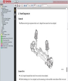 |
|||
|
Читать/Скачать
|
||||
| Мануал по ремонту Celica T23 на Русском. | ||||
| В руководстве дается пошаговое описание процедур по эксплуатации, техническому обслуживанию и ремонту леворульных и праворульных переднеприводных автомобилей Toyota Celica выпуска с 1999 г., оборудованных бензиновыми двигателями 1ZZ-FE (1,8 л.) и 2ZZ-GE (1,8 л.). Издание содержит подробные сведения по проверке элементов системы управления бензиновыми двигателями, системы изменения фаз газораспределения (VVTL), смазки, охлаждения, запуска и зарядки. Приведены инструкции по использованию системы самодиагностики двигателя, АКПП, ABS, SRS и рекомендации по регулировке и ремонту двигателей, механических и автоматических коробок передач, элементов тормозной системы (включая ABS), системы пассивной безопасности (SRS), рулевого управления и подвески. Представлены подробные электросхемы и описания проверок элементов электрооборудования. Приведены возможные неисправности и методы их устранения, сопрягаемые размеры основных деталей и пределы их допустимого износа, рекомендуемые смазочные материалы и рабочие жидкости. Книга предназначена для автовладельцев, персонала СТО и ремонтных мастерских. |
 |
|||
|
Читать/Скачать |
||||
| Мануал по ремонту Celica T20 | ||||
|
В руководстве дается пошаговое описание процедур по эксплуатации, |
|
|||
|
Читать/Скачать
|
||||
| Оригинальный мануал по ремонту Celica T23 ENG. | ||||
| В руководстве дается описание процедур по эксплуатации, техническому обслуживанию и ремонту автомобилей Toyota Celica Т23 выпуска с 1999 г., оборудованных двигателями 1ZZ-FE и 2ZZ-GE. Издание содержит подробные сведения по проверке элементов системы управления двигателями, системе VVTL, смазки, охлаждения, запуска и зарядки. Приведены инструкции по использованию системы самодиагностики двигателя, АКПП, ABS, SRS и рекомендации по регулировке и ремонту двигателей, механических и автоматических коробок передач, элементов тормозной системы (включая ABS), системы пассивной безопасности (SRS), рулевого управления и подвески. Книга предназначена для автовладельцев, персонала СТО и ремонтных мастерских. |
 |
|||
|
Читать/Скачать |
||||
| Toyota Celica 4WD ST205. Repair Manual supplement for chassis & body | ||||
| Руководство по ремонту кузова и шасси Toyota Celica 4WD серии ST205. Информацияпредставленная в данном издании действительна на момент публикации. Вместе с тем технические характеристики и процедуры могут быть изменены без предварительного уведомления. |  |
|||
|
Читать/Скачать |
||||
|
Руководство по ремонту и эксплуатации Toyota Celica Supra MK2-8 |
||||
| Рассмотрены все модели 2-го поколения Celica / Supra MK2 и все двигатели, ставившиеся на этот автомобиль: DOHC 2.8L 5M-GE (для США), 5M-E (для Швеции, Швейцарии и Австралии), турбированные SOHC M-TE и 2-литровый twinturbo 1G-GTE (для Японии). Также в Японии машина комплектовалась двигателем 1G-GEU и продавалась под названием Celica XX. |  |
|||
|
Читать/Скачать |
||||
|
Руководство по ремонту и эксплуатации Toyota Celica Supra MK3-90 |
||||
|
||||
| Toyota 3S-GE engine Repair Manual | ||||
|
Руководство по ремонту двигателей Toyota 3S-GE для автомобилей Toyota Celica ST202 (сентябрь 1993 — декабрь 1997) и Toyota MR2 SW20 (ноябрь 1993 — декабрь 1997). Информация предоставленная в данном издании действительна на момент публикации. Вместе с тем технические характеристики и процедуры могут быть изменены без предварительного уведомления. |
 |
|||
|
Читать/Скачать |
||||
| Toyota 3S-GTE engine Repair Manual supplement | ||||
| Руководство по ремонту двигателей Toyota 3S-GTE. Информация, предоставленная в данном издании действительна на момент публикации. Вместе с тем технические характеристики и процедуры могут быть изменены без предварительного уведомления. |  |
|||
|
Читать/Скачать |


|
Toyota 3S-FE Engine Repair Manual |
|
|
Двигателья Toyota 3S-FE Инструкция по ремонту двигателя для автомобилей выпущенных с Oct. 1997 по Dec. 2002. The Toyota 3S-FE is a 16-valve 2.0L twin camshaft, single cam gear engine built by Toyota from 1986 to 2000. European version produces 128 PS (94 kW)(126 hp) at 5,600 rpm and 179 Nm (132 ft-lbs) at 4,400 rpm. It is commonly used in the
|
 |
|
Читать/Скачать |