Не можете найти ответ на свой вопрос в руководстве? Вы можете найти ответ на свой вопрос ниже, в разделе часто задаваемых вопросов о Yamaha FJR1300AS (2016).
Как перевести мили в километры?
В чем разница между топливом E10 и E5?
Какова рекомендуемая частота замены масляного фильтра в двигателе Yamaha?
Как часто следует менять масло в двигателе Yamaha?
Как удалить ржавчину с устройства Yamaha Мотоцикл?
Инструкция Yamaha FJR1300AS (2016) доступно в русский?
Не нашли свой вопрос? Задайте свой вопрос здесь
- Manuals
- Brands
- Yamaha Manuals
- Motorcycle
- FJR1300A(D)
- Service manual
-
Contents
-
Table of Contents
-
Troubleshooting
-
Bookmarks
Related Manuals for Yamaha FJR1300A(D)
Summary of Contents for Yamaha FJR1300A(D)
-
Page 1
2013 SERVICE MANUAL FJR1300A(D) 1MC-28197-E0… -
Page 2
EAS20040 FJR1300A(D) 2013 SERVICE MANUAL ©2012 by Yamaha Motor Co., Ltd. First edition, August 2012 All rights reserved. Any reproduction or unauthorized use without the written permission of Yamaha Motor Co., Ltd. is expressly prohibited. -
Page 3
EAS20071 IMPORTANT This manual was produced by the Yamaha Motor Company, Ltd. primarily for use by Yamaha dealers and their qualified mechanics. It is not possible to include all the knowledge of a mechanic in one man- ual. Therefore, anyone who uses this book to perform maintenance and repairs on Yamaha vehicles should have a basic understanding of mechanics and the techniques to repair these types of vehicles. -
Page 4: How To Use This Manual
EAS20090 HOW TO USE THIS MANUAL This manual is intended as a handy, easy-to-read reference book for the mechanic. Comprehensive explanations of all installation, removal, disassembly, assembly, repair and check procedures are laid out with the individual steps in sequential order. •…
-
Page 5: Symbols
EAS20101 SYMBOLS The following symbols are used in this manual for easier understanding. The following symbols are not relevant to every vehicle. SYMBOL DEFINITION SYMBOL DEFINITION Serviceable with engine mounted Gear oil Filling fluid Molybdenum disulfide oil Lubricant Brake fluid Special tool Wheel bearing grease Tightening torque…
-
Page 7: Table Of Contents
EAS20110 TABLE OF CONTENTS GENERAL INFORMATION SPECIFICATIONS PERIODIC CHECKS AND ADJUSTMENTS CHASSIS ENGINE COOLING SYSTEM FUEL SYSTEM ELECTRICAL SYSTEM TROUBLESHOOTING…
-
Page 9: General Information
MODEL LABEL………………1-1 FEATURES…………………. 1-2 OUTLINE OF THE FI SYSTEM…………..1-2 FI SYSTEM………………..1-3 YCC-T (Yamaha Chip Controlled Throttle)……….1-4 OUTLINE OF THE CRUISE CONTROL SYSTEM……..1-6 OUTLINE OF THE UNIFIED BRAKE SYSTEM ……..1-13 OUTLINE OF THE ABS…………….1-15 ABS COMPONENT FUNCTIONS …………1-19 ABS OPERATION ……………….1-25…
-
Page 10: Identification
IDENTIFICATION EAS20130 IDENTIFICATION EAS20140 VEHICLE IDENTIFICATION NUMBER The vehicle identification number “1” is stamped into the right side of the steering head pipe. EAS20150 MODEL LABEL The model label “1” is affixed to the frame. This information will be needed to order spare parts.
-
Page 11: Features
FEATURES EAS20170 FEATURES ET2C01025 OUTLINE OF THE FI SYSTEM The main function of a fuel supply system is to provide fuel to the combustion chamber at the optimum air-fuel ratio in accordance with the engine operating conditions and the atmospheric temperature. In the conventional carburetor system, the air-fuel ratio of the mixture that is supplied to the combustion chamber is created by the volume of the intake air and the fuel that is metered by the jet used in the respective carburetor.
-
Page 12: Fi System
FEATURES ET3P61042 FI SYSTEM The fuel pump delivers fuel to the fuel injector via the fuel filter. The pressure regulator maintains the fuel pressure that is applied to the fuel injector at only 324 kPa (3.24 kg/cm², 47.0 psi). Accordingly, when the energizing signal from the ECU energizes the fuel injector, the fuel passage opens, causing the fuel to be injected into the intake manifold only during the time the passage remains open.
-
Page 13: Ycc-T (Yamaha Chip Controlled Throttle)
Yamaha developed the YCC-T system employing the most advanced electronic control technologies. Electronic control throttle systems have been used on automobiles, but Yamaha has developed a fast- er, more compact system specifically for the needs of a sports motorcycle. The Yamaha-developed system has a high-speed calculating capacity that produces computations of running conditions every 1/1000th of a second.
-
Page 14
FEATURES YCC-T system outline 1. Throttle position sensor 2. Throttle servo motor 3. Accelerator position sensor 4. ECU (engine control unit) 5. Sensor input 6. Gear position switch 7. Crankshaft position sensor 8. Rear wheel sensor 9. Coolant temperature sensor… -
Page 15: Outline Of The Cruise Control System
FEATURES EAS1MC1087 OUTLINE OF THE CRUISE CONTROL SYSTEM This model is equipped with a cruise control system designed to maintain a set cruising speed. Be- cause the vehicle is equipped with the YCC-T system, the cruise control system can be controlled elec- tronically.
-
Page 16
FEATURES EWA1MC1006 WARNING • Improper use of the cruise control system may result in loss of control, which could lead to an accident. Do not activate the cruise control system in heavy traffic, poor weather conditions, or among winding, slippery, hilly, rough or gravel roads. •… -
Page 17
FEATURES Deactivating the cruise control system Perform one of the following operations to cancel the set cruising speed. The cruise control setting in- dicator light “SET” will go off. • Turn the throttle grip past the closed position in the deceleration direction. •… -
Page 18
FEATURES Operation chart A. Operation a. Cruise control power switch “ ” “ON” B. Indication b. Manual acceleration C. Speed c. Push the “SET–” side of the cruise control setting switch D. 180 km/h (112 mph) d. Currently set cruising speed increases E. -
Page 19
Because the automatic deactivation of the cruise control system is stored in the memory of the ECU, the deactivation can be checked using the Yamaha diagnostic tool. In some cases, the cruise control system may not be able to maintain the set cruising speed when the vehicle is traveling uphill or downhill. -
Page 20
FEATURES Meter displays during cruise control system operation A. Cruise control system is activated (cruising a. Condition for automatically deactivating cruise speed is set) control system is detected B. Cruise control system is turned off (cruise b. 4 seconds elapse (during this time, input from control system indicator light “… -
Page 21
FEATURES • If the cruise control system turned off because a malfunction was detected by the FI self-diagnosis, the cruise control power switch “ ” must be pushed once before the system can return to the normal operating condition. • If a switch for the cruise control system is malfunctioning (fault code No. 90 and 91), the engine trouble warning light will not come on because the normal operation of the vehicle is not affected. -
Page 22: Outline Of The Unified Brake System
OUTLINE OF THE UNIFIED BRAKE SYSTEM The Yamaha unified brake system is a system that operates one set of pistons in the front brakes to- gether with the rear brake when the brake pedal is depressed. Compared to conventional brake sys- tems, the ability to slow the vehicle using the simple operation of the brake pedal is improved.
-
Page 23
FEATURES Brake pedal input force and braking force at each wheel a. Brake force e. Proportioning valve operation b. Brake pedal force f. Metering valve operation c. Rear brake force d. Front brake force (unified brake system) Metering valve This valve prevents the brake fluid pressure that is transmitted to the right front brake caliper from in- creasing until the pressure exceeds a set level. -
Page 24: Outline Of The Abs
8. Rear wheel sensor The operation of the Yamaha ABS brakes is the same as conventional brakes on other vehicles, with a brake lever for operating the front brake and a brake pedal for operating the rear brake. However, part of the front brake is operated together with rear brake.
-
Page 25
FEATURES When the brakes are applied, wheel speed and chassis speed are reduced. However, the chassis travels forward by its inertia even though the wheel speed is reduced. • Brake force: The force applied by braking to reduce the wheel speed. •… -
Page 26
FEATURES Wheel slip and hydraulic control The ABS ECU calculates the wheel speed of each wheel according to the rotation signal received from the front and rear wheel sensors. In addition, the ABS ECU calculates the vehicle chassis speed and the rate of speed reduction based on the wheel speed values. -
Page 27
Slip ratio (%) b. Brake force Electronic ABS features The Yamaha ABS (anti-lock brake system) has been developed with the most advanced electronic technology. The ABS control is processed with good response under various vehicle travel conditions. The ABS also includes a highly developed self-diagnosis function. The ABS detects any problem con- dition and allows normal braking even if the ABS is not operating properly. -
Page 28: Abs Component Functions
FEATURES ABS block diagram 1. Rear brake master cylinder 10. Proportioning valve 2. Hydraulic unit assembly 11. Rear brake caliper 3. Front brake master cylinder 12. Rear wheel sensor 4. Inlet solenoid valve 13. Metering valve 5. ABS motor 14. ABS warning light 6.
-
Page 29
FEATURES 3. At low speed 7. Voltage 4. At high speed 8. Time 5. Wheel sensor 6. Wheel sensor rotor ABS warning light The ABS warning light “1” comes on to warn the rider if a malfunction in the ABS occurs. When the main switch is turned to “ON”, the ABS warning light comes on during the ABS self-diagnosis to check the electrical circuit of the light. -
Page 30
FEATURES GEAR A.TEMP ˚C C.TEMP ˚C TIME TRIP 0:06 • Hydraulic unit assembly The hydraulic unit assembly “1” is composed of hydraulic control valves (each with a outlet solenoid valve and inlet solenoid valve), buffer chambers, hydraulic pumps, an ABS motor, and ABS ECU. The hydraulic unit adjusts the front and rear wheel brake fluid pressure to control the wheel speed accord- ing to signals transmitted from the ABS ECU. -
Page 31
FEATURES 3. When the ABS ECU sends a signal to stop reducing the hydraulic pressure, the outlet solenoid valve “2” closes and the brake fluid is pressurized again. The inlet solenoid valve “1” controls the hydraulic pressure difference between the brake fluid in the upper brake lines (brake master cylin- der side) and the brake fluid in the lower brake lines (brake caliper side). -
Page 32
FEATURES • ABS ECU The ABS ECU is integrated with the hydraulic unit to achieve a compact and lightweight design. As shown in the block following diagram, the ABS ECU receives wheel sensor signals from the front and rear wheels and also receives signals from other monitor circuits. 20 21 24 25 1. -
Page 33
FEATURES ABS control operation The ABS control operation performed in the ABS ECU is divided into the following two parts. • Hydraulic control • Self-diagnosis When a malfunction is detected in the ABS, a fault code is stored in the memory of the ABS ECU for easy problem identification and troubleshooting. -
Page 34: Abs Operation
FEATURES ET3P61052 ABS OPERATION The ABS hydraulic circuit consists of two systems: the front wheel, and rear wheel. The following de- scribes the system for the front wheel only, excluding the unified brake system. Normal braking (ABS not activated) When the ABS is not activated, the inlet solenoid valve is open and the outlet solenoid valve is closed because a control signal has not been transmitted from the ABS ECU.
-
Page 35
FEATURES Emergency braking (ABS activated) 1. Depressurizing phase When the front wheel is about to lock, the outlet solenoid valve is opened by the “depressurization” signal transmitted from the ABS ECU. When this occurs, the inlet solenoid valve compresses the spring and closes the brake line from the brake master cylinder. -
Page 36
FEATURES 2. Pressurizing phase The outlet solenoid valve is closed by the “pressurization” signal transmitted from the ABS ECU. At this time, the ABS ECU controls the opening of the inlet solenoid valve. As the inlet solenoid valve opens, the brake line from the brake master cylinder opens, allowing the brake fluid to be sent to the brake caliper. -
Page 37: Abs Self-Diagnosis Function
FEATURES ET3P61053 ABS SELF-DIAGNOSIS FUNCTION ABS warning light The ABS warning light “1” comes on when a malfunction is detected by the ABS self-diagnosis. It is located in the multi-function meter center display. GEAR A.TEMP ˚C C.TEMP ˚C TIME TRIP 0:06 Instances when the ABS warning light comes on 1.
-
Page 38
FEATURES 2. The ABS warning light comes on while the “ ” side of the start/engine stop switch is being pushed. When the engine is being started, the ABS warning light comes on while the “ ” side of the start/en- gine stop switch is being pushed. -
Page 39
FEATURES a. ABS warning light d. Unstable ABS ECU input b. Comes on c. Goes off 5. The ABS warning light “1” flashes and a fault code “2” is indicated on the multi-function meter right display when the test coupler adapter “3” is connected to the ABS test coupler “4” for troubleshooting the ABS. -
Page 40: Abs Warning Light And Operation
FEATURES ET3P61054 ABS WARNING LIGHT AND OPERATION ABS and UBS function EWA1MC1024 WARNING • When hydraulic control is performed by the ABS, the brake system alerts the rider that the wheels have a tendency to lock by generating a reaction-force pulsating action in the brake lever or brake pedal.
-
Page 41: Outline Of The Tcs (Traction Control System)
FEATURES EAS1MC1082 OUTLINE OF THE TCS (Traction Control System) The traction control system controls excessive spinning (slipping) of the rear wheel when accelerating on slippery surfaces, such as unpaved or wet roads. The ECU monitors the front and rear wheel speeds using the signals from the front and rear wheel sen- sors, and detects rear wheel slipping according to the difference between the wheel speeds.
-
Page 42
FEATURES 1. Front wheel sensor A. Signal conversion 2. Rear wheel sensor B. Slip amount calculation 3. ABS ECU (electronic control unit) C. Exceeds preset value 4. “TCS” button D. Actuator control 5. ECU (engine control unit) E. Fuel cut-off F. -
Page 43
FEATURES Turn the traction control system off to help free the rear wheel if the motorcycle gets stuck in mud, sand, or other soft surfaces. ECA1MC1014 NOTICE Use only the specified tires. Using different sized tires will prevent the traction control system from controlling tire rotation accurately. -
Page 44: Multi-Function Meter Unit
FEATURES • a clock EAS1MC1030 MULTI-FUNCTION METER UNIT • a fuel meter • a transmission gear display 9 10 • a drive mode display (which shows the select- ed drive mode) • a function display (which shows the selected function) GEAR •…
-
Page 45
FEATURES Fuel meter • Select the transmission gear that is appropri- ate for the vehicle speed. Transmission gear display GEAR A.TEMP GEAR C.TEMP A.TEMP ˚C C.TEMP ˚C 1. Fuel meter TIME TRIP 0:06 The fuel meter indicates the amount of fuel in the fuel tank. -
Page 46
FEATURES Function display Selecting the information display GEAR TRIP-1 TRIP-2 GEAR GEAR GEAR A.TEMP ˚C A.TEMP ˚C RANGE C.TEMP ˚C C.TEMP ˚C FUEL AVG km/L 12.3 TIME TRIP 0:06 TIME TRIP FUEL CRNT km/L 0:06 12.3 1. Function display 1. Information display 2. -
Page 47
FEATURES Tripmeter displays: itself automatically and the display will return to the prior mode after refueling and traveling 5 km (3 mi). Estimated traveling range display: TRIP-1 RANGE The distance that can be traveled with the re- TRIP-2 maining fuel in the fuel tank under the current riding conditions is shown. -
Page 48
FEATURES This display shows the ambient temperature Average fuel consumption display: from –9 °C to 50 °C in 1 °C increments. The tem- perature displayed may vary from the ambient temperature. FUEL AVG km/L • –9 °C will be displayed even if the ambient tem- 12.3 perature falls below –9 °C. -
Page 49
FEATURES • The “L/100km” display shows the amount of This function allows you to fuel necessary to travel 100 km. check and reset the “TIME- • For the UK only: The “MPG” display shows the 2” and “TIME-3” functions. These time trips show the to- distance that can be traveled on 1.0 Imp.gal of tal elapsed time that the fuel. -
Page 50
FEATURES 2. Push the menu switch “MENU”. The grip Resetting the maintenance counters warmer setting display will be shown and 1. Use the select switch to highlight “Mainte- “High” will flash in the display. nance”. Grip Warmer MENU Grip Warmer Hi g h Maintenance Time Trip… -
Page 51
FEATURES 2. Push the menu switch “MENU” to display 3. Push the menu switch “MENU”. “km” or “mile” “TIME-2” and “TIME-3”. To reset a time trip, will flash in the display. push the “RESET” button to select the item to 4. -
Page 52
FEATURES 2. Push the menu switch “MENU”, use the se- 5. When you are finished changing the settings, lect switch to highlight the display to change, use the select switch to highlight “ ”, and and then push the menu switch “MENU” then push the menu switch “MENU”… -
Page 53
FEATURES Setting the clock 2. Push the menu switch “MENU”. 1. Use the select switch to highlight “Clock”. 3. Use the select switch to highlight “YES”, and then push the menu switch “MENU”. MENU Grip Warmer All Reset Maintenance Time Trip Unit Display Brightness… -
Page 54
FEATURES 1. Use the code re-registering key to start the Touring mode “T” engine. The touring mode “T” is suitable for various riding conditions. This mode allows the rider to enjoy smooth driv- Make sure there are no other immobilizer keys ability from the low-speed range to the high- close to the main switch, and do not keep more speed range. -
Page 55: Important Information
5. Keep all parts away from any source of fire. EAS20200 REPLACEMENT PARTS Use only genuine Yamaha parts for all replace- ments. Use oil and grease recommended by Yamaha for all lubrication jobs. Other brands may be similar in function and appearance, but inferior in quality.
-
Page 56: Bearings And Oil Seals
IMPORTANT INFORMATION EAS20230 EAS1MC1085 BEARINGS AND OIL SEALS RUBBER PARTS Install bearings “1” and oil seals “2” so that the Check rubber parts for deterioration during in- manufacturer’s marks or numbers are visible. spection. Some of the rubber parts are sensitive When installing oil seals, lubricate the oil seal to gasoline, flammable oil, grease, etc.
-
Page 57: Basic Service Information
BASIC SERVICE INFORMATION EAS30380 BASIC SERVICE INFORMATION EAS30390 QUICK FASTENERS Rivet type 1. Remove: • Quick fastener To remove the quick fastener, push its pin with a screwdriver, then pull the fastener out. Screw type 1. Remove: • Quick fastener To remove the quick fastener, loosen the screw with a screwdriver, then pull the fastener out.
-
Page 58: Electrical System
BASIC SERVICE INFORMATION ECA16760 EAS30402 NOTICE ELECTRICAL SYSTEM Be sure to connect the battery leads to the correct battery terminals. Reversing the bat- Electrical parts handling tery lead connections could damage the ECA16600 NOTICE electrical components. Never disconnect a battery lead while the en- gine is running;…
-
Page 59
BASIC SERVICE INFORMATION ECA16620 Checking the electrical system NOTICE Handle electrical components with special Before checking the electrical system, make care, and do not subject them to strong sure that the battery voltage is at least 12 V. shocks. ECA14371 ECA16630 NOTICE NOTICE… -
Page 60
BASIC SERVICE INFORMATION 2. Check: Checking the connections • Lead Check the leads, couplers, and connectors for • Coupler stains, rust, moisture, etc. • Connector 1. Disconnect: Moisture → Dry with an air blower. • Lead Rust/stains → Connect and disconnect sev- •… -
Page 61
BASIC SERVICE INFORMATION The resistance values shown were obtained at the standard measuring temperature of 20 °C (68 °F). If the measuring temperature is not 20 °C (68 °F), the specified measuring conditions will be shown. Intake air temperature sensor re- sistance 5.40–6.60 kΩ… -
Page 62: Special Tools
SPECIAL TOOLS EAS20260 SPECIAL TOOLS The following special tools are necessary for complete and accurate tune-up and assembly. Use only the appropriate special tools as this will help prevent damage caused by the use of inappropriate tools or improvised techniques. Special tools, part numbers or both may differ depending on the country. When placing an order, refer to the list provided below to avoid any mistakes.
-
Page 63
SPECIAL TOOLS Reference Tool name/Tool No. Illustration pages Steering nut wrench 3-19, 4-96 90890-01403 Exhaust flange nut wrench YU-A9472 Oil filter wrench 3-24 90890-01426 YU-38411 Oil pressure gauge set 3-26 90890-03120 Oil pressure adapter B 3-26 90890-03124 Hexagon wrench (41) 4-33, 4-35 90890-01525 YM-01525… -
Page 64
SPECIAL TOOLS Reference Tool name/Tool No. Illustration pages Final gear backlash band 4-113 90890-01511 Middle drive gear lash tool YM-01230 Coupling gear/middle shaft tool 4-115, 4-118 90890-01229 Gear holder YM-01229 Bearing retainer wrench 4-115, 4-118 90890-04050 Pinion bearing retainer & remover YM-04050 Fork seal driver weight 4-120… -
Page 65
Pivot shaft wrench adapter 5-8, 5-9 90890-01476 Rotor holding tool 5-13, 5-16 90890-01235 Universal magneto & rotor holder YU-01235 Yamaha bond No. 1215 5-18, 5-34, 90890-85505 5-37, 5-82, (Three Bond No.1215®) 6-13 Valve spring compressor 5-24, 5-29 90890-04019 YM-04019… -
Page 66
SPECIAL TOOLS Reference Tool name/Tool No. Illustration pages Sheave holder 5-33, 5-34, 90890-01701 5-37 Primary clutch holder YS-01880-A Flywheel puller 5-33 90890-01362 Heavy duty puller YU-33270-B Universal clutch holder 5-49, 5-52 90890-04086 YM-91042 Thickness gauge 5-50 90890-03180 Feeler gauge set YU-26900-9 Bearing retainer wrench 5-69, 5-71… -
Page 67
SPECIAL TOOLS Reference Tool name/Tool No. Illustration pages Piston pin puller set 5-86 90890-01304 Piston pin puller YU-01304 YU-01304 Piston ring compressor 5-91 90890-05158 YM-08037 Slide hammer bolt 5-102 90890-01083 Slide hammer bolt 6 mm YU-01083-1 Weight 5-102 90890-01084 YU-01083-3 YU-01083-3 Radiator cap tester 90890-01325… -
Page 68
Middle drive bearing installer 40 & 50 mm YM-04058 Pressure gauge 7-10 90890-03153 YU-03153 Fuel injector pressure adapter 7-10 90890-03210 YU-03210 Fuel pressure adapter 7-10 90890-03176 YM-03176 Yamaha diagnostic tool 8-38 90890-03215 Ignition checker 8-182 90890-06754 Oppama pet-4000 spark checker YM-34487 1-59… -
Page 69
SPECIAL TOOLS Reference Tool name/Tool No. Illustration pages Test harness-lean angle sensor (6P) 8-183 90890-03209 YU-03209 Digital circuit tester 8-184, 8-190 90890-03174 Model 88 Multimeter with tachometer YU-A1927 Test harness- speed sensor (3P) 8-189 90890-03208 YU-03208 Test harness S- pressure sensor (3P) 8-190 90890-03207 YU-03207… -
Page 70
SPECIAL TOOLS 1-61… -
Page 71: Specifications
SPECIFICATIONS GENERAL SPECIFICATIONS ……………. 2-1 ENGINE SPECIFICATIONS …………….2-2 CHASSIS SPECIFICATIONS …………….2-10 ELECTRICAL SPECIFICATIONS …………..2-13 TIGHTENING TORQUES …………….2-16 GENERAL TIGHTENING TORQUE SPECIFICATIONS……2-16 ENGINE TIGHTENING TORQUES…………2-17 CHASSIS TIGHTENING TORQUES…………2-22 LUBRICATION POINTS AND LUBRICANT TYPES ……..2-27 ENGINE………………..2-27 CHASSIS………………..2-29 LUBRICATION SYSTEM CHART AND DIAGRAMS……..
-
Page 72: General Specifications
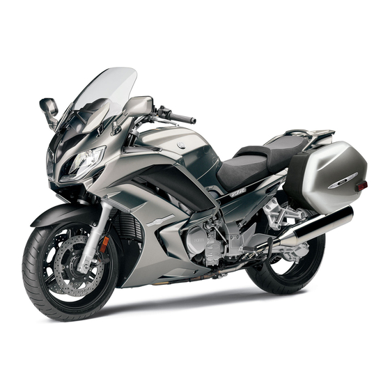
GENERAL SPECIFICATIONS EAS20280 GENERAL SPECIFICATIONS Model Model 1MC1 (Europe except (F)) 1MC2 (B) (F) 1MC6 (AUS) Dimensions Overall length 2230 mm (87.8 in) Overall width 750 mm (29.5 in) Overall height 1325/1455 mm (52.2/57.3 in) Seat height 805/825 mm (31.7/32.5 in) Wheelbase 1545 mm (60.8 in) Ground clearance…
-
Page 73: Engine Specifications
ENGINE SPECIFICATIONS EAS20290 ENGINE SPECIFICATIONS Engine Engine type Liquid cooled 4-stroke, DOHC Displacement 1298.0 cm³ Cylinder arrangement Inline 4-cylinder Bore × stroke 79.0 × 66.2 mm (3.11 × 2.61 in) Compression ratio 10.80 : 1 Standard compression pressure (at sea level) 1600 kPa/400 r/min (16.0 kgf/cm²/400 r/min, 227.6 psi/400 r/min) Minimum-maximum…
-
Page 74
ENGINE SPECIFICATIONS Bypass valve opening pressure 78.4–117.6 kPa (0.78–1.18 kgf/cm², 11.4–17.1 psi) Relief valve operating pressure 480.0–560.0 kPa (4.80–5.60 kgf/cm², 69.6–81.2 psi) Cooling system Radiator capacity (including all routes) 2.60 L (2.75 US qt, 2.29 Imp.qt) Radiator capacity 0.65 L (0.69 US qt, 0.57 Imp.qt) Coolant reservoir capacity (up to the maximum level mark) 0.25 L (0.26 US qt, 0.22 Imp.qt) -
Page 75
ENGINE SPECIFICATIONS Limit 24.897 mm (0.9802 in) Camshaft runout limit 0.030 mm (0.0012 in) Timing chain Tensioning system Automatic Valve, valve seat, valve guide Valve clearance (cold) Intake 0.15–0.22 mm (0.0059–0.0087 in) Exhaust 0.18–0.25 mm (0.0071–0.0098 in) Valve dimensions Valve head diameter A (intake) 29.90–30.10 mm (1.1772–1.1850 in) Valve head diameter A (exhaust) 25.90–26.10 mm (1.0197–1.0276 in) -
Page 76
ENGINE SPECIFICATIONS Limit 0.105 mm (0.0041 in) Valve stem runout 0.010 mm (0.0004 in) Cylinder head valve seat width (intake) 0.90–1.10 mm (0.0354–0.0433 in) Cylinder head valve seat width (exhaust) 0.90–1.10 mm (0.0354–0.0433 in) Valve spring Free length (intake) 39.73 mm (1.56 in) Limit 37.74 mm (1.49 in) Free length (exhaust) -
Page 77
ENGINE SPECIFICATIONS Height H 5.0 mm (0.20 in) Offset 0.50 mm (0.0197 in) Offset direction Intake side Piston pin bore inside diameter 19.004–19.015 mm (0.7482–0.7486 in) Limit 19.045 mm (0.7498 in) Piston pin outside diameter 18.991–19.000 mm (0.7477–0.7480 in) Limit 18.971 mm (0.7469 in) Piston-pin-to-piston-pin-bore clearance 0.004–0.024 mm (0.00016–0.00094 in) -
Page 78
ENGINE SPECIFICATIONS Crankshaft Width A 61.60–63.20 mm (2.425–2.488 in) Width B 325.10–326.30 mm (12.80–12.85 in) Runout limit C 0.030 mm (0.0012 in) Big end side clearance D 0.160–0.262 mm (0.0063–0.0103 in) Journal oil clearance 0.027–0.045 mm (0.0011–0.0018 in) Bearing color code 2.Black 3.Brown 4.Green 5.Yellow 6.Pink 7.Red 8.White Balancer… -
Page 79
ENGINE SPECIFICATIONS Shifting mechanism Shift mechanism type Shift drum and guide bar Shift fork guide bar bending limit 0.100 mm (0.0039 in) Air filter Air filter element Dry element Fuel pump Pump type Electrical Maximum consumption amperage 6.0 A Fuel injector Model/quantity 0990/4 12.0 Ω… -
Page 80
ENGINE SPECIFICATIONS Ring-gear-to-stopper-bolt clearance 0.30–0.60 mm (0.0118–0.0236 in) Ring-gear-to-thrust-washer clearance 0.20 mm (0.0079 in) Final gear backlash 0.22–0.45 mm (0.0087–0.0177 in) -
Page 81: Chassis Specifications
CHASSIS SPECIFICATIONS EAS20300 CHASSIS SPECIFICATIONS Chassis Frame type Diamond Caster angle 26.00° Trail 109.0 mm (4.29 in) Front wheel Wheel type Cast wheel 17M/C × MT3.50 Rim size Rim material Aluminum Wheel travel 135.0 mm (5.31 in) Radial wheel runout limit 1.0 mm (0.04 in) Lateral wheel runout limit 0.5 mm (0.02 in)
-
Page 82
CHASSIS SPECIFICATIONS Operation Right hand operation Front disc brake Disc outside diameter × thickness 320.0 × 4.5 mm (12.60 × 0.18 in) Brake disc thickness limit 4.0 mm (0.16 in) Brake disc deflection limit 0.10 mm (0.0039 in) Brake pad lining thickness (inner) 5.5 mm (0.22 in) Limit 0.5 mm (0.02 in) -
Page 83
CHASSIS SPECIFICATIONS Spring stroke K1 0.0–67.5 mm (0.00–2.66 in) Spring stroke K2 67.5–135.0 mm (2.66–5.31 in) Inner tube outer diameter 48.0 mm (1.89 in) Inner tube bending limit 0.2 mm (0.01 in) Optional spring available Recommended oil Suspension oil M1 or equivalent Quantity 716.0 cm³… -
Page 84: Electrical Specifications
ELECTRICAL SPECIFICATIONS EAS20310 ELECTRICAL SPECIFICATIONS Voltage System voltage 12 V Ignition system Ignition system Ignition timing (B.T.D.C.) 5.0°/1050 r/min Engine control unit Model/manufacturer TBDFE3/DENSO (Europe except (F)) (AUS) TBDFH3/DENSO (B) (F) Ignition coil Minimum ignition spark gap 6.0 mm (0.24 in) 1.19–1.61 Ω…
-
Page 85
ELECTRICAL SPECIFICATIONS Engine trouble warning light ABS warning light Cruise control system indicator light Cruise control setting indicator light Immobilizer system indicator light Traction control system indicator/warning light Electric starting system System type Constant mesh Starter motor Power output 0.80 kW 0.024–0.030 Ω… -
Page 86
ELECTRICAL SPECIFICATIONS Fuses Main fuse 50.0 A Cooling system fuse 30.0 A Headlight fuse 25.0 A Brake light fuse 1.0 A Signaling system fuse 10.0 A Ignition fuse 20.0 A 10.0 A × 2 Radiator fan fuse Auxiliary DC jack fuse 3.0 A Hazard lighting fuse 7.5 A… -
Page 87: Tightening Torques
TIGHTENING TORQUES EAS20320 TIGHTENING TORQUES EAS20330 GENERAL TIGHTENING TORQUE SPECIFICATIONS This chart specifies tightening torques for stan- dard fasteners with a standard ISO thread pitch. Tightening torque specifications for special com- ponents or assemblies are provided for each chapter of this manual. To avoid warpage, tight- en multi-fastener assemblies in a crisscross pat- tern and progressive stages until the specified tightening torque is reached.
-
Page 88: Engine Tightening Torques
TIGHTENING TORQUES EAS20340 ENGINE TIGHTENING TORQUES Thread Item Q’ty Tightening torque Remarks size Spark plug 13 Nm (1.3 m·kg, 9.4 ft·lb) Cylinder head bolt See TIP. Cylinder head bolt 12 Nm (1.2 m·kg, 8.7 ft·lb) Camshaft cap bolt 10 Nm (1.0 m·kg, 7.2 ft·lb) Cylinder head cover bolt 10 Nm (1.0 m·kg, 7.2 ft·lb) Cylinder head cover plate bolt…
-
Page 89
TIGHTENING TORQUES Thread Item Q’ty Tightening torque Remarks size Oil pan bolt 12 Nm (1.2 m·kg, 8.7 ft·lb) Oil pump drive chain guide bolt 12 Nm (1.2 m·kg, 8.7 ft·lb) Oil pump housing cover bolt 12 Nm (1.2 m·kg, 8.7 ft·lb) Oil level switch bolt 10 Nm (1.0 m·kg, 7.2 ft·lb) Throttle cable holder bolt… -
Page 90
TIGHTENING TORQUES Thread Item Q’ty Tightening torque Remarks size Upper crankcase damper bolt 12 Nm (1.2 m·kg, 8.7 ft·lb) Damper cover bolt (clutch cover) 12 Nm (1.2 m·kg, 8.7 ft·lb) Stator coil assembly lead holder 10 Nm (1.0 m·kg, 7.2 ft·lb) bolt Main gallery bolt 8 Nm (0.8 m·kg, 5.8 ft·lb) -
Page 91
TIGHTENING TORQUES Thread Item Q’ty Tightening torque Remarks size Radiator cover bolt 7 Nm (0.7 m·kg, 5.1 ft·lb) Radiator bracket bolt 10 Nm (1.0 m·kg, 7.2 ft·lb) Coolant reservoir bolt 7 Nm (0.7 m·kg, 5.1 ft·lb) Coolant reservoir bracket bolt 7 Nm (0.7 m·kg, 5.1 ft·lb) Cylinder head bolt Tighten the cylinder head bolts to 25 Nm (2.5 m·kg, 18 ft·lb) in the proper tightening sequence, loosen… -
Page 92
TIGHTENING TORQUES Crankcase tightening sequence: Middle gear case cover bolt Apply locking agent (LOCTITE®) only to the threads of the 2 upper middle gear case cover bolts, and then tighten all of the bolts to 12 Nm (1.2 m·kg, 8.7 ft·lb). 2-21… -
Page 93: Chassis Tightening Torques
TIGHTENING TORQUES EAS20350 CHASSIS TIGHTENING TORQUES Thread Item Q’ty Tightening torque Remarks size Engine mounting bolt (right front 49 Nm (4.9 m·kg, 35 ft·lb) lower side) Engine mounting bolt (right front 49 Nm (4.9 m·kg, 35 ft·lb) upper side) Engine mounting bolt (left front 49 Nm (4.9 m·kg, 35 ft·lb) lower side) Engine mounting bolt (left front…
-
Page 94
TIGHTENING TORQUES Thread Item Q’ty Tightening torque Remarks size Rear shock absorber spring pre- 7 Nm (0.7 m·kg, 5.1 ft·lb) load adjusting lever nut Upper bracket pinch bolt 26 Nm (2.6 m·kg, 19 ft·lb) Lower bracket pinch bolt 23 Nm (2.3 m·kg, 17 ft·lb) Steering stem nut 115 Nm (11.5 m·kg, 85 ft·lb) Lower ring nut… -
Page 95
TIGHTENING TORQUES Thread Item Q’ty Tightening torque Remarks size Rear upper fuel tank bracket and 16 Nm (1.6 m·kg, 11 ft·lb) rear lower fuel tank bracket nut Rear lower fuel tank bracket and 8 Nm (0.8 m·kg, 5.8 ft·lb) frame bolt Fuel tank cap bolt 6 Nm (0.6 m·kg, 4.3 ft·lb) Storage compartment bolt… -
Page 96
TIGHTENING TORQUES Thread Item Q’ty Tightening torque Remarks size Hydraulic unit assembly cap nut 16 Nm (1.6 m·kg, 11 ft·lb) Hydraulic unit assembly bracket 7 Nm (0.7 m·kg, 5.1 ft·lb) and hydraulic unit assembly bolt Metering valve bolt 7 Nm (0.7 m·kg, 5.1 ft·lb) Proportioning valve bolt 7 Nm (0.7 m·kg, 5.1 ft·lb) Sidestand nut… -
Page 97
TIGHTENING TORQUES Lower ring nut 1. First, tighten the lower ring nut to approximately 52 Nm (5.2 m·kg, 37 ft·lb) with a torque wrench, then loosen the lower ring nut completely. 2. Retighten the lower ring nut to 18 Nm (1.8 m·kg, 13 ft·lb) with a torque wrench. Brake hose joint bracket bolt To install the front brake hose joint, tighten the bolts in the proper tightening sequence. -
Page 98: Lubrication Points And Lubricant Types
LUBRICATION POINTS AND LUBRICANT TYPES EAS20360 LUBRICATION POINTS AND LUBRICANT TYPES EAS20370 ENGINE Lubrication point Lubricant Oil seal lips O-rings Bearings Crankshaft pins Piston surfaces Piston pins Connecting rod bolts and nuts Crankshaft journals Camshaft lobes Camshaft journals Balancer dampers, weights, gears and shafts Valve stems and stem end (intake and exhaust) Valve lifter surfaces Water pump impeller shaft…
-
Page 99
LUBRICATION POINTS AND LUBRICANT TYPES Lubrication point Lubricant Cylinder head cover mating surface Three Bond 1541C® Yamaha bond No.1215 Cylinder head cover gasket (Three Bond No.1215®) Yamaha bond No.1215 Crankcase mating surface (Three Bond No.1215®) Yamaha bond No.1215 Crankshaft position sensor lead grommet (Three Bond No.1215®) -
Page 100: Chassis
LUBRICATION POINTS AND LUBRICANT TYPES EAS20380 CHASSIS Lubrication point Lubricant Steering bearings and upper bearing cover lip Lower bearing dust seal lip Front wheel oil seal lip Rear wheel oil seal lip Rear wheel drive hub mating surface Rear brake pedal pivoting point Footrest assembly pivoting point Passenger footrest pivoting point Shift pedal pivoting point…
-
Page 101
LUBRICATION POINTS AND LUBRICANT TYPES 2-30… -
Page 102: Lubrication System Chart And Diagrams
LUBRICATION SYSTEM CHART AND DIAGRAMS EAS20390 LUBRICATION SYSTEM CHART AND DIAGRAMS EAS20400 ENGINE OIL LUBRICATION CHART 2-31…
-
Page 103
LUBRICATION SYSTEM CHART AND DIAGRAMS 1. Oil strainer 2. Oil pump 3. Relief valve assembly 4. Oil filter cartridge 5. Oil cooler 6. Main gallery 7. Front balancer shaft 8. Rear balancer shaft 9. Oil nozzle 10. Intake camshaft 11. Exhaust camshaft 12. -
Page 104: Lubrication Diagrams
LUBRICATION SYSTEM CHART AND DIAGRAMS EAS20410 LUBRICATION DIAGRAMS 2-33…
-
Page 105
LUBRICATION SYSTEM CHART AND DIAGRAMS 1. Intake camshaft 2. Cylinder head 3. Exhaust camshaft 4. Oil check bolt 5. Main gallery bolt 6. Crankshaft 7. Oil nozzle 2-34… -
Page 106
LUBRICATION SYSTEM CHART AND DIAGRAMS 2-35… -
Page 107
LUBRICATION SYSTEM CHART AND DIAGRAMS 1. Main axle 2. Drive axle 3. Oil delivery pipe 1 2-36… -
Page 108
LUBRICATION SYSTEM CHART AND DIAGRAMS 2-37… -
Page 109
LUBRICATION SYSTEM CHART AND DIAGRAMS 1. Oil check bolt 2. Crankshaft 3. Oil cooler 4. Oil strainer 5. Oil delivery pipe 3 6. Oil pump 2-38… -
Page 110
LUBRICATION SYSTEM CHART AND DIAGRAMS 2-39… -
Page 111
LUBRICATION SYSTEM CHART AND DIAGRAMS 1. Rear balancer 2. Oil delivery pipe 2 3. Engine oil drain bolt 4. Oil level switch 5. Crankshaft 6. Front balancer 7. Crank pin 8. Oil delivery pipe 3 9. Relief valve assembly 2-40… -
Page 112
LUBRICATION SYSTEM CHART AND DIAGRAMS 2-41… -
Page 113
LUBRICATION SYSTEM CHART AND DIAGRAMS 1. Oil strainer 2. Oil delivery pipe 2 3. Oil cooler 4. Engine oil drain bolt 5. Oil level switch 6. Oil filter cartridge 7. Oil delivery pipe 3 8. Oil pan 9. Oil pump 2-42… -
Page 114: Cooling System Diagrams
COOLING SYSTEM DIAGRAMS EAS20420 COOLING SYSTEM DIAGRAMS 2-43…
-
Page 115
COOLING SYSTEM DIAGRAMS 1. Thermostat inlet pipe 1 2. Thermostat inlet hose 1 3. Oil cooler outlet hose 4. Radiator 5. Coolant reservoir breather hose 6. Thermostat inlet pipe 2 7. Coolant reservoir hose 8. Radiator inlet hose 9. Thermostat inlet hose 2 10. -
Page 116
COOLING SYSTEM DIAGRAMS 2-45… -
Page 117
COOLING SYSTEM DIAGRAMS 1. Thermostat inlet pipe 1 2. Thermostat inlet hose 2 3. Radiator inlet hose 4. Radiator 5. Radiator outlet hose 6. Oil cooler outlet hose 7. Water jacket joint inlet hose 8. Water pump outlet pipe 9. Water pump outlet hose 10. -
Page 118: Cable Routing
CABLE ROUTING EAS20430 CABLE ROUTING Handlebar (front view) 2-47…
-
Page 119
CABLE ROUTING 1. Right grip warmer lead 2. Brake hose (front brake master cylinder to brake pipe/lower joint assembly) 3. Right handlebar switch lead 4. Clutch hose 5. Left handlebar switch lead 6. Clutch switch lead 7. Main switch lead 8. -
Page 120
CABLE ROUTING Radiator and battery (right side view) 2-49… -
Page 121
8. Radiator fan motor relay 9. Starter relay coupler 10. Front right turn signal light coupler 11. ABS test coupler lead 12. Yamaha diagnostic tool connector 13. Right radiator fan motor coupler 14. Negative battery lead 15. O sensor lead 16. -
Page 122
CABLE ROUTING Rear brake hose (right side view) 5 6 7 8 9 10 11 1 12 13 2-51… -
Page 123
CABLE ROUTING 1. Rear wheel sensor lead 2. Brake hose (rear brake master cylinder to brake pipe/middle joint assembly) 3. Rear brake fluid reservoir hose 4. Rear brake fluid reservoir 5. Brake pipe (hydraulic unit to metering valve) 6. Hydraulic unit assembly 7. -
Page 124
CABLE ROUTING Horn and radiator (left side view) 2-53… -
Page 125
CABLE ROUTING 1. Radiator inlet hose 2. Left radiator fan motor 3. Radiator 4. Coolant reservoir breather hose 5. Horn 6. Left radiator fan motor coupler 7. Left radiator fan motor lead 8. Coolant reservoir hose A. After connecting the left radiator fan motor coupler, position the coupler between the left side cowling and the left lower inner panel. -
Page 126
CABLE ROUTING Front brake hose and engine (left side view) 2-55… -
Page 127
CABLE ROUTING 1. Clutch hose Q. Route the front wheel sensor lead between the left front brake caliper and the brake hose (brake 2. AC magneto lead pipe/upper joint assembly to left front brake 3. Rectifier/regulator lead caliper). 4. Air filter case breather hose R. -
Page 128
CABLE ROUTING Rear fender (left side view) 2-57… -
Page 129
13. Rear brake light switch lead 14. Hydraulic unit assembly 15. Lean angle sensor 16. Yamaha diagnostic tool coupler A. Route the wire harness so that the joint couplers are positioned on top of the harness. B. Route the wire harness to the inside of the seat lock cable. -
Page 130
CABLE ROUTING Throttle bodies (top view) 2-59… -
Page 131
CABLE ROUTING 1. Ignition coil #1 coupler F. Install the positive battery lead terminal so that it is not positioned to the outside of the starter relay. 2. Clutch hose G. Install the starter motor lead terminal so that it is 3. -
Page 132
CABLE ROUTING Rear fender (top view) 2-61… -
Page 133
CABLE ROUTING 1. License plate light lead 2. Tail/brake light assembly lead 3. Seat lock cable A. Route the tail/brake light assembly lead and license plate light lead between the rib and the U- lock holder on the rear fender, making sure that the leads are not routed on top of the holder. -
Page 134
CABLE ROUTING Front cowling assembly and electrical components board 2-63… -
Page 135
CABLE ROUTING 1. Right headlight lead P. Insert the projection on right handlebar switch coupler completely into the hole in the electrical 2. Right auxiliary light lead components board. 3. Relay unit lead Q. Secure the holder by inserting the projection on 4. -
Page 136
CABLE ROUTING Hydraulic unit assembly (top and side view) 2-65… -
Page 137
CABLE ROUTING 1. Hydraulic unit assembly 2. Brake pipe/middle joint assembly 3. Brake pipe (hydraulic unit to metering valve) 4. Brake pipe (hydraulic unit to proportioning valve) 5. Brake pipe/upper joint assembly 6. Brake pipe/lower joint assembly 7. Brake pipe (proportioning valve to rear brake hose) 8. -
Page 138
CABLE ROUTING 2-67… -
Page 139: Periodic Checks And Adjustments
PERIODIC CHECKS AND ADJUSTMENTS PERIODIC MAINTENANCE …………….3-1 INTRODUCTION ………………3-1 PERIODIC MAINTENANCE CHART FOR THE EMISSION CONTROL SYSTEM …………….3-1 GENERAL MAINTENANCE AND LUBRICATION CHART …….3-1 CHECKING THE FUEL LINE …………..3-4 CHECKING THE SPARK PLUGS …………. 3-4 ADJUSTING THE VALVE CLEARANCE ……….3-5 CHECKING THE ENGINE IDLING SPEED ……….3-7 SYNCHRONIZING THE THROTTLE BODIES……….
-
Page 140
CHANGING THE COOLANT…………..3-27 CHECKING THE FINAL GEAR OIL LEVEL ……….3-29 CHANGING THE FINAL GEAR OIL…………3-29 CHECKING THE BRAKE LIGHT SWITCHES………3-30 ADJUSTING THE REAR BRAKE LIGHT SWITCH ………3-30 CHECKING AND LUBRICATING THE CABLES ……..3-30 CHECKING THE THROTTLE GRIP OPERATION ………3-31 CHECKING THE SWITCHES, LIGHTS AND SIGNALS …… -
Page 142: Periodic Maintenance
UK, a mileage-based maintenance, is performed instead. • From 50000 km (30000 mi), repeat the maintenance intervals starting from 10000 km (6000 mi). • Items marked with an asterisk should be performed by a Yamaha dealer as they require special tools, data and technical skills.
-
Page 143
PERIODIC MAINTENANCE ODOMETER READING CHECK OR MAINTENANCE ANNUAL ITEM 1000 km 10000 km 20000 km 30000 km 40000 km CHECK (600 mi) (6000 mi) (12000 mi) (18000 mi) (24000 mi) • Check for cracks or damage. √ √ √ √ √… -
Page 144
PERIODIC MAINTENANCE EAU17670 • The air filter needs more frequent service if you are riding in unusually wet or dusty areas. • Hydraulic brake and clutch service • Regularly check and, if necessary, correct the brake and clutch fluid levels. •… -
Page 145: Checking The Fuel Line
PERIODIC MAINTENANCE EAS21030 ECA13320 CHECKING THE FUEL LINE NOTICE 1. Remove: Before removing the spark plugs, blow away • Rider seat any dirt accumulated in the spark plug wells Refer to “GENERAL CHASSIS” on page 4-1. with compressed air to prevent it from falling •…
-
Page 146: Adjusting The Valve Clearance
PERIODIC MAINTENANCE 10.Install: Valve clearance (cold) • T-bar Intake Refer to “GENERAL CHASSIS” on page 4-1. 0.15–0.22 mm (0.0059–0.0087 in) • Fuel tank Exhaust Refer to “FUEL TANK” on page 7-1. 0.18–0.25 mm (0.0071–0.0098 in) • Rider seat Refer to “GENERAL CHASSIS” on page 4-1. ▼…
-
Page 147
PERIODIC MAINTENANCE • Measure the valve clearance in the following ▼ ▼▼▼ ▼ ▼▼▼ ▼ ▼ ▼▼▼ ▼ ▼ ▼▼▼ ▼ ▼ ▼▼▼ ▼ ▼ ▼▼▼ ▼ ▼▼▼ a. Remove the valve lifter “1” and the valve pad sequence. “2” with the valve lapper “3”. Valve clearance measuring sequence Valve lapper Cylinder #1 →… -
Page 148: Checking The Engine Idling Speed
PERIODIC MAINTENANCE Example: • Install the valve lifter and the valve pad in the If the valve pad is marked “155”, the pad correct place. thickness is 1.55 mm (0.061 in). g. Install the exhaust and intake camshafts, tim- d. Calculate the sum of the values obtained in ing chain and camshaft caps.
-
Page 149: Synchronizing The Throttle Bodies
▼ ▼ ▼▼▼ ▼ ▼ ▼▼▼ ▼ ▼▼▼ 4. Install: a. Connect the Yamaha diagnostic tool. • Vacuum gauge “1” Use the diagnostic code number “67”. Refer to “SELF-DIAGNOSTIC FUNCTION Vacuum gauge AND DIAGNOSTIC CODE TABLE” on page 90890-03094 9-5.
-
Page 150: Checking The Exhaust System
PERIODIC MAINTENANCE Adjusting the throttle body synchronization • The difference in vacuum pressure between 1. Remove the fuel tank bolts “1” and lift up the the throttle bodies should not exceed 1.33 kPa fuel tank. (10 mmHg). ECA1MC1024 NOTICE Carburetor angle driver 2 When lifting up the fuel tank, be careful not 90890-03173 to pull the fuel tank breather/overflow hose.
-
Page 151: Adjusting The Exhaust Gas Volume
PERIODIC MAINTENANCE • Exhaust pipe assembly bolts “6” • Exhaust pipe assembly and muffler bolts “7” • Muffler bolts “8” Exhaust pipe assembly nut DIAG 20 Nm (2.0 m·kg, 14 ft·lb) Exhaust pipe assembly bolt 17 Nm (1.7 m·kg, 12 ft·lb) Exhaust pipe assembly and muf- fler bolt 20 Nm (2.0 m·kg, 14 ft·lb)
-
Page 152: Checking The Air Induction System
PERIODIC MAINTENANCE 6. After selecting the cylinder number, simulta- ECA13450 NOTICE neously press the “TCS” button “1” and “RE- Make sure the crankcase breather hose is SET” button “2” for 2 seconds or more to routed correctly. execute the selection. 7.
-
Page 153: Adjusting The Clutch Lever
PERIODIC MAINTENANCE air filter element will also affect throttle body 2. Check: synchronization, leading to poor engine per- • Clutch fluid level Below the minimum level mark “a” → Add the formance and possible overheating. specified brake and clutch fluid to the proper 4.
-
Page 154: Adjusting The Front Disc Brake
PERIODIC MAINTENANCE Clutch release cylinder bleed • Be careful not to spill any clutch fluid or allow screw the clutch master cylinder reservoir to over- 5 Nm (0.5 m·kg, 3.6 ft·lb) flow. • When bleeding the hydraulic clutch system, k. Fill the clutch master cylinder reservoir to the make sure there is always enough clutch fluid proper level with the specified brake and before applying the clutch lever.
-
Page 155: Checking The Brake Fluid Level
PERIODIC MAINTENANCE ECA13490 EWA1MC1023 NOTICE WARNING • Use only the designated brake fluid. Other After adjusting the brake lever position, make sure there is no brake drag. brake fluids may cause the rubber seals to deteriorate, causing leakage and poor ▲…
-
Page 156
PERIODIC MAINTENANCE • Be careful not to spill any brake fluid or allow the brake master cylinder reservoir or brake fluid reservoir to overflow. • When bleeding the ABS, make sure that there is always enough brake fluid before applying the brake. -
Page 157: Checking The Front Brake Pads
PERIODIC MAINTENANCE EWA14020 WARNING After bleeding the ABS, check the brake op- eration. ▲ ▲▲▲ ▲ ▲▲▲ ▲ ▲ ▲▲▲ ▲ ▲ ▲▲▲ ▲ ▲ ▲▲▲ ▲ ▲ ▲▲▲ ▲ ▲▲▲ 3. Install: • Right side cover Refer to “GENERAL CHASSIS” on page 4-1. EAS21250 CHECKING THE FRONT BRAKE PADS 2.
-
Page 158: Checking The Rear Brake Pads
PERIODIC MAINTENANCE 1. Check: ECA13510 NOTICE • Wheel Damage/out-of-round → Replace. After adjusting the brake pedal position, make sure there is no brake drag. EWA13260 WARNING ▲ ▲▲▲ ▲ ▲▲▲ ▲ ▲ ▲▲▲ ▲ ▲ ▲▲▲ ▲ ▲ ▲▲▲ ▲ ▲…
-
Page 159
No guarantee con- cerning handling characteristics can be giv- 1. Tire tread depth en if a tire combination other than one 2. Side wall approved by Yamaha is used on this vehicle. 3. Wear indicator Front tire Wear limit (front) Size 1.6 mm (0.06 in) (Europe) -
Page 160: Checking The Wheel Bearings
PERIODIC MAINTENANCE Rear tire Recommended lubricant Size Lithium-soap-based grease 180/55 ZR17M/C (73W) Manufacturer/model Refer to “INSTALLING THE SWINGARM” on METZELER/Roadtec Z8 C page 4-104. BRIDGESTONE/BT023R F EAS21510 CHECKING AND ADJUSTING THE EWA13210 STEERING HEAD WARNING 1. Stand the vehicle on a level surface. New tires have a relatively low grip on the EWA13120 road surface until they have been slightly…
-
Page 161: Lubricating The Steering Head
PERIODIC MAINTENANCE 5. Install: • Upper bracket Set a torque wrench at a right angle to the steer- Refer to “STEERING HEAD” on page 4-94. ing nut wrench. EAS1MC1040 LUBRICATING THE STEERING HEAD 1. Lubricate: • Upper bearing • Lower bearing •…
-
Page 162: Checking The Centerstand
PERIODIC MAINTENANCE EAS1MC1043 EAS21580 CHECKING THE CENTERSTAND ADJUSTING THE FRONT FORK LEGS 1. Check: The following procedure applies to both of the • Centerstand operation front fork legs. Check that the centerstand moves smoothly. EWA13120 WARNING Rough movement → Repair or replace. Securely support the vehicle so that there is EAS21730 no danger of it falling over.
-
Page 163
PERIODIC MAINTENANCE Spring preload adjusting positions Minimum (soft) 15.0 mm (0.59 in) Standard 10.0 mm (0.39 in) Maximum (hard) 0 mm (0 in) ▲ ▲▲▲ ▲ ▲▲▲ ▲ ▲ ▲▲▲ ▲ ▲ ▲▲▲ ▲ ▲ ▲▲▲ ▲ ▲ ▲▲▲ ▲ ▲▲▲… -
Page 164: Checking The Rear Suspension
PERIODIC MAINTENANCE EAS1MC1045 CHECKING THE REAR SUSPENSION 1. Stand the vehicle on a level surface. EWA13120 WARNING Securely support the vehicle so that there is no danger of it falling over. 2. Check: • Rear shock absorber assembly Gas leaks/oil leaks → Replace the rear shock absorber assembly.
-
Page 165: Lubricating The Rear Suspension
PERIODIC MAINTENANCE EAS21740 ECA1MC1034 LUBRICATING THE REAR SUSPENSION NOTICE Lubricate the pivoting point and metal-to-metal • Engine oil also lubricates the clutch and the moving parts of the rear suspension. wrong oil types or additives could cause clutch slippage. Therefore, do not add any Recommended lubricant chemical additives or use engine oils with a Lithium-soap-based grease…
-
Page 166
PERIODIC MAINTENANCE 8. Install: • Engine oil filler cap 9. Start the engine, warm it up for several min- utes, and then turn it off. 10.Check: • Engine (for engine oil leaks) 11.Check: • Engine oil level Refer to “CHECKING THE ENGINE OIL b. -
Page 167: Measuring The Engine Oil Pressure
PERIODIC MAINTENANCE EAS20820 MEASURING THE ENGINE OIL PRESSURE Oil pressure 1. Check: 30.0 kPa/1050 r/min (0.30 • Engine oil level kgf/cm²/1050 r/min, 4.4 psi/1050 Below the minimum level mark → Add the r/min) at oil temperature of 85.0 °C (185.0 °F) recommended engine oil to the proper level.
-
Page 168: Checking The Cooling System
PERIODIC MAINTENANCE ECA13470 NOTICE • Adding water instead of coolant lowers the antifreeze content of the coolant. If water is used instead of coolant check, and if nec- essary, correct the antifreeze concentra- tion of the coolant. • Use only distilled water. However, if dis- tilled water is not available, soft water may be used.
-
Page 169
PERIODIC MAINTENANCE 2. Remove: • Radiator cap “1” 7. Drain: • Coolant (from the coolant reservoir) EWA13030 WARNING 8. Install: A hot radiator is under pressure. Therefore, • Coolant reservoir do not remove the radiator cap when the en- 9. Connect: gine is hot. -
Page 170: Checking The Final Gear Oil Level
PERIODIC MAINTENANCE • If coolant is swallowed, induce vomiting • Make sure the vehicle is upright. and get immediate medical attention. 2. Remove: ECA13480 • Final gear oil filler bolt “1” NOTICE (along with the gasket “2”) • Adding water instead of coolant lowers the 3.
-
Page 171: Checking The Brake Light Switches
▼ ▼▼▼ ▼ ▼ ▼▼▼ ▼ ▼▼▼ SWITCH a. Connect the Yamaha diagnostic tool. ECA1MC1033 Use the diagnostic code number “82”. NOTICE Refer to “SELF-DIAGNOSTIC FUNCTION • If the brake light operation timing is incor- AND DIAGNOSTIC CODE TABLE” on page rect, the cruise control system will not op- 9-5.
-
Page 172: Checking The Throttle Grip Operation
PERIODIC MAINTENANCE 1. Check: • Outer cable Damage → Replace. 2. Check: • Cable operation Rough movement → Lubricate. Recommended lubricant Engine oil or a suitable cable lu- bricant 4. Adjust: • Throttle grip free play Hold the cable end upright and pour a few drops of lubricant into the cable sheath or use a suit- Prior to adjusting the throttle grip free play, throt- able lubricating device.
-
Page 173: Checking The Switches, Lights And Signals
PERIODIC MAINTENANCE EAS1MC1047 CHECKING THE SWITCHES, LIGHTS AND SIGNALS 1. Check that all switches operate and that all lights come on. Refer to “INSTRUMENT AND CONTROL FUNCTIONS” in Owner’s manual. Faulty → Refer to “CHECKING THE SWITCHES” on page 8-169 and “CHECK- ING THE BULBS AND BULB SOCKETS”…
-
Page 174
PERIODIC MAINTENANCE EWA13320 WARNING Since the headlight bulb gets extremely hot, keep flammable products and your hands away from the bulb until it has cooled down. 6. Install: • Headlight bulb Secure the new headlight bulb with the head- light bulb holder. ECA13690 NOTICE Avoid touching the glass part of the head-… -
Page 175: Chassis
CHASSIS GENERAL CHASSIS………………4-1 REMOVING THE CENTER REAR COWLING………. 4-2 INSTALLING THE CENTER REAR COWLING ……..4-2 REMOVING THE REAR COWLINGS …………4-2 INSTALLING THE REAR COWLINGS…………4-2 REMOVING THE SIDE COVERS …………. 4-3 INSTALLING THE SIDE COVERS…………4-3 INSTALLING THE SEATS…………….. 4-3 ADJUSTING THE SIDE PANELS ………….
-
Page 176
FRONT BRAKE ………………… 4-38 INTRODUCTION ………………4-43 CHECKING THE FRONT BRAKE DISCS……….4-43 REPLACING THE FRONT BRAKE PADS ……….4-44 REMOVING THE FRONT BRAKE CALIPERS ……..4-45 DISASSEMBLING THE FRONT BRAKE CALIPERS……4-45 CHECKING THE FRONT BRAKE CALIPERS ……..4-46 ASSEMBLING THE FRONT BRAKE CALIPERS……..4-46 INSTALLING THE FRONT BRAKE CALIPERS …….. -
Page 177
STEERING HEAD………………4-94 REMOVING THE LOWER BRACKET………….4-96 CHECKING THE STEERING HEAD …………4-96 INSTALLING THE STEERING HEAD ………….4-96 REAR SHOCK ABSORBER ASSEMBLY …………4-98 HANDLING THE REAR SHOCK ABSORBER ……..4-100 DISPOSING OF A REAR SHOCK ABSORBER ……..4-100 REMOVING THE REAR SHOCK ABSORBER ASSEMBLY….4-100 CHECKING THE REAR SHOCK ABSORBER ASSEMBLY ….4-100 CHECKING THE CONNECTING ARM AND RELAY ARM….4-101 INSTALLING THE RELAY ARM…………4-101… -
Page 178: General Chassis
GENERAL CHASSIS EAS21830 GENERAL CHASSIS Removing the seats and covers 7 Nm (0.7 m kg, 5.1 ft • • 7 Nm (0.7 m kg, 5.1 ft • • 21 Nm (2.1 m kg, 15 ft • • 7 Nm (0.7 m kg, 5.1 ft •…
-
Page 179: Removing The Center Rear Cowling
GENERAL CHASSIS EAS1MC1049 REMOVING THE CENTER REAR COWLING 1. Remove: • Center rear cowling “1” ▼ ▼▼▼ ▼ ▼▼▼ ▼ ▼ ▼▼▼ ▼ ▼ ▼▼▼ ▼ ▼ ▼▼▼ ▼ ▼ ▼▼▼ ▼ ▼▼▼ a. Unhook the projections on the center rear cowling from the rear fender.
-
Page 180: Removing The Side Covers
GENERAL CHASSIS b. Make sure that the grommet on the tail/brake EAS1MC1055 INSTALLING THE SEATS light assembly fits into the slot in the rear 1. Install: cowling. • Rider seat height position adjuster • Rider seat The rider seat height can be adjusted to one of two positions to suit the rider’s preference.
-
Page 181
GENERAL CHASSIS 2. Install: • Passenger seat “1” Insert the projections “a” on the rear of the pas- senger seat into the seat holders “b” as shown, and then push the front of the seat down to lock it in place. ▲… -
Page 182
GENERAL CHASSIS Removing the side cowlings Order Job/Parts to remove Q’ty Remarks Open the accessory box lid. Headlight beam adjusting knob Front cowling inner panel Right upper inner panel Right lower inner panel Right side panel Right side cowling Front right turn signal light coupler Disconnect. -
Page 183
GENERAL CHASSIS Removing the side cowlings Order Job/Parts to remove Q’ty Remarks Accessory box Accessory box solenoid Auxiliary DC jack Left upper inner panel 2 For installation, reverse the removal proce- dure. -
Page 184: Adjusting The Side Panels
GENERAL CHASSIS EAS1MC1056 ADJUSTING THE SIDE PANELS The following procedure applies to both of the side panels. 1. Adjust: • Side panel position The side panel “1” can be opened 20 mm (0.79 in) for added ventilation to suit the riding condi- tions.
-
Page 185: Installing The Front Cowling Inner Panel
GENERAL CHASSIS 2. Remove: EAS1MC1060 INSTALLING THE FRONT COWLING INNER • Front cowling inner panel “1” PANEL ▼ ▼▼▼ ▼ ▼▼▼ ▼ ▼ ▼▼▼ ▼ ▼ ▼▼▼ ▼ ▼ ▼▼▼ ▼ ▼ ▼▼▼ ▼ ▼▼▼ a. Unhook the tabs “a” on the top of the front 1.
-
Page 186: Removing The Side Cowlings
GENERAL CHASSIS ▼ ▼▼▼ ▼ ▼▼▼ ▼ ▼ ▼▼▼ ▼ ▼ ▼▼▼ ▼ ▼ ▼▼▼ ▼ ▼ ▼▼▼ ▼ ▼▼▼ a. Connect the front left turn signal light coupler, auxiliary DC jack coupler, and accessory box solenoid coupler, and then fasten the front left turn signal light lead “a”, auxiliary DC jack lead “b”, and accessory box solenoid lead “c”…
-
Page 187
GENERAL CHASSIS Removing the front cowling assembly 7 Nm (0.7 m kg, 5.1 ft • • 7 Nm (0.7 m kg, 5.1 ft • • Order Job/Parts to remove Q’ty Remarks Side cowlings Refer to “Removing the side cowlings”. Windshield bracket outer cover Windshield Windshield bracket Windshield bracket inner cover… -
Page 188
GENERAL CHASSIS Removing the front cowling assembly 7 Nm (0.7 m kg, 5.1 ft • • 7 Nm (0.7 m kg, 5.1 ft • • Order Job/Parts to remove Q’ty Remarks Headlight assembly For installation, reverse the removal proce- dure. 4-11… -
Page 189: Removing The Windshield Bracket Covers
GENERAL CHASSIS EAS1MC1061 REMOVING THE WINDSHIELD BRACKET COVERS The following procedure applies to both of the windshield bracket covers. 1. Remove: • Windshield bracket outer cover “1” Slide the windshield bracket outer cover upward, and then remove it. EAS1MC1062 REMOVING THE CENTER COVERS 1.
-
Page 190: Installing The Front Cowling Assembly
GENERAL CHASSIS EAS1MC1080 INSTALLING THE HEADLIGHT BEAM Fit the projections on the upper center cover into ADJUSTING KNOB JOINTS the holes in the lower center cover. The following procedure applies to both of the headlight beam adjusting knob joints. 1. Install: •…
-
Page 191
GENERAL CHASSIS Removing the meter assembly and electrical components board 7 Nm (0.7 m kg, 5.1 ft • • Order Job/Parts to remove Q’ty Remarks Side cowlings Refer to “Removing the side cowlings”. Refer to “Removing the front cowling assem- Front cowling assembly bly”. -
Page 192
GENERAL CHASSIS Removing the windshield drive unit 7 Nm (0.7 m kg, 5.1 ft • • 10 Nm (1.0 m kg, 7.2 ft • • 10 Nm (1.0 m kg, 7.2 ft • • 32 Nm (3.2 m kg, 23 ft •… -
Page 193: Installing The Windshield Drive Unit
GENERAL CHASSIS EAS1MC1079 INSTALLING THE WINDSHIELD DRIVE UNIT 1. Check: • Windshield drive unit operation After installing the windshield drive unit to the windshield drive unit bracket, check the opera- tion of the drive unit. ▼ ▼▼▼ ▼ ▼▼▼ ▼ ▼…
-
Page 194
GENERAL CHASSIS Removing the electrical components tray 1/2 10 Nm (1.0 m kg, 7.2 ft • • 7 Nm (0.7 m kg, 5.1 ft • • Order Job/Parts to remove Q’ty Remarks Right side cowling Refer to “Removing the side cowlings”. Negative battery lead Disconnect. -
Page 195
GENERAL CHASSIS Removing the electrical components tray 2/2 10 Nm (1.0 m kg, 7.2 ft • • 10 Nm (1.0 m kg, 7.2 ft • • 10 Nm (1.0 m kg, 7.2 ft • • 7 Nm (0.7 m kg, 5.1 ft •… -
Page 196
GENERAL CHASSIS Removing the T-bar 37 Nm (3.7 m kg, 27 ft • • 37 Nm (3.7 m kg, 27 ft • • Order Job/Parts to remove Q’ty Remarks Rider seat Refer to “Removing the seats and covers”. Fuel tank Refer to “FUEL TANK”… -
Page 197
GENERAL CHASSIS Removing the air filter case 7 Nm (0.7 m kg, 5.1 ft • • 8 Nm (0.8 m kg, 5.8 ft • • (11) 8 Nm (0.8 m kg, 5.8 ft • • 4 Nm (0.4 m kg, 2.9 ft •… -
Page 198
GENERAL CHASSIS Removing the air filter case 7 Nm (0.7 m kg, 5.1 ft • • 8 Nm (0.8 m kg, 5.8 ft • • (11) 8 Nm (0.8 m kg, 5.8 ft • • 4 Nm (0.4 m kg, 2.9 ft •… -
Page 199: Front Wheel
FRONT WHEEL EAS21880 FRONT WHEEL Removing the front wheel, brake discs, wheel sensor, and sensor housing 7 Nm (0.7 m kg, 5.1 ft 7 Nm (0.7 m kg, 5.1 ft • • • • 6 Nm (0.6 m kg, 4.3 ft •…
-
Page 200
FRONT WHEEL Removing the front wheel, brake discs, wheel sensor, and sensor housing 7 Nm (0.7 m kg, 5.1 ft 7 Nm (0.7 m kg, 5.1 ft • • • • 6 Nm (0.6 m kg, 4.3 ft • • 6 Nm (0.6 m kg, 4.3 ft •… -
Page 201
FRONT WHEEL Disassembling the front wheel Order Job/Parts to remove Q’ty Remarks Oil seal Front wheel sensor rotor Wheel bearing Spacer For assembly, reverse the disassembly pro- cedure. 4-24… -
Page 202: Removing The Front Wheel
FRONT WHEEL ▼ ▼▼▼ ▼ ▼▼▼ ▼ ▼ ▼▼▼ ▼ ▼ ▼▼▼ ▼ ▼ ▼▼▼ ▼ ▼ ▼▼▼ ▼ ▼▼▼ EAS21900 REMOVING THE FRONT WHEEL a. Clean the surface of the front wheel hub. ECA1MC1028 b. Remove the oil seals “1” with a flathead NOTICE screwdriver.
-
Page 203: Maintenance Of The Front Wheel Sensor And Sensor Rotor
FRONT WHEEL 2. Check: • The front wheel sensor cannot be disas- • Tire sembled. Do not attempt to disassemble it. • Front wheel If faulty, replace with a new one. Damage/wear → Replace. • Keep magnets (including magnetic pick-up Refer to “CHECKING THE TIRES”…
-
Page 204: Assembling The Front Wheel
FRONT WHEEL EAS21960 ASSEMBLING THE FRONT WHEEL Wheel sensor rotor deflection ECA3P6D003 limit NOTICE 0.14 mm (0.0055 in) • Keep magnets (including magnetic pick-up tools, magnetic screwdrivers, etc.) away ▼ ▼▼▼ ▼ ▼▼▼ ▼ ▼ ▼▼▼ ▼ ▼ ▼▼▼ ▼ ▼…
-
Page 205: Adjusting The Front Wheel Static Balance
FRONT WHEEL b. When the front wheel stops, put an “X ” mark at the bottom of the wheel. ▲ ▲▲▲ ▲ ▲▲▲ ▲ ▲ ▲▲▲ ▲ ▲ ▲▲▲ ▲ ▲ ▲▲▲ ▲ ▲ ▲▲▲ ▲ ▲▲▲ 2. Install: c. Turn the front wheel 90° so that the “X ”…
-
Page 206: Installing The Front Wheel (Front Brake Discs)
FRONT WHEEL c. If the heavy spot does not stay in that posi- 2. Check: tion, install a heavier weight. • Front brake discs d. Repeat steps (b) and (c) until the front wheel Refer to “CHECKING THE FRONT BRAKE is balanced.
-
Page 207
FRONT WHEEL EC3P61022 NOTICE Distance “a” (between the wheel sensor rotor and wheel sensor Before tightening the wheel axle bolt, push housing) down hard on the handlebars several times 28.82–29.66 mm (1.135–1.168 in) and check if the front fork rebounds smooth- ▼… -
Page 208: Rear Wheel
REAR WHEEL EAS22030 REAR WHEEL Removing the rear wheel, brake disc, wheel sensor, and sensor housing 7 Nm (0.7 m kg, 5.1 ft • • 125 Nm (12.5 m kg, 90 ft • • 30 Nm (3.0 m kg, 22 ft •…
-
Page 209
REAR WHEEL Disassembling the rear wheel Order Job/Parts to remove Q’ty Remarks Dust cover Rear wheel drive hub Dust seal Wheel bearing Rear wheel drive hub damper Oil seal Bearing retainer Left-hand threads Rear wheel sensor rotor Wheel bearing Spacer Spacer Bearing For assembly, reverse the disassembly pro-… -
Page 210: Removing The Rear Wheel
REAR WHEEL EAS22050 ET3P6D002 REMOVING THE REAR WHEEL DISASSEMBLING THE REAR WHEEL ECA1MC1029 ECA3P6D003 NOTICE NOTICE Keep magnets (including magnetic pick-up • Keep magnets (including magnetic pick-up tools, magnetic screwdrivers, etc.) away tools, magnetic screwdrivers, etc.) away from the rear wheel hub “1”, otherwise the from the wheel sensor rotor.
-
Page 211: Checking The Rear Wheel
REAR WHEEL EAS22200 MAINTENANCE OF THE REAR WHEEL SENSOR AND SENSOR ROTOR ECA3P6D008 NOTICE • Handle the ABS components with care since they have been accurately adjusted. Keep them away from dirt and do not sub- ject them to shocks. •…
-
Page 212: Adjusting The Rear Wheel Static Balance
REAR WHEEL Hexagon wrench (41) 90890-01525 YM-01525 Bearing retainer 80 Nm (8.0 m·kg, 58 ft·lb) LOCTITE® ECA3P6D009 NOTICE 2. Rear wheel The bearing retainer has left-handed 2. Install: threads. To tighten the retainer, turn it coun- terclockwise. • Wheel bearings ▼…
-
Page 213: Installing The Rear Wheel (Rear Brake Disc)
REAR WHEEL EAS22170 ECA14470 INSTALLING THE REAR WHEEL (REAR NOTICE BRAKE DISC) Make sure there are no foreign materials in 1. Install: the wheel hub. Foreign materials cause dam- • Rear brake disc age to the inner sensor rotor and wheel sen- sor.
-
Page 214
REAR WHEEL Distance “a” (between the wheel sensor rotor and wheel sensor housing) 28.84–29.64 mm (1.135–1.167 in) 7. Install: • Rear wheel sensor Rear wheel sensor bolt 7 Nm (0.7 m·kg, 5.1 ft·lb) ECA1MC1030 NOTICE To route the rear wheel sensor lead, refer to “CABLE ROUTING”… -
Page 215: Front Brake
FRONT BRAKE EAS22210 FRONT BRAKE Removing the front brake pads 6 Nm (0.6 m kg, 4.3 ft • • 6 Nm (0.6 m kg, 4.3 ft • • 7 Nm (0.7 m kg, 5.1 ft • • 40 Nm (4.0 m kg, 29 ft •…
-
Page 216
FRONT BRAKE Removing the front brake master cylinder 10 Nm (1.0 m kg, 7.2 ft • • 30 Nm (3.0 m kg, 22 ft • • Order Job/Parts to remove Q’ty Remarks Drain. Brake fluid Refer to “BLEEDING THE HYDRAULIC BRAKE SYSTEM (ABS)”… -
Page 217
FRONT BRAKE Disassembling the front brake master cylinder Order Job/Parts to remove Q’ty Remarks Brake master cylinder push rod Dust boot Circlip Brake master cylinder kit Brake master cylinder body For assembly, reverse the disassembly pro- cedure. 4-40… -
Page 218
FRONT BRAKE Removing the front brake calipers 7 Nm (0.7 m kg, 5.1 ft • • 40 Nm (4.0 m kg, 29 ft • • 30 Nm (3.0 m kg, 22 ft • • Order Job/Parts to remove Q’ty Remarks The following procedure applies to both of the front brake calipers. -
Page 219
FRONT BRAKE Disassembling the front brake calipers 6 Nm (0.6 m kg, 4.3 ft • • 6 Nm (0.6 m kg, 4.3 ft • • 17 Nm (1.7 m kg, 12 ft • • Order Job/Parts to remove Q’ty Remarks The following procedure applies to both of the front brake calipers. -
Page 220: Introduction
FRONT BRAKE e. Measure the deflection 1.5 mm (0.06 in) be- EAS22220 INTRODUCTION low the edge of the brake disc. EWA14100 WARNING Disc brake components rarely require disas- sembly. Therefore, always follow these pre- ventive measures: • Never disassemble brake components un- less absolutely necessary.
-
Page 221: Replacing The Front Brake Pads
FRONT BRAKE d. Measure the brake disc deflection. 2. Install: e. If out of specification, repeat the adjustment • Brake pads steps until the brake disc deflection is within • Brake pad springs specification. f. If the brake disc deflection cannot be brought Always install new brake pads and new brake within specification, replace the brake disc.
-
Page 222: Removing The Front Brake Calipers
FRONT BRAKE 3. Install: • Copper washers • Brake pad bolts • Brake hose (brake pipe/upper joint assembly • Brake caliper to right front brake caliper) “3” • Brake hose (metering valve to right front Brake pad bolt brake caliper) “4” 17 Nm (1.7 m·kg, 12 ft·lb) Brake caliper bolt Put the end of the brake hoses into a container…
-
Page 223: Checking The Front Brake Calipers
FRONT BRAKE EWA13560 EAS22410 ASSEMBLING THE FRONT BRAKE WARNING CALIPERS • Cover the brake caliper pistons with a rag. EWA3P6D002 Be careful not to get injured when the pis- WARNING tons are expelled from the brake caliper. • Before installation, all internal brake com- •…
-
Page 224: Removing The Front Brake Master Cylinder
FRONT BRAKE ECA13540 NOTICE Brake fluid may damage painted surfaces and plastic parts. Therefore, always clean up any spilt brake fluid immediately. 5. Bleed: • Brake system Refer to “BLEEDING THE HYDRAULIC BRAKE SYSTEM (ABS)” on page 3-14. 6. Check: 2.
-
Page 225: Checking The Front Brake Master Cylinder
FRONT BRAKE • Copper washers “2” EAS22530 INSTALLING THE FRONT BRAKE MASTER • Brake hose (front brake master cylinder to CYLINDER brake pipe/lower joint assembly) “3” 1. Install: • Brake master cylinder “1” To collect any remaining brake fluid, place a •…
-
Page 226
FRONT BRAKE 3. Fill: • Brake master cylinder reservoir • Brake fluid reservoir (with the specified amount of the specified brake fluid) Specified brake fluid DOT 4 EW3P61008 WARNING A. Front brake • Use only the designated brake fluid. Other B. -
Page 227: Rear Brake
REAR BRAKE EAS22550 REAR BRAKE Removing the rear brake pads Order Job/Parts to remove Q’ty Remarks Rear brake caliper bolt Rear brake caliper Brake pad shim Rear brake pad Brake pad spring For installation, reverse the removal proce- dure. 4-50…
-
Page 228
REAR BRAKE Removing the rear brake master cylinder 30 Nm (3.0 m kg, 22 ft • • 18 Nm (1.8 m kg, 13 ft • • 28 Nm (2.8 m kg, 20 ft • • 28 Nm (2.8 m kg, 20 ft •… -
Page 229
REAR BRAKE Removing the rear brake master cylinder 30 Nm (3.0 m kg, 22 ft • • 18 Nm (1.8 m kg, 13 ft • • 28 Nm (2.8 m kg, 20 ft • • 28 Nm (2.8 m kg, 20 ft •… -
Page 230
REAR BRAKE Disassembling the rear brake master cylinder 16 Nm (1.6 m kg, 11 ft • • Order Job/Parts to remove Q’ty Remarks Dust boot Circlip Brake master cylinder push rod Brake master cylinder kit Brake master cylinder body For assembly, reverse the disassembly pro- cedure. -
Page 231
REAR BRAKE Removing the rear brake caliper Order Job/Parts to remove Q’ty Remarks Drain. Brake fluid Refer to “BLEEDING THE HYDRAULIC BRAKE SYSTEM (ABS)” on page 3-14. Brake hose union bolt Copper washer Brake hose (proportioning valve to rear brake caliper) Rear brake caliper bolt Loosen. -
Page 232
REAR BRAKE Disassembling the rear brake caliper Order Job/Parts to remove Q’ty Remarks Rear brake caliper bolt Brake pad shim Rear brake pad Brake pad spring Rear brake caliper bracket Brake caliper piston Brake caliper piston dust seal Brake caliper piston seal Bleed screw For assembly, reverse the disassembly pro- cedure. -
Page 233: Introduction
REAR BRAKE EAS22560 INTRODUCTION Brake disc thickness limit EWA14100 4.5 mm (0.18 in) WARNING Disc brake components rarely require disas- 5. Adjust: sembly. Therefore, always follow these pre- • Brake disc deflection ventive measures: Refer to “CHECKING THE FRONT BRAKE •…
-
Page 234: Removing The Rear Brake Caliper
REAR BRAKE Recommended lubricant Always install new brake pads, brake pad shims, Silicone grease and brake pad springs as a set. ECA3P6D017 ▼ ▼▼▼ ▼ ▼▼▼ ▼ ▼ ▼▼▼ ▼ ▼ ▼▼▼ ▼ ▼ ▼▼▼ ▼ ▼ ▼▼▼ ▼ ▼▼▼ NOTICE a.
-
Page 235: Disassembling The Rear Brake Caliper
REAR BRAKE EAS22640 CHECKING THE REAR BRAKE CALIPER Recommended brake component replace- ment schedule Brake pads If necessary Piston dust seal Every two years Piston seal Every two years Brake hoses Every four years Every two years and Brake fluid whenever the brake EAS22600 DISASSEMBLING THE REAR BRAKE…
-
Page 236: Installing The Rear Brake Caliper
REAR BRAKE • Never use solvents on internal brake com- ponents as they will cause the brake caliper piston dust seal and brake caliper piston seal to swell and distort. • Whenever a brake caliper is disassembled, replace the brake caliper piston dust seal and brake caliper piston seal.
-
Page 237: Removing The Rear Brake Master Cylinder
REAR BRAKE 4. Remove: • Rear brake caliper bolts • Rear brake caliper 5. Install: • Brake pad springs • Rear brake pads • Brake pad shims • Rear brake caliper bolts • Rear brake caliper Refer to “REPLACING THE REAR BRAKE PADS”…
-
Page 238: Assembling The Rear Brake Master Cylinder
REAR BRAKE 2. Check: • Brake master cylinder kit Damage/scratches/wear → Replace. 3. Check: • Brake fluid reservoir Cracks/damage → Replace. • Brake fluid reservoir diaphragm Cracks/damage → Replace. 4. Check: • Brake hose Cracks/damage/wear → Replace. 2. Install: • Rear brake light switch “1” EAS22730 ASSEMBLING THE REAR BRAKE MASTER CYLINDER…
-
Page 239
REAR BRAKE 4. Bleed: • Brake system Refer to “BLEEDING THE HYDRAULIC BRAKE SYSTEM (ABS)” on page 3-14. 5. Check: • Brake fluid level Below the minimum level mark “a” → Add the specified brake fluid to the proper level. Refer to “CHECKING THE BRAKE FLUID LEVEL”… -
Page 240: Abs (Anti-Lock Brake System)
ABS (ANTI-LOCK BRAKE SYSTEM) EAS22760 ABS (ANTI-LOCK BRAKE SYSTEM) ET3P61060 ABS COMPONENTS CHART 12,13 1. Brake hose (metering valve to right front brake caliper) 2. Brake hose (brake pipe/upper joint assembly to front brake calipers) 3. Brake hose (front brake master cylinder to brake pipe/lower joint assembly) 4.
-
Page 241
ABS (ANTI-LOCK BRAKE SYSTEM) Removing the rear fender assembly 7 Nm (0.7 m kg, 5.1 ft • • 7 Nm (0.7 m kg, 5.1 ft • • Order Job/Parts to remove Q’ty Remarks Refer to “GENERAL CHASSIS” on page Rear cowlings/Side covers/Air shroud 4-1. -
Page 242
ABS (ANTI-LOCK BRAKE SYSTEM) Removing the metering valve, proportioning valve, and brake pipes 7 Nm (0.7 m kg, 5.1 ft • • 30 Nm (3.0 m kg, 22 ft • • 16 Nm (1.6 m kg, 11 ft • • 16 Nm (1.6 m kg, 11 ft 7 Nm (0.7 m… -
Page 243
ABS (ANTI-LOCK BRAKE SYSTEM) Removing the metering valve, proportioning valve, and brake pipes 7 Nm (0.7 m kg, 5.1 ft • • 30 Nm (3.0 m kg, 22 ft • • 16 Nm (1.6 m kg, 11 ft • • 16 Nm (1.6 m kg, 11 ft 7 Nm (0.7 m… -
Page 244
ABS (ANTI-LOCK BRAKE SYSTEM) Removing the hydraulic unit assembly 7 Nm (0.7 m kg, 5.1 ft 7 Nm (0.7 m kg, 5.1 ft • • • • 16 Nm (1.6 m kg, 11 ft • • 7 Nm (0.7 m kg, 5.1 ft •… -
Page 245: Removing The Hydraulic Unit Assembly
ABS (ANTI-LOCK BRAKE SYSTEM) 2. Disconnect: ET3P6D003 REMOVING THE HYDRAULIC UNIT • ABS ECU coupler “1” ASSEMBLY ECA3P6D018 NOTICE Pull the coupler ejection slider up to disconnect the ABS ECU coupler. Unless necessary, avoid removing and in- stalling the brake pipes of the hydraulic unit assembly.
-
Page 246: Checking The Brake Pipes
ABS (ANTI-LOCK BRAKE SYSTEM) • Metering valve Cracks/damage → Replace the metering valve ET3P6D020 CHECKING THE BRAKE PIPES The following procedure applies to all of the brake pipes. 1. Check: • Brake pipe end (flare nut) Damage → Replace the hydraulic unit, brake 4.
-
Page 247
ABS (ANTI-LOCK BRAKE SYSTEM) • Brake pipe (brake pipe/upper joint assembly to front brake calipers) “3” • Gaskets • Brake pipe union bolts • Brake hose union bolt Brake pipe union bolt 30 Nm (3.0 m·kg, 22 ft·lb) Brake hose union bolt 30 Nm (3.0 m·kg, 22 ft·lb) 9. -
Page 248
ABS (ANTI-LOCK BRAKE SYSTEM) 13.Fill: 11.Install: • Brake master cylinder reservoir • Metering valve “1” • Brake fluid reservoir • Brake pipe (metering valve to right front brake (with the specified amount of the specified caliper) “2” brake fluid) • Brake pipe (hydraulic unit to metering valve) “3”… -
Page 249: Hydraulic Unit Operation Tests
ABS (ANTI-LOCK BRAKE SYSTEM) 16.Delete the fault codes. (Refer to “[C-1] DE- LETING THE FAULT CODES” on page 8-158.) 17.Perform a trial run. (Refer to “CHECKING THE ABS WARNING LIGHT” on page 4-75.) EAS22800 HYDRAULIC UNIT OPERATION TESTS The reaction-force pulsating action generated in the brake lever and brake pedal when the ABS is activated can be tested when the vehicle is 5.
-
Page 250
ABS (ANTI-LOCK BRAKE SYSTEM) When the main switch is turned to “ON”, a • If the pulse is hardly felt in either the brake single pulse will be generated in the brake le- lever or brake pedal, check that the brake ver “1”. -
Page 251
ABS (ANTI-LOCK BRAKE SYSTEM) 9. After releasing the start/engine stop switch, operate the brake lever and the brake pedal simultaneously. 5. Connect the test coupler adapter “1” to the ABS test coupler “2”. Test coupler adapter 10.A reaction-force pulsating action is generated 90890-03149 in the brake lever “1”… -
Page 252: Checking The Abs Warning Light
ABS (ANTI-LOCK BRAKE SYSTEM) 12.After the pulsating action has stopped in the brake pedal, it is generated in the brake lever 0.5 second later and continues for approxi- mately 1.5 seconds. The reaction-force pulsating action consists of quick pulses. ECA3P6D020 NOTICE •…
-
Page 253: Handlebars
HANDLEBARS EAS22850 HANDLEBARS Removing the left handlebar 65 Nm (6.5 m kg, 47 ft • • 23 Nm (2.3 m kg, 17 ft • • 10 Nm (1.0 m kg, 7.2 ft • • Order Job/Parts to remove Q’ty Remarks Clutch master cylinder holder Clutch master cylinder assembly Left handlebar…
-
Page 254
HANDLEBARS Removing the right handlebar 23 Nm (2.3 m kg, 17 ft • • 65 Nm (6.5 m kg, 47 ft • • 10 Nm (1.0 m kg, 7.2 ft • • Order Job/Parts to remove Q’ty Remarks Front brake master cylinder holder Front brake master cylinder assembly Grip end Throttle cable housing… -
Page 255: Adjusting The Handlebar Position
HANDLEBARS EAS1MC1065 ADJUSTING THE HANDLEBAR POSITION 1. Check: • Handlebar position The handlebar position can be adjusted to one of three positions to suit the rider’s preference. a. Front position b. Standard position c. Rear position e. Install the handlebar bolts “3” and nuts “2” temporarily.
-
Page 256: Checking The Handlebars
HANDLEBARS ▲ ▲▲▲ ▲ ▲▲▲ ▲ ▲ ▲▲▲ ▲ ▲ ▲▲▲ ▲ ▲ ▲▲▲ ▲ ▲ ▲▲▲ ▲ ▲▲▲ EAS22890 CHECKING THE HANDLEBARS 3. Install: 1. Check: • Right handlebar switch “1” • Left handlebar • Right handlebar Align the projection “a” on the right handlebar Bends/cracks/damage →…
-
Page 257
HANDLEBARS • When installing the throttle cable housing, align the projection “a” on the housing with the hole “b” in the right handlebar and be sure not to pinch the right grip warmer lead. • There should be 1–3 mm (0.04–0.12 in) of clearance “c”… -
Page 258
HANDLEBARS 10.Install: • Clutch master cylinder assembly • Clutch master cylinder holder “1” Clutch master cylinder holder bolt 10 Nm (1.0 m·kg, 7.2 ft·lb) • Install the clutch master cylinder holder with the “UP” mark facing up. • Align the mating surfaces of the clutch master cylinder holder with the punch mark “a”… -
Page 259: Front Fork
FRONT FORK EAS22950 FRONT FORK Removing the front fork legs 26 Nm (2.6 m kg, 19 ft • • 25 Nm (2.5 m kg, 18 ft • • 23 Nm (2.3 m kg, 17 ft • • Order Job/Parts to remove Q’ty Remarks The following procedure applies to both of…
-
Page 260
FRONT FORK Disassembling the left front fork leg 35 Nm (3.5 m kg, 25 ft • • Order Job/Parts to remove Q’ty Remarks Cap bolt O-ring Washer Spacer Fork spring Dust seal Oil seal clip Oil seal Washer Damper rod assembly bolt Copper washer Damper rod assembly Inner tube… -
Page 261
FRONT FORK Disassembling the left front fork leg 35 Nm (3.5 m kg, 25 ft • • Order Job/Parts to remove Q’ty Remarks Outer tube For assembly, reverse the disassembly pro- cedure. 4-84… -
Page 262
FRONT FORK Disassembling the right front fork leg 14 Nm (1.4 m kg, 10 ft • • 35 Nm (3.5 m kg, 25 ft • • Order Job/Parts to remove Q’ty Remarks Cap bolt O-ring Spacer Washer Damper adjusting rod Damper adjusting valve Damper adjusting valve spring Fork spring… -
Page 263
FRONT FORK Disassembling the right front fork leg 14 Nm (1.4 m kg, 10 ft • • 35 Nm (3.5 m kg, 25 ft • • Order Job/Parts to remove Q’ty Remarks Outer tube bushing 1 D = 52 mm (2.05 in), l = 12 mm (0.47 in) Outer tube bushing 2 D = 51 mm (2.01 in), l = 15 mm (0.59 in) Inner tube bushing… -
Page 264: Removing The Front Fork Legs
FRONT FORK 1. Hold the nut “1” and loosen the cap bolt “2”. EAS22960 REMOVING THE FRONT FORK LEGS (Right side only) The following procedure applies to both of the front fork legs. 1. Stand the vehicle on a level surface. EWA13120 WARNING Securely support the vehicle so that there is…
-
Page 265: Checking The Front Fork Legs
FRONT FORK • Washer ▼ ▼▼▼ ▼ ▼▼▼ ▼ ▼ ▼▼▼ ▼ ▼ ▼▼▼ ▼ ▼ ▼▼▼ ▼ ▼ ▼▼▼ ▼ ▼▼▼ a. Pull up the inner tube completely, fill it with oil up to the top, and then install the cap bolt. Do not install the fork spring.
-
Page 266: Assembling The Front Fork Legs
FRONT FORK • Before assembling the front fork leg, make Fork spring free length sure all of the components are clean. 345.0 mm (13.58 in) 1. Install: Limit 340.0 mm (13.39 in) • Inner tube bushing • Damper rod assembly ECA1MC1018 NOTICE Allow the damper rod assembly to slide…
-
Page 267
FRONT FORK Slide metal installer Slide metal installer 90890-01508 90890-01508 YM-01508 YM-01508 Fork seal driver Fork seal driver 90890-01502 90890-01502 Fork seal driver (48) Fork seal driver (48) YM-A0948 YM-A0948 ECA14220 NOTICE Make sure the numbered side of the oil seal faces up. -
Page 268
FRONT FORK 11.After filling the front fork leg, slowly stroke the damper rod assembly “1” up and down (at least ten times) to distribute the fork oil. (Right side only) Be sure to stroke the damper rod assembly slowly because the fork oil may spurt out. 9. -
Page 269: Installing The Front Fork Legs
FRONT FORK 15.Install: • Fork spring Install the fork spring so that the end “A” shown in the illustration is facing up. ▲ ▲▲▲ ▲ ▲▲▲ ▲ ▲ ▲▲▲ ▲ ▲ ▲▲▲ ▲ ▲ ▲▲▲ ▲ ▲ ▲▲▲ ▲ ▲▲▲ 17.Install (left side): •…
-
Page 270
FRONT FORK 2. Tighten: • Lower bracket pinch bolts “1” Lower bracket pinch bolt 23 Nm (2.3 m·kg, 17 ft·lb) • Cap bolt “2” Cap bolt 25 Nm (2.5 m·kg, 18 ft·lb) • Upper bracket pinch bolt “3” Upper bracket pinch bolt 26 Nm (2.6 m·kg, 19 ft·lb) EWA13680 WARNING… -
Page 271: Steering Head
STEERING HEAD EAS23090 STEERING HEAD Removing the lower bracket 7 Nm (0.7 m kg, 5.1 ft • • 115 Nm (11.5 m kg, 85 ft • • 1st 52 Nm (5.2 m kg, 37 ft • • 2nd 18 Nm (1.8 m kg, 13 ft •…
-
Page 272
STEERING HEAD Removing the lower bracket 7 Nm (0.7 m kg, 5.1 ft • • 115 Nm (11.5 m kg, 85 ft • • 1st 52 Nm (5.2 m kg, 37 ft • • 2nd 18 Nm (1.8 m kg, 13 ft •… -
Page 273: Removing The Lower Bracket
STEERING HEAD b. Remove the bearing race from the lower EAS23110 REMOVING THE LOWER BRACKET bracket “3” with a floor chisel “4” and ham- 1. Stand the vehicle on a level surface. mer. EWA13120 c. Install new bearing races. WARNING ECA14270 Securely support the vehicle so that there is NOTICE…
-
Page 274
STEERING HEAD • Lock washer “4” Refer to “CHECKING AND ADJUSTING THE STEERING HEAD” on page 3-19. 3. Install: • Upper bracket • Steering stem nut Temporarily tighten the steering stem nut. 4. Install: • Front fork legs Refer to “FRONT FORK” on page 4-82. Temporarily tighten the upper and lower bracket pinch bolts. -
Page 275: Rear Shock Absorber Assembly
REAR SHOCK ABSORBER ASSEMBLY EAS23160 REAR SHOCK ABSORBER ASSEMBLY Removing the rear shock absorber assembly 7 Nm (0.7 m kg, 5.1 ft • • 64 Nm (6.4 m kg, 46 ft • • 40 Nm (4.0 m kg, 29 ft •…
-
Page 276
REAR SHOCK ABSORBER ASSEMBLY Removing the rear shock absorber assembly 7 Nm (0.7 m kg, 5.1 ft • • 64 Nm (6.4 m kg, 46 ft • • 40 Nm (4.0 m kg, 29 ft • • 13 10 14 14 13 12 40 Nm (4.0 m kg, 29 ft… -
Page 277: Handling The Rear Shock Absorber
REAR SHOCK ABSORBER ASSEMBLY EAS23180 HANDLING THE REAR SHOCK ABSORBER Place the vehicle on a suitable stand so that the EWA13740 WARNING rear wheel is elevated. This rear shock absorber contains highly 2. Remove: compressed nitrogen gas. Before handling • Rear shock absorber assembly lower bolt “1” the rear shock absorber, read and make sure •…
-
Page 278: Checking The Connecting Arm And Relay Arm
REAR SHOCK ABSORBER ASSEMBLY • Rear shock absorber Gas leaks/oil leaks → Replace the rear shock absorber assembly. • Spring Damage/wear → Replace the rear shock ab- sorber assembly. • Bushing Damage/wear → Replace the rear shock ab- sorber assembly. •…
-
Page 279: Swingarm
SWINGARM EAS23330 SWINGARM Removing the swingarm 23 Nm (2.3 m kg, 17 ft • • 125 Nm (12.5 m kg, 90 ft • • 10 Nm (1.0 m kg, 7.2 ft • • 115 Nm (11.5 m kg, 85 ft •…
-
Page 280
SWINGARM Removing the swingarm 23 Nm (2.3 m kg, 17 ft • • 125 Nm (12.5 m kg, 90 ft • • 10 Nm (1.0 m kg, 7.2 ft • • 115 Nm (11.5 m kg, 85 ft • • 28 Nm (2.8 m kg, 20 ft •… -
Page 281: Removing The Swingarm
SWINGARM EAS23350 EAS23360 REMOVING THE SWINGARM CHECKING THE SWINGARM 1. Stand the vehicle on a level surface. 1. Check: • Swingarm EWA13120 WARNING Bends/cracks/damage → Replace. Securely support the vehicle so that there is 2. Check: no danger of it falling over. •…
-
Page 282
SWINGARM 3. Swingarm 4. Connecting arm A. Left side B. Right side 3. Tighten: • Pivot shaft Pivot shaft 23 Nm (2.3 m·kg, 17 ft·lb) • Pivot shaft nut Pivot shaft nut 115 Nm (11.5 m·kg, 85 ft·lb) • Pivot shaft self-lock nut Pivot shaft self-lock nut 125 Nm (12.5 m·kg, 90 ft·lb) 4-105… -
Page 283: Shaft Drive
SHAFT DRIVE EAS23550 SHAFT DRIVE Removing the final drive assembly Order Job/Parts to remove Q’ty Remarks Drain. Final gear oil Refer to “CHANGING THE FINAL GEAR OIL” on page 3-29. Rear wheel Refer to “REAR WHEEL” on page 4-31. Final drive assembly For installation, reverse the removal proce- dure.
-
Page 284
SHAFT DRIVE Removing the universal joint 12 Nm (1.2 m kg, 8.7 ft • • 10 Nm (1.0 m kg, 7.2 ft • • 12 Nm (1.2 m kg, 8.7 ft • • 12 Nm (1.2 m kg, 8.7 ft •… -
Page 285
SHAFT DRIVE Disassembling the final drive assembly Order Job/Parts to remove Q’ty Remarks Circlip Oil seal Drive shaft Spring Ring gear bearing housing Dust cover Oil seal Stopper bolt Left-hand threads Refer to “ADJUSTING THE RING-GEAR- Stopper bolt shim TO-STOPPER-BOLT CLEARANCE” on page 4-114. -
Page 286
SHAFT DRIVE Disassembling the final drive assembly Order Job/Parts to remove Q’ty Remarks Coupling gear nut Coupling gear Bearing retainer Left-hand threads Oil seal Final drive pinion gear Bearing Refer to “ALIGNING THE FINAL DRIVE Final drive pinion gear shim PINION GEAR AND RING GEAR”… -
Page 287: Troubleshooting
SHAFT DRIVE EAS23560 TROUBLESHOOTING Symptom Possible cause 1. A pronounced hesitation or jerky movement A. Bearing damage during acceleration, deceleration or sus- B. Improper gear backlash tained speeds (not to be confused with en- C. Damaged gear teeth gine surging or transmission-related D.
-
Page 288
SHAFT DRIVE Troubleshooting chart When causes (A) or (B) shown in the table at the beginning of the “TROUBLESHOOTING” section ex- ist, check the following points. YES → 1. Place the vehicle on a suitable stand so that the front wheel is ele- •… -
Page 289: Checking The Final Drive Oil For Contamination And Checking The Shaft Drive For Leaks
SHAFT DRIVE EAS23570 CHECKING THE FINAL DRIVE OIL FOR CONTAMINATION AND CHECKING THE SHAFT DRIVE FOR LEAKS 1. Drain: • Final gear oil (from the final gear case) Refer to “CHANGING THE FINAL GEAR OIL” on page 3-29. 2. Check: •…
-
Page 290: Adjusting The Final Gear Backlash
SHAFT DRIVE EAS23590 ADJUSTING THE FINAL GEAR BACKLASH 1. Remove: • Ring gear bearing housing bolts “1” • Ring gear bearing housing nuts “2” Working in a crisscross pattern, loosen each bolt and nut 1/4 of a turn. After all of the bolts and nuts are fully loosened, remove them.
-
Page 291: Measuring The Ring-Gear-To-Stopper-Bolt Clearance
SHAFT DRIVE EAS23610 ADJUSTING THE RING-GEAR-TO- Ring gear shims STOPPER-BOLT CLEARANCE Thickness (mm) 1. Remove: 0.25 0.30 0.40 0.50 • Ring gear “1” • Stopper bolt “2” Thrust washers • Stopper bolt shim(s) “3” Thickness (mm) • Ring gear bearing housing “4” 1.2 1.4 1.6 1.8 2.0 ▲…
-
Page 292: Disassembling The Final Drive Assembly
SHAFT DRIVE Ring-gear-to-stopper-bolt clear- Bearing retainer wrench ance 90890-04050 0.30–0.60 mm (0.0118–0.0236 in) Pinion bearing retainer & remov- YM-04050 If the ring-gear-to-stopper-bolt clearance is out ECA14330 of specification, repeat the above procedure. NOTICE The bearing retainer has left-hand threads. EAS23620 To loosen the bearing retainer, turn it clock- DISASSEMBLING THE FINAL DRIVE wise.
-
Page 293: Aligning The Final Drive Pinion Gear And Ring Gear
SHAFT DRIVE The bearing can be reused, but Yamaha recom- mends installing a new one. 3. Remove: • Bearing “1” ▼ ▼▼▼ ▼ ▼▼▼ ▼ ▼ ▼▼▼ ▼ ▼ ▼▼▼ ▼ ▼ ▼▼▼ ▼ ▼ ▼▼▼ ▼ ▼▼▼ a. Heat the final gear case to approximately 150 °C (302 °F).
-
Page 294
SHAFT DRIVE Final drive pinion gear shims Thickness (mm) 0.30 0.40 0.50 Since the final drive pinion gear shims are only available in 0.10 mm increments, round off to the hundredths digit. Hundredth Rounded value 0, 1, 2 3, 4, 5, 6, 7 8, 9 In the example above, the calculated final drive pinion gear shim thickness is 0.51 mm. -
Page 295
SHAFT DRIVE Ring gear bearing thickness 13.00 mm (0.51 in) Example: If the final gear case is marked “51”, the ring gear bearing housing is marked “35”, the ring gear is marked “+ 05”, and “f” is 13.00: 45.51 + 3.35 — 35.45 — 13 0.41 3. -
Page 296: Checking The Drive Shaft
SHAFT DRIVE 6. Adjust: Thrust washers • Final gear backlash Thickness (mm) Refer to “MEASURING THE FINAL GEAR 1.2 1.4 1.6 1.8 2.0 BACKLASH” on page 4-112 and “ADJUST- ING THE FINAL GEAR BACKLASH” on i. Repeat the measurement steps until the ring- page 4-113.
-
Page 297
SHAFT DRIVE Fork seal driver weight 90890-01184 Replacement hammer YM-A9409-7 Fork seal driver attachment 90890-01186 Replacement 27 mm YM-A9409-1 6. Install: • Universal joint • Final drive assembly Align the drive shaft splines with the driven yoke of the universal joint. 7. -
Page 298
SHAFT DRIVE 9. Install: • Shift arm “1” Align the punch mark “a” in the shift shaft with the slot in the shift arm. 10.Install: • Rear wheel Refer to “REAR WHEEL” on page 4-31. 11.Fill: • Final gear case Refer to “CHECKING THE FINAL GEAR OIL LEVEL”… -
Page 299
ENGINE ENGINE INSPECTION ………………5-1 MEASURING THE COMPRESSION PRESSURE……..5-1 ENGINE REMOVAL ………………5-3 REMOVING THE ENGINE ……………. 5-8 INSTALLING THE ENGINE…………… 5-8 CAMSHAFTS………………..5-11 REMOVING THE CAMSHAFTS…………..5-13 CHECKING THE CAMSHAFTS …………..5-14 CHECKING THE CAMSHAFT SPROCKETS ………5-15 CHECKING THE TIMING CHAIN GUIDES……….5-15 CHECKING THE TIMING CHAIN TENSIONER…….. -
Page 300
CLUTCH ………………….5-43 REMOVING THE CLUTCH …………..5-49 CHECKING THE FRICTION PLATES………….5-50 CHECKING THE CLUTCH PLATES …………5-50 CHECKING THE CLUTCH SPRING PLATE………..5-50 CHECKING THE CLUTCH HOUSING …………5-51 CHECKING THE CLUTCH BOSS…………5-51 CHECKING THE PRESSURE PLATE …………5-51 CHECKING THE CLUTCH PUSH RODS ……….5-51 CHECKING THE PRIMARY DRIVEN GEAR ……….5-51 INSTALLING THE CLUTCH………….. -
Page 301
CRANKCASE ………………..5-77 DISASSEMBLING THE CRANKCASE…………5-81 CHECKING THE CRANKCASE …………..5-81 CHECKING THE OIL DELIVERY PIPES ……….5-81 CHECKING THE BEARINGS AND OIL SEAL ……..5-81 CHECKING THE TIMING CHAIN AND OIL PUMP DRIVE CHAIN..5-81 ASSEMBLING THE CRANKCASE…………5-82 CONNECTING RODS AND PISTONS …………5-85 REMOVING THE CONNECTING RODS AND PISTONS…….5-86 CHECKING THE CYLINDERS AND PISTONS …….. -
Page 302: Engine Inspection
ENGINE INSPECTION EAS1MC1068 ENGINE INSPECTION EAS20710 MEASURING THE COMPRESSION PRESSURE The following procedure applies to all of the cyl- inders. Insufficient compression pressure will result in a loss of performance. 8. Measure: 1. Measure: • Compression pressure Out of specification → Refer to steps (c) and •…
-
Page 303
ENGINE INSPECTION Compression pressure (with oil applied into the cylinder) Reading Diagnosis Higher than without Piston ring(s) wear or damage → Repair. Pistons, valves, cylin- der head gasket or Same as without oil piston ring(s) possi- bly defective → Re- pair. -
Page 304: Engine Removal
ENGINE REMOVAL EAS23710 ENGINE REMOVAL Removing the exhaust pipe assembly and muffler 17 Nm (1.7 m kg, 12 ft • • 25 Nm (2.5 m kg, 18 ft • • 10 Nm (1.0 m kg, 7.2 ft • • 5 Nm (0.5 m kg, 3.6 ft •…
-
Page 305
ENGINE REMOVAL Disconnecting the leads and hose 10 Nm (1.0 m kg, 7.2 ft • • 10 Nm (1.0 m kg, 7.2 ft • • Order Job/Parts to remove Q’ty Remarks Front fender Refer to “FRONT WHEEL” on page 4-22. Refer to “GENERAL CHASSIS”… -
Page 306
ENGINE REMOVAL Disconnecting the leads and hose 10 Nm (1.0 m kg, 7.2 ft • • 10 Nm (1.0 m kg, 7.2 ft • • Order Job/Parts to remove Q’ty Remarks Oil level switch coupler Disconnect. Crankshaft position sensor coupler Disconnect. -
Page 307
ENGINE REMOVAL Removing the engine 8 Nm (0.8 m kg, 5.8 ft 45 Nm (4.5 m kg, 32 ft • • 49 Nm (4.9 m kg, 35 ft • • • • 45 Nm (4.5 m kg, 32 ft • •… -
Page 308: Engine
ENGINE REMOVAL Removing the engine 8 Nm (0.8 m kg, 5.8 ft 45 Nm (4.5 m kg, 32 ft • • 49 Nm (4.9 m kg, 35 ft • • • • 45 Nm (4.5 m kg, 32 ft • •…
-
Page 309: Removing The Engine
ENGINE REMOVAL EAS1MC1066 REMOVING THE ENGINE 1. Loosen: • Spacer bolt Loosen the spacer bolt with the pivot shaft wrench “1” and pivot shaft wrench adapter “2”. Pivot shaft wrench 90890-01471 Frame spanner socket YM-01471 Pivot shaft wrench adapter 90890-01476 3.
-
Page 310
ENGINE REMOVAL 11.Tighten: Pivot shaft wrench • Engine bracket and engine bolts (top) “13” 90890-01471 (temporarily tighten) Frame spanner socket • Engine bracket bolts (top) “14” YM-01471 (temporarily tighten) Pivot shaft wrench adapter 90890-01476 When temporarily tightened, the bolts “13” and 6. -
Page 311
ENGINE REMOVAL 13.Install: • Engine bracket (left rear side) “1” • Engine bracket and frame bolt (left rear side) “2” • Engine bracket and engine bolts (left rear side) “3” Do not fully tighten the bolts. 14.Tighten: • Engine bracket and frame bolt (left rear side) “2”… -
Page 312: Camshafts
CAMSHAFTS EAS23760 CAMSHAFTS Removing the cylinder head cover 10 Nm (1.0 m kg, 7.2 ft • • 13 Nm (1.3 m kg, 9.4 ft • • 10 Nm (1.0 m kg, 7.2 ft • • Order Job/Parts to remove Q’ty Remarks Refer to “GENERAL CHASSIS”…
-
Page 313
CAMSHAFTS Removing the camshafts Order Job/Parts to remove Q’ty Remarks Throttle bodies Refer to “THROTTLE BODIES” on page 7-4. Pickup rotor cover Refer to “PICKUP ROTOR” on page 5-36. Timing chain tensioner Timing chain tensioner gasket Intake camshaft cap Exhaust camshaft cap Intake camshaft Exhaust camshaft Intake camshaft sprocket… -
Page 314: Removing The Camshafts
CAMSHAFTS EAS23810 REMOVING THE CAMSHAFTS 1. Align: • “T” mark on the pickup rotor (with the crankcase mating surface) ▼ ▼▼▼ ▼ ▼▼▼ ▼ ▼ ▼▼▼ ▼ ▼ ▼▼▼ ▼ ▼ ▼▼▼ ▼ ▼ ▼▼▼ ▼ ▼▼▼ a. Turn the crankshaft clockwise. b.
-
Page 315: Checking The Camshafts
CAMSHAFTS 3. Measure: EAS23850 CHECKING THE CAMSHAFTS • Camshaft runout 1. Check: Out of specification → Replace. • Camshaft lobes Blue discoloration/pitting/scratches → Re- Camshaft runout limit place the camshaft. 0.030 mm (0.0012 in) 2. Measure: • Camshaft lobe dimensions “a” and “b” Out of specification →…
-
Page 316: Checking The Camshaft Sprockets
CAMSHAFTS • Tighten the camshaft cap bolts in stages and in a crisscross pattern, working from the inner caps out. • Do not turn the camshaft when measuring the camshaft journal-to-camshaft cap clearance with the Plastigauge®. Camshaft cap bolt 10 Nm (1.0 m·kg, 7.2 ft·lb) a.
-
Page 317: Installing The Camshafts
CAMSHAFTS 2. Install: ▲ ▲▲▲ ▲ ▲▲▲ ▲ ▲ ▲▲▲ ▲ ▲ ▲▲▲ ▲ ▲ ▲▲▲ ▲ ▲ ▲▲▲ ▲ ▲▲▲ • Timing chain “1” EAS24010 INSTALLING THE CAMSHAFTS • Exhaust camshaft “2” 1. Install: • Intake camshaft “3” • Exhaust camshaft sprocket (with the camshaft sprockets) •…
-
Page 318
CAMSHAFTS ECA13730 NOTICE The camshaft cap bolts must be tightened evenly or damage to the cylinder head, cam- shaft caps, and camshafts will result. Tighten the camshaft cap bolts in stages and in a crisscross pattern, working from the inner caps out. -
Page 319
• Apply Three Bond 1514C® “1” onto the mating Timing chain tensioner cap bolt surfaces of the cylinder head cover and cylin- 6 Nm (0.6 m·kg, 4.3 ft·lb) der head cover gasket. • Apply Yamaha bond No.1215® “2” onto the ▲ ▲▲▲ ▲ ▲▲▲ ▲… -
Page 320
CAMSHAFTS 11.Install: • Cylinder head cover plate “1” Be sure the “UP” mark “a” is facing up. 5-19… -
Page 321: Cylinder Head
CYLINDER HEAD EAS24100 CYLINDER HEAD Removing the cylinder head (10) 25 Nm (2.5 m kg, 18 ft • • 2nd 25 Nm (2.5 m kg, 18 ft • • Final Specified angle 175–185˚ 12 Nm (1.2 m kg, 8.7 ft •…
-
Page 322: Removing The Cylinder Head
CYLINDER HEAD ▼ ▼▼▼ ▼ ▼▼▼ ▼ ▼ ▼▼▼ ▼ ▼ ▼▼▼ ▼ ▼ ▼▼▼ ▼ ▼ ▼▼▼ ▼ ▼▼▼ EAS24120 REMOVING THE CYLINDER HEAD a. Place a straightedge “1” and a thickness 1. Remove: gauge “2” across the cylinder head. •…
-
Page 323
CYLINDER HEAD Cylinder head bolt (M10) 25 Nm (2.5 m·kg, 18 ft·lb) e. Tighten the cylinder head bolts further to reach the specified angle 175–185° in the proper tightening sequence as shown. Cylinder head bolt (M10) Final Specified angle 175–185° ▲… -
Page 324
VALVES AND VALVE SPRINGS EAS24270 VALVES AND VALVE SPRINGS Removing the valves and valve springs Order Job/Parts to remove Q’ty Remarks Cylinder head Refer to “CYLINDER HEAD” on page 5-20. Valve lifter Valve pad Valve cotter Upper spring seat Intake valve spring Exhaust valve spring Intake valve Exhaust valve… -
Page 325: Valves And Valve Springs
VALVES AND VALVE SPRINGS EAS24280 REMOVING THE VALVES Remove the valve cotters by compressing the The following procedure applies to all of the valve spring with the valve spring compressor valves and related components. “1” and the valve spring compressor attachment “2”.
-
Page 326
VALVES AND VALVE SPRINGS 1. Measure: • Valve-stem-to-valve-guide clearance Out of specification → Replace the valve guide. • Valve-stem-to-valve-guide clearance = Valve guide inside diameter “a” — Valve stem diameter “b” Valve-stem-to-valve-guide clear- ance (intake) b. Install the new valve guide with the valve 0.010–0.037 mm (0.0004–0.0015 guide installer “2”… -
Page 327: Checking The Valve Seats
VALVES AND VALVE SPRINGS Valve guide remover (ø5) Valve stem runout 90890-04097 0.010 mm (0.0004 in) Valve guide remover (5.0 mm) YM-04097 Valve guide installer (ø5) 90890-04098 Valve guide installer (5.0 mm) YM-04098 Valve guide reamer (ø5) 90890-04099 Valve guide reamer (5.0 mm) YM-04099 ▲…
-
Page 328
VALVES AND VALVE SPRINGS For the best lapping results, lightly tap the valve seat while rotating the valve back and forth be- tween your hands. b. Install the valve into the cylinder head. c. Press the valve through the valve guide and onto the valve seat to make a clear impres- sion. -
Page 329: Checking The Valve Springs
VALVES AND VALVE SPRINGS EAS24310 CHECKING THE VALVE SPRINGS The following procedure applies to all of the valve springs. 1. Measure: • Valve spring free length “a” Out of specification → Replace the valve spring. Free length (intake) 39.73 mm (1.56 in) Limit b.
-
Page 330
VALVES AND VALVE SPRINGS 2. Lubricate: b. Smaller pitch • Valve stem “1” 4. Install: • Valve stem end • Valve cotters • Valve stem seal “2” (with the recommended lubricant) Install the valve cotters by compressing the Recommended lubricant valve spring with the valve spring compressor Molybdenum disulfide oil “1”… -
Page 331
VALVES AND VALVE SPRINGS 6. Lubricate: • Valve lifter (with the recommended lubricant) Recommended lubricant Engine oil 7. Install: • Valve pad • Valve lifter • The valve lifter must move smoothly when ro- tated with a finger. • Each valve lifter and valve pad must be rein- stalled in its original position. -
Page 332: Generator And Starter Clutch
GENERATOR AND STARTER CLUTCH EAS24480 GENERATOR AND STARTER CLUTCH Removing the generator rotor and starter clutch Order Job/Parts to remove Q’ty Remarks Fuel tank Refer to “FUEL TANK” on page 7-1. Drain. Engine oil Refer to “CHANGING THE ENGINE OIL” on page 3-24.
-
Page 333
GENERATOR AND STARTER CLUTCH Removing the stator coil assembly Order Job/Parts to remove Q’ty Remarks Stator coil assembly lead holder Stator coil assembly For installation, reverse the removal proce- dure. 5-32… -
Page 334: Removing The Generator
GENERATOR AND STARTER CLUTCH EAS24490 REMOVING THE GENERATOR 1. Remove: • Generator rotor bolt “1” • Washer While holding the generator rotor “2” with the sheave holder “3”, loosen the generator rotor bolt. Sheave holder EAS24560 REMOVING THE STARTER CLUTCH 90890-01701 1.
-
Page 335: Installing The Starter Clutch
Sheave holder 90890-01701 Primary clutch holder YS-01880-A 3. Apply: • Sealant (onto the stator coil assembly lead grommet) Yamaha bond No. 1215 90890-85505 (Three Bond No.1215®) EAS24500 INSTALLING THE GENERATOR 1. Install: • Woodruff key • Generator rotor…
-
Page 336
GENERATOR AND STARTER CLUTCH 4. Install: • Generator cover gasket • Generator cover Generator cover bolt 12 Nm (1.2 m·kg, 8.7 ft·lb) Tighten the generator cover bolts in stages and in a crisscross pattern. 5-35… -
Page 337: Pickup Rotor
PICKUP ROTOR EAS24520 PICKUP ROTOR Removing the pickup rotor 12 Nm (1.2 m kg, 8.7 ft • • 65 Nm (6.5 m kg, 47 ft • • 4 Nm (0.4 m kg, 2.9 ft • • Order Job/Parts to remove Q’ty Remarks Refer to “GENERAL CHASSIS”…
-
Page 338: Removing The Pickup Rotor
When installing the pickup rotor, align the groove “a” in the crankshaft sprocket with the projection “b” in the pickup rotor. 3. Apply: • Sealant (onto the crankshaft position sensor lead grommet) Yamaha bond No. 1215 90890-85505 (Three Bond No.1215®) 5-37…
-
Page 339
PICKUP ROTOR 4. Measure: • Gap (between the crankshaft position sensor “1” and pickup rotor “2”) “a” Out of specification → Reinstall or replace. Gap (between the crankshaft po- sition sensor and pickup rotor) 0.5 mm (0.02 in) 5. Install: •… -
Page 340: Electric Starter
ELECTRIC STARTER EAS24780 ELECTRIC STARTER Removing the starter motor Order Job/Parts to remove Q’ty Remarks Throttle bodies Refer to “THROTTLE BODIES” on page 7-4. Starter motor lead Disconnect. Starter motor assembly For installation, reverse the removal proce- dure. 5-39…
-
Page 341
ELECTRIC STARTER Disassembling the starter motor Order Job/Parts to remove Q’ty Remarks O-ring Starter motor front cover Brush Brush seat (along with brushes) Washer Lock washer Oil seal Bearing Starter motor rear cover Collar O-ring Starter motor yoke Armature assembly For assembly, reverse the disassembly pro- cedure. -
Page 342: Checking The Starter Motor
ELECTRIC STARTER EAS24790 CHECKING THE STARTER MOTOR Pocket tester 1. Check: 90890-03112 • Commutator Analog pocket tester Dirt → Clean with 600 grit sandpaper. YU-03112-C 2. Measure: • Commutator diameter “1” Armature coil Out of specification → Replace the starter Commutator resistance “1”…
-
Page 343: Assembling The Starter Motor
ELECTRIC STARTER 7. Check: • Gear teeth Damage/wear → Replace the gear. 8. Check: • Bearing • Oil seal Damage/wear → Replace the defective part(s). EAS24800 ASSEMBLING THE STARTER MOTOR 1. Install: • Brush seat “1” Align the slot “a” on the brush seat with the tab “b”…
-
Page 344: Clutch
CLUTCH EAS25060 CLUTCH Removing the clutch cover 12 Nm (1.2 m kg, 8.7 ft • • (10) 12 Nm (1.2 m kg, 8.7 ft 12 Nm (1.2 m kg, 8.7 ft • • • • Order Job/Parts to remove Q’ty Remarks Refer to “GENERAL CHASSIS”…
-
Page 345
CLUTCH Removing the clutch 90 Nm (9.0 m kg, 65 ft • • 20 19 17 16 15 14 10 Nm (1.0 m kg, 7.2 ft • • 11 10 9,15 8 Nm (0.8 m kg, 5.8 ft • • Order Job/Parts to remove Q’ty… -
Page 346
CLUTCH Removing the clutch 90 Nm (9.0 m kg, 65 ft • • 20 19 17 16 15 14 10 Nm (1.0 m kg, 7.2 ft • • 11 10 9,15 8 Nm (0.8 m kg, 5.8 ft • • Order Job/Parts to remove Q’ty… -
Page 347
CLUTCH Removing the clutch master cylinder Order Job/Parts to remove Q’ty Remarks Drain. Clutch fluid Refer to “BLEEDING THE HYDRAULIC CLUTCH SYSTEM” on page 3-12. Clutch master cylinder reservoir cap Clutch master cylinder reservoir diaphragm holder Clutch master cylinder reservoir diaphragm Clutch lever Clutch master cylinder push rod pin Clutch hose union bolt… -
Page 348
CLUTCH Disassembling the clutch master cylinder Order Job/Parts to remove Q’ty Remarks Clutch master cylinder push rod Dust boot Circlip Washer Clutch master cylinder kit Clutch master cylinder body For assembly, reverse the disassembly pro- cedure. 5-47… -
Page 349
CLUTCH Removing the clutch release cylinder Order Job/Parts to remove Q’ty Remarks Drain. Clutch fluid Refer to “BLEEDING THE HYDRAULIC CLUTCH SYSTEM” on page 3-12. Clutch hose union bolt Copper washer Clutch hose Disconnect. Clutch release cylinder Dowel pin Plate For installation, reverse the removal proce- dure. -
Page 350: Removing The Clutch
CLUTCH EAS25080 REMOVING THE CLUTCH There is a built-in damper between the clutch 1. Remove: boss and the clutch plate. It is not necessary to • Clutch cover “1” remove the wire circlip “4” and disassemble the built-in damper unless there is serious clutch Loosen each bolt 1/4 of a turn at a time, in stag- chattering.
-
Page 351: Checking The Friction Plates
CLUTCH 1. Check: EAS25100 CHECKING THE FRICTION PLATES • Clutch plate The following procedure applies to all of the fric- Damage → Replace the clutch plates as a tion plates. set. 1. Check: 2. Measure: • Friction plate • Clutch plate warpage Damage/wear →…
-
Page 352: Checking The Clutch Housing
CLUTCH EAS25170 EAS25150 CHECKING THE PRESSURE PLATE CHECKING THE CLUTCH HOUSING 1. Check: 1. Check: • Pressure plate • Clutch housing dogs Cracks/damage → Replace. Damage/pitting/wear → Deburr the clutch • Bearing housing dogs or replace the clutch housing. Damage/wear → Replace. Pitting on the clutch housing dogs will cause er- EAS25190 CHECKING THE CLUTCH PUSH RODS…
-
Page 353: Installing The Clutch
CLUTCH 3. Install: EAS25250 INSTALLING THE CLUTCH • Clutch boss assembly “1” 1. Install: • Clutch housing “1” • If the wire circlip “2” has been removed, care- fully install a new one. • Make sure that the projections “a” in the clutch •…
-
Page 354: Disassembling The Clutch Master Cylinder
CLUTCH • Clutch plates • Never disassemble clutch components un- (with the recommended lubricant) less absolutely necessary. • If any connection on the hydraulic clutch Recommended lubricant system is disconnected, the entire clutch Engine oil system must be disassembled, drained, cleaned, properly filled, and bled after reas- 7.
-
Page 355: Checking The Clutch Master Cylinder
CLUTCH EAS25290 EW3P61016 CHECKING THE CLUTCH MASTER WARNING CYLINDER • Install the clutch lever holder with the “UP” mark facing up. Recommended clutch component replace- ment schedule • Align the end of the clutch lever holder with the punch mark “a” on the left handlebar. Piston seal Every two years •…
-
Page 356: Removing The Clutch Release Cylinder
CLUTCH 3. Fill: 6. Check: • Clutch master cylinder reservoir • Clutch lever operation Soft or spongy feeling → Bleed the clutch (with the specified amount of the specified brake and clutch fluid) system. Refer to “BLEEDING THE HYDRAULIC Specified brake and clutch fluid CLUTCH SYSTEM”…
-
Page 357: Installing The Clutch Release Cylinder
CLUTCH • When refilling, be careful that water does EAS25350 INSTALLING THE CLUTCH RELEASE not enter the clutch master cylinder reser- CYLINDER voir. Water will significantly lower the boil- 1. Check: ing point of the clutch fluid and could cause •…
-
Page 358: Shift Shaft
SHIFT SHAFT EAS25410 SHIFT SHAFT Removing the shift shaft and stopper lever Order Job/Parts to remove Q’ty Remarks Clutch housing Refer to “CLUTCH” on page 5-43. Oil baffle plate 1 Shift arm Circlip Shift shaft Shift shaft spring Spacer Stopper lever spring Stopper lever Circlip Collar…
-
Page 359: Checking The Shift Shaft
SHIFT SHAFT 3. Install: EAS25420 CHECKING THE SHIFT SHAFT • Shift arm “1” 1. Check: • Shift shaft Shift arm pinch bolt Bends/damage/wear → Replace. 10 Nm (1.0 m·kg, 7.2 ft·lb) • Shift shaft spring Damage/wear → Replace. Align the punch mark “a” in the shift shaft with EAS25430 CHECKING THE STOPPER LEVER the slot in the shift arm.
-
Page 360
SHIFT SHAFT c. Tighten both locknuts to specification. Shift rod locknut 7 Nm (0.7 m·kg, 5.1 ft·lb) ▲ ▲▲▲ ▲ ▲▲▲ ▲ ▲ ▲▲▲ ▲ ▲ ▲▲▲ ▲ ▲ ▲▲▲ ▲ ▲ ▲▲▲ ▲ ▲▲▲ 5-59… -
Page 361: Oil Pump
OIL PUMP EAS24920 OIL PUMP Removing the oil pan and oil pump Order Job/Parts to remove Q’ty Remarks Drain. Engine oil Refer to “CHANGING THE ENGINE OIL” on page 3-24. Throttle bodies Refer to “THROTTLE BODIES” on page 7-4. Exhaust pipe assembly Refer to “ENGINE REMOVAL”…
-
Page 362
OIL PUMP Removing the oil pan and oil pump Order Job/Parts to remove Q’ty Remarks Relief valve assembly sensor lead bracket For installation, reverse the removal proce- dure. 5-61… -
Page 363
OIL PUMP Disassembling the oil pump Order Job/Parts to remove Q’ty Remarks Oil pump housing cover Oil pump inner rotor Oil pump outer rotor Washer Oil pump driven sprocket Oil pump housing For assembly, reverse the disassembly pro- cedure. 5-62… -
Page 364: Checking The Oil Pump
OIL PUMP EAS24960 CHECKING THE OIL PUMP Inner-rotor-to-outer-rotor-tip 1. Check: clearance • Oil pump driven sprocket Less than 0.12 mm (0.0047 in) • Oil pump housing Limit 0.20 mm (0.0079 in) • Oil pump housing cover Cracks/damage/wear → Replace the defec- Outer-rotor-to-oil-pump-housing clearance tive part(s).
-
Page 365: Checking The Oil Strainer
OIL PUMP 1. Check: • Oil pan • Oil delivery pipes Oil pan bolt Damage → Replace. 12 Nm (1.2 m·kg, 8.7 ft·lb) Obstruction → Wash and blow out with com- pressed air. EAS24990 Tighten the oil pan bolts in stages and in a criss- CHECKING THE OIL STRAINER cross pattern.
-
Page 366: Middle Gear
MIDDLE GEAR EAS25710 MIDDLE GEAR Removing the middle gear 160 Nm (16.0 m kg, 115 ft • • 110 Nm (11.0 m kg, 80 ft • • Order Job/Parts to remove Q’ty Remarks Engine Refer to “ENGINE REMOVAL” on page 5-3. Oil pan/Oil pump Refer to “OIL PUMP”…
-
Page 367
MIDDLE GEAR Removing the middle gear 160 Nm (16.0 m kg, 115 ft • • 110 Nm (11.0 m kg, 80 ft • • Order Job/Parts to remove Q’ty Remarks Middle drive shaft assembly Spacer Middle driven gear Bearing retainer Bearing Refer to “ALIGNING THE MIDDLE GEAR”… -
Page 368
MIDDLE GEAR Disassembling the middle drive shaft assembly Order Job/Parts to remove Q’ty Remarks Spring retainer Spring seat Damper spring Damper driven cam Damper drive cam Middle drive shaft For assembly, reverse the disassembly pro- cedure. 5-67… -
Page 369
MIDDLE GEAR Disassembling the middle driven shaft assembly 110 Nm (11.0 m kg, 80 ft • • 180 Nm (18.0 m kg, 130 ft • • Order Job/Parts to remove Q’ty Remarks Oil seal Middle driven pinion gear nut Middle driven shaft Middle driven pinion gear Bearing retainer Bearing… -
Page 370: Removing The Middle Drive Shaft Assembly
MIDDLE GEAR EAS25730 REMOVING THE MIDDLE DRIVE SHAFT ASSEMBLY 1. Remove: • Middle drive pinion gear nut “1” • Lock washer “2” ▼ ▼▼▼ ▼ ▼▼▼ ▼ ▼ ▼▼▼ ▼ ▼ ▼▼▼ ▼ ▼ ▼▼▼ ▼ ▼ ▼▼▼ ▼ ▼▼▼ a.
-
Page 371: Checking The Middle Drive Shaft Assembly
MIDDLE GEAR 4. Check: • Bearings Damage/pitting → Replace. EAS25790 CHECKING THE MIDDLE DRIVEN SHAFT ASSEMBLY 1. Check: • Middle driven pinion gear Galling/pitting/wear → Replace. 2. Check: c. Remove the middle driven pinion gear nut. • Bearings Damage/pitting → Replace. ▲…
-
Page 372: Installing The Middle Drive Shaft Assembly
MIDDLE GEAR c. Tighten the bearing retainer to specification. Bearing retainer 110 Nm (11.0 m·kg, 80 ft·lb) ▲ ▲▲▲ ▲ ▲▲▲ ▲ ▲ ▲▲▲ ▲ ▲ ▲▲▲ ▲ ▲ ▲▲▲ ▲ ▲ ▲▲▲ ▲ ▲▲▲ EAS25860 INSTALLING THE MIDDLE DRIVE SHAFT ASSEMBLY 1.
-
Page 373: Installing The Middle Driven Shaft Assembly
MIDDLE GEAR • Middle drive pinion gear nut “2” • Middle driven shaft end cover ▼ ▼▼▼ ▼ ▼▼▼ ▼ ▼ ▼▼▼ ▼ ▼ ▼▼▼ ▼ ▼ ▼▼▼ ▼ ▼ ▼▼▼ ▼ ▼▼▼ • Middle driven shaft bearing housing bolts a.
-
Page 374: Measuring The Middle Gear Backlash
MIDDLE GEAR EAS25880 EAS25900 MEASURING THE MIDDLE GEAR ADJUSTING THE MIDDLE GEAR BACKLASH BACKLASH 1. Loosen: 1. Measure: • Middle driven shaft bearing housing bolts • Middle gear backlash 2. Remove: Out of specification → Refer to “ADJUSTING • Middle driven pinion gear shim(s) THE MIDDLE GEAR BACKLASH”…
-
Page 375: Aligning The Middle Gear
MIDDLE GEAR Middle driven shaft bearing hous- While carefully tightening the middle driven shaft ing bolt bearing housing bolts in stages and in a criss- 25 Nm (2.5 m·kg, 18 ft·lb) cross pattern, turn the middle driven shaft back LOCTITE® and forth until the dial gauge reads 0.10–0.20 mm (0.0039–0.0079 in).
-
Page 376
MIDDLE GEAR ▼ ▼▼▼ ▼ ▼▼▼ ▼ ▼ ▼▼▼ ▼ ▼ ▼▼▼ ▼ ▼ ▼▼▼ ▼ ▼ ▼▼▼ ▼ ▼▼▼ “d” = a numeral on the middle driven pinion a. Position the middle gears with the appropri- gear, to be divided by 100 and either added ate shim(s) that has had its respective thick- to or subtracted from “34”… -
Page 377
MIDDLE GEAR Middle driven pinion gear shim Thickness (mm) 0.10 0.15 0.20 0.30 0.40 0.50 ▲ ▲▲▲ ▲ ▲▲▲ ▲ ▲ ▲▲▲ ▲ ▲ ▲▲▲ ▲ ▲ ▲▲▲ ▲ ▲ ▲▲▲ ▲ ▲▲▲ 5-76… -
Page 378: Crankcase
CRANKCASE EAS25540 CRANKCASE Separating the crankcase 10 Nm (1.0 m kg, 7.2 ft 20 Nm (2.0 m kg, 14 ft • • • • 2nd 20 Nm (2.0 m kg, 14 ft (10) • • 24 Nm (2.4 m kg, 17 ft •…
-
Page 379
CRANKCASE Separating the crankcase 10 Nm (1.0 m kg, 7.2 ft 20 Nm (2.0 m kg, 14 ft • • • • 2nd 20 Nm (2.0 m kg, 14 ft • • (10) 24 Nm (2.4 m kg, 17 ft •… -
Page 380
CRANKCASE Removing the oil baffle plate and bearings 10 Nm (1.0 m kg, 7.2 ft • • 70 Nm (7.0 m kg, 50 ft • • 8 Nm (0.8 m kg, 5.8 ft • • 10 Nm (1.0 m kg, 7.2 ft •… -
Page 381
CRANKCASE Removing the oil baffle plate and bearings 10 Nm (1.0 m kg, 7.2 ft • • 70 Nm (7.0 m kg, 50 ft • • 8 Nm (0.8 m kg, 5.8 ft • • 10 Nm (1.0 m kg, 7.2 ft •… -
Page 382: Disassembling The Crankcase
CRANKCASE mating surfaces. Work slowly and carefully EAS25550 DISASSEMBLING THE CRANKCASE and make sure the crankcase halves sepa- 1. Place the engine upside down. rate evenly. 2. Remove: • Crankcase bolts EAS25580 CHECKING THE CRANKCASE 1. Thoroughly wash the crankcase halves in a •…
-
Page 383: Assembling The Crankcase
Engine oil 2. Apply: • Sealant (onto the crankcase mating surfaces and oil baffle plate 2) Yamaha bond No. 1215 90890-85505 (Three Bond No.1215®) Do not allow any sealant to come into contact with the oil gallery or crankshaft journal bear- ings.
-
Page 384
CRANKCASE Crankcase bolt “1”–“10” • Lubricate the bolts “1”–“10” thread and wash- ers with engine oil. 20 Nm (2.0 m·kg, 14 ft·lb) • Lubricate the bolts “11”–“31” thread part and mating surface with engine oil. b. Loosen and retighten the crankcase bolts in •… -
Page 385
CRANKCASE 13 21 19 22 ▲ ▲▲▲ ▲ ▲▲▲ ▲ ▲ ▲▲▲ ▲ ▲ ▲▲▲ ▲ ▲ ▲▲▲ ▲ ▲ ▲▲▲ ▲ ▲▲▲ 8. Tighten: • Crankcase bolts “11”–“31” Crankcase bolt “11”, “12” 24 Nm (2.4 m·kg, 17 ft·lb) Crankcase bolt “13”, “14” 12 Nm (1.2 m·kg, 8.7 ft·lb) Crankcase bolt “15”–“31”… -
Page 386
CONNECTING RODS AND PISTONS ET3P61027 CONNECTING RODS AND PISTONS Removing the connecting rods and pistons Order Job/Parts to remove Q’ty Remarks Separate. Crankcase Refer to “CRANKCASE” on page 5-77. Connecting rod cap Big end lower bearing Piston pin clip Piston pin Piston Connecting rod Big end upper bearing… -
Page 387: Connecting Rods And Pistons
CONNECTING RODS AND PISTONS EAS26030 REMOVING THE CONNECTING RODS AND PISTONS The following procedure applies to all of the con- necting rods and pistons. 1. Remove: • Connecting rod cap “1” Identify the position of each connecting rod so that it can be reinstalled in its original place. 2.
-
Page 388: Checking The Piston Rings
CONNECTING RODS AND PISTONS ▼ ▼▼▼ ▼ ▼▼▼ ▼ ▼ ▼▼▼ ▼ ▼ ▼▼▼ ▼ ▼ ▼▼▼ ▼ ▼ ▼▼▼ ▼ ▼▼▼ a. Measure cylinder bore “C” with the cylinder bore gauge. Measure cylinder bore “C” by taking side-to-side and front-to-back measurements of the cylinder. Then, find the average of the measurements.
-
Page 389: Checking The Piston Pin
CONNECTING RODS AND PISTONS Piston ring Piston ring Top ring Top ring Ring side clearance End gap (installed) 0.030–0.070 mm (0.0012– 0.20–0.30 mm (0.0079–0.0118 0.0028 in) Limit Limit 0.120 mm (0.0047 in) 0.55 mm (0.0217 in) 2nd ring 2nd ring Ring side clearance End gap (installed) 0.020–0.060 mm (0.0008–…
-
Page 390: Checking The Connecting Rods
CONNECTING RODS AND PISTONS b. Install the big end upper bearing into the con- Piston pin bore inside diameter necting rod and the big end lower bearing into 19.004–19.015 mm (0.7482– the connecting rod cap. 0.7486 in) Limit Align the projections “a” on the big end bearings 19.045 mm (0.7498 in) with the notches “b”…
-
Page 391: Installing The Connecting Rods And Pistons
CONNECTING RODS AND PISTONS e. Tighten the connecting rod nuts. Refer to “INSTALLING THE CONNECTING RODS AND PISTONS” on page 5-90. f. Remove the connecting rod and big end bearings. Refer to “REMOVING THE CONNECTING RODS AND PISTONS” on page 5-86. g.
-
Page 392
CONNECTING RODS AND PISTONS • Piston rings • Cylinder • Apply engine oil onto the piston pin. (with the recommended lubricant) • Make sure that the “Y” mark “a” on the connect- ing rod is facing to the left when the punch Recommended lubricant mark “b”… -
Page 393
CONNECTING RODS AND PISTONS c. Tighten the connecting rod nuts further to reach the specified angle 115–125°. Connecting rod nut (final) Specified angle 115–125° EWA13400 WARNING If the connecting rod nut is tightened more than the specified angle, do not loosen the nut and then retighten it. -
Page 394: Crankshaft
CRANKSHAFT EAS25950 CRANKSHAFT Removing the crankshaft Order Job/Parts to remove Q’ty Remarks Separate. Crankcase Refer to “CRANKCASE” on page 5-77. Front balancer weight Refer to “BALANCERS” on page 5-106. Refer to “CONNECTING RODS AND PIS- Connecting rod caps TONS” on page 5-85. Crankshaft Crankshaft journal upper bearing Crankshaft journal lower bearing…
-
Page 395: Removing The Crankshaft Journal Bearings
CRANKSHAFT EAS26040 REMOVING THE CRANKSHAFT JOURNAL Journal oil clearance BEARINGS 0.027–0.045 mm (0.0011–0.0018 1. Remove: • Crankshaft journal upper bearings ECA13920 (from the upper crankcase) NOTICE • Crankshaft journal lower bearings Do not interchange the crankshaft journal (from the lower crankcase) bearings.
-
Page 396: Installing The Crankshaft
CRANKSHAFT e. Install the crankshaft journal lower bearings • If J –J are the same, use the same size for all “3” into the lower crankcase and assemble of the bearings. the crankcase halves. • Align the projections “c” of the crankshaft jour- nal lower bearings with the notches “d”…
-
Page 397
CRANKSHAFT • Align the projections “a” on the crankshaft jour- nal bearings “1” with the notches “b” in the crankcases. • Be sure to install each crankshaft journal bear- ing in its original place. 5-96… -
Page 398: Transmission
TRANSMISSION EAS26240 TRANSMISSION Removing the transmission, shift drum assembly, and shift forks Order Job/Parts to remove Q’ty Remarks Separate. Crankcase Refer to “CRANKCASE” on page 5-77. Stopper lever Refer to “SHIFT SHAFT” on page 5-57. Drive axle assembly Bearing Washer Bearing Shift drum retainer Long shift fork guide bar…
-
Page 399
TRANSMISSION Removing the transmission, shift drum assembly, and shift forks Order Job/Parts to remove Q’ty Remarks Main axle assembly For installation, reverse the removal proce- dure. 5-98… -
Page 400
TRANSMISSION Disassembling the main axle assembly Order Job/Parts to remove Q’ty Remarks 2nd pinion gear Toothed lock washer Toothed lock washer retainer 5th pinion gear Toothed spacer Toothed washer Circlip 3rd pinion gear 4th pinion gear Collar Main axle/1st pinion gear Bearing Washer Main axle bearing housing… -
Page 401
TRANSMISSION Disassembling the drive axle assembly Order Job/Parts to remove Q’ty Remarks Middle drive gear Washer 2nd wheel gear Collar Washer 5th wheel gear Circlip Toothed washer 3rd wheel gear Toothed spacer Toothed lock washer Toothed lock washer retainer 4th wheel gear Washer 1st wheel gear Bearing… -
Page 402
TRANSMISSION Disassembling the drive axle assembly Order Job/Parts to remove Q’ty Remarks Drive axle For assembly, reverse the disassembly pro- cedure. 5-101… -
Page 403: Removing The Transmission
TRANSMISSION EAS26250 REMOVING THE TRANSMISSION 1. Remove: • Main axle assembly Remove the main axle assembly with the slide hammer bolts “1” and weight. Slide hammer bolt 90890-01083 Slide hammer bolt 6 mm 3. Check: YU-01083-1 • Shift fork movement Weight (along the shift fork guide bar) 90890-01084…
-
Page 404: Assembling The Main Axle And Drive Axle
TRANSMISSION Incorrect → Reassemble the transmission Main axle runout limit axle assemblies. 0.08 mm (0.0032 in) 5. Check: • Transmission gear movement Rough movement → Replace the defective part(s). 6. Check: • Circlips Bends/damage/looseness → Replace. ET3P61030 ASSEMBLING THE MAIN AXLE AND DRIVE AXLE 1.
-
Page 405: Installing The Transmission
TRANSMISSION • Be sure to align the projection on the toothed lock washer that is between the alignment • When installing the main axle assembly, use a marks “b” with the alignment mark “c” on the re- pin “2” to align the bearing housing hole with tainer.
-
Page 406
TRANSMISSION 4. Install: • Drive axle assembly • The bearing pin “1” must face towards the rear of the upper crankcase. • Make sure the bearing circlip “2” is inserted into the groove in the upper crankcase. 5. Check: • Transmission Rough movement →… -
Page 407
BALANCERS ET3P61031 BALANCERS Removing the front balancer Order Job/Parts to remove Q’ty Remarks Separate. Crankcase Refer to “CRANKCASE” on page 5-77. Front balancer lever Front balancer shaft Washer Bearing Front balancer gear Damper Front balancer weight For installation, reverse the removal proce- dure. -
Page 408
BALANCERS Removing the rear balancer Order Job/Parts to remove Q’ty Remarks Throttle bodies Refer to “THROTTLE BODIES” on page 7-4. Pickup rotor cover Refer to “PICKUP ROTOR” on page 5-36. Clutch cover Refer to “CLUTCH” on page 5-43. Rear balancer cover Rear balancer cover gasket Rear balancer lever Rear balancer shaft… -
Page 409: Balancers
BALANCERS 2. Align: EAS26120 CHECKING THE BALANCERS • “T” mark on the pickup rotor 1. Check: (with the crankcase mating surface) • Front balancer gear ▼ ▼▼▼ ▼ ▼▼▼ ▼ ▼ ▼▼▼ ▼ ▼ ▼▼▼ ▼ ▼ ▼▼▼ ▼ ▼ ▼▼▼ ▼…
-
Page 410: Installing The Rear Balancer
BALANCERS • Front balancer shaft pinch bolt “2” Front balancer lever bolt 14 Nm (1.4 m·kg, 10 ft·lb) Front balancer shaft pinch bolt 10 Nm (1.0 m·kg, 7.2 ft·lb) Make sure that the balancer shaft does not ro- tate. ▲ ▲▲▲…
-
Page 411
BALANCERS b. Align the balancer gear punch mark “c” with the primary driven gear point “d” as shown. • Make sure that the rear balancer gear teeth and the primary driven gear teeth mesh cor- rectly. • Make sure that the balancer gear punch mark “c”… -
Page 412
BALANCERS • Rear balancer shaft pinch bolt “2” Rear balancer lever bolt 14 Nm (1.4 m·kg, 10 ft·lb) Rear balancer shaft pinch bolt 10 Nm (1.0 m·kg, 7.2 ft·lb) Make sure that the balancer shaft does not ro- tate. ▲ ▲▲▲… -
Page 413: Cooling System
COOLING SYSTEM RADIATOR …………………. 6-1 REMOVING THE RADIATOR …………..6-3 CHECKING THE RADIATOR…………..6-3 INSTALLING THE RADIATOR…………..6-3 OIL COOLER………………..6-4 CHECKING THE OIL COOLER …………..6-5 INSTALLING THE OIL COOLER ………….. 6-5 THERMOSTAT ………………..6-6 CHECKING THE THERMOSTAT………….. 6-8 INSTALLING THE THERMOSTAT ASSEMBLY ……..6-8 WATER PUMP………………..6-10 DISASSEMBLING THE WATER PUMP……….
-
Page 414: Radiator
RADIATOR EAS26380 RADIATOR Removing the radiator 10 Nm (1.0 m kg, 7.2 ft 10 Nm (1.0 m kg, 7.2 ft • • • • 12 Nm (1.2 m kg, 8.7 ft • • 7 Nm (0.7 m kg, 5.1 ft •…
-
Page 415
RADIATOR Removing the radiator 10 Nm (1.0 m kg, 7.2 ft 10 Nm (1.0 m kg, 7.2 ft • • • • 12 Nm (1.2 m kg, 8.7 ft • • 7 Nm (0.7 m kg, 5.1 ft • • 7 Nm (0.7 m kg, 5.1 ft 10 Nm (1.0 m… -
Page 416: Removing The Radiator
RADIATOR EAS1MC1032 REMOVING THE RADIATOR Radiator cap tester 1. Pull the top of electrical components tray “1” 90890-01325 slightly outward as shown in the illustration Mityvac cooling system tester kit and then remove the radiator bolt “2”. YU-24460-A Radiator cap tester adapter 90890-01352 Pressure tester adapter YU-33984…
-
Page 417: Oil Cooler
OIL COOLER EAS26410 OIL COOLER Removing the oil cooler Order Job/Parts to remove Q’ty Remarks Drain. Engine oil Refer to “CHANGING THE ENGINE OIL” on page 3-24. Drain. Coolant Refer to “CHANGING THE COOLANT” on page 3-27. Radiator Refer to “RADIATOR” on page 6-1. Exhaust pipe assembly Refer to “ENGINE REMOVAL”…
-
Page 418: Checking The Oil Cooler
OIL COOLER EAS26420 CHECKING THE OIL COOLER 1. Check: • Oil cooler Cracks/damage → Replace. 2. Check: • Oil cooler inlet hose • Oil cooler outlet hose • Water pump outlet hose • Water pump outlet pipe • Water jacket joint inlet hose Cracks/damage/wear →…
-
Page 419: Thermostat
THERMOSTAT EAS26440 THERMOSTAT Removing the thermostat assembly 22 Nm (2.2 m kg, 16 ft • • 10 Nm (1.0 m kg, 7.2 ft • • 10 Nm (1.0 m kg, 7.2 ft • • 7 Nm (0.7 m kg, 5.1 ft •…
-
Page 420
THERMOSTAT Removing the thermostat assembly 22 Nm (2.2 m kg, 16 ft • • 10 Nm (1.0 m kg, 7.2 ft • • 10 Nm (1.0 m kg, 7.2 ft • • 7 Nm (0.7 m kg, 5.1 ft • •… -
Page 421: Checking The Thermostat
THERMOSTAT 2. Check: EAS26450 CHECKING THE THERMOSTAT • Thermostat housing 1. Check: Cracks/damage → Replace. • Thermostat 3. Check: Does not open at 69.0–73.0 °C (156.20– • Thermostat hoses 163.40 °F) → Replace. • Thermostat pipes • Radiator inlet hose •…
-
Page 422
THERMOSTAT 5. Measure: • Radiator cap opening pressure Below the specified pressure → Replace the radiator cap. Refer to “CHECKING THE RADIATOR” on page 6-3. -
Page 423: Water Pump
WATER PUMP EAS26500 WATER PUMP Removing the water pump 12 Nm (1.2 m kg, 8.7 ft • • 12 Nm (1.2 m kg, 8.7 ft • • Order Job/Parts to remove Q’ty Remarks Refer to “GENERAL CHASSIS” on page Right side cowling 4-1.
-
Page 424
WATER PUMP Disassembling the water pump Order Job/Parts to remove Q’ty Remarks Water pump housing cover O-ring Circlip Impeller shaft Rubber damper holder Rubber damper Water pump seal Oil seal Bearing Water pump housing For assembly, reverse the disassembly pro- cedure. -
Page 425: Disassembling The Water Pump
• Install the water pump seal with the special tools. • Before installing the water pump seal, apply Yamaha bond No.1215 (Three Bond No.1215®) “2” to the water pump housing “3”. 6-12…
-
Page 426: Installing The Water Pump
0.15 mm (0.006 in) Water pump seal installer YM-33221-A Middle driven shaft bearing driv- 90890-04058 Middle drive bearing installer 40 & 50 mm YM-04058 Yamaha bond No. 1215 90890-85505 (Three Bond No.1215®) 1. Straightedge 2. Impeller 5. Install: • Impeller “1” • Circlip After installation, check that the impeller shaft ro- tates smoothly.
-
Page 427
WATER PUMP 2. Fill: • Cooling system (with the specified amount of the recom- mended coolant) Refer to “CHANGING THE COOLANT” on page 3-27. 3. Check: • Cooling system Leaks → Repair or replace any faulty part. 4. Measure: • Radiator cap opening pressure Below the specified pressure →… -
Page 428
WATER PUMP 6-15… -
Page 429: Fuel System
FUEL SYSTEM FUEL TANK………………… 7-1 REMOVING THE FUEL TANK …………..7-2 REMOVING THE FUEL PUMP …………..7-2 CHECKING THE FUEL PUMP BODY…………7-2 INSTALLING THE FUEL PUMP…………..7-2 INSTALLING THE FUEL TANK…………..7-2 THROTTLE BODIES ………………7-4 CHECKING THE INJECTORS (BEFORE REMOVING) ……7-7 REMOVING THE INJECTORS …………..7-7 CHECKING THE INJECTORS …………..7-7 CHECKING AND CLEANING THE THROTTLE BODIES……7-7 CHECKING THE THROTTLE BODY JOINTS ……….
-
Page 430: Fuel Tank
FUEL TANK EAS26620 FUEL TANK Removing the fuel tank 10 Nm (1.0 m kg, 7.2 ft 4 Nm (0.4 m kg, 2.9 ft • • 16 Nm (1.6 m kg, 11 ft • • • • Order Job/Parts to remove Q’ty Remarks Refer to “GENERAL CHASSIS”…
-
Page 431: Removing The Fuel Tank
FUEL TANK EAS26630 EAS26670 REMOVING THE FUEL TANK CHECKING THE FUEL PUMP BODY 1. Extract the fuel in the fuel tank through the 1. Check: fuel tank cap with a pump. • Fuel pump body Obstruction → Clean. 2. Remove: Cracks/damage →…
-
Page 432
FUEL TANK 2. Install: • Fuel hose (fuel pump side) • Fuel hose holder EC3P61008 NOTICE When installing the fuel hose, make sure that it is securely connected, and that the fuel hose holder is in the correct position, other- wise the fuel hose will not be properly in- stalled. -
Page 433: Throttle Bodies
THROTTLE BODIES EAS26970 THROTTLE BODIES Removing the throttle bodies 3 Nm (0.3 m kg, 2.2 ft • • 4 Nm (0.4 m kg, 2.9 ft • • 3 Nm (0.3 m kg, 2.2 ft • • Order Job/Parts to remove Q’ty Remarks Refer to “GENERAL CHASSIS”…
-
Page 434
THROTTLE BODIES Removing the throttle bodies 3 Nm (0.3 m kg, 2.2 ft • • 4 Nm (0.4 m kg, 2.9 ft • • 3 Nm (0.3 m kg, 2.2 ft • • Order Job/Parts to remove Q’ty Remarks Throttle body joint For installation, reverse the removal proce- dure. -
Page 435
THROTTLE BODIES Removing the injectors 3.5 Nm (0.35 m kg, 2.5 ft 3.5 Nm (0.35 m kg, 2.5 ft • • • • 5 Nm (0.5 m kg, 3.6 ft • • 5 Nm (0.5 m kg, 3.6 ft • •… -
Page 436: Checking The Injectors (Before Removing)
Obstruction → Replace and check the fuel pump/fuel supply system. Recommended cleaning solvent Deposit → Replace. Yamaha Oil & Brake Cleaner Damage → Replace. 2. Check: • Injector resistance Refer to “CHECKING THE FUEL INJEC- TORS” on page 8-191.
-
Page 437
THROTTLE BODIES • Do not allow any cleaning solvent to enter the opening for the injectors. • Do not apply any cleaning solvent to the por- tions of the throttle valve shafts between the throttle bodies. e. Remove the carbon deposits from the inside of each throttle body in a downward direction, from the air filter case side of the throttle body to the engine side. -
Page 438: Checking The Throttle Body Joints
THROTTLE BODIES 5. Adjust: • Be careful not to twist or pinch the O-rings • Throttle bodies synchronizing when installing the injectors. Out of specification → Replace the throttle • If an injector is subject to strong shocks or bodies. excessive force, replace it.
-
Page 439: Checking The Fuel Pressure
THROTTLE BODIES Pressure gauge 90890-03153 YU-03153 Fuel injector pressure adapter 90890-03210 YU-03210 b. Disconnect the fuel hose “2” from the fuel rail. EWA1MC1018 WARNING Cover fuel hose connections with a cloth when disconnecting them. Residual pres- sure in the fuel lines could cause fuel to spurt out when removing the hose.
-
Page 440: Adjusting The Throttle Position Sensor
THROTTLE BODIES d. Start the engine. f. Simultaneously press the “TCS” button “1” e. Measure the fuel line pressure. and “RESET” button “2” for 2 seconds or more to set the diagnostic mode. Fuel line pressure (at idle) 300.0–390.0 kPa (3.00–3.90 kgf/cm², 43.5–56.6 psi) Faulty →…
-
Page 441
THROTTLE BODIES 2. Adjust: j. Adjust the position of the accelerator position • Accelerator position sensor angle sensor angle so that 12–22 can appear in the meter display. k. After adjusting the accelerator position sen- Before adjusting the accelerator position sensor, sor angle, tighten the accelerator position the throttle bodies must be removed. -
Page 442: Air Induction System
AIR INDUCTION SYSTEM EAS27040 AIR INDUCTION SYSTEM 7-13…
-
Page 443
AIR INDUCTION SYSTEM 1. Reed valve assembly 2. Air induction system hose (3-way joint to reed valve cover) 3. Air induction system hose (air cut-off valve to 3-way joint) 4. Air induction system hose (3-way joint to air cut-off valve) 5. -
Page 444
AIR INDUCTION SYSTEM Removing the air cut-off valve Order Job/Parts to remove Q’ty Remarks Refer to “GENERAL CHASSIS” on page Rider seat/T-bar 4-1. Fuel tank Refer to “FUEL TANK” on page 7-1. Air induction system solenoid coupler Disconnect. Air induction system hose (air filter case joint assembly to 3-way joint) Air induction system hose (3-way joint to hose plug) -
Page 445
AIR INDUCTION SYSTEM Removing the reed valves 14 Nm (1.4 m kg, 10 ft • • Order Job/Parts to remove Q’ty Remarks Refer to “GENERAL CHASSIS” on page Rider seat/T-bar 4-1. Fuel tank Refer to “FUEL TANK” on page 7-1. Air induction system hoses (3-way joint to reed Refer to “Removing the air cut-off valve”. -
Page 446: Checking The Air Induction System
AIR INDUCTION SYSTEM • 3-way joint EAS27060 CHECKING THE AIR INDUCTION SYSTEM Cracks/damage → Replace. 2. Check: Air injection • Reed valve The air induction system burns unburned ex- • Reed valve stopper haust gases by injecting fresh air (secondary air) •…
-
Page 447: Electrical System
FUEL INJECTION SYSTEM…………….8-33 CIRCUIT DIAGRAM …………….8-33 ECU SELF-DIAGNOSTIC FUNCTION…………8-35 TROUBLESHOOTING METHOD…………8-36 DIAGNOSTIC MODE …………….8-37 YAMAHA DIAGNOSTIC TOOL ……………8-38 TROUBLESHOOTING DETAILS …………8-40 CRUISE CONTROL SYSTEM …………… 8-85 CIRCUIT DIAGRAM …………….8-85 CRUISE CONTROL CIRCUIT OPERATION………..8-87 BASIC INSTRUCTIONS FOR TROUBLESHOOTING ……8-89…
-
Page 448: General Information
[A] CHECKING THE CRUISE CONTROL SYSTEM INDICATOR LIGHT ………………… 8-91 [B-1] DIAGNOSIS USING THE FAULT CODES ……..8-91 [B-2] DIAGNOSIS USING THE MALFUNCTION HISTORY CODES..8-100 [B-3] MALFUNCTION HISTORY IS DISPLAYED ………8-100 [B-4] MALFUNCTION HISTORY IS NOT DISPLAYED……8-101 [C-1] DELETING THE FAULT CODES ……….8-101 [C-2] FINAL CHECK …………….8-101 FUEL PUMP SYSTEM……………..8-103 CIRCUIT DIAGRAM …………….8-103…
-
Page 449
GRIP WARMER SYSTEM …………….8-161 CIRCUIT DIAGRAM …………….8-161 TROUBLESHOOTING …………….8-163 ELECTRICAL COMPONENTS…………..8-165 CHECKING THE SWITCHES ……………8-169 CHECKING THE BULBS AND BULB SOCKETS ………8-172 CHECKING THE FUSES …………..8-173 REPLACING THE ECU (engine control unit) ……..8-174 CHECKING AND CHARGING THE BATTERY……..8-174 CHECKING THE RELAYS …………..8-177 CHECKING THE RELAY UNIT (DIODE) ……….8-180 CHECKING THE IGNITION COILS…………8-181 CHECKING THE IGNITION SPARK GAP……….8-182… -
Page 450
IGNITION SYSTEM EAS27090 IGNITION SYSTEM EAS27110 CIRCUIT DIAGRAM… -
Page 451
IGNITION SYSTEM 2. Main switch 5. Joint coupler 9. Ignition fuse 16.Fuel injection system fuse 25.Main fuse 26.Battery 27.Engine ground 32.Relay unit 35.Sidestand switch 41.Right handlebar switch 43.Start/engine stop switch 45.Gear position switch 90.Crankshaft position sensor 94.Lean angle sensor 102.ECU (engine control unit) 103.Ignition coil #1 104.Ignition coil #2 105.Ignition coil #3… -
Page 452
IGNITION SYSTEM ET3P61002 ENGINE STOPPING DUE TO SIDESTAND OPERATION When the engine is running and the transmission is in gear, the engine will stop if the sidestand is moved down. This is because the electric current from the ignition coils does not flow to the ECU when both the gear position switch (neutral circuit) and sidestand switch are set to “OFF”, thereby preventing the spark plugs from producing a spark. -
Page 453
IGNITION SYSTEM EAS27140 TROUBLESHOOTING The ignition system fails to operate (no spark or intermittent spark). • Before troubleshooting, remove the following part(s): 1. Side cowlings 2. Front cowling assembly 3. Fuel tank 4. T-bar 5. Storage compartment 6. Side covers 7. -
Page 454
IGNITION SYSTEM NG → 8. Check the start/engine stop switch. • The start/engine stop switch is faulty. Refer to “CHECKING THE • Replace the right handlebar switch. SWITCHES” on page 8-169. OK ↓ NG → 9. Check the gear position switch. Refer to “CHECKING THE Replace the gear position switch. -
Page 455
IGNITION SYSTEM… -
Page 456: Electric Starting System
ELECTRIC STARTING SYSTEM EAS27160 ELECTRIC STARTING SYSTEM EAS27170 CIRCUIT DIAGRAM…
-
Page 457
ELECTRIC STARTING SYSTEM 2. Main switch 5. Joint coupler 9. Ignition fuse 25.Main fuse 26.Battery 27.Engine ground 29.Starter relay 30.Starter motor 32.Relay unit 33.Starting circuit cut-off relay 35.Sidestand switch 36.Clutch switch 41.Right handlebar switch 43.Start/engine stop switch 45.Gear position switch A. -
Page 458
ELECTRIC STARTING SYSTEM EAS27180 STARTING CIRCUIT CUT-OFF SYSTEM OPERATION If the main switch is turned to “ON” and the “ ” side of the start/engine stop switch is pushed, the starter motor can only operate if at least one of the following conditions is met: •… -
Page 459
ELECTRIC STARTING SYSTEM EAS27190 TROUBLESHOOTING The starter motor fails to turn. • Before troubleshooting, remove the following part(s): 1. Side cowlings 2. Front cowling assembly 3. Fuel tank 4. T-bar 5. Throttle bodies NG → 1. Check the fuses. (Main and ignition) Replace the fuse(s). -
Page 460
ELECTRIC STARTING SYSTEM NG → 8. Check the main switch. Refer to “CHECKING THE Replace the main switch/immobilizer unit. SWITCHES” on page 8-169. OK ↓ NG → 9. Check the gear position switch. Refer to “CHECKING THE Replace the gear position switch. SWITCHES”… -
Page 461
ELECTRIC STARTING SYSTEM 8-12… -
Page 462
CHARGING SYSTEM EAS27200 CHARGING SYSTEM EAS27210 CIRCUIT DIAGRAM 8-13… -
Page 463
CHARGING SYSTEM 3. AC magneto 4. Rectifier/regulator 25.Main fuse 26.Battery 27.Engine ground A. Wire harness B. Negative battery sub-wire harness 8-14… -
Page 464
CHARGING SYSTEM EAS27230 TROUBLESHOOTING The battery is not being charged. • Before troubleshooting, remove the following part(s): 1. Right upper inner panel 2. Side cowlings NG → 1. Check the fuse. (Main) Replace the fuse. Refer to “CHECKING THE FUS- ES”… -
Page 465
CHARGING SYSTEM 8-16… -
Page 466
LIGHTING SYSTEM EAS27240 LIGHTING SYSTEM EAS27250 CIRCUIT DIAGRAM 8-17… -
Page 467
LIGHTING SYSTEM 2. Main switch 5. Joint coupler 7. Hazard lighting fuse 9. Ignition fuse 16.Fuel injection system fuse 17.Backup fuse 19.Headlight fuse 21.Headlight relay (on/off) 25.Main fuse 26.Battery 27.Engine ground 48.Left handlebar switch 51.Dimmer/pass switch 56.Headlight relay (dimmer) 57.Tail/brake light assembly 58.Tail/brake light 61.License plate light 62.Headlight assembly… -
Page 468
LIGHTING SYSTEM EAS27260 TROUBLESHOOTING Any of the following fail to light: headlights, high beam indicator light, taillight, license plate light, auxiliary lights or meter light. • Before troubleshooting, remove the following part(s): 1. Side cowlings 2. Front cowling assembly 3. Fuel tank 4. -
Page 469
LIGHTING SYSTEM NG → 8. Check the entire lighting system wiring. Properly connect or replace the wire har- Refer to “CIRCUIT DIAGRAM” on ness. page 8-17. OK ↓ Replace the ECU, meter assembly, or headlight assembly. Refer to “RE- PLACING THE ECU (engine control unit)”… -
Page 470
SIGNALING SYSTEM EAS27270 SIGNALING SYSTEM EAS27280 CIRCUIT DIAGRAM 8-21… -
Page 471
SIGNALING SYSTEM 2. Main switch 5. Joint coupler 7. Hazard lighting fuse 8. ABS ECU fuse 9. Ignition fuse 11.Signaling system fuse 16.Fuel injection system fuse 17.Backup fuse 20.Horn 25.Main fuse 26.Battery 27.Engine ground 32.Relay unit 37.Brake light fuse 38.Rear brake light switch 40.Front brake light switch 41.Right handlebar switch 44.Hazard switch… -
Page 472
SIGNALING SYSTEM EAS27290 TROUBLESHOOTING • Any of the following fail to light: turn signal light, brake light or indicator light. • The horn fails to sound. • The fuel meter fails to come on. • The speedometer fails to operate. •… -
Page 473
SIGNALING SYSTEM Checking the signaling system The horn fails to sound. NG → 1. Check the horn switch. • The horn switch is faulty. Refer to “CHECKING THE • Replace the left handlebar switch. SWITCHES” on page 8-169. OK ↓ NG →… -
Page 474
SIGNALING SYSTEM The turn signal light, turn signal indicator light or both fail to blink. NG → 1. Check the rear turn signal light bulbs and sockets. Replace the rear turn signal light bulb, Refer to “CHECKING THE BULBS socket or both. AND BULB SOCKETS”… -
Page 475
SIGNALING SYSTEM NG → 3. Check the entire signaling system wiring. Properly connect or replace the wire har- Refer to “CIRCUIT DIAGRAM” on ness. page 8-21. OK ↓ Replace the meter assembly. The oil level warning light fails to come on. NG →… -
Page 476
SIGNALING SYSTEM NG → 2. Check the entire speed sensor wir- Properly connect or replace the wire har- ing. ness. Refer to TIP. OK ↓ Replace the hydraulic unit assembly, ECU or meter assembly. Replace the wire harness if there is an open or short circuit. •… -
Page 477
SIGNALING SYSTEM 8-28… -
Page 478
COOLING SYSTEM EAS27300 COOLING SYSTEM EAS27310 CIRCUIT DIAGRAM 8-29… -
Page 479
COOLING SYSTEM 2. Main switch 5. Joint coupler 9. Ignition fuse 12.Right radiator fan motor fuse 13.Left radiator fan motor fuse 16.Fuel injection system fuse 22.Radiator fan motor relay 23.Left radiator fan motor 24.Right radiator fan motor 25.Main fuse 26.Battery 27.Engine ground 28.Cooling system fuse 101.Coolant temperature sensor… -
Page 480
COOLING SYSTEM EAS27320 TROUBLESHOOTING The radiator fan motor fails to turn. • Before troubleshooting, remove the following part(s): 1. Side cowlings 2. Fuel tank 3. T-bar NG → 1. Check the fuses. (Main, ignition, cooling system, fuel injection system, left radiator fan Replace the fuse(s). -
Page 481
COOLING SYSTEM NG → 7. Check the entire cooling system wiring. Properly connect or replace the wire har- Refer to “CIRCUIT DIAGRAM” on ness. page 8-29. OK ↓ Replace the ECU. Refer to “REPLAC- ING THE ECU (engine control unit)” on page 8-174. -
Page 482
FUEL INJECTION SYSTEM EAS27330 FUEL INJECTION SYSTEM EAS27340 CIRCUIT DIAGRAM 8-33… -
Page 483
79.Engine trouble warning light 88.Fuel pump 90.Crankshaft position sensor 91.Intake air pressure sensor 92.Atmospheric pressure sensor 93.Cylinder identification sensor 94.Lean angle sensor 95.Yamaha diagnostic tool coupler 97.O sensor 98.Throttle position sensor 99.Accelerator position sensor 100.Air temperature sensor 101.Coolant temperature sensor 102.ECU (engine control unit) -
Page 484
FUEL INJECTION SYSTEM EAS27351 ECU SELF-DIAGNOSTIC FUNCTION The ECU is equipped with a self-diagnostic function in order to ensure that the fuel injection system is operating normally. If this function detects a malfunction in the system, it immediately operates the en- gine under substitute characteristics and illuminates the engine trouble warning light to alert the rider that a malfunction has occurred in the system. -
Page 485
FUEL INJECTION SYSTEM 5. Erase the malfunction history in the diagnos- EAS30580 TROUBLESHOOTING METHOD tic mode (code No. 62). Refer to “SELF-DI- AGNOSTIC FUNCTION AND DIAGNOSTIC The engine operation is not normal and the CODE TABLE” on page 9-5. engine trouble warning light comes on. 1. -
Page 486
FUEL INJECTION SYSTEM EAS30610 DIAGNOSTIC MODE Setting the diagnostic mode 1. Turn the main switch to “OFF”. 2. Disconnect the wire harness coupler from the fuel pump. 3. Simultaneously press and hold the “TCS” button “1” and “RESET” button “2”, turn the main switch to “ON”, and continue to press the buttons for 8 seconds or more. -
Page 487
9. Connect the wire harness coupler to the fuel pump. EAS1MC1036 YAMAHA DIAGNOSTIC TOOL This model uses the Yamaha diagnostic tool to identify malfunctions. For information about using the Yamaha diagnostic tool, refer to the operation manual that is included with the tool. Yamaha diagnostic tool 90890-03215… -
Page 488
Remove the protective cap, and then connect the Yamaha diagnostic tool to the coupler “1”. When the Yamaha diagnostic tool is connected to the vehicle, the operation of the multi-function meter and indicators will be different from the normal operation. -
Page 489
FUEL INJECTION SYSTEM EAS27462 TROUBLESHOOTING DETAILS This section describes the measures per fault code number displayed on the multi-function meter right display. Check and service the items or components that are the probable cause of the malfunction fol- lowing the order given. After the check and service of the malfunctioning part have been completed, reset the multi-function meter right display according to the “Confirmation of service completion”. -
Page 490
FUEL INJECTION SYSTEM Fault code No. Cylinder identification sensor: no normal signals are received Item from the cylinder identification sensor. Open or short circuit → Re- Wire harness continuity. Crank the engine. place the wire harness. Fault code number is not dis- played →… -
Page 491
FUEL INJECTION SYSTEM Fault code No. Crankshaft position sensor: no normal signals are received Item from the crankshaft position sensor. Improperly connected → Connection of crankshaft po- Crank the engine. sition sensor coupler. Connect the coupler secure- Fault code number is not dis- played →… -
Page 492
FUEL INJECTION SYSTEM Fault code No. Item Intake air pressure sensor: open or short circuit detected. Able to start engine Fail-safe system Able to drive vehicle Diagnostic code No. Meter display Displays the intake air pressure. Shift the transmission into gear, extend the sidestand, and then Procedure operate the throttle while pushing the “… -
Page 493
FUEL INJECTION SYSTEM Fault code No. Item Intake air pressure sensor: open or short circuit detected. Defective intake air pressure Execute the diagnostic Turn the main switch to “ON”. sensor. mode. (Code No. 03) Fault code number is not dis- played →… -
Page 494
FUEL INJECTION SYSTEM Fault code No. Intake air pressure sensor: hose system malfunction (clogged Item or detached hose). Condition of intake air pres- Clogged or detached hose Start the engine and let it idle → Repair or replace the sen- sure sensor hose. -
Page 495
FUEL INJECTION SYSTEM Fault code No. Item Throttle position sensor: open or short circuit detected. Throttle position sensor signal 2 Meter display • 9–23 (fully closed position) • 94–108 (fully open position) • Check with throttle valves fully closed. Procedure •… -
Page 496
FUEL INJECTION SYSTEM Fault code No. Item Throttle position sensor: open or short circuit detected. Defective throttle position Check throttle position sen- Turn the main switch to “ON”. sensor. sor signal 1. Fault code number is not dis- played → Service is finished. Execute the diagnostic mode. -
Page 497
FUEL INJECTION SYSTEM Fault code No. Sidestand switch: a break or disconnection of the black/red Item lead of the ECU is detected. Improperly connected → Connection of sidestand Turn the main switch to “ON”, switch coupler. Connect the coupler secure- and then extend and retract Check the locking condition ly or replace the wire har-… -
Page 498
FUEL INJECTION SYSTEM Fault code No. Intake air pressure sensor or atmospheric pressure sensor: when the main switch is turned to “ON”, the intake air pres- Item sure sensor voltage and atmospheric pressure sensor voltage differ greatly. Able to start engine Fail-safe system Able to drive vehicle Diagnostic code No. -
Page 499
FUEL INJECTION SYSTEM Fault code No. Intake air pressure sensor or atmospheric pressure sensor: when the main switch is turned to “ON”, the intake air pres- Item sure sensor voltage and atmospheric pressure sensor voltage differ greatly. Defective atmospheric pres- Execute the diagnostic Turn the main switch to “ON”. -
Page 500
FUEL INJECTION SYSTEM Fault code No. Item Coolant temperature sensor: open or short circuit detected. Improperly connected → Connection of wire harness Turn the main switch to “ON”. ECU coupler. Connect the coupler secure- Fault code number is not dis- played →… -
Page 501
FUEL INJECTION SYSTEM Fault code No. Item Air temperature sensor: open or short circuit detected. Able to start engine Fail-safe system Able to drive vehicle Diagnostic code No. Meter display Displays the air temperature. Compare the actually measured air temperature with the meter Procedure display value. -
Page 502
FUEL INJECTION SYSTEM Fault code No. Item Air temperature sensor: open or short circuit detected. Defective air temperature Execute the diagnostic Turn the main switch to “ON”. sensor. mode. (Code No. 05) Fault code number is not dis- played → Service is finished. When engine is cold: Displayed temperature is Fault code number is dis-… -
Page 503
FUEL INJECTION SYSTEM Fault code No. Item Atmospheric pressure sensor: open or short circuit detected. Open or short circuit → Re- Wire harness continuity. Turn the main switch to “ON”. place the wire harness. Fault code number is not dis- played →… -
Page 504
FUEL INJECTION SYSTEM Fault code No. sensor: no normal signals are received from the O sensor. Item Able to start engine Fail-safe system Able to drive vehicle Diagnostic code No. — Meter display — Procedure — Probable cause of mal- Confirmation of service Item Maintenance job… -
Page 505
FUEL INJECTION SYSTEM Fault code No. sensor: no normal signals are received from the O sensor. Item Check fuel pressure. Refer to “CHECKING THE Start the engine, warm it up, FUEL PRESSURE” on page and then race it, or execute 7-10. -
Page 506
FUEL INJECTION SYSTEM Fault code No. Item Latch up detected. Defective lean angle sensor. Execute the diagnostic Turn the main switch to “ON”, mode. (Code No. 08) then to “OFF”, and then back Replace if defective. to “ON”. Refer to “CHECKING THE Fault code number is not dis- played →… -
Page 507
FUEL INJECTION SYSTEM Fault code No. Cylinder-#1 ignition coil: open or short circuit detected in the Item primary lead of the cylinder-#1 ignition coil. Installed condition of cylin- Improperly installed ignition Start the engine and let it idle coil → Reinstall or replace der-#1 ignition coil. -
Page 508
FUEL INJECTION SYSTEM Fault code No. Cylinder-#2 ignition coil: open or short circuit detected in the Item primary lead of the cylinder-#2 ignition coil. Improperly connected → Connection of wire harness Start the engine and let it idle ECU coupler. Connect the coupler secure- for approximately 5 seconds. -
Page 509
FUEL INJECTION SYSTEM Fault code No. Cylinder-#3 ignition coil: open or short circuit detected in the Item primary lead of the cylinder-#3 ignition coil. Probable cause of mal- Confirmation of service Item Maintenance job function and check completion Improperly connected → Connection of cylinder-#3 ig- Start the engine and let it idle nition coil coupler. -
Page 510
FUEL INJECTION SYSTEM Fault code No. Cylinder-#4 ignition coil: open or short circuit detected in the Item primary lead of the cylinder-#4 ignition coil. Able to start engine (depending on the number of faulty cylinders) Fail-safe system Able to drive vehicle (depending on the number of faulty cylinders) Diagnostic code No. -
Page 511
FUEL INJECTION SYSTEM Fault code No. Cylinder-#4 ignition coil: open or short circuit detected in the Item primary lead of the cylinder-#4 ignition coil. Malfunction in ECU. Execute the diagnostic mode. (Code No. 33) No spark → Replace the ECU. Refer to “REPLACING THE ECU (engine control unit)”… -
Page 512
FUEL INJECTION SYSTEM Fault code No. Item Injector: open or short circuit detected. Improperly connected → Connection of injector #1, Execute the diagnostic #2, #3, and/or injector #4 Connect the coupler secure- mode. (Code Nos. 36, 37, coupler. ly or replace the wire har- 38, 39) No operating sound →… -
Page 513
FUEL INJECTION SYSTEM Fault code No. Item Lean angle sensor: open or short circuit detected. Unable to start engine Fail-safe system Unable to drive vehicle Diagnostic code No. Lean angle sensor output voltage Meter display • 0.4–1.4 (upright) • 3.7–4.4 (overturned) Remove the lean angle sensor and incline it more than 65 de- Procedure grees. -
Page 514
FUEL INJECTION SYSTEM Fault code No. Item Lean angle sensor: open or short circuit detected. Malfunction in ECU. Replace the ECU. Refer to “REPLACING THE ECU (engine control unit)” on page 8-174. Fault code No. Rear wheel sensor: no normal signals are received from the rear wheel sensor. -
Page 515
FUEL INJECTION SYSTEM Fault code No. Rear wheel sensor: no normal signals are received from the rear wheel sensor. Item B Neutral switch: open or short circuit is detected. C Clutch switch: open or short circuit is detected. Improperly connected → Connection of ABS ECU Execute the diagnostic coupler. -
Page 516
FUEL INJECTION SYSTEM Fault code No. Rear wheel sensor: no normal signals are received from the rear wheel sensor. Item B Neutral switch: open or short circuit is detected. C Clutch switch: open or short circuit is detected. Delete the fault code. Turn the main switch to “ON”, and then rotate the rear wheel by hand. -
Page 517
FUEL INJECTION SYSTEM Fault code No. Rear wheel sensor: no normal signals are received from the rear wheel sensor. Item B Neutral switch: open or short circuit is detected. C Clutch switch: open or short circuit is detected. Improperly connected → Connection of neutral switch Execute the diagnostic coupler. -
Page 518
FUEL INJECTION SYSTEM Fault code No. Rear wheel sensor: no normal signals are received from the rear wheel sensor. Item B Neutral switch: open or short circuit is detected. C Clutch switch: open or short circuit is detected. Defective gear position Check the gear position Execute the diagnostic switch (neutral circuit). -
Page 519
FUEL INJECTION SYSTEM Fault code No. Rear wheel sensor: no normal signals are received from the rear wheel sensor. Item Neutral switch: open or short circuit is detected. C Clutch switch: open or short circuit is detected. Clutch switch • “ON” (when the clutch lever is squeezed with the transmission in Meter display gear and when the sidestand is retracted) •… -
Page 520
FUEL INJECTION SYSTEM Fault code No. Rear wheel sensor: no normal signals are received from the rear wheel sensor. Item Neutral switch: open or short circuit is detected. C Clutch switch: open or short circuit is detected. Improperly connected → Connection of wire harness Execute the diagnostic ECU coupler. -
Page 521
FUEL INJECTION SYSTEM Fault code No. Rear wheel sensor: no normal signals are received from the rear wheel sensor. Item Neutral switch: open or short circuit is detected. C Clutch switch: open or short circuit is detected. Delete the fault code. Turn the main switch to “ON”, and then rotate the rear wheel by hand. -
Page 522
FUEL INJECTION SYSTEM Fault code No. Fuel system voltage: incorrect voltage supplied to the fuel in- Item jector and fuel pump. Improperly connected → Connection of wire harness Start the engine and let it idle ECU coupler. Connect the coupler secure- for approximately 30 sec- Check the locking condition ly or replace the wire har-… -
Page 523
FUEL INJECTION SYSTEM Fault code No. EEPROM fault code number: an error is detected while reading Item or writing on EEPROM. Able/Unable to start engine Fail-safe system Able/Unable to drive vehicle Diagnostic code No. EEPROM fault code display • 00 (no history) •… -
Page 524
FUEL INJECTION SYSTEM Fault code No. EEPROM fault code number: an error is detected while reading Item or writing on EEPROM. “02” is indicated in diagnostic Change the CO concentra- Turn the main switch to “ON”. mode (code No. 60). EEP- tion of cylinder #2, and re- Fault code number is not dis- played →… -
Page 525
FUEL INJECTION SYSTEM Fault code No. EEPROM fault code number: an error is detected while reading Item or writing on EEPROM. Malfunction in ECU. Replace the ECU. Refer to “REPLACING THE ECU (engine control unit)” on page 8-174. Fault code No. Item Charging voltage is abnormal. -
Page 526
FUEL INJECTION SYSTEM Fault code No. Item Accelerator position sensor: open or short circuit detected. Able/Unable to start engine Fail-safe system Able/Unable to drive vehicle Diagnostic code No. 14, 15 Accelerator position sensor signal 1 Meter display • 12–22 (fully closed position) •… -
Page 527
FUEL INJECTION SYSTEM Fault code No. Item Accelerator position sensor: open or short circuit detected. Accelerator position sensor Measure the accelerator po- Turn the main switch to “ON”. resistance. sition sensor resistance. Fault code number is not dis- played → Service is finished. black/blue–blue Refer to “CHECKING THE Fault code number is dis-… -
Page 528
FUEL INJECTION SYSTEM Fault code No. Item YCC-T drive system: malfunction detected. Improperly connected → Connection of throttle servo Turn the main switch to “ON”. motor coupler. Connect the coupler secure- Fault code number is not dis- played → Service is finished. Check the locking condition ly or replace the wire har- of the coupler. -
Page 529
FUEL INJECTION SYSTEM Fault code No. Front wheel sensor: no normal signals are received from the Item front wheel sensor. Front wheel speed pulse Meter display 0–999 Check that the number increases when the front wheel is rotated. Procedure The number is cumulative and does not reset each time the wheel is stopped. -
Page 530
FUEL INJECTION SYSTEM Fault code No. Front wheel sensor: no normal signals are received from the Item front wheel sensor. Improperly connected → Connection of wire harness Execute the diagnostic ECU coupler. Connect the coupler secure- mode. (Code No. 16) Check the locking condition ly or replace the wire har- Rotate the front wheel by… -
Page 531
30 km/h (19 mph). The fault code can also be deleted by activating the di- agnostic mode and selecting diagnostic code number “63”. 89 (Yamaha diagnostic tool) Fault code No. Err (multi-function meter center display) Multi-function meter: signals cannot be transmitted between Item the ECU and the multi-function meter. -
Page 532
FUEL INJECTION SYSTEM 89 (Yamaha diagnostic tool) Fault code No. Err (multi-function meter center display) Multi-function meter: signals cannot be transmitted between Item the ECU and the multi-function meter. Defective meter assembly. Replace the meter assembly. Turn the main switch to “ON”. -
Page 533
FUEL INJECTION SYSTEM 8-84… -
Page 534
CRUISE CONTROL SYSTEM EAS1MC1010 CRUISE CONTROL SYSTEM EAS1MC1011 CIRCUIT DIAGRAM 8-85… -
Page 535
CRUISE CONTROL SYSTEM 2. Main switch 5. Joint coupler 9. Ignition fuse 11.Signaling system fuse 16.Fuel injection system fuse 17.Backup fuse 25.Main fuse 26.Battery 27.Engine ground 31.Cruise control system fuse 36.Clutch switch 37.Brake light fuse 38.Rear brake light switch 39.Grip cancel switch 40.Front brake light switch 46.Brake switch relay 47.Brake light relay… -
Page 536
CRUISE CONTROL SYSTEM EAS1MC1012 CRUISE CONTROL CIRCUIT OPERATION 8-87… -
Page 537
CRUISE CONTROL SYSTEM 1. Battery 2. Main fuse 3. Main switch 4. Backup fuse 5. Fuel injection system fuse 6. Signaling system fuse 7. Brake light fuse 8. Ignition fuse 9. Cruise control system fuse 10.Cruise control power switch 11.Cruise control setting switch 12.Clutch switch 13.Front brake light switch 14.Rear brake light switch… -
Page 538
[A] Malfunction check using the cruise control system indicator light. [B] Use the diagnostic mode or Yamaha diagnostic tool to determine the cause of the malfunction for the stored fault code from the condition and place where the malfunction occurred. -
Page 539
CRUISE CONTROL SYSTEM EAS1MC1015 BASIC PROCESS FOR TROUBLESHOOTING Push the cruise control Fails to come on The cruise control power switch is • power switch, and check defective. the cruise control system • The cruise control system fuse is indicator light. Flashes blown. -
Page 540
CRUISE CONTROL SYSTEM EWA1MC1005 WARNING When maintenance or checks have been performed on components related to the cruise control system, be sure to perform a final check before delivering the vehicle to the customer. (Refer to “[C-2] FINAL CHECK” on page 8-101.) EAS1MC1016 [A] CHECKING THE CRUISE CONTROL SYSTEM INDICATOR LIGHT Turn the main switch to “ON”, and then push the cruise control power switch. -
Page 541
CRUISE CONTROL SYSTEM Fault code No. A Front brake light switch: open or short circuit is detected. Item B Rear brake light switch: open or short circuit is detected. Probable cause of mal- Confirmation of service Item Maintenance job function and check completion Locate the malfunction. -
Page 542
CRUISE CONTROL SYSTEM Fault code No. A Front brake light switch: open or short circuit is detected. Item B Rear brake light switch: open or short circuit is detected. Abnormality → Replace the Check the fuse. (signaling Turn the main switch to “ON”. system fuse, brake light fuse) fuse. -
Page 543
CRUISE CONTROL SYSTEM Fault code No. A Front brake light switch: open or short circuit is detected. Item B Rear brake light switch: open or short circuit is detected. “ON” (when the brakes are applied) Meter display “OFF” (when the brakes are not applied) Procedure Operate the brake pedal. -
Page 544
CRUISE CONTROL SYSTEM Fault code No. A Front brake light switch: open or short circuit is detected. Item B Rear brake light switch: open or short circuit is detected. Abnormality → Replace the Check the fuse. (signaling Turn the main switch to “ON”. system fuse, brake light fuse) fuse. -
Page 545
CRUISE CONTROL SYSTEM Fault code No. Cruise control setting switch “RES+”: open or short circuit is detected. Item Cruise control setting switch “SET–”: open or short circuit is de- tected. Able to start engine Fail-safe system Able to drive vehicle Diagnostic code No. -
Page 546
CRUISE CONTROL SYSTEM Fault code No. Cruise control setting switch “RES+”: open or short circuit is detected. Item Cruise control setting switch “SET–”: open or short circuit is de- tected. Improperly connected → Connection of ECU coupler. Turn the main switch to “ON”. Check the locking condition Connect the coupler secure- Push and release the… -
Page 547
CRUISE CONTROL SYSTEM Fault code No. Cruise control setting switch “RES+”: open or short circuit is detected. Item Cruise control setting switch “SET–”: open or short circuit is de- tected. Malfunction in ECU. Replace the ECU. Refer to “REPLACING THE ECU (engine control unit)”… -
Page 548
CRUISE CONTROL SYSTEM Fault code No. Cruise control setting switch “RES+”: open or short circuit is de- tected. Item Cruise control setting switch “SET–”: open or short circuit is detected. Improperly connected → Connection of main switch Turn the main switch to “ON”. coupler. -
Page 549
CRUISE CONTROL SYSTEM Fault code No. Cruise control setting switch “RES+”: open or short circuit is de- tected. Item Cruise control setting switch “SET–”: open or short circuit is detected. Defective cruise control Replace the left handlebar Turn the main switch to “ON”. switch. -
Page 550
Refer to “OUTLINE OF THE CRUISE CONTROL SYSTEM” on page 1-6. If you do not have a Yamaha diagnostic tool, the automatic deactivation history cannot be checked. Therefore, explain the automatic deactivation function of the cruise control system to the customer and explain that this is not a malfunction. -
Page 551
CRUISE CONTROL SYSTEM 8-102… -
Page 552
FUEL PUMP SYSTEM EAS27550 FUEL PUMP SYSTEM EAS27560 CIRCUIT DIAGRAM 8-103… -
Page 553
FUEL PUMP SYSTEM 2. Main switch 5. Joint coupler 9. Ignition fuse 16.Fuel injection system fuse 25.Main fuse 26.Battery 27.Engine ground 32.Relay unit 34.Fuel pump relay 41.Right handlebar switch 43.Start/engine stop switch 88.Fuel pump 102.ECU (engine control unit) A. Wire harness B. -
Page 554
FUEL PUMP SYSTEM EAS27570 TROUBLESHOOTING If the fuel pump fails to operate. • Before troubleshooting, remove the following part(s): 1. Side cowlings 2. Front cowling assembly 3. Fuel tank 4. T-bar NG → 1. Check the fuses. (Main, ignition, and fuel injection system) Replace the fuse(s). -
Page 555
FUEL PUMP SYSTEM 8-106… -
Page 556
WINDSHIELD DRIVE SYSTEM EAS27610 WINDSHIELD DRIVE SYSTEM EAS27620 CIRCUIT DIAGRAM 8-107… -
Page 557
WINDSHIELD DRIVE SYSTEM 2. Main switch 5. Joint coupler 6. Windshield drive system fuse 9. Ignition fuse 11.Signaling system fuse 17.Backup fuse 25.Main fuse 26.Battery 27.Engine ground 48.Left handlebar switch 53.Menu switch 54.Select switch 69.Windshield drive unit 70.Windshield drive unit relay (down) 71.Windshield drive unit relay (up) 72.Meter assembly 73.Multi-function meter… -
Page 558
WINDSHIELD DRIVE SYSTEM EAS27630 TROUBLESHOOTING The windshield fails to move. • Before troubleshooting, remove the following part(s): 1. Front cowling assembly 2. Fuel tank 3. T-bar NG → 1. Check that there are no rocks or other foreign material in the wind- Remove the foreign material. -
Page 559
WINDSHIELD DRIVE SYSTEM NG → 8. Check the windshield drive unit re- lay (up). Replace the windshield drive unit relay Refer to “CHECKING THE RE- (up). LAYS” on page 8-177. OK ↓ NG → 9. Check the windshield drive unit re- lay (down). -
Page 560
ACCESSORY BOX SYSTEM ET3P61009 ACCESSORY BOX SYSTEM ET3P61010 CIRCUIT DIAGRAM 8-111… -
Page 561
ACCESSORY BOX SYSTEM 2. Main switch 5. Joint coupler 11.Signaling system fuse 25.Main fuse 26.Battery 27.Engine ground 67.Accessory box solenoid A. Wire harness B. Negative battery sub-wire harness C. Accessory box solenoid sub-lead 8-112… -
Page 562
ACCESSORY BOX SYSTEM ET3P61012 TROUBLESHOOTING The accessory box fails to operate. • Before troubleshooting, remove the following part(s): 1. Right upper inner panel 2. Left side cowling 3. Fuel tank 4. T-bar NG → 1. Check the fuses. (Main and signaling system) Replace the fuse(s). -
Page 563
ACCESSORY BOX SYSTEM 8-114… -
Page 564
IMMOBILIZER SYSTEM EAS27640 IMMOBILIZER SYSTEM EAS27650 CIRCUIT DIAGRAM 8-115… -
Page 565
5. Joint coupler 9. Ignition fuse 16.Fuel injection system fuse 17.Backup fuse 25.Main fuse 26.Battery 27.Engine ground 72.Meter assembly 73.Multi-function meter 74.Immobilizer system indicator light 96.Yamaha diagnostic tool connector 102.ECU (engine control unit) A. Wire harness B. Negative battery sub-wire harness 8-116… -
Page 566
IMMOBILIZER SYSTEM EAS27670 GENERAL INFORMATION This vehicle is equipped with an immobilizer system to help prevent theft by re-registering codes in the standard keys. This system consists of the following: • a code re-registering key (with a red bow) • two standard keys (with a black bow) that can be re-registered with new codes •… -
Page 567
IMMOBILIZER SYSTEM Parts to be replaced Main switch/immo- Key registration re- Accesso- bilizer unit Standard quirement ry lock* Main Immobiliz- and key switch er unit √ Standard key is lost New standard key All keys have been Code re-registering √ √… -
Page 568
IMMOBILIZER SYSTEM Standby mode a. Main switch “ON” e. Standby mode on b. Main switch “OFF” f. Standby mode off c. LED on d. LED off Standard key registration: Standard key registration is required when a standard key is lost and needs to be replaced, or when the code re-registering key is re-registered after the immobilizer unit or ECU are replaced. -
Page 569
IMMOBILIZER SYSTEM Standard key registration a. Main switch “ON” B. Immobilizer system indicator light stops flashing when the registration of the second b. Main switch “OFF” standard key is complete. c. LED on d. LED off e. Less than 5.0 s f. -
Page 570
IMMOBILIZER SYSTEM EAS27700 TROUBLESHOOTING When the main switch is turned to “ON”, the immobilizer system indicator light does not come on nor flashes. NG → 1. Check the fuses. (Main, ignition, fuel injection sys- tem, and backup) Replace the fuse(s). Refer to “CHECKING THE FUS- ES”… -
Page 571
IMMOBILIZER SYSTEM EAS27720 SELF-DIAGNOSIS FAULT CODE INDICATION When a system malfunction occurs, the fault code number is indicated in the multi-function meter right display and the immobilizer system indicator light flashes at the same time. The pattern of flashing also shows the fault code. -
Page 572
IMMOBILIZER SYSTEM Fault Part Symptom Cause Action code IMMOBILIZER Key code registra- Same standard key was UNIT tion malfunction. attempted to be regis- Register another tered two consecutive standard key. times. Unidentified code is Noise interference or 1. Check the wire received. -
Page 573
IMMOBILIZER SYSTEM 8-124… -
Page 574
ABS (ANTI-LOCK BRAKE SYSTEM) EAS28790 ABS (ANTI-LOCK BRAKE SYSTEM) EAS27730 CIRCUIT DIAGRAM 8-125… -
Page 575
ABS (ANTI-LOCK BRAKE SYSTEM) 2. Main switch 5. Joint coupler 8. ABS ECU fuse 9. Ignition fuse 11.Signaling system fuse 14.ABS motor fuse 15.ABS solenoid fuse 16.Fuel injection system fuse 17.Backup fuse 25.Main fuse 26.Battery 27.Engine ground 29.Starter relay 32.Relay unit 33.Starting circuit cut-off relay 37.Brake light fuse 38.Rear brake light switch… -
Page 576
ABS (ANTI-LOCK BRAKE SYSTEM) EAS27740 ABS COMPONENTS CHART 12,13 1. ABS test coupler 2. ABS warning light 3. ABS ECU fuse 4. ABS solenoid fuse 5. ABS motor fuse 6. Proportioning valve 7. Hydraulic unit assembly 8. Rear wheel sensor 9. -
Page 577
ABS (ANTI-LOCK BRAKE SYSTEM) 8-128… -
Page 578
ABS (ANTI-LOCK BRAKE SYSTEM) EAS27750 ABS COUPLER LOCATION CHART Br/Y Br/W Br/B Br/W Br/B R/W W/L W/G W/R G/W L/R L/B G/B Sb/W Y G/R R/G R/G R/G Ch (Gy) W Gy Gy W W Gy W B G/W L/W W/Y L/B B/W Gy W W/L G/Y Sb Br/W… -
Page 579
ABS (ANTI-LOCK BRAKE SYSTEM) 1. Meter assembly coupler 2. ABS test coupler 3. Rear wheel sensor coupler 4. ABS ECU coupler 5. Front wheel sensor coupler 8-130… -
Page 580
ABS (ANTI-LOCK BRAKE SYSTEM) EAS27770 MAINTENANCE OF THE ABS ECU If the ABS ECU coupler is clogged with mud or dirt, clean with compressed air. Checking the ABS ECU 1. Check: • Terminals “1” of the ABS ECU Cracks/damages → Replace the hydraulic unit assembly and the brake pipes that are connected to the assembly as a set. -
Page 581
ABS (ANTI-LOCK BRAKE SYSTEM) The ABS performs a self-diagnosis test for a few seconds each time the vehicle first starts off after the main switch was turned to “ON”. During this test, a “clicking” noise can be heard from under the seat, and if the brake lever or brake pedal are even slightly applied, a vibration can be felt at the lever and pedal, but these do not indicate a malfunction. -
Page 582
ABS (ANTI-LOCK BRAKE SYSTEM) EAS27810 BASIC PROCESS FOR TROUBLESHOOTING Fails to Does only the ABS warning [A-1] Turn the main switch to The ABS warning light(LED) is • come on light fail to come on? “ON”, and check the ABS defective. -
Page 583
ABS (ANTI-LOCK BRAKE SYSTEM) EWA1MC1004 WARNING When maintenance or checks have been performed on components related to the ABS, be sure to perform a final check before delivering the vehicle to the customer. (Refer to “[C-3] FINAL CHECK” on page 8-160.) EAS27830 [A] CHECKING THE ABS WARNING LIGHT Turn the main switch to “ON”. -
Page 584
ABS (ANTI-LOCK BRAKE SYSTEM) • If the T/C terminal is not short-circuited to the ground, check the internal circuit of the meter assem- bly. Turn the main switch to “OFF”. Disconnect the ABS ECU coupler and check that the ABS warning light comes on when the main switch is turned to “ON”. -
Page 585
ABS (ANTI-LOCK BRAKE SYSTEM) EAS1MC1005 [B-1] A FAULT CODE NUMBER IS NOT DISPLAYED IN THE MULTI-FUNCTION METER RIGHT DISPLAY 1. The ABS warning light remains on. A malfunction is detected. [B-2] 2. The ABS warning light flashes every 0.5 second for more than 6 seconds. A malfunction is not detected. -
Page 586
ABS (ANTI-LOCK BRAKE SYSTEM) • If the ABS warning light does not come on, the ABS ECU is defective. Replace the hydraulic unit assembly. 7. The hydraulic unit assembly is defective. EAS1MC1029 [B-3] DIAGNOSIS USING THE FAULT CODES Connect the test coupler adapter to the ABS test coupler, and then turn the main switch to “ON”. Information for the fault codes from the ABS ECU is contained in the following table. -
Page 587
ABS (ANTI-LOCK BRAKE SYSTEM) Fault Symptom Check point code No. Start switch signal is not received prop- • Wire harness ABS_22 erly (start switch circuit or start switch • Connection of the relay unit coupler and monitor circuit). ABS ECU coupler. •… -
Page 588
ABS (ANTI-LOCK BRAKE SYSTEM) Fault Symptom Check point code No. • Battery voltage ABS_51 • Battery terminal Power voltage is too high. ABS_52 • Refer to “CHARGING SYSTEM” on page 8-13. • Battery voltage • Connection of the ABS ECU coupler ABS_53 Power voltage is too low. -
Page 589
ABS (ANTI-LOCK BRAKE SYSTEM) Fault code No. ABS_11 Symptom Front wheel sensor signal is not received prop- ABS_25 erly. Order Item/components and probable Check or maintenance job cause Installed condition of wheel sensor. Check for looseness. Properly install or replace the wheel sensor if necessary. -
Page 590
ABS (ANTI-LOCK BRAKE SYSTEM) Fault code No. ABS_13 Symptom Incorrect signal from the front wheel sensor is ABS_26 detected. Order Item/components and probable Check or maintenance job cause Installed condition of wheel sensor. Check for looseness. Properly install or replace the wheel sensor if necessary. -
Page 591
ABS (ANTI-LOCK BRAKE SYSTEM) Fault code No. ABS_14 Symptom Incorrect signal from the rear wheel sensor is ABS_27 detected. Order Item/components and probable Check or maintenance job cause Hydraulic unit assembly internal mal- Replace the hydraulic unit assembly. function. Vehicle possibly ridden on uneven roads. Fault code No. -
Page 592
ABS (ANTI-LOCK BRAKE SYSTEM) Fault code No. ABS_15 Symptom No continuity in the front wheel sensor circuit. Order Item/components and probable Check or maintenance job cause Defective wheel sensor. If the above items were performed and no malfunc- tions were found, connect the ABS ECU coupler and front wheel sensor coupler, and then delete the fault codes. -
Page 593
ABS (ANTI-LOCK BRAKE SYSTEM) Fault code No. ABS_16 Symptom No continuity in the rear wheel sensor circuit. Order Item/components and probable Check or maintenance job cause Wire harness continuity. • Check for continuity between the gray terminal “1” and the gray terminal “3” and between the white terminal “2”… -
Page 594
ABS (ANTI-LOCK BRAKE SYSTEM) Fault code No. ABS_17 Symptom Missing pulses detected in the front wheel sen- ABS_45 sor signal. Order Item/components and probable Check or maintenance job cause Foreign material inside sensor hous- Check the interior of the sensor housing and the ing. -
Page 595
ABS (ANTI-LOCK BRAKE SYSTEM) Fault code No. ABS_22 Symptom Start switch signal is not received properly (start switch circuit or start switch monitor cir- cuit). Order Item/components and probable Check or maintenance job cause Connections • Check the coupler for any pins that may be pulled •… -
Page 596
ABS (ANTI-LOCK BRAKE SYSTEM) Fault code No. ABS_23 Symptom Brake light signal is not received properly when main switch is turned to “ON” (brake light cir- cuit, or front or rear brake light switch circuit). Order Item/components and probable Check or maintenance job cause Open or short circuit in wire harness. -
Page 597
ABS (ANTI-LOCK BRAKE SYSTEM) Fault code No. ABS_24 Symptom Brake light signal is not received properly while vehicle is traveling (brake light circuit, or front or rear brake light switch circuit). Order Item/components and probable Check or maintenance job cause Open or short circuit in wire harness. -
Page 598
ABS (ANTI-LOCK BRAKE SYSTEM) Fault code No. ABS_32 Symptom Hydraulic unit solenoid relay is short-circuited. Order Item/components and probable Check or maintenance job cause Short circuit in solenoid relay. Replace the hydraulic unit assembly. Hydraulic unit assembly internal mal- Replace the hydraulic unit assembly. function. -
Page 599
Brake lines • Check the brake lines for kinks and deterioration. EWA3P6D005 WARNING Only use genuine Yamaha parts. Using other brake pipes, hoses and union bolts may close the brake lines. • Check that the connections of the brake lines… -
Page 600
ABS (ANTI-LOCK BRAKE SYSTEM) EWA3P6D006 WARNING The front brakes will not function properly if the connections are reversed. • Brake pipe/lower joint assembly “1” and brake pipe “2” inlet: from the front brake master cyl- inder • Brake pipe/upper joint assembly “3” and brake pipe “4” outlet: to the front brake calipers •… -
Page 601
(particularly between the hydraulic unit and the rear brake caliper). EWA3P6D005 WARNING Only use genuine Yamaha parts. Using other brake pipes, hoses and union bolts may close the brake lines. • Check that the connections of the brake lines from the brake master cylinder to the hydraulic unit and from the hydraulic unit to the proportion- ing valve are correct. -
Page 602
ABS (ANTI-LOCK BRAKE SYSTEM) • If the brake pipes (to the proportioning valve and the metering valve) are switched during assembly, the brakes will continue to operate as normal. However, the reduction of the hydraulic pressure for the rear brake and part of the right front brake will be reversed during the ABS operation when the final check on page “[C-3] FINAL CHECK”… -
Page 603
ABS (ANTI-LOCK BRAKE SYSTEM) Fault code No. ABS_51 Symptom Power voltage is too high. ABS_52 Order Item/components and probable Check or maintenance job cause Battery voltage Replace the battery. Refer to “CHECKING AND CHARGING THE BAT- TERY” on page 8-174. Disconnected battery terminal (fault Check the connection. -
Page 604
ABS (ANTI-LOCK BRAKE SYSTEM) Fault code No. ABS_54 Symptom Power voltage is too low. Order Item/components and probable Check or maintenance job cause Open or short circuit in wire harness. • Replace if there is an open or short circuit. •… -
Page 605
ABS (ANTI-LOCK BRAKE SYSTEM) Fault code No. ABS_63 Symptom Front wheel sensor power is abnormal. Order Item/components and probable Check or maintenance job cause Short circuit in wire harness. • Check that there is no short circuit between the white terminal “1” and the black terminal “2”. •… -
Page 606
ABS (ANTI-LOCK BRAKE SYSTEM) Fault code No. ABS_64 Symptom Rear wheel sensor power is abnormal. Order Item/components and probable Check or maintenance job cause Short circuit in wire harness. • Check that there is no short circuit between the gray terminal “1” and the white terminal “2”. •… -
Page 607
ABS (ANTI-LOCK BRAKE SYSTEM) EAS1MC1007 5. Push the “ ” side of the start/engine stop [C-1] DELETING THE FAULT CODES switch “1” at least 10 times in 4 seconds to 1. Check: delete the fault codes. • Engine stop due to sidestand operation EWA1MC1021 WARNING •… -
Page 608
ABS (ANTI-LOCK BRAKE SYSTEM) 5. Check: • ABS ECU voltage Lower than 12.8 V → Charge or replace the W B G/W L/W W/Y battery. L/B B/W Gy W W/L G/Y Sb Br/W Battery voltage Higher than 12.8 V R/B R/W ▼… -
Page 609
ABS (ANTI-LOCK BRAKE SYSTEM) W B G/W L/W W/Y L/B B/W Gy W W/L G/Y Sb Br/W b. Shift the transmission into gear and extend the sidestand. c. Push the “ ” side of the start/engine stop switch. d. Measure the ABS ECU voltage. ▲… -
Page 610
GRIP WARMER SYSTEM ET3P66016 GRIP WARMER SYSTEM ET3P66017 CIRCUIT DIAGRAM 8-161… -
Page 611
GRIP WARMER SYSTEM 2. Main switch 5. Joint coupler 9. Ignition fuse 16.Fuel injection system fuse 17.Backup fuse 25.Main fuse 26.Battery 27.Engine ground 48.Left handlebar switch 53.Menu switch 54.Select switch 72.Meter assembly 73.Multi-function meter 102.ECU (engine control unit) 114.Left grip warmer 115.Right grip warmer A. -
Page 612
GRIP WARMER SYSTEM ET3P66019 TROUBLESHOOTING • Before troubleshooting, remove the following part(s): 1. Right upper inner panel 2. Lower center cover 3. Fuel tank 4. T-bar The grip warmers do not become warm at all. NG → 1. Check that the engine trouble warn- Perform the troubleshooting for fault code ing light is on and that “Err”… -
Page 613
GRIP WARMER SYSTEM The grip warmers are abnormally hot while the engine is idling. NG → 1. Check that the temperature level of Adjust the temperature levels of the grip the low grip warmer setting is set to warmer settings. “1”. -
Page 614
ELECTRICAL COMPONENTS EAS27970 ELECTRICAL COMPONENTS 8-165… -
Page 615
ELECTRICAL COMPONENTS 1. Windshield drive unit 2. Battery 3. Starter relay 4. Cooling system fuse 5. Front brake light switch 6. Clutch switch 7. Windshield drive system fuse 8. Fuse box 1 9. Fuse box 2 10. Hazard lighting fuse 11. -
Page 616
ELECTRICAL COMPONENTS 8-167… -
Page 617
ELECTRICAL COMPONENTS 1. Coolant temperature sensor 2. Accelerator position sensor 3. Throttle position sensor 4. Intake air pressure sensor 5. Atmospheric pressure sensor 6. Brake light relay 7. Hydraulic unit assembly 8. Lean angle sensor 9. Brake switch relay 10. Cylinder identification sensor 11. -
Page 618: Checking The Switches
ELECTRICAL COMPONENTS EAS27980 CHECKING THE SWITCHES W/G W/R O/W Y/B W/B W/Y R/Y Y G/L Br/L L/R Br/G G/L Y/B Br/L W/R B/W W/G R/B W/L B Y/B O/W Br/G W/L B/W L/B R/Y Y MENU PASS W/B L/R W/Y MODE G/W G/Y Y/B Y/W PULL…
-
Page 619
ELECTRICAL COMPONENTS 1. Start/engine stop switch 2. Hazard switch 3. Mode switch 4. Front brake light switch 5. Main switch 6. Rear brake light switch 7. Gear position switch 8. Sidestand switch 9. Clutch switch 10. Horn switch 11. Dimmer/pass switch 12. -
Page 620
ELECTRICAL COMPONENTS Check each switch for continuity with the pocket tester. If the continuity reading is incorrect, check the wiring connections and if necessary, replace the switch. ECA14370 NOTICE Never insert the tester probes into the coupler terminal slots “a”. Always insert the probes from the opposite end of the coupler, taking care not to loosen or damage the leads. -
Page 621
ELECTRICAL COMPONENTS EAS27990 EW3P61001 CHECKING THE BULBS AND BULB WARNING SOCKETS Since headlight bulbs get extremely hot, keep flammable products and your hands Do not check any of the lights that use LEDs. away from them until they have cooled down. -
Page 622
ELECTRICAL COMPONENTS Checking the condition of the bulb sockets 3. Replace: The following procedure applies to all of the bulb • Blown fuse sockets. ▼ ▼▼▼ ▼ ▼▼▼ ▼ ▼ ▼▼▼ ▼ ▼ ▼▼▼ ▼ ▼ ▼▼▼ ▼ ▼ ▼▼▼ ▼… -
Page 623
ELECTRICAL COMPONENTS cal system, cause the lighting and ignition INTERNAL systems to malfunction and could possibly • Drink large quantities of water or milk fol- cause a fire. lowed with milk of magnesia, beaten egg or vegetable oil. Get immediate medical atten- ▲… -
Page 624
ELECTRICAL COMPONENTS 4. Check: • Battery charge ▼ ▼▼▼ ▼ ▼▼▼ ▼ ▼ ▼▼▼ ▼ ▼ ▼▼▼ ▼ ▼ ▼▼▼ ▼ ▼ ▼▼▼ ▼ ▼▼▼ a. Connect a pocket tester to the battery termi- nals. • Positive tester probe → positive battery terminal •… -
Page 625
ELECTRICAL COMPONENTS • If the battery becomes hot to the touch at • Standard charging current is reached any time during the charging process, dis- Battery is good. connect the battery charger and let the bat- • Standard charging current is not reached tery cool before reconnecting it. -
Page 626
ELECTRICAL COMPONENTS Starter relay 12.8 V or more — Charging is complete. 12.7 V or less — Recharging is required. Under 12.0 V — Replace the battery. ▲ ▲▲▲ ▲ ▲▲▲ ▲ ▲ ▲▲▲ ▲ ▲ ▲▲▲ ▲ ▲ ▲▲▲ ▲… -
Page 627
ELECTRICAL COMPONENTS Relay unit (fuel pump relay) Headlight relay (dimmer) First step: Br/W 1. Positive battery terminal 2. Negative battery terminal 1. Positive tester probe 3. Positive tester probe 2. Negative tester probe 4. Negative tester probe 3. Negative tester probe Result Result Continuity… -
Page 628
ELECTRICAL COMPONENTS Brake switch relay 3. Positive tester probe 4. Negative tester probe Result No continuity (between “3” and “4”) Radiator fan motor relay Lg/B 1. Positive battery terminal 2. Negative battery terminal 3. Positive tester probe 4. Negative tester probe Br/B Result Continuity… -
Page 629
ELECTRICAL COMPONENTS Second step: Second step: Br/G Br/G 1. Positive battery terminal 1. Positive battery terminal 2. Negative battery terminal 2. Negative battery terminal 3. Positive tester probe 3. Positive tester probe 4. Negative tester probe 4. Negative tester probe 5. -
Page 630
ELECTRICAL COMPONENTS c. Check the relay unit (diode) for continuity. Continuity d. Check the relay unit (diode) for no continuity. Positive tester probe → sky blue ▲ ▲▲▲ ▲ ▲▲▲ ▲ ▲ ▲▲▲ ▲ ▲ ▲▲▲ ▲ ▲ ▲▲▲ ▲ ▲… -
Page 631
ELECTRICAL COMPONENTS ▼ ▼▼▼ ▼ ▼▼▼ ▼ ▼ ▼▼▼ ▼ ▼ ▼▼▼ ▼ ▼ ▼▼▼ ▼ ▼ ▼▼▼ ▼ ▼▼▼ a. Connect the pocket tester (Ω × 1k) to the ig- nition coil as shown. Pocket tester 90890-03112 Analog pocket tester YU-03112-C •… -
Page 632
ELECTRICAL COMPONENTS 65 65 B Gy b. Measure the crankshaft position sensor re- c. Turn the main switch to “ON”. d. Turn the lean angle sensor to 65°. sistance. e. Measure the lean angle sensor output volt- ▲ ▲▲▲ ▲ ▲▲▲ ▲… -
Page 633
ELECTRICAL COMPONENTS EAS28150 CHECKING THE STATOR COIL Charging voltage 1. Disconnect: 14 V at 5000 r/min • Stator coil coupler (from the wire harness) ▼ ▼▼▼ ▼ ▼▼▼ ▼ ▼ ▼▼▼ ▼ ▼ ▼▼▼ ▼ ▼ ▼▼▼ ▼ ▼ ▼▼▼ ▼… -
Page 634
ELECTRICAL COMPONENTS • Positive tester probe → Pocket tester green/white “1” 90890-03112 • Negative tester probe → Analog pocket tester black/white “2” YU-03112-C Minimum level position “A” • Positive tester probe → white “1” • Negative tester probe → body ground “2” Maximum level position “B”… -
Page 635
ELECTRICAL COMPONENTS EAS28250 CHECKING THE RADIATOR FAN MOTORS The following procedure applies to both of the radiator fan motors. 1. Check: • Radiator fan motor Faulty/rough movement → Replace. GEAR ▼ ▼▼▼ ▼ ▼▼▼ ▼ ▼ ▼▼▼ ▼ ▼ ▼▼▼ ▼… -
Page 636
ELECTRICAL COMPONENTS 2. Check: EWA1MC1002 WARNING • Coolant temperature sensor resistance Out of specification → Replace. • Handle the throttle position sensor with special care. Coolant temperature sensor re- • Never subject the throttle position sensor sistance to strong shocks. If the throttle position 2.32–2.59 kΩ… -
Page 637
ELECTRICAL COMPONENTS EAS29100 CHECKING THE ACCELERATOR POSITION When installing the accelerator position sensor, SENSOR adjust its angle properly. Refer to “ADJUSTING 1. Remove: THE ACCELERATOR POSITION SENSOR” on • Accelerator position sensor page 7-11. (from the throttle bodies) EWA1MC1003 WARNING EAS1MC1083 CHECKING THE THROTTLE SERVO MOTOR •… -
Page 638
ELECTRICAL COMPONENTS ▼ ▼▼▼ ▼ ▼▼▼ ▼ ▼ ▼▼▼ ▼ ▼ ▼▼▼ ▼ ▼ ▼▼▼ ▼ ▼ ▼▼▼ ▼ ▼▼▼ EAS28370 CHECKING THE AIR INDUCTION SYSTEM a. Connect the test harness-speed sensor (3P) SOLENOID “1” to the cylinder identification sensor cou- 1. -
Page 639
ELECTRICAL COMPONENTS ECA1MC1005 ECA1MC1005 NOTICE NOTICE Pay attention to the installing direction of the Pay attention to the installing direction of the test harness S-pressure sensor (3P) coupler test harness S-pressure sensor (3P) coupler “a”. “a”. b. Connect the digital circuit tester (DCV) to the b. -
Page 640
ELECTRICAL COMPONENTS Air temperature sensor resis- Result tance Neutral position 5.4–6.6 kΩ at 0 °C (32.0 °F) Continuity 290–390 Ω at 80.0 °C (176.0 °F) Positive tester probe → sky blue “1” Negative tester probe → ▼ ▼▼▼ ▼ ▼▼▼ ▼… -
Page 641
ELECTRICAL COMPONENTS Resistance 12.0 Ω ▼ ▼▼▼ ▼ ▼▼▼ ▼ ▼ ▼▼▼ ▼ ▼ ▼▼▼ ▼ ▼ ▼▼▼ ▼ ▼ ▼▼▼ ▼ ▼▼▼ a. Disconnect the fuel injector coupler from wire harness. b. Connect the pocket tester (Ω × 1) to the fuel injector terminals as shown. -
Page 642
ELECTRICAL COMPONENTS c. Measure the accessory box solenoid resis- tance. ▲ ▲▲▲ ▲ ▲▲▲ ▲ ▲ ▲▲▲ ▲ ▲ ▲▲▲ ▲ ▲ ▲▲▲ ▲ ▲ ▲▲▲ ▲ ▲▲▲ ET3P66023 CHECKING THE GRIP WARMERS The following procedure applies to both of the grip warmers. -
Page 643: Troubleshooting
TROUBLESHOOTING TROUBLESHOOTING………………9-1 GENERAL INFORMATION …………… 9-1 STARTING FAILURES…………….9-1 INCORRECT ENGINE IDLING SPEED ………… 9-1 POOR MEDIUM-AND-HIGH-SPEED PERFORMANCE ……9-2 FAULTY GEAR SHIFTING……………. 9-2 SHIFT PEDAL DOES NOT MOVE …………9-2 JUMPS OUT OF GEAR…………….9-2 FAULTY CLUTCH ………………9-2 OVERHEATING ………………9-3 OVERCOOLING………………9-3 POOR BRAKING PERFORMANCE…………
-
Page 644
TROUBLESHOOTING Electrical system EAS28450 TROUBLESHOOTING 1. Battery • Discharged battery EAS28460 • Faulty battery GENERAL INFORMATION 2. Fuse(s) • Blown, damaged or incorrect fuse The following guide for troubleshooting does not • Improperly installed fuse cover all the possible causes of trouble. It should 3. -
Page 645
TROUBLESHOOTING Electrical system EAS28550 JUMPS OUT OF GEAR 1. Battery • Discharged battery Shift shaft • Faulty battery • Incorrect shift pedal position 2. Spark plug(s) • Improperly returned stopper lever • Incorrect spark plug gap • Incorrect spark plug heat range Shift forks •… -
Page 646
TROUBLESHOOTING EAS28600 EAS28620 OVERHEATING POOR BRAKING PERFORMANCE • Worn brake pad Engine • Worn brake disc 1. Clogged coolant passages • Air in hydraulic brake system • Cylinder head and piston(s) • Leaking brake fluid • Heavy carbon buildup • Faulty brake caliper kit 2. -
Page 647
TROUBLESHOOTING • Bent or damaged outer tube • Faulty battery 3. Swingarm • Incorrectly adjusted rear brake light switch • Worn bearing or bushing • Tail/brake light bulb life expired • Bent or damaged swingarm Turn signal does not come on Rear shock absorber assembly •… -
Page 648
SELF-DIAGNOSTIC FUNCTION AND DIAGNOSTIC CODE TABLE EAS1MC1048 SELF-DIAGNOSTIC FUNCTION AND DIAGNOSTIC CODE TABLE Self-diagnostic function table Fault Reference Item code No. pages Cylinder identification sensor: no normal signals are received from the 8-40 cylinder identification sensor. Crankshaft position sensor: no normal signals are received from the 8-41 crankshaft position sensor. -
Page 649
Cruise control setting switch “SET–”: open or short circuit is detected. 8-98 Communication error with the meter Reference Fault code No. Item pages 89 (Yamaha diagnostic tool) Multi-function meter: signals cannot be transmit- Err (multi-function meter cen- ted between the ECU and the multi-function 8-82 ter display) meter. -
Page 650
SELF-DIAGNOSTIC FUNCTION AND DIAGNOSTIC CODE TABLE Diagnostic Item Meter display Procedure code No. Intake air pressure Displays the intake air Shift the transmission into pressure. gear, extend the side- stand, and then operate the throttle while pushing the “ ” side of the start/engine stop switch. -
Page 651
SELF-DIAGNOSTIC FUNCTION AND DIAGNOSTIC CODE TABLE Diagnostic Item Meter display Procedure code No. Accelerator position sen- sor signal 2 • Fully closed position 10–24 Check with throttle grip ful- ly closed position. • Fully open position 95–109 Check with throttle grip ful- ly open position. -
Page 652
SELF-DIAGNOSTIC FUNCTION AND DIAGNOSTIC CODE TABLE Diagnostic Item Meter display Procedure code No. EEPROM fault code dis- — play • No history • No malfunctions detect- ed (If the self-diagnosis fault code 44 is indicat- ed, the ECU is defec- tive.) •… -
Page 653
SELF-DIAGNOSTIC FUNCTION AND DIAGNOSTIC CODE TABLE Diagnostic Item Meter display Procedure code No. Malfunction code rein- statement (for fault code No. 24, 42, 69 only) • No malfunction code — • Malfunction code exists Fault code 24, 42, 69 To reinstate, set the •… -
Page 654
SELF-DIAGNOSTIC FUNCTION AND DIAGNOSTIC CODE TABLE Diagnostic Item Meter display Procedure code No. Cruise control cancel cir- Operate the clutch lever, cuit brake lever, brake pedal, and throttle grip. • Clutch lever is squeezed ON • Clutch lever is released •… -
Page 655
SELF-DIAGNOSTIC FUNCTION AND DIAGNOSTIC CODE TABLE Diagnostic Item Actuation Procedure code No. Injector #1 Actuates the injector #1 Check that injector #1 is five times at one-second actuated five times by lis- intervals. tening for the operating Illuminates the engine sound. -
Page 656: Wiring Diagram
37. Brake light fuse 93. Cylinder identification sensor 38. Rear brake light switch 94. Lean angle sensor 39. Grip cancel switch 95. Yamaha diagnostic tool coupler 40. Front brake light switch 96. Yamaha diagnostic tool con- 41. Right handlebar switch nector 42.
-
Page 657
EAS28750 COLOR CODE Black Brown Chocolate Dark green Green Gray Blue Light green Orange Pink Sky blue White Yellow Black/Green Black/Blue Black/Red Black/White Black/Yellow Br/B Brown/Black Br/G Brown/Green Br/L Brown/Blue Br/R Brown/Red Br/W Brown/White Br/Y Brown/Yellow Green/Black Green/Blue Green/Red Green/White Green/Yellow Gy/R Gray/Red… -
Page 661
FJR1300A(D) 2013 FJR1300A(D) 2013 FJR1300A(D) 2013 FJR1300A(D) 2013 FJR1300A(D) 2013 SCHÉMA DE CÂBLAGE WIRING DIAGRAM SCHALTPLAN SCHEMA ELETTRICO DIAGRAMA ELÉCTRICO R/G B R Br B Br Y/L G/B R/W L/W L/W Br/W R/B R/B R/B L/W L/W Br/R Br/R R/G R/G R/G B/L B B/L B/L B/L B/L B/L Br/G… -
Page 662
FJR1300A(D) 2013 FJR1300A(D) 2013 FJR1300A(D) 2013 FJR1300A(D) 2013 FJR1300A(D) 2013 SCHÉMA DE CÂBLAGE WIRING DIAGRAM SCHALTPLAN SCHEMA ELETTRICO DIAGRAMA ELÉCTRICO (Gy) (Gy) (Gy) (Gy) PULL (Gy) (Gy) PRESS PULL MODE (Gy) (Gy) 88 89 MENU PASS (Dg) (Gy) 59 60…

Summary of Content for Yamaha FJR13ESG, FJR13ESGC FJR1300AE 2016 Owner’s Manual PDF
DIC183
OWNERS MANUAL
FJR13ESG FJR13ESGC
B96-28199-10 LIT-11626-29-62
FJR1300AE MOTORCYCLE
Read this manual carefully before oper-
ating this vehicle.
EAU10043
Read this manual carefully before operating this vehicle. This manual
should stay with this vehicle if it is sold.
UB9610E0.book Page 1 Thursday, November 5, 2015 11:04 AM
Introduction
EAU10084
Congratulations on your purchase of the Yamaha FJR13ESG / FJR13ESGC. This model is the result of Yamahas vast experience in the production of fine sporting, touring, and pacesetting racing machines. It represents the high degree of crafts- manship and reliability that have made Yamaha a leader in these fields. This manual will give you an understanding of the operation, inspection, and basic maintenance of this motorcycle. If you have any questions concerning the opera- tion or maintenance of your motorcycle, please consult a Yamaha dealer. The design and manufacture of this Yamaha motorcycle fully comply with the emissions standards for clean air applicable at the date of manufacture. Yamaha has met these standards without reducing the performance or economy of oper- ation of the motorcycle. To maintain these high standards, it is important that you and your Yamaha dealer pay close attention to the recommended maintenance schedules and operating instructions contained within this manual. Yamaha continually seeks advancements in product design and quality. There- fore, while this manual contains the most current product information available at the time of printing, there may be minor discrepancies between your motorcycle and this manual. If there is any question concerning this manual, please consult a Yamaha dealer.
WARNING
EWA10012
Please read this manual and the YOU AND YOUR MOTORCYCLE: RIDING
TIPS booklet carefully before operating this motorcycle. Do not attempt to
operate this motorcycle until you have attained adequate knowledge of its
controls and operating features. Regular inspections and careful mainte-
nance, along with good operating techniques, will help ensure that you safe-
ly enjoy the capabilities and reliability of this motorcycle.
UB9610E0.book Page 1 Thursday, November 5, 2015 11:04 AM
Important manual information
EAU63350
Particularly important information is distinguished in this manual by the following notations:
*Product and specifications are subject to change without notice.
EAU10194
This is the safety alert symbol. It is used to alert you to potential personal injury haz- ards. Obey all safety messages that follow this symbol to avoid possible injury or death.
A WARNING indicates a hazardous situation which, if not avoided, could result in death or serious injury.
A NOTICE indicates special precautions that must be taken to avoid damage to the vehi- cle or other property.
A TIP provides key information to make proce- dures easier or clearer.
FJR13ESG / FJR13ESGC OWNERS MANUAL
2015 by Yamaha Motor Corporation, U.S.A. 1st edition, October 2015
All rights reserved. Any reprinting or unauthorized use without the written permission of
Yamaha Motor Corporation, U.S.A. is expressly prohibited.
Printed in Japan. P/N LIT-11626-29-62
WARNING
NOTICE
TIP
UB9610E0.book Page 1 Thursday, November 5, 2015 11:04 AM
Table of contents
Location of important labels…………1-1
Safety information ……………………….2-1
Description ………………………………….3-1 Left view ……………………………………3-1 Right view………………………………….3-2 Controls and instruments…………….3-3
Instrument and control functions….4-1 Main switch/steering lock ……………4-1 Indicator lights and warning
lights ……………………………………..4-2 Cruise control system …………………4-5 Multi-function meter unit ……………..4-7 D-mode (drive mode) ………………..4-20 Handlebar switches…………………..4-20 Clutch lever ……………………………..4-22 Shift pedal ……………………………….4-22 Brake lever ………………………………4-23 Brake pedal ……………………………..4-23 ABS ………………………………………..4-24 Traction control system……………..4-25 Fuel tank cap……………………………4-26 Fuel…………………………………………4-27 Fuel tank breather/overflow
hose …………………………………….4-28 Catalytic converters …………………4-29 Seats ………………………………………4-29 Adjusting the rider seat height ……4-31 Storage compartments ……………..4-33 Accessory box………………………….4-34 Adjusting the headlight beams……4-35 Handlebar position……………………4-35 Opening and closing the cowling
vents ……………………………………4-36 Rear view mirrors ……………………..4-37 Adjusting the front and rear
suspension……………………………4-38 Sidestand ………………………………..4-42 Ignition circuit cut-off system……..4-43 Auxiliary DC jack ……………………..4-45 Cornering lights ………………………..4-46
For your safety pre-operation
checks ……………………………………….. 5-1
Operation and important riding
points…………………………………………. 6-1 Starting the engine…………………….. 6-2 Shifting…………………………………….. 6-3 Engine break-in…………………………. 6-4 Parking…………………………………….. 6-5
Periodic maintenance and
adjustment ………………………………….7-1 Owners tool kit…………………………. 7-2 Periodic maintenance chart for the
emission control system………….. 7-3 General maintenance and
lubrication chart……………………… 7-4 Removing and installing panels ……7-7 Checking the spark plugs …………. 7-10 Canister (for California only)………. 7-11 Engine oil and oil filter cartridge … 7-11 Final gear oil……………………………. 7-14 Coolant ………………………………….. 7-15 Cleaning the air filter element ……. 7-17 Checking the engine idling
speed………………………………….. 7-18 Checking the throttle grip free
play …………………………………….. 7-19 Valve clearance……………………….. 7-19 Tires ………………………………………. 7-20 Cast wheels ……………………………. 7-22 Clutch lever …………………………….. 7-23 Checking the brake lever free
play …………………………………….. 7-23 Brake light switches…………………. 7-24 Checking the front and rear
brake pads…………………………… 7-24 Checking the brake and clutch
fluid levels……………………………. 7-25 Changing the brake and clutch
fluids …………………………………… 7-27 Checking and lubricating the
cables …………………………………. 7-27 Checking and lubricating the
throttle grip and cable ……………7-28
UB9610E0.book Page 1 Thursday, November 5, 2015 11:04 AM
Table of contents
Checking and lubricating the brake and shift pedals…………… 7-28
Checking and lubricating the brake and clutch levers…………. 7-29
Checking and lubricating the centerstand and sidestand ……. 7-29
Lubricating the rear suspension … 7-30 Lubricating the swingarm
pivots …………………………………. 7-30 Checking the front fork…………….. 7-31 Checking the steering………………. 7-31 Checking the wheel bearings ……. 7-32 Battery …………………………………… 7-32 Replacing the fuses…………………. 7-34 Vehicle lights ………………………….. 7-35 Troubleshooting………………………. 7-36 Troubleshooting charts…………….. 7-37
Motorcycle care and storage………. 8-1 Matte color caution …………………… 8-1 Care ………………………………………… 8-1 Storage……………………………………. 8-4
Specifications…………………………….. 9-1
Consumer information………………. 10-1 Identification numbers……………… 10-1 Diagnostic connector ………………. 10-3 Reporting safety defects ………….. 10-4 Motorcycle noise regulation ……… 10-5 Maintenance record ………………… 10-6 YAMAHA MOTOR
CORPORATION, U.S.A. 2015 AND LATER MODEL STREET & DUAL-PURPOSE MOTORCYCLE LIMITED WARRANTY ………………………… 10-7
YAMAHA EXTENDED SERVICE (Y.E.S.) ……………………………….. 10-9
Index………………………………………… 11-1
UB9610E0.book Page 2 Thursday, November 5, 2015 11:04 AM
Location of important labels
1-1
1
EAU63360
Read and understand all of the labels on your vehicle. They contain important in- formation for safe and proper operation of your vehicle. Never remove any labels from your vehicle. If a label becomes difficult to read or comes off, a replacement label is available from your Yamaha dealer.
89
61,2,3 4,5 7
UB9610E0.book Page 1 Thursday, November 5, 2015 11:04 AM
Location of important labels
1-2
1
1 kg {2 lbs} 4BR-24877-A0
LOAD LIMIT
3 kg {7 lbs} 3TB-24877-A0
LOAD LIMIT
#4 #3
#2 #1
FUEL TANK
THROTTLE BODY CHARCOAL CANISTER
ATMOSPHERE
EMISSION HOSE ROUTING
1MC-21686-00
VACUUM HOSE ROUTING
13S-21684-10
INTAKE MANIFOLD
PRESS. SENSOR
#1#2#3#4
WARNING BEFORE YOU OPERATE THIS VEHICLE, READ THE OWNERS MANUAL AND ALL LABELS. ALWAYS WEAR AN APPROVED MOTORCYCLE HELMET, eye protection, and protective clothing.
1TP-2118K-A1
6
2 California only1
3 California only 4
5
UB9610E0.book Page 2 Thursday, November 5, 2015 11:04 AM
Location of important labels
1-3
1
NOTICE Cleaning with alkaline or acid cleaner, gasoline or solvent will damage windshield. Use neutral detergent.
4B5-2815K-00
250 kPa, {2.50 kgf/cm2}, 36 psi
290 kPa, {2.90 kgf/cm2}, 42 psi
250 kPa, {2.50 kgf/cm2}, 36 psi
290 kPa, {2.90 kgf/cm2}, 42 psi
5VY-21668-00
8
9
7
UB9610E0.book Page 3 Thursday, November 5, 2015 11:04 AM
2-1
2
Safety information
EAU1028B
Be a Responsible Owner
As the vehicles owner, you are re- sponsible for the safe and proper oper- ation of your motorcycle. Motorcycles are single-track vehicles. Their safe use and operation are de- pendent upon the use of proper riding techniques as well as the expertise of the operator. Every operator should know the following requirements be- fore riding this motorcycle. He or she should: Obtain thorough instructions from
a competent source on all aspects of motorcycle operation.
Observe the warnings and mainte- nance requirements in this Own- ers Manual.
Obtain qualified training in safe and proper riding techniques.
Obtain professional technical ser- vice as indicated in this Owners Manual and/or when made neces- sary by mechanical conditions.
Never operate a motorcycle with- out proper training or instruction. Take a training course. Beginners should receive training from a cer- tified instructor. Contact an autho- rized motorcycle dealer to find out about the training courses nearest you.
Safe Riding
Perform the pre-operation checks each time you use the vehicle to make sure it is in safe operating condition. Failure to inspect or maintain the vehi- cle properly increases the possibility of
an accident or equipment damage. See page 5-1 for a list of pre-operation checks. This motorcycle is designed to
carry the operator and a passen- ger.
The failure of motorists to detect and recognize motorcycles in traf- fic is the predominating cause of automobile/motorcycle accidents. Many accidents have been caused by an automobile driver who did not see the motorcycle. Making yourself conspicuous ap- pears to be very effective in reduc- ing the chance of this type of accident. Therefore:
Wear a brightly colored jacket. Use extra caution when you are
approaching and passing through intersections, since in- tersections are the most likely places for motorcycle accidents to occur.
Ride where other motorists can see you. Avoid riding in another motorists blind spot.
Never maintain a motorcycle without proper knowledge. Contact an authorized motorcy- cle dealer to inform you on ba- sic motorcycle maintenance. Certain maintenance can only be carried out by certified staff.
UB9610E0.book Page 1 Thursday, November 5, 2015 11:04 AM
Safety information
2-2
2
Many accidents involve inexperi- enced operators. In fact, many op- erators who have been involved in accidents do not even have a cur- rent motorcycle license. Make sure that you are qualified
and that you only lend your mo- torcycle to other qualified oper- ators.
Know your skills and limits. Staying within your limits may help you to avoid an accident.
We recommend that you prac- tice riding your motorcycle where there is no traffic until you have become thoroughly famil- iar with the motorcycle and all of its controls.
Many accidents have been caused by error of the motorcycle operator. A typical error made by the operator is veering wide on a turn due to excessive speed or un- dercornering (insufficient lean an- gle for the speed). Always obey the speed limit and
never travel faster than warrant- ed by road and traffic condi- tions.
Always signal before turning or changing lanes. Make sure that other motorists can see you.
The posture of the operator and passenger is important for proper control. The operator should keep both
hands on the handlebar and both feet on the operator foot- rests during operation to main- tain control of the motorcycle.
The passenger should always hold onto the operator, the seat strap or grab bar, if equipped, with both hands and keep both feet on the passenger footrests. Never carry a passenger unless he or she can firmly place both feet on the passenger footrests.
Never ride under the influence of alcohol or other drugs.
This motorcycle is designed for on-road use only. It is not suitable for off-road use.
Protective Apparel
The majority of fatalities from motorcy- cle accidents are the result of head in- juries. The use of a safety helmet is the single most critical factor in the pre- vention or reduction of head injuries. Always wear an approved helmet. Wear a face shield or goggles.
Wind in your unprotected eyes could contribute to an impairment of vision that could delay seeing a hazard.
The use of a jacket, heavy boots, trousers, gloves, etc., is effective in preventing or reducing abra- sions or lacerations.
Never wear loose-fitting clothes, otherwise they could catch on the control levers, footrests, or wheels and cause injury or an accident.
Always wear protective clothing that covers your legs, ankles, and feet. The engine or exhaust sys- tem become very hot during or af- ter operation and can cause burns.
A passenger should also observe the above precautions.
UB9610E0.book Page 2 Thursday, November 5, 2015 11:04 AM
Safety information
2-3
2
Avoid Carbon Monoxide Poisoning
All engine exhaust contains carbon monoxide, a deadly gas. Breathing carbon monoxide can cause head- aches, dizziness, drowsiness, nausea, confusion, and eventually death. Carbon Monoxide is a colorless, odor- less, tasteless gas which may be pres- ent even if you do not see or smell any engine exhaust. Deadly levels of car- bon monoxide can collect rapidly and you can quickly be overcome and un- able to save yourself. Also, deadly lev- els of carbon monoxide can linger for hours or days in enclosed or poorly ventilated areas. If you experience any symptoms of carbon monoxide poi- soning, leave the area immediately, get fresh air, and SEEK MEDICAL TREAT- MENT. Do not run engine indoors. Even if
you try to ventilate engine exhaust with fans or open windows and doors, carbon monoxide can rap- idly reach dangerous levels.
Do not run engine in poorly venti- lated or partially enclosed areas such as barns, garages, or car- ports.
Do not run engine outdoors where engine exhaust can be drawn into a building through openings such as windows and doors.
Loading
Adding accessories or cargo to your motorcycle can adversely affect stabil- ity and handling if the weight distribu- tion of the motorcycle is changed. To avoid the possibility of an accident, use extreme caution when adding cargo or accessories to your motorcycle. Use
extra care when riding a motorcycle that has added cargo or accessories. Here, along with the information about accessories below, are some general guidelines to follow if loading cargo to your motorcycle: The total weight of the operator, pas- senger, accessories and cargo must not exceed the maximum load limit. Operation of an overloaded vehicle
could cause an accident.
When loading within this weight limit, keep the following in mind: Cargo and accessory weight
should be kept as low and close to the motorcycle as possible. Se- curely pack your heaviest items as close to the center of the vehicle as possible and make sure to dis- tribute the weight as evenly as possible on both sides of the mo- torcycle to minimize imbalance or instability.
Shifting weights can create a sud- den imbalance. Make sure that accessories and cargo are se- curely attached to the motorcycle before riding. Check accessory mounts and cargo restraints fre- quently. Properly adjust the suspension
for your load (suspension-ad- justable models only), and check the condition and pres- sure of your tires.
Never attach any large or heavy items to the handlebar, front fork, or front fender. These
Maximum load: 212 kg (467 lb) (FJR13ESGC) 213 kg (470 lb) (FJR13ESG)
UB9610E0.book Page 3 Thursday, November 5, 2015 11:04 AM
Safety information
2-4
2
items, including such cargo as sleeping bags, duffel bags, or tents, can create unstable han- dling or a slow steering re- sponse.
This vehicle is not designed to
pull a trailer or to be attached to
a sidecar.
Genuine Yamaha Accessories
Choosing accessories for your vehicle is an important decision. Genuine Yamaha accessories, which are avail- able only from a Yamaha dealer, have been designed, tested, and approved by Yamaha for use on your vehicle. Many companies with no connection to Yamaha manufacture parts and ac- cessories or offer other modifications for Yamaha vehicles. Yamaha is not in a position to test the products that these aftermarket companies produce. Therefore, Yamaha can neither en- dorse nor recommend the use of ac- cessories not sold by Yamaha or modifications not specifically recom- mended by Yamaha, even if sold and installed by a Yamaha dealer.
Aftermarket Parts, Accessories, and
Modifications
While you may find aftermarket prod- ucts similar in design and quality to genuine Yamaha accessories, recog- nize that some aftermarket accesso- ries or modifications are not suitable because of potential safety hazards to you or others. Installing aftermarket products or having other modifications performed to your vehicle that change any of the vehicles design or operation characteristics can put you and others
at greater risk of serious injury or death. You are responsible for injuries related to changes in the vehicle. Keep the following guidelines in mind, as well as those provided under Load- ing when mounting accessories. Never install accessories or carry
cargo that would impair the per- formance of your motorcycle. Carefully inspect the accessory before using it to make sure that it does not in any way reduce ground clearance or cornering clearance, limit suspension travel, steering travel or control opera- tion, or obscure lights or reflec- tors. Accessories fitted to the han-
dlebar or the front fork area can create instability due to improp- er weight distribution or aerody- namic changes. If accessories are added to the handlebar or front fork area, they must be as lightweight as possible and should be kept to a minimum.
Bulky or large accessories may seriously affect the stability of the motorcycle due to aerody- namic effects. Wind may at- tempt to lift the motorcycle, or the motorcycle may become unstable in cross winds. These accessories may also cause in- stability when passing or being passed by large vehicles.
Certain accessories can dis- place the operator from his or her normal riding position. This improper position limits the freedom of movement of the
UB9610E0.book Page 4 Thursday, November 5, 2015 11:04 AM
Safety information
2-5
2
operator and may limit control ability, therefore, such accesso- ries are not recommended.
Use caution when adding electri- cal accessories. If electrical ac- cessories exceed the capacity of the motorcycles electrical sys- tem, an electric failure could re- sult, which could cause a dangerous loss of lights or engine power.
Aftermarket Tires and Rims
The tires and rims that came with your motorcycle were designed to match the performance capabilities and to provide the best combination of han- dling, braking, and comfort. Other tires, rims, sizes, and combinations may not be appropriate. Refer to page 7-20 for tire specifications and more in- formation on replacing your tires.
Transporting the Motorcycle
Be sure to observe following instruc- tions before transporting the motorcy- cle in another vehicle. Remove all loose items from the
motorcycle. Check that the fuel cock (if
equipped) is in the OFF position and that there are no fuel leaks.
Point the front wheel straight ahead on the trailer or in the truck bed, and choke it in a rail to pre- vent movement.
Shift the transmission in gear (for models with a manual transmis- sion).
Secure the motorcycle with tie- downs or suitable straps that are attached to solid parts of the mo-
torcycle, such as the frame or up- per front fork triple clamp (and not, for example, to rubber-mounted handlebars or turn signals, or parts that could break). Choose the location for the straps carefully so the straps will not rub against painted surfaces during transport.
The suspension should be com- pressed somewhat by the tie- downs, if possible, so that the mo- torcycle will not bounce exces- sively during transport.
UB9610E0.book Page 5 Thursday, November 5, 2015 11:04 AM
Description
3-1
3
EAU63371
Left view
1 2 3
4567891011 1. Coolant reservoir (page 7-15) 2. Accessory box (page 4-34) 3. Owners tool kit (page 7-2) 4. Final gear oil filler bolt (page 7-14) 5. Final gear oil drain bolt (page 7-14) 6. Air filter element (page 7-17) 7. Shift pedal (page 4-22) 8. Engine oil filler cap (page 7-11) 9. Engine oil filter cartridge (page 7-11) 10.Engine oil level check window (page 7-11) 11.Engine oil drain bolt (page 7-11)
UB9610E0.book Page 1 Thursday, November 5, 2015 11:04 AM
Description
3-2
3
EAU63391
Right view
78
5,64321
3 1. Storage compartment (page 4-33) 2. Fuel tank cap (page 4-26) 3. Electronically adjustable suspension system (page 4-38) 4. Windshield (page 4-10) 5. Fuses (page 7-34) 6. Battery (page 7-32) 7. Brake pedal (page 4-23) 8. Rear brake fluid reservoir (page 7-25)
UB9610E0.book Page 2 Thursday, November 5, 2015 11:04 AM
Description
3-3
3
EAU63401
Controls and instruments
1 2 3 4 5 6 7 8 2 9
10,111211 1. Clutch lever (page 4-22) 2. Rear view mirror (page 4-37) 3. Left handlebar switches (page 4-20) 4. Clutch fluid reservoir (page 7-25) 5. Multi-function meter unit (page 4-7) 6. Main switch/steering lock (page 4-1) 7. Front brake fluid reservoir (page 7-25) 8. Right handlebar switches (page 4-20) 9. Brake lever (page 4-23) 10.Throttle grip (page 7-19) 11.Grip warmer (page 4-10) 12.Headlight beam adjusting knob (page 4-35)
UB9610E0.book Page 3 Thursday, November 5, 2015 11:04 AM
Instrument and control functions
4-1
4
EAU10462
Main switch/steering lock
The main switch/steering lock controls the ignition and lighting systems, and is used to lock the steering. The various positions are described below.
EAU73400
ON
All electrical circuits are supplied with power; the meter lighting, taillight, li- cense plate light, auxiliary lights and position lights come on, the cornering lights come on briefly, and the engine can be started. The key cannot be re- moved.
TIP
The headlights come on automatically when the engine is started and stay on until the key is turned to OFF.
EAU10662
OFF
All electrical systems are off. The key can be removed.
WARNING
EWA10062
Never turn the key to OFF or
LOCK while the vehicle is moving.
Otherwise the electrical systems will
be switched off, which may result in
loss of control or an accident.
EAU10694
LOCK
The steering is locked and all electrical systems are off. The key can be re- moved.
To lock the steering
1. Turn the handlebars all the way to the left or right.
2. With the key in the OFF position, push the key in and turn it to LOCK.
3. Remove the key.
TIP
If the steering will not lock, try turning the handlebars back to the right or left slightly.
To unlock the steering
OFF ON
LOCK P
1. Push. 2. Turn.
1. Push. 2. Turn.
1 2
1 2
UB9610E0.book Page 1 Thursday, November 5, 2015 11:04 AM
Instrument and control functions
4-2
4
1. Insert the key. 2. With the key in the LOCK posi-
tion, push the key in and turn it to OFF.
EAU65680
(Parking)
The hazard lights can be turned on, but all other electrical systems are off. The key can be removed. The steering must be locked before the key can be turned to .
NOTICE ECA22330
Using the hazard lights for an ex-
tended length of time may cause the
battery to discharge.
EAU49398
Indicator lights and warning lights
EAU11032
Turn signal indicator lights
and
Each indicator light will flash when its corresponding turn signal lights are flashing.
EAU11061
Neutral indicator light
This indicator light comes on when the transmission is in the neutral position.
EAU11081
High beam indicator light
This indicator light comes on when the high beam of the headlight is switched on.
1. Left turn signal indicator light 2. Engine trouble warning light 3. Oil level warning light 4. Neutral indicator light 5. High beam indicator light 6. Anti-lock Brake System (ABS) warning
light 7. Right turn signal indicator light 8. Electronically adjustable suspension sys-
tem warning light 9. Traction control system indicator/warning
light TCS 10.Cruise control indicator lights
GEAR
N 77
A.TEMP F
Lo C.TEMP F
0:06 TIME TRIP
1 72 63
910
54
8
ABS
UB9610E0.book Page 2 Thursday, November 5, 2015 11:04 AM
Instrument and control functions
4-3
4
EAU11124
Oil level warning light
This warning light comes on if the en- gine oil level is low. The electrical circuit of the warning light can be checked by turning the key to ON. The warning light should come on for a few seconds, and then go off. If the warning light does not come on initially when the key is turned to ON, or if the warning light remains on, have a Yamaha dealer check the electrical circuit.
TIP
Even if the oil level is sufficient, the warning light may flicker when riding on a slope or during sudden accelera- tion or deceleration, but this is not a malfunction.
EAU58400
Cruise control indicator lights
These indicator lights come on when the cruise control system is activated. See page 4-5 for a detailed explanation of the function of these indicator lights. The electrical circuit of these indicator lights can be checked by turning the key to ON. These indicator lights should come on for a few seconds, and then go off. If an indicator light does not come on initially when the key is turned to ON, or if an indicator light remains on, have a Yamaha dealer check the electrical circuit.
EAU73171
Engine trouble warning light
This warning light comes on if a prob- lem is detected in the engine or other vehicle control system. If this occurs, have a Yamaha dealer check the on- board diagnostic system. The electrical circuit of the warning light can be checked by turning the key to ON. The warning light should come on for a few seconds, and then go off. If the warning light does not come on initially when the key is turned to ON, or if the warning light remains on, have a Yamaha dealer check the vehicle.
EAU69890
ABS warning light
In normal operation, the ABS warning light comes on when the key is turned to ON, and goes off after traveling at a speed of 10 km/h (6 mi/h) or higher. If the ABS warning light: does not come on when the key is
turned to ON comes on or flashes while riding does not go off after traveling at a
speed of 10 km/h (6 mi/h) or high- er
The ABS may not work correctly. If any of the above occurs, have a Yamaha dealer check the system as soon as possible. (See page 4-24 for an expla- nation of the ABS.)
WARNING
EWA16041
If the ABS warning light does not go
off after traveling at a speed of 10
km/h (6 mi/h) or higher, or if the
warning light comes on or flashes
while riding, the brake system re-
verts to conventional braking. If ei-
ABS
UB9610E0.book Page 3 Thursday, November 5, 2015 11:04 AM
Instrument and control functions
4-4
4
ther of the above occurs, or if the
warning light does not come on at
all, use extra caution to avoid possi-
ble wheel lock during emergency
braking. Have a Yamaha dealer
check the brake system and electri-
cal circuits as soon as possible.
EAU54261
Traction control system indica-
tor/warning light TCS
This indicator/warning light flashes when the traction control system en- gages and comes on when the system is turned off. The electrical circuit of the light can be checked by turning the key to ON. The light should come on for a few sec- onds, and then go off. If the light does not come on initially when the key is turned to ON, or if the light remains on, have a Yamaha dealer check the electrical circuit. If the traction control system becomes disabled while riding, the indica- tor/warning light and engine trouble warning light come on. (See page 4-25 for an explanation of the traction con- trol system.)
Try to reset the traction control system and the lights by following the proce- dures under Resetting on page 4-26.
EAU55392
Electronically adjustable suspen-
sion system warning light
This warning light comes on if a prob- lem is detected in the electronically ad- justable suspension system. The electrical circuit of the warning light can be checked by turning the key to ON. The warning light should come on for a few seconds, and then go off. If the warning light does not come on initially when the key is turned to ON, or if the warning light remains on, have a Yamaha dealer check the electrical circuit.
1. Engine trouble warning light 2. Traction control system indicator/warning
light TCS
N A.TEMP
C.TEMP
TIME TR
21
UB9610E0.book Page 4 Thursday, November 5, 2015 11:04 AM
Instrument and control functions
4-5
4
EAU54763
Cruise control system This model is equipped with a cruise control system designed to maintain a set cruising speed. The cruise control system operates only when riding in 3rd, 4th or 5th gear at speeds between about 50 km/h (31 mi/h) and 160 km/h (100 mi/h), or 6th gear at speeds between about 55 km/h (34 mi/h) and 160 km/h (100 mi/h).
WARNING
EWA16341
Improper use of the cruise con-
trol system may result in loss of
control, which could lead to an
accident. Do not activate the
cruise control system in heavy
traffic, poor weather conditions,
or among winding, slippery,
hilly, rough or gravel roads.
When traveling uphill or down-
hill, the cruise control system
may not be able to maintain the
set cruising speed.
To prevent accidentally activat-
ing the cruise control system,
turn it off when not in use. Make
sure that the cruise control sys-
tem indicator light is off.
Activating and setting the cruise
control system
1. Push the cruise control power switch located on the left handlebar. The cruise control sys- tem indicator light will come on.
2. Push the SET side of the cruise control setting switch to activate the cruise control system. Your current traveling speed will be- come the set cruising speed. The cruise control setting indicator light SET will come on.
Adjusting the set cruising speed
While the cruise control system is op- erating, push the RES+ side of the cruise control setting switch to in- crease the set cruising speed or the SET side to decrease the set speed.
TIP
Pushing the setting switch once will change the speed in increments of ap- proximately 2.0 km/h (1.2 mi/h). Hold- ing the RES+ or SET side of the cruise control setting switch down will increase or decrease the speed contin- uously until the switch is released.
1. Cruise control system indicator light 2. Cruise control setting indicator light SET
N A.TEMP
C.TEMP
TIME TR
21
1. Cruise control setting switch RES+/SET 2. Cruise control power switch
RES
SET
PASS
1
2
UB9610E0.book Page 5 Thursday, November 5, 2015 11:04 AM
Instrument and control functions
4-6
4
You can also manually increase your traveling speed using the throttle. After you have accelerated, you can set a new cruising speed by pushing the SET side of the setting switch. If you do not set a new cruising speed, when you return the throttle grip, the vehicle will decelerate to the previously set cruising speed.
Deactivating the cruise control sys-
tem
Perform one of the following opera- tions to cancel the set cruising speed. The SET indicator light will go off. Turn the throttle grip past the
closed position in the deceleration direction.
Apply the front or rear brake. Disengage the clutch.
Push the power switch to turn off the cruise control system. The indica- tor light and the SET indicator light will go off.
TIP
Traveling speed decreases as soon as the cruise control system is deactivat- ed; unless the throttle grip is turned.
Using the resume function
Push the RES+ side of the cruise control setting switch to reactivate the cruise control system. The traveling speed will return to the previously set cruising speed. The SET indicator light will come on.
WARNING
EWA16351
It is dangerous to use the resume
function when the previously set
cruising speed is too high for current
conditions.
TIP
Pushing the power switch while the system is operating will turn the system off completely and erase the previously set cruising speed. You will not be able to use the resume function until a new cruising speed has been set.
Automatic deactivation of the cruise control system The cruise control system for this mod- el is electronically controlled and is linked with the other control systems. The cruise control system will auto- matically become deactivated under the following conditions: The cruise control system is not
able to maintain the set cruising speed.
Wheel slip or wheel spin is detect- ed. (If the traction control system has not been turned off, the trac- tion control system will work.)
The start/engine stop switch is set to the position.
The engine stalls. The sidestand is lowered.
1. Closed position 2. Cruise control cancel direction
2 1
UB9610E0.book Page 6 Thursday, November 5, 2015 11:04 AM
Instrument and control functions
4-7
4
When traveling with a set cruising speed, if the cruise control system is deactivated under the above condi- tions, the indicator light will go off and the SET indicator light will flash for 4 seconds, and then go off. When not traveling with a set cruising speed, if the start/engine stop switch is set to the position, the engine stalls, or the sidestand is lowered, then the indicator light will go off (the SET indicator light will not flash). If the cruise control system is automat- ically deactivated, please stop and confirm that your vehicle is in good op- erating condition. Before using the cruise control system again, activate it using the power switch.
TIP
In some cases, the cruise control sys- tem may not be able to maintain the set cruising speed when the vehicle is traveling uphill or downhill. When the vehicle is traveling up-
hill, the actual traveling speed may become lower than the set cruis- ing speed. If this occurs, acceler- ate to the desired traveling speed using the throttle.
When the vehicle is traveling downhill, the actual traveling speed may become higher than the set cruising speed. If this oc- curs, the setting switch cannot be used to adjust the set cruising speed. To reduce the traveling speed, apply the brakes. When the brakes are applied, the cruise control system will become deac- tivated.
EAU58214
Multi-function meter unit
WARNING
EWA12423
Be sure to stop the vehicle before
making any setting changes to the
multi-function meter unit. Changing
settings while riding can distract the
operator and increase the risk of an
accident.
TIP
The select switch / and the menu switch MENU are located on the left handlebar. These switches al- low you to control or change the set- tings of the multi-function meter unit.
1. RESET button 2. TCS button 3. Tachometer 4. Drive mode display 5. Eco indicator ECO 6. Fuel meter 7. Speedometer 8. Clock 9. Transmission gear display 10.Function display 11.Information display
GEAR
N 77
A.TEMP F
Lo C.TEMP F
0:06 TIME TRIP
12 3 114 5 7 86 9 10
UB9610E0.book Page 7 Thursday, November 5, 2015 11:04 AM
Instrument and control functions
4-8
4 The multi-function meter unit is equipped with the following: a speedometer a tachometer a clock a fuel meter an eco indicator a transmission gear display a drive mode display a function display an information display a setting mode display
TIP
Be sure to turn the key to ON be- fore attempting to use select switch / , menu switch MENU, RESET button or TCS button.
To switch the meter displays be- tween kilometers and miles, see page 4-14.
Speedometer
The speedometer shows the vehicles traveling speed.
Tachometer
The electric tachometer allows the rid- er to monitor the engine speed and keep it within the ideal power range. When the key is turned to ON, the ta- chometer needle sweeps across the r/min range and then returns to zero r/min in order to test the electrical cir- cuit.
NOTICE ECA10032
Do not operate the engine in the ta-
chometer red zone.
Red zone: 9000 r/min and above
Fuel meter
The fuel meter indicates the amount of fuel in the fuel tank. The display seg- ments of the fuel meter disappear from
1. Menu switch MENU 2. Select switch /
1
2
1. Tachometer 2. Tachometer red zone
1. Fuel meter
1 2
GEAR
N A.TEMP
C.TEMP
1
UB9610E0.book Page 8 Thursday, November 5, 2015 11:04 AM
Instrument and control functions
4-9
4
F (full) towards E (empty) as the fuel level decreases. When the last seg- ment starts flashing, refuel as soon as possible. When the key is turned to ON, all dis- play segments come on once in order to test the electrical circuit.
TIP
If a problem is detected in the fuel me- ter electrical circuit, the fuel meter dis- play segments will flash repeatedly. Have a Yamaha dealer check the vehi- cle.
Eco indicator
This indicator comes on when the vehi- cle is being operated in an environ- mentally friendly, fuel-efficient manner. The indicator goes off when the vehicle is stopped.
TIP
Consider the following tips to reduce fuel consumption: Avoid high engine speeds during
acceleration. Travel at a constant speed. Select the transmission gear that
is appropriate for the vehicle speed.
Transmission gear display
This display shows the selected gear. The neutral position is indicated by and by the neutral indicator light .
Drive mode display
This display indicates which drive mode has been selected: Touring mode T or sports mode S. For more details on the modes and on how to select them, see pages 4-20 and 4-21.
1. Eco indicator ECO
GEAR
N A.TEMP
C.TEMP
1
1. Neutral indicator light 2. Transmission gear display
1. Drive mode display
GEAR
N 77
A.TEMP F
Lo C.TEMP F
0:06 TIME TRIP
1 2
GEAR
N A.TEMP
C.TEMP
1
UB9610E0.book Page 9 Thursday, November 5, 2015 11:04 AM
Instrument and control functions
4-10
4
Function display
Push the MENU switch to switch the display between the following func- tions. The display changes each time the switch is pushed. Grip warmer adjusting function Information display selection
function Windshield adjusting function Damping force adjusting function Preload adjusting function
TIP
The preload adjusting function will ap- pear only when the vehicle is stopped with the engine running.
The following pages contain an expla- nation of the grip warmer, information display, and windshield functions. See page 4-38 for an explanation of the preload and damping force adjusting functions.
Adjusting the grip warmer
This vehicle is equipped with grip warmers, which can only be used when the engine is running. There are 4 grip warmer settings.
To increase the grip warmer tempera- ture, push the side of the select switch. To decrease the grip warmer temperature, push the side of the select switch.
NOTICE ECA17931
Be sure to wear gloves when
using the grip warmers.
If the ambient temperature is 20
C (68 F) or higher, do not set
the grip warmer to the high set-
ting.
If the handlebar grip or throttle
grip becomes worn or dam-
aged, stop using the grip warm-
ers and replace the grips.
1. Function display
1. Grip warmer adjusting function 2. Information display selection function 3. Windshield adjusting function 4. Damping force adjusting function 5. Preload adjusting function
GEAR
N 77
A.TEMP F
Lo C.TEMP F
0:06 TIME TRIP
1
21 3
45
Off
Low
Middle
DisplaySetting
High
UB9610E0.book Page 10 Thursday, November 5, 2015 11:04 AM
Instrument and control functions
4-11
4
Selecting the information display
There are 3 information displays. The selected information display can be switched by pushing the select switch. The following items are shown in the information displays: an odometer display tripmeter displays a fuel reserve tripmeter display an estimated traveling range dis-
play an elapsed time display an ambient temperature display a coolant temperature display an average fuel consumption dis-
play an instantaneous fuel consump-
tion display The items shown in each information display can be selected. To set or select the items shown, see page 4-14.
Odometer display:
The odometer shows the total distance traveled by the vehicle.
Tripmeter displays:
TRIP-1 and TRIP-2 show the dis- tance traveled since they were last set to zero.
TIP
The odometer will lock at 999999. The tripmeters will reset and con-
tinue counting after 9999.9 is reached.
When approximately 5.5 L (1.45 US gal, 1.21 Imp.gal) of fuel remains in the fuel tank, the last segment of the fuel meter starts flashing. In addition, the information display will automatically change to the fuel reserve tripmeter mode TRIP-F and start counting the distance traveled from that point.
1. Information display 2. Display1 3. Display2 4. Display3
GEAR
N 3.1
TRIP-1 mile
4.3 TRIP-2 mile
mile
12 ODO
GEAR
N 7
RANGE mile
7.6 FUEL AVG MPG
MPG
7.6 CRNT FUEL
GEAR
N 77
A.TEMP F
Lo C.TEMP F
0:06 TIME TRIP
3
421
1300 ODO mile
3.1 TRIP-1 mile
4.3 TRIP-2 mile
GEAR
4
2.1 TRIP-F mile
UB9610E0.book Page 11 Thursday, November 5, 2015 11:04 AM
Instrument and control functions
4-12
4
In this case, push the select switch to switch the display in the following or- der;
TRIP-F Display1 Display2 Display3 TRIP-F
To reset a tripmeter, use the select switch to select the information display that contains the tripmeter you want to reset. Push the RESET button briefly so that the tripmeter flashes, and then push the RESET button again for 2 seconds while the tripmeter is flashing. If you do not reset the fuel reserve trip- meter manually, it will reset automati- cally after refueling and traveling 5 km (3 mi).
Estimated traveling range display:
The distance that can be traveled with the remaining fuel in the fuel tank under the current riding conditions is shown.
Elapsed time display:
The time that has elapsed since the key was turned to ON is shown. The maximum time that can be shown is 99:59. This timer automatically resets when the key is turned to OFF.
TIP
There are also TIME2 and TIME3 elapsed time displays, but they cannot be set to the information display. See Setting mode on page 4-14 for de- tailed information.
Ambient temperature display:
This display shows the ambient tem- perature from 16 F to 122 F in 1 F in- crements. The temperature displayed may vary from the ambient tempera- ture.
TIP
16 F will be displayed even if the ambient temperature falls below 16 F.
122 F will be displayed even if the ambient temperature climbs above 122 F.
The accuracy of the temperature reading may be affected when rid- ing under 20 km/h (12 mi/h) or when stopped at traffic signals and railroad crossings.
Coolant temperature display:
The coolant temperature display indi- cates the temperature of the coolant. The coolant temperature varies with changes in the weather and engine load.
27 RANGE mile
0:06 TIME TRIP
77 A.TEMP F
Lo C.TEMP F
UB9610E0.book Page 12 Thursday, November 5, 2015 11:04 AM
Instrument and control functions
4-13
4
If the message Hi flashes, stop the vehicle, then stop the engine, and let the engine cool. (See page 7-38.)
TIP
The selected information display can- not be switched while the message Hi is flashing.
NOTICE ECA10022
Do not continue to operate the en-
gine if it is overheating.
Average fuel consumption display:
The average fuel consumption display modes km/L, L/100km or MPG show the average fuel consumption since the display was last reset. The km/L display shows the av-
erage distance that can be trav- eled on 1.0 L of fuel.
The L/100km display shows the average amount of fuel necessary to travel 100 km.
The MPG display shows the av- erage distance that can be trav- eled on 1.0 US gal of fuel.
To reset the average fuel consumption display, use the select switch to select the information display that contains the average fuel consumption display. Push the RESET button briefly so that the average fuel consumption dis- play flashes, and then push the RE- SET button again for 2 seconds while the display is flashing.
TIP
After resetting the average fuel con- sumption display, _ _._ will be shown for that display until the vehicle has traveled 1 km (0.6 mi).
NOTICE ECA15474
If there is a malfunction, . will
be continuously displayed. Have a
Yamaha dealer check the vehicle.
Instantaneous fuel consumption dis- play:
The instantaneous fuel consumption display modes km/L, L/100km or MPG show the fuel consumption un- der the current riding conditions. The km/L display shows the dis-
tance that can be traveled on 1.0 L of fuel.
The L/100km display shows the amount of fuel necessary to travel 100 km.
The MPG display shows the dis- tance that can be traveled on 1.0 US gal of fuel.
GEAR
4
Hi C.TEMP F
28.9 FUEL AVG MPG 32.3
CRNT FUEL MPG
UB9610E0.book Page 13 Thursday, November 5, 2015 11:04 AM
Instrument and control functions
4-14
4
TIP
If traveling at speeds under 10 km/h (6 mi/h), _ _._ will be displayed.
NOTICE ECA15474
If there is a malfunction, . will
be continuously displayed. Have a
Yamaha dealer check the vehicle.
Adjusting the windshield position
To move the windshield up, push the side of the select switch. To move the windshield down, push the side of the select switch.
Setting mode
TIP
The transmission must be in neu- tral and the vehicle must be stopped to change settings in this mode.
Shifting the transmission into gear and starting off, or turning the key to OFF, saves all settings made, then exits the setting mode.
Push and hold the menu switch MENU for 2 seconds to enter the set- ting mode. To exit the setting mode
and return to the normal display, push and hold the menu switch MENU again for at least 2 seconds.
1. Setting mode display
MENU
Grip Warmer Maintenance Time Trip Unit Display Brightness Clock
1
Display Description
This function allows you to set the low, middle, and high settings to 10 tem- perature levels. This function allows you to check and reset the OIL oil change interval (dis- tance traveled), and the FREE-1 and FREE-2 maintenance intervals. This function allows you to check and reset the TIME2 and TIME3 functions. These time trips show the total elapsed time that the key has been in the ON position. When the key is turned to OFF, the time trips stop count- ing but are not reset. The maximum time that can be shown is 99:59. When the time trips reach 99:59, they automatically reset to 0:00 and continue counting. This function allows you to switch the display units between kilometers and miles. When kilometers are selected, the fuel con- sumption units can be switched between L/100km and km/L. This function allows you to change the items shown in 3 information displays. This function allows you to adjust the brightness of the multi-function meter unit panel to suit the out- side lighting conditions. This function allows you to set the clock. This function allows you to reset all items, except the odometer and the clock.
Grip Warmer
Maintenance
Time Trip
Unit
Display
Brightness
Clock
All Reset
UB9610E0.book Page 14 Thursday, November 5, 2015 11:04 AM
Instrument and control functions
4-15
4
Adjusting the temperature levels of the grip warmer settings
1. Use the select switch to highlight Grip Warmer.
2. Push the MENU switch. The grip warmer setting display will be shown and High will flash in the display.
3. Push the MENU switch. The temperature level for the high set- ting will start flashing. Use the select switch to set the temperature level, and then push the MENU switch. High will start flashing.
4. Use the select switch to highlight Middle or Low, and then chan- ge the setting using the same pro- cedure that was used for the high setting.
5. When you are finished changing the settings, use the select switch to highlight , and then push the MENU switch to return to the setting mode menu.
TIP
The setting can be set to 10 tempera- ture levels.
Resetting the maintenance counters 1. Use the select switch to highlight
Maintenance.
MENU
Grip Warmer Maintenance Time Trip Unit Display Brightness Clock
Grip Warmer
High 10
Middle 5
Low 1
Grip Warmer
High 10
Middle 5
Low 1
Grip Warmer
High 10
Middle 5
Low 1
UB9610E0.book Page 15 Thursday, November 5, 2015 11:04 AM
Instrument and control functions
4-16
4
2. Push the MENU switch, and then push the RESET button to select the item to reset.
3. While the selected item is flashing, push the RESET button for at least 2 seconds.
4. Push the MENU switch to return to the setting mode menu.
Checking and resetting TIME2 and TIME3
1. Use the select switch to highlight Time Trip.
2. Push the MENU switch to dis- play TIME2 and TIME3. To reset a time trip, push the RE- SET button to select the item to reset.
3. While the selected item is flashing, push the RESET button for at least 2 seconds.
4. Push the MENU switch to return to the setting mode menu.
Selecting the units 1. Use the select switch to highlight
Unit.
2. Push the MENU switch. The unit setting display will be shown and km or mile will flash in the dis- play.
MENU
Grip Warmer Maintenance Time Trip Unit Display Brightness Clock
12 OIL mile
6 FREE-1 mile
6 FREE-2 mile
Maintenance
MENU
Grip Warmer Maintenance Time Trip Unit Display Brightness Clock
TIME-2 0:07 TIME-3 0:07
Time Trip
MENU
Grip Warmer Maintenance Time Trip Unit Display Brightness Clock
UB9610E0.book Page 16 Thursday, November 5, 2015 11:04 AM
Instrument and control functions
4-17
4
3. Push the MENU switch. km or mile will flash in the display.
4. Use the select switch to select km or mile, and then push the MENU switch.
TIP
When km is selected, L/100km or km/L can be set as the fuel con- sumption units. To set the fuel con- sumption units, proceed as follows. If mile was selected, skip steps 5 and 6.
5. Use the select switch to select km/L or L/100km.
6. Push the MENU switch, use the select switch to select L/100km or km/L, and then push the MENU switch again.
7. Use the select switch to highlight , and then push the MENU switch to return to the setting mode menu.
Selecting the display items 1. Use the select switch to highlight
Display.
2. Push the MENU switch, use the select switch to highlight the dis- play to change, and then push the MENU switch again.
3. Use the select switch to highlight the item to change, and then push the MENU switch.
Unit
km or mile mile
Unit
km or mile km
km/L or L/100km km/L
Unit
km or mile km
km/L or L/100km km/L
MENU
Grip Warmer Maintenance Time Trip Unit Display Brightness Clock
Display
Display-1 Display-2
Display-3
UB9610E0.book Page 17 Thursday, November 5, 2015 11:04 AM
Instrument and control functions
4-18
4
4. Use the select switch to select the item to show, and then push the MENU switch.
5. When you are finished changing the settings, use the select switch to highlight , and then push the MENU switch to return to the previous display.
6. Use the select switch to highlight , and then push the MENU switch to return to the setting mode menu.
Adjusting the meter panel brightness 1. Use the select switch to highlight
Brightness.
2. Push the MENU switch. 3. Use the select switch to select the
desired brightness level, and then push the MENU switch to return to the setting mode menu.
Setting the clock 1. Use the select switch to highlight
Clock.
2. Push the MENU switch.
Display-1
1-1 A.TEMP
1-2 C.TEMP
1-3 TIME TRIP
Display-1
1-1 ODO
1-2 C.TEMP
1-3 TIME TRIP
Display-1
1-1 ODO
1-2 C.TEMP
1-3 TIME TRIP
MENU
Grip Warmer Maintenance Time Trip Unit Display Brightness Clock
Brightness
MENU
Grip Warmer Maintenance Time Trip Unit Display Brightness Clock
UB9610E0.book Page 18 Thursday, November 5, 2015 11:04 AM
Instrument and control functions
4-19
4
3. When the hour digits start flash- ing, use the select switch to set the hours.
4. Push the MENU switch, and the minute digits start flashing.
5. Use the select switch to set the minutes.
6. Push the MENU switch to return to the setting mode menu.
Resetting all of the display items 1. Use the select switch to highlight
All Reset.
2. Push the MENU switch. 3. Use the select switch to highlight
YES, and then push the MENU switch.
TIP
The odometer and the clock cannot be reset.
Clock
5 55
MENU
Maintenance Time Trip Unit Display Brightness Clock All Reset
All Reset
YES
NO
UB9610E0.book Page 19 Thursday, November 5, 2015 11:04 AM
Instrument and control functions
4-20
4
EAU49432
D-mode (drive mode) D-mode is an electronically controlled engine performance system with two mode selections (touring mode T and sports mode S). Push the drive mode switch MODE to switch between modes. (See page 4-21 for an explanation of the drive mode switch.)
TIP Before using D-mode, make sure you understand its operation along with the operation of the drive mode switch.
Touring mode T The touring mode T is suitable for various riding conditions. This mode allows the rider to enjoy smooth drivability from the low-speed range to the high-speed range.
Sports mode S This mode offers a sportier engine re- sponse in the low- to mid-speed range compared to the touring mode.
EAU1234J
Handlebar switches
Left
Right
EAU73022
Dimmer/Pass switch / /PASS Set this switch to for the high beam and to for the low beam. To flash the high beam, push the switch down towards PASS.
TIP Both headlights come on whether set to high beam or low beam.
1. Drive mode switch MODE
STOP
MODE
RUN START
1
1. Menu switch MENU 2. Select switch / 3. Cruise control switches 4. Horn switch 5. Turn signal switch / 6. Dimmer/Pass switch / /PASS
1. Stop/Run/Start switch / / 2. Drive mode switch MODE 3. Hazard switch
RES
SET
PASS
1
6
5
4
2
3
STOP
MODE
RUN START
3
2
1
UB9610E0.book Page 20 Wednesday, February 13, 2019 12:03 PM
Instrument and control functions
4-21
4
EAU12461
Turn signal switch /
To signal a right-hand turn, push this switch to . To signal a left-hand turn, push this switch to . When released, the switch returns to the cen- ter position. To cancel the turn signal lights, push the switch in after it has re- turned to the center position.
EAU12501
Horn switch
Press this switch to sound the horn.
EAU54212
Stop/Run/Start switch / /
To crank the engine with the starter, set this switch to , and then push the switch down towards . See page 6-2 for starting instructions prior to starting the engine. Set this switch to to stop the en- gine in case of an emergency, such as when the vehicle overturns or when the throttle cable is stuck.
EAU12735
Hazard switch
With the key in the ON or posi- tion, use this switch to turn on the haz- ard lights (simultaneous flashing of all turn signal lights). The hazard lights are used in case of an emergency or to warn other drivers when your vehicle is stopped where it might be a traffic hazard.
NOTICE ECA10062
Do not use the hazard lights for an
extended length of time with the en-
gine not running, otherwise the bat-
tery may discharge.
EAU12781
Cruise control switches
See page 4-5 for an explanation of the cruise control system.
EAU54231
Menu switch MENU
This switch is used to perform selec- tions in the function display and setting mode display of the multi-function me- ter unit. See Multi-function meter unit on page 4-7 for detailed information.
EAU54221
Select switch /
This switch is used to perform selec- tions in the function display and setting mode display of the multi-function me- ter unit. See Multi-function meter unit on page 4-7 for detailed information.
EAU54691
Drive mode switch MODE
WARNING
EWA15341
Do not change the D-mode while the
vehicle is moving.
Using this switch changes the drive mode to touring mode T or sports mode S. The throttle grip must be completely closed in order to change the drive mo- de. The selected mode is shown on the drive mode display. (See page 4-9.) The drive mode cannot be changed while the cruise control system is oper- ating.
UB9610E0.book Page 21 Thursday, November 5, 2015 11:04 AM
Instrument and control functions
4-22
4
EAU12832
Clutch lever
The clutch lever is located on the left side of the handlebar. To disengage the clutch, pull the lever toward the handlebar grip. To engage the clutch, release the lever. The lever should be pulled rapidly and released slowly for smooth clutch operation. The clutch lever is equipped with a clutch lever position adjusting dial. To adjust the distance between the clutch lever and the handlebar grip, turn the adjusting dial while holding the lever pushed away from the handlebar grip. Make sure that the appropriate setting on the adjusting dial is aligned with the arrow mark on the clutch lever. The clutch lever is equipped with a clutch switch, which is part of the igni- tion circuit cut-off system. (See page 4-43.)
EAU12872
Shift pedal
The shift pedal is located on the left side of the motorcycle and is used in combination with the clutch lever when shifting the gears of the 6-speed con- stant-mesh transmission equipped on this motorcycle.
1. Clutch lever 2. Clutch lever position adjusting dial 3. Arrow mark 4. Distance between clutch lever and handle-
bar grip
1
5
4
3 2
4
1 2
3
1. Shift pedal
UB9610E0.book Page 22 Thursday, November 5, 2015 11:04 AM
Instrument and control functions
4-23
4
EAU26825
Brake lever The brake lever is located on the right side of the handlebar. To apply the front brake, pull the lever toward the throttle grip.
The brake lever is equipped with a brake lever position adjusting dial. To adjust the distance between the brake lever and the throttle grip, turn the ad- justing dial while holding the lever pushed away from the throttle grip. Make sure that the appropriate setting on the adjusting dial is aligned with the mark on the brake lever.
EAU39542
Brake pedal
The brake pedal is located on the right side of the vehicle. This model is equipped with a unified brake system. When pressing down on the brake pedal, the rear brake and a portion of the front brake are applied. For full braking performance, apply both the brake lever and the brake pedal simul- taneously.
1. Brake lever 2. Brake lever position adjusting dial 3. mark 4. Distance between brake lever and throttle
grip
1
5
4
3 2
4
1
32
1. Brake pedal
1
UB9610E0.book Page 23 Thursday, November 5, 2015 11:04 AM
Instrument and control functions
4-24
4
EAU73181
ABS This models anti-lock brake system (ABS) features a dual electronic control system, which acts on the front and rear brakes independently. Operate the brakes with ABS as you would conventional brakes. If the ABS is activated, a pulsating sensation may be felt at the brake lever or brake ped- al. In this situation, continue to apply the brakes and let the ABS work; do not pump the brakes as this will re- duce braking effectiveness.
WARNING
EWA16051
Always keep a sufficient distance
from the vehicle ahead to match the
riding speed even with ABS.
The ABS performs best with
long braking distances.
On certain surfaces, such as
rough or gravel roads, the brak-
ing distance may be longer with
the ABS than without.
The ABS is monitored by an ECU, which will revert the system to conven- tional braking if a malfunction occurs.
TIP
The ABS performs a self-diagno- sis test each time the vehicle first starts off after the key is turned to ON and the vehicle has traveled at a speed of 10 km/h (6 mi/h) or higher. During this test, a click- ing noise may be heard from the hydraulic control unit, and if the brake lever or brake pedal is even slightly applied, a vibration can be felt at the lever and pedal, but this does not indicate a malfunction.
This ABS has a test mode which allows the owner to experience the pulsation at the brake lever or brake pedal when the ABS is op- erating. However, special tools are required, so please consult your Yamaha dealer.
NOTICE ECA16831
Keep any type of magnets (including
magnetic pick-up tools, magnetic
screwdrivers, etc.) away from the
front and rear wheel hubs; other-
wise, the magnetic rotors equipped
in the wheel hubs may be damaged,
resulting in improper performance
of the ABS and the unified brake
system.
1. Front wheel hub
1. Rear wheel hub
1
1
UB9610E0.book Page 24 Thursday, November 5, 2015 11:04 AM
Instrument and control functions
4-25
4
EAU54271
Traction control system The traction control system helps maintain traction when accelerating on slippery surfaces, such as unpaved or wet roads. If sensors detect that the rear wheel is starting to slip (uncon- trolled spinning), the traction control system assists by regulating engine power as needed until traction is re- stored. The TCS indicator/warning light flashes to let the rider know that traction control has engaged.
TIP
The rider may also notice slight chang- es in engine and exhaust sounds when the traction control system is engaged.
WARNING
EWA15432
The traction control system is not a
substitute for riding appropriately
for the conditions. Traction control
cannot prevent loss of traction due
to excessive speed when entering
turns, when accelerating hard at a
sharp lean angle, or while braking,
and cannot prevent front wheel slip-
ping. As with any motorcycle, ap-
proach surfaces that may be
slippery with caution and avoid es-
pecially slippery surfaces.
When the key is turned to ON, the traction control system automatically turns on. The traction control system can be turned on or off manually only when the key is in the ON position and the mo- torcycle is stopped.
TIP
Turn the traction control system off to help free the rear wheel if the motorcy- cle gets stuck in mud, sand, or other soft surfaces.
NOTICE ECA16801
Use only the specified tires. (See
page 7-20.) Using different sized
tires will prevent the traction control
system from controlling tire rotation
accurately.
Turning on/off the traction control
system
WARNING
EWA15441
Be sure to stop the vehicle before
making any setting changes to the
traction control system. Changing
settings while riding can distract the
operator and increase the risk of an
accident.
To turn off the traction control system, push the TCS button on the multi- function meter unit for at least 2 sec- onds. The TCS indicator/warning light will come on. To turn on the traction control system, push the TCS button again. The TCS indicator/warning light will go off.
UB9610E0.book Page 25 Thursday, November 5, 2015 11:04 AM
Instrument and control functions
4-26
4 Resetting
The traction control system will be dis- abled in the following conditions: The rear wheel is rotated with the
centerstand down and the key in the ON position.
Either the front wheel or rear wheel comes off the ground while riding.
Excessive rear wheel spinning. If the traction control system has been disabled, both the TCS indica- tor/warning light and the engine trou- ble warning light come on.
To reset the traction control system Turn the key to OFF. Wait at least 1 second, then turn the key back to ON. The TCS indicator/warning light should go off and the system will be enabled. The engine trouble warn- ing light should go off after the motor- cycle reaches at least 20 km/h (12 mi/h). If the TCS indicator/warning light and/or engine trouble warning light still remain on after resetting, the motorcycle may still be ridden; howev- er, have a Yamaha dealer check the motorcycle as soon as possible.
EAU13075
Fuel tank cap
To open the fuel tank cap
Open the fuel tank cap lock cover, in- sert the key into the lock, and then turn it 1/4 turn clockwise. The lock will be released and the fuel tank cap can be opened.
To close the fuel tank cap
1. Push the fuel tank cap into posi- tion with the key inserted in the lock.
2. Turn the key counterclockwise to the original position, remove it, and then close the lock cover.
TIP
The fuel tank cap cannot be closed un- less the key is in the lock. In addition, the key cannot be removed if the cap is not properly closed and locked.
WARNING
EWA11092
Make sure that the fuel tank cap is
properly closed after filling fuel.
Leaking fuel is a fire hazard.
1. TCS button 2. Traction control system indicator/warning
light TCS
1 2
1. Unlock. 2. Fuel tank cap lock cover
2
1
UB9610E0.book Page 26 Thursday, November 5, 2015 11:04 AM
Instrument and control functions
4-27
4
EAU13222
Fuel Make sure there is sufficient gasoline in the tank.
WARNING
EWA10882
Gasoline and gasoline vapors are
extremely flammable. To avoid fires
and explosions and to reduce the
risk of injury when refueling, follow
these instructions.
1. Before refueling, turn off the en- gine and be sure that no one is sit- ting on the vehicle. Never refuel while smoking, or while in the vi- cinity of sparks, open flames, or other sources of ignition such as the pilot lights of water heaters and clothes dryers.
2. Do not overfill the fuel tank. When refueling, be sure to insert the pump nozzle into the fuel tank filler hole. Stop filling when the fuel reaches the bottom of the filler tube. Because fuel expands when it heats up, heat from the engine or the sun can cause fuel to spill out of the fuel tank.
3. Wipe up any spilled fuel immedi- ately. NOTICE: Immediately
wipe off spilled fuel with a clean,
dry, soft cloth, since fuel may
deteriorate painted surfaces or
plastic parts. [ECA10072]
4. Be sure to securely close the fuel tank cap.
WARNING
EWA15152
Gasoline is poisonous and can cau-
se injury or death. Handle gasoline
with care. Never siphon gasoline by
mouth. If you should swallow some
gasoline or inhale a lot of gasoline
vapor, or get some gasoline in your
eyes, see your doctor immediately. If
gasoline spills on your skin, wash
with soap and water. If gasoline
spills on your clothing, change your
clothes.
EAU13315
NOTICE ECA11401
Use only unleaded gasoline. The use
of leaded gasoline will cause severe
damage to internal engine parts,
such as the valves and piston rings,
as well as to the exhaust system.
Your Yamaha engine has been de- signed to use regular unleaded gaso- line with a pump octane number
1. Fuel tank filler tube 2. Maximum fuel level
Recommended fuel: Regular unleaded gasoline (Gasohol [E10] acceptable)
Fuel tank capacity: 25 L (6.6 US gal, 5.5 Imp.gal)
Fuel reserve amount: 5.5 L (1.45 US gal, 1.21 Imp.gal)
UB9610E0.book Page 27 Thursday, November 5, 2015 11:04 AM
Instrument and control functions
4-28
4
[(R+M)/2] of 86 or higher, or a research octane number of 91 or higher. If knocking (or pinging) occurs, use a gasoline of a different brand or premi- um unleaded fuel. Use of unleaded fuel will extend spark plug life and reduce maintenance costs. Gasohol
There are two types of gasohol: gaso- hol containing ethanol and that con- taining methanol. Gasohol containing ethanol can be used if the ethanol con- tent does not exceed 10% (E10). Gas- ohol containing methanol is not recommended by Yamaha because it can cause damage to the fuel system or vehicle performance problems.
EAU48792
Fuel tank breather/overflow hose
TIP
For California: See page 7-11 for breather hose information.
Before operating the motorcycle: Check the fuel tank breather/over-
flow hose connection. Check the fuel tank breather/over-
flow hose for cracks or damage, and replace it if necessary.
Make sure that the end of the fuel tank breather/overflow hose is not blocked, and clean it if necessary.
Make sure that the fuel tank breather/overflow hose is routed through the clamp.
1. Fuel tank breather/overflow hose 2. Clamp
2
1
UB9610E0.book Page 28 Thursday, November 5, 2015 11:04 AM
Instrument and control functions
4-29
4
EAU13447
Catalytic converters This vehicle is equipped with catalytic converters in the exhaust system.
WARNING
EWA10863
The exhaust system is hot after op-
eration. To prevent a fire hazard or
burns:
Do not park the vehicle near
possible fire hazards such as
grass or other materials that
easily burn.
Park the vehicle in a place
where pedestrians or children
are not likely to touch the hot
exhaust system.
Make sure that the exhaust sys-
tem has cooled down before
doing any maintenance work.
Do not allow the engine to idle
more than a few minutes. Long
idling can cause a build-up of
heat.
NOTICE ECA10702
Use only unleaded gasoline. The use
of leaded gasoline will cause unre-
pairable damage to the catalytic
converter.
EAU39496
Seats
Passenger seat
To remove the passenger seat 1. Insert the key into the seat lock,
and then turn it counterclockwise.
2. Lift the front of the passenger seat and pull it forward.
To install the passenger seat 1. Insert the projections on the rear
of the passenger seat into the seat holders as shown, and then push the front of the seat down to lock it in place.
2. Remove the key.
1. Seat lock 2. Unlock.
1. Projection 2. Seat holder
1
2
UB9610E0.book Page 29 Thursday, November 5, 2015 11:04 AM
Instrument and control functions
4-30
4
Rider seat
To remove the rider seat 1. Remove the passenger seat. 2. Push the rider seat lock lever, lo-
cated under the back of the rider seat, to the left as shown, and then pull the seat off.
To install the rider seat 1. Insert the projection on the front of
the rider seat into the seat holder as shown, and then push the rear of the seat down to lock it in place.
2. Install the passenger seat.
TIP
Make sure that the seats are prop- erly secured before riding.
The rider seat height can be ad- justed to change the riding posi- tion. (See the following section.)
1. Rider seat lock lever 2. Rider seat
1. Projection 2. Seat holder
UB9610E0.book Page 30 Thursday, November 5, 2015 11:04 AM
Instrument and control functions
4-31
4
EAU39633
Adjusting the rider seat height The rider seat height can be adjusted to one of two positions to suit the rid- ers preference. The rider seat height was adjusted to the lower position at delivery.
To change the rider seat height to
the high position
1. Remove the rider seat. (See page 4-29.)
2. Remove the rider seat height posi- tion adjuster by pulling it upward.
3. Move the rider seat holder cover to the lower position as shown.
4. Install the rider seat height posi- tion adjuster so that the H mark is aligned with the match mark.
5. Insert the projection on the front of the rider seat into seat holder B as shown.
1. Low position 2. High position
1. Rider seat height position adjuster
1. Rider seat holder cover
1. Rider seat height position adjuster 2. H mark 3. Match mark
1. Projection 2. Seat holder B (for high position) 3. Rider seat holder cover
1
UB9610E0.book Page 31 Thursday, November 5, 2015 11:04 AM
Instrument and control functions
4-32
4
6. Align the projection on the bottom of the rider seat with the H posi- tion slot, and then push the rear of the seat down to lock it in place as shown.
7. Install the passenger seat.
To change the rider seat height to
the low position
1. Remove the rider seat. (See page 4-29.)
2. Remove the rider seat height posi- tion adjuster by pulling it upward.
3. Move the rider seat holder cover to the upper position.
4. Install the rider seat height posi- tion adjuster so that the L mark is aligned with the match mark.
5. Insert the projection on the front of the rider seat into seat holder A as shown.
6. Align the projection on the bottom of the rider seat with the L posi- tion slot, and then push the rear of the seat down to lock it in place as shown.
7. Install the passenger seat.
TIP
Make sure that the seats are properly secured before riding.
1. H position slot
1. Rider seat height position adjuster 2. L mark 3. Match mark
1. Projection 2. Rider seat holder cover 3. Seat holder A (for low position)
1. L position slot
1 2
3
UB9610E0.book Page 32 Thursday, November 5, 2015 11:04 AM
Instrument and control functions
4-33
4
EAU73350
Storage compartments This vehicle is equipped with two stor- age compartments. Storage compartment A is located un- der the rider seat. (See page 4-29.)
Storage compartment B is located un- der the passenger seat. (See page 4-29.)
NOTICE ECA23290
The IMU is not user serviceable and
very sensitive, so we advise against
removing the protective cover, plac-
ing any foreign materials near the
IMU, or handling the IMU directly.
Do not move or remount the
IMU to a different location.
Do not subject the IMU to
strong shocks or moisture.
Do not obstruct the IMU breath-
er hole and do not clean it with
compressed air.
When storing documents or other items in a storage compartment, be sure to wrap them in a plastic bag so that they will not get wet. When wash- ing the vehicle, be careful not to let any water enter a storage compartment.
WARNING
EWA14421
Do not exceed the load limit of 1
kg (2 lb) for storage compart-
ment A.
Do not exceed the load limit of 3
kg (7 lb) for storage compart-
ment B.
Do not exceed the maximum
load of 212 kg (467 lb)
(FJR13ESGC)
213 kg (470 lb) (FJR13ESG) for
the vehicle.
1. Storage compartment A
1. Storage compartment B 2. Protective cover 3. Inertial measurement unit (IMU)
1
1
2
2 3
UB9610E0.book Page 33 Thursday, November 5, 2015 11:04 AM
Instrument and control functions
4-34
4
EAU39482
Accessory box The accessory box is located beside the meter panel.
To open the accessory box
1. Insert the key into the main switch, and then turn it to ON.
2. Push the accessory box button, and then open the accessory box lid.
3. Turn the key to OFF to preserve the battery.
To close the accessory box
1. Fold the accessory box lid down. 2. Remove the key.
NOTICE ECA11802
Do not place heat-sensitive items in
the accessory box. The accessory
box can get hot when the engine is
running or the vehicle is in direct
sunlight.
WARNING
EWA11422
Do not exceed the load limit of
0.3 kg (0.66 lb) for the accessory
box.
Do not exceed the maximum
load of 212 kg (467 lb)
(FJR13ESGC)
213 kg (470 lb) (FJR13ESG) for
the vehicle.
1. Accessory box lid 2. Accessory box 3. Accessory box button
1
2 3
UB9610E0.book Page 34 Thursday, November 5, 2015 11:04 AM
Instrument and control functions
4-35
4
EAU39612
Adjusting the headlight beams The headlight beam adjusting knobs are used to raise or lower the height of the headlight beams. It may be neces- sary to adjust the headlight beams to increase visibility and help prevent blinding oncoming drivers when carry- ing more or less load than usual. Obey local laws and regulations when ad- justing the headlights. To raise the headlight beams, turn the knobs in direction (a). To lower the headlight beams, turn the knobs in di- rection (b).
EAU39642
Handlebar position The handlebars can be adjusted to one of three positions to suit the riders preference. Have a Yamaha dealer ad- just the position of the handlebars.
1. Headlight beam adjusting knob
11
(b) (a) (b) (a)
1. Handlebar
1 1
UB9610E0.book Page 35 Thursday, November 5, 2015 11:04 AM
Instrument and control functions
4-36
4
EAU54151
Opening and closing the cowl- ing vents The cowling vents can be opened 20 mm (0.79 in) for added ventilation to suit the riding conditions.
To open a cowling vent
1. Remove the quick fastener. 2. Slide the cowling vent panel for-
ward to unhook its projections from the lower slots, and then pull the panel off.
3. Insert the projections into the up- per slots, and then slide the panel backward.
4. Install the quick fastener.
To close a cowling vent
1. Remove the quick fastener. 2. Slide the cowling vent panel for-
ward to unhook its projections from the upper slots, and then pull the panel off.
3. Insert the projections into the low- er slots, and then slide the panel backward.
1. Closed position 2. Open position
1. Cowling vent panel 2. Lower slot 3. Quick fastener
1 2
3
1
2
1. Projection 2. Upper slot 3. Quick fastener
1. Cowling vent panel 2. Upper slot 3. Quick fastener
1
3
2
3
1
2
UB9610E0.book Page 36 Thursday, November 5, 2015 11:04 AM
Instrument and control functions
4-37
4 4. Install the quick fastener.
TIP
Make sure that the cowling vent panels are properly installed before riding.
EAU39672
Rear view mirrors The rear view mirrors of this vehicle can be folded forward or backward for parking in narrow spaces. Fold the mir- rors back to their original position be- fore riding.
WARNING
EWA14372
Be sure to fold the rear view mirrors
back to their original position before
riding.
1. Projection 2. Lower slot 3. Quick fastener
1 3
2
1. Riding position 2. Parking position
2
21
2
2 1
UB9610E0.book Page 37 Thursday, November 5, 2015 11:04 AM
Instrument and control functions
4-38
4
EAU55424
Adjusting the front and rear suspension This model is equipped with an elec- tronically adjustable suspension sys- tem. The preload of the rear shock absorber and the damping forces of both the front fork and rear shock ab- sorber can be adjusted.
WARNING
EWA12423
Be sure to stop the vehicle before
making any setting changes to the
multi-function meter unit. Changing
settings while riding can distract the
operator and increase the risk of an
accident.
Preload
When riding with luggage or a passen- ger, use the preload adjusting function to adjust the suspension system to match the load. There are 4 preload settings.
TIP
The preload adjusting function will appear only when the engine is running.
Changing the preload setting will also adjust the front and rear sus- pension damping forces accord- ingly. See Damping force on page 4-40 for more information.
About cold temperature opera- tion: When using the preload adjust-
ing function, there should be no weight on the vehicle.
When using the preload adjust- ing function at ambient temper- atures near or below 0 C (32 F), to protect the preload ad-
justing function motor, the elec- tronically adjustable suspension system warning light may come on.
The suspension will still operate as normal, only the preload ad- justing function cannot be used.
To reset the electronically ad- justable suspension system warning light, wait approximate- ly 6 minutes and then turn the key to OFF or immediately turn the key to OFF and then wait 6 minutes.
If the electronically adjustable suspension system warning light remains on, have a Yamaha dealer check the sus- pension system.
To adjust the preload 1. Turn the key to ON, start the en-
gine, and then shift the transmis- sion into neutral.
2. Push the menu switch MENU to switch the function display to the preload adjusting function.
1. Function display 2. Preload adjusting function 3. Preload setting pictogram
GEAR
N 1
3
2
UB9610E0.book Page 38 Thursday, November 5, 2015 11:04 AM
Instrument and control functions
4-39
4 3. Use the select switch to select the
desired preload setting pictogram. Select the suitable setting from the following 4 pictograms ac- cording to your load condition.
While the preload is being adjust- ed, the information display will show a group of dots moving in a circle. Once the selected picto- gram returns, the preload adjust- ment is complete.
While the preload is being adjusted, the information display may change as follows. If the key is turned to OFF or the
engine is stopped while the pre- load is being set, the following preload setting pictogram will flash to alert you that the current preload setting does not match the pictogram. If this occurs, ad- just the preload again.
If the vehicle starts moving, the following preload setting picto- gram will flash to alert you that the current preload setting does not match the pictogram. If this oc- curs, stop the vehicle and adjust the preload again.
1. Menu switch MENU 2. Select switch /
1. Solo riding 2. Solo riding and luggage 3. Passenger riding 4. Passenger riding and luggage
1
2
1 2
3 4
GEAR
N GEAR
N
GEAR
N GEAR
N
UB9610E0.book Page 39 Thursday, November 5, 2015 11:04 AM
Instrument and control functions
4-40
4
If the preload is adjusted repeat- edly, the preload setting picto- gram will flash 4 times and the preload cannot be adjusted. Wait approximately 6 minutes for the preload adjusting function motor to cool down, and then try adjust- ing the preload again.
Damping force
Within each preload setting there are 3 damping force settings: HARD (hard), STD (standard) and SOFT (soft). When the preload setting is changed, the damping force settings will change accordingly. (The electron- ically adjustable suspension system will automatically adjust to the damp- ing force settings last set for that pre- load setting.) To further finely adjust the damping force, each damping for- ce setting can be set to 7 different lev- els.
TIP
If the preload setting was not complet- ed correctly: The damping force setting and
setting level will flash 4 times and cannot be adjusted if you try to adjust them while the vehicle is stopped.
The preload setting pictogram will flash and the damping force can- not be adjusted if you try to adjust it while the vehicle is moving.
Be sure that the preload has been set correctly before adjusting the damping force.
To adjust the damping force and damping force setting level
1. Turn the key to ON. 2. Push the menu switch MENU to
switch the function display to the damping force adjusting function.
GEAR
1 HARD
+3
GEAR
N
GEAR
N GEAR
N
1. Damping force setting 2. Damping force setting level
GEAR
N HARD
+3 2
1
UB9610E0.book Page 40 Thursday, November 5, 2015 11:04 AM
Instrument and control functions
4-41
4 3. Use the select switch to select
HARD, STD or SOFT.
4. Push the menu switch MENU. 5. Use the select switch to select the
desired level for the damping for- ce setting.
TIP
The damping force setting can be set to 7 levels (+3, +2, +1, 0, 1, 2 and 3). +3 is the hardest level and 3 is the softest level.
6. Push the menu switch MENU.
If the vehicle moves while you are ad- justing the damping force, the informa- tion display will change to the display mode.
WARNING
EWA16421
The rear shock absorber assembly
contains highly pressurized nitrogen
gas. Read and understand the fol-
lowing information before handling
the shock absorber assembly.
Do not tamper with or attempt
to open the cylinder assembly.
Do not subject the shock ab-
sorber assembly to an open
flame or other high heat source.
This may cause the unit to ex-
plode due to excessive gas
pressure.
1. Function display 2. Damping force adjusting function
1. Damping force setting
1. Damping force setting level
GEAR
N STD
0
1 2
GEAR
N HARD
0 1
GEAR
N HARD
+3 1
1. Damping force adjusting function 2. Damping force setting 3. Preload setting pictogram
GEAR
N HARD
+3
GEAR
1 HARD
+3
1
2
3
UB9610E0.book Page 41 Thursday, November 5, 2015 11:04 AM
Instrument and control functions
4-42
4
Do not deform or damage the
cylinder in any way. Cylinder
damage will result in poor
damping performance.
Do not dispose of a damaged or
worn-out shock absorber as-
sembly yourself. Take the shock
absorber assembly to a Yamaha
dealer for any service.
EAU15306
Sidestand The sidestand is located on the left side of the frame. Raise the sidestand or lower it with your foot while holding the vehicle upright.
TIP
The built-in sidestand switch is part of the ignition circuit cut-off system, which cuts the ignition in certain situa- tions. (See the following section for an explanation of the ignition circuit cut- off system.)
WARNING
EWA10242
The vehicle must not be ridden with
the sidestand down, or if the side-
stand cannot be properly moved up
(or does not stay up), otherwise the
sidestand could contact the ground
and distract the operator, resulting
in a possible loss of control.
Yamahas ignition circuit cut-off
system has been designed to assist
the operator in fulfilling the respon-
sibility of raising the sidestand be-
fore starting off. Therefore, check
this system regularly and have a
Yamaha dealer repair it if it does not
function properly.
UB9610E0.book Page 42 Thursday, November 5, 2015 11:04 AM
Instrument and control functions
4-43
4
EAU63430
Ignition circuit cut-off system The ignition circuit cut-off system (comprising the sidestand switch, clutch switch and neutral switch) has the following functions. It prevents starting when the
transmission is in gear and the sidestand is up, but the clutch le- ver is not pulled.
It prevents starting when the transmission is in gear and the clutch lever is pulled, but the side- stand is still down.
It cuts the running engine when the transmission is in gear and the sidestand is moved down.
Periodically check the operation of the ignition circuit cut-off system accord- ing to the following procedure.
UB9610E0.book Page 43 Thursday, November 5, 2015 11:04 AM
Instrument and control functions
4-44
4
With the engine turned off: 1. Move the sidestand down. 2. Make sure that the start/engine stop
switch is set to . 3. Turn the key on. 4. Shift the transmission into the neutral
position. 5. Push the side of the start/engine
stop switch. Does the engine start?
With the engine still running: 6. Move the sidestand up. 7. Keep the clutch lever pulled. 8. Shift the transmission into gear. 9. Move the sidestand down. Does the engine stall?
After the engine has stalled: 10. Move the sidestand up. 11. Keep the clutch lever pulled. 12. Push the side of the
start/engine stop switch. Does the engine start?
The system is OK. The motorcycle can be ridden.
The neutral switch may not be working correctly. The motorcycle should not be ridden until checked by a Yamaha dealer.
The sidestand switch may not be working correctly. The motorcycle should not be ridden until checked by a Yamaha dealer.
The clutch switch may not be working correctly. The motorcycle should not be ridden until checked by a Yamaha dealer.
WARNING
The vehicle must be placed on the centerstand during this inspection.
If a malfunction is noted, have a Yamaha dealer check the system before riding.
YES NO
YES NO
YES NO
UB9610E0.book Page 44 Thursday, November 5, 2015 11:04 AM
Instrument and control functions
4-45
4
EAU39656
Auxiliary DC jack
WARNING
EWA14361
To prevent electrical shock or short-
circuiting, make sure that the cap is
installed when the auxiliary DC jack
is not being used.
NOTICE ECA15432
The accessory connected to the
auxiliary DC jack should not be used
with the engine turned off, and the
load must never exceed 30 W (2.5 A),
otherwise the fuse may blow or the
battery may discharge.
This vehicle is equipped with an auxil- iary DC jack in the accessory box. A 12-V accessory connected to the auxiliary jack can be used when the key is in the ON position and should only be used when the engine is run- ning.
To use the auxiliary DC jack
1. Open the accessory box lid. (See page 4-34.)
2. Turn the key to OFF. 3. Remove the auxiliary DC jack cap.
4. Turn the accessory off.
5. Insert the accessory plug into the auxiliary DC jack.
6. Turn the key to ON, and then start the engine. (See page 6-2.)
7. Turn the accessory on.
1. Auxiliary DC jack cap
1
1. Auxiliary DC jack
1
UB9610E0.book Page 45 Thursday, November 5, 2015 11:04 AM
Instrument and control functions
4-46
4
EAU73031
Cornering lights
This model is equipped with 3 corner- ing lights on each side. The cornering lights come on to help illuminate the road when the vehicle is leaned over. According to the direction of the turn, the cornering lights for that side come on. The lights come on in sequence from the inside outward depending on the lean angle of the vehicle.
TIP
When the vehicle is first powered on, the cornering lights will perform a self- check, coming on in sequence from the inside outward, and then returning inward.
1. Cornering light
1 1
UB9610E0.book Page 46 Thursday, November 5, 2015 11:04 AM
For your safety pre-operation checks
5-1
5
EAU63440
Inspect your vehicle each time you use it to make sure the vehicle is in safe oper- ating condition. Always follow the inspection and maintenance procedures and schedules described in the Owners Manual.
WARNING
EWA11152
Failure to inspect or maintain the vehicle properly increases the possibility
of an accident or equipment damage. Do not operate the vehicle if you find
any problem. If a problem cannot be corrected by the procedures provided
in this manual, have the vehicle inspected by a Yamaha dealer.
Before using this vehicle, check the following points:
ITEM CHECKS PAGE
Fuel
Check fuel level in fuel tank. Refuel if necessary. Check fuel line for leakage. Check fuel tank breather/overflow hose for obstruc-
tions, cracks or damage, and check hose connection.
4-27, 4-28
Engine oil Check oil level in engine. If necessary, add recommended oil to specified level. Check vehicle for oil leakage.
7-11
Final gear oil Check vehicle for oil leakage. 7-14
Coolant
Check coolant level in reservoir. If necessary, add recommended coolant to specified
level. Check cooling system for leakage.
7-15
Front brake
Check operation. If soft or spongy, have Yamaha dealer bleed hydraulic
system. Check brake pads for wear. Replace if necessary. Check fluid level in reservoir. If necessary, add specified brake fluid to specified level. Check hydraulic system for leakage.
7-24, 7-25
Rear brake
Check operation. If soft or spongy, have Yamaha dealer bleed hydraulic
system. Check brake pads for wear. Replace if necessary. Check fluid level in reservoir. If necessary, add specified brake fluid to specified level. Check hydraulic system for leakage.
7-24, 7-25
UB9610E0.book Page 1 Thursday, November 5, 2015 11:04 AM
For your safety pre-operation checks
5-2
5
Clutch
Check operation. If soft or spongy, have Yamaha dealer bleed hydraulic
system. Check fluid level in reservoir. If necessary, add specified brake fluid to specified level. Check hydraulic system for leakage.
7-23, 7-25
Throttle grip
Make sure that operation is smooth. Check throttle grip free play. If necessary, have Yamaha dealer adjust throttle grip
free play and lubricate cable and grip housing.
7-19, 7-28
Control cables Make sure that operation is smooth. Lubricate if necessary. 7-27
Wheels and tires
Check for damage. Check tire condition and tread depth. Check air pressure. Correct if necessary.
7-20, 7-22
Brake and shift pedals Make sure that operation is smooth. Lubricate pedal pivoting points if necessary. 7-28
Brake and clutch le- vers
Make sure that operation is smooth. Lubricate lever pivoting points if necessary. 7-29
Centerstand, side- stand
Make sure that operation is smooth. Lubricate pivots if necessary. 7-29
Chassis fasteners Make sure that all nuts, bolts and screws are properly
tightened. Tighten if necessary.
Instruments, lights, signals and switches
Check operation. Correct if necessary.
Sidestand switch Check operation of ignition circuit cut-off system. If system is not working correctly, have Yamaha dealer
check vehicle. 4-42
ITEM CHECKS PAGE
UB9610E0.book Page 2 Thursday, November 5, 2015 11:04 AM
Operation and important riding points
6-1
6
EAU15952
Read the Owners Manual carefully to become familiar with all controls. If there is a control or function you do not understand, ask your Yamaha dealer.
WARNING
EWA10272
Failure to familiarize yourself with
the controls can lead to loss of con-
trol, which could cause an accident
or injury.
EAU73460
TIP
This model is equipped with: an inertial measurement unit (IMU)
that will stop the engine in case of turnover. In this case, turn the key to OFF and then to ON before attempting to restart the engine. Failing to do so will prevent the en- gine from starting even though the engine will crank when the start switch is pushed.
an engine auto-stop system. The engine stops automatically if left idling for 20 minutes. In this case, simply push the start switch to re- start the engine.
UB9610E0.book Page 1 Thursday, November 5, 2015 11:04 AM
Operation and important riding points
6-2
6
EAU58250
Starting the engine In order for the ignition circuit cut-off system to enable starting, one of the following conditions must be met: The transmission is in the neutral
position. The transmission is in gear with
the clutch lever pulled and the sidestand up. See page 4-43 for more informa- tion.
1. Turn the key to ON and make sure that the start/engine stop switch is set to . The following warning lights and indicator lights should come on for a few seconds, then go off. Oil level warning light Engine trouble warning light Traction control system indi-
cator/warning light Cruise control indicator lights Electronically adjustable sus-
pension system warning light
NOTICE ECA11834
If a warning or indicator light does
not come on initially when the key is
turned to ON, or if a warning or in-
dicator light remains on, see page
4-2 for the corresponding warning
and indicator light circuit check.
The ABS warning light should come on when the key is turned to ON, and then go off after travel- ing at a speed of 10 km/h (6 mi/h) or higher.
NOTICE ECA17682
If the ABS warning light does not
come on and then go off as ex-
plained above, see page 4-2 for the
warning light circuit check.
2. Shift the transmission into the neutral position. The neutral indi- cator light should come on. If not, ask a Yamaha dealer to check the electrical circuit.
3. Start the engine by pushing the side of the start/engine stop switch. If the engine fails to start, release the start/engine stop switch, wait a few seconds, and then try again. Each starting attempt should be as short as possible to preserve the battery. Do not crank the en- gine more than 10 seconds on any one attempt.
NOTICE ECA11043
For maximum engine life, never ac-
celerate hard when the engine is
cold!
UB9610E0.book Page 2 Thursday, November 5, 2015 11:04 AM
Operation and important riding points
6-3
6
EAU16673
Shifting
Shifting gears lets you control the amount of engine power available for starting off, accelerating, climbing hills, etc. The gear positions are shown in the il- lustration.
TIP
To shift the transmission into the neu- tral position, press the shift pedal down repeatedly until it reaches the end of its travel, and then slightly raise it.
NOTICE ECA10261
Even with the transmission in
the neutral position, do not
coast for long periods of time
with the engine off, and do not
tow the motorcycle for long dis-
tances. The transmission is
properly lubricated only when
the engine is running. Inade-
quate lubrication may damage
the transmission.
Always use the clutch while
changing gears to avoid dam-
aging the engine, transmission,
and drive train, which are not
designed to withstand the
shock of forced shifting.
EAU16682
To start out and accelerate
1. Pull the clutch lever to disengage the clutch.
2. Shift the transmission into first gear. The neutral indicator light should go out.
3. Open the throttle gradually, and at the same time, release the clutch lever slowly.
4. At the recommended shift points shown in the following table, close the throttle, and at the same time, quickly pull the clutch lever in.
5. Shift the transmission into second gear. (Make sure not to shift the transmission into the neutral posi- tion.)
6. Open the throttle part way and gradually release the clutch lever.
7. Follow the same procedure when shifting to the next higher gear.
TIP
When shifting gears in normal operat- ing conditions, use the recommended shift points.
EAU58270
To decelerate
1. Release the throttle and apply both the front and the rear brakes smoothly to slow the motorcycle.
2. At the recommended shift points shown in the following table, shift to a lower gear.
3. When the motorcycle reaches 25 km/h (16 mph), the engine is about to stall or runs roughly, pull the
1. Shift pedal 2. Neutral position
UB9610E0.book Page 3 Thursday, November 5, 2015 11:04 AM
Operation and important riding points
6-4
6
clutch lever in, use the brakes to slow the motorcycle, and continue to downshift as necessary.
4. Once the motorcycle has stopped, the transmission can be shifted into the neutral position. The neutral indicator light should come on and then the clutch lever can be released.
WARNING
EWA17380
Improper braking can cause
loss of control or traction. Al-
ways use both brakes and apply
them smoothly.
Make sure that the motorcycle
and the engine have sufficiently
slowed before shifting to a low-
er gear. Engaging a lower gear
when the vehicle or engine
speed is too high could make
the rear wheel lose traction or
the engine to over-rev. This
could cause loss of control, an
accident and injury. It could also
cause engine or drive train dam-
age.
EAU64150
Recommended shift points
The recommended shift points during acceleration and deceleration are shown in the table below.
EAU16842
Engine break-in There is never a more important period in the life of your engine than the period between 0 and 1600 km (1000 mi). For this reason, you should read the fol- lowing material carefully. Since the engine is brand new, do not put an excessive load on it for the first 1600 km (1000 mi). The various parts in the engine wear and polish themselves to the correct operating clearances. During this period, prolonged full-throt- tle operation or any condition that might result in engine overheating must be avoided.
EAU17124
01000 km (0600 mi)
Avoid prolonged operation above 4500 r/min. NOTICE: After 1000 km (600
mi) of operation, the engine oil and
final gear oil must be changed, and
the oil filter cartridge or element re-
placed. [ECA10333]
10001600 km (6001000 mi)
Avoid prolonged operation above 5400 r/min.
1600 km (1000 mi) and beyond
The vehicle can now be operated nor- mally.
NOTICE ECA10311
Keep the engine speed out of
the tachometer red zone.
Shift up points: 1st 2nd: 20 km/h (12 mph) 2nd 3rd: 30 km/h (19 mph) 3rd 4th: 40 km/h (25 mph) 4th 5th: 50 km/h (31 mph) 5th 6th: 60 km/h (37 mph)
Shift down points: 6th 5th: 45 km/h (28 mph) 5th 4th: 35 km/h (22 mph) 4th 3rd: 25 km/h (16 mph)
UB9610E0.book Page 4 Thursday, November 5, 2015 11:04 AM
Operation and important riding points
6-5
6
If any engine trouble should oc-
cur during the engine break-in
period, immediately have a
Yamaha dealer check the vehi-
cle.
EAU17214
Parking When parking, stop the engine, and then remove the key from the main switch.
WARNING
EWA10312
Since the engine and exhaust
system can become very hot,
park in a place where pedestri-
ans or children are not likely to
touch them and be burned.
Do not park on a slope or on soft
ground, otherwise the vehicle
may overturn, increasing the
risk of a fuel leak and fire.
Do not park near grass or other
flammable materials which
might catch fire.
UB9610E0.book Page 5 Thursday, November 5, 2015 11:04 AM
Periodic maintenance and adjustment
7-1
7
EAU17246
Periodic inspection, adjustment, and lubrication will keep your vehicle in the safest and most efficient condition possible. Safety is an obligation of the vehicle owner/operator. The most im- portant points of vehicle inspection, adjustment, and lubrication are ex- plained on the following pages. The intervals given in the periodic maintenance charts should be simply considered as a general guide under normal riding conditions. However, de- pending on the weather, terrain, geo- graphical location, and individual use, the maintenance intervals may need to be shortened.
WARNING
EWA10322
Failure to properly maintain the vehi-
cle or performing maintenance ac-
tivities incorrectly may increase
your risk of injury or death during
service or while using the vehicle. If
you are not familiar with vehicle ser-
vice, have a Yamaha dealer perform
service.
WARNING
EWA15123
Turn off the engine when performing
maintenance unless otherwise
specified.
A running engine has moving
parts that can catch on body
parts or clothing and electrical
parts that can cause shocks or
fires.
Running the engine while ser-
vicing can lead to eye injury,
burns, fire, or carbon monoxide
poisoning possibly leading to
death. See page 2-3 for more in-
formation about carbon monox-
ide.
WARNING
EWA15461
Brake discs, calipers, drums, and
linings can become very hot during
use. To avoid possible burns, let
brake components cool before
touching them.
UB9610E0.book Page 1 Thursday, November 5, 2015 11:04 AM
Periodic maintenance and adjustment
7-2
7
EAU17303
Emission controls not only function to ensure cleaner air, but are also vital to proper engine operation and maximum performance. In the following periodic maintenance charts, the services relat- ed to emissions control are grouped separately. These services require specialized data, knowledge, and equipment. Maintenance, replace- ment, or repair of the emission control devices and systems may be per- formed by any repair establishment or individual that is certified (if applicable). Yamaha dealers are trained and equipped to perform these particular services.
EAU17362
Owners tool kit
The owners tool kit is located under the rider seat. (See page 4-29.) The service information included in this manual and the tools provided in the owners tool kit are intended to assist you in the performance of preventive maintenance and minor repairs. How- ever, additional tools such as a torque wrench may be necessary to perform certain maintenance work correctly.
TIP
If you do not have the tools or experi- ence required for a particular job, have a Yamaha dealer perform it for you.
1. Owners tool kit
UB9610E0.book Page 2 Thursday, November 5, 2015 11:04 AM
Periodic maintenance and adjustment
7-3
7
EAU48491
TIP
From 24000 mi (37000 km) or 36 months, repeat the maintenance intervals starting from 8000 mi (13000 km) or 12 months.
Items marked with an asterisk require special tools, data and technical skills, have a Yamaha dealer perform the service.
EAU63292
Periodic maintenance chart for the emission control system
No. ITEM
ROUTINE
0.6 4 8 12 16 20
1 7 13 19 25 31
1 6 12 18 24 30
1 * Fuel line Check fuel hoses for cracks or
damage. Replace if necessary.
2 * Spark plugs
Check condition. Adjust gap and clean.
Replace.
3 * Valve clearance Check and adjust valve clear-
ance when engine is cold. Every 26600 mi (42000 km)
4 * Crankcase breather system
Check breather hose for cracks or damage.
Replace if necessary.
5 * Fuel injection Adjust synchronization.
6 * Exhaust system Check for leakage. Tighten if necessary. Replace gasket(s) if necessary.
7 *
Evaporative emis- sion control sys- tem (for California only)
Check control system for dam- age.
Replace if necessary.
8 * Air induction sys- tem
Check the air cut-off valve, reed valve, and hose for damage.
Replace any damaged parts.
1000 mi
1000 km
month
INITIAL ODOMETER READINGS
UB9610E0.book Page 3 Thursday, November 5, 2015 11:04 AM
Periodic maintenance and adjustment
7-4
7
EAU63452
General maintenance and lubrication chart
No. ITEM
ROUTINE
0.6 4 8 12 16 20
1 7 13 19 25 31
1 6 12 18 24 30
1 Air filter element Clean with compressed air. Replace if necessary.
2 * Clutch Check operation, fluid level,
and for fluid leakage. Correct if necessary.
3 * Front brake
Check operation, fluid level, and for fluid leakage.
Replace brake pads if neces- sary.
4 * Rear brake
Check operation, fluid level, and for fluid leakage.
Replace brake pads if neces- sary.
5 * Brake hoses
Check for cracks or damage. Check for correct routing and
clamping.
Replace. Every 4 years
6 * Brake fluid Change. Every 2 years
7 * Wheels Check runout and for damage. Replace if necessary.
8 * Tires
Check tread depth and for damage.
Replace if necessary. Check air pressure. Correct if necessary.
9 * Wheel bearings Check bearings for smooth op-
eration. Replace if necessary.
10 * Swingarm pivot bearings
Check bearing assemblies for looseness.
Moderately repack with lithium- soap-based grease.
11 * Steering bearings
Check bearing assemblies for looseness.
Moderately repack with lithium- soap-based grease. Every 16000 mi (25000 km)
12 * Chassis fasteners Check all chassis fitting and
fasteners. Correct if necessary.
1000 mi
1000 km
month
INITIAL ODOMETER READINGS
UB9610E0.book Page 4 Thursday, November 5, 2015 11:04 AM
Periodic maintenance and adjustment
7-5
7
13 Brake lever pivot shaft
Apply silicone grease lightly.
14 Brake pedal pivot shaft
Apply lithium-soap-based grease lightly.
15 Clutch lever pivot shaft
Apply silicone grease lightly.
16 Shift pedal pivot shaft
Apply lithium-soap-based grease lightly.
17 * Centerstand and sidestand pivots
Check operation. Apply lithium-soap-based
grease lightly.
18 * Sidestand switch Check operation and replace if
necessary.
19 * Front fork Check operation and for oil
leakage. Replace if necessary.
20 * Shock absorber as- sembly
Check operation and for oil leakage.
Replace if necessary.
21 * Rear suspension link pivots
Apply lithium-soap-based grease lightly.
22 Engine oil Change (warm engine before
draining).
23 Engine oil filter car- tridge
Replace.
24 * Cooling system
Check hoses for cracks or damage.
Replace if necessary.
Change coolant.
25 * Final gear oil Check oil level and for leakage.
Change.
26 * Front and rear brake switches
Check operation.
27 * Control cables Apply Yamaha cable lubricant
or other suitable cable lubricant thoroughly.
No. ITEM
ROUTINE
0.6 4 8 12 16 20
1 7 13 19 25 31
1 6 12 18 24 30
1000 mi
1000 km
month
INITIAL ODOMETER READINGS
UB9610E0.book Page 5 Thursday, November 5, 2015 11:04 AM
Periodic maintenance and adjustment
7-6
7
EAU17661
TIP
The air filter needs more frequent service if you are riding in unusually wet or dusty areas.
Hydraulic brake and clutch systems After disassembling the brake or clutch master cylinders, caliper cylinders
or clutch release cylinder, always change the fluid. Regularly check the brake and clutch fluid levels and fill the reservoirs as required.
Replace the oil seals on the inner parts of the brake or clutch master cylin- ders, caliper cylinders and clutch release cylinder every two years.
Replace the brake and clutch hoses every four years or if cracked or dam- aged.
28 * Throttle grip
Check operation. Check throttle grip free play,
and adjust if necessary. Lubricate cable and grip hous-
ing. Lubricate grip warmer wire.
29 * Lights, signals and switches
Check operation. Adjust headlight beam.
No. ITEM
ROUTINE
0.6 4 8 12 16 20
1 7 13 19 25 31
1 6 12 18 24 30
1000 mi
1000 km
month
INITIAL ODOMETER READINGS
UB9610E0.book Page 6 Thursday, November 5, 2015 11:04 AM
Periodic maintenance and adjustment
7-7
7
EAU18773
Removing and installing pan- els The panels shown need to be removed to perform some of the maintenance jobs described in this chapter. Refer to this section each time a panel needs to be removed and installed.
EAU54133
Panel A
To remove the panel 1. Remove the bolts and the quick
fasteners.
2. Release the slot at the rear of the panel from the projection on the right side cowling.
3. Release the slot at the front of the panel from the projection on the front cowling, and then pull the panel off as shown.
1. Panel A
1. Panel B
1. Panel C
1
1
1
1. Panel A 2. Bolt 3. Quick fastener
1. Slot 2. Projection
1
23
1 2
UB9610E0.book Page 7 Thursday, November 5, 2015 11:04 AM
Periodic maintenance and adjustment
7-8
7
To install the panel 1. Fit the slot at the front of the panel
under the projection on the front cowling, and then fit the slot at the rear of the panel over the projec- tion on the right side cowling as shown.
TIP
Make sure that the fuses are covered and located to the inside of the panel lip.
2. Install the bolts and the quick fas- teners.
Panels B and C
To remove a panel 1. Remove the seats. (See page
4-29.) 2. Remove the bolts and the quick
fastener screws.
1. Slot 2. Projection
1. Slot 2. Projection
1. Slot 2. Projection
2
1
2
1
12
1. Fuse
1. Panel B 2. Quick fastener screw 3. Bolt
1
1 2
2
3
3
2 3
UB9610E0.book Page 8 Thursday, November 5, 2015 11:04 AM
Periodic maintenance and adjustment
7-9
7
3. Pull the bottom of the panel out- ward, pull the front of the panel downward, and then slide the panel forward to release it in the rear as shown.
To install a panel 1. Place the panel in the original po-
sition, and then install the bolts and the quick fastener screws.
2. Install the seats.
1. Panel C 2. Quick fastener screw 3. Bolt
1. Panel B
12 2
2
3 3
1
1. Panel B
1
UB9610E0.book Page 9 Thursday, November 5, 2015 11:04 AM
Periodic maintenance and adjustment
7-10
7
EAU19653
Checking the spark plugs The spark plugs are important engine components, which should be checked periodically, preferably by a Yamaha dealer. Since heat and depos- its will cause any spark plug to slowly erode, they should be removed and checked in accordance with the peri- odic maintenance and lubrication chart. In addition, the condition of the spark plugs can reveal the condition of the engine. The porcelain insulator around the center electrode of each spark plug should be a medium-to-light tan (the ideal color when the vehicle is ridden normally), and all spark plugs installed in the engine should have the same color. If any spark plug shows a dis- tinctly different color, the engine could be operating improperly. Do not at- tempt to diagnose such problems yourself. Instead, have a Yamaha deal- er check the vehicle. If a spark plug shows signs of elec- trode erosion and excessive carbon or other deposits, it should be replaced.
Before installing a spark plug, the spark plug gap should be measured with a wire thickness gauge and, if necessary, adjusted to specification.
Clean the surface of the spark plug gasket and its mating surface, and then wipe off any grime from the spark plug threads.
TIP
If a torque wrench is not available when installing a spark plug, a good estimate of the correct torque is 1/4 1/2 turn past finger tight. However, the spark plug should be tightened to the specified torque as soon as possible.
NOTICE ECA10841
Do not use any tools to remove or in-
stall the spark plug cap, otherwise
the ignition coil coupler may get
damaged. The spark plug cap may
be difficult to remove because the
rubber seal on the end of the cap fits
tightly. To remove the spark plug
cap, simply twist it back and forth
while pulling it out; to install it, twist
it back and forth while pushing it in.
Specified spark plug: NGK/CPR8EA-9
1. Spark plug gap
Spark plug gap: 0.80.9 mm (0.0310.035 in)
Tightening torque: Spark plug:
13 Nm (1.3 mkgf, 9.4 ftlbf)
UB9610E0.book Page 10 Thursday, November 5, 2015 11:04 AM
Periodic maintenance and adjustment
7-11
7
EAU19682
Canister (for California only)
This model is equipped with a canister to prevent the discharging of fuel vapor into the atmosphere. Before operating this vehicle, make sure to check the following: Check each hose connection. Check each hose and canister for
cracks or damage. Replace if damaged.
Make sure that the canister breather is not blocked, and if necessary, clean it.
EAU19888
Engine oil and oil filter car- tridge The engine oil level should be checked before each ride. In addition, the oil must be changed and the oil filter car- tridge replaced at the intervals speci- fied in the periodic maintenance and lubrication chart.
To check the engine oil level
1. Place the vehicle on the center- stand. A slight tilt to the side can result in a false reading.
2. Start the engine, warm it up for several minutes, and then turn it off.
3. Wait a few minutes until the oil set- tles, and then check the oil level through the check window locat- ed at the bottom-left side of the crankcase.
TIP
The engine oil should be between the minimum and maximum level marks.
1. Canister 2. Canister breather
1
2
1. Engine oil level check window 2. Engine oil filler cap 3. Maximum level mark 4. Minimum level mark
3 1
4
2
UB9610E0.book Page 11 Thursday, November 5, 2015 11:04 AM
Periodic maintenance and adjustment
7-12
7
4. If the engine oil is below the mini- mum level mark, add sufficient oil of the recommended type to raise it to the correct level.
To change the engine oil (with or
without oil filter cartridge replace-
ment)
1. Place the vehicle on a level surfa- ce.
2. Start the engine, warm it up for several minutes, and then turn it off.
3. Place an oil pan under the engine to collect the used oil.
4. Remove the engine oil filler cap, the engine oil drain bolt and its gasket to drain the oil from the crankcase.
TIP
Skip steps 57 if the oil filter cartridge is not being replaced.
5. Remove the oil filter cartridge with an oil filter wrench.
TIP
An oil filter wrench is available at a Yamaha dealer.
6. Apply a thin coat of clean engine oil to the O-ring of the new oil filter cartridge.
TIP
Make sure that the O-ring is properly seated.
7. Install the new oil filter cartridge, and then tighten it to the specified torque with a torque wrench.
1. Engine oil drain bolt 2. Gasket
1
2
1. Oil filter wrench 2. Oil filter cartridge
1. O-ring
1
2
UB9610E0.book Page 12 Thursday, November 5, 2015 11:04 AM
Periodic maintenance and adjustment
7-13
7
8. Install the engine oil drain bolt and its new gasket, and then tighten the bolt to the specified torque.
9. Refill with the specified amount of the recommended engine oil, and then install and tighten the oil filler cap.
TIP
Be sure to wipe off spilled oil on any parts after the engine and exhaust sys- tem have cooled down.
NOTICE ECA11621
In order to prevent clutch slip-
page (since the engine oil also
lubricates the clutch), do not
mix any chemical additives. Do
not use oils with a diesel speci-
fication of CD or oils of a high-
er quality than specified. In
addition, do not use oils labeled
ENERGY CONSERVING II or
higher.
Make sure that no foreign mate-
rial enters the crankcase.
10. Start the engine, and then let it idle for several minutes while checking it for oil leakage. If oil is leaking, immediately turn the engine off and check for the cause.
TIP
After the engine is started, the engine oil level warning light should go off if the oil level is sufficient.
NOTICE ECA10402
If the oil level warning light flickers
or remains on even if the oil level is
correct, immediately turn the engine
off and have a Yamaha dealer check
the vehicle.
11. Turn the engine off, and then check the oil level and correct it if necessary.
1. Torque wrench
Tightening torque: Oil filter cartridge:
17 Nm (1.7 mkgf, 12 ftlbf)
Tightening torque: Engine oil drain bolt:
43 Nm (4.3 mkgf, 31 ftlbf)
Recommended engine oil: See page 9-1.
Oil quantity: Oil change:
3.80 L (4.02 US qt, 3.34 Imp.qt) With oil filter removal:
4.00 L (4.23 US qt, 3.52 Imp.qt)
1
UB9610E0.book Page 13 Thursday, November 5, 2015 11:04 AM
Periodic maintenance and adjustment
7-14
7
EAU20017
Final gear oil The final gear case must be checked for oil leakage before each ride. If any leakage is found, have a Yamaha deal- er check and repair the vehicle. In ad- dition, the final gear oil level must be checked and the oil changed as fol- lows at the intervals specified in the periodic maintenance and lubrication chart.
WARNING
EWA10371
Make sure that no foreign mate-
rial enters the final gear case.
Make sure that no oil gets on
the tire or wheel.
To check the final gear oil level
1. Place the vehicle on the center- stand.
TIP
Make sure that the vehicle is posi- tioned straight up when checking the oil level. A slight tilt to the side can re- sult in a false reading.
2. Remove the final gear oil filler bolt and its gasket, and then check the oil level in the final gear case.
TIP
The oil level should be at the brim of the filler hole.
3. If the oil is below the brim of the filler hole, add sufficient oil of the recommended type to raise it to the correct level.
4. Check the gasket for damage, and replace it if necessary.
5. Install the final gear oil filler bolt and its gasket, and then tighten the bolt to the specified torque.
To change the final gear oil
1. Place the vehicle on a level surfa- ce.
2. Place an oil pan under the final gear case to collect the used oil.
3. Remove the final gear oil filler bolt, the final gear oil drain bolt and their gasket to drain the oil from the final gear case.
1. Final gear oil filler bolt 2. Gasket 3. Correct oil level
Tightening torque: Final gear oil filler bolt:
23 Nm (2.3 mkgf, 17 ftlbf)
3
2
1
UB9610E0.book Page 14 Thursday, November 5, 2015 11:04 AM
Periodic maintenance and adjustment
7-15
7
4. Install the final gear oil drain bolt and its new gasket, and then tight- en the bolt to the specified torque.
5. Refill with the recommended final gear oil to the brim of the filler hole.
6. Check the oil filler bolt gasket for damage, and replace it if neces- sary.
7. Install the oil filler bolt and its gas- ket, and then tighten the bolt to the specified torque.
8. Check the final gear case for oil leakage. If oil is leaking, check for the cause.
EAU20071
Coolant The coolant level should be checked before each ride. In addition, the cool- ant must be changed at the intervals specified in the periodic maintenance and lubrication chart.
EAU54163
To check the coolant level
1. Place the vehicle on the center- stand.
TIP
The coolant level must be checked on a cold engine since the level varies with engine tem- perature.
Make sure that the vehicle is posi- tioned straight up when checking the coolant level. A slight tilt to the side can result in a false reading.
2. Remove the left cowling vent pan- el. (See page 4-36.)
3. Check the coolant level in the coolant reservoir.
TIP
The coolant should be between the mi- nimum and maximum level marks.
1. Final gear oil filler bolt 2. Gasket 3. Final gear oil drain bolt
Tightening torque: Final gear oil drain bolt:
23 Nm (2.3 mkgf, 17 ftlbf)
Recommended final gear oil: Yamaha genuine shaft drive gear oil SAE 80W-90 API GL-5
Oil quantity: 0.20 L (0.21 US qt, 0.18 Imp.qt)
Tightening torque: Final gear oil filler bolt:
23 Nm (2.3 mkgf, 17 ftlbf)
1
2
3
2
1. Coolant reservoir 2. Maximum level mark 3. Minimum level mark
2 1 3
UB9610E0.book Page 15 Thursday, November 5, 2015 11:04 AM
Periodic maintenance and adjustment
7-16
7
4. If the coolant is at or below the mi- nimum level mark, remove the coolant reservoir cap. WARNING!
Remove only the coolant reser-
voir cap. Never attempt to re-
move the radiator cap when the
engine is hot. [EWA15162]
5. Add coolant or distilled water to raise the coolant to the maximum level mark, and install the coolant reservoir cap. NOTICE: If coolant
is not available, use distilled wa-
ter or soft tap water instead. Do
not use hard water or salt water
since it is harmful to the engine.
If water has been used instead
of coolant, replace it with cool-
ant as soon as possible, other-
wise the cooling system will not
be protected against frost and
corrosion. If water has been
added to the coolant, have a
Yamaha dealer check the anti-
freeze content of the coolant as
soon as possible, otherwise the
effectiveness of the coolant will
be reduced. [ECA10473]
6. Install the panel.
EAU33032
Changing the coolant
The coolant must be changed at the in- tervals specified in the periodic mainte- nance and lubrication chart. Have a Yamaha dealer change the coolant. WARNING! Never attempt to remove
the radiator cap when the engine is
hot. [EWA10382]
1. Coolant reservoir cap
Coolant reservoir capacity (up to the maximum level mark):
0.25 L (0.26 US qt, 0.22 Imp.qt)
1
UB9610E0.book Page 16 Thursday, November 5, 2015 11:04 AM
Periodic maintenance and adjustment
7-17
7
EAU20474
Cleaning the air filter element The air filter element should be cleaned or replaced at the intervals specified in the periodic maintenance and lubrica- tion chart. Clean or, if necessary, re- place the air filter element more frequently if you are riding in unusually wet or dusty areas.
1. Remove panel B. (See page 7-7.) 2. Remove the intake air shroud by
removing the screw and the quick fastener screws.
3. Remove the air filter case cover by removing the screws.
4. Pull the air filter element out.
5. Lightly tap the air filter element to remove most of the dust and dirt, and then blow the remaining dirt out with compressed air as shown. If the air filter element is damaged, replace it.
6. Insert the air filter element into the air filter case. NOTICE: Make
sure that the air filter element is
properly seated in the air filter
case. The engine should never
be operated without the air filter
element installed, otherwise the
piston(s) and/or cylinder(s) may
become excessively worn.
[ECA10482]
7. Install the air filter case cover by installing the screws. NOTICE: Make sure that the fuel tank
breather/overflow hose is not
pinched. [ECA15412]
1. Intake air shroud 2. Quick fastener screw 3. Screw
1. Air filter case cover 2. Screw
1
3
2
2
2
1
1. Air filter element
1
UB9610E0.book Page 17 Thursday, November 5, 2015 11:04 AM
Periodic maintenance and adjustment
7-18
7
8. Install the intake air shroud by in- stalling the screw and the quick fastener screws.
9. Install the panel.
EAU44735
Checking the engine idling speed Check the engine idling speed and, if necessary, have it corrected by a Yamaha dealer.
1. Fuel tank breather/overflow hose
1
Engine idling speed: 10001100 r/min
UB9610E0.book Page 18 Thursday, November 5, 2015 11:04 AM
Periodic maintenance and adjustment
7-19
7
EAU21386
Checking the throttle grip free play Measure the throttle grip free play as shown.
Periodically check the throttle grip free play and, if necessary, have a Yamaha dealer adjust it.
EAU21402
Valve clearance The valve clearance changes with use, resulting in improper air-fuel mixture and/or engine noise. To prevent this from occurring, the valve clearance must be adjusted by a Yamaha dealer at the intervals specified in the periodic maintenance and lubrication chart.
1. Throttle grip free play
Throttle grip free play: 1.03.0 mm (0.040.12 in)
1
UB9610E0.book Page 19 Thursday, November 5, 2015 11:04 AM
Periodic maintenance and adjustment
7-20
7
EAU64250
Tires Tires are the only contact between the vehicle and the road. Safety in all con- ditions of riding depends on a relatively small area of road contact. Therefore, it is essential to maintain the tires in good condition at all times and replace them at the appropriate time with the speci- fied tires.
Tire air pressure
The tire air pressure should be checked and, if necessary, adjusted before each ride.
WARNING
EWA10504
Operation of this vehicle with im-
proper tire pressure may cause se-
vere injury or death from loss of
control.
The tire air pressure must be
checked and adjusted on cold
tires (i.e., when the temperature
of the tires equals the ambient
temperature).
The tire air pressure must be
adjusted in accordance with the
riding speed and with the total
weight of rider, passenger, car-
go, and accessories approved
for this model.
WARNING
EWA10512
Never overload your vehicle. Opera-
tion of an overloaded vehicle could
cause an accident.
Tire inspection
The tires must be checked before each ride. If a tire tread shows crosswise lines (minimum tread depth), if the tire has a nail or glass fragments in it, or if the sidewall is cracked, contact a Yamaha dealer immediately and have the tire replaced.
Tire air pressure (measured on cold tires):
Up to 90 kg (198 lb) load: Front:
250 kPa (2.50 kgf/cm, 36 psi) Rear:
290 kPa (2.90 kgf/cm, 42 psi) 90 kg (198 lb) to maximum load:
Front: 250 kPa (2.50 kgf/cm, 36 psi)
Rear: 290 kPa (2.90 kgf/cm, 42 psi)
Maximum load*: 212 kg (467 lb) (FJR13ESGC) 213 kg (470 lb) (FJR13ESG)
* Total weight of rider, passenger, car- go and accessories
1. Tire sidewall 2. Tire wear indicator 3. Tire tread depth
UB9610E0.book Page 20 Thursday, November 5, 2015 11:04 AM
Periodic maintenance and adjustment
7-21
7
WARNING
EWA10582
It is dangerous to ride with a
worn-out tire. When a tire tread
begins to show crosswise lines,
have a Yamaha dealer replace
the tire immediately.
The replacement of all wheel-
and brake-related parts, includ-
ing the tires, should be left to a
Yamaha dealer, who has the
necessary professional knowl-
edge and experience to do so.
Ride at moderate speeds after
changing a tire since the tire
surface must first be broken
in for it to develop its optimal
characteristics.
Tire information
This model is equipped with tubeless tires and tire air valves. Tires age, even if they have not been used or have only been used occasion- ally. Cracking of the tread and sidewall rubber, sometimes accompanied by
carcass deformation, is an evidence of ageing. Old and aged tires shall be checked by tire specialists to ascertain their suitability for further use.
WARNING
EWA10902
The front and rear tires should
be of the same make and de-
sign, otherwise the handling
characteristics of the motorcy-
cle may be different, which
could lead to an accident.
Always make sure that the valve
caps are securely installed to
prevent air pressure leakage.
Use only the tire valves and
valve cores listed below to
avoid tire deflation during a ride.
After extensive tests, only the tires list- ed below have been approved for this model by Yamaha.
WARNING
EWA10601
This motorcycle is fitted with super-
high-speed tires. Note the following
points in order to make the most ef-
ficient use of these tires.
Minimum tire tread depth (front and rear):
1.0 mm (0.04 in)
1. Tire air valve 2. Tire air valve core 3. Tire air valve cap with seal
Front tire: Size:
120/70ZR17M/C (58W) Manufacturer/model:
BRIDGESTONE/BT023F E Rear tire:
Size: 180/55ZR17M/C (73W)
Manufacturer/model: BRIDGESTONE/BT023R E
FRONT and REAR: Tire air valve:
TR412 Valve core:
#9100 (original)
UB9610E0.book Page 21 Thursday, November 5, 2015 11:04 AM
Periodic maintenance and adjustment
7-22
7
Use only the specified replace-
ment tires. Other tires may run
the danger of bursting at super
high speeds.
Brand-new tires can have a rel-
atively poor grip on certain road
surfaces until they have been
broken in. Therefore, it is ad-
visable before doing any high-
speed riding to ride conserva-
tively for approximately 100 km
(60 mi) after installing a new tire.
The tires must be warmed up
before a high-speed run.
Always adjust the tire air pres-
sure according to the operating
conditions.
EAU21963
Cast wheels To maximize the performance, durabil- ity, and safe operation of your vehicle, note the following points regarding the specified wheels. The wheel rims should be
checked for cracks, bends, warp- age or other damage before each ride. If any damage is found, have a Yamaha dealer replace the wheel. Do not attempt even the smallest repair to the wheel. A de- formed or cracked wheel must be replaced.
The wheel should be balanced whenever either the tire or wheel has been changed or replaced. An unbalanced wheel can result in poor performance, adverse han- dling characteristics, and a short- ened tire life.
UB9610E0.book Page 22 Thursday, November 5, 2015 11:04 AM
Periodic maintenance and adjustment
7-23
7
EAU22074
Clutch lever Since this model is equipped with a hy- draulic clutch, adjusting the clutch le- ver free play is not needed. However, it is necessary to check the clutch fluid level and check the hydraulic system for leakage before each ride. (See page 7-25.) If the clutch lever free play does become excessive, and shifting be- comes rough or clutch slippage oc- curs, causing poor acceleration, there may be air in the clutch system. If there is air in the hydraulic system, have a Yamaha dealer bleed the system be- fore operating the motorcycle.
EAU37914
Checking the brake lever free play
There should be no free play at the brake lever end. If there is free play, have a Yamaha dealer inspect the brake system.
WARNING
EWA14212
A soft or spongy feeling in the brake
lever can indicate the presence of
air in the hydraulic system. If there is
air in the hydraulic system, have a
Yamaha dealer bleed the system be-
fore operating the vehicle. Air in the
hydraulic system will diminish the
braking performance, which may re-
sult in loss of control and an acci-
dent.
1. No brake lever free play
1
UB9610E0.book Page 23 Thursday, November 5, 2015 11:04 AM
Periodic maintenance and adjustment
7-24
7
EAU22283
Brake light switches The brake light, which is activated by the brake pedal and brake lever, should come on just before braking takes effect. Since the brake light switches are components of the cruise control system, they must be adjusted by a Yamaha dealer, who has the nec- essary professional knowledge and ex- perience.
EAU22393
Checking the front and rear brake pads The front and rear brake pads must be checked for wear at the intervals spec- ified in the periodic maintenance and lubrication chart.
EAU43432
Front brake pads
The front brake calipers are equipped with two sets of brake pads. Each front brake pad is provided with a wear indicator groove, which allows you to check the brake pad wear with- out having to disassemble the brake. To check a brake pad for wear, check its wear indicator groove. If a brake pad has worn to the point that the wear indicator groove has almost disap- peared, have a Yamaha dealer replace the brake pads as a set.
1. Brake pad wear indicator groove
1 1
UB9610E0.book Page 24 Thursday, November 5, 2015 11:04 AM
Periodic maintenance and adjustment
7-25
7
EAU22501
Rear brake pads
Check each rear brake pad for damage and measure the lining thickness. If a brake pad is damaged or if the lining thickness is less than 0.8 mm (0.03 in), have a Yamaha dealer replace the brake pads as a set.
EAU40272
Checking the brake and clutch fluid levels Before riding, check that the brake and clutch fluids are above the minimum level marks. Check the brake and clutch fluid levels with the tops of the reservoirs level. Replenish the brake and clutch fluids if necessary.
Front brake
Rear brake
1. Lining thickness
1
1. Minimum level mark
1. Minimum level mark
1
UB9610E0.book Page 25 Thursday, November 5, 2015 11:04 AM
Periodic maintenance and adjustment
7-26
7
Clutch
TIP
The rear brake fluid reservoir is located behind panel C. (See page 7-7.)
WARNING
EWA16031
Improper maintenance can result in
loss of braking ability or clutch oper-
ation. Observe these precautions:
Insufficient brake or clutch fluid
may allow air to enter the brake
or clutch system, reducing
braking or clutch performance.
Clean the filler caps before re-
moving. Use only DOT 4 brake
fluid from a sealed container.
Use only the specified brake flu-
id; otherwise, the rubber seals
may deteriorate, causing leak-
age.
Refill with the same type of
brake fluid. Adding a brake fluid
other than DOT 4 may result in a
harmful chemical reaction.
Be careful that water or dust
does not enter the brake or
clutch fluid reservoir when refill-
ing. Water will significantly low-
er the boiling point of the fluid
and may result in vapor lock,
and dirt may clog the ABS hy-
draulic unit valves.
NOTICE ECA17641
Brake fluid may damage painted
surfaces or plastic parts. Always
clean up spilled fluid immediately.
The brake or clutch fluid reservoir dia- phragm will lose its shape from the negative pressure if the fluid level goes down too far. Be sure to return the dia- phragm to its original shape before in- stalling it into the brake or clutch fluid reservoir. As the brake pads wear, it is normal for the brake fluid level to gradually go down. A low brake fluid level may indi- cate worn brake pads and/or brake system leakage; therefore, be sure to check the brake pads for wear and the brake system for leakage. A low clutch fluid level may indicate clutch system leakage; therefore, be sure to check the clutch system for leakage. If the brake or clutch fluid level goes down suddenly, have a Yamaha dealer check the cause before further riding.
1. Minimum level mark
Specified brake and clutch fluid: DOT 4 brake fluid
UB9610E0.book Page 26 Thursday, November 5, 2015 11:04 AM
Periodic maintenance and adjustment
7-27
7
EAU22754
Changing the brake and clutch fluids Have a Yamaha dealer change the brake and clutch fluids at the intervals specified in the periodic maintenance and lubrication chart. In addition, have the oil seals of the brake and clutch master cylinders and calipers as well as the brake and clutch hoses replaced at the intervals listed below or whenev- er they are damaged or leaking. Oil seals: Replace every two
years. Brake and clutch hoses: Replace
every four years.
EAU23098
Checking and lubricating the cables The operation of all control cables and the condition of the cables should be checked before each ride, and the ca- bles and cable ends should be lubri- cated if necessary. If a cable is damaged or does not move smoothly, have a Yamaha dealer check or re- place it. WARNING! Damage to the
outer housing of cables may result
in internal rusting and cause inter-
ference with cable movement. Re-
place damaged cables as soon as
possible to prevent unsafe condi-
tions. [EWA10712]
Recommended lubricant: Yamaha cable lubricant or other suitable cable lubricant
UB9610E0.book Page 27 Thursday, November 5, 2015 11:04 AM
Periodic maintenance and adjustment
7-28
7
EAU23115
Checking and lubricating the throttle grip and cable The operation of the throttle grip should be checked before each ride. In addition, the cable should be lubricat- ed by a Yamaha dealer at the intervals specified in the periodic maintenance chart. The throttle cable is equipped with a rubber cover. Make sure that the cover is securely installed. Even though the cover is installed correctly, it does not completely protect the cable from wa- ter entry. Therefore, use care not to pour water directly onto the cover or cable when washing the vehicle. If the cable or cover becomes dirty, wipe clean with a moist cloth.
EAU44276
Checking and lubricating the brake and shift pedals The operation of the brake and shift pedals should be checked before each ride, and the pedal pivots should be lu- bricated if necessary.
Brake pedal
Shift pedal
Recommended lubricant: Lithium-soap-based grease
UB9610E0.book Page 28 Thursday, November 5, 2015 11:04 AM
Periodic maintenance and adjustment
7-29
7
EAU43602
Checking and lubricating the brake and clutch levers The operation of the brake and clutch levers should be checked before each ride, and the lever pivots should be lu- bricated if necessary.
Brake lever
Clutch lever
EAU23215
Checking and lubricating the centerstand and sidestand
The operation of the centerstand and sidestand should be checked before each ride, and the pivots and metal-to- metal contact surfaces should be lubri- cated if necessary.
WARNING
EWA10742
If the centerstand or sidestand does
not move up and down smoothly,
have a Yamaha dealer check or re-
pair it. Otherwise, the centerstand or
sidestand could contact the ground
and distract the operator, resulting
in a possible loss of control.
Recommended lubricant: Silicone grease
Recommended lubricant: Lithium-soap-based grease
UB9610E0.book Page 29 Thursday, November 5, 2015 11:04 AM
Periodic maintenance and adjustment
7-30
7
EAU23252
Lubricating the rear suspen- sion
The pivoting points of the rear suspen- sion must be lubricated by a Yamaha dealer at the intervals specified in the periodic maintenance and lubrication chart.
EAUM1653
Lubricating the swingarm piv- ots
The swingarm pivots must be lubricat- ed by a Yamaha dealer at the intervals specified in the periodic maintenance and lubrication chart.
Recommended lubricant: Lithium-soap-based grease
Recommended lubricant: Lithium-soap-based grease
UB9610E0.book Page 30 Thursday, November 5, 2015 11:04 AM
Periodic maintenance and adjustment
7-31
7
EAU23273
Checking the front fork The condition and operation of the front fork must be checked as follows at the intervals specified in the periodic maintenance and lubrication chart.
To check the condition
Check the inner tubes for scratches, damage and excessive oil leakage.
To check the operation
1. Place the vehicle on a level surfa- ce and hold it in an upright posi- tion. WARNING! To avoid injury,
securely support the vehicle so
there is no danger of it falling
over. [EWA10752]
2. While applying the front brake, push down hard on the handle- bars several times to check if the front fork compresses and re- bounds smoothly.
NOTICE ECA10591
If any damage is found or the front
fork does not operate smoothly,
have a Yamaha dealer check or re-
pair it.
EAU45512
Checking the steering Worn or loose steering bearings may cause danger. Therefore, the operation of the steering must be checked as fol- lows at the intervals specified in the periodic maintenance and lubrication chart.
1. Place the vehicle on the center- stand. WARNING! To avoid inju-
ry, securely support the vehicle
so there is no danger of it falling
over. [EWA10752]
2. Hold the lower ends of the front fork legs and try to move them for- ward and backward. If any free play can be felt, have a Yamaha dealer check or repair the steer- ing.
UB9610E0.book Page 31 Thursday, November 5, 2015 11:04 AM
Periodic maintenance and adjustment
7-32
7
EAU23292
Checking the wheel bearings
The front and rear wheel bearings must be checked at the intervals specified in the periodic maintenance and lubrica- tion chart. If there is play in the wheel hub or if the wheel does not turn smoothly, have a Yamaha dealer check the wheel bearings.
EAU39526
Battery
The battery is located under panel A. (See page 7-7.) This model is equipped with a VRLA (Valve Regulated Lead Acid) battery. There is no need to check the electro- lyte or to add distilled water. However, the battery lead connections need to be checked and, if necessary, tight- ened.
WARNING
EWA10761
Electrolyte is poisonous and
dangerous since it contains sul-
furic acid, which causes severe
burns. Avoid any contact with
skin, eyes or clothing and al-
ways shield your eyes when
working near batteries. In case
of contact, administer the fol-
lowing FIRST AID.
EXTERNAL: Flush with plenty
of water.
INTERNAL: Drink large quan-
tities of water or milk and im-
mediately call a physician.
EYES: Flush with water for 15
minutes and seek prompt
medical attention.
1. Battery 2. Positive battery lead (red) 3. Negative battery lead (black)
1
2
3
UB9610E0.book Page 32 Thursday, November 5, 2015 11:04 AM
Periodic maintenance and adjustment
7-33
7
Batteries produce explosive hy-
drogen gas. Therefore, keep
sparks, flames, cigarettes, etc.,
away from the battery and pro-
vide sufficient ventilation when
charging it in an enclosed
space.
KEEP THIS AND ALL BATTER-
IES OUT OF THE REACH OF
CHILDREN.
To charge the battery
Have a Yamaha dealer charge the bat- tery as soon as possible if it seems to have discharged. Keep in mind that the battery tends to discharge more quick- ly if the vehicle is equipped with op- tional electrical accessories.
NOTICE ECA16522
To charge a VRLA (Valve Regulated
Lead Acid) battery, a special (con-
stant-voltage) battery charger is re-
quired. Using a conventional battery
charger will damage the battery.
To store the battery
1. If the vehicle will not be used for more than one month, remove the battery, fully charge it, and then place it in a cool, dry place. NOTICE: When removing the
battery, be sure the key is
turned to OFF, then discon-
nect the negative lead before
disconnecting the positive lead.
[ECA16303]
2. If the battery will be stored for more than two months, check it at least once a month and fully char- ge it if necessary.
3. Fully charge the battery before installation. NOTICE: When in-
stalling the battery, be sure the
key is turned to OFF, then
connect the positive lead before
connecting the negative lead.
[ECA16841]
4. After installation, make sure that the battery leads are properly con- nected to the battery terminals.
NOTICE ECA16531
Always keep the battery charged.
Storing a discharged battery can
cause permanent battery damage.
UB9610E0.book Page 33 Thursday, November 5, 2015 11:04 AM
Periodic maintenance and adjustment
7-34
7
EAU54515
Replacing the fuses The fuse boxes and individual fuses are located under panel A. (See page 7-7.)
If a fuse is blown, replace it as follows. 1. Turn the key to OFF and turn off
the electrical circuit in question. 2. Remove the blown fuse, and then
install a new fuse of the specified amperage. WARNING! Do not
use a fuse of a higher amperage
rating than recommended to
avoid causing extensive dam-
age to the electrical system and
possibly a fire. [EWA15132]
1. Main fuse 2. Spare fuse 3. Cruise control fuse 4. Brake light fuse 5. Fuse box 6. Main fuse 2
5
1 34 2
5
2 6
1. ABS motor fuse 2. ABS solenoid fuse 3. Fuel injection system fuse 4. Backup fuse (for clock) 5. Electronic throttle valve fuse 6. Headlight fuse 7. Spare fuse 8. Suspension fuse 9. Signaling system fuse 10.Terminal fuse 1 (for auxiliary DC jack) 11.ABS control unit fuse 12.Ignition fuse 13.Right radiator fan motor fuse 14.Left radiator fan motor fuse 15.Hazard fuse 16.Windshield motor fuse
8
1
7
2 3 4 5 6
7 14
710 9
11 12 13
7 16 15
UB9610E0.book Page 34 Thursday, November 5, 2015 11:04 AM
Periodic maintenance and adjustment
7-35
7
3. Turn the key to ON and turn on the electrical circuit in question to check if the device operates.
4. If the fuse immediately blows again, have a Yamaha dealer check the electrical system.
EAU72980
Vehicle lights This model is equipped with full-LED lighting. There are no user replaceable bulbs. If a light does not come on, check the fuses and then have a Yamaha dealer check the vehicle.
NOTICE ECA16581
Do not affix any type of tinted film or
stickers to the headlight lens.
Specified fuses: Main fuse:
50.0 A Main fuse 2:
30.0 A Terminal fuse 1:
3.0 A Headlight fuse:
7.5 A Brake light fuse:
1.0 A Signaling system fuse:
7.5 A Ignition fuse:
20.0 A Radiator fan motor fuse:
10.0 A 2 Backup fuse:
7.5 A Hazard fuse:
7.5 A Fuel injection system fuse:
15.0 A ABS control unit fuse:
7.5 A ABS motor fuse:
30.0 A ABS solenoid fuse:
20.0 A Suspension fuse:
15.0 A Cruise control fuse:
1.0 A Windshield motor fuse:
20.0 A Electronic throttle valve fuse:
7.5 A
UB9610E0.book Page 35 Thursday, November 5, 2015 11:04 AM
Periodic maintenance and adjustment
7-36
7
EAU25872
Troubleshooting Although Yamaha motorcycles receive a thorough inspection before shipment from the factory, trouble may occur during operation. Any problem in the fuel, compression, or ignition systems, for example, can cause poor starting and loss of power. The following troubleshooting charts represent quick and easy procedures for checking these vital systems your- self. However, should your motorcycle require any repair, take it to a Yamaha dealer, whose skilled technicians have the necessary tools, experience, and know-how to service the motorcycle properly. Use only genuine Yamaha replace- ment parts. Imitation parts may look like Yamaha parts, but they are often inferior, have a shorter service life and can lead to expensive repair bills.
WARNING
EWA15142
When checking the fuel system, do
not smoke, and make sure there are
no open flames or sparks in the ar-
ea, including pilot lights from water
heaters or furnaces. Gasoline or
gasoline vapors can ignite or ex-
plode, causing severe injury or prop-
erty damage.
UB9610E0.book Page 36 Thursday, November 5, 2015 11:04 AM
Periodic maintenance and adjustment
7-37
7
EAU63470
Troubleshooting charts
Starting problems or poor engine performance
1. Fuel There is enough fuel.
There is no fuel.
Check the battery.
Supply fuel.
The engine turns over quickly.
The engine turns over slowly.
The engine does not start. Check the battery.
Wipe off with a dry cloth and correct the spark plug gaps, or replace the spark plugs.
Check the battery lead connections, and have a Yamaha dealer charge the battery if necessary.
2. Battery The battery is good.
The engine does not start. Check the ignition.
3. Ignition Wet Operate the electric starter.
Dry
There is compression.
There is no compression.
The engine does not start. Have a Yamaha dealer check the vehicle.
Have a Yamaha dealer check the vehicle.
The engine does not start. Check the compression.
Have a Yamaha dealer check the vehicle.
Remove the spark plugs and check the electrodes.
Operate the electric starter.
Operate the electric starter.
Check the fuel level in the fuel tank.
4. Compression
UB9610E0.book Page 37 Thursday, November 5, 2015 11:04 AM
Periodic maintenance and adjustment
7-38
7
Engine overheating
WARNING
EWAT1041
Do not remove the radiator cap when the engine and radiator are hot.
Scalding hot fluid and steam may be blown out under pressure, which
could cause serious injury. Be sure to wait until the engine has cooled.
Place a thick rag, like a towel, over the radiator cap, and then slowly ro-
tate the cap counterclockwise to the detent to allow any residual pres-
sure to escape. When the hissing sound has stopped, press down on the
cap while turning it counterclockwise, and then remove the cap.
TIP
If coolant is not available, tap water can be temporarily used instead, provided that it is changed to the recommended coolant as soon as possible.
Wait until the engine has cooled.
Check the coolant level in the reservoir and radiator.
Add coolant. (See TIP.)
The coolant level is OK.
There is no leakage.
There is leakage.
The coolant level is low. Check the cooling system for leakage.
Have a Yamaha dealer check and repair the cooling system.
Start the engine. If the engine overheats again, have a Yamaha dealer check and repair the cooling system.
UB9610E0.book Page 38 Thursday, November 5, 2015 11:04 AM
Motorcycle care and storage
8-1
8
EAU37834
Matte color caution
NOTICE ECA15193
Some models are equipped with
matte colored finished parts. Be
sure to consult a Yamaha dealer for
advice on what products to use be-
fore cleaning the vehicle. Using a
brush, harsh chemical products or
cleaning compounds when cleaning
these parts will scratch or damage
their surface. Wax also should not
be applied to any matte colored fin-
ished parts.
EAU54671
Care While the open design of a motorcycle reveals the attractiveness of the tech- nology, it also makes it more vulnera- ble. Rust and corrosion can develop even if high-quality components are used. A rusty exhaust pipe may go un- noticed on a car, however, it detracts from the overall appearance of a mo- torcycle. Frequent and proper care does not only comply with the terms of the warranty, but it will also keep your motorcycle looking good, extend its life and optimize its performance.
Before cleaning
1. Cover the muffler outlets with plastic bags after the engine has cooled down.
2. Make sure that all caps and cov- ers as well as all electrical cou- plers and connectors, including the spark plug caps, are tightly in- stalled.
3. Remove extremely stubborn dirt, like oil burnt onto the crankcase, with a degreasing agent and a brush, but never apply such prod- ucts onto seals, gaskets and wheel axles. Always rinse the dirt and degreaser off with water.
Cleaning
NOTICE ECA10773
Avoid using strong acidic wheel
cleaners, especially on spoked
wheels. If such products are
used on hard-to-remove dirt, do
not leave the cleaner on the af-
fected area any longer than in-
UB9610E0.book Page 1 Thursday, November 5, 2015 11:04 AM
Motorcycle care and storage
8-2
8
structed. Also, thoroughly rinse
the area off with water, immedi-
ately dry it, and then apply a cor-
rosion protection spray.
Improper cleaning can damage
plastic parts (such as cowlings,
panels, windshields, headlight
lenses, meter lenses, etc.) and
the mufflers. Use only a soft,
clean cloth or sponge with wa-
ter to clean plastic. However, if
the plastic parts cannot be thor-
oughly cleaned with water, di-
luted mild detergent with water
may be used. Be sure to rinse
off any detergent residue using
plenty of water, as it is harmful
to plastic parts.
Do not use any harsh chemical
products on plastic parts. Be
sure to avoid using cloths or
sponges which have been in
contact with strong or abrasive
cleaning products, solvent or
thinner, fuel (gasoline), rust re-
movers or inhibitors, brake fluid,
antifreeze or electrolyte.
Do not use high-pressure wash-
ers or steam-jet cleaners since
they cause water seepage and
deterioration in the following ar-
eas: seals (of wheel and swing-
arm bearings, fork and brakes),
electric components (couplers,
connectors, instruments,
switches and lights), breather
hoses and vents.
For motorcycles equipped with
a windshield: Do not use strong
cleaners or hard sponges as
they will cause dulling or
scratching. Some cleaning
compounds for plastic may
leave scratches on the wind-
shield. Test the product on a
small hidden part of the wind-
shield to make sure that it does
not leave any marks. If the wind-
shield is scratched, use a quality
plastic polishing compound af-
ter washing.
After normal use Remove dirt with warm water, a mild detergent, and a soft, clean sponge, and then rinse thoroughly with clean water. Use a toothbrush or bottlebrush for hard-to-reach areas. Stubborn dirt and insects will come off more easily if the area is covered with a wet cloth for a few minutes before cleaning.
After riding in the rain, near the sea or on salt-sprayed roads Since sea salt or salt sprayed on roads during winter are extremely corrosive in combination with water, carry out the following steps after each ride in the rain, near the sea or on salt- sprayed roads.
TIP
Salt sprayed on roads in the winter may remain well into spring.
1. Clean the motorcycle with cold water and a mild detergent, after the engine has cooled down. NOTICE: Do not use warm wa-
ter since it increases the corro-
sive action of the salt. [ECA10792]
UB9610E0.book Page 2 Thursday, November 5, 2015 11:04 AM
Motorcycle care and storage
8-3
8
2. After drying the motorcycle, apply a corrosion protection spray on all metal, including chrome- and nickel-plated, surfaces to prevent corrosion.
Windshield cleaning Avoid using any alkaline or strong acid cleaner, gasoline, brake fluid, or any other solvent. Clean the windshield with a cloth or sponge dampened with a neutral detergent, and after cleaning, thoroughly wash it off with water. For additional cleaning, use Yamaha Wind- shield Cleaner or other quality cleaner. Some cleaning compounds for plastics may leave scratches on surfaces of the windshield. Before using them, make a test by polishing an area which does not affect your visibility.
After cleaning
1. Dry the motorcycle with a chamois or an absorbing cloth.
2. Use a chrome polish to shine chrome, aluminum and stainless- steel parts, including the exhaust system. (Even the thermally in- duced discoloring of stainless- steel exhaust systems can be re- moved through polishing.)
3. To prevent corrosion, it is recom- mended to apply a corrosion pro- tection spray on all metal, including chrome- and nickel-plat- ed, surfaces.
4. Use spray oil as a universal clean- er to remove any remaining dirt.
5. Touch up minor paint damage caused by stones, etc.
6. Wax all painted surfaces.
7. Let the motorcycle dry completely before storing or covering it.
WARNING
EWA11132
Contaminants on the brakes or tires
can cause loss of control.
Make sure that there is no oil or
wax on the brakes or tires.
If necessary, clean the brake
discs and brake linings with a
regular brake disc cleaner or
acetone, and wash the tires with
warm water and a mild deter-
gent. Before riding at higher
speeds, test the motorcycles
braking performance and cor-
nering behavior.
NOTICE ECA10801
Apply spray oil and wax spar-
ingly and make sure to wipe off
any excess.
Never apply oil or wax to any
rubber and plastic parts, but
treat them with a suitable care
product.
Avoid using abrasive polishing
compounds as they will wear
away the paint.
TIP
Consult a Yamaha dealer for ad- vice on what products to use.
Washing, rainy weather or humid climates can cause the headlight lens to fog. Turning the headlight on for a short period of time will help remove the moisture from the lens.
UB9610E0.book Page 3 Thursday, November 5, 2015 11:04 AM
Motorcycle care and storage
8-4
8
EAU26244
Storage
Short-term
Always store your motorcycle in a cool, dry place and, if necessary, protect it against dust with a porous cover. Be sure the engine and the exhaust sys- tem are cool before covering the mo- torcycle.
NOTICE ECA10811
Storing the motorcycle in a
poorly ventilated room or cover-
ing it with a tarp, while it is still
wet, will allow water and humid-
ity to seep in and cause rust.
To prevent corrosion, avoid
damp cellars, stables (because
of the presence of ammonia)
and areas where strong chemi-
cals are stored.
Long-term
Before storing your motorcycle for sev- eral months:
1. Follow all the instructions in the Care section of this chapter.
2. Fill up the fuel tank and add fuel stabilizer (if available) to prevent the fuel tank from rusting and the fuel from deteriorating.
3. Perform the following steps to protect the cylinders, piston rings, etc. from corrosion. a. Remove the spark plug caps
and spark plugs. b. Pour a teaspoonful of engine
oil into each spark plug bore. c. Install the spark plug caps onto
the spark plugs, and then pla- ce the spark plugs on the cylin-
der head so that the electrodes are grounded. (This will limit sparking during the next step.)
d. Turn the engine over several times with the starter. (This will coat the cylinder walls with oil.) WARNING! To prevent dam-
age or injury from sparking,
make sure to ground the
spark plug electrodes while
turning the engine over.
[EWA10952]
e. Remove the spark plug caps from the spark plugs, and then install the spark plugs and the spark plug caps.
4. Lubricate all control cables and the pivoting points of all levers and pedals as well as of the side- stand/centerstand.
5. Check and, if necessary, correct the tire air pressure, and then lift the motorcycle so that both of its wheels are off the ground. Alterna- tively, turn the wheels a little every month in order to prevent the tires from becoming degraded in one spot.
6. Cover the muffler outlets with plastic bags to prevent moisture from entering them.
7. Remove the battery and fully char- ge it. Store it in a cool, dry place and charge it once a month. Do not store the battery in an exces- sively cold or warm place [less than 0 C (30 F) or more than 30 C (90 F)]. For more information on storing the battery, see page 7-32.
UB9610E0.book Page 4 Thursday, November 5, 2015 11:04 AM
Motorcycle care and storage
8-5
8
TIP
Make any necessary repairs before storing the motorcycle.
UB9610E0.book Page 5 Thursday, November 5, 2015 11:04 AM
Specifications
9-1
9
Dimensions: Overall length:
2230 mm (87.8 in) Overall width:
750 mm (29.5 in) Overall height:
1325/1455 mm (52.2/57.3 in) Seat height:
805/825 mm (31.7/32.5 in) Wheelbase:
1545 mm (60.8 in) Ground clearance:
125 mm (4.92 in) Minimum turning radius:
3.2 m (10.50 ft) Weight:
Curb weight: 291 kg (642 lb) (FJR13ESG) 292 kg (644 lb) (FJR13ESGC)
Engine: Combustion cycle:
4-stroke Cooling system:
Liquid cooled Valve train:
DOHC Cylinder arrangement:
Inline Number of cylinders:
4-cylinder Displacement:
1298 cm Bore stroke:
79.0 66.2 mm (3.11 2.61 in) Compression ratio:
10.8 : 1 Starting system:
Electric starter Lubrication system:
Wet sump Engine oil:
Recommended brand: YAMALUBE
SAE viscosity grades: 10W-40, 10W-50, 15W-40, 20W-40 or 20W-50
Recommended engine oil grade: API service SG type or higher, JASO standard MA
Engine oil quantity: Oil change:
3.80 L (4.02 US qt, 3.34 Imp.qt) With oil filter removal:
4.00 L (4.23 US qt, 3.52 Imp.qt) Final gear oil:
Type: Yamaha genuine shaft drive gear oil SAE 80W-90 API GL-5
Quantity: 0.20 L (0.21 US qt, 0.18 Imp.qt)
Coolant quantity: Coolant reservoir (up to the maximum level mark):
0.25 L (0.26 US qt, 0.22 Imp.qt) Radiator (including all routes):
2.60 L (2.75 US qt, 2.29 Imp.qt) Air filter:
Air filter element: Dry element
Fuel: Recommended fuel:
Regular unleaded gasoline (Gasohol [E10] acceptable)
Fuel tank capacity: 25 L (6.6 US gal, 5.5 Imp.gal)
Fuel reserve amount: 5.5 L (1.45 US gal, 1.21 Imp.gal)
Fuel injection: Throttle body:
ID mark: 1MC1 00 (FJR13ESG) 1MC4 10 (FJR13ESGC)
20 10 0 10 20 30 40 50 C
10 30 50 70 90 1100 130 F
SAE 20W-50
SAE 20W-40
SAE 15W-40
SAE 10W-40
SAE 10W-50
UB9610E0.book Page 1 Thursday, November 5, 2015 11:04 AM
Specifications
9-2
9
Spark plug(s): Manufacturer/model:
NGK/CPR8EA-9 Spark plug gap:
0.80.9 mm (0.0310.035 in) Clutch:
Clutch type: Wet, multiple-disc
Drivetrain: Primary reduction ratio:
1.563 (75/48) Final drive:
Shaft Secondary reduction ratio:
2.693 (34/36 x 21/27 x 33/9) Transmission type:
Constant mesh 6-speed Gear ratio:
1st: 2.500 (35/14)
2nd: 1.722 (31/18)
3rd: 1.350 (27/20)
4th: 1.111 (30/27)
5th: 0.963 (26/27)
6th: 0.846 (22/26)
Chassis: Frame type:
Diamond Caster angle:
26.0 Trail:
109 mm (4.3 in) Front tire:
Type: Tubeless
Size: 120/70ZR17M/C (58W)
Manufacturer/model: BRIDGESTONE/BT023F E
Rear tire: Type:
Tubeless Size:
180/55ZR17M/C (73W)
Manufacturer/model: BRIDGESTONE/BT023R E
Loading: Maximum load:
212 kg (467 lb) (FJR13ESGC) 213 kg (470 lb) (FJR13ESG) (Total weight of rider, passenger, cargo and accessories)
Tire air pressure (measured on cold
tires): Up to 90 kg (198 lb) load:
Front: 250 kPa (2.50 kgf/cm, 36 psi)
Rear: 290 kPa (2.90 kgf/cm, 42 psi)
90 kg (198 lb) load — maximum load: Front:
250 kPa (2.50 kgf/cm, 36 psi) Rear:
290 kPa (2.90 kgf/cm, 42 psi) Front wheel:
Wheel type: Cast wheel
Rim size: 17M/C x MT3.50
Rear wheel: Wheel type:
Cast wheel Rim size:
17M/C x MT5.50 Unified brake system:
Operation: Activated by rear brake
Front brake: Type:
Hydraulic dual disc brake Specified brake fluid:
DOT 4 Rear brake:
Type: Hydraulic single disc brake
Specified brake fluid: DOT 4
Front suspension: Type:
Telescopic fork Spring:
Coil spring Shock absorber:
Hydraulic damper
UB9610E0.book Page 2 Thursday, November 5, 2015 11:04 AM
Specifications
9-3
9
Wheel travel: 135 mm (5.3 in)
Rear suspension: Type:
Swingarm (link suspension) Spring:
Coil spring Shock absorber:
Gas-hydraulic damper Wheel travel:
125 mm (4.9 in) Electrical system:
System voltage: 12 V
Ignition system: TCI
Charging system: AC magneto
Battery: Model:
GT14B-4 Voltage, capacity:
12 V, 12.0 Ah (10 HR) Bulb wattage quantity:
Headlight: LED
Brake/tail light: LED
Front turn signal/position light: LED
Rear turn signal light: LED
Auxiliary light: LED
License plate light: LED
Meter lighting: LED
Neutral indicator light: LED
High beam indicator light: LED
Oil level warning light: LED
Turn signal indicator light: LED
Engine trouble warning light: LED
ABS warning light: LED
Cruise control SET indicator light: LED
Cruise control ON indicator light: LED
Traction control system indicator/warning light:
LED Suspension warning light:
LED Fuse(s):
Main fuse: 50.0 A
Main fuse 2: 30.0 A
Terminal fuse 1: 3.0 A
Headlight fuse: 7.5 A
Brake light fuse: 1.0 A
Signaling system fuse: 7.5 A
Ignition fuse: 20.0 A
Radiator fan motor fuse: 10.0 A 2
Hazard fuse: 7.5 A
Fuel injection system fuse: 15.0 A
ABS control unit fuse: 7.5 A
ABS motor fuse: 30.0 A
ABS solenoid fuse: 20.0 A
Suspension fuse: 15.0 A
Cruise control fuse: 1.0 A
Backup fuse: 7.5 A
Windshield motor fuse: 20.0 A
Electronic throttle valve fuse: 7.5 A
UB9610E0.book Page 3 Thursday, November 5, 2015 11:04 AM
Consumer information
10-1
10
EAU26357
Identification numbers Record the vehicle identification num- ber, engine serial number, model label information, and the key identification number in the spaces provided below. These identification numbers are need- ed when registering the vehicle with the authorities in your area and when ordering spare parts from a Yamaha dealer.
VEHICLE IDENTIFICATION NUMBER:
ENGINE SERIAL NUMBER:
MODEL LABEL INFORMATION:
KEY IDENTIFICATION NUMBER:
EAU26401
Vehicle identification number
The vehicle identification number is stamped into the steering head pipe. Record this number in the space pro- vided.
TIP
The vehicle identification number is used to identify your motorcycle and may be used to register your motorcy- cle with the licensing authority in your area.
EAU26442
Engine serial number
The engine serial number is stamped into the crankcase.
1. Vehicle identification number
1. Engine serial number
1
1
UB9610E0.book Page 1 Thursday, November 5, 2015 11:04 AM
Consumer information
10-2
10
EAU26521
Model label
The model label is affixed to the frame under the passenger seat. (See page 4-29.) Record the information on this label in the space provided. This infor- mation will be needed when ordering spare parts from a Yamaha dealer.
EAU26382
Key identification number
The key identification number is stamped into the key tag. Record this number in the space provided and use it for reference when ordering a new key.
EAU48271
Vehicle Emission Control Informa-
tion label
The Vehicle Emission Control Informa- tion label is affixed at the location in the illustration. This label shows specifica- tions related to exhaust emissions as required by federal law, state law and Environment Canada.
1. Model label
1. Key identification number
1. Vehicle Emission Control Information label
1
UB9610E0.book Page 2 Thursday, November 5, 2015 11:04 AM
Consumer information
10-3
10
EAU69910
Diagnostic connector
The diagnostic connector is located as shown.
1. Diagnostic connector
1
UB9610E0.book Page 3 Thursday, November 5, 2015 11:04 AM
Consumer information
10-4
10
EAU26553
Reporting safety defects If you believe that your vehicle has a defect which could cause a crash or could cause injury or death, you should immediately inform the National Highway Traffic Safety Administration (NHTSA) in addition to notifying Yamaha Motor Corpora- tion, U.S.A. If NHTSA receives similar complaints, it may open an investigation, and if it finds that a safety defect exists in a group of vehicles, it may order a recall and remedy campaign. However, NHTSA cannot become involved in individual problems between you, your dealer, or Yamaha Motor Corporation, U.S.A. To contact NHTSA, you may call the Vehicle Safety Hotline toll-free at 1-888-327- 4236 (TTY: 1-800-424-9153); go to http://www.safercar.gov; or write to: Adminis- trator, NHTSA, 1200 New Jersey Avenue, SE, West Building, Washington, DC 20590. You can also obtain other information about motor vehicle safety from http://www.safercar.gov.
UB9610E0.book Page 4 Thursday, November 5, 2015 11:04 AM
Consumer information
10-5
10
EAU26561
Motorcycle noise regulation TAMPERING WITH NOISE CONTROL SYSTEM PROHIBITED:
Federal law prohibits the following acts or the causing thereof: (1) The removal or rendering inoperative by any person other than for purposes of maintenance, re- pair, or replacement of any device or element of design incorporated into any new vehicle for the purpose of noise control prior to its sale or delivery to the ultimate purchaser or while it is in use or (2) the use of the vehicle after such device or el- ement of design has been removed or rendered inoperative by any person. AMONG THOSE ACTS PRESUMED TO CONSTITUTE TAMPERING ARE THE ACTS LISTED BELOW. These acts include tampering with the following systems; i.e., modification, re- moval, etc.
Exhaust system Muffler Exhaust pipe Silencer
Intake system Air cleaner case Air cleaner element Intake duct
UB9610E0.book Page 5 Thursday, November 5, 2015 11:04 AM
Consumer information
10-6
10
EAU63481
Maintenance record Copies of work orders and/or receipts for parts purchased and installed on your vehicle will be required to document that maintenance has been completed in ac- cordance with the emissions warranty. The chart below is printed only as a re- minder that maintenance work is required. It is not acceptable proof of maintenance work.
Maintenance interval
Date of service
Mileage Servicing dealer
name and address Remarks
600 mi (1000 km) or
1 month 4000 mi
(7000 km) or 6 months 8000 mi
(13000 km) or 12 months 12000 mi
(19000 km) or 18 months 16000 mi
(25000 km) or 24 months 20000 mi
(31000 km) or 30 months 24000 mi
(37000 km) or 36 months 28000 mi
(43000 km) or 42 months 32000 mi
(49000 km) or 48 months 36000 mi
(55000 km) or 54 months 40000 mi
(61000 km) or 60 months
UB9610E0.book Page 6 Thursday, November 5, 2015 11:04 AM
Consumer information
10-7
10
EAU63493
YAMAHA MOTOR CORPORATION, U.S.A. 2015 AND LATER MODEL STREET & DUAL-PURPOSE MOTORCYCLE LIMITED WARRANTY
Yamaha Motor Corporation, U.S.A. hereby warrants that each new Yamaha motorcycle purchased from an authorized Yamaha motorcycle dealer in the continental United States will be free from defects in material and workmanship for the period of time stated herein, subject to certain stated limitations.
THE PERIOD OF WARRANTY for Yamaha motorcycles originally equipped with headlight, stoplight, and turn signals shall be one (1) year from the date of purchase, with no mileage limitation, except for the battery, which is warranted for thirty (30) days from the date of purchase.
MODELS EXCLUDED FROM WARRANTY include those used for non-Yamaha-authorized renting, leasing, or other commercial purposes.
DURING THE PERIOD OF WARRANTY any authorized Yamaha motorcycle dealer will, free of charge, repair or replace, at Yamahas option, any part adjudged defective by Yamaha due to faulty workmanship or material from the factory. Parts used in warranty repairs will be warranted for the balance of the products warranty period. All parts replaced under warranty become the property of Yamaha Motor Corporation, U.S.A.
GENERAL EXCLUSIONS from this warranty shall include any failures caused by: a. Competition or racing use. b. Installation of parts or accessories that are not qualitatively equivalent to genuine Yamaha parts. c. Abnormal strain, neglect, or abuse. d. Lack of proper maintenance and off-season storage as described in the Owners Manual. e. Accident or collision damage. f. Modification to original parts.
g. Damage due to improper transportation
SPECIFIC EXCLUSIONS from this warranty shall include parts replaced due to normal wear or routine maintenance.
THE CUSTOMERS RESPONSIBILITY under this warranty shall be to: 1. Operate and maintain the motorcycle as specified in the appropriate Owners Manual, and 2. Give notice to an authorized Yamaha motorcycle dealer of any and all apparent defects within ten (10) days after discovery,
and make the machine available at that time for inspection and repairs at such dealers place of business.
WARRANTY TRANSFER: To transfer the warranty from the original purchaser to any subsequent purchaser, it is imperative that the machine be inspected and registered for warranty by an authorized Yamaha motorcycle dealer. In order for this warranty to remain in effect, this inspection and registration must take place within ten (10) days after transfer. A reasonable dealer-imposed fee may be charged for the inspection.
EMISSIONS CONTROL SYSTEM WARRANTY Yamaha Motor Corporation, U.S.A. also warrants to the ultimate purchaser and each subsequent purchaser of each Yamaha motorcycle covered by this warranty with a displacement of 50cc or greater, that the vehicle is designed, built, and equipped so as to conform at the time of sale with all U.S. emissions standards applicable at the time of manufacture and that it is free from defects in materials and workmanship which would cause it not to meet these standards within the periods listed immediately below. Failures other than those resulting from defects in material or workmanship which arise solely as a result of owner abuse and/or lack of proper maintenance are not covered by this warranty.
ENGINE DISPLACEMENT PERIOD 50cc to 169cc 12,000 km (7,465 miles) or five years, whichever occurs first 170cc to 279cc 18,000 km (11,185 miles) or five years, whichever occurs first 280cc or over 30,000 km (18,641 miles) or five years, whichever occurs first
YAMAHA MOTOR CORPORATION, U.S.A. MAKES NO OTHER WARRANTY OF ANY KIND, EXPRESSED OR IMPLIED. ALL IMPLIED WARRANTIES OF MERCHANTABILITY AND FITNESS FOR A PARTICULAR PURPOSE WHICH EXCEED THE OBLIGATIONS AND TIME LIMITS STATED IN THIS WARRANTY ARE HEREBY DISCLAIMED BY YAMAHA MOTOR CORPORATION, U.S.A. AND EXCLUDED FROM THIS WARRANTY.
SOME STATES DO NOT ALLOW LIMITATIONS ON HOW LONG AN IMPLIED WARRANTY LASTS, SO THE ABOVE LIMITATIONS MAY NOT APPLY TO YOU. ALSO EXCLUDED FROM THIS WARRANTY ARE ANY INCIDENTAL OR CONSEQUENTIAL DAMAGES INCLUDING LOSS OF USE. SOME STATES DO NOT ALLOW THE EXCLUSION OR LIMITATION OF INCIDENTAL OR CONSEQUENTIAL DAMAGES, SO THE ABOVE EXCLUSION MAY NOT APPLY TO YOU.
THIS WARRANTY GIVES YOU SPECIFIC LEGAL RIGHTS, AND YOU MAY ALSO HAVE OTHER RIGHTS WHICH VARY FROM STATE TO STATE.
YAMAHA MOTOR CORPORATION, U.S.A. P.O. Box 6555
Cypress, California 90630
UB9610E0.book Page 7 Thursday, November 5, 2015 11:04 AM
Consumer information
10-8
10
WARRANTY QUESTIONS AND ANSWERS
Q. What costs are my responsibility during the warranty period? A. The customers responsibility includes all costs of normal maintenance services, non-warranty repairs, accident and collision
damages, and oil, oil filters, air filters, spark plugs, and brake shoes.
Q. What are some examples of abnormal strain, neglect, or abuse? A. These terms are general and overlap each other in areas. Specific examples include: Running the machine out of oil,
sustained high rpm, full-throttle, operating the machine with a broken or damaged part which causes another part to fail, damage or failure due to improper or careless transportation and/or tie-down. If you have any specific questions on operation or maintenance, please contact your dealer for advice.
Q. Does the warranty cover incidental costs such as towing or transportation due to a failure? A. No. The warranty is limited to repair of the machine itself.
Q. May I perform any or all of the recommended maintenance shown in the Owners Manual instead of having the dealer do them?
A. Yes, if you are a qualified mechanic and follow the procedures specified in the Owners and Service Manual. We do recommend, however, that items requiring special tools or equipment be done by a Yamaha motorcycle dealer.
Q. Will the warranty be void or cancelled if I do not operate or maintain my new motorcycle exactly as specified in the Owners Manual?
A. No. The warranty on a new motorcycle cannot be voided or cancelled. However, if a particular failure is caused by operation or maintenance other than as described in the Owners Manual, that failure may not be covered under warranty.
Q. What responsibility does my dealer have under this warranty? A. Each Yamaha motorcycle dealer is expected to:
1. Completely set up every new machine before sale. 2. Explain the operation, maintenance, and warranty requirements to your satisfaction at the time of sale, and upon your
request at any later date. 3. Each Yamaha motorcycle dealer is held responsible for his setup, service and warranty repair work.
Q. Is the warranty transferable to second owners? A. Yes. The remainder of the existing warranty can be transferred upon request. The unit has to be inspected and re-registered
by an authorized Yamaha motorcycle dealer for the policy to remain effective.
CUSTOMER SERVICE
If your machine requires warranty service, you must take it to any authorized Yamaha motorcycle dealer within the continental United States. Be sure to bring your warranty registration card or other valid proof of the original date of purchase. If a question or problem arises regarding the warranty, first contact the owner of the dealership. Since all warranty matters are handled at the dealer level, this person is in the best position to help you. IF you are still not satisfied and require additional assistance, please write to:
YAMAHA MOTOR CORPORATION, U.S.A. CUSTOMER RELATIONS DEPARTMENT
P.O. Box 6555 Cypress, California 90630
When contacting Yamaha Motor Corporation, U.S.A., dont forget to include any important information such as names, addresses, model, V.I.N. (frame number), dates, and receipts.
CHANGE OF ADDRESS
The federal government requires each manufacturer of a motor vehicle to maintain a complete, up-to-date list of all first purchasers against the possibility of a safety-related defect and recall. This list is compiled from the purchase registrations sent to Yamaha Motor Corporation, U.S.A. by the selling dealer at the time of your purchase.
If you should move after you have purchased your new motorcycle, please advise us of your new address by sending a postcard listing your motorcycle model name, V.I.N. (frame number), dealer number (or dealers name) as it is shown on your warranty card, your name and new mailing address. Mail to:
YAMAHA MOTOR CORPORATION, U.S.A. P.O. Box 6555
Cypress, California 90630 Attention: Warranty Department
This will ensure that Yamaha Motor Corporation, U.S.A. has an up-to-date registration record in accordance with federal law.
UB9610E0.book Page 8 Thursday, November 5, 2015 11:04 AM
Consumer information
10-9
10
EAU63502
YAMAHA EXTENDED SERVICE (Y.E.S.)
Keep your Yamaha protected even after your warranty expires with genuine Yamaha Extended Service (Y.E.S.).
This excellent Y.E.S. plan coverage is only available to Yamaha owners like you, and only while your Yamaha is still within the Yamaha Limited Warranty period. So visit your authorized Yamaha dealer to get all the facts. He can show you how easy it is to protect your investment with Yamaha Extended Service.
Y.E.S. is designed and administered by Yamaha Motor Corporation to provide maximum owner satisfaction. You get uninterrupted factory-backed coverage for extra peace of mind.
Y.E.S. is flexible. You choose the plan thats right for you: 12 months, 24 months, 36 months or, on certain models, even 48 months beyond your warranty period.
Y.E.S. is designed and administered by the same Yamaha people who handle your warranty and it shows in the comprehensive coverage benefits. There are no mileage limitations. Coverage isnt limited to moving parts or the drive train like many other plans. And Y.E.S. covers manufacturing defects just like the warranty. See the sample contract at your Yamaha dealer to see how comforting uninterrupted factory-backed protection can be.
You dont have to pay anything for covered repairs. Theres no deductible to pay, and repairs arent pro-rated. You dont have any out-of-pocket expenses for covered repairs.
In addition, Travel and Recreation Interruption Protection (TRIP) is included at no extra cost. TRIP gives you up to $250 reimbursement per occurrence for any reasonable expenses you incur because your Yamaha needs covered service: replacement vehicle rental, emergency towing, phone calls, even food and lodging when you are away from home. This superb coverage goes into effect when you purchase Y.E.S., so it applies to any warranty repairs as well as covered repairs during your entire Y.E.S. plan period.
Y.E.S. coverage is honored at any authorized Yamaha dealer nationwide.
Y.E.S. coverage is transferable to a new owner if you sell or trade-in. That can make your Yamaha much more valuable!
UB9610E0.book Page 9 Thursday, November 5, 2015 11:04 AM
Consumer information
10-10
10
We urge you to act now. Youll get the excellent benefits of TRIP coverage right away, and youll rest easy knowing youll have strong factory-backed protection even after your Yamaha Limited Warranty expires.
A special note: If visiting your dealer isnt convenient, contact Yamaha with your Primary ID number (your frame number). Well be happy to help you get the Y.E.S. coverage you need.
Yamaha Service Marketing P.O. Box 6555 Cypress, CA 90630 1-(866)-YES-EXTD (1-866-937-3983)
UB9610E0.book Page 10 Thursday, November 5, 2015 11:04 AM
11-1
11
Index
A ABS ……………………………………………… 4-24 ABS warning light…………………………….. 4-3 Accessory box……………………………….. 4-34 Air filter element, cleaning……………….. 7-17 Auxiliary DC jack ……………………………. 4-45
B Battery………………………………………….. 7-32 Brake and clutch fluid levels,
checking……………………………………… 7-25 Brake and clutch fluids, changing…….. 7-27 Brake and clutch levers, checking and
lubricating …………………………………… 7-29 Brake and shift pedals, checking and
lubricating …………………………………… 7-28 Brake lever ……………………………………. 4-23 Brake lever free play, checking ………… 7-23 Brake light switches ……………………….. 7-24 Brake pedal …………………………………… 4-23
C Cables, checking and lubricating……… 7-27 Canister (for California only) …………….. 7-11 Care……………………………………………….. 8-1 Catalytic converters ……………………….. 4-29 Centerstand and sidestand, checking
and lubricating …………………………….. 7-29 Clutch lever …………………………… 4-22, 7-23 Coolant…………………………………………. 7-15 Cornering lights ……………………………… 4-46 Cowling vents, opening and closing …. 4-36 Cruise control indicator lights ……………. 4-3 Cruise control switches…………………… 4-21 Cruise control system ………………………. 4-5
D Diagnostic connector ……………………… 10-3 Dimmer/Pass switch ………………………. 4-20 D-mode (drive mode) ……………………… 4-20
E Electronically adjustable suspension
system warning light ………………………. 4-4 Engine break-in ……………………………….. 6-4 Engine idling speed, checking …………. 7-18 Engine oil and oil filter cartridge……….. 7-11 Engine serial number………………………. 10-1 Engine trouble warning light………………. 4-3
F Final gear oil ………………………………….. 7-14 Front and rear brake pads, checking … 7-24 Front fork, checking ……………………….. 7-31 Fuel………………………………………………. 4-27
Fuel tank breather/overflow hose ………4-28 Fuel tank cap ………………………………….4-26 Fuses, replacing………………………………7-34
H Handlebar position, adjusting……………4-35 Handlebar switches …………………………4-20 Hazard switch …………………………………4-21 Headlight beams, adjusting ………………4-35 High beam indicator light……………………4-2 Horn switch…………………………………….4-21
I Identification numbers ……………………..10-1 Ignition circuit cut-off system ……………4-43 Indicator lights and warning lights……….4-2
K Key identification number …………………10-2
L Labels, location…………………………………1-1
M Main switch/steering lock …………………..4-1 Maintenance and lubrication, periodic …7-4 Maintenance, emission control
system …………………………………………..7-3 Maintenance record…………………………10-6 Matte color, caution…………………………..8-1 Menu switch …………………………………..4-21 Model label …………………………………….10-2 Multi-function meter unit ……………………4-7
N Neutral indicator light…………………………4-2 Noise regulation………………………………10-5
O Oil level warning light…………………………4-3
P Panels, removing and installing …………..7-7 Parking…………………………………………….6-5 Part locations……………………………………3-1
R Rear suspension, lubricating …………….7-30 Rear view mirrors…………………………….4-37 Rider seat height, adjusting ………………4-31
S Safety defects, reporting ………………….10-4 Safety information……………………………..2-1 Seats……………………………………………..4-29 Select switch ………………………………….4-21 Shifting…………………………………………….6-3 Shift pedal………………………………………4-22 Sidestand……………………………………….4-42 Spark plugs, checking ……………………..7-10
UB9610E0.book Page 1 Thursday, November 5, 2015 11:04 AM
Index
11-2
11
Specifications …………………………………..9-1 Starting the engine…………………………….6-2 Steering, checking …………………………..7-31 Stop/Run/Start switch ……………………..4-21 Storage ……………………………………………8-4 Storage compartments…………………….4-33 Suspension, adjusting the front and
rear ……………………………………………..4-38 Swingarm pivots, lubricating …………….7-30
T Throttle grip and cable, checking and
lubricating…………………………………….7-28 Throttle grip free play, checking ………..7-19 Tires ………………………………………………7-20 Tool kit …………………………………………….7-2 Traction control system ……………………4-25 Traction control system
indicator/warning light ……………………..4-4 Troubleshooting………………………………7-36 Troubleshooting charts…………………….7-37 Turn signal indicator lights………………….4-2 Turn signal switch……………………………4-21
V Valve clearance……………………………….7-19 Vehicle Emission Control Information
label …………………………………………….10-2 Vehicle identification number ……………10-1 Vehicle lights…………………………………..7-35
W Warranty, extended …………………………10-9 Warranty, limited……………………………..10-7 Wheel bearings, checking…………………7-32 Wheels …………………………………………..7-22
UB9610E0.book Page 2 Thursday, November 5, 2015 11:04 AM
EAU66301
For your best ownership experience, think Genuine Yamaha!
Genuine Yamaha Parts Genuine Yamaha replacement parts are the exact same parts as the ones originally equipped on your vehicle, providing you with the performance and durability you have come to expect. Why settle for aftermarket parts that may not provide full confidence and satisfaction?
Genuine Yamaha Accessories Yamaha only offers accessories that meet our high standards for quality and performance. Buy with confidence, knowing your Genuine Yamaha Accessories will fit right and perform right right out of the box.
Yamalube Take care of your Yamaha with legendary Yamalube oils, lubricants, and care products. Theyre formulated and approved by the toughest judges we know: the Yamaha engineering teams that know your Yamaha from the inside out.
Genuine Yamaha Service Manuals Get the same factory manual for your vehicle that the technicians at your authorized Yamaha dealer use. Service manuals are available through your Yamaha dealer or you can order them directly through yamahapubs.com (for US consumers only).
Genuine Yamaha products are available only from your Yamaha dealer.
Find out more at: For US consumers, please visit yamaha-motor.com For Canadian consumers, please visit yamaha-motor.ca
UB9610E0.book Page 1 Thursday, November 5, 2015 11:04 AM
DIC183
PRINTED ON RECYCLE
Manualsnet FAQs
If you want to find out how the FJR13ESG Yamaha works, you can view and download the Yamaha FJR13ESG, FJR13ESGC FJR1300AE 2016 Owner’s Manual on the Manualsnet website.
Yes, we have the Owner’s Manual for Yamaha FJR13ESG as well as other Yamaha manuals. All you need to do is to use our search bar and find the user manual that you are looking for.
The Owner’s Manual should include all the details that are needed to use a Yamaha FJR13ESG. Full manuals and user guide PDFs can be downloaded from Manualsnet.com.
The best way to navigate the Yamaha FJR13ESG, FJR13ESGC FJR1300AE 2016 Owner’s Manual is by checking the Table of Contents at the top of the page where available. This allows you to navigate a manual by jumping to the section you are looking for.
This Yamaha FJR13ESG, FJR13ESGC FJR1300AE 2016 Owner’s Manual consists of sections like Table of Contents, to name a few. For easier navigation, use the Table of Contents in the upper left corner.
You can download Yamaha FJR13ESG, FJR13ESGC FJR1300AE 2016 Owner’s Manual free of charge simply by clicking the “download” button in the upper right corner of any manuals page. This feature allows you to download any manual in a couple of seconds and is generally in PDF format. You can also save a manual for later by adding it to your saved documents in the user profile.
To be able to print Yamaha FJR13ESG, FJR13ESGC FJR1300AE 2016 Owner’s Manual, simply download the document to your computer. Once downloaded, open the PDF file and print the Yamaha FJR13ESG, FJR13ESGC FJR1300AE 2016 Owner’s Manual as you would any other document. This can usually be achieved by clicking on “File” and then “Print” from the menu bar.

- Manuals
- Brands
- Yamaha Manuals
- Motorcycle
- FJR1300AS(X)
- Service manual
-
Contents
-
Table of Contents
-
Troubleshooting
-
Bookmarks
Related Manuals for Yamaha FJR1300AS(X)
Summary of Contents for Yamaha FJR1300AS(X)
-
Page 1
2008 SERVICE MANUAL FJR1300A(X) FJR1300AS(X) 3P6-28197-E2… -
Page 2
EAS20040 FJR1300A(X)/FJR1300AS(X) 2008 SERVICE MANUAL ©2007 by Yamaha Motor Co., Ltd. First edition, October 2007 All rights reserved. Any reproduction or unauthorized use without the written permission of Yamaha Motor Co., Ltd. is expressly prohibited. -
Page 3
EAS20070 NOTICE This manual was produced by the Yamaha Motor Company, Ltd. primarily for use by Yamaha dealers and their qualified mechanics. It is not possible to include all the knowledge of a mechanic in one man- ual. Therefore, anyone who uses this book to perform maintenance and repairs on Yamaha vehicles should have a basic understanding of mechanics and the techniques to repair these types of vehicles. -
Page 4: How To Use This Manual
EAS20090 HOW TO USE THIS MANUAL This manual is intended as a handy, easy-to-read reference book for the mechanic. Comprehensive explanations of all installation, removal, disassembly, assembly, repair and check procedures are laid out with the individual steps in sequential order. •…
-
Page 5: Symbols
EAS20100 1. Serviceable with engine mounted SYMBOLS 2. Filling fluid The following symbols are used in this manual 3. Lubricant for easier understanding. 4. Special tool NOTE: 5. Tightening torque The following symbols are not relevant to every 6. Wear limit, clearance vehicle.
-
Page 7: Table Of Contents
EAS20110 TABLE OF CONTENTS GENERAL INFORMATION SPECIFICATIONS PERIODIC CHECKS AND ADJUSTMENTS CHASSIS ENGINE COOLING SYSTEM FUEL SYSTEM ELECTRICAL SYSTEM TROUBLESHOOTING…
-
Page 9: General Information
ABS COMPONENT FUNCTIONS …………1-10 ABS OPERATION ………………. 1-15 ABS SELF-DIAGNOSIS FUNCTION…………1-17 ABS WARNING LIGHT AND OPERATION……….1-20 OUTLINE OF THE YCC-S (Yamaha Chip Controlled-Shift) SYSTEM (FJR1300AS) ………………1-21 INSTRUMENT FUNCTIONS …………..1-24 IMPORTANT INFORMATION …………… 1-30 PREPARATION FOR REMOVAL AND DISASSEMBLY……1-30 REPLACEMENT PARTS……………..
-
Page 10: Identification
IDENTIFICATION EAS20130 IDENTIFICATION EAS20140 VEHICLE IDENTIFICATION NUMBER The vehicle identification number “1” is stamped into the right side of the steering head pipe. EAS20150 MODEL LABEL The model label “1” is affixed to the frame. This information will be needed to order spare parts.
-
Page 11: Features
FEATURES EAS20170 FEATURES ET2C01025 OUTLINE OF THE FI SYSTEM The main function of a fuel supply system is to provide fuel to the combustion chamber at the optimum air-fuel ratio in accordance with the engine operating conditions and the atmospheric temperature. In the conventional carburetor system, the air-fuel ratio of the mixture that is supplied to the combustion chamber is created by the volume of the intake air and the fuel that is metered by the jet used in the respective carburetor.
-
Page 12: Fi System
FEATURES ET3P61042 FI SYSTEM The fuel pump delivers fuel to the fuel injector via the fuel filter. The pressure regulator maintains the fuel pressure that is applied to the fuel injector at only 324 kPa (3.24 kg/cm², 47.0 psi). Accordingly, when the energizing signal from the ECU energizes the fuel injector, the fuel passage opens, causing the fuel to be injected into the intake manifold only during the time the passage remains open.
-
Page 13: Outline Of The Unified Brake System
OUTLINE OF THE UNIFIED BRAKE SYSTEM The Yamaha unified brake system is a system that operates one set of pistons in the front brakes to- gether with the rear brake when the brake pedal is depressed. Compared to conventional brake sys- tems, the ability to slow the vehicle using the simple operation of the brake pedal is improved.
-
Page 14: Outline Of The Abs
ET3P61019 OUTLINE OF THE ABS 1. The Yamaha ABS (anti-lock brake system) features an electronic control system, which acts on the front and rear brakes independently. However, one set of pistons in the right front brake caliper is operated together with the rear brake and this set of pistons is operated only if the force used to de- press the brake pedal exceeds a preset level.
-
Page 15
8. Rear wheel sensor The operation of the Yamaha ABS brakes is the same as conventional brakes on other vehicles, with a brake lever for operating the front brake and a brake pedal for operating the rear brake. However, part of the front brake is operated together with rear brake. -
Page 16
FEATURES • Slip ratio: When the brakes are applied, slipping occurs between the tires and the road surface. This causes a difference between the wheel speed and the chassis speed. Slip ratio is the value that shows the rate of wheel slippage and is defined by the following formula. Chassis speed –… -
Page 17
FEATURES The difference between the chassis speed and the wheel speed calculated in the slip ratio formula is equal to the wheel slip. When the wheel speed is suddenly reduced, the wheel has a tendency to lock. When the wheel slip and the wheel speed reduction rate exceed the preset values, the ABS ECU de- termines that the wheel has a tendency to lock. -
Page 18
Slip ratio (%) b. Brake force Electronic ABS features The Yamaha ABS (anti-lock brake system) has been developed with the most advanced electronic technology. The ABS control is processed with good response under various vehicle travel conditions. The ABS also includes a highly developed self-diagnosis function. The ABS detects any problem con- dition and allows normal braking even if the ABS is not operating properly. -
Page 19: Abs Component Functions
FEATURES ABS block diagram 1. Rear brake master cylinder 10. Proportioning valve 2. Hydraulic unit assembly 11. Rear brake caliper 3. Front brake master cylinder 12. Rear wheel sensor 4. Inlet solenoid valve 13. Metering valve 5. ABS motor 14. ABS warning light 6.
-
Page 20
FEATURES 3. At low speed 7. Voltage 4. At high speed 8. Time 5. Wheel sensor 6. Wheel sensor rotor ABS warning light The ABS warning light “1” comes on to warn the rider if a malfunction in the ABS occurs. When the main switch is turned to “ON”, the ABS warning light comes on for 2 seconds, then goes off, so that the rider can check if the ABS warning light is disconnected and check if the ABS is operating properly. -
Page 21
FEATURES • Hydraulic control valve The hydraulic control valve is composed of a inlet solenoid valve and outlet solenoid valve. The electromagnetic force generated in the inlet solenoid valve varies proportionally with the duty cy- cle control voltage that is supplied to it. Since this voltage is continuously variable, the solenoid valve moves smoothly and the hydraulic pressure is adjusted linearly. -
Page 22
FEATURES • Buffer chamber The buffer chamber accumulates the brake fluid that is depressurized while the ABS is operating. 1. Buffer chamber (pressurizing phase) 3. Raised piston 2. Buffer chamber (depressurizing phase) • ABS ECU The ABS ECU is integrated with the hydraulic unit to achieve a compact and lightweight design. As shown in the block following diagram, the ABS ECU receives wheel sensor signals from the front and rear wheels and also receives signals from other monitor circuits. -
Page 23
FEATURES 29. Front wheel sensor 30. Start switch 31. Starting circuit cut-off relay 32. Starter motor 33. Starter relay 34. MCU (motor control unit) (FJR1300AS only) 35. ECU (engine control unit) The necessary actions are confirmed using the monitor circuit and control signals are transmitted to the hydraulic unit assembly. -
Page 24: Abs Operation
FEATURES ET3P61052 ABS OPERATION The ABS hydraulic circuit consists of two systems: the front wheel, and rear wheel. The following de- scribes the system for the front wheel only, excluding the unified brake system. Normal braking (ABS not activated) When the ABS is not activated, the inlet solenoid valve is open and the outlet solenoid valve is closed because a control signal has not been transmitted from the ABS ECU.
-
Page 25
FEATURES Emergency braking (ABS activated) 1. Depressurizing phase When the front wheel is about to lock, the outlet solenoid valve is opened by the “depressurization” signal transmitted from the ABS ECU. When this occurs, the inlet solenoid valve compresses the spring and closes the brake line from the brake master cylinder. -
Page 26: Abs Self-Diagnosis Function
FEATURES 1. Brake master cylinder 8. Brake caliper 2. Brake light switch 9. Wheel sensor 3. ABS motor 10. ABS ECU 4. Hydraulic pump 11. ABS warning light 5. Buffer chamber 12. Brake fluid pressure 6. Outlet solenoid valve 13. Time 7.
-
Page 27
FEATURES Instances when the ABS warning light comes on 1. The ABS warning light comes on when the main switch is turned to “ON”. The ABS warning light comes on for 2 seconds while the ABS is performing a self-diagnosis, then goes off if there are no problems. -
Page 28
FEATURES a. ABS warning light b. Comes on 4. The ABS warning light flashes while riding. If the ABS warning light flashes while riding, there is no problem with the function of the ABS. How- ever, the ABS ECU input has unstable factors. (For details, refer to “ABS TROUBLESHOOTING OUTLINE”… -
Page 29: Abs Warning Light And Operation
FEATURES ET3P61054 ABS WARNING LIGHT AND OPERATION ABS warning light • When the main switch is turned to “ON”, the ABS warning light comes on for 2 seconds, then goes off. • The ABS warning light comes on while the start switch is being pushed. •…
-
Page 30: Outline Of The Ycc-S (Yamaha Chip Controlled-Shift) System (Fjr1300As)
* Wheel lock: A condition that occurs when the rotation of one or both of the wheels has stopped, but the vehicle continues to travel. ET3P66049 OUTLINE OF THE YCC-S (Yamaha Chip Controlled-Shift) SYSTEM (FJR1300AS) Concept YCC-S offers more enjoyable and easy riding by eliminating the need for the user to operate the clutch, which also reduces fatigue during long touring.
-
Page 31
FEATURES 1. YCC-S test coupler 8. Shift actuator 2. YCC-S indicator and warning light 9. YCC-S control relay 3. YCC-S motor control fuse 10. Clutch actuator 4. Hand shift switch 11. Foot shift switch 5. Gear position sensor 12. YCC-S speed sensor 6. -
Page 32
• If the YCC-S indicator and warning light come on while riding, stop the vehicle, park it in a safe place, and then contact a Yamaha dealer. Because the YCC-S system stops automatically when the YCC-S indicator and warning light come on, it is impossible to shift since clutch operation is stopped. -
Page 33: Instrument Functions
FEATURES Multi-function display ET3P61043 INSTRUMENT FUNCTIONS Speedometer 1. Multi-function display 2. “SELECT” button 3. “RESET” button 1. Tachometer 2. Speedometer EW3P61020 WARNING 3. Multi-function display Be sure to stop the vehicle before making The speedometer shows the riding speed. any setting changes to the multi-function When the key is turned to “ON”, the speedome- display.
-
Page 34
FEATURES Odometer and tripmeter modes Clock 1. Odometer/tripmeter/fuel reserve tripmeter 1. Clock 2. “SELECT” button 2. “SELECT” button 3. “RESET” button 3. “RESET” button Pushing the “SELECT” button switches the dis- To set the clock: play between the odometer mode “ODO” and 1. -
Page 35
FEATURES Refer to “SIGNALING SYSTEM” on page 8-39. Ambient temperature, instantaneous fuel consumption and average fuel consumption modes (except for the UK) Coolant temperature meter 1. Ambient temperature/instantaneous fuel 1. Coolant temperature meter consumption/average fuel consumption 2. “SELECT” button With the key in the “ON” position, the coolant 3. -
Page 36
FEATURES • The accuracy of the temperature reading may L of fuel) or “AV _ _._ L/100 km” (average be affected when riding slowly (approximately amount of fuel necessary to travel 100 km) is under 20 km/h) or when stopped at traffic sig- displayed. -
Page 37
FEATURES Ambient temperature mode Average fuel consumption mode 1. Ambient temperature 1. Average fuel consumption This display shows the ambient temperature This display shows the average fuel consump- from -9 °C to 50 °C in 1 °C increments. The tem- tion since it was last reset. -
Page 38
FEATURES If the multi-function display indicates such an fault code, note the code number, and check the vehicle. Refer to “FUEL INJECTION SYSTEM” on page 8-57. EC3P61042 CAUTION: If the multi-function display indicates an fault code, the vehicle should be checked as soon as possible in order to avoid engine damage. -
Page 39: Important Information
5. Keep all parts away from any source of fire. EAS20200 REPLACEMENT PARTS Use only genuine Yamaha parts for all replace- ments. Use oil and grease recommended by Yamaha for all lubrication jobs. Other brands may be similar in function and appearance, but inferior in quality.
-
Page 40: Bearings And Oil Seals
IMPORTANT INFORMATION EAS20230 BEARINGS AND OIL SEALS Install bearings “1” and oil seals “2” so that the manufacturer’s marks or numbers are visible. When installing oil seals, lubricate the oil seal lips with a light coat of lithium-soap-based grease. Oil bearings liberally when installing, if appropriate.
-
Page 41: Checking The Connections
CHECKING THE CONNECTIONS EAS20250 CHECKING THE CONNECTIONS Pocket tester 90890-03112 Check the leads, couplers, and connectors for Analog pocket tester stains, rust, moisture, etc. YU-03112-C 1. Disconnect: • Lead NOTE: • Coupler • If there is no continuity, clean the terminals. •…
-
Page 42: Special Tools
SPECIAL TOOLS EAS20260 SPECIAL TOOLS The following special tools are necessary for complete and accurate tune-up and assembly. Use only the appropriate special tools as this will help prevent damage caused by the use of inappropriate tools or improvised techniques. Special tools, part numbers or both may differ depending on the country. When placing an order, refer to the list provided below to avoid any mistakes.
-
Page 43
SPECIAL TOOLS Reference Tool name/Tool No. Illustration pages Compression gauge 3-13 90890-03081 Engine compression tester YU-33223 Oil filter wrench 3-15 90890-01426 YU-38411 Oil pressure gauge set 3-16 90890-03120 Oil pressure adapter B 3-16 90890-03124 Vacuum/pressure pump gauge set 3-19 90890-06756 Mityvac brake bleeding tool YS-42423 Magnet base B… -
Page 44
SPECIAL TOOLS Reference Tool name/Tool No. Illustration pages Damper rod holder 4-82, 4-83 90890-01447 YM-01447 Slide metal installer 4-84 90890-01508 YM-01508 Fork seal driver 4-84, 4-85 90890-01502 YM-A0948 Ring gear fix bolt (M14) 4-106 90890-01524 YM-01524 M14×P1.5 Final gear backlash band 4-106 90890-01511 Middle drive gear lash tool… -
Page 45
5-11, 5-72, 7-8 90890-03174 Model 88 Multimeter with tachometer YU-A1927 Rotor holding tool 5-15, 5-18 90890-01235 Universal magneto & rotor holder YU-01235 Yamaha bond No. 1215 5-20, 5-37, 90890-85505 5-40, 5-104, 6-13 ® (Three Bond No.1215 Valve spring compressor 5-26, 5-31… -
Page 46
SPECIAL TOOLS Reference Tool name/Tool No. Illustration pages Valve guide remover (ø5) 5-28 90890-04097 Valve guide remover (5.0 mm) YM-04097 Valve guide installer (ø5) 5-28 90890-04098 Valve guide installer (5.0 mm) YM-04098 Valve guide reamer (ø5) 5-28 90890-04099 Valve guide reamer (5.0 mm) YM-04099 Sheave holder 5-36, 5-37,… -
Page 47
SPECIAL TOOLS Reference Tool name/Tool No. Illustration pages Damper spring compressor 5-89, 5-90 90890-04090 Bearing retainer wrench 5-90 90890-04140 Middle drive shaft bearing retainer wrench YM-04140 Gear lash measurement tool 5-93 90890-01467 YM-01467 Piston pin puller set 5-108 90890-01304 Piston pin puller YU-01304 YU-01304 Piston ring compressor… -
Page 48
SPECIAL TOOLS Reference Tool name/Tool No. Illustration pages Weight 5-127 90890-01084 YU-01083-3 YU-01083-3 Radiator cap tester 90890-01325 Radiator pressure tester YU-24460-01 YU-24460-01 Radiator cap tester adapter 90890-01352 Radiator pressure tester adapter YU-33984 YU-33984 Mechanical seal installer 6-13 90890-04078 Water pump seal installer YM-33221-A Middle driven shaft bearing driver 6-13… -
Page 49
SPECIAL TOOLS Reference Tool name/Tool No. Illustration pages Pressure gauge 90890-03153 YU-03153 Fuel pressure adapter 90890-03176 YM-03176 Ignition checker 8-248 90890-06754 Opama pet-4000 spark checker YM-34487 1-40… -
Page 50
SPECIAL TOOLS 1-41… -
Page 51: Specifications
SPECIFICATIONS GENERAL SPECIFICATIONS ……………. 2-1 ENGINE SPECIFICATIONS …………….2-2 CHASSIS SPECIFICATIONS …………….2-9 ELECTRICAL SPECIFICATIONS …………..2-12 TIGHTENING TORQUES …………….2-15 GENERAL TIGHTENING TORQUE SPECIFICATIONS……2-15 ENGINE TIGHTENING TORQUES…………2-16 CHASSIS TIGHTENING TORQUES…………2-21 LUBRICATION POINTS AND LUBRICANT TYPES ……..2-26 ENGINE………………..
-
Page 52: General Specifications
GENERAL SPECIFICATIONS EAS20280 GENERAL SPECIFICATIONS Model Model FJR1300A 3P6D (Europe except (B) and (F)) (ZA) FJR1300A 3P6E (B) (F) FJR1300A 3P6F (AUS) FJR1300AS 2D2D (Europe except (B) and (F)) (ZA) FJR1300AS 2D2E (B) (F) FJR1300AS 2D2F (AUS) Dimensions Overall length 2230 mm (87.8 in) Overall width 750 mm (29.5 in)
-
Page 53: Engine Specifications
ENGINE SPECIFICATIONS EAS20290 ENGINE SPECIFICATIONS Engine Engine type Liquid cooled 4-stroke, DOHC Displacement 1298.0 cm³ Cylinder arrangement Forward-inclined parallel 4-cylinder Bore × stroke 79.0 × 66.2 mm (3.11 × 2.61 in) Compression ratio 10.80 :1 Standard compression pressure (at sea level) 1600 kPa/400 r/min (227.6 psi/400 r/min) (16.0 kgf/cm²/400 r/min) Minimum–maximum…
-
Page 54
ENGINE SPECIFICATIONS Relief valve operating pressure 480.0–560.0 kPa (69.6–81.2 psi) (4.80–5.60 kgf/cm²) Cooling system Radiator capacity (including all routes) 2.60 L (2.75 US qt) (2.29 Imp.qt) Radiator capacity 0.65 L (0.69 US qt) (0.57 Imp.qt) Coolant reservoir capacity (up to the maximum level mark) 0.25 L (0.26 US qt) (0.22 Imp.qt) Radiator cap opening pressure… -
Page 55
ENGINE SPECIFICATIONS Limit 24.897 mm (0.9802 in) Camshaft runout limit 0.030 mm (0.0012 in) Timing chain Model/number of links 92RH2015/136 Tensioning system Automatic Valve, valve seat, valve guide Valve clearance (cold) Intake 0.15–0.22 mm (0.0059–0.0087 in) Exhaust 0.18–0.25 mm (0.0071–0.0098 in) Valve dimensions Valve head diameter A (intake) 29.90–30.10 mm (1.1772–1.1850 in) -
Page 56
ENGINE SPECIFICATIONS Valve-stem-to-valve-guide clearance (exhaust) 0.020–0.047 mm (0.0008–0.0019 in) Limit 0.105 mm (0.0041 in) Valve stem runout 0.010 mm (0.0004 in) Cylinder head valve seat width (intake) 0.90–1.10 mm (0.0354–0.0433 in) Cylinder head valve seat width (exhaust) 0.90–1.10 mm (0.0354–0.0433 in) Valve spring Free length (intake) 39.73 mm (1.56 in) -
Page 57
ENGINE SPECIFICATIONS Height H 5.0 mm (0.20 in) Offset 0.50 mm (0.0197 in) Offset direction Intake side Piston pin bore inside diameter 19.004–19.015 mm (0.7482–0.7486 in) Limit 19.045 mm (0.7498 in) Piston pin outside diameter 18.991–19.000 mm (0.7477–0.7480 in) Limit 18.971 mm (0.7469 in) Piston-pin-to-piston-pin-bore clearance 0.004–0.024 mm (0.00016–0.00094 in) -
Page 58
ENGINE SPECIFICATIONS Small end inside diameter 19.005–19.018 mm (0.7482–0.7487 in) Crankshaft Width A 61.60–63.20 mm (2.425–2.488 in) Width B 325.10–326.30 mm (12.80–12.85 in) Runout limit C 0.030 mm (0.0012 in) Big end side clearance D 0.160–0.262 mm (0.0063–0.0103 in) ® Journal oil clearance (using plastigauge 0.027–0.045 mm (0.0011–0.0018 in) Bearing color code… -
Page 59
ENGINE SPECIFICATIONS Drive axle runout limit 0.08 mm (0.0032 in) Shifting mechanism Shift mechanism type Shift drum and guide bar Shift fork guide bar bending limit 0.100 mm (0.0039 in) Air filter Air filter element Dry element Fuel pump Pump type Electrical Model/manufacturer 5JW 21/DENSO… -
Page 60: Chassis Specifications
CHASSIS SPECIFICATIONS EAS20300 CHASSIS SPECIFICATIONS Chassis Frame type Diamond Caster angle 26.00° Trail 109.0 mm (4.29 in) Front wheel Wheel type Cast wheel 17M/C × MT3.50 Rim size Rim material Aluminum Wheel travel 135.0 mm (5.31 in) Radial wheel runout limit 1.0 mm (0.04 in) Lateral wheel runout limit 0.5 mm (0.02 in)
-
Page 61
CHASSIS SPECIFICATIONS Front disc brake Disc outside diameter × thickness 320.0 × 4.5 mm (12.60 × 0.18 in) Brake disc thickness limit 4.0 mm (0.16 in) Brake disc deflection limit 0.10 mm (0.0039 in) Brake pad lining thickness (inner) 5.5 mm (0.22 in) Limit 0.5 mm (0.02 in) Brake pad lining thickness (outer) -
Page 62
CHASSIS SPECIFICATIONS Optional spring available Recommended oil Suspension oil M1 or Ohlins R & T43 Quantity 696.0 cm³ (23.53 US oz) (24.55 Imp.oz) Level 92.0 mm (3.62 in) Rear suspension Type Swingarm (link suspension) Spring/shock absorber type Coil spring/gas-oil damper Rear shock absorber assembly travel 60.0 mm (2.36 in) Spring free length… -
Page 63: Electrical Specifications
ELECTRICAL SPECIFICATIONS EAS20310 ELECTRICAL SPECIFICATIONS Voltage System voltage 12 V Ignition system Ignition system Transistorized coil ignition (digital) Ignition timing (B.T.D.C.) 5.0°/1050 r/min Engine control unit Model/manufacturer FUA0023/MITSUBISHI (Europe except (B) and (F)) (ZA) (AUS) FUA0024/MITSUBISHI (B) (F) Ignition coil Model/manufacturer JO383/DENSO Minimum ignition spark gap…
-
Page 64
ABS warning light Immobilizer system indicator light Electric starting system System type Constant mesh Starter motor Model/manufacturer 3P6/YAMAHA Power output 0.80 kW 0.024–0.030 Ω at 20 °C (68 °F) Armature coil resistance Brush overall length 10.8 mm (0.43 in) Limit 3.65 mm (0.14 in) -
Page 65
ELECTRICAL SPECIFICATIONS Starting circuit cut-off relay Model/manufacturer G8R-30Y-V3/OMRON 180.0 Ω Coil resistance Headlight relay Model/manufacturer ACM33211 M05/MATSUSHITA 96.0 Ω Coil resistance Radiator fan Model/manufacturer 3P6/DENSO Running rpm 4250 r/min Fan motor relay Model/manufacturer ACM33211 M05/MATSUSHITA 96.0 Ω Coil resistance Gear position sensor Output voltage (at neutral position) FJR1300AS 0.71–0.91 V Resistance… -
Page 66: Tightening Torques
TIGHTENING TORQUES EAS20320 TIGHTENING TORQUES EAS20330 GENERAL TIGHTENING TORQUE SPECIFICATIONS This chart specifies tightening torques for stan- dard fasteners with a standard ISO thread pitch. Tightening torque specifications for special com- ponents or assemblies are provided for each chapter of this manual. To avoid warpage, tight- en multi-fastener assemblies in a crisscross pat- tern and progressive stages until the specified tightening torque is reached.
-
Page 67: Engine Tightening Torques
TIGHTENING TORQUES EAS20340 ENGINE TIGHTENING TORQUES Thread Item Q’ty Tightening torque Remarks size Spark plug 13 Nm (1.3 m·kg, 9.4 ft·lb) Cylinder head bolt See NOTE. Cylinder head bolt 12 Nm (1.2 m·kg, 8.7 ft·lb) Camshaft cap bolt 10 Nm (1.0 m·kg, 7.2 ft·lb) Cylinder head cover bolt 10 Nm (1.0 m·kg, 7.2 ft·lb) Engine oil check bolt…
-
Page 68
TIGHTENING TORQUES Thread Item Q’ty Tightening torque Remarks size Oil pump housing cover bolt 12 Nm (1.2 m·kg, 8.7 ft·lb) Oil level switch bolt 10 Nm (1.0 m·kg, 7.2 ft·lb) Throttle body joint clamp screw 3 Nm (0.3 m·kg, 2.2 ft·lb) Air filter case joint clamp screw 4 Nm (0.4 m·kg, 2.9 ft·lb) Air filter case and rear lower fuel… -
Page 69
TIGHTENING TORQUES Thread Item Q’ty Tightening torque Remarks size Main gallery bolt 12 Nm (1.2 m·kg, 8.7 ft·lb) Starter clutch bolt 32 Nm (3.2 m·kg, 23 ft·lb) Use a Clutch boss nut 90 Nm (9.0 m·kg, 65 ft·lb) lock washer. Clutch spring bolt 8 Nm (0.8 m·kg, 5.8 ft·lb) Clutch release cylinder bolt… -
Page 70
TIGHTENING TORQUES Thread Item Q’ty Tightening torque Remarks size Coolant reservoir bolt 7 Nm (0.7 m·kg, 5.1 ft·lb) Coolant reservoir bracket bolt 7 Nm (0.7 m·kg, 5.1 ft·lb) Clutch fluid reservoir bolt 7 Nm (0.7 m·kg, 5.1 ft·lb) (FJR1300AS) Clutch actuator bracket bolt 19 Nm (1.9 m·kg, 13 ft·lb) (FJR1300AS) Clutch actuator bracket bolt… -
Page 71
TIGHTENING TORQUES Cylinder head tightening sequence: Crankcase tightening sequence: 19 22 2-20… -
Page 72: Chassis Tightening Torques
TIGHTENING TORQUES EAS20350 CHASSIS TIGHTENING TORQUES Thread Item Q’ty Tightening torque Remarks size Engine mounting bolts (right front 49 Nm (4.9 m·kg, 35 ft·lb) lower side) Engine mounting bolts (right front 49 Nm (4.9 m·kg, 35 ft·lb) upper side) Engine mounting bolts (left front 49 Nm (4.9 m·kg, 35 ft·lb) lower side) Engine mounting bolts (left front…
-
Page 73
TIGHTENING TORQUES Thread Item Q’ty Tightening torque Remarks size Lower ring nut (initial tightening 52 Nm (5.2 m·kg, 37 ft·lb) torque) NOTE. Lower ring nut (final tightening 18 Nm (1.8 m·kg, 13 ft·lb) torque) NOTE. Handlebar bolt 23 Nm (2.3 m·kg, 17 ft·lb) Handlebar nut 65 Nm (6.5 m·kg, 47 ft·lb) Clutch master cylinder holder bolt… -
Page 74
TIGHTENING TORQUES Thread Item Q’ty Tightening torque Remarks size Rear fender nut 7 Nm (0.7 m·kg, 5.1 ft·lb) Front wheel axle bolt 91 Nm (9.1 m·kg, 66 ft·lb) NOTE. Front wheel axle pinch bolt 21 Nm (2.1 m·kg, 15 ft·lb) Front brake disc bolt 18 Nm (1.8 m·kg, 13 ft·lb) Front wheel sensor bolt… -
Page 75
TIGHTENING TORQUES Thread Item Q’ty Tightening torque Remarks size Brake pedal bolt 8 Nm (0.8 m·kg, 5.8 ft·lb) Right footrest bracket bolt 28 Nm (2.8 m·kg, 20 ft·lb) Rear brake master cylinder bolt 18 Nm (1.8 m·kg, 13 ft·lb) Rear brake master cylinder lock- 16 Nm (1.6 m·kg, 11 ft·lb) Left footrest assembly bolt 28 Nm (2.8 m·kg, 20 ft·lb) -
Page 76
TIGHTENING TORQUES 2. In the order pinch bolt “2” → pinch bolt “1” → pinch bolt “2”, tighten each bolt to 21 Nm (2.1 m·kg, 15 ft·lb) without performing temporary tightening. 3. Check that the right end of the front axle is flush with the front fork. If necessary, manually push the front axle or lightly tap it with a soft hammer until its end is flush with the front fork. -
Page 77: Lubrication Points And Lubricant Types
LUBRICATION POINTS AND LUBRICANT TYPES EAS20360 LUBRICATION POINTS AND LUBRICANT TYPES EAS20370 ENGINE Lubrication point Lubricant Oil seal lips O-rings Bearings Crankshaft pins Piston surfaces Piston pins Connecting rod bolts and nuts Crankshaft journals Camshaft lobes Camshaft journals Balancer absorbers, weights, gears and shafts Valve stems (intake and exhaust) Valve stem ends (intake and exhaust) Water pump impeller shaft…
-
Page 78
LUBRICATION POINTS AND LUBRICANT TYPES Lubrication point Lubricant ® Cylinder head cover mating surface Three Bond 1541 Yamaha bond No.1215 Cylinder head cover gasket (Three Bond ® No.1215 Yamaha bond No.1215 Crankcase mating surface (Three Bond ® No.1215 Yamaha bond No.1215… -
Page 79: Chassis
LUBRICATION POINTS AND LUBRICANT TYPES EAS20380 CHASSIS Lubrication point Lubricant Steering bearings and upper bearing cover lip Lower bearing dust seal lip Front wheel oil seal lips (right and left) Rear wheel oil seal lips Rear wheel drive hub oil seal Rear wheel drive hub mating surface Rear brake pedal pivoting point Footrest assembly pivoting point…
-
Page 80: Lubrication System Chart And Diagrams
LUBRICATION SYSTEM CHART AND DIAGRAMS EAS20390 LUBRICATION SYSTEM CHART AND DIAGRAMS EAS20400 ENGINE OIL LUBRICATION CHART 2-29…
-
Page 81
LUBRICATION SYSTEM CHART AND DIAGRAMS 1. Oil strainer 2. Oil pump 3. Relief valve assembly 4. Oil filter 5. Oil cooler 6. Main gallery 7. Front balancer shaft 8. Rear balancer shaft 9. Oil nozzle 10. Intake camshaft 11. Exhaust camshaft 12. -
Page 82: Lubrication Diagrams
LUBRICATION SYSTEM CHART AND DIAGRAMS EAS20410 LUBRICATION DIAGRAMS 2-31…
-
Page 83
LUBRICATION SYSTEM CHART AND DIAGRAMS 1. Intake camshaft 2. Cylinder head 3. Exhaust camshaft 4. Oil check bolt 5. Main gallery bolt 6. Crankshaft 7. Oil nozzle 2-32… -
Page 84
LUBRICATION SYSTEM CHART AND DIAGRAMS 2-33… -
Page 85
LUBRICATION SYSTEM CHART AND DIAGRAMS 1. Main axle 2. Drive axle 3. Oil delivery pipe 1 2-34… -
Page 86
LUBRICATION SYSTEM CHART AND DIAGRAMS 2-35… -
Page 87
LUBRICATION SYSTEM CHART AND DIAGRAMS 1. Oil check bolt 2. Crankshaft 3. Oil cooler 4. Oil strainer 5. Oil delivery pipe 3 6. Oil pump 2-36… -
Page 88
LUBRICATION SYSTEM CHART AND DIAGRAMS 2-37… -
Page 89
LUBRICATION SYSTEM CHART AND DIAGRAMS 1. Rear balancer 2. Oil delivery pipe 2 3. Engine oil drain bolt 4. Oil level switch 5. Crankshaft 6. Front balancer 7. Crank pin 8. Oil delivery pipe 3 9. Relief valve assembly 2-38… -
Page 90
LUBRICATION SYSTEM CHART AND DIAGRAMS 2-39… -
Page 91
LUBRICATION SYSTEM CHART AND DIAGRAMS 1. Oil strainer 2. Oil delivery pipe 2 3. Oil cooler 4. Engine oil drain bolt 5. Oil level switch 6. Oil filter cartridge 7. Oil delivery pipe 3 8. Oil pan 9. Oil pump 2-40… -
Page 92: Cooling System Diagrams
COOLING SYSTEM DIAGRAMS EAS20420 COOLING SYSTEM DIAGRAMS 2-41…
-
Page 93
COOLING SYSTEM DIAGRAMS 1. Thermostat inlet pipe 1 2. Thermostat inlet hose 1 3. Plunger control unit hose 1 4. Plunger control unit hose 2 5. Oil cooler outlet hose 6. Radiator 7. Coolant reservoir breather hose 8. Thermostat inlet pipe 2 9. -
Page 94
COOLING SYSTEM DIAGRAMS 2-43… -
Page 95
COOLING SYSTEM DIAGRAMS 1. Thermostat inlet pipe 1 2. Thermostat inlet hose 2 3. Radiator inlet hose 4. Radiator 5. Radiator outlet hose 6. Oil cooler outlet hose 7. Water jacket joint inlet hose 8. Water pump outlet pipe 9. Water pump outlet hose 10. -
Page 96: Cable Routing (Fjr1300A)
CABLE ROUTING (FJR1300A) EAS20430 CABLE ROUTING (FJR1300A) 2-45…
-
Page 97
CABLE ROUTING (FJR1300A) 1. Right grip warmer lead N. Fasten the right grip warmer lead to the throttle cables with a plastic locking tie 10 mm (0.39 in) or 2. Brake hose (front brake master cylinder to brake less from the end of the throttle cable boot. Face pipe/lower joint assembly) the end of the plastic locking tie upward or 3. -
Page 98
CABLE ROUTING (FJR1300A) 14 15 2-47… -
Page 99
CABLE ROUTING (FJR1300A) 1. O sensor lead Fasten the wire harness, right horn (high) leads, and right radiator fan motor lead with a plastic 2. Engine idling speed adjusting cable locking tie, making sure to install the tie on the fan 3. -
Page 100
CABLE ROUTING (FJR1300A) 4 5 6 7 8 9 12 13 2-49… -
Page 101
CABLE ROUTING (FJR1300A) 1. Rear wheel sensor lead 2. Brake hose (rear brake master cylinder to brake pipe/middle joint assembly) 3. Rear brake fluid reservoir hose 4. Rear brake fluid reservoir 5. Brake pipe (hydraulic unit to metering valve) 6. Hydraulic unit assembly 7. -
Page 102
CABLE ROUTING (FJR1300A) 2-51… -
Page 103
CABLE ROUTING (FJR1300A) 1. Auxiliary DC jack 2. Left radiator fan motor lead 3. Accessory box solenoid 4. Wire harness 5. Front cowling wire harness 6. Radiator inlet hose 7. Grip warmer control unit leads 8. Left radiator fan 9. Coolant reservoir breather hose 10. -
Page 104
CABLE ROUTING (FJR1300A) 30 27 2-53… -
Page 105
CABLE ROUTING (FJR1300A) 1. Grip warmer couplers G. Route the gear position switch lead so that the coupler is positioned as shown in the illustration. 2. Handlebar switch couplers H. Pass the fuel tank breather/overflow hose through 3. Right grip warmer lead the guide on the universal joint dust cover. -
Page 106
CABLE ROUTING (FJR1300A) 2-55… -
Page 107
CABLE ROUTING (FJR1300A) 1. Wire harness 2. ECU (engine control unit) 3. Tail/brake light 4. Rear turn signal light 5. Tail/brake light assembly lead 6. License plate light lead 7. Seat lock cable 8. Stator coil lead 9. Rear shock absorber spring preload adjusting cable 10. -
Page 108
CABLE ROUTING (FJR1300A) 4 5 6 7 8 9 10 2-57… -
Page 109
CABLE ROUTING (FJR1300A) 1. Spark plug lead #1 L. Route the stator coil lead to the inside of the engine bracket (top) and under the crankcase 2. Spark plug lead #2 breather hose. 3. Clutch hose M. Route the wire harness (to sub-wire harness) 4. -
Page 110
CABLE ROUTING (FJR1300A) 2-59… -
Page 111
CABLE ROUTING (FJR1300A) 1. License plate light lead 2. Tail/brake light assembly lead 3. Seat lock cable 4. Intake air temperature sensor A. Route the tail/brake light assembly lead and license plate light lead between the rib and the U- lock holder on the rear fender, making sure that the leads are not routed on top of the holder. -
Page 112
CABLE ROUTING (FJR1300A) 2-61… -
Page 113
CABLE ROUTING (FJR1300A) 1. Windshield drive unit O. Fasten the thermistor lead with a plastic locking tie, and then cut off the excess end of the tie. Be sure 2. Thermistor to fold the protective sleeve against the lead to 3. -
Page 114
CABLE ROUTING (FJR1300A) 2-63… -
Page 115
CABLE ROUTING (FJR1300A) 1. Hydraulic unit assembly 2. Brake pipe/middle joint assembly 3. Brake pipe (hydraulic unit to metering valve) 4. Brake pipe (hydraulic unit to proportioning valve) 5. Brake pipe/upper joint assembly 6. Brake pipe/lower joint assembly 7. Brake pipe (proportioning valve to rear brake hose) 8. -
Page 116: Cable Routing (Fjr1300As)
CABLE ROUTING (FJR1300AS) ET3P66048 CABLE ROUTING (FJR1300AS) 12 11 2-65…
-
Page 117
CABLE ROUTING (FJR1300AS) 1. Right grip warmer lead L. Fasten the right grip warmer lead to the throttle cables with a plastic locking tie 10 mm (0.39 in) or 2. Brake hose (front brake master cylinder to brake less from the end of the throttle cable boot. Face pipe/lower joint assembly) the end of the plastic locking tie upward or 3. -
Page 118
CABLE ROUTING (FJR1300AS) 14 15 2-67… -
Page 119
CABLE ROUTING (FJR1300AS) 1. O sensor lead Fasten the wire harness, right horn (high) leads, and right radiator fan motor lead with a plastic 2. Engine idling speed adjusting cable locking tie, making sure to install the tie on the fan 3. -
Page 120
CABLE ROUTING (FJR1300AS) 4 5 6 7 11 12 13 14 15 2-69… -
Page 121
CABLE ROUTING (FJR1300AS) 1. Rear wheel sensor lead 2. Brake hose (rear brake master cylinder to brake pipe/middle joint assembly) 3. Rear brake fluid reservoir hose 4. Rear brake fluid reservoir 5. Brake pipe (hydraulic unit to metering valve) 6. Hydraulic unit assembly 7. -
Page 122
CABLE ROUTING (FJR1300AS) 2-71… -
Page 123
CABLE ROUTING (FJR1300AS) 1. Auxiliary DC jack 2. Left radiator fan motor lead 3. Accessory box solenoid 4. Wire harness 5. Front cowling wire harness 6. Radiator inlet hose 7. Grip warmer control unit leads 8. Left radiator fan 9. Coolant reservoir breather hose 10. -
Page 124
CABLE ROUTING (FJR1300AS) 31 32 12 13 2-73… -
Page 125
CABLE ROUTING (FJR1300AS) 1. Grip warmer couplers D. Fasten the sidestand switch lead, stator coil lead, and oil level switch lead with a plastic locking tie, 2. Hand shift switch couplers making sure to bundle and fasten the sidestand 3. Handlebar switch couplers switch lead so that the coupler is positioned to the 4. -
Page 126
CABLE ROUTING (FJR1300AS) 2-75… -
Page 127
CABLE ROUTING (FJR1300AS) 1. Wire harness 2. ECU (engine control unit) 3. MCU (motor control unit) 4. Tail/brake light 5. Rear turn signal light 6. Tail/brake light assembly lead 7. License plate light lead 8. Seat lock cable 9. Foot shift switch lead 10. -
Page 128
CABLE ROUTING (FJR1300AS) 6 7 8 9 2-77… -
Page 129
CABLE ROUTING (FJR1300AS) 1. Spark plug lead #1 L. Route the stator coil lead to the inside of the engine bracket (top) and under the crankcase 2. Spark plug lead #2 breather hose. 3. Front wheel sensor lead M. Route the wire harness (to sub-wire harness) 4. -
Page 130
CABLE ROUTING (FJR1300AS) 2-79… -
Page 131
CABLE ROUTING (FJR1300AS) 1. Clutch actuator motor lead 2. Clutch actuator sensor lead 3. License plate light lead 4. Tail/brake light assembly lead 5. Seat lock cable 6. Intake air temperature sensor A. Fasten the clutch actuator motor lead and clutch actuator sensor lead with the band that is used to secure the MCU (motor control unit). -
Page 132
CABLE ROUTING (FJR1300AS) 2-81… -
Page 133
CABLE ROUTING (FJR1300AS) 1. Windshield drive unit O. Fasten the thermistor lead with a plastic locking tie, and then cut off the excess end of the tie. Be sure 2. Thermistor to fold the protective sleeve against the lead to 3. -
Page 134
CABLE ROUTING (FJR1300AS) 2-83… -
Page 135
CABLE ROUTING (FJR1300AS) 1. Hydraulic unit assembly 2. Brake pipe/middle joint assembly 3. Brake pipe (hydraulic unit to metering valve) 4. Brake pipe (hydraulic unit to proportioning valve) 5. Brake pipe/upper joint assembly 6. Brake pipe/lower joint assembly 7. Brake pipe (proportioning valve to rear brake hose) 8. -
Page 136
CABLE ROUTING (FJR1300AS) 2-85… -
Page 137: Periodic Checks And Adjustments
PERIODIC CHECKS AND ADJUSTMENTS PERIODIC MAINTENANCE …………….3-1 INTRODUCTION ………………3-1 PERIODIC MAINTENANCE AND LUBRICATION CHART (FJR1300A) ………………..3-1 PERIODIC MAINTENANCE AND LUBRICATION CHART (FJR1300AS) ……………….. 3-3 ENGINE ………………….3-5 ADJUSTING THE VALVE CLEARANCE ……….3-5 SYNCHRONIZING THE THROTTLE BODIES………. 3-7 ADJUSTING THE EXHAUST GAS VOLUME ………..
-
Page 138
CHASSIS ………………….. 3-28 ADJUSTING THE FRONT DISC BRAKE……….3-28 ADJUSTING THE REAR DISC BRAKE ……….3-28 CHECKING THE BRAKE FLUID LEVEL……….3-29 CHECKING THE FRONT BRAKE PADS ……….3-30 CHECKING THE REAR BRAKE PADS ……….3-30 CHECKING THE BRAKE HOSES…………3-30 ADJUSTING THE REAR BRAKE LIGHT SWITCH ……… -
Page 140: Periodic Maintenance
UK, a mileage-based maintenance, is performed instead. • From 50000 km (30000 mi), repeat the maintenance intervals starting from 10000 km (6000 mi). • Items marked with an asterisk should be performed by a Yamaha dealer as they require special tools, data and technical skills.
-
Page 141
PERIODIC MAINTENANCE ODOMETER READING CHECK OR MAINTENANCE ANNUAL ITEM 1000 km 10000 km 20000 km 30000 km 40000 km CHECK (600 mi) (6000 mi) (12000 mi) (18000 mi) (24000 mi) Clutch lever pivot √ √ √ √ √ • Lubricate with silicone grease. shaft Shift pedal pivot •… -
Page 142: Periodic Maintenance And Lubrication Chart (Fjr1300As)
UK, a mileage-based maintenance, is performed instead. • From 50000 km (30000 mi), repeat the maintenance intervals starting from 10000 km (6000 mi). • Items marked with an asterisk should be performed by a Yamaha dealer as they require special tools, data and technical skills.
-
Page 143
PERIODIC MAINTENANCE ODOMETER READING CHECK OR MAINTENANCE ANNUAL ITEM 1000 km 10000 km 20000 km 30000 km 40000 km CHECK (600 mi) (6000 mi) (12000 mi) (18000 mi) (24000 mi) • Adjust engine idling speed √ √ √ √ √ √… -
Page 144: Engine
ENGINE EAS20470 ENGINE Valve clearance (cold) Intake EAS20490 0.15–0.22 mm (0.0059–0.0087 in) ADJUSTING THE VALVE CLEARANCE Exhaust The following procedure applies to all of the 0.18–0.25 mm (0.0071–0.0098 in) valves. M MMM M MMM M MMM M MMM M MMM NOTE: a.
-
Page 145
ENGINE • Measure the valve clearance in the following M MMM M MMM M MMM M MMM M MMM a. Remove the valve lifter “1” and the valve pad sequence. “2” with a valve lapper “3”. Valve clearance measuring sequence Valve lapper Cylinder #1 →… -
Page 146: Synchronizing The Throttle Bodies
ENGINE Example: • Install the valve lifter and the valve pad in the If the valve pad is marked “155”, the pad correct place. thickness is 1.55 mm (0.061 in). g. Install the exhaust and intake camshafts, tim- d. Calculate the sum of the values obtained in ing chain and camshaft caps.
-
Page 147
ENGINE 2. Remove: M MMM M MMM M MMM M MMM M MMM a. With throttle body #3 as standard, adjust • Rider seat throttle bodies #1, #2, and #4 using the air Refer to “GENERAL CHASSIS” on page 4-1. screw “1”. -
Page 148: Adjusting The Exhaust Gas Volume
ENGINE 9. Measure: 3. Press the “SELECT” button to select the CO • Engine idling speed adjustment mode “Co” “1” or the diagnostic Out of specification → Adjust. mode “dIAG”. Make sure that the vacuum pressure is within specification. 10.Stop the engine and remove the measuring equipment.
-
Page 149: Adjusting The Engine Idling Speed
ENGINE NOTE: Direction “a” The CO adjustment volume appears on the Engine idling speed is increased. odometer/tripmeter/fuel reserve tripmeter LCD. Direction “b” • To decrease the CO adjustment volume, press Engine idling speed is decreased. the “RESET” button. • To increase the CO adjustment volume, press the “SELECT”…
-
Page 150: Checking The Spark Plugs
ENGINE Throttle cable free play Direction “a” 3.0–5.0 mm (0.12–0.20 in) Throttle cable free play is increased. Direction “b” 2. Remove: Throttle cable free play is decreased. • Rider seat Refer to “GENERAL CHASSIS” on page 4-1. d. Tighten the locknut. •…
-
Page 151: Checking The Ignition Timing
ENGINE EAS20700 CHECKING THE IGNITION TIMING Manufacturer/model NGK/CR8E NOTE: Manufacturer/model Prior to checking the ignition timing, check the DENSO/U24ESR-N wiring connections of the entire ignition system. Make sure all connections are tight and free of 5. Check: corrosion. • Electrode “1” Damage/wear →…
-
Page 152: Measuring The Compression Pressure
ENGINE 5. Install: 1. Measure: • Fuel tank • Valve clearance Out of specification → Adjust. Refer to “FUEL TANK” on page 7-1. 6. Check: Refer to “ADJUSTING THE VALVE CLEAR- • Ignition timing ANCE” on page 3-5. M MMM M MMM M MMM M MMM…
-
Page 153: Checking The Engine Oil Level
ENGINE M MMM M MMM M MMM M MMM M MMM 2. Start the engine, warm it up for several min- a. Set the main switch to “ON”. utes, and then turn it off. b. With the throttle wide open, crank the engine 3.
-
Page 154: Changing The Engine Oil
ENGINE b. Lubricate the O-ring “3” of the new oil filter NOTE: cartridge with a thin coat of engine oil. Before checking the engine oil level, wait a few ECA13390 minutes until the oil has settled. CAUTION: 4. Start the engine, warm it up for several min- Make sure the O-ring “3”…
-
Page 155: Measuring The Engine Oil Pressure
ENGINE 8. Install: 2. Start the engine, warm it up for several min- • Engine oil filler cap utes, and then turn it off. 9. Start the engine, warm it up for several min- ECA13410 CAUTION: utes, and then turn it off. When the engine is cold, the engine oil will 10.Check: have a higher viscosity, causing the engine…
-
Page 156: Adjusting The Clutch Lever (Fjr1300A Only)
ENGINE EAS20890 Engine oil pressure Possible causes CHECKING THE CLUTCH FLUID LEVEL (FJR1300A) • Faulty oil pump 1. Stand the vehicle on a level surface. • Clogged oil filter Below specification • Leaking oil passage NOTE: • Broken or dam- Place the vehicle on the centerstand.
-
Page 157: Checking The Clutch Fluid Level (Fjr1300As)
ENGINE 4. Install: ET3P66026 CHECKING THE CLUTCH FLUID LEVEL • Left side cover (FJR1300AS) Refer to “GENERAL CHASSIS” on page 4-1. 1. Stand the vehicle on a level surface. NOTE: EAS20900 BLEEDING THE HYDRAULIC CLUTCH Place the vehicle on the centerstand. SYSTEM (FJR1300A) 2.
-
Page 158: Bleeding The Hydraulic Clutch System (Fjr1300As)
ENGINE g. Loosen the bleed screw. This will release the • Rear wheel tension and cause the clutch lever to contact Refer to “REAR WHEEL” on page 4-25. the handlebar grip. • Swingarm h. Tighten the bleed screw and then release the Refer to “SWINGARM”…
-
Page 159
ENGINE k. Engage the clutch by turning the manual NOTE: clutch operation bolt in direction “b” until it Turn the clutch operation bolt in a continuous stops. motion, without allowing the pressure plate to NOTE: stop in mid-stroke. The following illustration shows the manual clutch operation bolt when viewed from the rear of the vehicle with the swingarm removed. -
Page 160: Checking The Vehicle After Bleeding The Hydraulic Clutch System (Fjr1300As Only)
ENGINE e. Disengage the clutch by turning the manual 2. Check: clutch operation bolt. • Shift operation Engine stalls → Check the pressure plate f. Measure the clutch pressure plate stroke. stroke. Clutch pressure plate stroke Refer to “BLEEDING THE HYDRAULIC FJR1300AS 2.8 mm (0.11 in) or CLUTCH SYSTEM (FJR1300AS)”…
-
Page 161: Cleaning The Air Filter Element (Fjr1300A)
ENGINE e. Shift the transmission into neutral, and then ET3P66028 CLEANING THE AIR FILTER ELEMENT raise the centerstand. (FJR1300AS) f. Shift the transmission into 1st gear, and then 1. Remove: slowly turn the throttle grip and check the • Rider seat starting-off performance of the vehicle.
-
Page 162: Checking The Throttle Body Joints
ENGINE • Fuel tank breather/overflow hose “2” NOTE: Cracks/damage → Replace. When installing the air filter element into the air Loose connection → Connect properly. filter case cover, make sure their sealing surfac- EC3P61005 es are aligned to prevent any air leaks. CAUTION: Make sure the fuel tank breather/overflow EAS21010…
-
Page 163: Checking The Exhaust System
ENGINE 3. Install: • Air filter case • T-bar Refer to “GENERAL CHASSIS” on page 4-1. • Fuel tank Refer to “FUEL TANK” on page 7-1. • Rider seat Refer to “GENERAL CHASSIS” on page 4-1. EAS21080 CHECKING THE EXHAUST SYSTEM The following procedure applies to all of the ex- 4.
-
Page 164: Checking The Cooling System
ENGINE ECA13470 CAUTION: • Adding water instead of coolant lowers the antifreeze content of the coolant. If water is used instead of coolant check, and if nec- essary, correct the antifreeze concentra- tion of the coolant. • Use only distilled water. However, if dis- tilled water is not available, soft water may be used.
-
Page 165
ENGINE 7. Drain: EWA13030 WARNING • Coolant A hot radiator is under pressure. Therefore, (from the coolant reservoir) do not remove the radiator cap when the en- 8. Install: gine is hot. Scalding hot fluid and steam may • Coolant reservoir be blown out, which could cause serious in- 9. -
Page 166
ENGINE • If coolant is swallowed, induce vomiting and get immediate medical attention. ECA13480 CAUTION: • Adding water instead of coolant lowers the antifreeze content of the coolant. If water is used instead of coolant check, and if nec- essary, correct the antifreeze concentra- tion of the coolant. -
Page 167: Chassis
CHASSIS EAS21140 CHASSIS Brake pedal position 42.0 mm (1.65 in) (below the top EAS21160 of the rider footrest) ADJUSTING THE FRONT DISC BRAKE 1. Adjust: • Brake lever position (distance “a” from the throttle grip to the brake lever) M MMM M MMM M MMM M MMM…
-
Page 168: Checking The Brake Fluid Level
CHASSIS air must be removed by bleeding the brake system. Air in the brake system will consid- erably reduce braking performance. ECA13510 CAUTION: After adjusting the brake pedal position, make sure there is no brake drag. L LLL L LLL L LLL L LLL L LLL…
-
Page 169: Checking The Front Brake Pads
CHASSIS 1. Check: EAS21250 CHECKING THE FRONT BRAKE PADS • Brake hoses The following procedure applies to all of the Cracks/damage/wear → Replace. brake pads. 2. Check: EC3P61037 • Brake hose holders CAUTION: Loose → Tighten the holder bolts. The amount of wear may differ for the brake 3.
-
Page 170: Bleeding The Hydraulic Brake System (Abs)
CHASSIS EAS22780 BLEEDING THE HYDRAULIC BRAKE SYSTEM (ABS) EWA14000 WARNING Always bleed the brake system when the brake related parts are removed. EC3P61012 CAUTION: • Bleed the brake system in the following or- der. • 1st step: Front brake calipers •…
-
Page 171: Adjusting The Shift Pedal (Fjr1300A)
CHASSIS EC3P61029 CAUTION: Direction “a” Shift pedal is raised. Make sure that the main switch is turned to Direction “b” “OFF” before checking the operation of the Shift pedal is lowered. hydraulic unit. k. After operating the ABS, repeat steps (e) to NOTE: (i), and then fill the brake master cylinder res- Check that the groove “c”…
-
Page 172: Checking The Final Gear Oil Level
CHASSIS 4. Install: • Final gear oil filler bolt Final gear oil filler bolt 23 Nm (2.3 m·kg, 17 ft·lb) EAS21470 CHANGING THE FINAL GEAR OIL 1. Place a container under the final gear case. 2. Remove: • Final gear oil filler bolt “1” a.
-
Page 173: Adjusting The Handlebar Position
CHASSIS c. Loosen the lower ring nut completely and NOTE: then tighten it to specification with a steering Place the vehicle on a suitable stand so that the nut wrench. front wheel is elevated. EWA13140 WARNING 2. Check: • Steering head Do not overtighten the lower ring nut.
-
Page 174: Checking The Front Fork
CHASSIS b. Standard position c. Rear position e. Install the handlebar bolts “3” and nuts “2” temporarily. 2. Adjust: • Handlebar position M MMM M MMM M MMM M MMM M MMM a. Remove the plates “1”. f. Tighten the handlebar bolts and nuts. Handlebar bolt 23 Nm (2.3 m·kg, 17 ft·lb) Handlebar nut…
-
Page 175: Adjusting The Front Fork Legs
CHASSIS EAS21580 ADJUSTING THE FRONT FORK LEGS The following procedure applies to both of the front fork legs. EWA13150 WARNING • Always adjust both front fork legs evenly. Uneven adjustment can result in poor han- dling and loss of stability. •…
-
Page 176: Adjusting The Rear Shock Absorber Assembly
CHASSIS EAS21600 ADJUSTING THE REAR SHOCK ABSORBER ASSEMBLY EWA13120 WARNING Securely support the vehicle so that there is no danger of it falling over. Spring preload ECA13590 CAUTION: L LLL L LLL L LLL L LLL L LLL Never go beyond the maximum or minimum adjustment positions.
-
Page 177: Adjusting The Side Panels
CHASSIS Direction “a” Rebound damping is increased (sus- pension is harder). Direction “b” Rebound damping is decreased (sus- pension is softer). Rebound damping adjusting posi- tions Minimum b. Pull the side panel to the open position, and 20 click(s) out* then install the quick fastener screws “1”.
-
Page 178: Adjusting The Rider Seat Height
CHASSIS M MMM M MMM M MMM M MMM M MMM NOTE: To change to the high position Make sure that the side panel is properly in- a. Move the rider seat holder cover “1” to the stalled. lower position as shown. L LLL L LLL L LLL…
-
Page 179: Checking The Tires
CHASSIS d. Align the low position projection “d” on the bottom of the rider seat with the “L” position slot “e”, and then push the rear of the seat down to lock it in place as shown. L LLL L LLL L LLL L LLL L LLL…
-
Page 180
1. Tire tread depth and of the same design. No guarantee con- 2. Side wall cerning handling characteristics can be giv- 3. Wear indicator en if a tire combination other than one approved by Yamaha is used on this vehicle. 3-41… -
Page 181: Checking The Wheels
CHASSIS EAS21690 CHECKING AND LUBRICATING THE Front tire CABLES Size The following procedure applies to all of the in- 120/70 ZR17M/C (58W) Manufacturer/model ner and outer cables. METZELER/Roadtec Z6G EWA13270 WARNING Manufacturer/model BRIDGESTONE/BT021F F Damaged outer cable may cause the cable to corrode and interfere with its movement.
-
Page 182: Lubricating The Rear Suspension
CHASSIS Recommended lubricant Lithium-soap-based grease EAS21740 LUBRICATING THE REAR SUSPENSION Lubricate the pivoting point and metal-to-metal moving parts of the rear suspension. Recommended lubricant Lithium-soap-based grease 3-43…
-
Page 183: Electrical System
ELECTRICAL SYSTEM EAS21750 EWA13320 ELECTRICAL SYSTEM WARNING Since the headlight bulb gets extremely hot, EAS21760 keep flammable products and your hands CHECKING AND CHARGING THE BATTERY away from the bulb until it has cooled down. Refer to “ELECTRICAL COMPONENTS” on page 8-225.
-
Page 184
ELECTRICAL SYSTEM L LLL L LLL L LLL L LLL L LLL 2. Adjust: • Headlight beam (horizontally) M MMM M MMM M MMM M MMM M MMM a. Turn the adjusting screws “1” in direction “a” or “b”. Left headlight Direction “a”… -
Page 185
CHASSIS GENERAL CHASSIS………………4-1 REMOVING THE SIDE PANELS ………….. 4-9 INSTALLING THE FRONT COWLING LEFT INNER PANEL 2 ….4-9 INSTALLING THE FRONT COWLING RIGHT INNER PANEL 2…. 4-10 INSTALLING THE SIDE PANELS…………4-10 FRONT WHEEL………………… 4-17 REMOVING THE FRONT WHEEL…………4-19 DISASSEMBLING THE FRONT WHEEL………. -
Page 186
REAR BRAKE ………………..4-44 INTRODUCTION ………………4-50 CHECKING THE REAR BRAKE DISC………… 4-50 REPLACING THE REAR BRAKE PADS……….4-50 REMOVING THE REAR BRAKE CALIPER ……….4-51 DISASSEMBLING THE REAR BRAKE CALIPER ……..4-52 CHECKING THE REAR BRAKE CALIPER……….4-52 ASSEMBLING THE REAR BRAKE CALIPER ……..4-52 INSTALLING THE REAR BRAKE CALIPER……….. -
Page 187
REAR SHOCK ABSORBER ASSEMBLY ………… 4-92 HANDLING THE REAR SHOCK ABSORBER ……..4-94 DISPOSING OF A REAR SHOCK ABSORBER ……..4-94 REMOVING THE REAR SHOCK ABSORBER ASSEMBLY….4-94 CHECKING THE REAR SHOCK ABSORBER ASSEMBLY ….4-94 CHECKING THE CONNECTING ARM AND RELAY ARM….. 4-95 INSTALLING THE RELAY ARM………….. -
Page 188: General Chassis
GENERAL CHASSIS EAS21830 GENERAL CHASSIS Removing the seats and covers 7 Nm (0.7 m kg, 5.1 ft • • 7 Nm (0.7 m kg, 5.1 ft • • 21 Nm (2.1 m kg, 15 ft • • 7 Nm (0.7 m kg, 5.1 ft •…
-
Page 189
GENERAL CHASSIS Removing the front cowling assembly (FJR1300A) 10 Nm (1.0 m kg, 7.2 ft • • 32 Nm (3.2 m kg, 23 ft • • Order Job/Parts to remove Q’ty Remarks Open the accessory box lid. Left side panel Left side cowling Front left turn signal light coupler Disconnect. -
Page 190
GENERAL CHASSIS Removing the front cowling assembly (FJR1300A) 10 Nm (1.0 m kg, 7.2 ft • • 32 Nm (3.2 m kg, 23 ft • • Order Job/Parts to remove Q’ty Remarks Plastic band Disconnect. Plastic holder Disconnect. Handlebar switch coupler Disconnect. -
Page 191
GENERAL CHASSIS Removing the front cowling assembly (FJR1300AS) 10 Nm (1.0 m kg, 7.2 ft • • 32 Nm (3.2 m kg, 23 ft • • Order Job/Parts to remove Q’ty Remarks Open the accessory box lid. Left side panel Left side cowling Front left turn signal light coupler Disconnect. -
Page 192
GENERAL CHASSIS Removing the front cowling assembly (FJR1300AS) 10 Nm (1.0 m kg, 7.2 ft • • 32 Nm (3.2 m kg, 23 ft • • Order Job/Parts to remove Q’ty Remarks Plastic band Disconnect. Plastic holder Disconnect. Handlebar switch coupler Disconnect. -
Page 193
GENERAL CHASSIS Disassembling the front cowling assembly 7 Nm (0.7 m kg, 5.1 ft 7 Nm (0.7 m kg, 5.1 ft • • • • Order Job/Parts to remove Q’ty Remarks Refer to “Removing the front cowling assem- Front cowling assembly bly”. -
Page 194
GENERAL CHASSIS Removing the headlight assembly Order Job/Parts to remove Q’ty Remarks Refer to “Disassembling the front cowling Front cowling assembly”. Headlight assembly For installation, reverse the removal proce- dure. -
Page 195
GENERAL CHASSIS Removing the windshield drive unit, meter assembly, and relays 10 Nm (1.0 m kg, 7.2 ft • • 10 Nm (1.0 m kg, 7.2 ft • • 8 Nm (0.8 m kg, 5.8 ft • • 8 Nm (0.8 m kg, 5.8 ft •… -
Page 196: Removing The Side Panels
GENERAL CHASSIS ET3P61037 REMOVING THE SIDE PANELS 1. Remove: • Side panel “1” NOTE: To release a pin on the side panel “1” from its corresponding hinge on the side cowling “2”, push the end “a” of the hinge with a flathead screwdriver.
-
Page 197: Installing The Front Cowling Right Inner Panel 2
GENERAL CHASSIS e. Fit the lower right corner of inner panel 2 into the front cowling assembly, making sure to align the bolt hole in the panel with the bolt hole in the cowling. i. Insert the adjusting knob shaft into the hole in inner panel 2, making sure to align the projec- tion “a”…
-
Page 198
GENERAL CHASSIS 4-11… -
Page 199
GENERAL CHASSIS Removing the T-bar 37 Nm (3.7 m kg, 27 ft • • 37 Nm (3.7 m kg, 27 ft • • Order Job/Parts to remove Q’ty Remarks Refer to “GENERAL CHASSIS” on page Rider seat 4-1. Fuel tank Refer to “FUEL TANK”… -
Page 200
GENERAL CHASSIS Removing the air filter case (FJR1300A) 18 Nm (1.8 m kg, 13 ft • • 7 Nm (0.7 m kg, 5.1 ft • • (11) 8 Nm (0.8 m kg, 5.8 ft • • 4 Nm (0.4 m kg, 2.9 ft •… -
Page 201
GENERAL CHASSIS Removing the air filter case (FJR1300A) 18 Nm (1.8 m kg, 13 ft • • 7 Nm (0.7 m kg, 5.1 ft • • (11) 8 Nm (0.8 m kg, 5.8 ft • • 4 Nm (0.4 m kg, 2.9 ft •… -
Page 202
GENERAL CHASSIS Removing the air filter case (FJR1300AS) 18 Nm (1.8 m kg, 13 ft • • 7 Nm (0.7 m kg, 5.1 ft • • (11) 8 Nm (0.8 m kg, 5.8 ft • • 4 Nm (0.4 m kg, 2.9 ft •… -
Page 203
GENERAL CHASSIS Removing the air filter case (FJR1300AS) 18 Nm (1.8 m kg, 13 ft • • 7 Nm (0.7 m kg, 5.1 ft • • (11) 8 Nm (0.8 m kg, 5.8 ft • • 4 Nm (0.4 m kg, 2.9 ft •… -
Page 204: Front Wheel
FRONT WHEEL EAS21880 FRONT WHEEL Removing the front wheel, brake discs, wheel sensor, and sensor housing 7 Nm (0.7 m kg, 5.1 ft 7 Nm (0.7 m kg, 5.1 ft • • • • 6 Nm (0.6 m kg, 4.3 ft •…
-
Page 205
FRONT WHEEL Disassembling the front wheel Order Job/Parts to remove Q’ty Remarks Oil seal Front wheel sensor rotor Wheel bearing Spacer For assembly, reverse the disassembly pro- cedure. 4-18… -
Page 206: Removing The Front Wheel
FRONT WHEEL M MMM M MMM M MMM M MMM M MMM EAS21900 REMOVING THE FRONT WHEEL a. Clean the surface of the front wheel hub. ECA3P6D002 b. Remove the oil seals “1” with a flathead CAUTION: screwdriver. Keep magnets (including magnetic pick-up NOTE: tools, magnetic screwdrivers, etc.) away To prevent damaging the wheel or wheel sensor…
-
Page 207: Maintenance Of The Front Wheel Sensor And Sensor Rotor
FRONT WHEEL 2. Check: • The front wheel sensor cannot be disas- • Tire sembled. Do not attempt to disassemble it. • Front wheel If faulty, replace with a new one. Damage/wear → Replace. • Keep magnets (including magnetic pick-up Refer to “CHECKING THE TIRES”…
-
Page 208: Assembling The Front Wheel
FRONT WHEEL EAS21960 ASSEMBLING THE FRONT WHEEL Wheel sensor rotor deflection ECA3P6D003 limit CAUTION: 0.14 mm (0.0055 in) • Keep magnets (including magnetic pick-up tools, magnetic screwdrivers, etc.) away M MMM M MMM M MMM M MMM M MMM a. Hold the dial gauge at a right angle against from the wheel sensor rotor.
-
Page 209: Adjusting The Front Wheel Static Balance
FRONT WHEEL b. When the front wheel stops, put an “X ” mark at the bottom of the wheel. L LLL L LLL L LLL L LLL L LLL 2. Install: c. Turn the front wheel 90° so that the “X ”…
-
Page 210: Installing The Front Wheel (Front Brake Discs)
FRONT WHEEL c. If the heavy spot does not stay in that posi- 2. Check: tion, install a heavier weight. • Front brake discs d. Repeat steps (b) and (c) until the front wheel Refer to “CHECKING THE FRONT BRAKE is balanced.
-
Page 211
FRONT WHEEL EC3P61022 CAUTION: Distance “a” (between the wheel sensor rotor and wheel sensor Before tightening the wheel axle bolt, push housing) down hard on the handlebars several times 28.89–29.41 mm (1.137–1.158 in) and check if the front fork rebounds smooth- M MMM M MMM M MMM… -
Page 212: Rear Wheel
REAR WHEEL EAS22030 REAR WHEEL Removing the rear wheel, brake disc, wheel sensor, and sensor housing 7 Nm (0.7 m kg, 5.1 ft • • 125 Nm (12.5 m kg, 90 ft • • 30 Nm (3.0 m kg, 22 ft •…
-
Page 213
REAR WHEEL Disassembling the rear wheel Order Job/Parts to remove Q’ty Remarks Dust cover Rear wheel drive hub Dust seal Wheel bearing Rear wheel drive hub damper Oil seal Bearing retainer Rear wheel sensor rotor Wheel bearing Spacer Spacer Oil seal Bearing For assembly, reverse the disassembly pro- cedure. -
Page 214: Removing The Rear Wheel
REAR WHEEL EAS22050 ET3P6D002 REMOVING THE REAR WHEEL DISASSEMBLING THE REAR WHEEL ECA3P6D013 ECA3P6D003 CAUTION: CAUTION: Keep magnets (including magnetic pick-up • Keep magnets (including magnetic pick-up tools, magnetic screwdrivers, etc.) away tools, magnetic screwdrivers, etc.) away from the rear wheel hub “1”, otherwise the from the wheel sensor rotor.
-
Page 215: Checking The Rear Wheel
REAR WHEEL EAS22200 MAINTENANCE OF THE REAR WHEEL SENSOR AND SENSOR ROTOR ECA3P6D008 CAUTION: • Handle the ABS components with care since they have been accurately adjusted. Keep them away from dirt and do not sub- ject them to shocks. •…
-
Page 216: Adjusting The Rear Wheel Static Balance
REAR WHEEL Hexagon wrench (41) 90890-01525 YM-01525 Bearing retainer 80 Nm (8.0 m·kg, 58 ft·lb) ® LOCTITE ECA3P6D009 CAUTION: 2. Rear wheel The bearing retainer has left-handed 2. Install: threads. To tighten the retainer, turn it coun- • Wheel bearings terclockwise.
-
Page 217: Installing The Rear Wheel (Rear Brake Disc)
REAR WHEEL EAS22170 ECA14470 INSTALLING THE REAR WHEEL (REAR CAUTION: BRAKE DISC) Make sure there are no foreign materials in 1. Install: the wheel hub. Foreign materials cause dam- • Rear brake disc age to the inner sensor rotor and wheel sen- sor.
-
Page 218
REAR WHEEL Distance “a” (between the wheel sensor rotor and wheel sensor housing) 28.89–29.41 mm (1.137–1.158 in) 7. Install: • Rear wheel sensor Rear wheel sensor bolt 7 Nm (0.7 m·kg, 5.1 ft·lb) EC3P66004 CAUTION: To route the rear wheel sensor lead, refer to “CABLE ROUTING (FJR1300A)”… -
Page 219: Front Brake
FRONT BRAKE EAS22210 FRONT BRAKE Removing the front brake pads 6 Nm (0.6 m kg, 4.3 ft • • 6 Nm (0.6 m kg, 4.3 ft • • 7 Nm (0.7 m kg, 5.1 ft • • 40 Nm (4.0 m kg, 29 ft •…
-
Page 220
FRONT BRAKE Removing the front brake master cylinder 10 Nm (1.0 m kg, 7.2 ft • • 30 Nm (3.0 m kg, 22 ft • • Order Job/Parts to remove Q’ty Remarks Drain. Brake fluid Refer to “BLEEDING THE HYDRAULIC BRAKE SYSTEM (ABS)”… -
Page 221
FRONT BRAKE Disassembling the front brake master cylinder Order Job/Parts to remove Q’ty Remarks Brake master cylinder push rod Dust boot Circlip Brake master cylinder kit Brake master cylinder body For assembly, reverse the disassembly pro- cedure. 4-34… -
Page 222
FRONT BRAKE Removing the front brake calipers 7 Nm (0.7 m kg, 5.1 ft • • 40 Nm (4.0 m kg, 29 ft • • 30 Nm (3.0 m kg, 22 ft • • Order Job/Parts to remove Q’ty Remarks The following procedure applies to both of the front brake calipers. -
Page 223
FRONT BRAKE Disassembling the front brake calipers 6 Nm (0.6 m kg, 4.3 ft • • 6 Nm (0.6 m kg, 4.3 ft • • 17 Nm (1.7 m kg, 12 ft • • Order Job/Parts to remove Q’ty Remarks The following procedure applies to both of the front brake calipers. -
Page 224: Introduction
FRONT BRAKE e. Measure the deflection 1.5 mm (0.06 in) be- EAS22220 INTRODUCTION low the edge of the brake disc. EWA14100 WARNING Disc brake components rarely require disas- sembly. Therefore, always follow these pre- ventive measures: • Never disassemble brake components un- less absolutely necessary.
-
Page 225: Replacing The Front Brake Pads
FRONT BRAKE d. Measure the brake disc deflection. 2. Install: e. If out of specification, repeat the adjustment • Brake pads steps until the brake disc deflection is within • Brake pad spring specification. NOTE: f. If the brake disc deflection cannot be brought Always install new brake pads and a new brake within specification, replace the brake disc.
-
Page 226: Removing The Front Brake Calipers
FRONT BRAKE 3. Install: • Copper washers • Brake pad bolts • Brake hose (brake pipe/upper joint assembly • Brake caliper to right front brake caliper) “3” • Brake hose (metering valve to right front Brake pad bolt brake caliper) “4” 17 Nm (1.7 m·kg, 12 ft·lb) NOTE: Brake caliper bolt…
-
Page 227: Checking The Front Brake Calipers
FRONT BRAKE EWA13560 EAS22410 ASSEMBLING THE FRONT BRAKE WARNING CALIPERS • Cover the brake caliper pistons with a rag. EWA3P6D002 Be careful not to get injured when the pis- WARNING tons are expelled from the brake caliper. • Before installation, all internal brake com- •…
-
Page 228: Removing The Front Brake Master Cylinder
FRONT BRAKE ECA13540 CAUTION: Brake fluid may damage painted surfaces and plastic parts. Therefore, always clean up any spilt brake fluid immediately. 5. Bleed: • Brake system Refer to “BLEEDING THE HYDRAULIC BRAKE SYSTEM (ABS)” on page 3-31. 6. Check: 2.
-
Page 229: Checking The Front Brake Master Cylinder
FRONT BRAKE • Copper washers “2” EAS22530 INSTALLING THE FRONT BRAKE MASTER • Brake hose (front brake master cylinder to CYLINDER brake pipe/lower joint assembly) “3” 1. Install: NOTE: • Brake master cylinder “1” To collect any remaining brake fluid, place a •…
-
Page 230
FRONT BRAKE Refer to “CHECKING THE BRAKE FLUID NOTE: LEVEL” on page 3-29. Turn the handlebar to the left and right to make sure the brake hose does not touch other parts (e.g., wire harness, cables, leads). Correct if necessary. 3. -
Page 231
REAR BRAKE EAS22550 REAR BRAKE Removing the rear brake pads Order Job/Parts to remove Q’ty Remarks Rear brake caliper bolt Rear brake caliper Brake pad shim Rear brake pad Brake pad spring For installation, reverse the removal proce- dure. 4-44… -
Page 232
REAR BRAKE Removing the rear brake master cylinder 30 Nm (3.0 m kg, 22 ft • • 28 Nm (2.8 m kg, 20 ft • • 28 Nm (2.8 m kg, 20 ft • • 18 Nm (1.8 m kg, 13 ft •… -
Page 233
REAR BRAKE Removing the rear brake master cylinder 30 Nm (3.0 m kg, 22 ft • • 28 Nm (2.8 m kg, 20 ft • • 28 Nm (2.8 m kg, 20 ft • • 18 Nm (1.8 m kg, 13 ft •… -
Page 234
REAR BRAKE Disassembling the rear brake master cylinder 16 Nm (1.6 m kg, 11 ft • • Order Job/Parts to remove Q’ty Remarks Dust boot Circlip Brake master cylinder push rod Brake master cylinder kit Brake master cylinder body For assembly, reverse the disassembly pro- cedure. -
Page 235
REAR BRAKE Removing the rear brake caliper Order Job/Parts to remove Q’ty Remarks Drain. Brake fluid Refer to “BLEEDING THE HYDRAULIC BRAKE SYSTEM (ABS)” on page 3-31. Brake hose union bolt Copper washer Brake hose (proportioning valve to rear brake caliper) Rear brake caliper bolt Loosen. -
Page 236
REAR BRAKE Disassembling the rear brake caliper Order Job/Parts to remove Q’ty Remarks Rear brake caliper bolt Brake pad shim Rear brake pad Brake pad spring Rear brake caliper bracket Brake caliper piston Brake caliper piston dust seal Brake caliper piston seal Bleed screw For assembly, reverse the disassembly pro- cedure. -
Page 237: Rear Brake
REAR BRAKE EAS22560 INTRODUCTION Brake disc thickness limit EWA14100 4.5 mm (0.18 in) WARNING Disc brake components rarely require disas- 5. Adjust: sembly. Therefore, always follow these pre- • Brake disc deflection ventive measures: Refer to “CHECKING THE FRONT BRAKE •…
-
Page 238: Removing The Rear Brake Caliper
REAR BRAKE NOTE: Recommended lubricant Always install new brake pads, brake pad shims, Silicone grease and brake pad springs as a set. ECA3P6D017 M MMM M MMM M MMM M MMM M MMM CAUTION: a. Connect a clear plastic hose “1” tightly to the •…
-
Page 239: Disassembling The Rear Brake Caliper
REAR BRAKE EAS22640 CHECKING THE REAR BRAKE CALIPER Recommended brake component replace- ment schedule Brake pads If necessary Piston dust seal Every two years Piston seal Every two years Brake hoses Every four years Every two years and Brake fluid whenever the brake EAS22600 DISASSEMBLING THE REAR BRAKE…
-
Page 240: Installing The Rear Brake Caliper
REAR BRAKE • Never use solvents on internal brake com- ponents as they will cause the brake caliper piston dust seal and brake caliper piston seal to swell and distort. • Whenever a brake caliper is disassembled, replace the brake caliper piston dust seal and brake caliper piston seal.
-
Page 241: Removing The Rear Brake Master Cylinder
REAR BRAKE 7. Bleed: • Brake system Refer to “BLEEDING THE HYDRAULIC BRAKE SYSTEM (ABS)” on page 3-31. 8. Check: • Brake fluid level Below the minimum level mark “a” → Add the recommended brake fluid to the proper level. Refer to “CHECKING THE BRAKE FLUID LEVEL”…
-
Page 242: Checking The Rear Brake Master Cylinder
REAR BRAKE Brake hose union bolt 30 Nm (3.0 m·kg, 22 ft·lb) EW3P66002 WARNING Proper brake hose routing is essential to in- sure safe vehicle operation. Refer to “CABLE ROUTING (FJR1300A)” on page 2-45 and “CABLE ROUTING (FJR1300AS)” on page 2-65.
-
Page 243
REAR BRAKE EWA13090 WARNING • Use only the designated brake fluid. Other brake fluids may cause the rubber seals to deteriorate, causing leakage and poor brake performance. • Refill with the same type of brake fluid that is already in the system. Mixing brake fluids may result in a harmful chemical reaction, leading to poor brake performance. -
Page 244: Abs (Anti-Lock Brake System)
ABS (ANTI-LOCK BRAKE SYSTEM) EAS22760 ABS (ANTI-LOCK BRAKE SYSTEM) ET3P61060 ABS COMPONENTS CHART 12,13 1. Brake hose (metering valve to right front brake caliper) 2. Brake hose (brake pipe/upper joint assembly to front brake calipers) 3. Brake hose (front brake master cylinder to brake pipe/lower joint assembly) 4.
-
Page 245
ABS (ANTI-LOCK BRAKE SYSTEM) Removing the rear fender assembly 7 Nm (0.7 m kg, 5.1 ft • • 7 Nm (0.7 m kg, 5.1 ft • • Order Job/Parts to remove Q’ty Remarks Refer to “GENERAL CHASSIS” on page Air filter case 4-1. -
Page 246
ABS (ANTI-LOCK BRAKE SYSTEM) Removing the metering valve, proportioning valve, and brake pipes 7 Nm (0.7 m kg, 5.1 ft • • 30 Nm (3.0 m kg, 22 ft • • 16 Nm (1.6 m kg, 11 ft • • 16 Nm (1.6 m kg, 11 ft •… -
Page 247
ABS (ANTI-LOCK BRAKE SYSTEM) Removing the metering valve, proportioning valve, and brake pipes 7 Nm (0.7 m kg, 5.1 ft • • 30 Nm (3.0 m kg, 22 ft • • 16 Nm (1.6 m kg, 11 ft • • 16 Nm (1.6 m kg, 11 ft •… -
Page 248
ABS (ANTI-LOCK BRAKE SYSTEM) Removing the hydraulic unit assembly 7 Nm (0.7 m kg, 5.1 ft 7 Nm (0.7 m kg, 5.1 ft • • • • 16 Nm (1.6 m kg, 11 ft • • 7 Nm (0.7 m kg, 5.1 ft •… -
Page 249: Removing The Hydraulic Unit Assembly
ABS (ANTI-LOCK BRAKE SYSTEM) 2. Disconnect: ET3P6D003 REMOVING THE HYDRAULIC UNIT • ABS ECU coupler “1” ASSEMBLY NOTE: ECA3P6D018 CAUTION: Pull the coupler ejection slider up to disconnect the ABS ECU coupler. Unless necessary, avoid removing and in- stalling the brake pipes of the hydraulic unit assembly.
-
Page 250: Checking The Proportioning Valve And Metering Valve
ABS (ANTI-LOCK BRAKE SYSTEM) ET3P61057 CHECKING THE PROPORTIONING VALVE AND METERING VALVE 1. Check: • Proportioning valve Cracks/damage → Replace the proportioning valve. • Metering valve Cracks/damage → Replace the metering valve 4. Install: ET3P6D020 CHECKING THE BRAKE PIPES • Brake pipe/lower joint assembly “1” The following procedure applies to all of the •…
-
Page 251
ABS (ANTI-LOCK BRAKE SYSTEM) • Brake pipe (brake pipe/upper joint assembly to front brake calipers) “3” • Gaskets • Brake pipe union bolts • Brake hose union bolt Brake pipe union bolt 30 Nm (3.0 m·kg, 22 ft·lb) Brake hose union bolt 30 Nm (3.0 m·kg, 22 ft·lb) 9. -
Page 252
ABS (ANTI-LOCK BRAKE SYSTEM) 13.Fill: 11.Install: • Brake master cylinder reservoir • Metering valve “1” • Brake fluid reservoir • Brake pipe (metering valve to right front brake (with the specified amount of the recom- caliper) “2” mended brake fluid) •… -
Page 253: Hydraulic Unit Operation Tests
ABS (ANTI-LOCK BRAKE SYSTEM) 16.Delete the fault codes. (Refer to “[D-1] DE- LETING THE FAULT CODES” on page 8-179.) 17.Perform a trial run. (Refer to “TRIAL RUN” on page 4-69.) EAS22800 HYDRAULIC UNIT OPERATION TESTS The reaction-force pulsating action generated in the brake lever and brake pedal when the ABS is activated can be tested when the vehicle is 5.
-
Page 254
ABS (ANTI-LOCK BRAKE SYSTEM) When the main switch is turned to “ON”, a • If the pulse is hardly felt in either the brake single pulse will be generated in the brake le- lever or brake pedal, check that the brake ver “1”. -
Page 255
ABS (ANTI-LOCK BRAKE SYSTEM) 10.A reaction-force pulsating action is generated in the brake lever “1” 0.5 second after the brake lever and the brake pedal are operated simultaneously and continues for approxi- mately 1.5 seconds. NOTE: • The reaction-force pulsating action consists of quick pulses. -
Page 256: Trial Run
ABS (ANTI-LOCK BRAKE SYSTEM) ECA3P6D020 CAUTION: • Check that the pulsating action is felt in the brake lever, brake pedal, and again in the brake lever, in this order. • If the pulsating action is felt in the brake pedal before it is felt in the brake lever, check that the brake hoses and brake pipes are connected correctly to the hydraulic unit assembly.
-
Page 257: Handlebars
HANDLEBARS EAS22850 HANDLEBARS Removing the left handlebar (FJR1300A) Order Job/Parts to remove Q’ty Remarks Clutch switch coupler Disconnect. Clutch master cylinder holder Clutch master cylinder assembly Left handlebar Left handlebar switch lead Lead holder 1 Lead holder 2 Left handlebar switch Grip end Handlebar grip For installation, reverse the removal proce-…
-
Page 258
HANDLEBARS Removing the left handlebar (FJR1300AS) Order Job/Parts to remove Q’ty Remarks Left handlebar Left grip warmer lead Hand shift switch lead Left handlebar switch lead Lead holder 1 Hand shift switch Lead holder 2 Left handlebar switch Grip end Handlebar grip For installation, reverse the removal proce- dure. -
Page 259
HANDLEBARS Removing the right handlebar Order Job/Parts to remove Q’ty Remarks Front brake light switch connector Disconnect. Front brake master cylinder holder Front brake master cylinder assembly Grip end Throttle cable housing Throttle cable Disconnect. Throttle grip Right handlebar Right grip warmer lead Right handlebar switch lead Lead holder Right handlebar switch… -
Page 260: Removing The Handlebars
HANDLEBARS b. Slide the handlebar grip onto the left handle- EAS22870 REMOVING THE HANDLEBARS bar. 1. Stand the vehicle on a level surface. c. Wipe off any excess rubber adhesive with a EWA13120 clean rag. WARNING EWA13700 Securely support the vehicle so that there is WARNING no danger of it falling over.
-
Page 261
HANDLEBARS Handlebar bolt 23 Nm (2.3 m·kg, 17 ft·lb) Handlebar nut 65 Nm (6.5 m·kg, 47 ft·lb) NOTE: First tighten the bolts, then tighten the nuts. 8. Install: • Throttle grip 5. Install: • Throttle cables • Right handlebar • Throttle cable housing “1” •… -
Page 262: Installing The Handlebars (Fjr1300As)
HANDLEBARS 11.Adjust: 9. Install: • Throttle cable free play • Front brake master cylinder assembly Refer to “ADJUSTING THE THROTTLE CA- • Front brake master cylinder holder “1” BLE FREE PLAY” on page 3-10. Front brake master cylinder hold- Throttle cable free play er bolt 3.0–5.0 mm (0.12–0.20 in) 10 Nm (1.0 m·kg, 7.2 ft·lb)
-
Page 263
HANDLEBARS • When installing the hand shift switch, route the left grip warmer lead “3” and left handlebar switch lead “4” through the switch as shown in the illustration, making sure to fasten the left grip warmer lead with the lead holder 2. •… -
Page 264
HANDLEBARS 8. Tighten: • Handlebar bolts • Handlebar nuts Handlebar bolt 23 Nm (2.3 m·kg, 17 ft·lb) Handlebar nut 65 Nm (6.5 m·kg, 47 ft·lb) NOTE: First tighten the bolts, then tighten the nuts. 10.Install: 9. Install: • Front brake master cylinder assembly •… -
Page 265: Front Fork
FRONT FORK EAS22950 FRONT FORK Removing the front fork legs Order Job/Parts to remove Q’ty Remarks The following procedure applies to both of the front fork legs. Refer to “GENERAL CHASSIS” on page Front cowling assembly 4-1. Front wheel Refer to “FRONT WHEEL” on page 4-17. Battery holder Negative battery lead Disconnect.
-
Page 266
FRONT FORK Disassembling the front fork legs Order Job/Parts to remove Q’ty Remarks The following procedure applies to both of the front fork legs. Cap bolt O-ring Damper adjusting rod Spacer Washer Fork spring Dust seal Oil seal clip Oil seal Washer Damper rod assembly bolt Copper washer… -
Page 267
FRONT FORK Disassembling the front fork legs Order Job/Parts to remove Q’ty Remarks Inner tube Outer tube bushing 1 D = 52 mm (2.05 in), l = 12 mm (0.47 in) Outer tube bushing 2 D = 51 mm (2.01 in), l = 15 mm (0.59 in) Inner tube bushing Outer tube For assembly, reverse the disassembly pro-… -
Page 268: Removing The Front Fork Legs
FRONT FORK 1. Hold the nut “1” and loosen the cap bolt “2”. EAS22960 REMOVING THE FRONT FORK LEGS The following procedure applies to both of the front fork legs. 1. Stand the vehicle on a level surface. EWA13120 WARNING Securely support the vehicle so that there is no danger of it falling over.
-
Page 269: Checking The Front Fork Legs
FRONT FORK M MMM M MMM M MMM M MMM M MMM a. Pull up the inner tube completely, fill it with oil up to the top, and then install the cap bolt. NOTE: Do not install the fork spring. b.
-
Page 270: Assembling The Front Fork Legs
FRONT FORK • Before assembling the front fork leg, make Fork spring free length sure all of the components are clean. 262.0 mm (10.31 in) 1. Install: Limit 257.0 mm (10.12 in) • Inner tube bushing “1” • Oil flow stopper “2” •…
-
Page 271
FRONT FORK 4. Install: 6. Install: • Outer tube bushing 2 (D = 51 mm (2.01 in), l • Oil seal “1” = 15 mm (0.59 in)) “1” • Suitable washer “2” (ex: 4SV-23115-00) (with the slide metal installer “2” and fork seal (with the slide metal installer “3”… -
Page 272
FRONT FORK Recommended oil Suspension oil M1 or Ohlins R & T43 Quantity 696.0 cm³ (23.53 US oz) (24.55 Imp.oz) ECA14230 CAUTION: • Be sure to use the recommended fork oil. Other oils may have an adverse effect on 7. Remove: front fork performance. -
Page 273: Installing The Front Fork Legs
FRONT FORK 14.Measure: • Front fork leg oil level “a” 25 Nm (2.5 m·kg, 18 ft·lb) (from the top of the inner tube, with the outer tube fully compressed and without the fork spring) Out of specification → Correct. Level 92.0 mm (3.62 in) NOTE: •…
-
Page 274
FRONT FORK • Upper bracket pinch bolt “3” Upper bracket pinch bolt 26 Nm (2.6 m·kg, 19 ft·lb) EWA13680 WARNING Make sure the brake hoses are routed prop- erly. 3. Adjust: • Spring preload • Rebound damping • Compression damping Refer to “ADJUSTING THE FRONT FORK LEGS”… -
Page 275: Steering Head
STEERING HEAD EAS23090 STEERING HEAD Removing the lower bracket 115 Nm (11.5 m kg, 85 ft • • 1st 52 Nm (5.2 m kg, 37 ft • • 2nd 18 Nm (1.8 m kg, 13 ft • • 7 Nm (0.7 m kg, 5.1 ft •…
-
Page 276
STEERING HEAD Removing the lower bracket 115 Nm (11.5 m kg, 85 ft • • 1st 52 Nm (5.2 m kg, 37 ft • • 2nd 18 Nm (1.8 m kg, 13 ft • • 7 Nm (0.7 m kg, 5.1 ft •… -
Page 277: Removing The Lower Bracket
STEERING HEAD b. Remove the bearing race from the lower EAS23110 REMOVING THE LOWER BRACKET bracket “3” with a floor chisel “4” and ham- 1. Stand the vehicle on a level surface. mer. EWA13120 c. Install new bearing races. WARNING ECA14270 Securely support the vehicle so that there is CAUTION:…
-
Page 278
STEERING HEAD • Lock washer “4” Refer to “CHECKING AND ADJUSTING THE STEERING HEAD” on page 3-33. 3. Install: • Upper bracket • Steering stem nut NOTE: Temporarily tighten the steering stem nut. 4. Install: • Front fork legs Refer to “FRONT FORK” on page 4-78. NOTE: Temporarily tighten the upper and lower bracket pinch bolts. -
Page 279: Rear Shock Absorber Assembly
REAR SHOCK ABSORBER ASSEMBLY EAS23160 REAR SHOCK ABSORBER ASSEMBLY Removing the rear shock absorber assembly 7 Nm (0.7 m kg, 5.1 ft • • 64 Nm (6.4 m kg, 46 ft • • 40 Nm (4.0 m kg, 29 ft •…
-
Page 280
REAR SHOCK ABSORBER ASSEMBLY Removing the rear shock absorber assembly 7 Nm (0.7 m kg, 5.1 ft • • 64 Nm (6.4 m kg, 46 ft • • 40 Nm (4.0 m kg, 29 ft • • 15 12 16 16 15 14 40 Nm (4.0 m kg, 29 ft… -
Page 281: Handling The Rear Shock Absorber
REAR SHOCK ABSORBER ASSEMBLY EAS23180 NOTE: HANDLING THE REAR SHOCK ABSORBER Place the vehicle on a suitable stand so that the EWA13740 WARNING rear wheel is elevated. This rear shock absorber contains highly 2. Remove: compressed nitrogen gas. Before handling •…
-
Page 282: Checking The Connecting Arm And Relay Arm
REAR SHOCK ABSORBER ASSEMBLY • Rear shock absorber Gas leaks/oil leaks → Replace the rear shock absorber assembly. • Spring Damage/wear → Replace the rear shock ab- sorber assembly. • Bushing Damage/wear → Replace the rear shock ab- sorber assembly. •…
-
Page 283: Swingarm
SWINGARM EAS23330 SWINGARM Removing the swingarm 23 Nm (2.3 m kg, 17 ft • • 125 Nm (12.5 m kg, 90 ft • • 10 Nm (1.0 m kg, 7.2 ft • • 115 Nm (11.5 m kg, 85 ft •…
-
Page 284
SWINGARM Removing the swingarm 23 Nm (2.3 m kg, 17 ft • • 125 Nm (12.5 m kg, 90 ft • • 10 Nm (1.0 m kg, 7.2 ft • • 115 Nm (11.5 m kg, 85 ft • • 28 Nm (2.8 m kg, 20 ft •… -
Page 285: Removing The Swingarm
SWINGARM EAS23350 EAS23360 REMOVING THE SWINGARM CHECKING THE SWINGARM 1. Stand the vehicle on a level surface. 1. Check: • Swingarm EWA13120 WARNING Bends/cracks/damage → Replace. Securely support the vehicle so that there is 2. Check: no danger of it falling over. •…
-
Page 286
SWINGARM 3. Swingarm 4. Connecting arm A. Left side B. Right side 3. Tighten: • Pivot shaft Pivot shaft 23 Nm (2.3 m·kg, 17 ft·lb) • Pivot shaft locknut Pivot shaft locknut 115 Nm (11.5 m·kg, 85 ft·lb) • Pivot shaft nut Pivot shaft nut 125 Nm (12.5 m·kg, 90 ft·lb) 4-99… -
Page 287: Shaft Drive
SHAFT DRIVE EAS23550 SHAFT DRIVE Removing the final drive assembly Order Job/Parts to remove Q’ty Remarks Drain. Final gear oil Refer to “CHANGING THE ENGINE OIL” on page 3-15. Rear wheel Refer to “REAR WHEEL” on page 4-25. Final drive assembly For installation, reverse the removal proce- dure.
-
Page 288
SHAFT DRIVE Removing the universal joint Order Job/Parts to remove Q’ty Remarks FJR1300AS Left footrest assembly/Sidestand Refer to “SHIFT ACTUATOR AND SHIFT ROD (FJR1300AS only)” on page 5-69. Shift arm FJR1300A Left footrest assembly FJR1300A FJR1300A Sidestand switch coupler Disconnect. Sidestand FJR1300A Drive shaft dust cover… -
Page 289
SHAFT DRIVE Disassembling the final drive assembly Order Job/Parts to remove Q’ty Remarks Circlip Oil seal Drive shaft Spring Ring gear bearing housing Dust cover Oil seal Stopper bolt Left-hand threads Stopper bolt shim(s) Ring gear shim(s) Ring gear Bearing Thrust washer Coupling gear nut Coupling gear… -
Page 290
SHAFT DRIVE Disassembling the final drive assembly Order Job/Parts to remove Q’ty Remarks Final drive pinion gear Bearing Final drive pinion gear shim(s) Final drive pinion gear bearing Ring gear bearing Oil seal Collar Final gear case For assembly, reverse the disassembly pro- cedure. -
Page 291: Troubleshooting
SHAFT DRIVE EAS23560 TROUBLESHOOTING Symptom Possible cause 1. A pronounced hesitation or jerky movement A. Bearing damage during acceleration, deceleration or sus- B. Improper gear backlash tained speeds (not to be confused with en- C. Damaged gear teeth gine surging or transmission-related D.
-
Page 292: Checking The Final Drive Oil For Contamination And Checking The Shaft Drive For Leaks
SHAFT DRIVE NO → 2. Place the vehicle on a suitable Rear wheel bearings and shaft drive bear- stand so that the rear wheel is ele- ings are probably not damaged. Repeat vated and then spin the rear wheel. the test or remove and check the compo- Is the wheel bearing damaged? nents.
-
Page 293: Adjusting The Final Gear Backlash
SHAFT DRIVE g. Rotate the final drive pinion gear 90°. Final gear backlash h. Reinstall the ring gear fix bolt (M14), final 0.22–0.45 mm (0.0087–0.0177 in) gear backlash band, and dial gauge. i. Repeat steps (d) to (h) three more times (for M MMM M MMM M MMM…
-
Page 294: Measuring The Ring-Gear-To-Stopper-Bolt Clearance
SHAFT DRIVE b. If it is necessary to increase the final gear backlash by more than 0.2 mm, reduce the thrust washer thickness by 0.2 mm for every 0.2 mm increase of ring gear shim thickness. c. If it is necessary to reduce the final gear back- lash by more than 0.2 mm, increase the thrust washer thickness by 0.2 mm for every 0.2 mm decrease of ring gear shim thickness.
-
Page 295: Disassembling The Final Drive Assembly
SHAFT DRIVE ECA14320 CAUTION: Coupling gear/middle shaft tool 90890-01229 • The stopper bolt has left-hand threads. To Gear holder tighten the stopper bolt, turn it counter- YM-01229 clockwise. ® • Apply LOCTITE onto the stopper bolt. 3. Remove: • Bearing retainer 4.
-
Page 296: Removing And Installing The Bearings
(with an appropriate press tool “4” and press) • Bearing “3” NOTE: (with an appropriate press tool “4” and an ap- The bearing can be reused, but Yamaha recom- propriate support for the final gear case) mends installing a new one. 3. Remove: •…
-
Page 297
SHAFT DRIVE Final drive pinion gear shims Thickness (mm) 0.30 0.40 0.50 Since the final drive pinion gear shims are only available in 0.10 mm increments, round off to the hundredths digit. Hundredth Rounded value 0, 1, 2 3, 4, 5, 6, 7 8, 9 In the example above, the calculated final drive pinion gear shim thickness is 0.51 mm. -
Page 298
SHAFT DRIVE f = the ring gear bearing thickness constant. ECA14350 CAUTION: Ring gear bearing thickness The bearing retainer has left-hand threads. 13.00 mm (0.51 in) To tighten the bearing retainer, turn it coun- terclockwise. Example: If the final gear case is marked “51”, the ring Bearing retainer wrench gear bearing housing is marked “35”, the ring 90890-04050… -
Page 299: Checking The Drive Shaft
SHAFT DRIVE 4. Stake the coupling gear nut “1” at a cutout “a” in the final drive pinion gear. Ring-gear-to-thrust-washer clear- ance 5. Install: 0.10–0.20 mm (0.0039–0.0079 in) • Ring gear bearing housing (along with the ring gear, but without the f.
-
Page 300: Installing The Drive Shaft And Final Drive Assembly (Fjr1300A)
SHAFT DRIVE EAS23660 INSTALLING THE DRIVE SHAFT AND FINAL Fork seal driver weight DRIVE ASSEMBLY (FJR1300A) 90890-01184 1. Lubricate: Replacement hammer • Drive shaft spline (final drive pinion gear side) YM-A9409-7 Oil seal installing tool Recommended lubricant 90890-01512 Molybdenum disulfide grease YM-01512 2.
-
Page 301: Installing The Drive Shaft And Final Drive Assembly (Fjr1300As)
SHAFT DRIVE ET3P66032 INSTALLING THE DRIVE SHAFT AND FINAL Left footrest assembly/sidestand DRIVE ASSEMBLY (FJR1300AS) bolt 1. Lubricate: 65 Nm (6.5 m·kg, 47 ft·lb) Left footrest assembly bolt (M8) • Drive shaft spline (final drive pinion gear side) 28 Nm (2.8 m·kg, 20 ft·lb) Recommended lubricant Left footrest assembly bolt (M10) Molybdenum disulfide grease…
-
Page 302
SHAFT DRIVE 10.Fill: Fork seal driver weight • Final gear case 90890-01184 Refer to “CHECKING THE FINAL GEAR OIL Replacement hammer LEVEL” on page 3-33. YM-A9409-7 Oil seal installing tool 90890-01512 YM-01512 Installed depth “a” 8.5–10.0 mm (0.33–0.39 in) 6. Install: •… -
Page 303
ENGINE ENGINE REMOVAL ………………5-1 REMOVING THE GEAR POSITION SENSOR (FJR1300AS only)… 5-8 REMOVING THE ENGINE (FJR1300A)………… 5-8 REMOVING THE ENGINE (FJR1300AS) ……….5-8 INSTALLING THE ENGINE…………… 5-8 INSTALLING THE GEAR POSITION SENSOR (FJR1300AS only) ..5-11 ADJUSTING THE GEAR POSITION SENSOR (FJR1300AS only) ..5-11 CAMSHAFTS……………….. -
Page 304
CLUTCH ………………….5-46 REMOVING THE CLUTCH …………..5-58 CHECKING THE FRICTION PLATES…………. 5-58 CHECKING THE CLUTCH PLATES …………5-59 CHECKING THE CLUTCH SPRING PLATE……….. 5-59 CHECKING THE CLUTCH HOUSING ………… 5-59 CHECKING THE CLUTCH BOSS…………5-59 CHECKING THE PRESSURE PLATE ………… 5-60 CHECKING THE CLUTCH PUSH RODS ………. -
Page 305
MIDDLE GEAR ………………..5-83 REMOVING THE MIDDLE DRIVE SHAFT ASSEMBLY ……5-89 DISASSEMBLING THE MIDDLE DRIVE SHAFT ASSEMBLY ….5-89 DISASSEMBLING THE MIDDLE DRIVEN SHAFT ASSEMBLY….. 5-89 CHECKING THE MIDDLE DRIVE SHAFT ASSEMBLY……5-90 CHECKING THE MIDDLE DRIVEN SHAFT ASSEMBLY ……. 5-90 ASSEMBLING THE MIDDLE DRIVE SHAFT ASSEMBLY ….. -
Page 306: Engine Removal
ENGINE REMOVAL EAS23710 ENGINE REMOVAL Removing the exhaust pipe assembly 17 Nm (1.7 m kg, 12 ft • • 25 Nm (2.5 m kg, 18 ft • • 20 Nm (2.0 m kg, 14 ft • • 12 Nm (1.2 m kg, 8.7 ft •…
-
Page 307
ENGINE REMOVAL Disconnecting the leads and hoses (FJR1300A) 10 Nm (1.0 m kg, 7.2 ft • • Order Job/Parts to remove Q’ty Remarks Front fender Refer to “FRONT WHEEL” on page 4-17. Refer to “GENERAL CHASSIS” on page Air filter case 4-1. -
Page 308
ENGINE REMOVAL Disconnecting the leads and hoses (FJR1300A) 10 Nm (1.0 m kg, 7.2 ft • • Order Job/Parts to remove Q’ty Remarks Oil level switch coupler Disconnect. Crankshaft position sensor coupler Disconnect. Gear position switch coupler Disconnect. Ground lead Disconnect. -
Page 309
ENGINE REMOVAL Disconnecting the leads and hoses (FJR1300AS) 10 Nm (1.0 m kg, 7.2 ft • • 4 Nm (0.4 m kg, 2.9 ft • • Order Job/Parts to remove Q’ty Remarks Front fender Refer to “FRONT WHEEL” on page 4-17. Refer to “GENERAL CHASSIS”… -
Page 310
ENGINE REMOVAL Disconnecting the leads and hoses (FJR1300AS) 10 Nm (1.0 m kg, 7.2 ft • • 4 Nm (0.4 m kg, 2.9 ft • • Order Job/Parts to remove Q’ty Remarks Clutch release cylinder Dowel pin Crankcase breather hose Stator coil coupler Disconnect. -
Page 311
ENGINE REMOVAL Removing the engine 8 Nm (0.8 m kg, 5.8 ft 45 Nm (4.5 m kg, 32 ft • • 49 Nm (4.9 m kg, 35 ft • • • • 45 Nm (4.5 m kg, 32 ft • •… -
Page 312: Engine
ENGINE REMOVAL Removing the engine 8 Nm (0.8 m kg, 5.8 ft 45 Nm (4.5 m kg, 32 ft • • 49 Nm (4.9 m kg, 35 ft • • • • 45 Nm (4.5 m kg, 32 ft • •…
-
Page 313: Removing The Gear Position Sensor (Fjr1300As Only)
ENGINE REMOVAL ET3P66033 NOTE: REMOVING THE GEAR POSITION SENSOR Loosen the spacer bolt with the pivot shaft (FJR1300AS only) wrench “1” and pivot shaft wrench adapter “2”. 1. Disconnect: • Gear position sensor coupler 2. Remove: Pivot shaft wrench 90890-01471 •…
-
Page 314
ENGINE REMOVAL • Engine mounting bolt (left front lower side) “6” Spacer bolt • Spacers “7” 18 Nm (1.8 m·kg, 13 ft·lb) • Engine mounting bolt (right front upper side) “8” NOTE: • Engine mounting bolt (right front lower side) •… -
Page 315
ENGINE REMOVAL Pinch bolt (rear side) 24 Nm (2.4 m·kg, 17 ft·lb) NOTE: Tighten the pinch bolts (rear side) one at a time, making sure to tighten the first bolt again after tightening the second bolt. 11.Tighten: • Engine mounting bolts (top) “15” 13.Install: (temporarily tighten) •… -
Page 316: Installing The Gear Position Sensor (Fjr1300As Only)
ENGINE REMOVAL 3. Adjust: • Gear position sensor Refer to “ADJUSTING THE GEAR POSI- TION SENSOR (FJR1300AS only)” on page 5-11. ET3P66036 ADJUSTING THE GEAR POSITION SENSOR (FJR1300AS only) 1. Check: • Gear position sensor Refer to “CHECKING THE GEAR POSITION ET3P66035 INSTALLING THE GEAR POSITION SENSOR SENSOR (FJR1300AS only)”…
-
Page 317
ENGINE REMOVAL L LLL L LLL L LLL L LLL L LLL 3. Check: • Gear position setting Refer to “Diagnostic code table (Diagnostic code No. Sh_ _65)”. 5-12… -
Page 318: Camshafts
CAMSHAFTS EAS23760 CAMSHAFTS Removing the cylinder head cover 10 Nm (1.0 m kg, 7.2 ft • • 13 Nm (1.3 m kg, 9.4 ft • • Order Job/Parts to remove Q’ty Remarks Refer to “GENERAL CHASSIS” on page Right side cowling 4-1.
-
Page 319
CAMSHAFTS Removing the camshafts Order Job/Parts to remove Q’ty Remarks Throttle bodies Refer to “THROTTLE BODIES” on page 7-4. Pickup rotor cover Refer to “PICKUP ROTOR” on page 5-39. Timing chain tensioner Timing chain tensioner gasket Intake camshaft cap Exhaust camshaft cap Intake camshaft Exhaust camshaft Intake camshaft sprocket… -
Page 320: Removing The Camshafts
CAMSHAFTS EAS23810 REMOVING THE CAMSHAFTS 1. Align: • “T” mark on the pickup rotor (with the crankcase mating surface) M MMM M MMM M MMM M MMM M MMM a. Turn the crankshaft clockwise. b. When piston #1 is at TDC on the compres- sion stroke, align the “T”…
-
Page 321: Checking The Camshafts
CAMSHAFTS 3. Measure: EAS23850 CHECKING THE CAMSHAFTS • Camshaft runout 1. Check: Out of specification → Replace. • Camshaft lobes Blue discoloration/pitting/scratches → Re- Camshaft runout limit place the camshaft. 0.030 mm (0.0012 in) 2. Measure: • Camshaft lobe dimensions “a” and “b” Out of specification →…
-
Page 322: Checking The Camshaft Sprockets
CAMSHAFTS NOTE: • Tighten the camshaft cap bolts in stages and in a crisscross pattern, working from the inner caps out. • Do not turn the camshaft when measuring the camshaft journal-to-camshaft cap clearance ® with the Plastigauge Camshaft cap bolt 10 Nm (1.0 m·kg, 7.2 ft·lb) a.
-
Page 323: Installing The Camshafts
CAMSHAFTS 2. Install: L LLL L LLL L LLL L LLL L LLL • Timing chain “1” EAS24010 INSTALLING THE CAMSHAFTS • Exhaust camshaft “2” 1. Install: • Intake camshaft “3” • Exhaust camshaft sprocket (with the camshaft sprockets) • Intake camshaft sprocket ECA13740 CAUTION: Camshaft sprocket bolt…
-
Page 324
CAMSHAFTS ECA13730 CAUTION: The camshaft cap bolts must be tightened evenly or damage to the cylinder head, cam- shaft caps, and camshafts will result. NOTE: Tighten the camshaft cap bolts in stages and in a crisscross pattern, working from the inner caps out. -
Page 325
Timing chain tensioner cap bolt surfaces of the cylinder head cover and cylin- 6 Nm (0.6 m·kg, 4.3 ft·lb) der head cover gasket. • Apply Yamaha bond No.1215 “2” onto the mat- L LLL L LLL L LLL L LLL… -
Page 326
CAMSHAFTS 5-21… -
Page 327: Cylinder Head
CYLINDER HEAD EAS24100 CYLINDER HEAD Removing the cylinder head (10) 25 Nm (2.5 m kg, 18 ft • • 2nd 25 Nm (2.5 m kg, 18 ft • • Final Specified angle 175–185˚ 12 Nm (1.2 m kg, 8.7 ft •…
-
Page 328: Removing The Cylinder Head
CYLINDER HEAD M MMM M MMM M MMM M MMM M MMM EAS24120 REMOVING THE CYLINDER HEAD a. Place a straightedge “1” and a thickness 1. Remove: gauge “2” across the cylinder head. • Cylinder head bolts NOTE: • Loosen the bolts in the proper sequence as shown.
-
Page 329
CYLINDER HEAD Cylinder head bolt (M10) 25 Nm (2.5 m·kg, 18 ft·lb) e. Tighten the cylinder head bolts further to reach the specified angle 175–185° in the proper tightening sequence as shown. Cylinder head bolt (M10) Final Specified angle 175–185° L LLL L LLL L LLL… -
Page 330
VALVES AND VALVE SPRINGS EAS24270 VALVES AND VALVE SPRINGS Removing the valves and valve springs Order Job/Parts to remove Q’ty Remarks Cylinder head Refer to “CYLINDER HEAD” on page 5-22. Valve lifter Valve pad Valve cotter Upper spring seat Intake valve spring Exhaust valve spring Intake valve Exhaust valve… -
Page 331: Valves And Valve Springs
VALVES AND VALVE SPRINGS EAS24280 NOTE: REMOVING THE VALVES Remove the valve cotters by compressing the The following procedure applies to all of the valve spring with the valve spring compressor valves and related components. “1” and the valve spring compressor attachment NOTE: “2”.
-
Page 332
VALVES AND VALVE SPRINGS 1. Measure: • Valve-stem-to-valve-guide clearance Out of specification → Replace the valve guide. • Valve-stem-to-valve-guide clearance = Valve guide inside diameter “a” — Valve stem diameter “b” Valve-stem-to-valve-guide clear- ance (intake) b. Install the new valve guide with the valve 0.010–0.037 mm (0.0004–0.0015 guide installer “2”… -
Page 333: Checking The Valve Seats
VALVES AND VALVE SPRINGS Valve guide remover (ø5) Valve stem runout 90890-04097 0.010 mm (0.0004 in) Valve guide remover (5.0 mm) YM-04097 Valve guide installer (ø5) 90890-04098 Valve guide installer (5.0 mm) YM-04098 Valve guide reamer (ø5) 90890-04099 Valve guide reamer (5.0 mm) YM-04099 L LLL L LLL…
-
Page 334
VALVES AND VALVE SPRINGS NOTE: For the best lapping results, lightly tap the valve seat while rotating the valve back and forth be- tween your hands. b. Install the valve into the cylinder head. c. Press the valve through the valve guide and onto the valve seat to make a clear impres- sion. -
Page 335: Checking The Valve Springs
VALVES AND VALVE SPRINGS EAS24310 CHECKING THE VALVE SPRINGS The following procedure applies to all of the valve springs. 1. Measure: • Valve spring free length “a” Out of specification → Replace the valve spring. Free length (intake) 39.73 mm (1.56 in) Limit b.
-
Page 336
VALVES AND VALVE SPRINGS 2. Lubricate: • Valve stem “1” • Valve stem seal “2” (with the recommended lubricant) Recommended lubricant Molybdenum disulfide oil 3. Lubricate: • Valve stem end (with the recommended lubricant) b. Smaller pitch Recommended lubricant 5. Install: Engine oil •… -
Page 337
VALVES AND VALVE SPRINGS 6. To secure the valve cotters onto the valve stem, lightly tap the valve tip with a soft-face hammer. ECA13800 CAUTION: Hitting the valve tip with excessive force could damage the valve. 7. Lubricate: • Valve lifter (with the recommended lubricant) Recommended lubricant Engine oil… -
Page 338: Generator And Starter Clutch
GENERATOR AND STARTER CLUTCH EAS24480 GENERATOR AND STARTER CLUTCH Removing the generator rotor and starter clutch Order Job/Parts to remove Q’ty Remarks Fuel tank Refer to “FUEL TANK” on page 7-1. Refer to “GENERAL CHASSIS” on page Air filter case 4-1.
-
Page 339
GENERATOR AND STARTER CLUTCH Removing the generator rotor and starter clutch Order Job/Parts to remove Q’ty Remarks Starter clutch For installation, reverse the removal proce- dure. 5-34… -
Page 340
GENERATOR AND STARTER CLUTCH Removing the stator coil assembly Order Job/Parts to remove Q’ty Remarks Stator coil assembly lead holder Stator coil assembly For installation, reverse the removal proce- dure. 5-35… -
Page 341: Removing The Generator
GENERATOR AND STARTER CLUTCH EAS24490 REMOVING THE GENERATOR 1. Remove: • Generator rotor bolt “1” • Washer NOTE: While holding the generator rotor “2” with the sheave holder “3”, loosen the generator rotor bolt. Sheave holder EAS24560 REMOVING THE STARTER CLUTCH 90890-01701 1.
-
Page 342: Installing The Starter Clutch
Sheave holder 90890-01701 Primary clutch holder YS-01880-A 3. Apply: • Sealant (onto the stator coil assembly lead grommet) Yamaha bond No. 1215 90890-85505 ® (Three Bond No.1215 EAS24500 INSTALLING THE GENERATOR 1. Install: • Woodruff key •…
-
Page 343
GENERATOR AND STARTER CLUTCH 4. Install: • Generator cover gasket • Generator cover Generator cover bolt 12 Nm (1.2 m·kg, 8.7 ft·lb) NOTE: Tighten the generator cover bolts in stages and in a crisscross pattern. 5-38… -
Page 344: Pickup Rotor
PICKUP ROTOR EAS24520 PICKUP ROTOR Removing the pickup rotor 12 Nm (1.2 m kg, 8.7 ft • • 15 Nm (1.5 m kg, 11 ft • • 45 Nm (4.5 m kg, 32 ft • • 4 Nm (0.4 m kg, 2.9 ft •…
-
Page 345: Removing The Pickup Rotor
When installing the pickup rotor, align the groove “a” in the crankshaft sprocket with the projection “b” in the pickup rotor. 3. Apply: • Sealant (onto the crankshaft position sensor lead grommet) Yamaha bond No. 1215 90890-85505 ® (Three Bond No.1215 5-40…
-
Page 346
PICKUP ROTOR 4. Install: • Pickup rotor cover gasket • Pickup rotor cover Pickup rotor cover bolt 12 Nm (1.2 m·kg, 8.7 ft·lb) NOTE: Tighten the pickup rotor cover bolts in stages and in a crisscross pattern. 5-41… -
Page 347: Electric Starter
ELECTRIC STARTER EAS24780 ELECTRIC STARTER Removing the starter motor Order Job/Parts to remove Q’ty Remarks Throttle bodies Refer to “THROTTLE BODIES” on page 7-4. Starter motor lead Disconnect. Starter motor assembly For installation, reverse the removal proce- dure. 5-42…
-
Page 348
ELECTRIC STARTER Disassembling the starter motor Order Job/Parts to remove Q’ty Remarks O-ring Starter motor front cover Brush Brush seat (along with brushes) Washer Lock washer Oil seal Bearing Starter motor rear cover Collar O-ring Starter motor yoke Armature assembly For assembly, reverse the disassembly pro- cedure. -
Page 349: Checking The Starter Motor
ELECTRIC STARTER EAS24790 CHECKING THE STARTER MOTOR Pocket tester 1. Check: 90890-03112 • Commutator Analog pocket tester Dirt → Clean with 600 grit sandpaper. YU-03112-C 2. Measure: • Commutator diameter “1” Armature coil Out of specification → Replace the starter Commutator resistance “1”…
-
Page 350: Assembling The Starter Motor
ELECTRIC STARTER 7. Check: • Gear teeth Damage/wear → Replace the gear. 8. Check: • Bearing • Oil seal Damage/wear → Replace the defective part(s). EAS24800 ASSEMBLING THE STARTER MOTOR 1. Install: • Brush seat “1” NOTE: Align the slot “a” on the brush seat with the tab “b”…
-
Page 351
CLUTCH EAS25060 CLUTCH Removing the clutch cover 12 Nm (1.2 m kg, 8.7 ft • • (10) 12 Nm (1.2 m kg, 8.7 ft 12 Nm (1.2 m kg, 8.7 ft • • • • Order Job/Parts to remove Q’ty Remarks Refer to “GENERAL CHASSIS”… -
Page 352
CLUTCH Removing the clutch 90 Nm (9.0 m kg, 65 ft • • 18 17 10 Nm (1.0 m kg, 7.2 ft • • 11 10 9,12 8 Nm (0.8 m kg, 5.8 ft • • Order Job/Parts to remove Q’ty Remarks Rear balancer… -
Page 353
CLUTCH Removing the clutch 90 Nm (9.0 m kg, 65 ft • • 18 17 10 Nm (1.0 m kg, 7.2 ft • • 11 10 9,12 8 Nm (0.8 m kg, 5.8 ft • • Order Job/Parts to remove Q’ty Remarks Thrust washer… -
Page 354
CLUTCH Removing the clutch master cylinder (FJR1300A) Order Job/Parts to remove Q’ty Remarks Drain. Refer to “BLEEDING THE HYDRAULIC Clutch fluid CLUTCH SYSTEM (FJR1300A)” on page 3-18. Clutch master cylinder reservoir cap Clutch master cylinder reservoir diaphragm holder Clutch master cylinder reservoir diaphragm Clutch lever Clutch master cylinder push rod pin Clutch switch coupler… -
Page 355
CLUTCH Removing the clutch master cylinder (FJR1300A) Order Job/Parts to remove Q’ty Remarks Clutch master cylinder For installation, reverse the removal proce- dure. 5-50… -
Page 356
CLUTCH Removing the clutch actuator and clutch master cylinder (FJR1300AS) 7 Nm (0.7 m kg, 5.1 ft • • 19 Nm (1.9 m kg, 13 ft • • 10 Nm (1.0 m kg, 7.2 ft • • 30 Nm (3.0 m kg, 22 ft •… -
Page 357
CLUTCH Removing the clutch actuator and clutch master cylinder (FJR1300AS) 7 Nm (0.7 m kg, 5.1 ft • • 19 Nm (1.9 m kg, 13 ft • • 10 Nm (1.0 m kg, 7.2 ft • • 30 Nm (3.0 m kg, 22 ft •… -
Page 358
CLUTCH Disassembling the clutch master cylinder (FJR1300A) Order Job/Parts to remove Q’ty Remarks Clutch master cylinder push rod Dust boot Circlip Washer Clutch master cylinder kit Clutch master cylinder body For assembly, reverse the disassembly pro- cedure. 5-53… -
Page 359
CLUTCH Disassembling the clutch master cylinder (FJR1300AS) Order Job/Parts to remove Q’ty Remarks Clutch master cylinder kit Clutch master cylinder body For assembly, reverse the disassembly pro- cedure. 5-54… -
Page 360
CLUTCH Removing the clutch release cylinder (FJR1300A) Order Job/Parts to remove Q’ty Remarks Drain. Refer to “BLEEDING THE HYDRAULIC Clutch fluid CLUTCH SYSTEM (FJR1300A)” on page 3-18. Clutch hose union bolt Copper washer Clutch hose Disconnect. Clutch release cylinder Dowel pin Plate For installation, reverse the removal proce- dure. -
Page 361
CLUTCH Removing the clutch release cylinder (FJR1300AS) Order Job/Parts to remove Q’ty Remarks Drain. Refer to “BLEEDING THE HYDRAULIC Clutch fluid CLUTCH SYSTEM (FJR1300AS)” on page 3-19. Clutch hose union bolt Copper washer Clutch hose Disconnect. Clutch release cylinder Dowel pin Plate For installation, reverse the removal proce- dure. -
Page 362
CLUTCH Disassembling the clutch release cylinder 6 Nm (0.6 m kg, 4.3 ft • • Order Job/Parts to remove Q’ty Remarks Clutch release cylinder piston Clutch release cylinder spring Clutch release cylinder piston seal Bleed screw Clutch release cylinder body For assembly, reverse the disassembly pro- cedure. -
Page 363: Clutch
CLUTCH EAS25080 NOTE: REMOVING THE CLUTCH • Insert a cross-headed screwdriver into one of 1. Remove: the holes of the clutch housing and primary • Clutch cover “1” driven gear, and then rotate the inner primary NOTE: driven gear until both primary drive gears are Loosen each bolt 1/4 of a turn at a time, in stag- aligned.
-
Page 364: Checking The Clutch Plates
CLUTCH EAS25130 CHECKING THE CLUTCH SPRING PLATE 1. Check: • Clutch spring plate Damage → Replace. 2. Check: • Clutch spring plate seat Damage → Replace. EAS25150 CHECKING THE CLUTCH HOUSING 1. Check: A. Friction plate 1, 3 • Clutch housing dogs B.
-
Page 365: Checking The Pressure Plate
CLUTCH EAS25250 INSTALLING THE CLUTCH 1. Install: • Clutch housing “1” NOTE: • Make sure that the projections “a” in the clutch housing align with the slots “b” in the oil pump drive sprocket. • Make sure that the primary driven gear teeth and primary drive gear teeth mesh correctly.
-
Page 366
CLUTCH 3. Install: 6. Lubricate: • Clutch boss “1” • Friction plates • Clutch plates • Lock washer “2” (with the recommended lubricant) • Clutch boss nut “3” Recommended lubricant Clutch boss nut Engine oil 90 Nm (9.0 m·kg, 65 ft·lb) 7. -
Page 367: Breaking In The Friction Plates After Replacement (Fjr1300As Only)
CLUTCH • If any connection on the hydraulic clutch ET3P66068 BREAKING IN THE FRICTION PLATES system is disconnected, the entire clutch AFTER REPLACEMENT (FJR1300AS only) system must be disassembled, drained, 1. If the friction plates are replaced, perform the cleaned, properly filled, and bled after reas- following procedure to break them in.
-
Page 368: Checking The Clutch Master Cylinder
CLUTCH EAS25290 EW3P61016 CHECKING THE CLUTCH MASTER WARNING CYLINDER • Install the clutch lever holder with the “UP” mark facing up. Recommended clutch component replace- ment schedule • Align the end of the clutch lever holder with the punch mark “a” on the left handlebar. Piston seal Every two years •…
-
Page 369: Installing The Clutch Master Cylinder (Fjr1300As)
CLUTCH 3. Fill: 6. Check: • Clutch master cylinder reservoir • Clutch lever operation Soft or spongy feeling → Bleed the clutch (with the specified amount of the recom- mended clutch fluid) system. Refer to “BLEEDING THE HYDRAULIC Recommended fluid CLUTCH SYSTEM (FJR1300A)”…
-
Page 370: Replacing The Clutch Master Cylinder (Fjr1300As Only)
CLUTCH 2. Measure EWA13370 WARNING • Shim (clutch master cylinder kit) “1” thickness • Use only the designated clutch fluid. Other clutch fluids may cause the rubber seals to deteriorate, causing leakage and poor clutch performance. • Refill with the same type of clutch fluid that is already in the system.
-
Page 371: Installing The Clutch Actuator (Fjr1300As Only)
CLUTCH ET3P66070 Pressure plate INSTALLING THE CLUTCH ACTUATOR Action stroke (FJR1300AS only) 1. Install: Pressure plate stroke • Clutch actuator before replacing the • Clutch master cylinder clutch master cylin- Select diagnostic der kit was 2.90 mm code No. Sh_ _66 in •…
-
Page 372: Removing The Clutch Release Cylinder
CLUTCH ET3P61024 REMOVING THE CLUTCH RELEASE CYLINDER 1. Remove: • Clutch hose union bolt “1” • Copper washers “2” • Clutch hose “3” NOTE: Put the end of the clutch hose into a container and pump out the clutch fluid carefully. EAS25340 ASSEMBLING THE CLUTCH RELEASE CYLINDER…
-
Page 373
CLUTCH NOTE: In order to ensure a correct reading of the clutch fluid level, make sure that the top of the reservoir is horizontal. 3. Bleed: • Clutch system Refer to “BLEEDING THE HYDRAULIC CLUTCH SYSTEM (FJR1300A)” on page 3-18 and “BLEEDING THE HYDRAULIC CLUTCH SYSTEM (FJR1300AS)”… -
Page 374: Shift Actuator And Shift Rod (Fjr1300As Only)
SHIFT ACTUATOR AND SHIFT ROD (FJR1300AS only) ET3P66037 SHIFT ACTUATOR AND SHIFT ROD (FJR1300AS only) Removing the shift actuator, shift rod and foot shift switch 4 Nm (0.4 m kg, 2.9 ft • • 20 Nm (2.0 m kg, 14 ft •…
-
Page 375
SHIFT ACTUATOR AND SHIFT ROD (FJR1300AS only) Removing the shift actuator, shift rod and foot shift switch 4 Nm (0.4 m kg, 2.9 ft • • 20 Nm (2.0 m kg, 14 ft • • 10 Nm (1.0 m kg, 7.2 ft •… -
Page 376: Removing The Shift Actuator
SHIFT ACTUATOR AND SHIFT ROD (FJR1300AS only) ET3P66038 REMOVING THE SHIFT ACTUATOR 1. Remove: • Shift actuator M MMM M MMM M MMM M MMM M MMM a. Pass a suitable 5 mm diameter rod “1” through the holes in the rear shift arm and shift actuator to secure the shift rod.
-
Page 377: Adjusting The Foot Shift Switch
SHIFT ACTUATOR AND SHIFT ROD (FJR1300AS only) • Shift pedal pivot bolt Shift pedal pivot bolt 16 Nm (1.6 m·kg, 11 ft·lb) ® LOCTITE NOTE: • Position the projection “a” on the shift pedal be- tween the ends “b” of the spring on the left foot- rest assembly.
-
Page 378: Installing The Left Footrest Assembly
SHIFT ACTUATOR AND SHIFT ROD (FJR1300AS only) Shift actuator rear bolt 20 Nm (2.0 m·kg, 14 ft·lb) Shift actuator front bolt 20 Nm (2.0 m·kg, 14 ft·lb) L LLL L LLL L LLL L LLL L LLL ET3P66041 INSTALLING THE LEFT FOOTREST ASSEMBLY 1.
-
Page 379
SHIFT ACTUATOR AND SHIFT ROD (FJR1300AS only) Shift rod front locknut 7 Nm (0.7 m·kg, 5.1 ft·lb) Shift rod rear locknut 10 Nm (1.0 m·kg, 7.2 ft·lb) h. Pull out the rod from the holes. L LLL L LLL L LLL L LLL L LLL 5-74… -
Page 380: Shift Shaft
SHIFT SHAFT EAS25410 SHIFT SHAFT Removing the shift shaft and stopper lever Order Job/Parts to remove Q’ty Remarks Clutch housing Refer to “CLUTCH” on page 5-46. FJR1300AS Shift rod Refer to “SHIFT ACTUATOR AND SHIFT ROD (FJR1300AS only)” on page 5-69. Oil baffle plate 1 Shift arm Circlip…
-
Page 381: Checking The Shift Shaft
SHIFT SHAFT 3. Install: EAS25420 CHECKING THE SHIFT SHAFT • Shift arm “1” 1. Check: • Shift shaft Shift arm bolt Bends/damage/wear → Replace. 10 Nm (1.0 m·kg, 7.2 ft·lb) • Shift shaft spring Damage/wear → Replace. NOTE: Align the punch mark “a” in the shift shaft with EAS25430 CHECKING THE STOPPER LEVER the slot in the shift arm.
-
Page 382
SHIFT SHAFT 3. Install: • Front shift arm “1” Front shift arm bolt 10 Nm (1.0 m·kg, 7.2 ft·lb) NOTE: Align the punch mark “a” on the front shift arm with the punch mark “b” on the shift shaft. 5-77… -
Page 383: Oil Pump
OIL PUMP EAS24920 OIL PUMP Removing the oil pan and oil pump Order Job/Parts to remove Q’ty Remarks Drain. Engine oil Refer to “CHANGING THE ENGINE OIL” on page 3-15. Throttle bodies Refer to “THROTTLE BODIES” on page 7-4. Exhaust pipe assembly Refer to “ENGINE REMOVAL”…
-
Page 384
OIL PUMP Removing the oil pan and oil pump Order Job/Parts to remove Q’ty Remarks Relief valve assembly For installation, reverse the removal proce- dure. 5-79… -
Page 385
OIL PUMP Disassembling the oil pump Order Job/Parts to remove Q’ty Remarks Oil pump housing cover Oil pump inner rotor Oil pump outer rotor Washer Oil pump driven sprocket Oil pump housing For assembly, reverse the disassembly pro- cedure. 5-80… -
Page 386: Checking The Oil Pump
OIL PUMP EAS24960 CHECKING THE OIL PUMP Inner-rotor-to-outer-rotor-tip 1. Check: clearance • Oil pump driven sprocket Less than 0.12 mm (0.0047 in) • Oil pump housing Limit 0.20 mm (0.0079 in) • Oil pump housing cover Cracks/damage/wear → Replace the defec- Outer-rotor-to-oil-pump-housing clearance tive part(s).
-
Page 387: Checking The Oil Strainer
OIL PUMP 1. Check: • Oil pan • Oil delivery pipes Oil pan bolt Damage → Replace. 12 Nm (1.2 m·kg, 8.7 ft·lb) Obstruction → Wash and blow out with com- pressed air. NOTE: EAS24990 Tighten the oil pan bolts in stages and in a criss- CHECKING THE OIL STRAINER cross pattern.
-
Page 388: Middle Gear
MIDDLE GEAR EAS25710 MIDDLE GEAR Removing the middle gear (FJR1300A) Order Job/Parts to remove Q’ty Remarks Engine Refer to “ENGINE REMOVAL” on page 5-1. Oil pan/Oil pump Refer to “OIL PUMP” on page 5-78. Middle gear case cover Middle gear case cover gasket Dowel pin Damper cover Damper…
-
Page 389
MIDDLE GEAR Removing the middle gear (FJR1300A) Order Job/Parts to remove Q’ty Remarks Spacer Middle driven gear Bearing retainer Bearing Middle drive pinion gear shim Bearing For installation, reverse the removal proce- dure. 5-84… -
Page 390
MIDDLE GEAR Removing the middle gear (FJR1300AS) Order Job/Parts to remove Q’ty Remarks Engine Refer to “ENGINE REMOVAL” on page 5-1. Oil pan/Oil pump Refer to “OIL PUMP” on page 5-78. Middle gear case cover Middle gear case cover gasket Dowel pin Damper cover Damper… -
Page 391
MIDDLE GEAR Removing the middle gear (FJR1300AS) Order Job/Parts to remove Q’ty Remarks Middle driven gear Bearing retainer Bearing Middle drive pinion gear shim Bearing For installation, reverse the removal proce- dure. 5-86… -
Page 392
MIDDLE GEAR Disassembling the middle drive shaft assembly Order Job/Parts to remove Q’ty Remarks Spring retainer Spring seat Damper spring Damper driven cam Damper drive cam Middle drive shaft For assembly, reverse the disassembly pro- cedure. 5-87… -
Page 393
MIDDLE GEAR Disassembling the middle driven shaft assembly Order Job/Parts to remove Q’ty Remarks Oil seal Middle driven pinion gear nut Middle driven shaft Middle driven pinion gear Bearing retainer Bearing Middle driven shaft bearing housing For assembly, reverse the disassembly pro- cedure. -
Page 394: Removing The Middle Drive Shaft Assembly
MIDDLE GEAR EAS25730 REMOVING THE MIDDLE DRIVE SHAFT ASSEMBLY 1. Remove: • Middle drive pinion gear nut “1” • Lock washer “2” M MMM M MMM M MMM M MMM M MMM a. Straighten the lock washer tab. b. Loosen the middle drive pinion gear nut. NOTE: While holding the middle drive shaft.
-
Page 395: Checking The Middle Drive Shaft Assembly
MIDDLE GEAR 4. Check: • Bearings Damage/pitting → Replace. EAS25790 CHECKING THE MIDDLE DRIVEN SHAFT ASSEMBLY 1. Check: • Middle driven pinion gear Galling/pitting/wear → Replace. 2. Check: c. Remove the middle driven pinion gear nut. • Bearings Damage/pitting → Replace. L LLL L LLL L LLL…
-
Page 396: Installing The Middle Drive Shaft Assembly
MIDDLE GEAR Bearing retainer 110 Nm (11.0 m·kg, 80 ft·lb) L LLL L LLL L LLL L LLL L LLL EAS25860 INSTALLING THE MIDDLE DRIVE SHAFT ASSEMBLY d. Lock the threads with a drift punch. 1. Tighten: • Bearing retainer “1” M MMM M MMM M MMM…
-
Page 397: Installing The Middle Driven Shaft Assembly
MIDDLE GEAR • Middle drive pinion gear nut “2” • Middle driven shaft end cover M MMM M MMM M MMM M MMM M MMM • Middle driven shaft bearing housing bolts a. Tighten the middle drive pinion gear nut to NOTE: specification.
-
Page 398: Measuring The Middle Gear Backlash
MIDDLE GEAR a. 14 mm (0.55 in) EAS25880 MEASURING THE MIDDLE GEAR d. While gently turning the middle driven shaft BACKLASH back and forth, measure the middle gear 1. Measure: backlash. • Middle gear backlash Out of specification → Refer to “ADJUSTING NOTE: THE MIDDLE GEAR BACKLASH”…
-
Page 399: Aligning The Middle Gear
MIDDLE GEAR • After tightening the middle driven shaft bearing Hundredth Rounded value housing bolts, loosen them until the clearance 0, 1, 2 between the crankcase and the housing is ap- proximately 2 mm (0.08 in), when measured 3, 4, 5, 6, 7 with a thickness gauge “1”.
-
Page 400
MIDDLE GEAR Round off to the hundredths digit and select the appropriate shim(s). NOTE: In the above example, the calculated number is 0.51. The chart instructs you to round off the 1 to 0. Thus, the shim thickness is 0.50 mm. Hundredth Rounded value 0, 1, 2… -
Page 401
MIDDLE GEAR “d” is 33.97 (i.e., 34.00 + (- 0.03) = 33.97) “e” is 54.49 If the lower crankcase is marked “95” “f” is 87.95 (i.e., 87.00 + 0.95 = 87.95) “B” = 33.97 + 54.49 — 87.95 = 0.51 Round off to the hundredths digit and select the appropriate shim(s). -
Page 402: Crankcase
CRANKCASE EAS25540 CRANKCASE Separating the crankcase (FJR1300A) 10 Nm (1.0 m kg, 7.2 ft 20 Nm (2.0 m kg, 14 ft • • • • 2nd 20 Nm (2.0 m kg, 14 ft (10) • • 24 Nm (2.4 m kg, 17 ft •…
-
Page 403
CRANKCASE Separating the crankcase (FJR1300A) 10 Nm (1.0 m kg, 7.2 ft 20 Nm (2.0 m kg, 14 ft • • • • 2nd 20 Nm (2.0 m kg, 14 ft • • (10) 24 Nm (2.4 m kg, 17 ft •… -
Page 404
CRANKCASE Separating the crankcase (FJR1300AS) 10 Nm (1.0 m kg, 7.2 ft 20 Nm (2.0 m kg, 14 ft • • • • 2nd 20 Nm (2.0 m kg, 14 ft (10) • • 24 Nm (2.4 m kg, 17 ft •… -
Page 405
CRANKCASE Separating the crankcase (FJR1300AS) 10 Nm (1.0 m kg, 7.2 ft 20 Nm (2.0 m kg, 14 ft • • • • 2nd 20 Nm (2.0 m kg, 14 ft (10) • • 24 Nm (2.4 m kg, 17 ft •… -
Page 406
CRANKCASE Removing the oil baffle plate and bearings 10 Nm (1.0 m kg, 7.2 ft • • 70 Nm (7.0 m kg, 50 ft • • 12 Nm (1.2 m kg, 8.7 ft • • 10 Nm (1.0 m kg, 7.2 ft •… -
Page 407
CRANKCASE Removing the oil baffle plate and bearings 10 Nm (1.0 m kg, 7.2 ft • • 70 Nm (7.0 m kg, 50 ft • • 12 Nm (1.2 m kg, 8.7 ft • • 10 Nm (1.0 m kg, 7.2 ft •… -
Page 408: Disassembling The Crankcase
CRANKCASE mating surfaces. Work slowly and carefully EAS25550 DISASSEMBLING THE CRANKCASE and make sure the crankcase halves sepa- 1. Place the engine upside down. rate evenly. 2. Remove: • Crankcase bolts EAS25580 CHECKING THE CRANKCASE NOTE: 1. Thoroughly wash the crankcase halves in a •…
-
Page 409: Assembling The Crankcase
Recommended lubricant Engine oil 2. Apply: • Sealant (onto the crankcase mating surfaces and oil baffle plate 2) Yamaha bond No. 1215 90890-85505 ® (Three Bond No.1215 NOTE: Do not allow any sealant to come into contact with the oil gallery or crankshaft journal bear- ings.
-
Page 410
CRANKCASE 13 21 19 22 ECA13980 CAUTION: Before tightening the crankcase bolts, make sure the transmission gears shift correctly when the shift drum assembly is turned by hand. 6. Install: • Crankcase bolts NOTE: • Lubricate the bolts “1”–“10” thread and wash- ers with engine oil. -
Page 411
CRANKCASE EW3P61014 WARNING Crankcase bolt “11”, “12” 24 Nm (2.4 m·kg, 17 ft·lb) If the bolt is tightened more than the speci- Crankcase bolt “13”, “14” fied angle, do not loosen the bolt and then re- 12 Nm (1.2 m·kg, 8.7 ft·lb) tighten it. -
Page 412: Connecting Rods And Pistons
CONNECTING RODS AND PISTONS ET3P61027 CONNECTING RODS AND PISTONS Removing the connecting rods and pistons Order Job/Parts to remove Q’ty Remarks Separate. Crankcase Refer to “CRANKCASE” on page 5-97. Connecting rod cap Big end lower bearing Piston pin clip Piston pin Piston Connecting rod Big end upper bearing…
-
Page 413: Removing The Connecting Rods And Pistons
CONNECTING RODS AND PISTONS EAS26030 REMOVING THE CONNECTING RODS AND PISTONS The following procedure applies to all of the con- necting rods and pistons. 1. Remove: • Connecting rod cap “1” NOTE: Identify the position of each connecting rod so that it can be reinstalled in its original place.
-
Page 414: Checking The Piston Rings
CONNECTING RODS AND PISTONS M MMM M MMM M MMM M MMM M MMM a. Measure cylinder bore “C” with the cylinder bore gauge. NOTE: Measure cylinder bore “C” by taking side-to-side and front-to-back measurements of the cylinder. Then, find the average of the measurements. Bore 79.000–79.010 mm (3.1102–…
-
Page 415: Checking The Piston Pin
CONNECTING RODS AND PISTONS Piston ring Piston ring Top ring Top ring Ring side clearance End gap (installed) 0.030–0.070 mm (0.0012– 0.35–0.45 mm (0.0138–0.0177 0.0028 in) Limit Limit 0.120 mm (0.0047 in) 0.70 mm (0.0276 in) 2nd ring 2nd ring Ring side clearance End gap (installed) 0.020–0.060 mm (0.0008–…
-
Page 416: Checking The Connecting Rods
CONNECTING RODS AND PISTONS a. Clean the big end bearings, crankshaft pins, Piston pin bore inside diameter and the inside of the connecting rod halves. 19.004–19.015 mm (0.7482– b. Install the big end upper bearing into the con- 0.7486 in) necting rod and the big end lower bearing into Limit the connecting rod cap.
-
Page 417: Installing The Connecting Rods And Pistons
CONNECTING RODS AND PISTONS e. Tighten the connecting rod nuts. Refer to “INSTALLING THE CONNECTING RODS AND PISTONS” on page 5-112. f. Remove the connecting rod and big end bearings. Refer to “REMOVING THE CONNECTING RODS AND PISTONS” on page 5-108. ®…
-
Page 418
CONNECTING RODS AND PISTONS 2. Install: a. Top ring • Piston “1” b. Lower oil ring rail (onto the respective connecting rod “2”) c. Upper oil ring rail • Piston pin “3” d. 2nd ring A. Intake side • Piston pin clips “4” NOTE: 4. -
Page 419
CONNECTING RODS AND PISTONS • While compressing the piston rings with piston ring compressor “2”, install the connecting rod assembly “1” into the cylinder with the other hand. • Make sure the “Y” marks “a” on the connecting rods face towards the left side of the crank- shaft. -
Page 420
CONNECTING RODS AND PISTONS L LLL L LLL L LLL L LLL L LLL 5-115… -
Page 421: Crankshaft
CRANKSHAFT EAS25950 CRANKSHAFT Removing the crankshaft Order Job/Parts to remove Q’ty Remarks Separate. Crankcase Refer to “CRANKCASE” on page 5-97. Front balancer weight Refer to “BALANCERS” on page 5-132. Refer to “CONNECTING RODS AND PIS- Connecting rod caps TONS” on page 5-107. Crankshaft Crankshaft journal upper bearing Crankshaft journal lower bearing…
-
Page 422: Removing The Crankshaft Journal Bearings
CRANKSHAFT EAS26040 REMOVING THE CRANKSHAFT JOURNAL Journal oil clearance (using plas- BEARINGS ® tigauge 1. Remove: 0.027–0.045 mm (0.0011–0.0018 • Crankshaft journal upper bearings (from the upper crankcase) • Crankshaft journal lower bearings ECA13920 CAUTION: (from the lower crankcase) Do not interchange the crankshaft journal NOTE: bearings.
-
Page 423: Installing The Crankshaft
CRANKSHAFT e. Install the crankshaft journal lower bearings • If J –J are the same, use the same size for all “3” into the lower crankcase and assemble of the bearings. the crankcase halves. NOTE: • Align the projections “c” of the crankshaft jour- nal lower bearings with the notches “d”…
-
Page 424
CRANKSHAFT NOTE: • Align the projections “a” on the crankshaft jour- nal bearings “1” with the notches “b” in the crankcases. • Be sure to install each crankshaft journal bear- ing in its original place. 5-119… -
Page 425: Transmission
TRANSMISSION EAS26240 TRANSMISSION Removing the transmission, shift drum assembly, and shift forks (FJR1300A) Order Job/Parts to remove Q’ty Remarks Separate. Crankcase Refer to “CRANKCASE” on page 5-97. Stopper lever Refer to “SHIFT SHAFT” on page 5-75. Drive axle assembly Bearing Washer Bearing Shift drum retainer…
-
Page 426
TRANSMISSION Removing the transmission, shift drum assembly, and shift forks (FJR1300A) Order Job/Parts to remove Q’ty Remarks Main axle assembly For installation, reverse the removal proce- dure. 5-121… -
Page 427
TRANSMISSION Removing the transmission, shift drum assembly, and shift forks (FJR1300AS) Order Job/Parts to remove Q’ty Remarks Separate. Crankcase Refer to “CRANKCASE” on page 5-97. Stopper lever Refer to “SHIFT SHAFT” on page 5-75. Gear position sensor bracket Oil seal Drive axle assembly Bearing Washer… -
Page 428
TRANSMISSION Removing the transmission, shift drum assembly, and shift forks (FJR1300AS) Order Job/Parts to remove Q’ty Remarks Main axle assembly For installation, reverse the removal proce- dure. 5-123… -
Page 429
TRANSMISSION Disassembling the main axle assembly Order Job/Parts to remove Q’ty Remarks 2nd pinion gear Toothed lock washer Toothed lock washer retainer 5th pinion gear Toothed spacer Toothed washer Circlip 3rd pinion gear 4th pinion gear Collar Main axle/1st pinion gear Bearing Main axle bearing housing For assembly, reverse the disassembly pro-… -
Page 430
TRANSMISSION Disassembling the drive axle assembly Order Job/Parts to remove Q’ty Remarks Middle drive gear Washer 2nd wheel gear Collar Washer 5th wheel gear Circlip Toothed washer 3rd wheel gear Toothed spacer Toothed lock washer Toothed lock washer retainer 4th wheel gear Washer 1st wheel gear Bearing… -
Page 431
TRANSMISSION Disassembling the drive axle assembly Order Job/Parts to remove Q’ty Remarks Drive axle For assembly, reverse the disassembly pro- cedure. 5-126… -
Page 432: Removing The Transmission
TRANSMISSION EAS26250 REMOVING THE TRANSMISSION 1. Remove: • Main axle assembly NOTE: Remove the main axle assembly with the slide hammer bolts “1” and weight. Slide hammer bolt 90890-01083 Slide hammer bolt 6 mm 3. Check: YU-01083-1 • Shift fork movement Weight (along the shift fork guide bar) 90890-01084…
-
Page 433: Assembling The Main Axle And Drive Axle
TRANSMISSION Incorrect → Reassemble the transmission Main axle runout limit axle assemblies. 0.08 mm (0.0032 in) 5. Check: • Transmission gear movement Rough movement → Replace the defective part(s). 6. Check: • Circlips Bends/damage/looseness → Replace. ET3P61030 ASSEMBLING THE MAIN AXLE AND DRIVE AXLE 1.
-
Page 434: Installing The Transmission (Fjr1300A)
TRANSMISSION • Be sure to align the projection on the toothed NOTE: lock washer that is between the alignment • When installing the main axle assembly, use a marks “b” with the alignment mark “c” on the re- pin “2” to align the bearing housing hole with tainer.
-
Page 435: Installing The Transmission (Fjr1300As)
TRANSMISSION 4. Install: • Drive axle assembly NOTE: • The bearing pin “1” must face towards the rear of the upper crankcase. • Make sure the bearing circlip “2” is inserted into the groove in the upper crankcase. 2. Install: •…
-
Page 436
TRANSMISSION NOTE: • The bearing pin “1” must face towards the rear of the upper crankcase. • Make sure the bearing circlip “2” is inserted into the groove in the upper crankcase. 5. Check: • Transmission Rough movement → Repair. NOTE: Oil each gear, shaft, and bearing thoroughly. -
Page 437: Balancers
BALANCERS ET3P61031 BALANCERS Removing the front balancer Order Job/Parts to remove Q’ty Remarks Separate. Crankcase Refer to “CRANKCASE” on page 5-97. Front balancer lever Front balancer shaft Washer Bearing Front balancer gear Damper Front balancer weight For installation, reverse the removal proce- dure.
-
Page 438
BALANCERS Removing the rear balancer Order Job/Parts to remove Q’ty Remarks Throttle bodies Refer to “THROTTLE BODIES” on page 7-4. Pickup rotor cover Refer to “PICKUP ROTOR” on page 5-39. Clutch cover Refer to “CLUTCH” on page 5-46. Rear balancer cover Rear balancer cover gasket Rear balancer lever Rear balancer shaft… -
Page 439: Checking The Balancers
BALANCERS 2. Align: EAS26120 CHECKING THE BALANCERS • “T” mark on the pickup rotor 1. Check: (with the crankcase mating surface) • Front balancer gear M MMM M MMM M MMM M MMM M MMM Damage/wear → Replace the front balancer a.
-
Page 440: Installing The Rear Balancer
BALANCERS • Front balancer shaft pinch bolt “2” Front balancer lever bolt 14 Nm (1.4 m·kg, 10 ft·lb) Front balancer shaft pinch bolt 10 Nm (1.0 m·kg, 7.2 ft·lb) NOTE: Make sure that the balancer shaft does not ro- tate. L LLL L LLL L LLL…
-
Page 441
BALANCERS b. Align the balancer gear punch mark “c” with the primary driven gear point “d” as shown. NOTE: • Make sure that the rear balancer gear teeth and the primary driven gear teeth mesh cor- rectly. • Make sure that the balancer gear punch mark “c”… -
Page 442
BALANCERS • Rear balancer shaft pinch bolt “2” Rear balancer lever bolt 14 Nm (1.4 m·kg, 10 ft·lb) Rear balancer shaft pinch bolt 10 Nm (1.0 m·kg, 7.2 ft·lb) NOTE: Make sure that the balancer shaft does not ro- tate. L LLL L LLL L LLL… -
Page 443: Cooling System
COOLING SYSTEM RADIATOR …………………. 6-1 CHECKING THE RADIATOR…………..6-3 INSTALLING THE RADIATOR…………..6-3 OIL COOLER………………..6-4 CHECKING THE OIL COOLER …………..6-5 INSTALLING THE OIL COOLER ………….. 6-5 THERMOSTAT ………………..6-6 CHECKING THE THERMOSTAT………….. 6-8 INSTALLING THE THERMOSTAT ASSEMBLY ……..6-8 WATER PUMP………………..
-
Page 444: Radiator
RADIATOR EAS26380 RADIATOR Removing the radiator 7 Nm (0.7 m kg, 5.1 ft 10 Nm (1.0 m kg, 7.2 ft • • • • 10 Nm (1.0 m kg, 7.2 ft • • 7 Nm (0.7 m kg, 5.1 ft •…
-
Page 445
RADIATOR Removing the radiator 7 Nm (0.7 m kg, 5.1 ft 10 Nm (1.0 m kg, 7.2 ft • • • • 10 Nm (1.0 m kg, 7.2 ft • • 7 Nm (0.7 m kg, 5.1 ft • • 10 Nm (1.0 m kg, 7.2 ft •… -
Page 446: Checking The Radiator
RADIATOR EAS26390 CHECKING THE RADIATOR 1. Check: • Radiator fins Obstruction → Clean. Apply compressed air to the rear of the radia- tor. Damage → Repair or replace. NOTE: Straighten any flattened fins with a thin, flat-head screwdriver. b. Apply the specified pressure for ten seconds and make sure there is no drop in pressure.
-
Page 447: Oil Cooler
OIL COOLER EAS26410 OIL COOLER Removing the oil cooler Order Job/Parts to remove Q’ty Remarks Drain. Engine oil Refer to “CHANGING THE ENGINE OIL” on page 3-15. Drain. Coolant Refer to “CHANGING THE COOLANT” on page 3-25. Radiator Refer to “RADIATOR” on page 6-1. Exhaust pipe assembly Refer to “ENGINE REMOVAL”…
-
Page 448: Checking The Oil Cooler
OIL COOLER EAS26420 CHECKING THE OIL COOLER 1. Check: • Oil cooler Cracks/damage → Replace. 2. Check: • Oil cooler inlet hose • Oil cooler outlet hose • Water pump outlet hose • Water pump outlet pipe • Water jacket joint inlet hose Cracks/damage/wear →…
-
Page 449: Thermostat
THERMOSTAT EAS26440 THERMOSTAT Removing the thermostat assembly 18 Nm (1.8 m kg, 13 ft • • 10 Nm (1.0 m kg, 7.2 ft • • 10 Nm (1.0 m kg, 7.2 ft • • 7 Nm (0.7 m kg, 5.1 ft •…
-
Page 450
THERMOSTAT Removing the thermostat assembly 18 Nm (1.8 m kg, 13 ft • • 10 Nm (1.0 m kg, 7.2 ft • • 10 Nm (1.0 m kg, 7.2 ft • • 7 Nm (0.7 m kg, 5.1 ft • •… -
Page 451: Checking The Thermostat
THERMOSTAT 2. Check: EAS26450 CHECKING THE THERMOSTAT • Thermostat housing 1. Check: Cracks/damage → Replace. • Thermostat 3. Check: Does not open at 71–85 °C (159.8–185.0 °F) • Thermostat hoses → Replace. • Thermostat pipes • Radiator inlet hose • Thermostat cover/radiator filler pipe •…
-
Page 452
THERMOSTAT 5. Measure: • Radiator cap opening pressure Below the specified pressure → Replace the radiator cap. Refer to “CHECKING THE RADIATOR” on page 6-3. -
Page 453: Water Pump
WATER PUMP EAS26500 WATER PUMP Removing the water pump Order Job/Parts to remove Q’ty Remarks It is not necessary to remove the water pump unless the coolant level is extremely low or the coolant contains engine oil. Refer to “GENERAL CHASSIS” on page Right side cowling 4-1.
-
Page 454
WATER PUMP Disassembling the water pump Order Job/Parts to remove Q’ty Remarks Water pump housing cover O-ring Circlip Impeller shaft Rubber damper holder Rubber damper Water pump seal Oil seal Bearing Water pump housing For assembly, reverse the disassembly pro- cedure. -
Page 455: Disassembling The Water Pump
NOTE: • Install the water pump seal with the special tools. • Before installing the water pump seal, apply Yamaha bond No.1215 (Three Bond ® No.1215 ) “2” to the water pump housing “3”. 6-12…
-
Page 456: Installing The Water Pump
90890-04078 0.15 mm (0.006 in) Water pump seal installer YM-33221-A Middle driven shaft bearing driv- 90890-04058 Bearing driver 40 mm YM-04058 Yamaha bond No. 1215 90890-85505 ® (Three Bond No.1215 1. Straightedge 2. Impeller 5. Install: • Impeller “1” • Circlip…
-
Page 457
WATER PUMP 2. Fill: • Cooling system (with the specified amount of the recom- mended coolant) Refer to “CHANGING THE COOLANT” on page 3-25. 3. Check: • Cooling system Leaks → Repair or replace any faulty part. 4. Measure: • Radiator cap opening pressure Below the specified pressure →… -
Page 458
WATER PUMP 6-15… -
Page 459: Fuel System
FUEL SYSTEM FUEL TANK………………… 7-1 REMOVING THE FUEL TANK …………..7-2 REMOVING THE FUEL PUMP …………..7-2 CHECKING THE FUEL PUMP BODY…………7-2 INSTALLING THE FUEL PUMP…………..7-2 INSTALLING THE FUEL TANK…………..7-2 THROTTLE BODIES ………………7-4 CHECKING THE INJECTORS …………..7-7 CHECKING THE THROTTLE BODIES………….
-
Page 460
FUEL TANK EAS26620 FUEL TANK Removing the fuel tank 10 Nm (1.0 m kg, 7.2 ft 4 Nm (0.4 m kg, 2.9 ft • • 16 Nm (1.6 m kg, 11 ft • • • • Order Job/Parts to remove Q’ty Remarks Refer to “GENERAL CHASSIS”… -
Page 461: Fuel Tank
FUEL TANK EAS26630 EAS26670 REMOVING THE FUEL TANK CHECKING THE FUEL PUMP BODY 1. Extract the fuel in the fuel tank through the 1. Check: fuel tank cap with a pump. • Fuel pump body Obstruction → Clean. 2. Remove: Cracks/damage →…
-
Page 462
FUEL TANK 2. Install: • Fuel hose (fuel pump side) • Fuel hose holder EC3P61008 CAUTION: When installing the fuel hose, make sure that it is securely connected, and that the fuel hose holder is in the correct position, other- wise the fuel hose will not be properly in- stalled. -
Page 463
THROTTLE BODIES EAS26970 THROTTLE BODIES Removing the throttle bodies 3 Nm (0.3 m kg, 2.2 ft • • 3 Nm (0.3 m kg, 2.2 ft • • Order Job/Parts to remove Q’ty Remarks Fuel tank Refer to “FUEL TANK” on page 7-1. Refer to “GENERAL CHASSIS”… -
Page 464
THROTTLE BODIES Removing the throttle bodies 3 Nm (0.3 m kg, 2.2 ft • • 3 Nm (0.3 m kg, 2.2 ft • • Order Job/Parts to remove Q’ty Remarks Plunger control unit hose 2 Disconnect. Throttle body joint For installation, reverse the removal proce- dure. -
Page 465
THROTTLE BODIES Removing the injectors 4 Nm (0.4 m kg, 2.9 ft • • 3.5 Nm (0.35 m kg, 2.53 ft • • Order Job/Parts to remove Q’ty Remarks Throttle position sensor coupler Disconnect. Intake air pressure sensor coupler Disconnect. Cylinder-#1 injector coupler Disconnect. -
Page 466
THROTTLE BODIES EAS26980 CHECKING THE INJECTORS Pressure gauge 1. Check: 90890-03153 • Injectors YU-03153 Damage → Replace. Fuel pressure adapter 90890-03176 EAS26990 YM-03176 CHECKING THE THROTTLE BODIES 1. Check: • Throttle bodies Cracks/damage → Replace the throttle bod- ies as a set. 2. -
Page 467
THROTTLE BODIES Digital circuit tester 90890-03174 Model 88 Multimeter with ta- chometer YU-A1927 c. Turn the main switch to “ON”. d. Measure the throttle position sensor voltage. e. Adjust the throttle position sensor angle so that the voltage is within the specified range. Output voltage (at idle) 0.63–0.73 V f. -
Page 468: Air Induction System
AIR INDUCTION SYSTEM EAS27040 AIR INDUCTION SYSTEM…
-
Page 469
AIR INDUCTION SYSTEM 1. Reed valve assembly 2. Air induction system hose (3-way joint to reed valve cover) 3. Air induction system hose (air cut-off valve to 3-way joint) 4. Air induction system hose (3-way joint to air cut-off valve) 5. -
Page 470
AIR INDUCTION SYSTEM Removing the air cut-off valve Order Job/Parts to remove Q’ty Remarks Fuel tank Refer to “FUEL TANK” on page 7-1. Refer to “GENERAL CHASSIS” on page T-bar 4-1. Air induction system solenoid coupler Disconnect. Air induction system hose (air filter case joint assembly to 3-way joint) Air induction system hose (3-way joint to hose plug) -
Page 471
AIR INDUCTION SYSTEM Removing the reed valves 14 Nm (1.4 m kg, 10 ft • • Order Job/Parts to remove Q’ty Remarks Thermostat inlet pipe 1 Refer to “THERMOSTAT” on page 6-6. Reed valve cover (cylinder-#1) Reed valve cover (cylinders-#2/#3) Reed valve cover (cylinder-#4) Reed valve assembly Reed valve plate… -
Page 472
AIR INDUCTION SYSTEM 1. Check: EAS27050 CHECKING THE PRESSURE REGULATOR • Hoses 1. Check: Loose connections → Connect properly. • Pressure regulator Cracks/damage → Replace. Damage → Replace. • Pipes Cracks/damage → Replace. EAS27060 CHECKING THE AIR INDUCTION SYSTEM 2. Check: •… -
Page 473: Electrical System
ELECTRICAL SYSTEM IGNITION SYSTEM ………………8-1 CIRCUIT DIAGRAM (1/2) (FJR1300A) …………. 8-1 CIRCUIT DIAGRAM (2/2) (FJR1300A) …………. 8-3 CIRCUIT DIAGRAM (1/2) (FJR1300AS) ……….. 8-5 CIRCUIT DIAGRAM (2/2) (FJR1300AS) ……….. 8-7 ENGINE STOPPING DUE TO SIDESTAND OPERATION……. 8-9 TROUBLESHOOTING …………….8-10 ELECTRIC STARTING SYSTEM …………..
-
Page 474: General Information
FUEL INJECTION SYSTEM…………….8-57 CIRCUIT DIAGRAM (1/2) (FJR1300A) ……….. 8-57 CIRCUIT DIAGRAM (2/2) (FJR1300A) ……….. 8-59 CIRCUIT DIAGRAM (1/2) (FJR1300AS) ……….8-61 CIRCUIT DIAGRAM (2/2) (FJR1300AS) ……….8-63 ECU SELF-DIAGNOSTIC FUNCTION………… 8-65 SELF-DIAGNOSTIC FUNCTION TABLE ……….8-66 TROUBLESHOOTING METHOD…………8-68 DIAGNOSTIC MODE …………….
-
Page 475
[D-3] FINAL CHECK …………….8-180 GRIP WARMER SYSTEM …………….8-181 CIRCUIT DIAGRAM (1/2)…………..8-181 CIRCUIT DIAGRAM (2/2)…………..8-183 TROUBLESHOOTING …………….8-185 YCC-S (Yamaha Chip Controlled-Shift) SYSTEM (FJR1300AS only) ..8-187 CIRCUIT DIAGRAM (1/2)…………..8-187 CIRCUIT DIAGRAM (2/2)…………..8-189 TROUBLESHOOTING …………….8-191 MAINTENANCE OF THE MCU ………….8-192 MCU (motor control unit) SELF-DIAGNOSTIC FUNCTION ….8-192 SELF-DIAGNOSTIC FUNCTION TABLE ……….8-193… -
Page 476
ELECTRICAL COMPONENTS…………..8-225 CHECKING THE SWITCHES ……………8-233 CHECKING THE BULBS AND BULB SOCKETS ………8-238 CHECKING THE FUSES …………..8-239 CHECKING AND CHARGING THE BATTERY……..8-240 CHECKING THE RELAYS …………..8-243 CHECKING THE TURN SIGNAL/HAZARD RELAY……8-245 CHECKING THE RELAY UNIT (DIODE) ……….8-246 CHECKING THE SPARK PLUG CAPS……….8-247 CHECKING THE IGNITION COILS…………8-247 CHECKING THE IGNITION SPARK GAP……….8-248 CHECKING THE CRANKSHAFT POSITION SENSOR……8-248… -
Page 478
IGNITION SYSTEM EAS27090 IGNITION SYSTEM EAS27110 CIRCUIT DIAGRAM (1/2) (FJR1300A) -
Page 479
IGNITION SYSTEM 1. Main switch 8. Main fuse 9. Battery 15.Gear position switch 20.Coupler 3 (wire harness–front cowling wire harness) 21.Relay unit 24.Sidestand switch 36.Cylinders-#1/#4 ignition coil 37.Spark plug 38.Cylinders-#2/#3 ignition coil 44.ECU (engine control unit) 45.Crankshaft position sensor 46.Lean angle sensor 54.Coupler 4 (wire harness–front cowling wire harness) 59.Ignition fuse… -
Page 480
IGNITION SYSTEM ET3P61001 CIRCUIT DIAGRAM (2/2) (FJR1300A) Front cowling wire harness… -
Page 481
IGNITION SYSTEM 20.Coupler 3 (wire harness–front cowling wire harness) 54.Coupler 4 (wire harness–front cowling wire harness) 70.Engine stop switch… -
Page 482
IGNITION SYSTEM ET3P66001 CIRCUIT DIAGRAM (1/2) (FJR1300AS) -
Page 483
IGNITION SYSTEM 1. Main switch 8. Main fuse 9. Battery 18.Relay unit 21.Neutral switch 27.Coupler 3 (wire harness–front cowling wire harness) 36.Sidestand switch 37.Cylinders-#1/#4 ignition coil 38.Spark plug 39.Cylinders-#2/#3 ignition coil 45.ECU (engine control unit) 46.Crankshaft position sensor 49.Lean angle sensor 66.Coupler 5 (wire harness–front cowling wire harness) 72.Ignition fuse… -
Page 484
IGNITION SYSTEM ET3P66002 CIRCUIT DIAGRAM (2/2) (FJR1300AS) Front cowling wire harness… -
Page 485
IGNITION SYSTEM 27.Coupler 3 (wire harness–front cowling wire harness) 66.Coupler 5 (wire harness–front cowling wire harness) 90.Engine stop switch… -
Page 486
IGNITION SYSTEM ET3P61002 ENGINE STOPPING DUE TO SIDESTAND OPERATION When the engine is running and the transmission is in gear, the engine will stop if the sidestand is moved down. This is because the electric current from the ignition coils does not flow to the ECU when both the gear position switch (neutral circuit) and sidestand switch are set to “OFF”, thereby preventing the spark plugs from producing a spark. -
Page 487
IGNITION SYSTEM EAS27140 TROUBLESHOOTING The ignition system fails to operate (no spark or intermittent spark). NOTE: • Before troubleshooting, remove the following part(s): 1. Front cowling assembly 2. Fuel tank 3. T-bar 4. Throttle bodies 5. Storage compartment NG → 1. -
Page 488
IGNITION SYSTEM NG → 8. Check the main switch. Refer to “CHECKING THE Replace the main switch/immobilizer unit. SWITCHES” on page 8-233. OK ↓ NG → 9. Check the engine stop switch. Refer to “CHECKING THE Replace the right handlebar switch. SWITCHES”… -
Page 489
IGNITION SYSTEM 8-12… -
Page 490: Electric Starting System
ELECTRIC STARTING SYSTEM EAS27160 ELECTRIC STARTING SYSTEM EAS27170 CIRCUIT DIAGRAM (1/2) (FJR1300A) 8-13…
-
Page 491
ELECTRIC STARTING SYSTEM 1. Main switch 8. Main fuse 9. Battery 11.Starter relay 12.Starter motor 15.Gear position switch 16.Coupler 1 (wire harness–front cowling wire harness) 20.Coupler 3 (wire harness–front cowling wire harness) 21.Relay unit 22.Starting circuit cut-off relay 24.Sidestand switch 54.Coupler 4 (wire harness–front cowling wire harness) 59.Ignition fuse… -
Page 492
ELECTRIC STARTING SYSTEM ET3P61003 CIRCUIT DIAGRAM (2/2) (FJR1300A) Front cowling wire harness 8-15… -
Page 493
ELECTRIC STARTING SYSTEM 16.Coupler 1 (wire harness–front cowling wire harness) 20.Coupler 3 (wire harness–front cowling wire harness) 54.Coupler 4 (wire harness–front cowling wire harness) 70.Engine stop switch 71.Start switch 74.Clutch switch 8-16… -
Page 494
ELECTRIC STARTING SYSTEM ET3P66005 CIRCUIT DIAGRAM (1/2) (FJR1300AS) 8-17… -
Page 495
ELECTRIC STARTING SYSTEM 1. Main switch 8. Main fuse 9. Battery 11.Starter relay 12.Starter motor 14.Coupler 1 (wire harness–front cowling wire harness) 18.Relay unit 19.Starting circuit cut-off relay 21.Neutral switch 27.Coupler 3 (wire harness–front cowling wire harness) 29.Brake light relay 30.Rear brake light switch 36.Sidestand switch 58.MCU (motor control unit) -
Page 496
ELECTRIC STARTING SYSTEM ET3P66006 CIRCUIT DIAGRAM (2/2) (FJR1300AS) Front cowling wire harness 8-19… -
Page 497
ELECTRIC STARTING SYSTEM 14.Coupler 1 (wire harness–front cowling wire harness) 27.Coupler 3 (wire harness–front cowling wire harness) 66.Coupler 5 (wire harness–front cowling wire harness) 89.Front brake light switch 90.Engine stop switch 91.Start switch 8-20… -
Page 498
ELECTRIC STARTING SYSTEM EAS27180 STARTING CIRCUIT CUT-OFF SYSTEM OPERATION (FJR1300A) If the engine stop switch is set to “ ” and the main switch is turned “ON” (both switch circuits are closed), the starter motor can only operate if at least one of the following conditions is met: •… -
Page 499
ELECTRIC STARTING SYSTEM ET3P66007 STARTING CIRCUIT CUT-OFF SYSTEM OPERATION (FJR1300AS) If the engine stop switch is set to “ ” (the switch circuit is closed), the main switch is turned “ON” (the switch circuit is closed), and the brake lever is squeezed (the front brake light switch circuit is open) or the brake pedal is depressed (the rear brake light switch circuit is open), the starter motor can only op- erate if at least one of the following conditions is met: •… -
Page 500
ELECTRIC STARTING SYSTEM EAS27190 TROUBLESHOOTING (FJR1300A) The starter motor fails to turn. NOTE: • Before troubleshooting, remove the following part(s): 1. Front cowling assembly 2. Fuel tank 3. T-bar 4. Throttle bodies 5. Storage compartment NG → 1. Check the fuses. (Main and ignition) Replace the fuse(s). -
Page 501
ELECTRIC STARTING SYSTEM NG → 8. Check the main switch. Refer to “CHECKING THE Replace the main switch/immobilizer unit. SWITCHES” on page 8-233. OK ↓ NG → 9. Check the engine stop switch. Refer to “CHECKING THE Replace the right handlebar switch. SWITCHES”… -
Page 502
ELECTRIC STARTING SYSTEM ET3P66008 TROUBLESHOOTING (FJR1300AS) The starter motor fails to turn. NOTE: • Before troubleshooting, remove the following part(s): 1. Front cowling assembly 2. Fuel tank 3. T-bar 4. Throttle bodies 5. Storage compartment NG → 1. Check the fuses. (Main, signaling system, and igni- tion) Replace the fuse(s). -
Page 503
ELECTRIC STARTING SYSTEM NG → 8. Check the brake light relay. Refer to “CHECKING THE RE- Replace the brake light relay. LAYS” on page 8-243. OK ↓ NG → 9. Check the YCC-S control relay. Refer to “CHECKING THE RE- Replace the YCC-S control relay. -
Page 504
ELECTRIC STARTING SYSTEM NG → 17.Check the entire starting system wiring. Refer to “CIRCUIT DIAGRAM (1/2) Properly connect or repair the starting sys- (FJR1300AS)” on page 8-17 and tem wiring. “CIRCUIT DIAGRAM (2/2) (FJR1300AS)” on page 8-19. OK ↓ Replace the MCU. 8-27… -
Page 505
ELECTRIC STARTING SYSTEM 8-28… -
Page 506
CHARGING SYSTEM EAS27200 CHARGING SYSTEM EAS27210 CIRCUIT DIAGRAM Br/L Br/W B/W BB R/G B2 Br/R B/W G/B R/L R/L L/W R/W R/L R/L (BLACK) (GRAY) (BLACK) Br/R Br/R Br/L Br/L Br/L Br/R Br/R Br/L Br/B Br/B Br/L Br/B Br/L R/Y R/W Br/B L/R G/L Br/L… -
Page 507
CHARGING SYSTEM 2. Rectifier/regulator 3. AC magneto 8. Main fuse 9. Battery 8-30… -
Page 508
CHARGING SYSTEM EAS27230 TROUBLESHOOTING The battery is not being charged. NOTE: • Before troubleshooting, remove the following part(s): 1. Front cowling right inner panel 1 NG → 1. Check the fuse. (Main) Replace the fuse. Refer to “CHECKING THE FUS- ES”… -
Page 509
CHARGING SYSTEM 8-32… -
Page 510
LIGHTING SYSTEM EAS27240 LIGHTING SYSTEM EAS27250 CIRCUIT DIAGRAM (1/2) 8-33… -
Page 511
LIGHTING SYSTEM 1. Main switch 8. Main fuse 9. Battery 20.Coupler 3 (wire harness–front cowling wire harness) 31.License plate light 33.Tail/brake light 44.ECU (engine control unit) 54.Coupler 4 (wire harness–front cowling wire harness) 55.Headlight (on/off)/grip warmer relay 56.Hazard lighting fuse 58.Headlight fuse 59.Ignition fuse 8-34… -
Page 512
LIGHTING SYSTEM ET3P61004 CIRCUIT DIAGRAM (2/2) Front cowling wire harness 8-35… -
Page 513
LIGHTING SYSTEM 20.Coupler 3 (wire harness–front cowling wire harness) 54.Coupler 4 (wire harness–front cowling wire harness) 75.Pass switch 76.Dimmer switch 90.Meter light 91.High beam indicator light 98.Headlight relay (dimmer) 100.Auxiliary light 101.Headlight 8-36… -
Page 514
LIGHTING SYSTEM EAS27260 TROUBLESHOOTING Any of the following fail to light: headlights, high beam indicator light, taillight, license plate light, auxiliary lights or meter light. NOTE: • Before troubleshooting, remove the following part(s): 1. Front cowling assembly 2. Fuel tank 3. -
Page 515
LIGHTING SYSTEM NG → 8. Check the headlight relay (dimmer). Refer to “CHECKING THE RE- Replace the headlight relay (dimmer). LAYS” on page 8-243. OK ↓ NG → 9. Check the entire lighting system wiring. Properly connect or repair the lighting sys- Refer to “CIRCUIT DIAGRAM (1/2)”… -
Page 516
SIGNALING SYSTEM EAS27270 SIGNALING SYSTEM EAS27280 CIRCUIT DIAGRAM (1/2) (FJR1300A) 8-39… -
Page 517
SIGNALING SYSTEM 1. Main switch 5. ABS ECU fuse 7. Backup fuse (odometer, clock, immobilizer system, and windshield drive system) 8. Main fuse 9. Battery 14.Oil level switch 15.Gear position switch 16.Coupler 1 (wire harness–front cowling wire harness) 18.Fuel sender 19.Coupler 2 (wire harness–front cowling wire harness) 20.Coupler 3 (wire harness–front cowling wire… -
Page 518
SIGNALING SYSTEM ET3P61005 CIRCUIT DIAGRAM (2/2) (FJR1300A) Front cowling wire harness 8-41… -
Page 519
SIGNALING SYSTEM 16.Coupler 1 (wire harness–front cowling wire harness) 19.Coupler 2 (wire harness–front cowling wire harness) 20.Coupler 3 (wire harness–front cowling wire harness) 54.Coupler 4 (wire harness–front cowling wire harness) 67.Turn signal/hazard relay 69.Front brake light switch 72.Hazard switch 78.Turn signal switch 79.Horn switch 84.Neutral indicator light 87.Multi-function meter… -
Page 520
SIGNALING SYSTEM ET3P66009 CIRCUIT DIAGRAM (1/2) (FJR1300AS) 8-43… -
Page 521
SIGNALING SYSTEM 1. Main switch 5. ABS ECU fuse 7. Backup fuse (odometer, clock, immobilizer system, and windshield drive system) 8. Main fuse 9. Battery 14.Coupler 1 (wire harness–front cowling wire harness) 16.Fuel sender 17.Oil level switch 18.Relay unit 21.Neutral switch 23.ABS ECU (electronic control unit) 25.Rear wheel sensor 26.Coupler 2 (wire harness–front cowling wire… -
Page 522
SIGNALING SYSTEM ET3P66010 CIRCUIT DIAGRAM (2/2) (FJR1300AS) Front cowling wire harness 8-45… -
Page 523
SIGNALING SYSTEM 14.Coupler 1 (wire harness–front cowling wire harness) 26.Coupler 2 (wire harness–front cowling wire harness) 27.Coupler 3 (wire harness–front cowling wire harness) 66.Coupler 5 (wire harness–front cowling wire harness) 81.Turn signal/hazard relay 86.Turn signal switch 87.Horn switch 89.Front brake light switch 92.Hazard switch 95.Neutral indicator light 98.Multi-function meter… -
Page 524
SIGNALING SYSTEM EAS27290 TROUBLESHOOTING • Any of the following fail to light: turn signal light, brake light or indicator light. • The horn fails to sound. • The fuel meter fails to come on. • The speedometer fails to operate. NOTE: •… -
Page 525
SIGNALING SYSTEM Checking the signaling system The horn fails to sound. NG → 1. Check the horn switch. Refer to “CHECKING THE Replace the left handlebar switch. SWITCHES” on page 8-233. OK ↓ NG → 2. Check the horns. Refer to “CHECKING THE Replace the horn(s). -
Page 526
SIGNALING SYSTEM NG → 5. Check the diode 2. (FJR1300AS only) Replace the diode. Refer to “CHECKING THE DIODE (FJR1300AS only)” on page 8-257. OK ↓ NG → 6. Check the entire signaling system wiring. Refer to “CIRCUIT DIAGRAM (1/2) (FJR1300A)”… -
Page 527
SIGNALING SYSTEM NG → 5. Check the entire signaling system wiring. Refer to “CIRCUIT DIAGRAM (1/2) (FJR1300A)” on page 8-39, “CIR- Properly connect or repair the signaling CUIT DIAGRAM (2/2) (FJR1300A)” system wiring. on page 8-41, “CIRCUIT DIAGRAM (1/2) (FJR1300AS)” on page 8-43, and “CIRCUIT DIAGRAM (2/2) (FJR1300AS)”… -
Page 528
SIGNALING SYSTEM NG → 2. Check the entire signaling system wiring. Refer to “CIRCUIT DIAGRAM (1/2) Properly connect or repair the signaling (FJR1300A)” on page 8-39 and system wiring. “CIRCUIT DIAGRAM (2/2) (FJR1300A)” on page 8-41. OK ↓ Replace the meter assembly. The oil level warning light fails to come on. -
Page 529
SIGNALING SYSTEM The speedometer fails to operate. NG → 1. Check the rear wheel sensor. Refer to “MAINTENANCE OF THE Replace the rear wheel sensor. REAR WHEEL SENSOR AND SENSOR ROTOR” on page 4-28. OK ↓ NG → 2. Check the entire speed sensor wir- Properly connect or repair the speed sen- ing. -
Page 530
COOLING SYSTEM EAS27300 COOLING SYSTEM EAS27310 CIRCUIT DIAGRAM 8-53… -
Page 531
COOLING SYSTEM 1. Main switch 8. Main fuse 9. Battery 44.ECU (engine control unit) 48.Coolant temperature sensor 59.Ignition fuse 62.Radiator fan motor relay 63.Left radiator fan motor fuse 64.Left radiator fan motor 65.Right radiator fan motor fuse 66.Right radiator fan motor 8-54… -
Page 532
COOLING SYSTEM EAS27320 TROUBLESHOOTING The radiator fan motor fails to turn. NOTE: • Before troubleshooting, remove the following part(s): 1. Front cowling assembly 2. Fuel tank 3. T-bar NG → 1. Check the fuses. (Main, ignition, left radiator fan mo- tor, and right radiator fan motor) Replace the fuse(s). -
Page 533
COOLING SYSTEM 8-56… -
Page 534
FUEL INJECTION SYSTEM EAS27330 FUEL INJECTION SYSTEM EAS27340 CIRCUIT DIAGRAM (1/2) (FJR1300A) 8-57… -
Page 535
FUEL INJECTION SYSTEM 1. Main switch 5. ABS ECU fuse 6. Fuel injection system fuse 8. Main fuse 9. Battery 15.Gear position switch 16.Coupler 1 (wire harness–front cowling wire harness) 17.Fuel pump 20.Coupler 3 (wire harness–front cowling wire harness) 21.Relay unit 23.Fuel pump relay 24.Sidestand switch 26.ABS ECU (electronic control unit) -
Page 536
FUEL INJECTION SYSTEM ET3P61006 CIRCUIT DIAGRAM (2/2) (FJR1300A) Front cowling wire harness 8-59… -
Page 537
FUEL INJECTION SYSTEM 16.Coupler 1 (wire harness–front cowling wire harness) 20.Coupler 3 (wire harness–front cowling wire harness) 54.Coupler 4 (wire harness–front cowling wire harness) 70.Engine stop switch 87.Multi-function meter 89.Engine trouble warning light 8-60… -
Page 538
FUEL INJECTION SYSTEM ET3P66012 CIRCUIT DIAGRAM (1/2) (FJR1300AS) 8-61… -
Page 539
FUEL INJECTION SYSTEM 1. Main switch 5. ABS ECU fuse 6. Fuel injection system fuse 8. Main fuse 9. Battery 14.Coupler 1 (wire harness–front cowling wire harness) 15.Fuel pump 18.Relay unit 20.Fuel pump relay 21.Neutral switch 23.ABS ECU (electronic control unit) 25.Rear wheel sensor 27.Coupler 3 (wire harness–front cowling wire harness) -
Page 540
FUEL INJECTION SYSTEM ET3P66013 CIRCUIT DIAGRAM (2/2) (FJR1300AS) Front cowling wire harness 8-63… -
Page 541
FUEL INJECTION SYSTEM 14.Coupler 1 (wire harness–front cowling wire harness) 27.Coupler 3 (wire harness–front cowling wire harness) 66.Coupler 5 (wire harness–front cowling wire harness) 90.Engine stop switch 98.Multi-function meter 100.Engine trouble warning light 8-64… -
Page 542
FUEL INJECTION SYSTEM EAS27350 ECU SELF-DIAGNOSTIC FUNCTION The ECU is equipped with a self-diagnostic function in order to ensure that the fuel injection system is operating normally. If this function detects a malfunction in the system, it immediately operates the en- gine under substitute characteristics and illuminates the engine trouble warning light to alert the rider that a malfunction has occurred in the system. -
Page 543
FUEL INJECTION SYSTEM a. Main switch “OFF” d. Engine trouble warning light on for 1.4 seconds b. Main switch “ON” c. Engine trouble warning light off EAS27380 SELF-DIAGNOSTIC FUNCTION TABLE If the ECU detects an abnormal signal from a sensor while the vehicle is being driven, the ECU illumi- nates the engine trouble warning light and provides the engine with alternate operating instructions that are appropriate for the type of malfunction. -
Page 544
FUEL INJECTION SYSTEM Able / un- Fault Able / un- Item Symptom able to code No. able to start drive Intake air tempera- Intake air temperature sensor: ture sensor Able Able open or short circuit detected. (open or short circuit) sensor No normal signal is received from Able… -
Page 545
FUEL INJECTION SYSTEM Able / un- Fault Able / un- Item Symptom able to code No. able to start drive Faulty ECU memory. (When this ECU internal malfunc- malfunction is detected in the Unable Unable tion ECU, the fault code number might not appear on the meter.) Communication error with the meter Able / un-… -
Page 546
FUEL INJECTION SYSTEM 5. Erase the malfunction history in the diagnos- The engine operation is not normal but the tic mode. Refer to “Sensor operation table engine trouble warning light does not come (Diagnostic code No.d:62)”. 1. Check the operation of following sensors and NOTE: actuators in the Diagnostic mode. -
Page 547
FUEL INJECTION SYSTEM “d:01 d:70” “d:70 d:01” 7. Verify the operation of the sensor or actuator. • Sensor operation The data representing the operating conditions of the sensor appears on the trip LCD. • Actuator operation Set the engine stop switch to “ ”… -
Page 548
FUEL INJECTION SYSTEM Fault Diagnostic code Symptom Probable cause of malfunction code No. A break or disconnection of • Open or short circuit in wire harness. the black/red lead of the • Malfunction in ECU. d:20 ECU is detected. • Defective relay unit (diode). •… -
Page 549
FUEL INJECTION SYSTEM Fault Diagnostic code Symptom Probable cause of malfunction code No. • Open or short circuit in front cowling wire Malfunction detected in the harness. primary wire of the cylin- • Open or short circuit in wire harness. d:31 ders-#2/#3 ignition coil. -
Page 550
FUEL INJECTION SYSTEM Fault Diagnostic code Symptom Probable cause of malfunction code No. • Open or short circuit in front cowling wire harness. Data from the ECU cannot Er-3 • Open or short circuit in wire harness. — be received correctly. •… -
Page 551
FUEL INJECTION SYSTEM Diag- nostic Item Meter display Checking method code d:09 Fuel system voltage Approximately 12.0 Set the engine stop switch (battery voltage) to “ ”, and then compare with the actually measured battery voltage. (If the bat- tery voltage is lower, per- form recharging.) d:20 Sidestand switch… -
Page 552
FUEL INJECTION SYSTEM Diag- nostic Item Meter display Checking method code d:62 Malfunction history code erasure • No history — • History exists • Displays the total number of To erase the history, set the malfunctions, including the engine stop switch from current malfunction, that “… -
Page 553
FUEL INJECTION SYSTEM Diag- nostic Item Actuation Checking method code Actuates the injector #4 five times at one-second inter- Check the operating sound d:39 Injector #4 vals. of the injector #4 five times. Illuminates the engine trou- ble warning light. Actuates the air induction system solenoid five times at Check the operating sound… -
Page 554
FUEL INJECTION SYSTEM Fault code No.: Code number displayed on the meter when the engine failed to work normally. Refer to “Self-Diagnostic Function table”. Diagnostic code No.: Diagnostic code number to be used when the diagnostic mode is operated. Refer to “DIAGNOSTIC MODE”… -
Page 555
FUEL INJECTION SYSTEM Fault code No. Symptom No normal signals are received from the crankshaft posi- tion sensor. Diagnostic code No. — — Order Item/components and probable Check or maintenance job Reinstatement cause method Installed condition of crankshaft posi- Check for looseness or pinching. Cranking the tion sensor engine. -
Page 556
FUEL INJECTION SYSTEM Fault code No. Symptom Intake air pressure sensor: open or short circuit detected. Diagnostic code No. d:03 Intake air pressure sensor Order Item/components and probable Check or maintenance job Reinstatement cause method Connections • Check the coupler for any pins Turning the •… -
Page 557
FUEL INJECTION SYSTEM Fault code No. Symptom Throttle position sensor: open or short circuit detected. Diagnostic code No. d:01 Throttle position sensor Order Item/components and probable Check or maintenance job Reinstatement cause method Installed condition of throttle position Check for looseness or pinching. Turning the sensor. -
Page 558
FUEL INJECTION SYSTEM Fault code No. Symptom Stuck throttle position sensor is detected. Diagnostic code No. d:01 Throttle position sensor Order Item/components and probable Check or maintenance job Reinstatement cause method Installed condition of throttle position Check for looseness or pinching. Starting the en- sensor. -
Page 559
FUEL INJECTION SYSTEM Fault code No. Symptom A break or disconnection of the black/red lead of the ECU is detected. Diagnostic code No. d:20 Sidestand switch Order Item/components and probable Check or maintenance job Reinstatement cause method Connections • Execute the diagnostic mode. If the transmis- •… -
Page 560
FUEL INJECTION SYSTEM Fault code No. Symptom Coolant temperature sensor: open or short circuit detect- Diagnostic code No. d:06 Coolant temperature sensor Order Item/components and probable Check or maintenance job Reinstatement cause method Installed condition of coolant tempera- Check for looseness or pinching. Turning the ture sensor main switch to “ON”. -
Page 561
FUEL INJECTION SYSTEM Fault code No. Symptom Intake air temperature sensor: open or short circuit de- tected. Diagnostic code No. d:05 Intake air temperature sensor Order Item/components and probable Check or maintenance job Reinstatement cause method Installed condition of intake air tem- Check for looseness or pinching. -
Page 562
FUEL INJECTION SYSTEM Fault code No. Symptom No normal signal is received from the O sensor. Diagnostic code No. — — Order Item/components and probable Check or maintenance job Reinstatement cause method Installed condition of O sensor Check for looseness or pinching. Starting the en- gine, warming it Connections •… -
Page 563
FUEL INJECTION SYSTEM Fault code No. Symptom Latch up detected. No normal signal is received from the lean angle sensor. Diagnostic code No. d:08 Lean angle sensor Order Item/components and probable Check or maintenance job Reinstatement cause method The vehicle has overturned. Raise the vehicle upright. -
Page 564
FUEL INJECTION SYSTEM Fault code No. Symptom The amount of air-fuel ratio feedback compensation is maintained continuously in the vicinity of the upper limit (lean air-fuel ratio). Diagnostic code No. d:01 Throttle position sensor Order Item/components and probable Check or maintenance job Reinstatement cause method… -
Page 565
FUEL INJECTION SYSTEM Fault code No. Symptom The amount of air-fuel ratio feedback compensation is maintained continuously in the vicinity of the upper limit (lean air-fuel ratio). Diagnostic code No. d:01 Throttle position sensor Order Item/components and probable Check or maintenance job Reinstatement cause method… -
Page 566
FUEL INJECTION SYSTEM Fault code No. Symptom The amount of air-fuel ratio feedback compensation is maintained continuously in the vicinity of the lower limit (rich air-fuel ratio). Diagnostic code No. d:01 Throttle position sensor Order Item/components and probable Check or maintenance job Reinstatement cause method… -
Page 567
FUEL INJECTION SYSTEM Fault code No. Symptom Malfunction detected in the primary wire of the cylinders- #1/#4 ignition coil. Diagnostic code No. d:30 Cylinders-#1/#4 ignition coil Order Item/components and probable Check or maintenance job Reinstatement cause method Connections • Check the coupler for any pins Starting the en- •… -
Page 568
FUEL INJECTION SYSTEM Fault code No. Symptom Malfunction detected in the primary wire of the cylinders- #2/#3 ignition coil. Diagnostic code No. d:31 Cylinders-#2/#3 ignition coil Order Item/components and probable Check or maintenance job Reinstatement cause method Connections • Check the coupler for any pins Starting the en- •… -
Page 569
FUEL INJECTION SYSTEM Fault code No. Symptom Lean angle sensor: open or short circuit detected. Diagnostic code No. d:08 Lean angle sensor Order Item/components and probable Check or maintenance job Reinstatement cause method Connections • Check the coupler for any pins Turning the •… -
Page 570
FUEL INJECTION SYSTEM Fault code No. Symptom A. No normal signals are received from the rear wheel sensor. B. Open or short circuit is detected in the neutral circuit of the gear position switch. (FJR1300A) Open or short circuit is detected in the neutral switch. (FJR1300AS) Diagnostic code No. -
Page 571
FUEL INJECTION SYSTEM Fault code No. Symptom A. No normal signals are received from the rear wheel sensor. B. Open or short circuit is detected in the neutral circuit of the gear position switch. (FJR1300A) Open or short circuit is detected in the neutral switch. (FJR1300AS) Diagnostic code No. -
Page 572
FUEL INJECTION SYSTEM Fault code No. Symptom The ECU is unable to monitor the battery voltage (an open or short circuit in the line to the ECU). Diagnostic code No. d:09 Fuel system voltage Order Item/components and probable Check or maintenance job Reinstatement cause method… -
Page 573
FUEL INJECTION SYSTEM Fault code No. Symptom Power supply to the fuel injection system is not normal. Diagnostic code No. — — Order Item/components and probable Check or maintenance job Reinstatement cause method Connections • Check the coupler for any pins Starting the en- •… -
Page 574
FUEL INJECTION SYSTEM Fault code No. Er-1 Symptom No signals are received from the ECU. Diagnostic code No. — — Order Item/components and probable Check or maintenance job Reinstatement cause method Connections • Check the coupler for any pins Turning the •… -
Page 575
FUEL INJECTION SYSTEM Fault code No. Er-3 Symptom Data from the ECU cannot be received correctly. Diagnostic code No. — — Order Item/components and probable Check or maintenance job Reinstatement cause method Connections • Check the coupler for any pins Turning the •… -
Page 576
FUEL PUMP SYSTEM EAS27550 FUEL PUMP SYSTEM EAS27560 CIRCUIT DIAGRAM (1/2) 8-99… -
Page 577
FUEL PUMP SYSTEM 1. Main switch 6. Fuel injection system fuse 8. Main fuse 9. Battery 17.Fuel pump 20.Coupler 3 (wire harness–front cowling wire harness) 21.Relay unit 23.Fuel pump relay 44.ECU (engine control unit) 54.Coupler 4 (wire harness–front cowling wire harness) 59.Ignition fuse 8-100… -
Page 578
FUEL PUMP SYSTEM ET3P61007 CIRCUIT DIAGRAM (2/2) Front cowling wire harness 8-101… -
Page 579
FUEL PUMP SYSTEM 20.Coupler 3 (wire harness–front cowling wire harness) 54.Coupler 4 (wire harness–front cowling wire harness) 70.Engine stop switch 8-102… -
Page 580
FUEL PUMP SYSTEM EAS27570 TROUBLESHOOTING If the fuel pump fails to operate. NOTE: • Before troubleshooting, remove the following part(s): 1. Front cowling assembly 2. Fuel tank 3. T-bar 4. Storage compartment NG → 1. Check the fuses. (Main, ignition, and fuel injection system) Replace the fuse(s). -
Page 581
FUEL PUMP SYSTEM 8-104… -
Page 582
WINDSHIELD DRIVE SYSTEM EAS27610 WINDSHIELD DRIVE SYSTEM EAS27620 CIRCUIT DIAGRAM (1/2) 8-105… -
Page 583
WINDSHIELD DRIVE SYSTEM 1. Main switch 7. Backup fuse (odometer, clock, immobilizer system, and windshield drive system) 8. Main fuse 9. Battery 19.Coupler 2 (wire harness–front cowling wire harness) 54.Coupler 4 (wire harness–front cowling wire harness) 57.Signaling system fuse 8-106… -
Page 584
WINDSHIELD DRIVE SYSTEM ET3P61008 CIRCUIT DIAGRAM (2/2) Front cowling wire harness 8-107… -
Page 585
WINDSHIELD DRIVE SYSTEM 19.Coupler 2 (wire harness–front cowling wire harness) 54.Coupler 4 (wire harness–front cowling wire harness) 77.Windshield position switch 103.Windshield drive unit 8-108… -
Page 586
WINDSHIELD DRIVE SYSTEM EAS27630 TROUBLESHOOTING The windshield fails to move. NOTE: • Before troubleshooting, remove the following part(s): 1. Front cowling assembly 2. Fuel tank 3. T-bar NG → 1. Check that there are no rocks or other foreign material in the wind- Remove the foreign material. -
Page 587
WINDSHIELD DRIVE SYSTEM NG → 7. Check the entire windshield drive system wiring. Properly connect or repair the windshield Refer to “CIRCUIT DIAGRAM (1/2)” drive system wiring. on page 8-105 and “CIRCUIT DIA- GRAM (2/2)” on page 8-107. OK ↓ Replace the windshield drive unit. -
Page 588
ACCESSORY BOX SYSTEM ET3P61009 ACCESSORY BOX SYSTEM ET3P61010 CIRCUIT DIAGRAM (1/2) Br/L Br/W B/W BB R/G B2 Br/R B/W G/B R/L R/L L/W R/W R/L R/L (BLACK) (GRAY) (BLACK) Br/R Br/R Br/L Br/L Br/L Br/R Br/R Br/L Br/B Br/B Br/L Br/B Br/L R/Y R/W… -
Page 589
ACCESSORY BOX SYSTEM 1. Main switch 8. Main fuse 9. Battery 54.Coupler 4 (wire harness–front cowling wire harness) 57.Signaling system fuse 8-112… -
Page 590
ACCESSORY BOX SYSTEM ET3P61011 CIRCUIT DIAGRAM (2/2) Front cowling wire harness 8-113… -
Page 591
ACCESSORY BOX SYSTEM 54.Coupler 4 (wire harness–front cowling wire harness) 80.Accessory box solenoid 8-114… -
Page 592
ACCESSORY BOX SYSTEM ET3P61012 TROUBLESHOOTING The accessory box fails to operate. NOTE: • Before troubleshooting, remove the following part(s): 1. Front cowling assembly NG → 1. Check the fuses. (Main and signaling system) Replace the fuse(s). Refer to “CHECKING THE FUS- ES”… -
Page 593
ACCESSORY BOX SYSTEM 8-116… -
Page 594
IMMOBILIZER SYSTEM EAS27640 IMMOBILIZER SYSTEM EAS27650 CIRCUIT DIAGRAM (1/2) 8-117… -
Page 595
IMMOBILIZER SYSTEM 1. Main switch 7. Backup fuse (odometer, clock, immobilizer system, and windshield drive system) 8. Main fuse 9. Battery 13.Immobilizer unit 16.Coupler 1 (wire harness–front cowling wire harness) 19.Coupler 2 (wire harness–front cowling wire harness) 20.Coupler 3 (wire harness–front cowling wire harness) 44.ECU (engine control unit) 54.Coupler 4 (wire harness–front cowling wire… -
Page 596
IMMOBILIZER SYSTEM ET3P61013 CIRCUIT DIAGRAM (2/2) Front cowling wire harness 8-119… -
Page 597
IMMOBILIZER SYSTEM 16.Coupler 1 (wire harness–front cowling wire harness) 19.Coupler 2 (wire harness–front cowling wire harness) 20.Coupler 3 (wire harness–front cowling wire harness) 54.Coupler 4 (wire harness–front cowling wire harness) 85.Immobilizer system indicator light 87.Multi-function meter 8-120… -
Page 598
IMMOBILIZER SYSTEM EAS27670 GENERAL INFORMATION This vehicle is equipped with an immobilizer system to help prevent theft by re-registering codes in the standard keys. This system consists of the following: • a code re-registering key (with a red bow) • two standard keys (with a black bow) that can be re-registered with new codes •… -
Page 599
IMMOBILIZER SYSTEM Parts to be replaced Main switch/immo- Key registration re- Accesso- bilizer unit Standard quirement ry lock* Main Immobiliz- and key switch er unit √ Standard key is lost New standard key All keys have been Code re-registering √ √… -
Page 600
IMMOBILIZER SYSTEM Standby mode a. Main switch “ON” e. Standby mode on b. Main switch “OFF” f. Standby mode off c. LED on d. LED off Standard key registration: Standard key registration is required when a standard key is lost and needs to be replaced, or when the code re-registering key is re-registered after the immobilizer unit or ECU are replaced. -
Page 601
IMMOBILIZER SYSTEM Standard key registration a. Main switch “ON” B. Immobilizer system indicator light stops flashing when the registration of the second b. Main switch “OFF” standard key is complete. c. LED on d. LED off e. Less than 5.0 s f. -
Page 602
IMMOBILIZER SYSTEM EAS27700 TROUBLESHOOTING When the main switch is turned to “ON”, the immobilizer system indicator light does not come on nor flashes. NG → 1. Check the fuses. (Main, ignition, and backup) Replace the fuse(s). Refer to “CHECKING THE FUS- ES”… -
Page 603
IMMOBILIZER SYSTEM Fault Part Symptom Cause Action code IMMOBILIZER Codes between the 1. Signal received from 1. Place the immo- UNIT key and immobilizer other transponder bilizer unit at unit do not match. (failed to recognize least 50 mm code after ten con- away from the secutive attempts). -
Page 604
IMMOBILIZER SYSTEM a. Light on b. Light off 8-127… -
Page 605
IMMOBILIZER SYSTEM 8-128… -
Page 606
ABS (ANTI-LOCK BRAKE SYSTEM) EAS28790 ABS (ANTI-LOCK BRAKE SYSTEM) EAS27730 CIRCUIT DIAGRAM (1/2) (FJR1300A) 8-129… -
Page 607
ABS (ANTI-LOCK BRAKE SYSTEM) 1. Main switch 4. ABS solenoid fuse 5. ABS ECU fuse 8. Main fuse 9. Battery 10.ABS motor fuse 11.Starter relay 16.Coupler 1 (wire harness–front cowling wire harness) 20.Coupler 3 (wire harness–front cowling wire harness) 22.Starting circuit cut-off relay 25.ABS test coupler 26.ABS ECU (electronic control unit) 27.Front wheel sensor… -
Page 608
ABS (ANTI-LOCK BRAKE SYSTEM) ET3P61021 CIRCUIT DIAGRAM (2/2) (FJR1300A) Front cowling wire harness 8-131… -
Page 609
ABS (ANTI-LOCK BRAKE SYSTEM) 16.Coupler 1 (wire harness–front cowling wire harness) 20.Coupler 3 (wire harness–front cowling wire harness) 54.Coupler 4 (wire harness–front cowling wire harness) 69.Front brake light switch 70.Engine stop switch 71.Start switch 86.ABS warning light 87.Multi-function meter 8-132… -
Page 610
ABS (ANTI-LOCK BRAKE SYSTEM) ET3P66014 CIRCUIT DIAGRAM (1/2) (FJR1300AS) 8-133… -
Page 611
ABS (ANTI-LOCK BRAKE SYSTEM) 1. Main switch 4. ABS solenoid fuse 5. ABS ECU fuse 8. Main fuse 9. Battery 10.ABS motor fuse 11.Starter relay 14.Coupler 1 (wire harness–front cowling wire harness) 19.Starting circuit cut-off relay 22.ABS test coupler 23.ABS ECU (electronic control unit) 24.Front wheel sensor 25.Rear wheel sensor 27.Coupler 3 (wire harness–front cowling wire… -
Page 612
ABS (ANTI-LOCK BRAKE SYSTEM) ET3P66015 CIRCUIT DIAGRAM (2/2) (FJR1300AS) Front cowling wire harness 8-135… -
Page 613
ABS (ANTI-LOCK BRAKE SYSTEM) 14.Coupler 1 (wire harness–front cowling wire harness) 27.Coupler 3 (wire harness–front cowling wire harness) 66.Coupler 5 (wire harness–front cowling wire harness) 89.Front brake light switch 90.Engine stop switch 91.Start switch 97.ABS warning light 98.Multi-function meter 8-136… -
Page 614
ABS (ANTI-LOCK BRAKE SYSTEM) EAS27740 ABS COMPONENTS CHART 12,13 1. ABS test coupler 2. ABS warning light 3. ABS ECU fuse 4. ABS solenoid fuse 5. ABS motor fuse 6. Proportioning valve 7. Hydraulic unit assembly 8. Rear wheel sensor 9. -
Page 615
ABS (ANTI-LOCK BRAKE SYSTEM) 8-138… -
Page 616
ABS (ANTI-LOCK BRAKE SYSTEM) EAS27750 ABS COUPLER LOCATION CHART FJR1300A B/Y Y/W Y/L Sb/W Sb/W Y/L Y/W B/Y L/W W W/LG/W G/W W/L W L/W Ch Dg R/G B/W G/R Sb B/L B/W W G/B G/R G/B B/R P B/R G/B G/R B/R L/W Y/W P B/Y R/W G/W Y/L Sb/W Y (GRAY) (GRAY) -
Page 617
ABS (ANTI-LOCK BRAKE SYSTEM) 1. Meter assembly coupler 2. ABS test coupler 3. Rear wheel sensor coupler 4. ABS ECU coupler 5. Front wheel sensor coupler 6. Wire harness–front cowling wire harness coupler 8-140… -
Page 618
ABS (ANTI-LOCK BRAKE SYSTEM) FJR1300AS B/Y Y/W Y/L Sb/W Sb/W Y/L Y/W B/Y L/W W W/L G/W G/W W/L W L/W Ch Dg R/G B/W G/R Sb B/L Lg/W W G/B G/R G/B B/R P B/R G/B G/R B/R L/W Y/W P B/Y R/W G/W Y/L Sb/W Y (GRAY) (GRAY) B/W Dg… -
Page 619
ABS (ANTI-LOCK BRAKE SYSTEM) 1. Meter assembly coupler 2. ABS test coupler 3. Rear wheel sensor coupler 4. ABS ECU coupler 5. Front wheel sensor coupler 6. Wire harness–front cowling wire harness coupler 8-142… -
Page 620
ABS (ANTI-LOCK BRAKE SYSTEM) EAS27770 NOTE: MAINTENANCE OF THE ABS ECU If the ABS ECU coupler is clogged with mud or dirt, clean with compressed air. Checking the ABS ECU 1. Check: • Terminals “1” of the ABS ECU Cracks/damages → Replace the hydraulic unit assembly and the brake pipes that are connected to the assembly as a set. -
Page 621
ABS (ANTI-LOCK BRAKE SYSTEM) NOTE: The ABS performs a self-diagnosis test for a few seconds each time the vehicle first starts off after the main switch was turned on. During this test, a “clicking” noise can be heard from under the seat, and if the brake lever or brake pedal are even slightly applied, a vibration can be felt at the lever and pedal, but these do not indicate a malfunction. -
Page 622
ABS (ANTI-LOCK BRAKE SYSTEM) EAS27810 BASIC PROCESS FOR TROUBLESHOOTING [A] Turn the main switch to “ON”, and check the ABS warning light. The ABS warning light (LED) is defective. The wire harness is grounded between the [B-1] Does the ABS warning [C-1] Does only the ABS warning ABS ECU and the meter assembly. -
Page 623
ABS (ANTI-LOCK BRAKE SYSTEM) EW3P61011 WARNING When maintenance or checks have been performed on components related to the ABS, be sure to perform a final check before delivering the vehicle to the customer. (Refer to “[D-3] FINAL CHECK” on page 8-180.) EAS27830 [A] CHECKING THE ABS WARNING LIGHT Turn the main switch to “ON”. -
Page 624
ABS (ANTI-LOCK BRAKE SYSTEM) 1. The fault code “1” is displayed on the multi-function display (example: fault code AbS_11). 2. The ABS warning light flashes every 0.5 second for more than 6 seconds. The ABS warning light flashes every 0.5 second if a fault code for a past malfunction is not stored in the memory of the ABS ECU. -
Page 625
ABS (ANTI-LOCK BRAKE SYSTEM) 2. Disconnect the ABS ECU coupler and check that the ABS warning light comes on when the main switch is turned to “ON”. • If the ABS warning light does not come on, the meter assembly circuit (including the ABS warning light [LED]) is defective. -
Page 626
ABS (ANTI-LOCK BRAKE SYSTEM) • If there is no continuity, the front cowling wire harness or the wire harness is defective. Properly re- pair or replace the defective harness. 6. The meter assembly circuit is defective. • Disconnect the ABS ECU coupler. •… -
Page 627
ABS (ANTI-LOCK BRAKE SYSTEM) Fault Symptom Check point code No. • Continuity of the front wheel sensor circuit • Wire harness (ABS circuit) No continuity in the front wheel sensor AbS_15 • Connection of the front wheel sensor cou- circuit. pler and ABS ECU coupler •… -
Page 628
ABS (ANTI-LOCK BRAKE SYSTEM) Fault Symptom Check point code No. Front wheel will not recover from the • Brake dragging locking tendency even though the sig- • Brake fluid AbS_41 nal is continuously transmitted from the • Hydraulic unit operation tests ABS ECU to release the hydraulic •… -
Page 629
ABS (ANTI-LOCK BRAKE SYSTEM) Fault code No. AbS_11 Symptom Front wheel sensor signal is not received prop- AbS_25 erly. Order Item/components and probable Check or maintenance job Reinstatement cause confirmation method Installed condition of wheel sensor. Check for looseness. Repair or •… -
Page 630
ABS (ANTI-LOCK BRAKE SYSTEM) Fault code No. AbS_12 Symptom Rear wheel sensor signal is not received proper- Order Item/components and probable Check or maintenance job Reinstatement cause confirmation method Installed condition of wheel sensor. Check for looseness. Repair or • Turn the main replace the wheel sensor if nec- switch to “ON”… -
Page 631
ABS (ANTI-LOCK BRAKE SYSTEM) Fault code No. AbS_13 Symptom Incorrect signal from the front wheel sensor is AbS_26 detected. Order Item/components and probable Check or maintenance job Reinstatement cause confirmation method Installed condition of wheel sensor. Check for looseness. Repair or •… -
Page 632
ABS (ANTI-LOCK BRAKE SYSTEM) Fault code No. AbS_14 Symptom Incorrect signal from the rear wheel sensor is AbS_27 detected. Order Item/components and probable Check or maintenance job Reinstatement cause confirmation method Installed condition of wheel sensor. Check for looseness. Repair or •… -
Page 633
ABS (ANTI-LOCK BRAKE SYSTEM) Fault code No. AbS_15 Symptom No continuity in the front wheel sensor circuit. Order Item/components and probable Check or maintenance job Reinstatement cause confirmation method Wire harness continuity. • Check for continuity between the white terminal “1” and the white terminal “3”… -
Page 634
ABS (ANTI-LOCK BRAKE SYSTEM) Fault code No. AbS_15 Symptom No continuity in the front wheel sensor circuit. Order Item/components and probable Check or maintenance job Reinstatement cause confirmation method Defective wheel sensor. If the above items were per- formed and no malfunctions were found, connect the ABS ECU coupler and front wheel sensor coupler, and then delete the fault… -
Page 635
ABS (ANTI-LOCK BRAKE SYSTEM) Fault code No. AbS_16 Symptom No continuity in the rear wheel sensor circuit. Order Item/components and probable Check or maintenance job Reinstatement cause confirmation method Wire harness continuity. • Check for continuity between the gray terminal “1” and the gray terminal “3”… -
Page 636
ABS (ANTI-LOCK BRAKE SYSTEM) Fault code No. AbS_16 Symptom No continuity in the rear wheel sensor circuit. Order Item/components and probable Check or maintenance job Reinstatement cause confirmation method Defective wheel sensor. If the above items were per- formed and no malfunctions were found, connect the ABS ECU coupler and rear wheel sensor coupler, and then delete the fault… -
Page 637
ABS (ANTI-LOCK BRAKE SYSTEM) Fault code No. AbS_17 Symptom Missing pulses detected in the front wheel sen- AbS_45 sor signal. Order Item/components and probable Check or maintenance job Reinstatement cause confirmation method Installed condition of wheel bearings, Check the components for loose- •… -
Page 638
ABS (ANTI-LOCK BRAKE SYSTEM) Fault code No. AbS_21 Symptom Hydraulic unit solenoid circuit is open or short- circuited. Order Item/components and probable Check or maintenance job Reinstatement cause confirmation method Open or short circuit in solenoid cir- Replace the hydraulic unit as- •… -
Page 639
ABS (ANTI-LOCK BRAKE SYSTEM) Fault code No. AbS_23 Symptom Brake light signal is not received properly when main switch is turned to “ON” (brake light cir- cuit, or front or rear brake light switch circuit). Order Item/components and probable Check or maintenance job Reinstatement cause confirmation… -
Page 640
ABS (ANTI-LOCK BRAKE SYSTEM) Fault code No. AbS_24 Symptom Brake light signal is not received properly while vehicle is traveling (brake light circuit, or front or rear brake light switch circuit). Order Item/components and probable Check or maintenance job Reinstatement cause confirmation method… -
Page 641
ABS (ANTI-LOCK BRAKE SYSTEM) Fault code No. AbS_31 Symptom Solenoid relay is defective. Power is not supplied to the solenoid relay. Order Item/components and probable Check or maintenance job Reinstatement cause confirmation method Battery voltage Recharge or replace the battery. Turn the main Refer to “CHECKING AND switch to “ON”… -
Page 642
ABS (ANTI-LOCK BRAKE SYSTEM) Fault code No. AbS_32 Symptom Hydraulic unit solenoid relay is short-circuited. Order Item/components and probable Check or maintenance job Reinstatement cause confirmation method Short circuit in solenoid relay. Replace the hydraulic unit as- • Turn the main sembly. -
Page 643
ABS (ANTI-LOCK BRAKE SYSTEM) Fault code No. AbS_33 Symptom ABS motor is defective. Power is not supplied to the ABS motor. Order Item/components and probable Check or maintenance job Reinstatement cause confirmation method Battery voltage Recharge or replace the battery. •… -
Page 644
ABS (ANTI-LOCK BRAKE SYSTEM) Fault code No. AbS_34 Symptom Hydraulic unit ABS motor relay is short-circuit- Order Item/components and probable Check or maintenance job Reinstatement cause confirmation method Short circuit in ABS motor relay. Replace the hydraulic unit as- • Turn the main sembly. -
Page 645
Brake lines • Check the brake lines for kinks and deterioration. EWA3P6D005 WARNING Only use genuine Yamaha parts. Using other brake pipes, hoses and union bolts may close the brake lines. • Check that the connections of the brake lines from the brake… -
Page 646
ABS (ANTI-LOCK BRAKE SYSTEM) Fault code No. AbS_41 Symptom Front wheel will not recover from the locking tendency even though the signal is continuous- ly transmitted from the ABS ECU to release the hydraulic pressure (when the battery voltage is normal) Order Item/components and probable Check or maintenance job… -
Page 647
(particularly between the hydraulic unit and the rear brake caliper). EWA3P6D005 WARNING Only use genuine Yamaha parts. Using other brake pipes, hoses and union bolts may close the brake lines. • Check that the connections of the brake lines from the brake… -
Page 648
ABS (ANTI-LOCK BRAKE SYSTEM) Fault code No. AbS_42 Symptom Rear wheel will not recover from the locking ten- dency even though the signal is continuously transmitted from the ABS ECU to release the hy- draulic pressure. Order Item/components and probable Check or maintenance job Reinstatement cause… -
Page 649
ABS (ANTI-LOCK BRAKE SYSTEM) Fault code No. AbS_43 Symptom Incorrect signal from the front wheel sensor is detected. Order Item/components and probable Check or maintenance job Reinstatement cause confirmation method Installed condition of wheel sensor. Check for looseness. Repair or •… -
Page 650
ABS (ANTI-LOCK BRAKE SYSTEM) Fault code No. AbS_44 Symptom Incorrect signal from the rear wheel sensor is detected. Order Item/components and probable Check or maintenance job Reinstatement cause confirmation method Installed condition of wheel sensor. Check for looseness. Repair or •… -
Page 651
ABS (ANTI-LOCK BRAKE SYSTEM) Fault code No. AbS_53 Symptom Power voltage is too low. Order Item/components and probable Check or maintenance job Reinstatement cause confirmation method Battery voltage Recharge or replace the battery. • Turn the main Refer to “CHECKING AND switch to “ON”… -
Page 652
ABS (ANTI-LOCK BRAKE SYSTEM) Fault code No. AbS_54 Symptom Power voltage is too low. Order Item/components and probable Check or maintenance job Reinstatement cause confirmation method Battery voltage Recharge or replace the battery. • Turn the main Refer to “CHECKING AND switch to “ON”… -
Page 653
ABS (ANTI-LOCK BRAKE SYSTEM) Fault code No. AbS_56 Symptom Hydraulic unit sensor power monitor circuit is abnormal. Order Item/components and probable Check or maintenance job Reinstatement cause confirmation method Defective internal monitor circuit (sen- Replace the hydraulic unit as- • Turn the main sor power). -
Page 654
ABS (ANTI-LOCK BRAKE SYSTEM) Fault code No. AbS_63 Symptom Front wheel sensor power is abnormal. Order Item/components and probable Check or maintenance job Reinstatement cause confirmation method Short circuit in wire harness. • Check that there is no short cir- Turn the main cuit between the white terminal switch to “ON”… -
Page 655
ABS (ANTI-LOCK BRAKE SYSTEM) Fault code No. AbS_64 Symptom Rear wheel sensor power is abnormal. Order Item/components and probable Check or maintenance job Reinstatement cause confirmation method Short circuit in wire harness. • Check that there is no short cir- Turn the main cuit between the gray terminal switch to “ON”… -
Page 656
ABS (ANTI-LOCK BRAKE SYSTEM) 8. Turn the main switch to “OFF”. ET3P6D017 [D-1] DELETING THE FAULT CODES 9. Disconnect the test coupler adapter from the 1. Connect the test coupler adapter “1” to the ABS test coupler, and then install the protec- ABS test coupler “2”. -
Page 657
ABS (ANTI-LOCK BRAKE SYSTEM) b. Measure the ABS ECU voltage. 7. Check: • ABS ECU voltage L LLL L LLL L LLL L LLL L LLL Out of specification → Replace the right han- 6. Check: dlebar switch. • ABS-ECU-to-start-switch-lead continuity No continuity →… -
Page 658
GRIP WARMER SYSTEM ET3P66016 GRIP WARMER SYSTEM ET3P66017 CIRCUIT DIAGRAM (1/2) 8-181… -
Page 659
GRIP WARMER SYSTEM 1. Main switch 8. Main fuse 9. Battery 20.Coupler 3 (wire harness–front cowling wire harness) 44.ECU (engine control unit) 54.Coupler 4 (wire harness–front cowling wire harness) 55.Headlight (on/off)/grip warmer relay 57.Signaling system fuse 58.Headlight fuse 61.Grip warmer control unit 8-182… -
Page 660
GRIP WARMER SYSTEM ET3P66018 CIRCUIT DIAGRAM (2/2) Front cowling wire harness 8-183… -
Page 661
GRIP WARMER SYSTEM 20.Coupler 3 (wire harness–front cowling wire harness) 54.Coupler 4 (wire harness–front cowling wire harness) 81.Left grip warmer 82.Right grip warmer 8-184… -
Page 662
GRIP WARMER SYSTEM ET3P66019 TROUBLESHOOTING • The grip warmers do not become warm at all. • The grip warmers are abnormally hot while the engine is idling. • The grip warmers do not become very warm while the vehicle is traveling. NOTE: •… -
Page 663
GRIP WARMER SYSTEM NG → 2. Disconnect the grip warmer control unit coupler (white/yellow and black/green) and check that the Replace the ECU. temperature does not drop while the engine is running. OK ↓ Replace the grip warmer control unit. The grip warmers do not become very warm while the vehicle is traveling. -
Page 664
YCC-S (Yamaha Chip Controlled-Shift) SYSTEM (FJR1300AS only) ET3P66056 YCC-S (Yamaha Chip Controlled-Shift) SYSTEM (FJR1300AS only) ET3P66057 CIRCUIT DIAGRAM (1/2) 8-187… -
Page 665
YCC-S (Yamaha Chip Controlled-Shift) SYSTEM (FJR1300AS only) 1. Main switch 8. Main fuse 9. Battery 14.Coupler 1 (wire harness–front cowling wire harness) 19.Starting circuit cut-off relay 23.ABS ECU (electronic control unit) 27.Coupler 3 (wire harness–front cowling wire harness) 29.Brake light relay 30.Rear brake light switch… -
Page 666
YCC-S (Yamaha Chip Controlled-Shift) SYSTEM (FJR1300AS only) ET3P66058 CIRCUIT DIAGRAM (2/2) Front cowling wire harness 8-189… -
Page 667
YCC-S (Yamaha Chip Controlled-Shift) SYSTEM (FJR1300AS only) 14.Coupler 1 (wire harness–front cowling wire harness) 27.Coupler 3 (wire harness–front cowling wire harness) 60.Coupler 4 (wire harness–front cowling wire harness) 66.Coupler 5 (wire harness–front cowling wire harness) 68.Coupler 6 (wire harness–front cowling wire harness) 89.Front brake light switch… -
Page 668
YCC-S (Yamaha Chip Controlled-Shift) SYSTEM (FJR1300AS only) ET3P66059 TROUBLESHOOTING • The hand shift select indicator light fails to come on. • The transmission gear display on the multi-function meter fails to indicate the selected gear. NOTE: • Before troubleshooting, remove the following part(s): 1. -
Page 669
YCC-S (Yamaha Chip Controlled-Shift) SYSTEM (FJR1300AS only) The transmission gear display on the multi-function meter fails to indicate the selected gear. NG → 1. Check the gear position sensor. Refer to “CHECKING THE GEAR POSITION SENSOR (FJR1300AS only)” on page 8-256 and “AD- Replace the gear position sensor. -
Page 670
YCC-S (Yamaha Chip Controlled-Shift) SYSTEM (FJR1300AS only) SHIFT Checking the YCC-S indicator and warning light The YCC-S indicator and warning light come on for 1.4 seconds after the main switch has been turned to “ON” and they come on while the start switch is being pushed. If the YCC-S indicator and warning light does not come on under these conditions, the warning light (LED) may be defective. -
Page 671
YCC-S (Yamaha Chip Controlled-Shift) SYSTEM (FJR1300AS only) Able/un- Fault Able/un- able to Symptom Malfunction detecting condition code No. able to start change the shift Overcurrent to clutch Detected current in clutch actuator Sh_ _13* Unable Unable actuator motor motor is too high. -
Page 672
YCC-S (Yamaha Chip Controlled-Shift) SYSTEM (FJR1300AS only) Able/un- Fault Able/un- able to Symptom Malfunction detecting condition code No. able to start change the shift Engine speed signal from ECU Engine speed signal Sh_ _31 does not match multi-function Unable Unable is abnormal. -
Page 673
YCC-S (Yamaha Chip Controlled-Shift) SYSTEM (FJR1300AS only) Able/un- Fault Able/un- able to Symptom Malfunction detecting condition code No. able to start change the shift Braking signal is not No braking signal is received by Sh_ _47 detected while brak- MCU (motor control unit) when ve-… -
Page 674
YCC-S (Yamaha Chip Controlled-Shift) SYSTEM (FJR1300AS only) 5. Erase the malfunction history in the diagnos- tic mode. Refer to “Diagnostic code table (Di- agnostic code No. Sh_ _62)”. NOTE: Turning the main switch to “OFF” will not erase the malfunction history. -
Page 675
YCC-S (Yamaha Chip Controlled-Shift) SYSTEM (FJR1300AS only) 6. Select the diagnostic code number corresponding to the fault code number by pushing the hand shift select button and operating the brake lever (or brake pedal) simultaneously. 7. Turn the main switch to “OFF” to cancel the diagnostic mode. -
Page 676
YCC-S (Yamaha Chip Controlled-Shift) SYSTEM (FJR1300AS only) Diagnos- Data displayed on tic code Item meter (reference Checking method value) Sh_ _62 Malfunction history code erasure • No history Sh_ _62 — • History exists 01–09 • If fault codes are stored in the malfunc- •… -
Page 677
YCC-S (Yamaha Chip Controlled-Shift) SYSTEM (FJR1300AS only) Diagnos- Data displayed on tic code Item meter (reference Checking method value) Sh_ _64 Shift actuator opera- Sh_ _64 The shift actuator can be operated in this tion mode. 1. Make sure that the transmission is in NOTE: neutral. -
Page 678
YCC-S (Yamaha Chip Controlled-Shift) SYSTEM (FJR1300AS only) Diagnos- Data displayed on tic code Item meter (reference Checking method value) Sh_ _65 Gear position setting Sh_ _65 The gear position can be set in this mode. 1. Make sure that the transmission is in neutral. -
Page 679
YCC-S (Yamaha Chip Controlled-Shift) SYSTEM (FJR1300AS only) Diagnos- Data displayed on tic code Item meter (reference Checking method value) Sh_ _66 Adjust the clutch en- Sh_ _66 This mode adjust the clutch engagement gagement position point manually. The clutch engagement point while the ve-… -
Page 680
YCC-S (Yamaha Chip Controlled-Shift) SYSTEM (FJR1300AS only) Fault code No. Sh_ _11 Symptom Too low or too high voltage is supplied to the YCC-S system. Order Item/components and probable Check or maintenance job Reinstatement cause method Connections • Check the coupler for any pins Repairing the •… -
Page 681
YCC-S (Yamaha Chip Controlled-Shift) SYSTEM (FJR1300AS only) Fault code No. Sh_ _13 Symptom Over current to clutch actuator motor. Order Item/components and probable Check or maintenance job Reinstatement cause method Connections • Check the coupler for any pins Turning the •… -
Page 682
YCC-S (Yamaha Chip Controlled-Shift) SYSTEM (FJR1300AS only) Fault code No. Sh_ _14 Symptom Over current to shift actuator motor. Order Item/components and probable Check or maintenance job Reinstatement cause method • Connections • Check the coupler for any pins Turning the •… -
Page 683
YCC-S (Yamaha Chip Controlled-Shift) SYSTEM (FJR1300AS only) Fault code No. Sh_ _15 Symptom Abnormal current is detected in clutch or shift actuator motor drive circuit. Order Item/components and probable Check or maintenance job Reinstatement cause method Connections • Check the coupler for any pins Turning the •… -
Page 684
YCC-S (Yamaha Chip Controlled-Shift) SYSTEM (FJR1300AS only) Fault code No. Sh_ _16 Symptom Malfunction of clutch or shift actuator motor drive circuit in the MCU (motor control unit). Order Item/components and probable Check or maintenance job Reinstatement cause method Connections •… -
Page 685
YCC-S (Yamaha Chip Controlled-Shift) SYSTEM (FJR1300AS only) Fault code No. Sh_ _17 Symptom Detected clutch actuator position is incorrect. Order Item/components and probable Check or maintenance job Reinstatement cause method Connections • Check the coupler for any pins Turning the •… -
Page 686
YCC-S (Yamaha Chip Controlled-Shift) SYSTEM (FJR1300AS only) Fault code No. Sh_ _18 Symptom Detected shift actuator position is incorrect. Order Item/components and probable Check or maintenance job Reinstatement cause method Connections • Check the coupler for any pins Turning the •… -
Page 687
YCC-S (Yamaha Chip Controlled-Shift) SYSTEM (FJR1300AS only) Fault code No. Sh_ _19 Symptom Output signal of shift actuator sensor is abnor- mal. Order Item/components and probable Check or maintenance job Reinstatement cause method Connections • Check the coupler for any pins Turning the •… -
Page 688
YCC-S (Yamaha Chip Controlled-Shift) SYSTEM (FJR1300AS only) Fault code No. Sh_ _21 Symptom Output signal of gear position sensor is abnor- mal. Order Item/components and probable Check or maintenance job Reinstatement cause method Connections • Check the coupler for any pins Repairing the •… -
Page 689
YCC-S (Yamaha Chip Controlled-Shift) SYSTEM (FJR1300AS only) Fault code No. Sh_ _22 Symptom Output signal of foot shift switch is abnormal. Order Item/components and probable Check or maintenance job Reinstatement cause method Connections • Check the coupler for any pins Repairing the •… -
Page 690
YCC-S (Yamaha Chip Controlled-Shift) SYSTEM (FJR1300AS only) Fault code No. Sh_ _25 Symptom Error has occurred in the actuator drive circuit in MCU (motor control unit) when main switch is turned to “ON”. Order Item/components and probable Check or maintenance job… -
Page 691
YCC-S (Yamaha Chip Controlled-Shift) SYSTEM (FJR1300AS only) Fault code No. Sh_ _27 Symptom Diagnosis mode is activated at engine start-up. Order Item/components and probable Check or maintenance job Reinstatement cause method YCC-S test coupler • Check that the test coupler Turning the adapter is not connected. -
Page 692
YCC-S (Yamaha Chip Controlled-Shift) SYSTEM (FJR1300AS only) Fault code No. Sh_ _32 Symptom YCC-S speed sensor signal is abnormal. Order Item/components and probable Check or maintenance job Reinstatement cause method Connections • Check the coupler for any pins Turning the •… -
Page 693
YCC-S (Yamaha Chip Controlled-Shift) SYSTEM (FJR1300AS only) Fault code No. Sh_ _35 Symptom Start switch signal is abnormal. Order Item/components and probable Check or maintenance job Reinstatement cause method Connections • Check the coupler for any pins Repairing the • Wire harness MCU (motor control that may be pulled out. -
Page 694
YCC-S (Yamaha Chip Controlled-Shift) SYSTEM (FJR1300AS only) Fault code No. Sh_ _37 Symptom Power supply to clutch or shift actuator motor is abnormal. Order Item/components and probable Check or maintenance job Reinstatement cause method Connections • Check the coupler for any pins Turning the •… -
Page 695
YCC-S (Yamaha Chip Controlled-Shift) SYSTEM (FJR1300AS only) Fault code No. Sh_ _38 Symptom Malfunction of hand shift lever switch (shift up or shift down). Order Item/components and probable Check or maintenance job Reinstatement cause method Connections • Check the coupler for any pins Repairing the •… -
Page 696
YCC-S (Yamaha Chip Controlled-Shift) SYSTEM (FJR1300AS only) Fault code No. Sh_ _41 Symptom Coolant temperature sensor signal is abnormal. Order Item/components and probable Check or maintenance job Reinstatement cause method Connections • Check the coupler for any pins Repairing the •… -
Page 697
YCC-S (Yamaha Chip Controlled-Shift) SYSTEM (FJR1300AS only) Fault code No. Sh_ _43 Symptom Communication between MCU (motor control unit) and ABS ECU is abnormal. Order Item/components and probable Check or maintenance job Reinstatement cause method Connections • Check the coupler for any pins Repairing the •… -
Page 698
YCC-S (Yamaha Chip Controlled-Shift) SYSTEM (FJR1300AS only) Fault code No. Sh_ _45 Symptom Shift operation and gear position do not match. Order Item/components and probable Check or maintenance job Reinstatement cause method Shift rod • Check the shift rod pin hole lo- Turning the cation. -
Page 699
YCC-S (Yamaha Chip Controlled-Shift) SYSTEM (FJR1300AS only) Fault code No. Sh_ _47 Symptom Braking signal is not detected while braking. Order Item/components and probable Check or maintenance job Reinstatement cause method Connections • Check the coupler for any pins Repairing the •… -
Page 700
YCC-S (Yamaha Chip Controlled-Shift) SYSTEM (FJR1300AS only) Fault code No. Sh_ _49 Symptom Engine idling speed is too high when vehicle is started. Order Item/components and probable Check or maintenance job Reinstatement cause method Clutch operation. • Check the clutch stroke. -
Page 701
YCC-S (Yamaha Chip Controlled-Shift) SYSTEM (FJR1300AS only) Fault code No. Sh_ _52 Symptom Main switch signal is abnormal. Order Item/components and probable Check or maintenance job Reinstatement cause method Connections • Check the coupler for any pins Turning the • Wire harness MCU (motor control that may be pulled out. -
Page 702
ELECTRICAL COMPONENTS EAS27970 ELECTRICAL COMPONENTS FJR1300A 8-225… -
Page 703
ELECTRICAL COMPONENTS 1. Windshield drive unit 2. Battery 3. Starter relay 4. ABS motor fuse 5. Front brake light switch 6. Clutch switch 7. Fuse box 2 8. Fuse box 1 9. Right radiator fan motor 10. Left radiator fan motor 11. -
Page 704
ELECTRICAL COMPONENTS FJR1300A 8-227… -
Page 705
ELECTRICAL COMPONENTS 1. Coolant temperature sensor 2. Throttle position sensor 3. Intake air pressure sensor 4. Brake light relay 5. Intake air temperature sensor 6. Lean angle sensor 7. Hydraulic unit assembly 8. ECU (engine control unit) 9. Relay unit 10. -
Page 706
ELECTRICAL COMPONENTS FJR1300AS 8-229… -
Page 707
ELECTRICAL COMPONENTS 1. Windshield drive unit 2. Battery 3. Starter relay 4. ABS motor fuse 5. Front brake light switch 6. Fuse box 2 7. Fuse box 1 8. Right radiator fan motor 9. Left radiator fan motor 10. Neutral switch 11. -
Page 708
ELECTRICAL COMPONENTS FJR1300AS 8-231… -
Page 709
ELECTRICAL COMPONENTS 1. Coolant temperature sensor 2. Throttle position sensor 3. Intake air pressure sensor 4. Brake light relay 5. Intake air temperature sensor 6. Lean angle sensor 7. Hydraulic unit assembly 8. MCU (motor control unit) 9. ECU (engine control unit) 10. -
Page 710: Checking The Switches
ELECTRICAL COMPONENTS EAS27980 CHECKING THE SWITCHES FJR1300A Y R/Y Br/W R/Y Y Lg B Sb DOWN R/Y L/B Dg Br/W Ch B Br/W Ch Br/L Br/R Br/R R/W R/B Br/L L/W B Br/W (BROWN) (BLACK) (BLUE) 8-233…
-
Page 711
ELECTRICAL COMPONENTS 1. Front brake light switch 2. Main switch 3. Rear brake light switch 4. Gear position switch 5. Sidestand switch 6. Clutch switch 7. Hazard switch 8. Start switch 9. Engine stop switch 10. Horn switch 11. Dimmer switch 12. -
Page 712
ELECTRICAL COMPONENTS FJR1300AS Br/W (BLACK) R/Y Y Lg B Sb DOWN R/Y L/B Dg Br/W Ch O/W Br/L O/B B R/B G/R B/L G/B Shift up Shift down Br/L Br/L Br/R Br/R PUSH Br/L B Br/W Ch R/W R/B (BROWN) L/W B Br/W (BLUE) -
Page 713
ELECTRICAL COMPONENTS 1. Front brake light switch 2. Main switch 3. Rear brake light switch 4. Neutral switch 5. Sidestand switch 6. Hazard switch 7. Start switch 8. Engine stop switch 9. Hand shift select button 10. Hand shift lever switch (shift up) 11. -
Page 714
ELECTRICAL COMPONENTS Check each switch for continuity with the pocket tester. If the continuity reading is incorrect, check the wiring connections and if necessary, replace the switch. ECA14370 CAUTION: Never insert the tester probes into the coupler terminal slots “a”. Always insert the probes from the opposite end of the coupler, taking care not to loosen or damage the leads. -
Page 715
ELECTRICAL COMPONENTS EAS27990 EW3P61001 CHECKING THE BULBS AND BULB WARNING SOCKETS Since headlight bulbs get extremely hot, NOTE: keep flammable products and your hands Do not check any of the lights that use LEDs. away from them until they have cooled down. -
Page 716
ELECTRICAL COMPONENTS Checking the condition of the bulb sockets 3. Replace: The following procedure applies to all of the bulb • Blown fuse sockets. M MMM M MMM M MMM M MMM M MMM a. Turn the main switch to “OFF”. 1. -
Page 717
ELECTRICAL COMPONENTS cal system, cause the lighting and ignition level will drop considerably. Therefore, systems to malfunction and could possibly take special care when charging the bat- cause a fire. tery. L LLL L LLL L LLL L LLL L LLL NOTE: 4. -
Page 718
ELECTRICAL COMPONENTS • When charging a battery, be sure to remove Example it from the vehicle. (If charging has to be Open-circuit voltage = 12.0 V done with the battery mounted on the vehi- Charging time = 6.5 hours Charge of the battery = 20–30% cle, disconnect the negative battery lead from the battery terminal.) •… -
Page 719
ELECTRICAL COMPONENTS b. Connect a charger and ammeter to the bat- NOTE: tery and start charging. If the current is lower than the standard charging NOTE: current written on the battery, this type of battery Set the charging voltage to 16–17 V. If the set- charger cannot charge the MF battery. -
Page 720
ELECTRICAL COMPONENTS EAS28040 4. Negative tester probe CHECKING THE RELAYS Check each switch for continuity with the pocket Result tester. If the continuity reading is incorrect, re- Continuity place the relay. (between “3” and “4”) Pocket tester 90890-03112 Relay unit (fuel pump relay) Analog pocket tester YU-03112-C 1. -
Page 721
ELECTRICAL COMPONENTS Headlight relay (dimmer) Brake light relay First step: First step: 1. Positive tester probe 1. Positive tester probe 2. Negative tester probe 2. Negative tester probe 3. Negative tester probe Result Continuity Result (between “1” and “2”) Continuity (between “1”… -
Page 722
ELECTRICAL COMPONENTS YCC-S control relay (FJR1300AS) 3. Positive tester probe 4. Negative tester probe First step: Result Continuity (between “3” and “4”) ET3P61014 CHECKING THE TURN SIGNAL/HAZARD RELAY 1. Check: L / W • Turn signal/hazard relay input voltage Out of specification → The wiring circuit from 1. -
Page 723
ELECTRICAL COMPONENTS M MMM M MMM M MMM M MMM M MMM a. Connect the pocket tester (DC 20 V) to the Continuity Positive tester probe → sky blue turn signal/hazard relay terminal as shown. “1” Negative tester probe → Pocket tester 90890-03112 FJR1300A black/yellow “2”… -
Page 724
ELECTRICAL COMPONENTS M MMM M MMM M MMM M MMM M MMM M MMM M MMM M MMM M MMM M MMM a. Disconnect the relay unit coupler from the a. Disconnect the ignition coil connectors from wire harness. the ignition coil terminals. b. -
Page 725
ELECTRICAL COMPONENTS e. Crank the engine by pushing the start switch “ ” and gradually increase the spark gap un- til a misfire occurs. L LLL L LLL L LLL L LLL L LLL EAS28120 CHECKING THE CRANKSHAFT POSITION SENSOR 1. -
Page 726
ELECTRICAL COMPONENTS EWA13810 WARNING Lean angle sensor output voltage Less than 65°: 0.4–1.4 V • A wire that is used as a jumper lead must More than 65°: 3.7–4.4 V have at least the same capacity of the bat- tery lead, otherwise the jumper lead may M MMM M MMM M MMM… -
Page 727
ELECTRICAL COMPONENTS d. Measure the charging voltage. • Positive tester probe → white “2” L LLL L LLL L LLL L LLL L LLL • Negative tester probe → EAS28180 white “3” CHECKING THE HORNS The following procedure applies to both of the horns. -
Page 728
ELECTRICAL COMPONENTS b. Measure the oil level switch resistance. L LLL L LLL L LLL L LLL L LLL L LLL L LLL L LLL L LLL L LLL EAS28190 CHECKING THE OIL LEVEL SWITCH EAS28220 1. Drain: CHECKING THE FUEL SENDER •… -
Page 729
ELECTRICAL COMPONENTS EAS28260 CHECKING THE COOLANT TEMPERATURE SENSOR 1. Remove: • Coolant temperature sensor EWA14130 WARNING • Handle the coolant temperature sensor with special care. • Never subject the coolant temperature sen- sor to strong shocks. If the coolant temper- b. -
Page 730
ELECTRICAL COMPONENTS EAS28370 CHECKING THE AIR INDUCTION SYSTEM Coolant temperature sensor SOLENOID 18 Nm (1.8 m·kg, 13 ft·lb) 1. Check: • Air induction system solenoid resistance EAS28300 Out of specification → Replace. CHECKING THE THROTTLE POSITION SENSOR Solenoid resistance 1. Remove: 19–25 Ω… -
Page 731
ELECTRICAL COMPONENTS M MMM M MMM M MMM M MMM M MMM • Positive tester probe → a. Connect the pocket tester (DC 20 V) to the pink/white “1” cylinder identification sensor coupler (wire • Negative tester probe → harness side) as shown. black/blue “2”… -
Page 732
ELECTRICAL COMPONENTS c. Measure the accessory box solenoid resis- b. Immerse the intake air temperature sensor tance. “1” in a container filled with water “2”. L LLL L LLL L LLL L LLL L LLL NOTE: Make sure that the intake air temperature sensor ET3P66023 CHECKING THE GRIP WARMERS terminals do not get wet. -
Page 733
ELECTRICAL COMPONENTS M MMM M MMM M MMM M MMM M MMM ET3P66024 CHECKING THE GRIP WARMER CONTROL a. Connect the pocket tester (DC 20 V) to the UNIT YCC-S speed sensor coupler (wire harness 1. Check: side) as shown. •… -
Page 734
ELECTRICAL COMPONENTS 2. Check: M MMM M MMM M MMM M MMM M MMM a. Connect the pocket tester (Ω × 1k) to the foot • Gear position sensor maximum resistance shift switch terminals as shown. Out of specification → Replace the gear posi- tion sensor. -
Page 735
ELECTRICAL COMPONENTS Continuity Positive tester probe → yellow “1” Negative tester probe → yel- low/green “2” No continuity Positive tester probe → yel- low/green “2” Negative tester probe → yellow “1” M MMM M MMM M MMM M MMM M MMM a. -
Page 736
ELECTRICAL COMPONENTS 8-259… -
Page 737: Troubleshooting
TROUBLESHOOTING TROUBLESHOOTING………………9-1 GENERAL INFORMATION …………… 9-1 STARTING FAILURES…………….9-1 INCORRECT ENGINE IDLING SPEED ………… 9-1 POOR MEDIUM-AND-HIGH-SPEED PERFORMANCE ……9-2 FAULTY GEAR SHIFTING……………. 9-2 SHIFT PEDAL DOES NOT MOVE …………9-2 JUMPS OUT OF GEAR…………….9-2 FAULTY CLUTCH ………………9-2 OVERHEATING ………………
-
Page 738
TROUBLESHOOTING Electrical system EAS28450 TROUBLESHOOTING 1. Battery • Discharged battery EAS28460 • Faulty battery GENERAL INFORMATION 2. Fuse(s) NOTE: • Blown, damaged or incorrect fuse The following guide for troubleshooting does not • Improperly installed fuse cover all the possible causes of trouble. It should 3. -
Page 739
TROUBLESHOOTING Fuel system Shift drum and shift forks 1. Throttle body(-ies) • Foreign object in a shift drum groove • Damaged or loose throttle body joint • Seized shift fork • Improperly synchronized throttle bodies • Bent shift fork guide bar •… -
Page 740
TROUBLESHOOTING • Burnt primary driven gear bushing 2. Ignition system • Damaged clutch release cylinder • Faulty ECU • Match marks not aligned EAS28610 2. Engine oil OVERCOOLING • Incorrect oil level • Incorrect oil viscosity (high) Cooling system • Deteriorated oil 1. -
Page 741
TROUBLESHOOTING • Improperly installed lower bracket • Headlight bulb life expired (improperly tightened ring nut) Tail/brake light does not come on • Bent steering stem • Wrong tail/brake light bulb • Damaged ball bearing or bearing race • Too many electrical accessories 2. -
Page 742: Wiring Diagram
EAS28740 52. Intake air pressure sensor EAS28750 WIRING DIAGRAM COLOR CODE 53. Anti-theft alarm (OPTION) Black 54. Coupler 4 (wire harness–front FJR1300A(X) 2008 Brown cowling wire harness) 1. Main switch Chocolate 55. Headlight (on/off)/grip warmer 2. Rectifier/regulator Dark green relay 3.
-
Page 743
ET3P66050 52. Throttle position sensor 107.Hand shift lever switch (shift WIRING DIAGRAM 53. Intake air pressure sensor 54. Shift actuator motor 108.Hand shift lever switch (shift FJR1300AS(X) 2008 55. Shift actuator sensor down) 1. Main switch 56. Clutch actuator sensor 109.Hand shift select button 2. -
Page 744
Red/Green Red/Blue Red/White Red/Yellow Sb/W Sky blue/White White/Black White/Blue White/Yellow Yellow/Black Yellow/Green Yellow/Blue Yellow/White… -
Page 746
YAMAHA MOTOR CO., LTD. 2500 SHINGAI IWATA SHIZUOKA JAPAN… -
Page 747
FJR1300A(X) 2008 FJR1300A(X) 2008 FJR1300A(X) 2008 FJR1300A(X) 2008 FJR1300A(X) 2008 WIRING DIAGRAM (1/2) SCHALTPLAN (1/2) DIAGRAMA ELÉCTRICO (1/2) SCHÉMA DE CÂBLAGE (1/2) SCHEMA ELETTRICO (1/2) R/L R/B G/B G/B R/B Br/L Br/W B/W BB R/G B2 P L/W Y Gy/W L/B O/B O/B L/B Gy/W P/W B/L W/B B… -
Page 748
FJR1300A(X) 2008 FJR1300A(X) 2008 FJR1300A(X) 2008 FJR1300A(X) 2008 FJR1300A(X) 2008 WIRING DIAGRAM (2/2) SCHALTPLAN (2/2) DIAGRAMA ELÉCTRICO (2/2) SCHÉMA DE CÂBLAGE (2/2) SCHEMA ELETTRICO (2/2) Front cowling wire harness Faisceau de fils au carénage avant Frontverkleidungs-Kabelbaum Cablaggio elettrico del cupolino Mazo de cables del carenado delantero B/R R/B R/B B/R… -
Page 749
FJR1300A(X) 2008 FJR1300A(X) 2008 FJR1300A(X) 2008 FJR1300A(X) 2008 FJR1300A(X) 2008 WIRING DIAGRAM (1/2) SCHALTPLAN (1/2) DIAGRAMA ELÉCTRICO (1/2) SCHÉMA DE CÂBLAGE (1/2) SCHEMA ELETTRICO (1/2) (GRAY) (GRAY) WIRE HARNESS SUB-WIRE HARNESS (GRAY) (BLACK) (GRAY) (BLACK) (GRAY) (BLACK) (BLACK) (BLACK) (BLACK) (DARK GREEN) ( BLUE ) ( BLUE ) -
Page 750
FJR1300A(X) 2008 FJR1300A(X) 2008 FJR1300A(X) 2008 FJR1300A(X) 2008 FJR1300A(X) 2008 WIRING DIAGRAM (2/2) SCHALTPLAN (2/2) DIAGRAMA ELÉCTRICO (2/2) SCHÉMA DE CÂBLAGE (2/2) SCHEMA ELETTRICO (2/2) Front cowling wire harness Faisceau de fils au carénage avant Frontverkleidungs-Kabelbaum Cablaggio elettrico del cupolino Mazo de cables del carenado delantero (BLACK) (BLACK) -
Page 751
FJR1300AS(X) 2008 FJR1300AS(X) 2008 FJR1300AS(X) 2008 FJR1300AS(X) 2008 FJR1300AS(X) 2008 WIRING DIAGRAM (1/2) SCHALTPLAN (1/2) DIAGRAMA ELÉCTRICO (1/2) SCHÉMA DE CÂBLAGE (1/2) SCHEMA ELETTRICO (1/2) R/L R/B G/B G/B R/B R/L O/R B/L Y Gy/W L/B O/B O/B L/B Gy/W Y P/W B/L B W/B B Br/L… -
Page 752
FJR1300AS(X) 2008 FJR1300AS(X) 2008 FJR1300AS(X) 2008 FJR1300AS(X) 2008 FJR1300AS(X) 2008 WIRING DIAGRAM (2/2) SCHALTPLAN (2/2) DIAGRAMA ELÉCTRICO (2/2) SCHÉMA DE CÂBLAGE (2/2) SCHEMA ELETTRICO (2/2) Front cowling wire harness Faisceau de fils au carénage avant Frontverkleidungs-Kabelbaum Cablaggio elettrico del cupolino Mazo de cables del carenado delantero W/L R/W R/W L/W… -
Page 753
FJR1300AS(X) 2008 FJR1300AS(X) 2008 FJR1300AS(X) 2008 FJR1300AS(X) 2008 FJR1300AS(X) 2008 WIRING DIAGRAM (1/2) SCHALTPLAN (1/2) DIAGRAMA ELÉCTRICO (1/2) SCHÉMA DE CÂBLAGE (1/2) SCHEMA ELETTRICO (1/2) (BLACK) (BLACK) (GRAY) (GRAY) WIRE HARNESS SUB-LEAD1 WIRE HARNESS SUB-WIRE HARNESS WIRE HARNESS SUB-LEAD2 (GRAY) (GRAY) (BLACK) (BLACK) -
Page 754
FJR1300AS(X) 2008 FJR1300AS(X) 2008 FJR1300AS(X) 2008 FJR1300AS(X) 2008 FJR1300AS(X) 2008 WIRING DIAGRAM (2/2) SCHALTPLAN (2/2) DIAGRAMA ELÉCTRICO (2/2) SCHÉMA DE CÂBLAGE (2/2) SCHEMA ELETTRICO (2/2) Front cowling wire harness Faisceau de fils au carénage avant Frontverkleidungs-Kabelbaum Cablaggio elettrico del cupolino Mazo de cables del carenado delantero (BLACK) ( BLACK )
Need a manual for your Yamaha FJR1300AS (2016) Motorcycle? Below you can view and download the PDF manual for free. There are also frequently asked questions, a product rating and feedback from users to enable you to optimally use your product. If this is not the manual you want, please contact us.
Is your product defective and the manual offers no solution? Go to a Repair Café for free repair services.
Manual

Rating
Let us know what you think about the Yamaha FJR1300AS (2016) Motorcycle by leaving a product rating. Want to share your experiences with this product or ask a question? Please leave a comment at the bottom of the page.
Are you satisfied with this Yamaha product?
Yes No
Be the first to rate this product
0 votes
Frequently Asked Questions
Our support team searches for useful product information and answers to frequently asked questions. If you find an inaccuracy in our frequently asked questions, please let us know by using our contact form.
How many miles is one kilometer? Verified
One kilometer equals 0,621 mile. Ten kilometers makes 6,21 miles. One mile equals 1,609 kilometer. Ten miles makes 16,09 kilometers.
This was helpful (51)