Êðàòêîå ðóêîâîäñòâî ïîëüçîâàòåëÿ
Краткое руководство пользователя
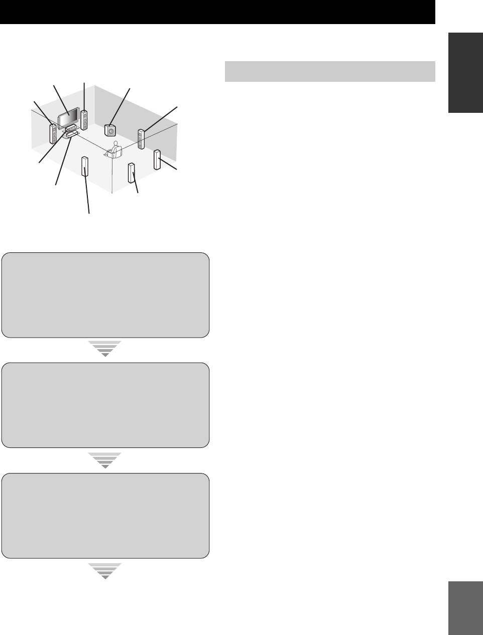
Следующие шаги описывают наиболее легкий способ просмотра кинофильмов на DVD на вашем
ВВЕДЕНИЕ
домашнем кинотеатре. Смотрите стр. 11 — 15 по подробному описанию расположения колонок.
Фронтальная
правая колонка
Подготовка: Проверьте детали
Видеоэкран
Сабвуфер
Фронтальная
Правая колонка
Подготовьте следующие детали.
левая колонка
окружающего
звучания
❏ Колонки
❏ Фронтальные колонки ……………….х 2
❏ Центральная колонка …………………x 1
❏
Колонки окружающего звучания
……х 4
Выберите колонки с магнитным экраном.
Центральная
Как минимум требуются две фронтальные
колонка
Тыловая правая
колонка
колонки. Приоритет в необходимости
окружающего
DVD-проигрыватель
звучания
других колонок следующий:
Тыловая левая
колонка окружающего
звучания
1. Две колонки окружающего звучания
Левая колонка
2. Центральная колонка
окружающего звучания
3. Одна (или две) тыловая(ые) колонка(и)
окружающего звучания
❏ Активный сабвуфер …………..…………..x 1
Выберите активный сабвуфер,
Шаг 1: Установите колонки
оборудованный входным гнездом RCA.
❏ Кабели колонок …………………..…………x 7
❏ Кабель сабвуфера …………..…………..…x 1
☞
с. 6
Выберите монофонический RCA кабель.
❏ DVD-проигрыватель ………..…………..…x 1
Выберите DVD-проигрыватель,
оборудованный коаксиальным цифровым
выходным аудиогнездом и композитным
Шаг 2: Подключите DVD-
выходным видеогнездом.
проигрыватель и
❏ Видеоэкран……….…………..…………..……x 1
Выберите телевизионный экран,
другие компоненты
видеомонитор или проектор,
☞
с. 7
оборудованный композитным входным
видеогнездом.
❏ Видеокабель …….…………..…………..……x 2
Выберите композитный видеокабель RCA.
Шаг 3: Нажмите кнопку
❏
Цифровой коаксиальный аудиокабель
…..x 1
SCENE 1
y
К данному аппарату также можно подключить два
сабвуфера. В таком случае, подготовьте два
☞
с. 8
активных сабвуфера и кабели сабвуферов.
Русский
Наслаждайтесь просмотром
DVD—диска!
5 Ru
Краткое руководство пользователя
Убедитесь в правильном подключении левого
Шаг 1: Установите колонки
канала (L), правого канала (R), “+” (красный)
и “–” (черный).
Расположите колонки в комнате и подключите их
к данному аппарату.
Фронтальные колонки и центральная
PRE OUT Гнездо SUBWOOFER 1
колонка
AUDIO MULTI CH INPUT PRE OUT DOCK VIDEO
SINGLE CENTERCENTERFRONT (8CH)
VIDEO
L
GND
R
PHONO
CD
(PLAY)
IN
CD-R
MD/
(REC)
OUT
DVD
DTV/CBL DVR VCR
OUTININ OUT
SURROUND
WOOFER
SUB
OUT
SUR. BACKSURROUND
1 2
DVDSUBWOOFERFRONTSB (8CH) ZONE 2
S VIDEO
DTV/CBL
DVR
VCR
OUTININ OUT
MONITOR
HDMI
OUT
P
R
A B
P
B
DVD
Y
COMPONENT VIDEO
P
R
P
DTV/CBL
B
Y
MD/CD-R MD/CD-R
DVD
321
4
DVDCDDTV/CBL
65
DTV/CBLDVD
ANTENNA
OUTPUT
DIGITAL
OPTICAL COAXIAL
OUT
DIGITAL INPUT
IN2IN1
FRONT B/ZONE B/
SPEAKERS
ZONE 2/PRESENCE
CENTERFRONT A
SURROUND BACK/BI-AMPSURROUND
C
DVRMONITOR OUT
AM
R
EXTRA SP
L
R
L
R
L
R
L
AC OUTLETS
GND
75Ω
FM
UNBAL.
REMOTE
TRIGGER
OUT
IN OUT
+12V
15mA MAX.
SINGLE
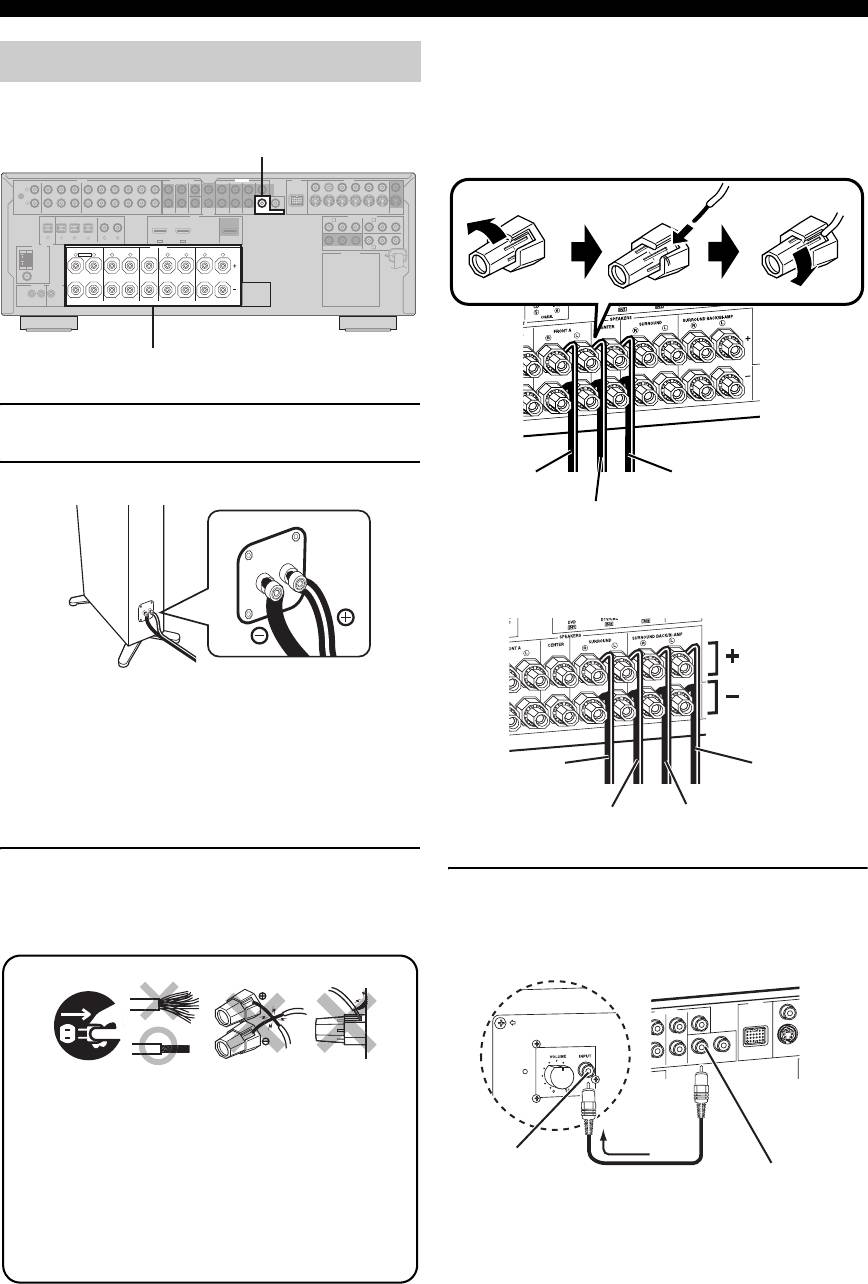
Терминалы колонок
1
Расположите колонки и сабвуфер в комнате.
2
Подключите кабели колонок к каждой колонке.
Колонки окружающего звучания и
тылового окружающего звучания
Убедитесь в правильном подключении “+” (красный) и
“–” (черный)
.
Провода отличаются цветом или формой,
например, один может быть отмечен полосками,
углублениями или складками. Подключите провод с
полосками (углублениями и т.д.) к терминалам “+”
(красный) данного аппарата и колонки. Подключите
гладкий провод к терминалам “–” (черный).
3 Подключите кабель каждой колонки к
терминалу соответствующей колонки
4 Подключите кабель сабвуфера к гнезду
данного аппарата.
SUBWOOFER PRE OUT 1 данного аппарата
и входному гнезду сабвуфера.
12 3 4
y
Также можно подключить другой сабвуфер к гнезду
SUBWOOFER PRE OUT 2.
6 Ru
Освободите Вставьте Закрепите
К фронтальной
К центральной колонке
правой колонке
К фронтальной
левой колонке
К правой колонке
К тыловой
окружающего
левой колонке
звучания
окружающего
звучания
К левой колонке
К тыловой правой колонке
окружающего звучания
окружающего звучания
4
DOCK
PRE OUT
DVD
SUR. BACK
SUBWOOFER
1
Убедитесь, что данный аппарат и сабвуфер
отсоединены от розеток переменного тока.
2
Для предотвращения короткого замыкания,
скрутите оголенные провода кабелей колонок.
3
Не давайте оголенным проводам колонок
соприкасаться друг с другом.
4
Не давайте оголенным проводам колонок соприкасаться
с любой металлической частью данного аппарата.
R
SINGLE
CENTER
S VI
ROUND
D
VID
E
Аудиовизуальный ресиверСабвуфер
12
Входное гнездо
Кабель сабвуфера
Гнездо SUBWOOFER
PRE OUT 1
Краткое руководство пользователя
y
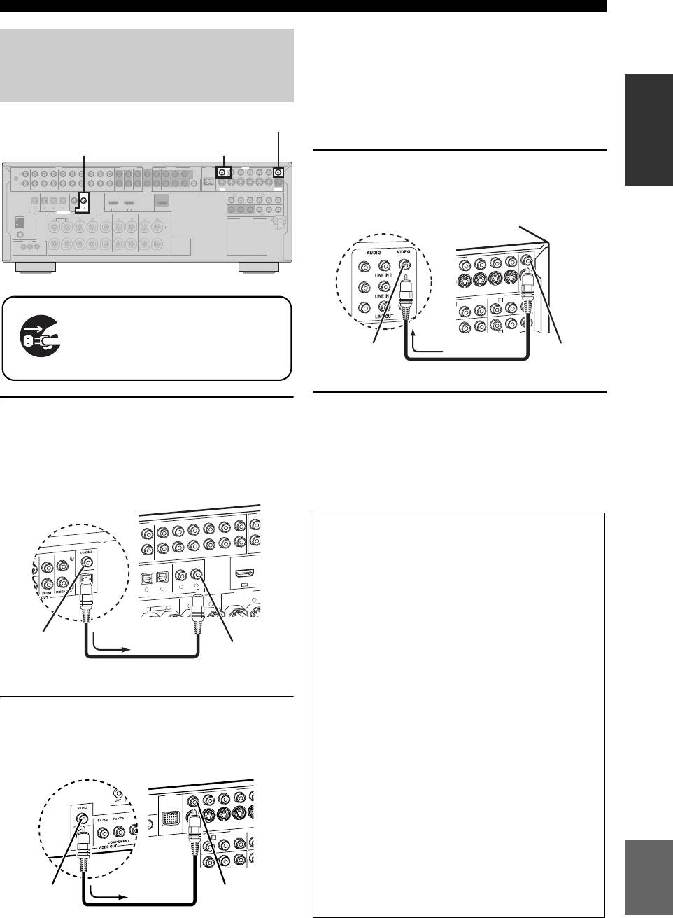
Шаг 2: Подключите DVD-
•
При подключении компонента, на котором имеется
только гнездо SCART, используйте соответствующий
проигрыватель и
преобразователь. Соединение между
преобразователем и данным аппаратом зависит от
другие компоненты
ВВЕДЕНИЕ
сигналов, доступных на преобразователе. Подробнее,
смотрите инструкцию к преобразователю.
Гнездо VIDEO MONITOR OUT
•
Данный аппарат не может передавать сигналы RGB.
Гнездо DVD DIGITAL INPUT COAXIAL Гнездо DVD VIDEO
AUDIO MULTI CH INPUT PRE OUT DOCK VIDEO
3 Подключите видеокабель к гнезду VIDEO
SINGLE CENTERCENTERFRONT (8CH)
VIDEO
L
GND
R
MONITOR OUT данного аппарата и
PHONO
CD
(PLAY)
IN
CD-R
MD/
(REC)
OUT
DVD
DTV/CBL DVR VCR
OUTININ OUT
SURROUND
WOOFER
SUB
SUR. BACKSURROUND
12
HDMI
OUT
DVDSUBWOOFERFRONTSB (8CH) ZONE 2
S VIDEO
DTV/CBL
DVR
VCR
OUTININ OUT
MONITOR
OUT
P
R
A B
P
B
DVD
COMPONENT VIDEO
Y
P
R
P
DTV/CBL
B
Y
видеовходному гнезду видеоэкрана.
MD/CD-R MD/CD-R
DVD
DIGITAL
OPTICAL COAXIAL
321
4
DVDCDDTV/CBL
65
DTV/CBLDVD
OUT
ANTENNA
OUTPUT
DIGITAL INPUT
IN2IN1
FRONT B/ZONE B/
SPEAKERS
ZONE 2/PRESENCE
CENTERFRONT A
SURROUND BACK/BI-AMPSURROUND
C
DVRMONITOR OUT
AM
R
EXTRA SP
L
R
L
R
L
R
L
AC OUTLETS
GND
FM
UNBAL.
75Ω
REMOTE
TRIGGER
OUT
IN OUT
15mA MAX.
+12V
SINGLE
Убедитесь, что данный аппарат и
DVD-проигрыватель
отсоединены от розеток
переменного тока.
4
Подключите электровилку данного аппарата и
1 Подключите цифровой коаксиальный
других компонентов к розетке переменного тока.
аудиокабель к цифровому
коаксиальному аудиовыходному гнезду
y
DVD-проигрывателя и гнезду DVD DIGITAL
Данный аппарат оборудован AC OUTLET(S) для
энергообеспечения других компонентов (за исключением модели
INPUT COAXIAL данного аппрата.
для Кореи). Смотрите стр. 28 для подробной информации.
AUDIO
AUDIO
DVD
2
Подключите видеокабель к композитному
видеовыходному гнезду DVD-проигрывателя
и гнезду DVD VIDEO данного аппарата.
Русский
7 Ru
M
SB (8C
SPEAKERS
DIGITAL INPUT
H
FRONT (8C
H
DVD
CD
DVD
DVD
DTV/CBL
COAXIAL
OPTICAL
S
U
D/
DVD
FRONT A
CENTER
FRONT B/ZONE B/
ZONE 2/PRESENCE
D
Аудиовизуальный ресивер
DVD-проигрыватель
O
U
T
IN
DVR
VCR
O
U
T
IN
OUT
-R
(REC)
DTV/CBL
4
5
6
IN1
3
R
L
R
L
R
EXTRA SP
Цифровое
коаксиальное
Гнездо DVD
аудиовыходн
DIGITAL INPUT
ое гнездо
Цифровой коаксиальный
COAXIAL
аудиокабель
VIDEO
DOCK
COMPONENT
V
V
I
DEO
S VIDEO
DVR
DVD
DTV/CBL
DVD
OUT
VID
EO
DVR
COMPONENT VIDEO
DTV/CBL
DVD
■ Дополнительные подключения
• Использование других типов комбинаций
колонок ☞ с. 11
• Подключение видеоэкрана с помощью
различных методов подключения ☞ с. 20
•
Подключение DVD-проигрывателя с помощью
различных методов подключения
☞ с. 21
• Подключение DVD-магнитофона или
цифрового видеомагнитофона ☞ с. 22
• Подключение телеприставки ☞ с. 22
• Подключение CD-плеера, MD-
магнитофона, или проигрывателя ☞ с. 23
• Подключение внешнего усилителя ☞ с. 24
• Подключение DVD-проигрывателя с
DVD-проигрыватель
Аудиовизуальный ресивер
помощью аналогового многоканального
аудиоподключения ☞ с. 25
• Подключение универсального дока Yamaha
для iPod или адаптера Bluetooth ☞ с. 25
IN
OUT
A
P
B
Y
P
R
P
R
• Использование гнезд REMOTE IN/OUT
☞ с. 26
• Использование гнезд VIDEO AUX на
фронтальной панели ☞ с. 26
Композитное
Гнездо DVD
видеовыходно
VIDEO
• Подключение ЧМ/АМ антенны ☞ с. 27
е гнездо
Видеокабель
DVR
IN
VCR
OUT
MONITOR
IN
OUT
OUT
P
R
P
B
Y
P
B
Y
B
C
Аудиовизуальный ресивер
Видеоэкран
Видеовходное
Гнездо VIDEO
гнездо
MONITOR OUT
Видеокабель
Краткое руководство пользователя
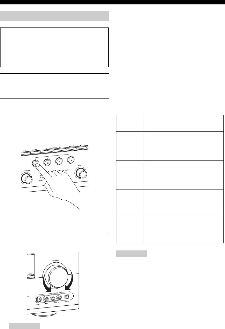
■ О функции SCENE
Шаг 3: Нажмите кнопку SCENE 1
Нажатием только одной кнопки SCENE можно
включить данный аппарат и вызвать любимый
источник приема и программу звукового поля в
Проверьте тип подключенных колонок.
соответствии с шаблоном SCENE, назначенным
При использовании колонок на 6 Ом, установите
для кнопки SCENE. Шаблоны SCENE — это
“SP IMP.” на “6
Ω
MIN” до использования данного
встроенные комбинации источников приема и
аппарата (смотрите стр. 28). Колонки на 4 Ом
программ звукового поля.
также могут использоваться в качестве
фронтальных колонок (смотрите стр. 106).
y
При подключении изделия Yamaha с функцией сигналов
управления SCENE, данный аппарат может
автоматически включать компонент и запускать
1 Включите видеоэкран и затем установите
воспроизведение. Для более подробной информации,
селектор источника приема видеоэкрана
смотрите инструкцию по эксплуатации к DVD-
на данный аппарат.
проигрывателю.
■ Назначенные по умолчанию шаблоны
2 Нажмите кнопку
S
SCENE1.
SCENE
Данный аппарат включается. На дисплее
фронтальной панели отображается “DVD
Movie Viewing”, и данный аппарат
Кнопка
Название шаблона SCENE и его
SCENE по
описание
автоматически оптимизирует свой статус для
умолчанию
воспроизведения DVD.
SCENE
DVD Movie Viewing
1
– источник приема: DVD
– программа звукового поля: Sci-Fi
Просмотр кинофильма от
подключенного DVD-проигрывателя.
SCENE
Music Disc Listening
2
– источник приема: DVD
–
программа звукового поля: 2ch Stereo
Прослушивание музыкального диска от
подключенного DVD-проигрывателя.
SCENE
TV Viewing
*1
3
– источник приема: DTV/CBL
–
программа звукового поля: Straight
Просмотр телевизионной программы.
y
SCENE
Radio Listening
*2, *3, *4
Когда данный аппарат находится в режиме SCENE,
4
– источник приема: TUNER
высвечивается индикатор выбранной кнопки SCENE.
–
программа звукового поля: 7ch Enhancer
Прослушивание музыкальной
3 Поворачивайте
J
VOLUME для
программы от ЧМ радиостанции.
регулировки громкости.
Примечания
*1
Требуется заранее подключить к данному аппарату
тюнер кабельного телевидения или спутниковый тюнер.
Смотрите стр. 22 для более подробной информации.
*2
Требуется заранее подключить к данному аппарату
поставляемые ЧМ и АМ антенны. Смотрите стр. 27
для более подробной информации.
*3
Требуется заранее настроиться на нужную радиостанцию.
Смотрите стр. 53 до 56 для информации по настройке.
*4
Для достижения наилушего приема, изменяйте направление
подключенной рамочной АМ антенны, или отрегулируйте
расположение конца внутренней ЧМ антенны.
y
Примечание
Можно переключать назначенный шаблон SCENE для
кнопок SCENE. Смотрите стр. 37 для более подробной
При переключении источника приема или программы
информации.
звукового поля, режим SCENE отключается.
8 Ru
Краткое руководство пользователя
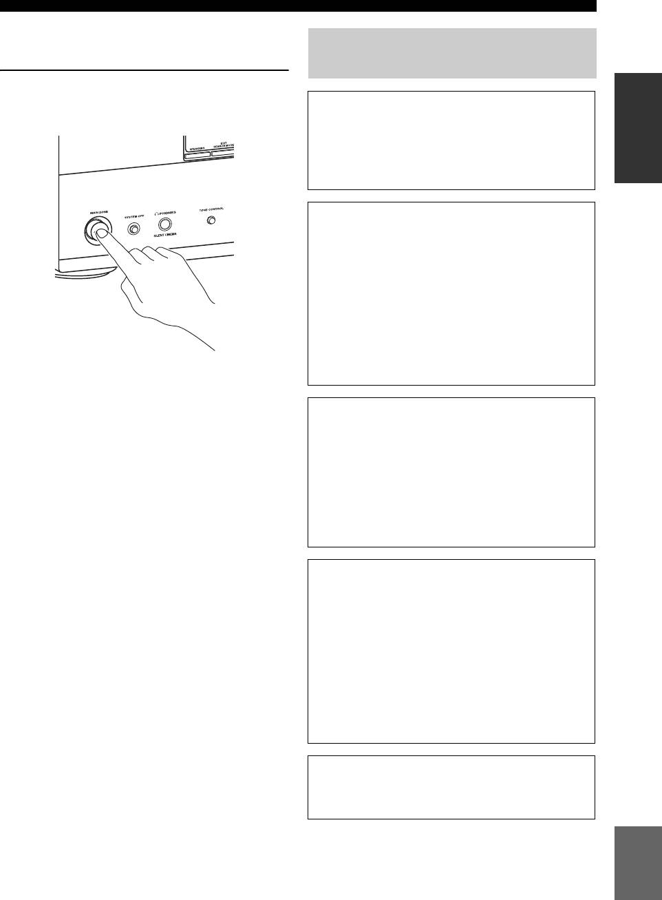
■ После использования данного
аппарата...
Для чего вам нужен данный
аппарат?
Нажмите
K
MAIN ZONE ON/OFF для
ВВЕДЕНИЕ
установки данного аппарата в режим
■ Настройка шаблонов SCENE
ожидания.
• Использование различных шаблонов
SCENE ☞ с. 37
• Создание своих оригинальных шаблонов
SCENE ☞ с. 40
■ Использование различных
источников приема
• Основное управление данным аппаратом
☞ с. 42
• Прослушивание ЧМ/АМ радиопрограмм
☞ с. 53
• Использование iPod с данным аппаратом
☞ с. 60
• Использование компонентов Bluetooth
Данный аппарат устанавливается на режим
☞ с. 62
ожидания и потребляет малое количество
электроэнергии для приема инфракрасных
сигналов от пульта ДУ. Для включения данного
■ Использование различных
аппарата от режима ожидания, нажмите нужные
звуковых функций
кнопки
S
SCENE (или
4
SCENE) или
K
MAIN
E
• Использование различных программ
ZONE ON/OFF (или
POWER). Более подробно,
звукового поля ☞ с. 48
Смотрите стр. 29.
• Использование режима чистого прямого
звучания для получения высокоточного
звучания ☞ с. 52
• Настройка программ звукового поля ☞ с. 64
■ Настройка параметров данного
аппарата
• Автоматическая оптимизация параметров
колонок для комнаты для прослушивания
(AUTO SETUP) ☞ с. 32
• Ручная настройка различных параметров
данного аппарата ☞ с. 71
• Настройка пульта ДУ ☞ с. 91
• Регулировка дополнительных параметров
☞ с. 106
■ Дополнительная функция
• Автоматическое отключение данного
аппарата ☞ с. 47
Русский
9 Ru
| Название | Русский | English |
|---|---|---|
| RX-V663 OWNER’S MANUAL | — |
[5.3MB] |
| RX-V663 Owner’s Manual | — |
[2.6MB] |
| RX-V663 ИНСТРУКЦИЯ ПО ЭКСПЛУАТАЦИИ |
[5.3MB] |
[5.3MB] |
Инструкция и руководство для
Yamaha RX-V663  на русском на английском


250 страниц подробных инструкций и пользовательских руководств по эксплуатации
 07:27
07:27
Ремонт Yamaha RX-V661 не включается или выключается через короткое время
 08:16
08:16
Yamaha RX-V663; Dump Finds!
 06:59
06:59
2008 Yamaha RX-V663 Receiver in Action
 01:55
01:55
amplificador yamaha rx v663
 21:06
21:06
teleton a660 (mitsubishi) и yamaha rx-v663 на TQWP Ноэма 100гдш65
 06:05
06:05
2008 Yamaha RX-V663 receiver review second part
 10:03
10:03
yamaha rx-v663 sound
 05:41
05:41
Yamaha RX-V663BL 7.1-Channel Digital Home Theater Receiver
YAMAHA ELECTRONICS CORPORATION, USA 6660 ORANGETHORPE AVE., BUENA PARK, CALIF. 90620, U.S.A.
YAMAHA CANADA MUSIC LTD. 135 MILNER AVE., SCARBOROUGH, ONTARIO M1S 3R1, CANADA
YAMAHA ELECTRONIK EUROPA G.m.b.H. SIEMENSSTR. 22-34, 25462 RELLINGEN BEI HAMBURG, GERMANY
YAMAHA ELECTRONIQUE FRANCE S.A. RUE AMBROISE CROIZAT BP70 CROISSY-BEAUBOURG 77312 MARNE-LA-VALLEE CEDEX02, FRANCE
YAMAHA ELECTRONICS (UK) LTD. YAMAHA HOUSE, 200 RICKMANSWORTH ROAD WATFORD, HERTS WD18 7GQ, ENGLAND
YAMAHA SCANDINAVIA A.B. J A WETTERGRENS GATA 1, BOX 30053, 400 43 VÄSTRA FRÖLUNDA, SWEDEN
YAMAHA MUSIC AUSTRALIA PTY. LTD. LEVEL 1, 99 QUEENSBRIDGE STREET, SOUTHBANK, VIC 3006, AUSTRALIA
© 2008 All rights reserved.
RX-V663
Printed in Malaysia
WN24980
RX-V663
AV Receiver
OWNER’S MANUAL
ИНСТРУКЦИЯ ПО ЭКСПЛУАТАЦИИ
F
HUGHES NETWORK SYSTEMS
0069
HYPSON
0099
ITT
0068, 0131, 0267
ITV
0064, 0305
IMPERIAL
0027
INTERFUNK
0108
JVC
0068, 0072, 0094
JENSEN
0068
KEC
0064, 0305
KLH
0099
KAISUI
0099
KENWOOD
0068, 0094
KODAK
0062, 0064
KOLIN
0068, 0070
KORPEL
0099
LG
0064, 0069, 0072,
0507
LXI
0064
LENCO
0305
LEYCO
0099
LLOYD’S
0027
LOEWE
0064, 0108, 1589
LOGIK
0099, 0267
LUXOR
0070, 0075, 0131
M ELECTRONIC
0027
MEI
0062
MGA
0070, 0267
MGN TECHNOLOGY
0267
MTC
0027, 0267
MAGNASONIC
1305
MAGNAVOX 0027, 0062, 0066,
0108, 1808
MAGNIN
0267
MANESTH
0072, 0099
MARANTZ
0062, 0108
MARTA
0064
MATSUI
0375, 0379
MATSUSHITA
0062
MEDION
0375
MEMOREX
0027, 0062, 0064,
0066, 0074, 0075,
0131, 0267, 0334,
0375, 1264
MEMPHIS
0099
METZ
0064, 0374, 1589
MINOLTA
0069
MITSUBISHI
0068, 0070, 0094,
0108, 0834
MOTOROLA
0062, 0075
MULTITECH
0027, 0099
MURPHY
0027
MYRYAD
0108
NAD
0131
NEC
0062, 0064, 0068,
0075, 0094, 0131
NATIONAL
0253
NECKERMANN
0108
NESCO
0099
NEWAVE
0064
NIKKO
0064
NOBLEX
0267
NOKIA
0068, 0131, 0267
NORDMENDE
0068, 0347
OCEANIC
0027, 0068
OKANO
0342, 0375
OLYMPUS
0062, 0253
OPTIMUS
0064, 0075, 0131,
0459
ORION
0211, 0375, 0379,
1506
OSAKI
0027, 0064, 0099
OTTO VERSAND
0108
PALLADIUM 0064, 0068, 0099
PANASONIC
0062, 0252, 0253,
0643, 1062, 1589
PATHE MARCONI
0068
PENNEY
0062, 0064, 0069,
0267, 1062, 1264
PENTAX
0069
PERDIO
0027
PHILCO
0062
PHILIPS
0062, 0108, 0645,
1108, 1208
PHONOLA
0108
PILOT
0064
PIONEER
0069, 0094, 0108
POLK AUDIO 0108
PROFITRONIC
0267
PROLINE
0027
PROSCAN
0087, 1087
PROTEC
0099
PULSAR
0066
PYE
0108
QUASAR
0062, 1062
QUELLE
0108
RCA
0062, 0069, 0087,
0267, 0834, 1062,
1087
RADIOSHACK
0027
RADIOLA
0108
RADIX
0064
RANDEX
0064
REALISTIC
0027, 0062, 0064,
0074, 0075, 0131
REOC
0375
REPLAYTV
0641, 0643
REX
0068
ROADSTAR
0064, 0099, 0267,
0305
RUNCO
0066
SBR
0108
SEG
0267
SEI
0108
STS
0069
SABA
0068, 0347
SALORA
0070
SAMPO
0064, 0075
SAMSUNG
0072, 0267, 0459
SANKY
0066, 0075
SANSUI
0027, 0068, 0094,
1506
SANYO
0074, 0131, 0267
SAVILLE
0379
SCHAUB LORENZ
0027, 0068,
0131
SCHNEIDER
0027, 0099, 0108
SCOTT
0070, 0072, 0211
SEARS
0027, 0062, 0064,
0069, 0074, 0131,
1264
SELECO
0068
SEMP
0072
SHARP
0075, 0834
SHINTOM
0099, 0131
SIEMENS
0064, 0108, 0131
SILVA
0064
SINGER
0072, 0099
SINUDYNE
0108
SONIC BLUE 0641, 0643
SONTEC
0064
SONY
0027, 0059, 0060,
0062, 0663, 1259
SUNKAI
0375
SUNSTAR
0027
SUNTRONIC
0027
SYLVANIA
0027, 0062, 0108,
0070, 1808
SYMPHONIC 0027
TMK
0267
TANDY
0027, 0131
TASHIKO
0027, 0064
TATUNG
0027, 0068, 0072,
0094, 0108
TEAC
0027, 0068, 0305,
0334, 0669
TECHNICS
0062, 0253
TECO
0062, 0064, 0068,
0075
TEKNIKA
0027, 0062, 0064
TELEAVIA
0068
TELEFUNKEN
0068, 0347
TENOSAL
0099
TENSAI
0027
THOMAS
0027
THOMSON
0068, 0087, 0094,
0347
THORN
0068, 0131
TIVO
0645, 0663
TOSHIBA
0068, 0070, 0072,
0094, 0108, 0872
TOTEVISION 0064, 0267
UHER
0267
UNITECH
0267
UNIVERSUM 0027, 0064, 0108,
0267
VECTOR
0072
VICTOR
0068, 0094
VIDEO CONCEPTS 0072
VIDEOMAGIC
0064
VIDEOSONIC 0267
VILLAIN
0027
WARDS
0027, 0062, 0069,
0074, 0075, 0087,
0099, 0108, 0267
WHITE WESTINGHOUSE
0099
XR-1000
0027, 0062, 0099
YAMAHA
0068
YAMISHI
0099
YOKAN
0099
YOKO
0267
ZENITH
0027, 0060, 0066,
1506
RX-V663_F-cv.fm Page 1 Tuesday, January 29, 2008 9:47 AM
Black process 45.0° 240.0 LPI

English, Caution: read this before operating your unit, For u.k. customers
Special instructions for u.k. model
- Изображение
- Текст
CAUTION: READ THIS BEFORE OPERATING YOUR UNIT.
En
1
To assure the finest performance, please read this manual
carefully. Keep it in a safe place for future reference.
2
Install this sound system in a well ventilated, cool, dry, clean
place – away from direct sunlight, heat sources, vibration,
dust, moisture, and/or cold. Allow ventilation space of at least
30 cm on the top, 20 cm on the left and right, and 20 cm on
the back of this unit.
3
Locate this unit away from other electrical appliances, motors,
or transformers to avoid humming sounds.
4
Do not expose this unit to sudden temperature changes from
cold to hot, and do not locate this unit in an environment with
high humidity (i.e. a room with a humidifier) to prevent
condensation inside this unit, which may cause an electrical
shock, fire, damage to this unit, and/or personal injury.
5
Avoid installing this unit where foreign objects may fall onto
this unit and/or this unit may be exposed to liquid dripping or
splashing. On the top of this unit, do not place:
–
other components, as they may cause damage and/or
discoloration on the surface of this unit.
–
burning objects (i.e. candles), as they may cause fire,
damage to this unit, and/or personal injury.
–
containers with liquid in them, as they may fall and liquid
may cause electrical shock to the user and/or damage to
this unit.
6
Do not cover this unit with a newspaper, tablecloth, curtain,
etc. in order not to obstruct heat radiation. If the temperature
inside this unit rises, it may cause fire, damage to this unit,
and/or personal injury.
7
Do not plug in this unit to a wall outlet until all connections
are complete.
8
Do not operate this unit upside-down. It may overheat,
possibly causing damage.
9
Do not use force on switches, knobs and/or cords.
10 When disconnecting the power cable from the wall outlet,
grasp the plug; do not pull the cable.
11 Do not clean this unit with chemical solvents; this might
damage the finish. Use a clean, dry cloth.
12 Only voltage specified on this unit must be used. Using this
unit with a higher voltage than specified is dangerous and may
cause fire, damage to this unit, and/or personal injury. Yamaha
will not be held responsible for any damage resulting from use
of this unit with a voltage other than specified.
13 To prevent damage by lightning, keep the power cord and
outdoor antennas disconnected from a wall outlet or the unit
during a lightning storm.
14 Do not attempt to modify or fix this unit. Contact qualified
Yamaha service personnel when any service is needed. The
cabinet should never be opened for any reasons.
15 When not planning to use this unit for long periods of time
(i.e. vacation), disconnect the AC power plug from the wall
outlet.
16 Install this unit near the AC outlet and where the AC power
plug can be reached easily.
17 Be sure to read the “Troubleshooting” section on common
operating errors before concluding that this unit is faulty.
18 Before moving this unit, press LSYSTEM OFF to set this
unit to the standby mode, and then disconnect the AC power
plug from the AC wall outlet.
19 VOLTAGE SELECTOR (Asia and General models only)
The VOLTAGE SELECTOR on the rear panel of this unit
must be set for your local main voltage BEFORE plugging
into the AC wall outlet. Voltages are:
Asia model ………………………. 220/230–240 V AC, 50/60 Hz
General model …….. 110/120/220/230–240 V AC, 50/60 Hz
20 The batteries shall not be exposed to excessive heat such as
sunshine, fire or like.
21 Excessive sound pressure from earphones and headphones can
cause hearing loss.
■ For U.K. customers
If the socket outlets in the home are not suitable for the plug
supplied with this appliance, it should be cut off and an
appropriate 3 pin plug fitted. For details, refer to the
instructions described below.
The plug severed from the mains lead must be destroyed, as a
plug with bared flexible cord is hazardous if engaged in a live
socket outlet.
■ Special Instructions for U.K. Model
Caution: Read this before operating your unit.
WARNING
TO REDUCE THE RISK OF FIRE OR ELECTRIC
SHOCK, DO NOT EXPOSE THIS UNIT TO RAIN OR
MOISTURE.
As long as this unit is connected to the AC wall outlet, it is
not disconnected from the AC power source even if you
turn off this unit by L SYSTEM OFF. In this state, this
unit is designed to consume a very small quantity of
power.
Note
IMPORTANT
THE WIRES IN MAINS LEAD ARE COLOURED IN
ACCORDANCE WITH THE FOLLOWING CODE:
Blue: NEUTRAL
Brown: LIVE
As the colours of the wires in the mains lead of this apparatus
may not correspond with the coloured markings identifying
the terminals in your plug, proceed as follows:
The wire which is coloured BLUE must be connected to the
terminal which is marked with the letter N or coloured
BLACK. The wire which is coloured BROWN must be
connected to the terminal which is marked with the letter L or
coloured RED.
Making sure that neither core is connected to the earth
terminal of the three pin plug.
This symbol mark is according to the EU
directive 2002/96/EC.
This symbol mark means that electrical
and electronic equipment, at their end-of-
life, should be disposed of separately from
your household waste.
Please act according to your local rules
and do not dispose of your old products
with your normal household waste.

En PREP ARA TION IN TRODUC TI ON BA S IC OPERA T ION AD …
Страница 3
- Изображение
- Текст

FEATURES
2
En
Built-in 7-channel power amplifier
◆ Minimum RMS output power
(20 Hz to 20 kHz, 0.06% THD, 8
Ω)
Front: 95 W + 95 W
Center: 95 W
Surround: 95 W + 95 W
Surround back: 95 W + 95 W
SCENE function
◆ Preset SCENE templates for various situations
◆ SCENE templates for customizing capability
◆ Controlling Yamaha SCENE control signal support
component (some models only) working with the SCENE
function
Sound field programs
◆ Proprietary Yamaha technology for the creation of sound
fields
◆ Compressed Music Enhancer mode
◆ Virtual CINEMA DSP
◆ SILENT CINEMA
Digital audio decoders
◆ Dolby TrueHD, Dolby Digital Plus decoder
◆ DTS-HD Master Audio, DTS-HD High Resolution Audio
decoder
◆ Dolby Digital/Dolby Digital EX decoder
◆ DTS/DTS-ES Matrix 6.1, Discrete 6.1, DTS 96/24 decoder
◆ Dolby Pro Logic/Dolby Pro Logic II/Dolby Pro Logic IIx
decoder
Radio tuners
◆ FM/AM tuning capability
◆ Radio Data System capability (Europe and Russia models
only)
HDMI™ (High-Definition Multimedia Interface)
◆ HDMI interface for standard, enhanced or
high-definition video as well as multi-channel digital audio
based on HDMI version 1.3a (HDMI is licensed by HDMI
Licensing LLC.)
– Automatic audio and video synchronization (lip sync)
information capability
– Deep Color video signal (30/36 bit) transmission capability
– “x.v.Color” video signal transmission capability
– High refresh rate and high resolution video signals
capability
– High definition digital audio format signals capability
◆ HDCP (High-bandwidth Digital Content Protection System)
licensed by Digital Content Protection, LLC.
◆ Analog video to HDMI digital video up-conversion
(composite video
↔ S-video ↔ component video → HDMI
digital video) capability for monitor out
DOCK terminal
◆ DOCK terminal to connect a Yamaha iPod universal dock
(such as YDS-10, sold separately) or Bluetooth adapter (such
as YBA-10, sold separately)
Other features
◆ YPAO (Yamaha Parametric Room Acoustic Optimizer) for
automatic speaker setup
◆ 192-kHz/24-bit D/A converter
◆ OSD (on-screen display) menus that allow you to optimize
this unit to suit your individual audiovisual system
◆ 5.1 or 7.1-channel additional input jacks for discrete multi-
channel input
◆ Component video input/output capability includes
(3 COMPONENT VIDEO INs and 1 MONITOR OUT)
◆ Digital video signal conversion (composite video ↔ S-video
↔ component video) capability for monitor out
◆ Pure Direct mode for pure hi-fi sound for all sources
◆ Adaptive dynamic range controlling capability
◆ Adaptive DSP effect level controlling capability
◆ iPod controlling capability
◆ Remote control with preset remote control codes, learning,
and macro capability
◆ Zone 2 custom installation facility
◆ Bi-amplification connection capability
◆ Sleep timer
Check that you received all of the following parts.
❏ Remote control
❏ Batteries (4) (AAA, R03, UM-4)
❏ Optimizer microphone
❏ AM loop antenna
❏ Indoor FM antenna
Features
Supplied accessories

Notice
3
En
IN
TR
ODUC
TI
ON
English
Manufactured under license from Dolby Laboratories.
“Dolby”, “Pro Logic”, and the double-D symbol are trademarks
of Dolby Laboratories.
Manufactured under license under U.S. Patent No’s:
5,451,942;5,956,674;5,974,380;5,978,762;6,226,616;6,487,535
& other U.S. and worldwide patents issued & pending. DTS is a
registered trademark and the DTS logos, Symbol, DTS-HD and
DTS-HD Master Audio are trademark of DTS, Inc. © 1996-2007
DTS, Inc. All Rights Reserved.
iPod™
“iPod” is a trademark of Apple Inc., registered in the U.S. and
other countries.
Bluetooth™
Bluetooth is a registered trademark of the Bluetooth SIG and is
used by Yamaha in accordance with a license agreement.
“HDMI”, the “HDMI” logo and “High-Definition Multimedia
Interface” are trademarks or registered trademarks of HDMI
Licensing LLC.
x.v.Color™
“x.v.Color” is a trademark of Sony Corporation.
“SILENT CINEMA” is a trademark of Yamaha Corporation.
Notice
About this manual
• y indicates a tip for your operation.
• Some operations can be performed by using either the
buttons on the front panel or the ones on the remote
control. In case the button names differ between the front
panel and the remote control, the button name on the
remote control is given in parentheses.
• This manual is printed prior to production. Design and
specifications are subject to change in part as a result of
improvements, etc. In case of differences between the
manual and product, the product has priority.
• “ASPEAKERS” or “5DVD” (example) indicates the
name of the parts on the front panel or the remote control.
Refer to the attached sheet or the pages at the end of this
manual for the information about each position of the
parts.
•
The symbol “
☞” with page number(s) indicates the
corresponding reference page(s).

GETTING STARTED
4
En
■ Installing batteries in the remote control
1
Press the
part and slide the battery
compartment cover off.
2
Insert the four supplied batteries
(AAA, R03, UM-4) according to the polarity
markings (+ and –) on the inside of the
battery compartment.
3
Slide the cover back until it snaps into place.
• Change all of the batteries if you notice the following
conditions:
– the operation range of the remote control decreases.
– the transmit indicator (2) does not flash or its light becomes
dim.
• Do not use an old battery together with a new one.
• Do not use different types of batteries (such as alkaline and
manganese batteries) together. Read the packaging carefully as
these different types of batteries may have the same shape and
color.
• If the batteries have leaked, dispose of them immediately. Avoid
touching the leaked material or letting it come into contact with
clothing, etc. Clean the battery compartment thoroughly before
installing new batteries.
• Do not throw away batteries with general house waste; dispose
of them correctly in accordance with your local regulations.
• If the remote control is without batteries for more than 2
minutes, or if exhausted batteries remain in the remote control,
the contents of the memory may be cleared. When the memory
is cleared, insert new batteries, set up the remote control code
and program any acquired functions that may have been
cleared.
■ VOLTAGE SELECTOR
(Asia and General models only)
Getting started
Notes
1
3
2
Caution
The VOLTAGE SELECTOR on the rear panel of this
unit must be set for your local voltage BEFORE
plugging the power cable into the AC wall outlet.
Improper setting of the VOLTAGE SELECTOR may
cause damage to this unit and create a potential fire
hazard.
Rotate the VOLTAGE SELECTOR clockwise or
counterclockwise to the correct position using a
straight slot screwdriver.
Voltages are as follows:
Asia model ………………. 220/230–240 V AC, 50/60 Hz
General model
………………… 110/120/220/230–240 V AC, 50/60 Hz
230-
240V
VOLTAGE
SELECTOR
Voltage indication

Quick start guide, Preparation: check the items, Enjoy dvd playback! step 1: set up your speakers
P. 6, P. 7, P. 8
- Изображение
- Текст
Quick start guide
5
En
IN
TR
ODUC
TI
ON
English
The following steps describe the easiest way to enjoy DVD movie playback in your home theater. See pages 11 to 15 for
details of the speaker placement.
Prepare the following items.
❏ Speakers
❏ Front speakers …………………………….. x 2
❏ Center speaker ……………………………. x 1
❏ Surround speakers ………………………. x 4
Select magnetically shielded speakers. The
minimum required speakers are two front speakers.
The priority of the requirement of other speakers is
as follows:
1. Two surround speakers
2. Center speaker
3. One (or two) surround back speaker(s)
❏ Active subwoofer …………………………….. x 1
Select an active subwoofer equipped with an RCA
input jack.
❏ Speaker cables ………………………………… x 7
❏ Subwoofer cable ……………………………… x 1
Select a monaural RCA cable.
❏ DVD player ………………………………………. x 1
Select DVD player equipped with coaxial digital
audio output jack and composite video output
jack.
❏ Video monitor ………………………………….. x 1
Select a TV monitor, video monitor or projector
equipped with a composite video input jack.
❏ Video cable ……………………………………… x 2
Select an RCA composite video cable.
❏ Digital coaxial audio cable ……………….. x 1
y
You can also connect two subwoofers to this unit. In this
case, prepare two active subwoofers and subwoofer cables.
Quick start guide
Front right
speaker
Subwoofer
Surround back
right speaker
Surround left
speaker
Front left
speaker
Surround back left
speaker
Surround right
speaker
Center
speaker
Video monitor
DVD player
Enjoy DVD playback!
Step 1: Set up your speakers
☞
P. 6
Step 2: Connect your DVD player
and other components
Step 3: Press SCENE 1 button
☞
P. 7
☞
P. 8
Preparation: Check the items

Step 1: set up your speakers, P. 6, Place your speakers and subwoofer in the room
Connect speaker cables to each speaker, Quick start guide, Speaker terminals pre out subwoofer 1 jack
- Изображение
- Текст
Quick start guide
6
En
Place your speakers in the room and connect them to this
unit.
1
Place your speakers and subwoofer in the
room.
2
Connect speaker cables to each speaker.
Be sure to connect the “+” (red) and “–” (black) properly
.
Cables are colored or shaped differently, perhaps with a
stripe, groove or ridge. Connect the striped (grooved, etc.)
cable to the “+” (red) terminals of this unit and your speaker.
Connect the plain cable to the “–” (black) terminals.
3
Connect each speaker cable to the
corresponding speaker terminal of this unit.
Be sure to connect the left channel (L), right channel
(R), “+” (red) and “–” (black) properly.
Front speakers and center speaker
Surround and surround back speakers
4
Connect the subwoofer cable to the
SUBWOOFER PRE OUT 1 jack of this unit
and the input jack of the subwoofer.
y
You can also connect another subwoofer to the SUBWOOFER
PRE OUT 2 jack.
Step 1: Set up your speakers
AC OUTLETS
R
L
AUDIO
MULTI CH INPUT
PRE OUT
DOCK
VIDEO
COMPONENT VIDEO
HDMI
DIGITAL INPUT
ANTENNA
REMOTE
DIGITAL
OUTPUT
TRIGGER
OUT
SPEAKERS
DVD
SUBWOOFER
FRONT
SB (8CH)
ZONE 2
OUT
SUB
WOOFER
SUR. BACK
SURROUND
SINGLE
CENTER
CENTER
FRONT (8CH)
SURROUND
DVD
DTV/CBL
S VIDEO
VIDEO
DTV/CBL
DVR
DVR
MONITOR OUT
VCR
OUT
IN
IN
OUT
1
2
DVD
DVD
CD
DTV/CBL
OPTICAL
COAXIAL
DVD
OUT
SURROUND BACK/BI-AMP
SURROUND
SINGLE
CENTER
FRONT A
AM
+12V
15mA MAX.
GND
FRONT B/ZONE B/
ZONE 2/PRESENCE
DTV/CBL
DVD
MD/CD-R MD/CD-R
PHONO
GND
CD
MD/
CD-R
IN
(PLAY)
OUT
(REC)
DTV/CBL
DVR
VCR
OUT
IN
IN
OUT
IN
OUT
MONITOR
OUT
FM
UNBAL.
R
L
R
L
R
L
R
L
6
5
4
3
2
1
IN2
IN1
EXTRA SP
Y
P
R
P
B
Y
P
R
P
B
A
B
C
75
Ω
Speaker terminals
PRE OUT SUBWOOFER 1 jack
1
2
3
4
4
1 Make sure that this unit and the subwoofer are
unplugged from the AC wall outlets.
2 Twist the exposed wires of the speaker cables
together to prevent short circuits.
3 Do not let the bare speaker wires touch each
other.
4 Do not let the bare speaker wires touch any
metal part of this unit.
To the front left
speaker
To the front right
speaker
To the center speaker
Loosen
Insert
Tighten
To the surround
right speaker
To the surround
back left speaker
To the surround
left speaker
To the surround
back right speaker
PRE OUT
DOCK
DVD
SUBWOOFER
SUR. BACK
RROUND
SINGLE
CENTER
S VID
VIDE
1
2
SUBWOOFER PRE
OUT 1 jack
Subwoofer cable
Input jack
AV receiver
Subwoofer

Step 2: connect your dvd player, And other components, P. 7
For further connections, Quick start guide
- Изображение
- Текст
Quick start guide
7
En
IN
TR
ODUC
TI
ON
English
1
Connect the digital coaxial audio cable to the
digital coaxial audio output jack of your DVD
player and the DVD DIGITAL INPUT COAXIAL
jack of this unit.
2
Connect the video cable to the composite
video output jack of your DVD player and
DVD VIDEO jack of this unit.
y
• When you connect a component that has only a SCART
jack, use an appropriate converter. The connection
between a converter and this unit depends on signals that
are available on the converter. For details, refer to the
instructions of your converter.
• This unit cannot transmit RGB signals.
3
Connect the video cable to the VIDEO
MONITOR OUT jack of this unit and the video
input jack of your video monitor.
4
Connect the power plug of this unit and other
components into the AC wall outlet.
y
This unit is equipped with AC OUTLET(S) for the power
supply of the other components (except Korea model). See
page 28 for details.
Step 2: Connect your DVD player
and other components
AC OUTLETS
R
L
AUDIO
MULTI CH INPUT
PRE OUT
DOCK
VIDEO
COMPONENT VIDEO
HDMI
DIGITAL INPUT
ANTENNA
REMOTE
DIGITAL
OUTPUT
TRIGGER
OUT
SPEAKERS
DVD
SUBWOOFER
FRONT
SB (8CH)
ZONE 2
OUT
SUB
WOOFER
SUR. BACK
SURROUND
SINGLE
CENTER
CENTER
FRONT (8CH)
SURROUND
DVD
DTV/CBL
S VIDEO
VIDEO
DTV/CBL
DVR
DVR
MONITOR OUT
VCR
OUT
IN
IN
OUT
1
2
DVD
DVD
CD
DTV/CBL
OPTICAL
COAXIAL
DVD
OUT
SURROUND BACK/BI-AMP
SURROUND
SINGLE
CENTER
FRONT A
AM
+12V
15mA MAX.
GND
FRONT B/ZONE B/
ZONE 2/PRESENCE
DTV/CBL
DVD
MD/CD-R MD/CD-R
PHONO
GND
CD
MD/
CD-R
IN
(PLAY)
OUT
(REC)
DTV/CBL
DVR
VCR
OUT
IN
IN
OUT
IN
OUT
MONITOR
OUT
FM
UNBAL.
R
L
R
L
R
L
R
L
6
5
4
3
2
1
IN2
IN1
EXTRA SP
Y
P
R
P
B
Y
P
R
P
B
A
B
C
75
Ω
Make sure that this unit and the DVD
player are unplugged from the AC
wall outlets.
DVD DIGITAL INPUT COAXIAL jack
DVD VIDEO jack
VIDEO MONITOR OUT jack
DVD
AUDIO
AUDIO
M
DIGITAL INPUT
SPEAKERS
SB (8CH
FRONT (8CH
DVD
DVD
CD
DTV/CBL
DVD
OPTICAL
COAXIAL
SU
CENTER
FRONT A
FRONT B/ZONE B/
ZONE 2/PRESE
NCE
DVD
D/
D-R
OUT
(REC)
DTV/CBL
DVR
VCR
OUT
IN
IN
OUT
R
R
L
R
L
6
5
4
3
IN1
EXTRA SP
Digital coaxial
audio output
jack
Digital coaxial audio
cable
DVD DIGITAL
INPUT COAXIAL
jack
DVD player
AV receiver
DOCK
VIDEO
COMPONENT
V
DVD
DVD
DTV/CBL
S VIDEO
VIDEO
DVR
OUT
IN
OUT
P
R
Y
P
R
P
B
A
Composite
video output
jack
Video cable
DVD VIDEO jack
DVD player
AV receiver
■ For further connections
• Using the other kind of speaker combinations
☞ P. 11
• Connecting a video monitor via various ways of the
connection
☞ P. 20
• Connecting a DVD player via various ways of the
connection
☞ P. 21
• Connecting a DVD recorder or a digital video
recorder
☞ P. 22
• Connecting a set-top box
☞ P. 22
• Connecting a CD player, an MD recorder or a
turntable
☞ P. 23
• Connecting an external amplifier
☞ P. 24
• Connecting a DVD player via analog multi-channel
audio connection
☞ P. 25
• Connecting a Yamaha iPod universal dock or
Bluetooth adapter
☞ P. 25
• Using the REMOTE IN/OUT jacks
☞ P. 26
• Using the VIDEO AUX jacks on the front panel
☞ P. 26
• Connecting a FM/AM antenna
☞ P. 27
VIDEO
COMPONENT
VIDEO
DVD
DTV/CBL
DVR
DVR
VCR
OUT
IN
IN
OUT
MONITOR
OUT
Y
P
R
P
B
Y
P
B
B
C
Video monitor
AV receiver
Video cable
VIDEO
MONITOR OUT
jack
Video input jack

Quick start guide
8
En
1
Turn on the video monitor and then set the
input source selector of the video monitor to
this unit.
2
Press S
SCENE1 button.
This unit is turned on. “DVD Movie Viewing”
appears in the front panel display, and this unit
automatically optimize own status for the DVD
playback.
y
The indicator on the selected SCENE button lights up while
this unit is in the SCENE mode.
3
Rotate J
VOLUME to adjust the volume.
When you change the input source or sound field program,
the SCENE mode is deactivated.
■ About SCENE function
Just by pressing one SCENE button, you can turn on this
unit and recall your favorite input source and sound field
program according to the SCENE template that has been
assigned to the SCENE button. The SCENE templates are
built combinations of input sources and sound field
programs.
y
If you connect a Yamaha product that has capability of the
SCENE control signals, this unit can automatically activate the
component and start playback. Refer to the instruction manual of
the DVD player for further information.
■ The default assigned SCENE templates
*1
You must connect a cable TV or a satellite tuner to this unit in
advance. See page 22 for details.
*2
You need to connect the supplied FM and AM antennas to this
unit in advance. See page 27 for details.
*3
You must tune into the desired radio station in advance. See
pages 53 to 56 for tuning information.
*4
To achieve the best possible reception, orient the connected
AM loop antenna, or adjust the position of the end of the
indoor FM antenna.
y
You can change the assigned SCENE template for the SCENE
buttons. See page 37 for details.
Step 3: Press SCENE 1 button
Check the type of the connected speakers.
If the speakers are 6 ohm speakers, set “SP IMP.” to
“6
Ω MIN” before using this unit (see page 28). 4 ohm
speakers can be also used as the front speakers (see
page 106).
Note
Default
SCENE
button
The name of the SCENE template
and its description
SCENE
1
DVD Movie Viewing
– input source: DVD
– sound field program: Sci-Fi
For when you want to enjoy a movie from the
connected DVD player.
SCENE
2
Music Disc Listening
– input source: DVD
– sound field program: 2ch Stereo
For when you want to listen to a music disc from
the connected DVD player.
SCENE
3
TV Viewing
*1
– input source: DTV/CBL
– sound field program: Straight
For when you want to watch a TV program.
SCENE
4
Radio Listening
*2, *3, *4
– input source: TUNER
– sound field program: 7ch Enhancer
For when you want to listen to a music program
from the FM radio station.
Notes

Комментарии

YAMAHA ELECTRONICS CORPORATION, USA
6660 ORANGETHORPE AVE., BUENA PARK, CALIF. 90620, U.S.A.
YAMAHA CANADA MUSIC LTD.
135 MILNER AVE., SCARBOROUGH, ONTARIO M1S 3R1, CANADA
YAMAHA ELECTRONIK EUROPA G.m.b.H.
SIEMENSSTR. 22-34, 25462 RELLINGEN BEI HAMBURG, GERMANY
YAMAHA ELECTRONIQUE FRANCE S.A.
RUE AMBROISE CROIZAT BP70 CROISSY-BEAUBOURG 77312 MARNE-LA-VALLEE CEDEX02, FRANCE
YAMAHA ELECTRONICS (UK) LTD.
YAMAHA HOUSE, 200 RICKMANSWORTH ROAD WATFORD, HERTS WD18 7GQ, ENGLAND
YAMAHA SCANDINAVIA A.B.
J A WETTERGRENS GATA 1, BOX 30053, 400 43 VÄSTRA FRÖLUNDA, SWEDEN
YAMAHA MUSIC AUSTRALIA PTY. LTD.
LEVEL 1, 99 QUEENSBRIDGE STREET, SOUTHBANK, VIC 3006, AUSTRALIA
2008 All rights reserved.
RX-V663
Printed in Malaysia WN24960
AV Receiver
Ampli-tuner audio-vidéo
OWNER’S MANUAL
MODE D’EMPLOI
BEDIENUNGSANLEITUNG
BRUKSANVISNING
GEBRUIKSAANWIJZING
ИНСТРУКЦИЯ ПО ЭКСПЛУАТАЦИИ
G
RX-V663_G-cv.mif Page 1 Monday, January 28, 2008 2:56 PMBlack process 45.0° 240.0 LPI

YAMAHA ELECTRONICS CORPORATION, USA
6660 ORANGETHORPE AVE., BUENA PARK, CALIF. 90620, U.S.A.
YAMAHA CANADA MUSIC LTD.
135 MILNER AVE., SCARBOROUGH, ONTARIO M1S 3R1, CANADA
YAMAHA ELECTRONIK EUROPA G.m.b.H.
SIEMENSSTR. 22-34, 25462 RELLINGEN BEI HAMBURG, GERMANY
YAMAHA ELECTRONIQUE FRANCE S.A.
RUE AMBROISE CROIZAT BP70 CROISSY-BEAUBOURG 77312 MARNE-LA-VALLEE CEDEX02, FRANCE
YAMAHA ELECTRONICS (UK) LTD.
YAMAHA HOUSE, 200 RICKMANSWORTH ROAD WATFORD, HERTS WD18 7GQ, ENGLAND
YAMAHA SCANDINAVIA A.B.
J A WETTERGRENS GATA 1, BOX 30053, 400 43 VÄSTRA FRÖLUNDA, SWEDEN
YAMAHA MUSIC AUSTRALIA PTY. LTD.
LEVEL 1, 99 QUEENSBRIDGE STREET, SOUTHBANK, VIC 3006, AUSTRALIA
© 2008 All rights reserved.
RX-V663
Printed in Malaysia
WN24980
RX-V663
AV Receiver
OWNER’S MANUAL
ИНСТРУКЦИЯ ПО ЭКСПЛУАТАЦИИ
F
HUGHES NETWORK SYSTEMS
0069
HYPSON
0099
ITT
0068, 0131, 0267
ITV
0064, 0305
IMPERIAL
0027
INTERFUNK
0108
JVC
0068, 0072, 0094
JENSEN
0068
KEC
0064, 0305
KLH
0099
KAISUI
0099
KENWOOD
0068, 0094
KODAK
0062, 0064
KOLIN
0068, 0070
KORPEL
0099
LG
0064, 0069, 0072,
0507
LXI
0064
LENCO
0305
LEYCO
0099
LLOYD’S
0027
LOEWE
0064, 0108, 1589
LOGIK
0099, 0267
LUXOR
0070, 0075, 0131
M ELECTRONIC
0027
MEI
0062
MGA
0070, 0267
MGN TECHNOLOGY
0267
MTC
0027, 0267
MAGNASONIC
1305
MAGNAVOX 0027, 0062, 0066,
0108, 1808
MAGNIN
0267
MANESTH
0072, 0099
MARANTZ
0062, 0108
MARTA
0064
MATSUI
0375, 0379
MATSUSHITA
0062
MEDION
0375
MEMOREX
0027, 0062, 0064,
0066, 0074, 0075,
0131, 0267, 0334,
0375, 1264
MEMPHIS
0099
METZ
0064, 0374, 1589
MINOLTA
0069
MITSUBISHI
0068, 0070, 0094,
0108, 0834
MOTOROLA
0062, 0075
MULTITECH
0027, 0099
MURPHY
0027
MYRYAD
0108
NAD
0131
NEC
0062, 0064, 0068,
0075, 0094, 0131
NATIONAL
0253
NECKERMANN
0108
NESCO
0099
NEWAVE
0064
NIKKO
0064
NOBLEX
0267
NOKIA
0068, 0131, 0267
NORDMENDE
0068, 0347
OCEANIC
0027, 0068
OKANO
0342, 0375
OLYMPUS
0062, 0253
OPTIMUS
0064, 0075, 0131,
0459
ORION
0211, 0375, 0379,
1506
OSAKI
0027, 0064, 0099
OTTO VERSAND
0108
PALLADIUM 0064, 0068, 0099
PANASONIC
0062, 0252, 0253,
0643, 1062, 1589
PATHE MARCONI
0068
PENNEY
0062, 0064, 0069,
0267, 1062, 1264
PENTAX
0069
PERDIO
0027
PHILCO
0062
PHILIPS
0062, 0108, 0645,
1108, 1208
PHONOLA
0108
PILOT
0064
PIONEER
0069, 0094, 0108
POLK AUDIO 0108
PROFITRONIC
0267
PROLINE
0027
PROSCAN
0087, 1087
PROTEC
0099
PULSAR
0066
PYE
0108
QUASAR
0062, 1062
QUELLE
0108
RCA
0062, 0069, 0087,
0267, 0834, 1062,
1087
RADIOSHACK
0027
RADIOLA
0108
RADIX
0064
RANDEX
0064
REALISTIC
0027, 0062, 0064,
0074, 0075, 0131
REOC
0375
REPLAYTV
0641, 0643
REX
0068
ROADSTAR
0064, 0099, 0267,
0305
RUNCO
0066
SBR
0108
SEG
0267
SEI
0108
STS
0069
SABA
0068, 0347
SALORA
0070
SAMPO
0064, 0075
SAMSUNG
0072, 0267, 0459
SANKY
0066, 0075
SANSUI
0027, 0068, 0094,
1506
SANYO
0074, 0131, 0267
SAVILLE
0379
SCHAUB LORENZ
0027, 0068,
0131
SCHNEIDER
0027, 0099, 0108
SCOTT
0070, 0072, 0211
SEARS
0027, 0062, 0064,
0069, 0074, 0131,
1264
SELECO
0068
SEMP
0072
SHARP
0075, 0834
SHINTOM
0099, 0131
SIEMENS
0064, 0108, 0131
SILVA
0064
SINGER
0072, 0099
SINUDYNE
0108
SONIC BLUE 0641, 0643
SONTEC
0064
SONY
0027, 0059, 0060,
0062, 0663, 1259
SUNKAI
0375
SUNSTAR
0027
SUNTRONIC
0027
SYLVANIA
0027, 0062, 0108,
0070, 1808
SYMPHONIC 0027
TMK
0267
TANDY
0027, 0131
TASHIKO
0027, 0064
TATUNG
0027, 0068, 0072,
0094, 0108
TEAC
0027, 0068, 0305,
0334, 0669
TECHNICS
0062, 0253
TECO
0062, 0064, 0068,
0075
TEKNIKA
0027, 0062, 0064
TELEAVIA
0068
TELEFUNKEN
0068, 0347
TENOSAL
0099
TENSAI
0027
THOMAS
0027
THOMSON
0068, 0087, 0094,
0347
THORN
0068, 0131
TIVO
0645, 0663
TOSHIBA
0068, 0070, 0072,
0094, 0108, 0872
TOTEVISION 0064, 0267
UHER
0267
UNITECH
0267
UNIVERSUM 0027, 0064, 0108,
0267
VECTOR
0072
VICTOR
0068, 0094
VIDEO CONCEPTS 0072
VIDEOMAGIC
0064
VIDEOSONIC 0267
VILLAIN
0027
WARDS
0027, 0062, 0069,
0074, 0075, 0087,
0099, 0108, 0267
WHITE WESTINGHOUSE
0099
XR-1000
0027, 0062, 0099
YAMAHA
0068
YAMISHI
0099
YOKAN
0099
YOKO
0267
ZENITH
0027, 0060, 0066,
1506
RX-V663_F-cv.fm Page 1 Tuesday, January 29, 2008 9:47 AM
Black process 45.0° 240.0 LPI