- Manuals
- Brands
- Yanmar Manuals
- Engine
ManualsLib has more than 257 Yanmar Engine manuals
Click on an alphabet below to see the full list of models starting with that letter:
0
1
2
3
4
6
8
B
D
G
J
L
M
Y
Popular manuals
246 pages
4TNV98 Service Manual
394 pages
3TNV82A-B Service Manual
266 pages
3TNV88F Service Manual
224 pages
3YM30 Sevice Manual
318 pages
6LPA-STP2 Service Manual

370 pages
3TNV82A Service Manual
464 pages
1GM10 Service Manual
64 pages
2GM20 Operation Manual
318 pages
4JHE Service Manual

275 pages
BY Series Service Manual
213 pages
3TNV Series Service Manual
264 pages
2TNV70 Service Manual

235 pages
3TNV82A Troubleshooting Manual
241 pages
1GM10 Shop Manual
407 pages
4JH2E Service Manual
142 pages
3JH4E Operation Manual
670 pages
4LHA-HTP Operation Manual
28 pages
YSB8 Operation Manual
350 pages
3JH4E Service Manual
214 pages
3JH4E Service Manual
Models
Document Type
0
0A2V000-U0000

Operation Manual
1
12AYM-WET
Operation Manual
12AYM-WGT
Operation Manual
12AYM-WST
Operation Manual
1GM
Operation Manual • Shop Manual • Shop Manual • User Manual
1GM10
Operation Manual • Operation Manual • Service Manual • Operation Manual • Shop Manual • Shop Manual • User Manual • Operation Manual
1GM10C
Operation Manual • Operation Manual • Service Manual • Operation Manual • Operation Manual
1GM10V
Operation Manual • Operation Manual • Operation Manual
2
2 QM 20
Operation Manual
2GM
Operation Manual • Shop Manual • Shop Manual • User Manual
2GM20
Service Manual • Shop Manual • Operation Manual • Shop Manual • User Manual
2GM20(F)(V)(C)
Operation Manual
2GM20C
Service Manual • Operation Manual
2GM20F
Service Manual • Shop Manual • Operation Manual • Shop Manual • User Manual
2GM20V
Operation Manual
2GMF
Shop Manual • Shop Manual • User Manual
2QM15
Service Manual • Operation Manual
2QM20F
Operation Manual
2QM20Y
Operation Manual
2TD
Service Manual
2TM
Service Manual
2TNV70
Service Manual • Operation Manual • Service Manual • Service Manual
2TNV70-HGE
General Specification
2V Series
Operation Manual
2V750
Operation Manual
2YM15
Operation Manual • Operation Manual • Operation Manual • Operation Manual • Operation Manual • Service Manual
3
3 QM 30
Operation Manual
3 QM 30 F
Operation Manual
3 QM 30 Y
Operation Manual
3GM
Shop Manual • Shop Manual • User Manual
3GM30
Service Manual • Shop Manual • Operation Manual • Shop Manual • User Manual
3GM30(F)(V)(C)
Operation Manual
3GM30C
Service Manual • Operation Manual
3GM30F
Service Manual • Shop Manual • Operation Manual • Shop Manual • User Manual
3GM30V
Operation Manual
3GMD
Operation Manual • Shop Manual • Shop Manual • User Manual
3GMF
Shop Manual • Shop Manual • User Manual
3HM
Operation Manual • Shop Manual • Shop Manual • User Manual
3HM35
Service Manual • Shop Manual • Shop Manual • User Manual
3HM35C
Service Manual
3HM35F
Service Manual
3HM3SF
Shop Manual • Shop Manual • User Manual
3HMF
Shop Manual • Shop Manual • User Manual
3JH2 Series
Service Manual
3JH2-TE
Service Manual
3JH25A
Service Manual
3JH2E
Service Manual
3JH3(8)E
Operation Manual
3JH30A
Service Manual
3JH3BE
Operation Manual
3JH3CE
Operation Manual • Operation Manual
3JH3E
Operation Manual
3JH4BE
Service Manual • Service Manual
3JH4CE
Service Manual • Service Manual
3JH4E
Operation Manual • Service Manual • Service Manual • Installation Manual • Service Manual • Service Manual
3JH4ME
Service Manual • Service Manual
3JH5E
Operation Manual • Operation Manual • Operation Manual • Operation Manual • Operation Manual
3MP2
Service Manual
3QM30F
Operation Manual
3QM30Y
Operation Manual
3TD
Service Manual
3TM
Service Manual
3TNM68
Service Manual
3TNM68-ASA
Quick Manual
3TNM68-GGE
General Specification
3TNM72
Service Manual
3TNM72-ASA3
General Specification
3TNM72-HGE
General Specification
3TNM74F
Service Manual
3TNV Series
Service Manual
3TNV70
Service Manual • Operation Manual • Service Manual • Service Manual
3TNV74F
Service Manual
3TNV76
Operation Manual • Service Manual • Service Manual
3TNV76-HGE
General Specification
3TNV80F
Service Manual
3TNV82A
Operation Manual • Service Manual • Service Manual • Troubleshooting Manual • Service Manual
3TNV82A-B
Operation Manual • Service Manual • Troubleshooting Manual
3TNV82A-GGE
General Specification
3TNV84
Operation Manual • Operation Manual • Service Manual • Service Manual • Troubleshooting Manual
3TNV84T
Operation Manual • Operation Manual • Service Manual • Service Manual • Troubleshooting Manual • Service Manual
3TNV84T-B
Operation Manual • Service Manual • Troubleshooting Manual
3TNV84T-BGGE
General Specification
3TNV84T-Z
Operation Manual
3TNV88
Operation Manual • Operation Manual • Service Manual • Service Manual • Troubleshooting Manual • Service Manual
3TNV88-B
Operation Manual • Service Manual • Troubleshooting Manual
3TNV88-BGGE
General Specification
3TNV88-U
Operation Manual • Service Manual • Troubleshooting Manual
3TNV88-Z
Operation Manual
3TNV88F
Service Manual
3YM20
Operation Manual • Operation Manual • Operation Manual • Sevice Manual • Operation Manual • Operation Manual • Service Manual
3YM30
Operation Manual • Operation Manual • Operation Manual • Sevice Manual • Operation Manual • Installation Manual • Operation Manual • Service Manual
3YM30AE
Operation Manual
3YM30E
Operation Manual • Operation Manual
4
4 TNV Series
Service Manual
4BY
Service Manual
4BY2
Operation Manuals • Service Manual
4BY3-150
Operation Manual
4BY3-150Z
Operation Manual
4BY3-180
Operation Manual
4BY3-180Z
Operation Manual
4CHL-N
Operation Manual
4CHL-TN
Operation Manual
4D92E
Service Manual
4D94LE
Service Manual
4D98E
Service Manual
4JH-DT(B)E
Service Manual
4JH-DTE
Service Manual
4JH-HT(B)E
Service Manual
4JH-HTE
Service Manual
4JH-T(B)E
Service Manual
4JH-TE
Service Manual
4JH110
Operation Manual • Operation Manual • Operation Manual
4JH2-DTE
Service Manual • Service Manual
4JH2-HTE
Service Manual • Service Manual
4JH2-TE
Service Manual • Service Manual
4JH2E
Service Manual • Service Manual
4JH3(8)E
Operation Manual
4JH3-DTE
Service Manual • Service Manual • Operation Manual • Operation Manual
4JH3-HTE
Service Manual • Service Manual • Operation Manual • Operation Manual
4JH3-TCE
Service Manual • Operation Manual • Operation Manual
4JH3-TE
Service Manual • Service Manual • Operation Manual • Operation Manual
4JH3BE
Operation Manual
4JH3CE
Operation Manual • Operation Manual
4JH3E
Operation Manual
4JH4-HTE
Operation Manual • Operation Manual • Operation Manual • Operation Manual • Operation Manual • Service Manual • Operation Manual • Service Manual
4JH4-HTE1
Operation Manual • Operation Manual • Operation Manual
4JH4-TE
Operation Manual • Operation Manual • Operation Manual • Operation Manual • Operation Manual • Operation Manual • Service Manual • Operation Manual • Service Manual
4JH45
Operation Manual • Operation Manual • Operation Manual
4JH4AE
Operation Manual • Service Manual
4JH4B4E
Service Manual
4JH4BE
Service Manual
4JH4CE
Service Manual
4JH4E
Service Manual • Service Manual
4JH4FE
Service Manual
4JH4ME
Service Manual
4JH57
Operation Manual • Operation Manual • Operation Manual
4JH5E
Operation Manual • Operation Manual • Operation Manual • Operation Manual • Operation Manual
4JH80
Operation Manual • Operation Manual • Operation Manual
4JHBE
Operation Manual • Service Manual
4JHE
Service Manual
4LHA-DTP
Operation Manual • Operation Manual • Operation Manual
4LHA-DTZP
Operation Manual • Operation Manual • Operation Manual
4LHA-HTP
Operation Manual • Operation Manual • Operation Manual
4LHA-HTZP
Operation Manual • Operation Manual • Operation Manual
4LHA-STP
Operation Manual • Operation Manual • Operation Manual
4LHA-STZP
Operation Manual • Operation Manual • Operation Manual
4MP2
Service Manual
4MP4
Service Manual
4TD
Service Manual
4TM
Service Manual
4TNE106-GE
Service & Parts Manual
4TNE106T-GE
Service & Parts Manual
4TNE98
Service Manual
4TNV106
Operation Manual • Operation Manual • Service Manual • Service Manual • Troubleshooting Manual • Service Manual
4TNV106T
Operation Manual • Operation Manual • Service Manual • Service Manual • Troubleshooting Manual • Service Manual
4TNV84
Operation Manual • Operation Manual • Service Manual • Service Manual • Troubleshooting Manual • Service Manual
4TNV84T
Operation Manual • Operation Manual • Service Manual • Service Manual • Troubleshooting Manual • Service Manual
4TNV84T-B
Operation Manual
4TNV84T-Z
Manual • Operation Manual • Service Manual • Troubleshooting Manual
4TNV88
Operation Manual • Operation Manual • Service Manual • Service Manual • Troubleshooting Manual • Service Manual
4TNV88-B
Operation Manual • Service Manual • Troubleshooting Manual
4TNV88-U
Operation Manual • Service Manual • Troubleshooting Manual
4TNV88-Z
Operation Manual
4TNV94L
Operation Manual • Operation Manual • Service Manual • Service Manual • Troubleshooting Manual • Service Manual
4TNV98
Service Manual • Operation Manual • Operation Manual • Service Manual • Service Manual • Troubleshooting Manual • Service Manual
4TNV98-E
Operation Manual • Service Manual • Troubleshooting Manual
4TNV98-Z
Manual • Operation Manual • Service Manual • Troubleshooting Manual
4TNV98T
Operation Manual • Operation Manual • Service Manual • Service Manual • Troubleshooting Manual • Service Manual
4TNV98T-Z
Manual • Operation Manual • Service Manual • Troubleshooting Manual
4TNV98T-ZGGE
General Specification
6
6BY
Service Manual
6BY2
Operation Manuals • Service Manual
6BY3-220
Operation Manual
6BY3-220Z
Operation Manual
6BY3-260
Operation Manual
6BY3-260Z
Operation Manual
6CH-WDTE
Operation Manual • Operation Manual
6CH-WUTE
Operation Manual • Operation Manual
6CHL-HTN
Operation Manual
6CHL-N
Operation Manual
6CHL-TN
Operation Manual
6CX530
Operation Manual
6CXBM-GT
Operation Manual • Operation Manual
6CXM-GTE
Service Manual • Service Manual • Operation Manual
6CXM-GTE2
Service Manual • Operation Manual
6EY17W
Operation Manual
6HA2M-WDT
Operation Manual
6HA2M-WHT
Operation Manual
6HYM-WET
Operation Manual • Operation Manual
6LP-DTE
Service Manual
6LP-DTZE
Service Manual
6LP-DTZE1
Service Manual
6LP-STE
Service Manual
6LP-STZE
Service Manual
6LP-STZE1
Service Manual
6LPA-DTP
Service Manual
6LPA-DTZP
Service Manual
6LPA-STP
Service Manual
6LPA-STP2
Operation Manual • Service Manual • Service Manual • Operation Manual
6LPA-STZP
Service Manual
6LPA-STZP2
Operation Manual • Service Manual • Service Manual • Operation Manual
6LT Series
Operation Manual
6LT500
Operation Manual
6LT580
Operation Manual
6LY2-STE
Service Manual
6LY2A-STP
Operation Manual • Operation Manual • Service Manual
6LY3 series
Service Manual • Operation Manual • Technical Manual • Operation Manual
6LY3-ETP
Operation Manual • Service Manual
6LY3-STC
Operation Manual • Operation Manual
6LY3-STP
Operation Manual • Service Manual
6LY3-UTC
Operation Manual • Operation Manual
6LY3-UTP
Operation Manual • Service Manual
6LYA-STE
Operation Manual • Service Manual • Operation Manual
6LYA-STP
Operation Manual • Operation Manual • Service Manual
6LYA-UTE
Operation Manual • Service Manual • Operation Manual
6SY Series
Operation Manual • Operation Manual
8
8LV320
Operation Manual
8LV320Z
Operation Manual
8LV350
Operation Manual
8LV350Z
Operation Manual
8LV370
Operation Manual
8LV370Z
Operation Manual
B
BY series
Installation Manual • Service Manual • Service Manual
D
D10
Safety, Operation, Maintenance & Parts Manual
D20G
Service Manual
D20S-5
Service Manual
D25G
Service Manual
D25S-5
Service Manual
D30G
Service Manual
D30S-5
Service Manual
D33S-5
Service Manual
D35C-5
Service Manual
G
GM series
Operation Manual
J
JH4 Series
Service Manual
L
L-A series
Service Manual
L100AE
Service Manual
L100EE
Service Manual
L100N
Operation Manual
L100V
Operation Manual
L40AE
Service Manual
L48AE
Service Manual
L48EE
Service Manual
L48N
Operation Manual
L48V
Operation Manual
L60AE
Service Manual
L70AE
Service Manual
L70EE
Service Manual
L70N
Operation Manual
L70V
Operation Manual
L75AE
Service Manual
L90AE
Service Manual
M
MINIMAX 3TNM72-GGE
General Specification
MP series
Service Manual
Y
YSB12
Operation Manual
YSB8
Operation Manual
YSE12
Service Manual
YSE8
Service Manual

![]()
Yanmar Fault Codes List DTC PDF
Diagnostic trouble Codes for Yanmar excavators
Yanmar Fault Codes List.pdf
Adobe Acrobat Document
46.0 KB
![]()
Yanmar Excavator B2-5 Service Manual + Electrical Wiring Diagrams + Parts Catalog
Yanmar Excavator B2-5 Service Manual + E
Adobe Acrobat Document
5.3 MB
![]()
Yanmar Excavator B03 Electrical Wiring Diagrams + Parts Catalog
Yanmar Excavator B03 Electrical Wiring D
Adobe Acrobat Document
1.3 MB
![]()
Yanmar Excavator b1u-1 Electrical Wiring Diagrams + Parts Catalog
Yanmar Excavator b1u-1 Electrical Wiring
Adobe Acrobat Document
4.8 MB
![]()
Yanmar Excavator B2U-1 Service Manual + Electrical Wiring Diagrams
Yanmar Excavator B2U-1 Service Manual +
Adobe Acrobat Document
3.5 MB
![]()
Yanmar Excavator b3_-1-2 Electrical Wiring Diagrams + Parts Catalog
Yanmar Excavator b3_-1-2 Electrical Wiri
Adobe Acrobat Document
3.9 MB
![]()
Yanmar Excavator B6 Service Manual + Electrical Wiring Diagrams + Parts Catalog
Yanmar Excavator B6 Service Manual + Ele
Adobe Acrobat Document
4.6 MB
![]()
Yanmar Excavator B7 Electrical Wiring Diagrams + Parts Catalog
Yanmar Excavator B7 Electrical Wiring Di
Adobe Acrobat Document
4.5 MB
![]()
Yanmar Excavator vio50 Service Manual + Electrical Wiring Diagrams + Parts Catalog
Yanmar Excavator vio50 Service Manual +
Adobe Acrobat Document
5.3 MB
![]()
Yanmar Excavator b6-3p-c Electrical Wiring Diagrams + Parts Catalog
Yanmar Excavator b6-3p-c Electrical Wiri
Adobe Acrobat Document
9.4 MB
![]()
Yanmar Excavator b15_ammann Electrical Wiring Diagrams + Parts Catalog
Yanmar Excavator b15_ammann Electrical W
Adobe Acrobat Document
2.2 MB
![]()
Yanmar Excavator vio75 Service Manual + Electrical Wiring Diagrams + Parts Catalog
Yanmar Excavator vio75 Service Manual +
Adobe Acrobat Document
4.0 MB
|
Title |
File Size |
Download Link |
|
Yanmar Excavator B03 Electrical Wiring Diagrams + Parts Catalog.pdf |
1.3Mb |
Download |
|
Yanmar Excavator b03-3_europa Electrical Wiring Diagrams + Parts Catalog.pdf |
2.8Mb |
Download |
|
Yanmar Excavator B05 Electrical Wiring Diagrams + Parts Catalog.pdf |
2Mb |
Download |
|
Yanmar Excavator b08 Electrical Wiring Diagrams + Parts Catalog.pdf |
4.4Mb |
Download |
|
Yanmar Excavator b08-3_usa_australien Electrical Wiring Diagrams + Parts Catalog.pdf |
2.8Mb |
Download |
|
Yanmar Excavator b12_17_-2-jp-as-ex Electrical Wiring Diagrams + Parts Catalog.pdf |
2.5Mb |
Download |
|
Yanmar Excavator b12-2b Electrical Wiring Diagrams + Parts Catalog.pdf |
3.5Mb |
Download |
|
Yanmar Excavator b12-3_europa Electrical Wiring Diagrams + Parts Catalog.pdf |
2.7Mb |
Download |
|
Yanmar Excavator B12-B17 Electrical Wiring Diagrams + Parts Catalog.pdf |
2.6Mb |
Download |
|
Yanmar Excavator b12-b17_uk_australien Service Manual + Electrical Wiring Diagrams + Parts Catalog.pdf |
2.8Mb |
Download |
|
Yanmar Excavator b15_ammann Electrical Wiring Diagrams + Parts Catalog.pdf |
2.2Mb |
Download |
|
Yanmar Excavator b17-2_ammann Service Manual + Electrical Wiring Diagrams + Parts Catalog.pdf |
2.3Mb |
Download |
|
Yanmar Excavator b1u-1 Electrical Wiring Diagrams + Parts Catalog.pdf |
4.8Mb |
Download |
|
Yanmar Excavator B2-5 Service Manual + Electrical Wiring Diagrams + Parts Catalog.pdf |
5.3Mb |
Download |
|
Yanmar Excavator b22 2b Electrical Wiring Diagrams + Parts Catalog.pdf |
6.8Mb |
Download |
|
Yanmar Excavator b22_europa Electrical Wiring Diagrams + Parts Catalog.pdf |
2.5Mb |
Download |
|
Yanmar Excavator b22_uk_australien Electrical Wiring Diagrams + Parts Catalog.pdf |
3.4Mb |
Download |
|
Yanmar Excavator B22-2 Electrical Wiring Diagrams + Parts Catalog.pdf |
5.6Mb |
Download |
|
Yanmar Excavator b22-2_ammann Electrical Wiring Diagrams + Parts Catalog.pdf |
3.1Mb |
Download |
|
Yanmar Excavator b22-2_europa Electrical Wiring Diagrams + Parts Catalog.pdf |
3.6Mb |
Download |
|
Yanmar Excavator B22-2a Service Manual + Electrical Wiring Diagrams + Parts Catalog.pdf |
5.4Mb |
Download |
|
Yanmar Excavator b22-2b_panama Service Manual + Electrical Wiring Diagrams + Parts Catalog.pdf |
2.7Mb |
Download |
|
Yanmar Excavator B24v-1 ammann Electrical Wiring Diagrams + Parts Catalog.pdf |
336.3kb |
Download |
|
Yanmar Excavator b25_-p-c Electrical Wiring Diagrams + Parts Catalog.pdf |
3.6Mb |
Download |
|
Yanmar Excavator b27_europa Electrical Wiring Diagrams + Parts Catalog.pdf |
2.8Mb |
Download |
|
Yanmar Excavator B27-2 Electrical Wiring Diagrams + Parts Catalog.pdf |
5.8Mb |
Download |
|
Yanmar Excavator B27-2_europa Electrical Wiring Diagrams + Parts Catalog.pdf |
3.6Mb |
Download |
|
Yanmar Excavator b27-2a Electrical Wiring Diagrams + Parts Catalog.pdf |
5.8Mb |
Download |
|
Yanmar Excavator b27-2a_ammann Electrical Wiring Diagrams + Parts Catalog.pdf |
2.7Mb |
Download |
|
Yanmar Excavator b27-2b Electrical Wiring Diagrams + Parts Catalog.pdf |
5.7Mb |
Download |
|
Yanmar Excavator B2U-1 Service Manual + Electrical Wiring Diagrams.pdf |
3.5Mb |
Download |
|
Yanmar Excavator b3_-1-2 Electrical Wiring Diagrams + Parts Catalog.pdf |
3.9Mb |
Download |
|
Yanmar Excavator b3-3_a-p-c Electrical Wiring Diagrams + Parts Catalog.pdf |
5.7Mb |
Download |
|
Yanmar Excavator b30v-1_ammann Electrical Wiring Diagrams + Parts Catalog.pdf |
375kb |
Download |
|
Yanmar Excavator b37_-p-pr-c-cr Service Manual + Electrical Wiring Diagrams + Parts Catalog.pdf |
3.2Mb |
Download |
|
Yanmar Excavator b37_europa Electrical Wiring Diagrams + Parts Catalog.pdf |
3Mb |
Download |
|
Yanmar Excavator b37-2 Electrical Wiring Diagrams + Parts Catalog.pdf |
4.7Mb |
Download |
|
Yanmar Excavator b37-2a Electrical Wiring Diagrams + Parts Catalog.pdf |
5.4Mb |
Download |
|
Yanmar Excavator b37-2b Electrical Wiring Diagrams + Parts Catalog.pdf |
6.4Mb |
Download |
|
Yanmar Excavator b37v-1_ammann Electrical Wiring Diagrams + Parts Catalog.pdf |
330.5kb |
Download |
|
Yanmar Excavator B4u-1 Electrical Wiring Diagrams + Parts Catalog.pdf |
8Mb |
Download |
|
Yanmar Excavator b50_-pr-cr Service Manual + Electrical Wiring Diagrams + Parts Catalog.pdf |
3.8Mb |
Download |
|
Yanmar Excavator b50_austalien_andere Service Manual + Electrical Wiring Diagrams + Parts Catalog.pdf |
2.5Mb |
Download |
|
Yanmar Excavator b50-1_europa Electrical Wiring Diagrams + Parts Catalog.pdf |
3Mb |
Download |
|
Yanmar Excavator b50-2. Electrical Wiring Diagrams + Parts Catalog.pdf |
6.1Mb |
Download |
|
Yanmar Excavator b50-2b Electrical Wiring Diagrams + Parts Catalog.pdf |
6.1Mb |
Download |
|
Yanmar Excavator b50-2b_europa Electrical Wiring Diagrams + Parts Catalog.pdf |
3.4Mb |
Download |
|
Yanmar Excavator b50w-1 Service Manual + Electrical Wiring Diagrams + Parts Catalog.pdf |
3.3Mb |
Download |
|
Yanmar Excavator b55w Service Manual + Electrical Wiring Diagrams + Parts Catalog.pdf |
6.5Mb |
Download |
|
Yanmar Excavator b55w-1 Service Manual + Electrical Wiring Diagrams + Parts Catalog.pdf |
4.5Mb |
Download |
|
Yanmar Excavator B6 Service Manual + Electrical Wiring Diagrams + Parts Catalog.pdf |
4.6Mb |
Download |
|
Yanmar Excavator b6-3p-c Electrical Wiring Diagrams + Parts Catalog.pdf |
9.4Mb |
Download |
|
Yanmar Excavator b6u-1 Electrical Wiring Diagrams + Parts Catalog.pdf |
7.9Mb |
Download |
|
Yanmar Excavator B7 Electrical Wiring Diagrams + Parts Catalog.pdf |
4.5Mb |
Download |
|
Yanmar Excavator b7_summe_b7-5_europa Electrical Wiring Diagrams + Parts Catalog.pdf |
4.1Mb |
Download |
|
Yanmar Excavator b7-5a_europa Service Manual + Electrical Wiring Diagrams + Parts Catalog.pdf |
4.1Mb |
Download |
|
Yanmar Excavator ga120rdzb Service Manual + Electrical Wiring Diagrams + Parts Catalog.pdf |
424.9kb |
Download |
|
Yanmar Excavator sv08 Service Manual + Electrical Wiring Diagrams + Parts Catalog.pdf |
3.4Mb |
Download |
|
Yanmar Excavator ViO 27-5 Operation & Maintenance Manual.pdf |
14.2Mb |
Download |
|
Yanmar Excavator ViO 35-5 Operation & Maintenance Manual.pdf |
14.2Mb |
Download |
|
Yanmar Excavator vio10 Service Manual + Electrical Wiring Diagrams + Parts Catalog.pdf |
2.6Mb |
Download |
|
Yanmar Excavator vio10-2 Service Manual + Electrical Wiring Diagrams + Parts Catalog.pdf |
3.5Mb |
Download |
|
Yanmar Excavator vio15 Service Manual + Electrical Wiring Diagrams + Parts Catalog.pdf |
2.5Mb |
Download |
|
Yanmar Excavator vio15-2 Service Manual + Electrical Wiring Diagrams + Parts Catalog.pdf |
5.5Mb |
Download |
|
Yanmar Excavator vio20 Service Manual + Electrical Wiring Diagrams + Parts Catalog.pdf |
3.4Mb |
Download |
|
Yanmar Excavator vio20-1 Service Manual + Electrical Wiring Diagrams + Parts Catalog.pdf |
3.2Mb |
Download |
|
Yanmar Excavator vio20-2 Service Manual + Electrical Wiring Diagrams + Parts Catalog.pdf |
5.8Mb |
Download |
|
Yanmar Excavator vio20-3 Service Manual + Electrical Wiring Diagrams + Parts Catalog.pdf |
5.4Mb |
Download |
|
Yanmar Excavator vio27-2_japan Service Manual + Electrical Wiring Diagrams + Parts Catalog.pdf |
6.2Mb |
Download |
|
Yanmar Excavator vio30 Service Manual + Electrical Wiring Diagrams + Parts Catalog.pdf |
7.4Mb |
Download |
|
Yanmar Excavator vio30-1 Service Manual + Electrical Wiring Diagrams + Parts Catalog.pdf |
4.8Mb |
Download |
|
Yanmar Excavator vio30-2 Service Manual + Electrical Wiring Diagrams + Parts Catalog.pdf |
7Mb |
Download |
|
Yanmar Excavator vio35-2 Service Manual + Electrical Wiring Diagrams + Parts Catalog.pdf |
8.9Mb |
Download |
|
Yanmar Excavator vio40 Service Manual + Electrical Wiring Diagrams + Parts Catalog.pdf |
5.6Mb |
Download |
|
Yanmar Excavator vio40-1 Service Manual + Electrical Wiring Diagrams + Parts Catalog.pdf |
5.8Mb |
Download |
|
Yanmar Excavator vio40-2 Service Manual + Electrical Wiring Diagrams + Parts Catalog.pdf |
3.4Mb |
Download |
|
Yanmar Excavator vio40-tw Service Manual + Electrical Wiring Diagrams + Parts Catalog.pdf |
3.3Mb |
Download |
|
Yanmar Excavator vio45 Service Manual + Electrical Wiring Diagrams + Parts Catalog.pdf |
3.3Mb |
Download |
|
Yanmar Excavator vio50 Service Manual + Electrical Wiring Diagrams + Parts Catalog.pdf |
5.3Mb |
Download |
|
Yanmar Excavator vio50-1 Service Manual + Electrical Wiring Diagrams + Parts Catalog.pdf |
5.3Mb |
Download |
|
Yanmar Excavator vio50-2 Service Manual + Electrical Wiring Diagrams + Parts Catalog.pdf |
3.4Mb |
Download |
|
Yanmar Excavator vio55 Service Manual + Electrical Wiring Diagrams + Parts Catalog.pdf |
3.2Mb |
Download |
|
Yanmar Excavator vio70 Service Manual + Electrical Wiring Diagrams + Parts Catalog.pdf |
3.6Mb |
Download |
|
Yanmar Excavator vio70-2 Service Manual + Electrical Wiring Diagrams + Parts Catalog.pdf |
7.3Mb |
Download |
|
Yanmar Excavator vio75 Service Manual + Electrical Wiring Diagrams + Parts Catalog.pdf |
4Mb |
Download |
|
Yanmar Excavator yb10-2_b3761 Service Manual + Electrical Wiring Diagrams + Parts Catalog.pdf |
1.3Mb |
Download |
|
Yanmar Excavator YB101-B10 Service Manual + Electrical Wiring Diagrams + Parts Catalog.pdf |
2.2Mb |
Download |
|
Yanmar Excavator yb121u_yb151u_-2 Service Manual + Electrical Wiring Diagrams + Parts Catalog.pdf |
3.5Mb |
Download |
|
Yanmar Excavator yb201 Service Manual + Electrical Wiring Diagrams + Parts Catalog.pdf |
4.7Mb |
Download |
|
Yanmar Excavator yb201_u Service Manual + Electrical Wiring Diagrams + Parts Catalog.pdf |
4.2Mb |
Download |
|
Yanmar Excavator yb201u Service Manual + Electrical Wiring Diagrams + Parts Catalog.pdf |
4.2Mb |
Download |
|
Yanmar Excavator yb221u_yb221uz_b22_1 Service Manual + Electrical Wiring Diagrams + Parts Catalog.pdf |
3.8Mb |
Download |
|
Yanmar Excavator yb221uz_b22_-1 Service Manual + Electrical Wiring Diagrams + Parts Catalog.pdf |
3.8Mb |
Download |
|
Yanmar Excavator yb271 Service Manual + Electrical Wiring Diagrams + Parts Catalog.pdf |
4.3Mb |
Download |
|
Yanmar Excavator yb271_b27_-1 Service Manual + Electrical Wiring Diagrams + Parts Catalog.pdf |
4.4Mb |
Download |
|
Yanmar Excavator yb30-1-2 Service Manual + Electrical Wiring Diagrams + Parts Catalog.pdf |
4.2Mb |
Download |
|
Yanmar Excavator yb301_-1-2_yb351 Service Manual + Electrical Wiring Diagrams + Parts Catalog.pdf |
4.2Mb |
Download |
|
Yanmar Excavator yb40-2 Service Manual + Electrical Wiring Diagrams + Parts Catalog.pdf |
3.1Mb |
Download |
|
Yanmar Excavator yb401_-2 Service Manual + Electrical Wiring Diagrams + Parts Catalog.pdf |
3.1Mb |
Download |
|
Yanmar Excavator yb401w-2 Service Manual + Electrical Wiring Diagrams + Parts Catalog.pdf |
4.4Mb |
Download |
|
Yanmar Excavator yb45_-2_yb501_-2 Service Manual + Electrical Wiring Diagrams + Parts Catalog.pdf |
4Mb |
Download |
|
Yanmar Excavator yb451-2_yb501-2 Service Manual + Electrical Wiring Diagrams + Parts Catalog.pdf |
4Mb |
Download |
|
Yanmar Vio 45 Mini-Excavator Service Manual.pdf |
5.3Mb |
Download |

![]()
4JH2 Yanmar Parts Catalog Y00R3512 000Y00R3512
4JH2 Yanmar Parts Catalog Y00R3512 000Y0
Adobe Acrobat Document
4.7 MB
![]()
Yanmar Fuel Injection Equipment Ypd-Mp2, Ypd-Mp4 Series Service Manual
Yanmar Fuel Injection Equipment Ypd-Mp2,
Adobe Acrobat Document
1.4 MB
![]()
Yanmar 1GM, 2GM, 3GMD, 3HM Diesel Engine Service Manual
Yanmar 1GM, 2GM, 3GMD, 3HM Diesel Engine
Adobe Acrobat Document
1.4 MB
![]()
YANMAR MP Series Service Manual
YANMAR MP Series Service Manual.pdf
Adobe Acrobat Document
6.5 MB
|
Title |
File Size |
Download Link |
|
4JH2 Yanmar Parts Catalog Y00R3512 000Y00R3512.pdf |
4.7Mb |
Download |
|
Training Yanmar 4tnv Tier III.pdf |
6.5Mb |
Download |
|
YANMAR — service manual.pdf |
146.2Mb |
Download |
|
Yanmar 1GM, 2GM, 3GMD, 3HM Diesel Engine Service Manual.pdf |
1.4Mb |
Download |
|
Yanmar 3TNV-4TNV Diesel Engine Service Manual.pdf |
9.6Mb |
Download |
|
Yanmar 3TNV82A-4TNV1006T Indutrial Engines — Electronic Control Troubleshooting Manuals.pdf |
9Mb |
Download |
|
Yanmar 3TNV88 Diesel Engine Service Manual.pdf |
664.5kb |
Download |
|
Yanmar 4TNE92-NMH, 4TNE92-NMHA, 4TNE98-NMH Service Manual.pdf |
21.2Mb |
Download |
|
Yanmar 4TNV84T (Himoinsa 28kVA) Diesel Engine Parts Catalog.pdf |
935.5kb |
Download |
|
Yanmar 4TNV98-ZNMS, 4TNV98T-ZNMS, 4TNV98-ZNTBL, 4TNV98T-ZNTBL Engines Parts Manual.pdf |
1.3Mb |
Download |
|
Yanmar 6EY18LW, 6EY18ALW Diesel Engine Service Manual.pdf |
28.1Mb |
Download |
|
Yanmar 6n18al-Uv Manual Engine Service Manual.pdf |
20.3Mb |
Download |
|
Yanmar Fuel Injection Equipment Ypd-Mp2, Ypd-Mp4 Series Service Manual.pdf |
1.4Mb |
Download |
|
Yanmar JH4 Marine Diesel Operations Manual.pdf |
17.8Mb |
Download |
|
YANMAR MP Series Service Manual.pdf |
6.5Mb |
Download |
|
Yanmar Parts Catalog.pdf |
6.2Mb |
Download |
|
Yanmar Portable Generator TNE Series Installation Manual.pdf |
1.2Mb |
Download |

![]()
Yanmar Compact Loader MP series Service Manual
Yanmar Compact Loader MP series Service
Adobe Acrobat Document
6.7 MB
![]()
Yanmar Diesel Tractor EB3100 Operator’s Manual
Yanmar Diesel Tractor EB3100 Operator’s
Adobe Acrobat Document
13.2 MB
![]()
Yanmar Compact Tractor Lx410 Operator’s Manual
Yanmar Compact Tractor Lx410 Operator’s
Adobe Acrobat Document
7.8 MB
![]()
Yanmar Diesel Tractor EF312T Operator’s Manual
Yanmar Diesel Tractor EF312T Operator’s
Adobe Acrobat Document
10.3 MB
|
Title |
File Size |
Download Link |
|
Yanmar Compact Loader MP series Service Manual.pdf |
6.7Mb |
Download |
|
Yanmar Compact Tractor Lx410 Operator’s Manual.pdf |
7.8Mb |
Download |
|
Yanmar Compact Tractor Lx450 Operator’s Manual.pdf |
7.8Mb |
Download |
|
Yanmar Compact Tractor Lx490 Operator’s Manual.pdf |
7.8Mb |
Download |
|
Yanmar Diesel Tractor EB3100 Operator’s Manual.pdf |
13.2Mb |
Download |
|
Yanmar Diesel Tractor EF-494T Technical Manual.pdf |
25.6Mb |
Download |
|
Yanmar Diesel Tractor EF312T Operator’s Manual.pdf |
10.3Mb |
Download |
|
Yanmar Diesel Tractor EF393T Operator’s Manual.pdf |
8.6Mb |
Download |
|
Yanmar Diesel Tractor EF494T Operator’s Manual.pdf |
8Mb |
Download |
|
Yanmar Diesel Tractor YM135d Service Manual.pdf |
4Mb |
Download |
|
Yanmar Diesel Tractor YM155d Service Manual.pdf |
4Mb |
Download |
|
Yanmar Diesel Tractor YM169 Service Manual.pdf |
12.1Mb |
Download |
|
Yanmar Diesel Tractor YM169d Service Manual.pdf |
12.1Mb |
Download |
|
Yanmar Sub-Compact Tractor SC 2400 Operator’s Manual.pdf |
6.8Mb |
Download |
|
Yanmar tractor filter list.pdf |
902.8kb |
Download |
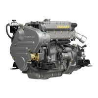
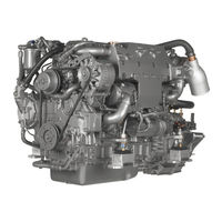
Yanmar Corporation from Japan gained fame on the whole planet as a manufacturer of diesel engines. At present, this company is rightfully considered the leader in terms of the
volume of not only the production of such products, but also sales.
Japanese corporation Yanmar also produces the final products. In this case, we are talking about Yanmar water pumps, boat engines, generators (power stations), garden tractors and other things
that are installed by the engines of our own production.
History of the company Yanmar began in 1912 in Japan. Only then the company was called Yamaoka Hatsudoki Kosakusho (Yamaoka Hatsudoki Kosakuse). Brand Yanmar appeared only nine years after the
company was founded. In the year 1921.
The name of the company Yanmar is easy to explain. It comes from the word oni-yanma, which in translation means «dragonfly wings». The fact is that for Japanese the dragonfly is considered a
symbol of a rich harvest. So, in this case, the brand was supposed to personify the image of the company, which is ready to dynamically develop. The angular form of the logo is evidence that the
company is determined to meet the future, which is marked by leadership and technological progress. Corporate red color is a symbol of innovative spirit.
In 1933, the engineers of the Japanese company Yamaoka Hatsudoki Kosakusho successfully developed a diesel internal combustion engine, which was then very compact. The engine was not just a
prototype. It began to be released serially. Moreover, it very quickly found application in the manufacture of a variety of products.
Since the mid-1930s and for the next ten years, the company has opened several Yanmar diesel engine manufacturing enterprises throughout the island state. One plant — for example, in the city of
Nagahama. Another plant is in the city of Amagasaki.
In 1947, the company went on the road, which was supposed to work out a new direction of activity — the production of small diesel engines, which were intended for fishing vessels.
In 1952, the first common logo of the Yanmar Group appeared. It was based on the fact that the name of the company is written in Latin letters — YANMAR. The logo used now was developed in 1993.
It was necessary for this because many changes were made that were aimed at meeting modern requirements. Changes in production have underlined and changes in the logo.
Mini excavators YANMAR:
- YANMAR SV08-1
- YANMAR SV100
- YANMAR ViO15
- YANMAR ViO15-2
- YANMAR ViO15-2A
- YANMAR ViO20-2
- YANMAR ViO20-3
- YANMAR ViO27-2
- YANMAR ViO27-3
- YANMAR ViO35-2
- YANMAR ViO75A
- YANMAR ViO35-3
- YANMAR ViO40-2A
- YANMAR ViO45-5
- YANMAR ViO50-2A
- YANMAR ViO55-5
- YANMAR ViO70
- YANMAR ViO75A
- YANMAR B7-5A
- YANMAR CBL40
- YANMAR IN 08-3
- YANMAR В22-2В-Р
- YANMAR В22-2В-С
- YANMAR В27-2В-Р
- YANMAR В27-2В-С
- YANMAR В37-2В-Р
- YANMAR В37-2В-С
- YANMAR В502В-Р
- YANMAR В502В-С
Backhoe loaders YANMAR:
- YANMAR CBL40
- YANMAR C50R-3A
Loaders YANMAR:
- YANMAR V3-6
- YANMAR V4-6
Crawler mini dumpers YANMAR:
- YANMAR C12R-A
- YANMAR C30R
- YANMAR C50R-3A
-
Contents
-
Table of Contents
-
Troubleshooting
-
Bookmarks
Quick Links
Service Manual
4TNV98 & 4TNE98 Diesel Engine
D20S-5, D25S-5, D30S-5, D33S-5, D35C-5
(4TNV98 : EM0Q3, EM0Q4, EM0Q5)
D20S-5, D25S-5, D30S-5, D33S-5, D35C-5
(4TNE98 : EM0QC, EM0QD, EM0QE)
D20G, D25G, D30G
(4TNE98)
SB4319E00
Jan. 2008
Chapters
-
Section 1. General Service Section 2. Periodic Maintenance Information
5 -
Table of Contents
116 -
Table of Contents
192
Troubleshooting
-
Starter Motor Troubleshooting
225 -
Special Service Tools
237 -
Troubleshooting By Measuring Compression Pressure
238 -
Quick Reference Table For Troubleshooting
241 -
Troubleshooting Charts
242
Related Manuals for Yanmar 4TNV98
Summary of Contents for Yanmar 4TNV98
-
Page 1
SB4319E00 Jan. 2008 Service Manual 4TNV98 & 4TNE98 Diesel Engine D20S-5, D25S-5, D30S-5, D33S-5, D35C-5 (4TNV98 : EM0Q3, EM0Q4, EM0Q5) D20S-5, D25S-5, D30S-5, D33S-5, D35C-5 (4TNE98 : EM0QC, EM0QD, EM0QE) D20G, D25G, D30G (4TNE98) -
Page 3: Important Safety Information
If a tool, procedure, work method or operating technique not specifically recommended by DOOSAN is used, you must satisfy yourself that it is safe for you and others. You should also ensure that the product will not be damaged or made unsafe by the operation, lubrication, maintenance or repair procedures you choose.
-
Page 5: Table Of Contents
Engine General Specifications ….21 Cylinder Head ……..66 Principal Engine Specifications……22 Intake / Exhaust Valve and Guide Cont… 67 4TNV98 EPA Tier 2 ……22 Push Rod……….68 4TNE98 EPA Tier 3 ……23 Rocker Arm and Shaft ……68 Engine Service Standards……..
-
Page 6
Removal of Fuel Injection Pump … 148 Judgement Criteria on Atomization Installation of Fuel Injection Pump ..152 Condition ……….199 Checking and Adjusting Fuel Injection Timing..157 Installation of Fuel Injectors….200 Determining the Fuel Injection Timing 4TNV98 & 4TNE98 Diesel Engine Index… -
Page 7
Reassembly of Starter Motor ….232 Check Pinion Projection Length…. 233 No-Load Test ……..234 Installation of Starter Motor….234 Section 8. TROUBLESHOOTING Special Service Tools ……..235 Troubleshooting By Measuring Compression Pressure …………236 Compression Pressure Measurement 4TNV98 & 4TNE98 Diesel Engine Index… -
Page 9: Component Identification
(7) Drain Plug (Engine Oil) (8) Engine Oil Filter Figure 4-1a (9) Dipstick (EngineOil) (10) Engine Coolant Pump (11) Alternator (12) Glow Plug (13) V-Belt (14) Crankshaft V-Pulley (15) Starter Motor 4TNV98 & 4TNE98 Diesel Engine Section 1. General Service Information…
-
Page 10: Location Of Labels
Maintenance Schedule section of this manual. Figure 4-2 The typical location of the emission control information label shown (Figure 4-2 (2), (3)). The typical location of the engine nameplate is shown (Figure 4-2 (1), (4)). 4TNV98 & 4TNE98 Diesel Engine Section 1. General Service Information…
-
Page 11: Emission Control Labels
Engine Family The EPA / ARB labels and the 97/68/EC label all have an Engine Family field. The following is an explanation of the Engine Family designation: (EPA and ARB) 4TNV98 & 4TNE98 Diesel Engine Section 1. General Service Information…
-
Page 12: Function Of Major Engine Components
The starter motor is powered by the battery. When you turn the key switch in the operator’s console to the START position, the starter motor Starter Motor engages with the ring gear installed on the flywheel and starts the flywheel in motion. 4TNV98 & 4TNE98 Diesel Engine Section 1. General Service Information…
-
Page 13: Function Of Cooling System Components
By letting the engine warm up as quickly as possible, the thermostat reduces engine wear, deposits and emissions. 4TNV98 & 4TNE98 Diesel Engine Section 1. General Service Information…
-
Page 14: Diesel Fuel
Diesel Fuel • The total aromatics content should not exceed 35% by volume. Less than 30% is preferred. Diesel Fuel Specifications • The PAH (polycyclic aromatic hydrocarbons) content should be below 10% by volume. Diesel fuel should comply with the following •…
-
Page 15: Filling The Fuel Tank
NEVER place diesel fuel or other flammable material such as oil, hay or dried grass close to the engine during engine operation or shortly after shutdown. Failure to comply will result in death or serious injury. 4TNV98 & 4TNE98 Diesel Engine Section 1. General Service Information…
-
Page 16
(3)) and stop fueling when the gauge shows the fuel tank is full. NEVER overfill the fuel tank. 4. Replace the fuel cap (Figure 4-3, (1)) and hand tighten. Over-tightening the fuel cap will damage 4TNV98 & 4TNE98 Diesel Engine Section 1. General Service Information… -
Page 17: Priming The Fuel System
6. NEVER use the starter motor to crank the engine in order to prime the fuel system. This may cause the starter motor to overheat and damage the coils, pinion and/or ring gear. Figure 4-4 4TNV98 & 4TNE98 Diesel Engine Section 1. General Service Information…
-
Page 18: Engine Oil
• ACEA Service Categories E-3, E-4, and E-5 • JASO Service Category DH-1 Definitions • API Classification (American Petroleum Institute) • ACEA Classification (Association des Constructeurs Européens d’Automobilies) • JASO (Japanese Automobile Standards Organization) Figure 4-4a 4TNV98 & 4TNE98 Diesel Engine Section 1. General Service Information…
-
Page 19: Checking Engine Oil
Yanmar engines. Dipstick Upper Engine Model Limit / Lower Limit 11.1 / 6.3 qt 4TNV98 (10.5 / 6.0 L) 9.7 / 7.6 qt 4TNE98 (9.2 / 7.2 L) Figure 4-5 4TNV98 & 4TNE98 Diesel Engine Section 1. General Service Information…
-
Page 20: Engine Coolant
BURN HAZARD! Wait until the engine cools before you drain the engine coolant. Hot engine coolant may splash and burn you. Failure to comply could result in death or serious injury. 4TNV98 & 4TNE98 Diesel Engine Section 1. General Service Information…
-
Page 21: Engine Coolant Specifications
• NEVER mix extended or long life coolants and conventional (green) coolants. • NEVER mix different types and / or colors of extended life coolants. • Replace the coolant every 1000 engine hours or once a year. Figure 4-7 4TNV98 & 4TNE98 Diesel Engine Section 1. General Service Information…
-
Page 22: Engine Coolant Capacity (Typical)
(Figure 4-6, (6)). If the engine coolant is not at the FULL (HOT) mark (Figure 4-6, (6)), add additional engine coolant to the reserve tank to bring the level to the FULL (HOT) mark. 4TNV98 & 4TNE98 Diesel Engine Section 1. General Service Information…
-
Page 23: Engine General Specifications
• With Cooling Fan, Air Cleaner, Muffler: Yanmar Standard • After Engine Break-In Period; Output Allowable Deviation: ± 3% • 1 PS = 0.7355 kW • 1 hp SAE (Society of Automotive Engineers) = 0.7457 kW 4TNV98 & 4TNE98 Diesel Engine Section 1. General Service Information…
-
Page 24: Principal Engine Specifications
*** Engine oil capacity for a “Deep Standard” oil pan. Refer to the operation manual provided by the driven machine manufacturer for the actual engine oil capacity of your machine. 4TNV98 & 4TNE98 Diesel Engine Section 1. General Service Information…
-
Page 25: Tne98 Epa Tier 3
** The Intake and Exhaust condition of Max. Rated output are Air Intake Restriction : 250mmAq Exhaust Gas Restriction : 1000mmAq ***The detail specifications are refer to the Specification document which is agreed between both engineering. 4TNV98 & 4TNE98 Diesel Engine Section 1. General Service Information…
-
Page 26: Engine Service Standards
157°F — 163°F Option Above See Thermostat (70°C — 73°C) Thermostat 185°F (85°C) on page 207 0.39 in (10 mm) 176°F — 183°F Standard (80°C — 84°C) above 203°F (95°C) 4TNV98 & 4TNE98 Diesel Engine Section 1. General Service Information…
-
Page 27: Tightening Torques For Standard Bolts And Nuts
“7” head. (JIS strength classification: 7T) Apply 60% torque to bolts that are not listed. Apply 80% torque when tightened to aluminum alloy. 4TNV98 & 4TNE98 Diesel Engine Section 1. General Service Information…
-
Page 28
4.0 5.0 kgf·m) 36 — 43 ft·lb (49.0 — 58.8 N·m, 5.0 — 6.0 kgf·m) NOTE: Torque values shown in this manual are for clean, non-lubricated fasteners unless otherwise specified. 4TNV98 & 4TNE98 Diesel Engine Section 1. General Service Information… -
Page 29: Abbreviations And Symbols
I.D. inside diameter ° degree identification indirect injection plus inch in.Aq minus inches Aqueous (water) in.Hg inches Mercury ± plus or minus in.-lb inch pound Ω joule μ micro percent 4TNV98 & 4TNE98 Diesel Engine Section 1. General Service Information…
-
Page 30: Unit Conversions
1.3410221 = hp 0.2248 = lbf 0.1020 = kgf 2.2050 = lbf 9.8070 Units of Temperature °F = (1.8 x °C) + 32 °C = 0.556 x (°F — 32) 4TNV98 & 4TNE98 Diesel Engine Section 1. General Service Information…
-
Page 31: Section 2. Periodic Maintenance
NEVER overfill the fuel tank. Fill fuel tank. Store containers containing fuel in a well-ventilated area, away from any combustibles or sources of ignition. Failure to comply will result in death or serious injury. 4TNV98 & 4TNE98 Diesel Engine Section 2. Periodic Maintenance…
-
Page 32
Diesel fuel is flammable and explosive under certain conditions. Failure to comply will result in death or serious injury. NEVER use diesel fuel as a cleaning agent. Failure to comply will result in death or serious injury. 4TNV98 & 4TNE98 Diesel Engine Section 2. Periodic Maintenance… -
Page 33
Wear eye protection. The fuel system is under pressure and fuel could spray out when you remove any fuel system component. Failure to comply will result in death or serious injury. 4TNV98 & 4TNE98 Diesel Engine Section 2. Periodic Maintenance… -
Page 34
Check before starting the engine that any tools or shop rags used during maintenance have been removed from the area. Failure to comply could result in death or serious injury. 4TNV98 & 4TNE98 Diesel Engine Section 2. Periodic Maintenance… -
Page 35
These surfaces are extremely hot while the engine is operating and could seriously burn you. Failure to comply could result in death or serious injury. 4TNV98 & 4TNE98 Diesel Engine Section 2. Periodic Maintenance… -
Page 36
NEVER check for a fuel leak with your hands. ALWAYS use a piece of wood or cardboard. Have your authorized Yanmar industrial engine dealer or distributor repair the damage. Failure to comply could result in death or serious injury. 4TNV98 & 4TNE98 Diesel Engine Section 2. Periodic Maintenance… -
Page 37
Failure to comply could result in death or serious injury. 4TNV98 & 4TNE98 Diesel Engine Section 2. Periodic Maintenance… -
Page 38
Be sure to use Yanmar NEVER remove primary strainer genuine replacement parts. equipped) from the fuel tank filler port. If removed, dirt and debris could get into the fuel system causing it to clog. 4TNV98 & 4TNE98 Diesel Engine Section 2. Periodic Maintenance… -
Page 39
CAUTION NEVER hold the key in the START position for longer than 15 seconds or the starter motor will overheat. 4TNV98 & 4TNE98 Diesel Engine Section 2. Periodic Maintenance… -
Page 40
ALWAYS keep the oil level between the upper and lower lines on the oil cap/dipstick. Periodic maintenance prevents unexpected downtime, reduces the number of accidents due to poor machine performance and helps extend the life of the engine. 4TNV98 & 4TNE98 Diesel Engine Section 2. Periodic Maintenance… -
Page 41
Section. restriction exceeds the above mentioned value. Consult your authorized Yanmar dealer or distributor for assistance when checking items marked with a. 4TNV98 & 4TNE98 Diesel Engine Section 2. Periodic Maintenance… -
Page 42: Introduction
EPA and ARB. Maximum Exhaust Gas Restriction shall be: EXHAUST HAZARD! NEVER operate the engine in an enclosed area • 4TNV98 : 2.22 psi (15.3 kPa; 1560mm Aq) or such as a garage, tunnel, underground room, Iess manhole ship’s…
-
Page 43: Periodic Maintenance Schedule
See Yanmar Limited Warranty in Warranty Section. Consult your authorized Yanmar dealer or distributor for assistance when checking items marked with a. 4TNV98 & 4TNE98 Diesel Engine Section 2. Periodic Maintenance…
-
Page 44
Intake and Clean or Replace Air Cleaner Element ○ ◇ Exhaust Complete Overall Visual Check Daily ○ Engine NOTE: These procedures are considered normal maintenance and are performed at the owner’s expense. 4TNV98 & 4TNE98 Diesel Engine Section 2. Periodic Maintenance… -
Page 45: Periodic Maintenance Procedures
After draining the fuel filter/water separator, be sure to tighten • Failure to comply will result in death or serious the air vent screw. injury. 0000025en 0000009en. 4TNV98 & 4TNE98 Diesel Engine Section 2. Periodic Maintenance…
-
Page 46
The fuel filter / water separator contains a sensor to detect the amount of water and contaminants. This sensor sends a signal to an indicator to alert the operator. Drain the fuel filter / water separator as follows: Figure 5-1 4TNV98 & 4TNE98 Diesel Engine Section 2. Periodic Maintenance… -
Page 47: Daily
Failure to comply could result in death or the ground, or into ground water or waterways. serious injury. Failure follow these procedures seriously harm the environment. 4TNV98 & 4TNE98 Diesel Engine Section 2. Periodic Maintenance…
-
Page 48
Applicable Engine Oil Filter Part No. 4TNV98 A408065 4TNE98 A408065 Figure 5-1 6. Remove the oil drain plug (Figure 5-2, (1)) from the engine oil pan. Allow oil to drain. 4TNV98 & 4TNE98 Diesel Engine Section 2. Periodic Maintenance… -
Page 49
Figure 5-4 Figure 5-3 9. Reinstall the oil filler cap (Figure 5-3, (4)). If any engine oil is spilled, wipe it away with a clean cloth. 4TNV98 & 4TNE98 Diesel Engine Section 2. Periodic Maintenance… -
Page 50: Every 50 Hours Of Operation
3. Tighten the V-belt to the proper tension. There must be clearance (Figure 5-6, (1)) between the 4TNV98 & 4TNE98 (For China) Engine V-belt and the bottom of the pulley groove. If there is no clearance (Figure 5-6, (2)) between…
-
Page 51
/ water separators are page 15. equipped with a sensor to detect the amount of contaminants. This sensor sends a signal to an 7. Check for leaks. indicator to alert the operator. 4TNV98 & 4TNE98 Diesel Engine Section 2. Periodic Maintenance… -
Page 52
If the engine still will not start after charging, have your authorized Yanmar industrial engine dealer or distributor check the battery and the engine’s starting system. 4TNV98 & 4TNE98 Diesel Engine Section 2. Periodic Maintenance… -
Page 53: Every 250 Hours Of Operation
4. Drain the tank until clean diesel fuel with no water and dirt flows out. Reinstall and tighten the drain plug firmly. 5. Reinstall the fuel cap. 6. Check for leaks. 4TNV98 & 4TNE98 Diesel Engine Section 2. Periodic Maintenance…
-
Page 54
NEVER use high-pressure water or compressed air at greater than 28 psi (193 kPa; 19 686 mmAq) or a wire brush to clean the radiator fins. Radiator fins damage easily. 4TNV98 & 4TNE98 Diesel Engine Section 2. Periodic Maintenance… -
Page 55
(4)) and adjust the cable so the governor lever Failure to comply may result in minor or makes proper contact with the high / low idle moderate injury. speed limit screw. 4TNV98 & 4TNE98 Diesel Engine Section 2. Periodic Maintenance… -
Page 56: Every 500 Hours Of Operation
Failure follow these procedures seriously harm the environment. NEVER operate the engine with the air cleaner element(s) removed. This may allow foreign material to enter the engine and damage it. 4TNV98 & 4TNE98 Diesel Engine Section 2. Periodic Maintenance…
-
Page 57
DANGER seriously harm the environment. 4TNV98 & 4TNE98 (for D25G) Only FIRE AND EXPLOSION HAZARD! Replace the fuel filter at specified intervals to Diesel fuel is flammable and explosive under prevent contaminants from adversely affecting the certain conditions. -
Page 58
1. Stop the engine and allow it to cool. 2. Close all fuel cocks in fuel line. 3. Disconnect the fuel filter sensor connector (Figure 5-14a, (1)). Figure 5-15 9. Set the drain plug aside for reinstallation. 4TNV98 & 4TNE98 Diesel Engine Section 2. Periodic Maintenance… -
Page 59
Failure to comply will result in death or serious 20. Prime the fuel system. See Priming the Fuel injury. System on page 15. 21. Check for fuel leaks. Applicable Fuel Filter Part No. (Figure 5-14, (2)) 4TNE98 A409559 4TNV98 & 4TNE98 Diesel Engine Section 2. Periodic Maintenance… -
Page 60
12. Close the drain cock. Reconnect the sensor wire if equipped. 13. Open the fuel cock (Figure 5-15, (3)). 14. Prime the fuel system. See Priming the Fuel System on page 15. 15. Check for leaks. Figure 5-15 4TNV98 & 4TNE98 Diesel Engine Section 2. Periodic Maintenance… -
Page 61: Every 1000 Hours Of Operation
2. Remove the radiator cap (Figure 5-16, (1)). 3. Remove the drain plug or open the drain cock (Figure 5-16, (2)) at the lower portion of the radiator and drain the engine coolant. 4TNV98 & 4TNE98 Diesel Engine Section 2. Periodic Maintenance…
-
Page 62
4. Drain the coolant from the engine block. • On models not equipped with an oil cooler, remove the coolant drain plug (Figure 5-17, (1)) from the engine block. Figure 5-17 4TNV98 & 4TNE98 Diesel Engine Section 2. Periodic Maintenance… -
Page 63: Every 1500 Hours Of Operation
3. Inspect the diaphragm for tears. Inspect the spring for distortion. Replace components if necessary. 4. Reinstall the diaphragm, diaphragm plate, spring and diaphragm cover. Tighten the diaphragm bolts to specified torque. 4TNV98 & 4TNE98 Diesel Engine Section 2. Periodic Maintenance…
-
Page 64: Every 2000 Hours Of Operation
NEVER dispose hazardous materials irresponsibly by dumping them into a sewer, on the ground, or into ground water or waterways. Failure follow these procedures seriously harm the environment. 4TNV98 & 4TNE98 Diesel Engine Section 2. Periodic Maintenance…
-
Page 65: Before You Begin Servicing
Section 3. ENGINE Before You Begin Servicing WARNING WARNING FUME / BURN HAZARD! To prevent possible eye injury, always wear Always read follow safety related SAFETY GLASSES while servicing the engine. precautions found on containers of hazardous substances like parts cleaners, primers, sealants and sealant removers.
-
Page 66
Identify all parts and their location using an appropriate method. It is important that all parts are returned to the same position during the reassembly process. 4TNV98 & 4TNE98 Diesel Engine Section 3. Engine… -
Page 67
CAUTION Do not allow the honing tool to operate in one position for any length of time. Damage to the cylinder wall will occur. Keep the tool in constant up-and-down motion. 4TNV98 & 4TNE98 Diesel Engine Section 3. Engine… -
Page 68: Introduction
(1.0 mm) Inspection Valve Sink of Intake 0.024 — 0.032 in. 0.043 in. Exhaust (0.6 — 0.8 mm) (1.1 mm) Exhaust Valves on Intake 120° Valve Seat Angle page 95. Exhaust 90° 4TNV98 & 4TNE98 Diesel Engine Section 3. Engine…
-
Page 69: Intake / Exhaust Valve And Guide Cont
Valve Guide Projection From Cylinder Head Valve (14.7 – 15.0 mm) Guides on page 98. Assembly of 0.66 — 0.70 in. Valve Stem Seal Projection From Cylinder Head Valve (16.7 – 17.0 mm) Guides on page 98. 4TNV98 & 4TNE98 Diesel Engine Section 3. Engine…
-
Page 70: Push Rod
(43.400 — 43.600 mm) (43.150 mm) Camshaft on Cam Lobe Height page 125. 1.6707 — 1.6758 in. 1.6608 in. 4TNE98 (42.435– 42.565 mm) (42.185 mm) Shaft Outside Diameter / Bearing Inside Diameter 4TNV98 & 4TNE98 Diesel Engine Section 3. Engine…
-
Page 71: Idler Gear Shaft And Bushing
Pump Gear and PTO Gear (0.08 — 0.14 mm) (0.16 mm) Timing Gear Backlash on 0.0035 — 0.0059 in. 0.0067 in. Lubricating Oil Pump Gear page 112. (0.09 — 0.15 mm) (0.17 mm) 4TNV98 & 4TNE98 Diesel Engine Section 3. Engine…
-
Page 72: Crankshaft And Piston Specifications
0.0051 — 0.0091 in. 0.0110 in. 4TNV98 Removal of (0.13 — 0.23 mm) (0.28 mm) Crankshaft End Play Crankshaft 0.0043 — 0.0083 in. 0.0110 in. on Page 4TNE98 (0.11 — 0.21 mm) (0.28 mm) 118. 4TNV98 & 4TNE98 Diesel Engine Section 3. Engine…
-
Page 73: Piston
(2.950 mm) Oil Ring 0.0010 — 0.0024 in. 0.0071 in. Side Clearance (0.025 — 0.060 mm) (0.180 mm) 0.0098 — 0.0177 in. 0.0217 in. End Gap (0.250 — 0.450 mm) (0.550 mm) 4TNV98 & 4TNE98 Diesel Engine Section 3. Engine…
-
Page 74: Connecting Rod
0.4715 — 0.4720 in. 0.4707 in. Tappet Stem Outside Diameter Tappets on page (11.975 — 11.990 mm) (11.955 mm) 124. 0.0004 — 0.0017 in. 0.0033 in. Oil Clearance (0.010 — 0.043 mm) (0.083 mm) 4TNV98 & 4TNE98 Diesel Engine Section 3. Engine…
-
Page 75: Cylinder Block Specifications
M10 x 1.0 mm (53.9 — 58.8 N·m; Applied 5.5 — 6.0 kgf·m) 137 — 152 ft·lb Flywheel Bolt M14 x 1.5 mm (186.2 — 205.8 N·m; Applied 19 — 21 kgf·m) 4TNV98 & 4TNE98 Diesel Engine Section 3. Engine…
-
Page 76
M6 x 1.0 mm (7.8 — 9.8 N·m; Not Applied Line Joint Bolt 0.8 — 1.0 kgf·m) See Tightening Torques for Standard Bolts and Nuts on page 23 for standard hardware torque values. 4TNV98 & 4TNE98 Diesel Engine Section 3. Engine… -
Page 77: Special Service Tools
Valve Spring) Model 0.598 0.827 0.472 0.465 2.559 0.157 4TNV98 (15.2 (11.8 Stem Seal Installer (for Installing Valve Stem Seal) 0.638 0.866 0.531 0.669 2.560 0.157 4TNE98 (16.2 (13.5 (17.0 Locally Manufactured 4TNV98 & 4TNE98 Diesel Engine Section 3. Engine…
-
Page 78
The Piston Insertion Tool is Applicable for 2.362 — 4.921 in. (For Installing (60 — 125 mm) Diameter Pistons Piston) Piston Ring Expander (For Removal Available Locally / Installation of Piston Ring) Crankshaft Pulley Locally Manufactured Installing Tool 4TNV98 & 4TNE98 Diesel Engine Section 3. Engine… -
Page 79: Measuring Instruments
For measuring outside diameters, depth, Calipers Locally Available thickness and width Depth Locally Available For measuring of valve recession Micrometer For measuring valve spring inclination Square Locally Available and straightness of parts 4TNV98 & 4TNE98 Diesel Engine Section 3. Engine…
-
Page 80
Type periphery of the revolving shaft Fuel High This measures the revolution Pressure Pipe regardless of the center or periphery Clamp Type of the revolving object 4TNV98 & 4TNE98 Diesel Engine Section 3. Engine… -
Page 81
Circuit Tester continuity of electrical circuits For measuring compression Compression Gauge Kit pressureGauge Set Part No. TOL- 97190080 Adapter for direct injection 2-valve New Comperssion Test cylinder headAdapter Part No. 119802- Adaptor 92950 4TNV98 & 4TNE98 Diesel Engine Section 3. Engine… -
Page 82: Cylinder Head
Cylinder Head Cylinder Head Components 4TNV98 Engine Figure 6-36 4TNV98 & 4TNE98 Diesel Engine Section 3. Engine…
-
Page 83
29) Valve Bridge. 30) Valve Bridge Seat. 31) Valve Adjusting Screw Lock Nut (Secondary). 32) Valve Adjusting Screw (Secondary). 33) Push Rod. 34) Rocker Arm Shaft. 35) Crankcase Breather Components. 36) Valve Cover. 4TNV98 & 4TNE98 Diesel Engine Section 3. Engine… -
Page 84: Disassembly Of 4-Valve Cylinder Head
6-38, (9)). 8. Remove the exhaust manifold bolts (Figure 6-38, (7)). Remove the exhaust manifold (Figure 6-38, (6)) with the turbocharger attached. Discard the exhaust manifold gasket. (Figure 6-38, (5)). Figure 6-37 4TNV98 & 4TNE98 Diesel Engine Section 3. Engine…
-
Page 85
3 o’clock position in the valve cover opening to insert the screwdriver. Figure 6-39 3. Remove the valve cover nuts (Figure 6-40, (4)). 4. Remove the O-ring (Figure 6-40, (5)) on each valve cover nut. 4TNV98 & 4TNE98 Diesel Engine Section 3. Engine… -
Page 86
Components for all remaining cylinders are assembled in the same order. 3. Remove the valve adjusting screw (Figure 6-42, (2)) and the lock nut (Figure 6-42, (3)) from the rocker arms. Figure 6-41 4TNV98 & 4TNE98 Diesel Engine Section 3. Engine… -
Page 87
1. Place the cylinder head on the work bench with prevent damage to the combustion surface. the combustion side down. 2. Using the valve spring compressor tool, compress one of the valve springs (Figure 6-45). Figure 6-45 4TNV98 & 4TNE98 Diesel Engine Section 3. Engine… -
Page 88
8. Turn the cylinder head so the exhaust port side faces down. Remove the intake and exhaust valves (Figure 6-46, (5)) from the cylinder head. 9. Remove the valve stem seals (Figure 6-46, (4)). 4TNV98 & 4TNE98 Diesel Engine Section 3. Engine… -
Page 89: Tne98 Engine
4TNE98 Engine Figure 6-1 4TNV98 & 4TNE98 Diesel Engine Section 3. Engine…
-
Page 90
23) Rocker Arm Shaft Spring 24) Support Bracket Stud 25) Support Bracket 26) Rocker Arm 27) Rocker Arm Shaft Retaining Ring 28) Valve Adjusting Screw Lock Nut 29) Valve Adjusting Screw 30) Support Bracket Nut 4TNV98 & 4TNE98 Diesel Engine Section 3. Engine… -
Page 91: Disassembly Of Cylinder Head
3. Remove the water pump from the engine. See Disassembly of Engine Coolant Pump on 205. 4. Remove the fuel injectors from the cylinder head. See Removal of the Fuel Injectors on page 196. 4TNV98 & 4TNE98 Diesel Engine Section 3. Engine…
-
Page 92
Reverse this process when you reinstall the rocker arm shaft into the support brackets. NOTE : Mark the rocker arms so they can be reinstalled with the original matching valve and pushrod. 4TNV98 & 4TNE98 Diesel Engine Section 3. Engine… -
Page 93
Position the cylinder head on the work bench to prevent damage to the combustion surface. Figure 6-10 3. Remove the valve keepers (Figure 6-11, (2)) and valve cap (Figure 6-10, (1)) from the end of the valve. 4TNV98 & 4TNE98 Diesel Engine Section 3. Engine… -
Page 94: Cleaning Of Cylinder Head Components
Remove the intake and exhaust valves (Figure 6-11, (6)) from the cylinder head. Removal of Valve Guides 1. Using a drift pin and hammer, drive the valve guides (Figure 6-12, (1)) out of the cylinder head. 4TNV98 & 4TNE98 Diesel Engine Section 3. Engine…
-
Page 95
(Figure 6-49) are within the specified limits. See Rocker Arm and Shaft on page 68 for the service limit. 2. Inspect the contact areas (Figure 6-49, (1)) for excessive wear or damage. 4TNV98 & 4TNE98 Diesel Engine Section 3. Engine… -
Page 96
(combustion side up) on the bench. Use a straight edge and feeler gauge to measure cylinder head distortion (Figure 6-52). Measure diagonally and along each side. See Cylinder Head on page 66 for the service limit. Figure 6-50 Figure 6-52 4TNV98 & 4TNE98 Diesel Engine Section 3. Engine… -
Page 97
(Figure 6-56). See Cylinder Head on page 66 for the service limit. Figure 6-55 NOTE : 2-Valve cylinder head is shown. 4-Valve cylinder head is similar. 4TNV98 & 4TNE98 Diesel Engine Section 3. Engine… -
Page 98
40° stone to make the seat diameter larger. Once the seat location has been corrected, grind and lap the seat angle (Figure 6-58, (1)) to specification. See Cylinder Head on page 66 for specifications. 4TNV98 & 4TNE98 Diesel Engine Section 3. Engine… -
Page 99
(Figure 6-61, Spring on page 68 for the service limit. (3)). See Rocker Arm and Shaft on page 68 for the service limit. Figure 6-59 Figure 6-61 4TNV98 & 4TNE98 Diesel Engine Section 3. Engine… -
Page 100: Reassembly Of Cylinder Head
1. Oil the lip of the valve stem seal (Figure 6-64, (2)). Using the valve stem seal installation tool (Figure 6-64, (1)), install a new valve stem seal on each of the valve guides (Figure 6-64, (3)). 4TNE98 Engine Figure 6-64 Figure 6-62 4TNV98 & 4TNE98 Diesel Engine Section 3. Engine…
-
Page 101
6. Using the valve spring compressor tool, compress the valve spring. 7. Insert the valve keepers (Figure 6-66, (1)) and slowly release the tension in the valve spring. Repeat the steps on all the remaining valves. 4TNV98 & 4TNE98 Diesel Engine Section 3. Engine… -
Page 102
Tighten in the sequence shown in (Figure 6-68). See Special Torque Chart on page 73 for specification. First Step 1/2 of final torque Second Step Final torque 4TNV98 & 4TNE98 Diesel Engine Section 3. Engine… -
Page 103
3. Lubricate the rocker arm shaft. Slide the rocker arm supports (Figure 6-72, (6)), wave washers (Figure 6-72, (7)), rocker arms Figure 6-69 (Figure 6-72, (8)), and fuel injector retainers (Figure 6-72, (4)) onto the shaft. 4TNV98 & 4TNE98 Diesel Engine Section 3. Engine… -
Page 104
Tighten the rocker arm shaft alignment screw. 6. Align the push rods with their respective rocker arms and adjust the valve lash. (See Measuring and Adjusting Valve Clearanceon page 104.) 4TNV98 & 4TNE98 Diesel Engine Section 3. Engine… -
Page 105
6. Reinstall the intake manifold using a new gasket. Tighten the bolts to specification. 7. Reconnect the fuel injector return hose and fuel Figure 6-33 injection pump coolant hoses. 8. Reinstall the high-pressure fuel line grommets into the valve cover. 4TNV98 & 4TNE98 Diesel Engine Section 3. Engine… -
Page 106: Measuring And Adjusting Valve Clearance
4-Cylinder Engines Cylinder No. Valve Intake Exhaust Intake Exhaust Intake Exhaust Intake Exhaust No. 1 Cylinder at • • • • TDC Compression No. 4 Cylinder at • • • • TDC Compression 4TNV98 & 4TNE98 Diesel Engine Section 3. Engine…
-
Page 107: Tne98 Engine
No. 1 cylinder. Select and adjust the cylinder where the piston is nearest to the top dead center after turning, and make adjustment for other cylinders in the order of firing by turning the crankshaft. 4TNV98 & 4TNE98 Diesel Engine Section 3. Engine…
-
Page 108: Tnv98 Engine
(Position where both the intake and exhaust valves are closed.) 3. Make sure there is clearance (Figure 6-77, (5)) between the valve bridge (Figure 6-77, (1)) and the rocker arm (Figure 6-77, (3)). Figure 6-79 4TNV98 & 4TNE98 Diesel Engine Section 3. Engine…
-
Page 109
(Figure 6-82, (1)) of the correct thickness (See Adjustment Specifications on page6-6) between the rocker arm (Figure 6-82, (2)) and valve bridge (Figure 6-82, (3)). Record the results and use this value as an indication of wear. 4TNV98 & 4TNE98 Diesel Engine Section 3. Engine… -
Page 110
13. Apply oil to the contact surface between the adjusting screw and push rod. 14. Rotate the crankshaft to measure and adjust the set of valves. Continue until all valves are measured and adjusted. 4TNV98 & 4TNE98 Diesel Engine Section 3. Engine… -
Page 111: Crankshaft And Camshaft Components
Crankshaft and Camshaft Components Figure 6-84 4TNV98 & 4TNE98 Diesel Engine Section 3. Engine…
-
Page 112
(33) Wrist Pin Bushing. (34) Circlip . (35) Wrist Pin. (36) Piston. (37) Oil Ring. (38) Second Compression Ring. (39) Top Compression Ring. (40) Crankshaft Rear Seal. (41) Crankshaft Rear Seal Housing. 4TNV98 & 4TNE98 Diesel Engine Section 3. Engine… -
Page 113: Disassembly Of Engine
7. Drain the engine oil into a suitable container. Remove the oil filter. 8. Remove the cylinder head. See 4-Valve Cylinder 4TNV98 & 4TNE98 Diesel Engine Section 3. Engine…
-
Page 114
Figure 6-87 2. Rotate the idler gear back and forth to check the idler gear-to-crankshaft gear backlash. The total indicator reading is the backlash. Record the measurement. 4TNV98 & 4TNE98 Diesel Engine Section 3. Engine… -
Page 115
1. Invert the engine (oil pan up) on the engine stand. not remove the camshaft gear unless it or the camshaft is damaged and requires replacement. 2. Remove the oil pan (Figure 116, (1)). See Removal of Camshaft on page 114. 4TNV98 & 4TNE98 Diesel Engine Section 3. Engine… -
Page 116
• Method B : Use a feeler gauge to measure the clearance between the thrust plate (Figure 6-93, (1)) and front camshaft bearing (Figure 6-93, (2)). See Thrust Bearing on page 70 for the service limit. Figure 6-91 Figure 6-93 4TNV98 & 4TNE98 Diesel Engine Section 3. Engine… -
Page 117: Figure
Use a knife-edge puller and a press Figure 6-95 to remove the gear. The gear is a shrink-fit and will need to be heated to 356° — 392°F (180° — 200°C) to remove. 4TNV98 & 4TNE98 Diesel Engine Section 3. Engine…
-
Page 118: Figure
2. Measure bearing oil clearance prior to removing engine is inverted. Rotate the engine so the the pistons and connecting rods to determine connecting rods are horizontal before removing the extent of wear. Record the measurements. connecting rod caps. 4TNV98 & 4TNE98 Diesel Engine Section 3. Engine…
-
Page 119
(f) Compare the width of the flattened PLASTIGAGE to the graduation marks on the package (Figure 6-99, (1)). The mark that most closely matches the width of the flattened PLASTIGAGE will indicate the bearing oil clearance. 4TNV98 & 4TNE98 Diesel Engine Section 3. Engine… -
Page 120
• Method A : Install a dial gauge (Figure 6-102, (1)) on the cylinder block. Move the crankshaft (Figure 6-102, (2)) in and out to measure the end play. Record the measurement. Figure 6-102 4TNV98 & 4TNE98 Diesel Engine Section 3. Engine… -
Page 121: Method B : Use A Feeler Gauge To Measure The
Record the measurements. (a) Wipe oil from the bearing insert and crankshaft journal surfaces. (b) Place a piece of PLASTIGAGE (Figure 6-105, (1)) along the full width of each bearing insert. 4TNV98 & 4TNE98 Diesel Engine Section 3. Engine…
-
Page 122: Components
Replacement of Crankshaft Oil Seals 7. Remove the bearing inserts (Figure 6-104, (1)) 1. Remove the seal (Figure 6-108, (2)) from the and thrust bearings (Figure 6-104, (2)). cover (Figure 6-108, (1)). 4TNV98 & 4TNE98 Diesel Engine Section 3. Engine…
-
Page 123
Gasket No. 1212 to the outside diameter of a new oil seal (Figure 6-109, (2)), and install in the housing. Apply lithium grease to the lip of the seal. Figure 6-110 Figure 6-109 4TNV98 & 4TNE98 Diesel Engine Section 3. Engine… -
Page 124
See Piston on page 71 for specifications. Figure 6-113 8. Using a micrometer, measure the thickness of each piston ring. See Piston on page 71 for specifications. Record the measurements. Figure 6-111 4TNV98 & 4TNE98 Diesel Engine Section 3. Engine… -
Page 125
(Figure 6-115, (2)) from the bottom of the bore. Remove the piston. Measure the end gap (Figure 6-115, (3)) of each piston ring. Record the measurements. See Piston Ring on page 71 for specifications. 4TNV98 & 4TNE98 Diesel Engine Section 3. Engine… -
Page 126
(Figure 6-117, (2)). Slight surface defects can be corrected using an oilstone. Figure 6-119 3. Rotate the crankshaft and observe runout. See Crankshaft on page 70 for specifications. Figure 6-117 4TNV98 & 4TNE98 Diesel Engine Section 3. Engine… -
Page 127
Figure 6-122 4. Measure the diameter of the gear end (Figure 6- 123, (1)), intermediate (Figure 6-123, (2)), and flywheel end (Figure 6-123, (3)) bearing journals. See Camshaft on page 68 for specifications. 4TNV98 & 4TNE98 Diesel Engine Section 3. Engine… -
Page 128: Honing And Boring
30° to 40° crosshatch pattern (Figure 6-125). This will provide the ideal surface for the proper seating of new piston rings. Figure 6-124 4TNV98 & 4TNE98 Diesel Engine Section 3. Engine…
-
Page 129: Components
Be sure to align the oil holes. IMPORTANT Solvents will not adequately remove honing residue, resulting in premature piston and ring wear. Always wash cylinders using hot, soapy water. 4TNV98 & 4TNE98 Diesel Engine Section 3. Engine…
-
Page 130
Piston to Connecting Rod Orientation — By Model Orient the piston identification mark stamped on top of the piston on the same side as the rod and cap match marks stamped on the connecting rod. 4TNV98 & 4TNE98 Diesel Engine Section 3. Engine… -
Page 131
1. Lubricate and reinstall the wrist pin (Figure 6-131, (3)) through the piston and connecting rod. 2. Reinstall the second circlip (Figure 6-131, (4)) and ensure it is securely seated in the groove. Figure 6-132 4TNV98 & 4TNE98 Diesel Engine Section 3. Engine… -
Page 132
Figure 6-133 6. Stagger the piston ring end gaps at 120° intervals (Figure 6-134, (1, 2, 3)). Do not position the top piston ring end gap in line with the wrist pin. 4TNV98 & 4TNE98 Diesel Engine Section 3. Engine… -
Page 133
• Stagger the piston ring joints at 120 intervals. Do not position the top piston ring joint inline with the piston wrist pin. The coil expander joint must be opposite the oil ring joint. Figure 6-71 4TNV98 & 4TNE98 Diesel Engine Section 3. Engine… -
Page 134
The No. 1 cap is at the flywheel end. The arrows point toward the flywheel end of the engine. Figure 6-74 4. Reinstall the main bearing caps (Figure 6-135, • Repeat these steps for the remaining pistons. (3)). 4TNV98 & 4TNE98 Diesel Engine Section 3. Engine… -
Page 135
3. Using a piston ring compressor, compress the piston rings. IMPORTANT The piston and connecting rod must be installed in the correct orientation. The orientation of the piston to the cylinder is different depending on engine model. Figure 6-136 4TNV98 & 4TNE98 Diesel Engine Section 3. Engine… -
Page 136
(1) Fuel Injection Pump Side of Engine. (2) Piston Identification Mark. (3) Embossed Mark on Connecting Rod. (4) Rod and Cap Match Marks. (5) Flywheel End of Engine. (6) Camshaft Side of Engine. 4TNV98 & 4TNE98 Diesel Engine Section 3. Engine… -
Page 137
4. Install the connecting rod bearing halves (Figure6-79,(1)) and connecting rod cap (Figure6-79,(2)). Tighten the connecting rod bolts to the specified torque. Figure 6-79 5. Install the remaining pistons in their respective cylinders. 4TNV98 & 4TNE98 Diesel Engine Section 3. Engine… -
Page 138: Components
1. Set the No. 1 piston to top dead center. and press onto the end of the camshaft. 2. Rotate the camshaft until the mark (Figure 6-144, (C)) is approximately at the 9 o’clock position. 4TNV98 & 4TNE98 Diesel Engine Section 3. Engine…
-
Page 139
See Special Torque Chart on 7. When all gears are properly aligned, tighten the page 73 for specifications. idler gear retaining bolts to specified torque. See Special Torque Chart on page 73 for specifications. 4TNV98 & 4TNE98 Diesel Engine Section 3. Engine… -
Page 140: Final Reassembly Of Engine
5. Reinstall the alternator. 6. Reconnect and adjust the throttle cable. 7. Reconnect all electrical connections. 8. Fill the engine with oil and coolant. 9. Reconnect the battery cables, negative (-) cable ast. 4TNV98 & 4TNE98 Diesel Engine Section 3. Engine…
-
Page 141: Before You Begin Servicing
PINCH HAZARD! Carefully rotate the alternator toward the cylinder block while loosening the V-belt. Failure to comply may result in minor or moderate injury. 4TNV98 & 4TNE98 Diesel Engine Section 4. Fuel System…
-
Page 142
Disassembling the high-pressure fuel injection lines from the retainers or bending any of the fuel lines will make it difficult to reinstall the fuel lines. 4TNV98 & 4TNE98 Diesel Engine Section 4. Fuel System… -
Page 143: Tnv98 Engine
MP2 pump, is used on the 3TNV82A — 4TNV88 model engines. The larger pump, the MP4 pump, which has a larger single plunger and a more aggressive cam profile, is used on the 4TNV94L- 4TNV106T model engines. 4TNV98 & 4TNE98 Diesel Engine Section 4. Fuel System…
-
Page 144: Stop Solenoid
12V at the stop solenoid connector in the by the MP fuel injection pump. correct sequence. The use of an electric fuel supply pump is required on all TNV model engines with the MP fuel injection pump. 4TNV98 & 4TNE98 Diesel Engine Section 4. Fuel System…
-
Page 145: Fuel System Specifications
Not Applied 2.3-2.9 kgf·m) 30-33 ft·lb Fuel Injector Nozzle Case Nut (39.2-44.1 N·m; Not Applied 4-4.5 kgf·m) 30-33 ft·lb Fuel Injection Pump 4TNV98 (40-45 N·m; Not Applied Plunger Plug 4.1-4.6 kgf·m) 4TNV98 & 4TNE98 Diesel Engine Section 4. Fuel System…
-
Page 146: Test And Adjustment Specifications
** Fuel injector identification is critical as each engine has a unique fuel injection pressure. The fuel nozzle is specifically matched to the fuel injector by engine model and / or engine speed. 4TNV98 & 4TNE98 Diesel Engine Section 4. Fuel System…
-
Page 147: Special Service Tools
* These special service tools may also be available as an “MP Fuel Injection Pump Special Tool Set”, under a different part number, in territories serviced by Yanmar America and Yanmar Europe. Contact your authorized Yanmar dealer or distributor for details. 4TNV98 & 4TNE98 Diesel Engine Section 4. Fuel System…
-
Page 148: Fuel System Diagram
(12) Engine Crankcase. (13) Tappet. (14) High Pressure Gallery. (15) Overflow Orifice. (16) Accumulator. (17) Timer Piston. (18) Mono-Plunger. (19) Distributor Shaft. (20) Fuel Return Line. (21) High-Pressure Fuel Injection Lines. (22) Fuel Injector. 4TNV98 & 4TNE98 Diesel Engine Section 4. Fuel System…
-
Page 149: Fuel System Components
(13) Diesel Fuel Injection Pump. (14) Rear Fuel Injection Pump Support. (15) Fuel Filter / Water Separator. (16) Electric Fuel Supply Pump. (17) Fuel Filter. (18) Fuel Filter Housing. (19) Stop Solenoid. (20) Cold Start Device (CSD). (21) Trochoid Fuel Pump 4TNV98 & 4TNE98 Diesel Engine Section 4. Fuel System…
-
Page 150: Fuel Injection Pump
10. Remove the fuel supply line (Figure 7-7, (4)). and then at the fuel injection pump. Plug the open end of the line to minimize leakage and prevent contamination. 11. Remove the throttle cable from the fuel injection pump. 4TNV98 & 4TNE98 Diesel Engine Section 4. Fuel System…
-
Page 151
Take care to not damage or bend the oil line. In some applications, it may be preferable to remove the complete oil line assembly from the engine before proceeding. NOTE: On models 4TNV98, the cover is larger and retained by 7 bolts. Figure 7-10 NOTE: TNV82-88 shown. -
Page 152
Rotating the crankshaft will cause the fuel injection pump to become misaligned. • On 4TNV98 model engines, the idler gear is visible. Make a reference mark (Figure 7-12, (1)) across both the fuel injection pump drive gear and the idler gear. -
Page 153
(Figure 7-15, (1)) and lock washer (Figure 7-15, (2)). Figure 7-17 23. If required, remove the intake manifold and fuel pump insulator to access the fuel injection pump mounting nuts. Figure 7-15 4TNV98 & 4TNE98 Diesel Engine Section 4. Fuel System… -
Page 154: Installation Of Fuel Injection Pump
NOTE: The MP4 fuel injection pumps (4TNV98 model engines) are fastened to the gear case with CAUTION four (4) studs and nuts. NEVER remove or attempt to remove the 24. Remove the fuel injection pump (Figure 7-17, tamper-proof devices from the full-load fuel (1)).
-
Page 155
3. Install a new O-ring on the pump mounting flange. using the reference marks made earlier. Apply grease to the O-ring to hold it in place 4TNV98 model engines (Figure 7-21, (1)). during installation of the injection pump. NOTE: Ensure the tapered surface of the fuel injection pump shaft is clean and dry. -
Page 156
If reinstalling the original fuel injection pump: • Align the reference marks (Figure 7-24, (1)) previously made on both the fuel injection pump mounting flange and gear case or front plate. Figure 7-25 Figure 7-24 4TNV98 & 4TNE98 Diesel Engine Section 4. Fuel System… -
Page 157
• Each mark on the timing sticker represents 0.5° timing change. Figure 7-28 Tighten the fuel injection pump mounting nuts to specification. See Special Torque Chart on page 143. 4TNV98 & 4TNE98 Diesel Engine Section 4. Fuel System… -
Page 158
12. If equipped, verify the fuel injection pump insulator (Figure 7-31, (2)) is not damaged. Reinstall the insulator and intake manifold if previously removed. 4TNV98 & 4TNE98 Diesel Engine Section 4. Fuel System… -
Page 159: Checking And Adjusting Fuel Injection Timing
15. Reinstall the cooling fan guard (if equipped). 16. Prime the fuel system. See Priming the Fuel System on page 15. 17. Operate the engine and check for fuel and coolant leaks. 4TNV98 & 4TNE98 Diesel Engine Section 4. Fuel System…
-
Page 160: Checking Fuel Injection Timing
NOTE: Use the Yanmar part no. 158090-51841 for the M16 adapter used on the MP4 fuel injection pumps (TNV94-106 model engines) and Yanmar part no. 23000-013000 plunger adapter clamp (Figure 7-37, (1)). 4TNV98 & 4TNE98 Diesel Engine Section 4. Fuel System…
-
Page 161
(1) 10° BTDC (Before Top Dead Center) (2) 15° BTDC. (3) 20° BTDC (4) Direction of Rotation. (5) TDC (Top Dead Center) 4TNV98 & 4TNE98 Diesel Engine Section 4. Fuel System… -
Page 162
Center) mark (Figure 7-41, (1)) on the flywheel. 9. Highlight the target timing mark (Figure 7-42, (1)) on the flywheel as calculated in Determining the Fuel Injection Timing Specification on page 141. Figure 7-42 4TNV98 & 4TNE98 Diesel Engine Section 4. Fuel System… -
Page 163: Adjusting Fuel Injection Timing
Open the fuel supply valve and remove the clamp from the fuel supply hose and the fuel return hose. 14. Prime the fuel system. Operate the engine and check for leaks. Figure 7-43 4TNV98 & 4TNE98 Diesel Engine Section 4. Fuel System…
-
Page 164
8. When the dial indicator reads 2.5 mm (0.098in.) of pump plunger lift and the target timing mark on the flywheel aligns with the reference mark on the flywheel housing or engine back plate, the injection timing is correct. 4TNV98 & 4TNE98 Diesel Engine Section 4. Fuel System… -
Page 165: Fuel Injectors
(Figure7-48, (3)) away from injector. 5. Remove the fuel injector (Figure7-48, (4)) from the cylinder head. Figure 7-48 NOTE: The fuel injectors can be removed by manually pulling them out of the fuel injector wells. 4TNV98 & 4TNE98 Diesel Engine Section 4. Fuel System…
-
Page 166: Testing Of Fuel Injectors
“dripping”. If fuel leaks from the return line fitting, check that the nozzle case nut is tight. Service or replace the injector if fuel continues to leak from either the return line fitting or nozzle. 4TNV98 & 4TNE98 Diesel Engine Section 4. Fuel System…
-
Page 167: Injectors
(9) Nozzle Body. (10) Nozzle Case Nut 2. Place the fuel injector in a soft-jawed vise with the nozzle pointing up. 3. Remove the nozzle case nut. 4. Carefully remove the injector from the vise. 4TNV98 & 4TNE98 Diesel Engine Section 4. Fuel System…
-
Page 168: Adjusting Fuel Injector Pressure
The injection pressure will change by approximately 275 psi (1.9 MPa; 19 kgf/cm²) for every 0.1 mm (0.004 in.) in shim thickness. Figure 7-54 8. Replace the fuel injector assembly if it fails any inspection. 4TNV98 & 4TNE98 Diesel Engine Section 4. Fuel System…
-
Page 169: Reassembly Of Fuel Injectors
See Special Torque Chart on page 143. Figure 7-57 7. Prime the fuel system. See Priming the Fuel System on page 15. 8. Operate the engine and check for fuel and coolant leaks. 4TNV98 & 4TNE98 Diesel Engine Section 4. Fuel System…
-
Page 170: Tne98 Engine
Gear Nut Injection Pumpon page 192 6.0 — 7.0 kgf·m) Measuring Instruments Tool Name Application Illustration For measuring injection spray Fuel Injector Tester pattern of fuel injection nozzle and injection pressure 4TNV98 & 4TNE98 Diesel Engine Section 4. Fuel System…
-
Page 171: Fuel System Components
Fuel System Components Figure 7-1 4TNV98 & 4TNE98 Diesel Engine Section 4. Fuel System…
-
Page 172: Fuel System Components
The overflow valve above the injection pump pump chamber. functions to maintain constant fuel temperature in the pump chamber and return excessive fuel to the fuel tank. 4TNV98 & 4TNE98 Diesel Engine Section 4. Fuel System…
-
Page 173: Pump
Structure And Operation Of Fuel Injection Pump Figure 7-3 4TNV98 & 4TNE98 Diesel Engine Section 4. Fuel System…
-
Page 174: Overview
The difference between the governor spring set force and the flyweight centrifugal force determines the moving distance of the control sleeve, thereby increasing or decreasing the fuel injection volume. 4TNV98 & 4TNE98 Diesel Engine Section 4. Fuel System…
-
Page 175
Thus, the timer controls the fuel injection When the capacity decreases, it feeds fuel into the timing according to the fuel pressure in the pump chamber. pump chamber. 4TNV98 & 4TNE98 Diesel Engine Section 4. Fuel System… -
Page 176
It is therefore possible to regulate the pump chamber pressure by changing the set force of the regulating valve spring. Figure 7-9 4TNV98 & 4TNE98 Diesel Engine Section 4. Fuel System… -
Page 177: Plunger Operation
When the cutoff port reaches the control sleeve, pressure feeding from the plunger is terminated. 4TNV98 & 4TNE98 Diesel Engine Section 4. Fuel System…
-
Page 178: Process
The fuel is then injected into the engine combustion chamber via the nozzle and nozzle holder. 4TNV98 & 4TNE98 Diesel Engine Section 4. Fuel System…
-
Page 179
The suction process through the uniform pressure process are carried out for each cylinder during every injection cycle. 4TNV98 & 4TNE98 Diesel Engine Section 4. Fuel System… -
Page 180: Fuel Injection Volume Adjustment Mechanism
(I state. increases to increase the fuel injection volume. The control sleeve position is determined according to the governor control. 4TNV98 & 4TNE98 Diesel Engine Section 4. Fuel System…
-
Page 181: Delivery Valve Assembly
4TNV98 & 4TNE98 Diesel Engine Section 4. Fuel System…
-
Page 182: All — Speed Governor
The tension and start turns counterclockwise around fulcrum M to move levers move around shaft M as the fulcrum fixed the control sleeve to the start offset position. on the corrector lever. 4TNV98 & 4TNE98 Diesel Engine Section 4. Fuel System…
-
Page 183
The governor is controlled at all speeds by means of the start, governor and idle springs. Figure 7-24 Figure7-24 shows the typical injection volume control characteristics of the all-speed governor. 4TNV98 & 4TNE98 Diesel Engine Section 4. Fuel System… -
Page 184: At Start Of Engine
(to the right) with M being the fulcrum. Thus, the engine can be started easily by lightly pressing down on the accelerator pedal. 4TNV98 & 4TNE98 Diesel Engine Section 4. Fuel System…
-
Page 185: During Idling
The governor sleeve stops at a point where the flyweight centrifugal and idle spring force are balanced to ensure stable idling. 4TNV98 & 4TNE98 Diesel Engine Section 4. Fuel System…
-
Page 186: At Full-Load Maximum Speed Control
A, thereby holding the control sleeve at the full-load position. At this time, the flyweight is pressed by the governor sleeve and is in the completely closed state. 4TNV98 & 4TNE98 Diesel Engine Section 4. Fuel System…
-
Page 187: At No-Load Maximum Speed Control
When the accelerator pedal is not pressed down fully, the set force of the governor spring changes accordingly in order to achieve governor control based on the governor spring set force during partial load operation. 4TNV98 & 4TNE98 Diesel Engine Section 4. Fuel System…
-
Page 188
M being the fulcrum to move the control sleeve to the fuel increase direction. When the screw is loosened, the control sleeve moves to the fuel decrease direction. 4TNV98 & 4TNE98 Diesel Engine Section 4. Fuel System… -
Page 189: Standard Type Automatic Timer
4TNV98 & 4TNE98 Diesel Engine Section 4. Fuel System…
-
Page 190: Magnetic Valve (Stop Solenoid)
As a result, no fuel is fed to the plunger, stopping the engine immediately. 4TNV98 & 4TNE98 Diesel Engine Section 4. Fuel System…
-
Page 191: Removal Of Fuel Injection Pump
• Then loosen the high pressure fuel line nuts (Figure7-32, (3)) on the fuel injection pump. 4TNV98 & 4TNE98 Diesel Engine Section 4. Fuel System…
-
Page 192
Figure 7-36 11. To aid in reassembly, mark one tooth on the idle gear and two teeth on the pump drive gear with a dot of white paint. See (Figure 7-37). 4TNV98 & 4TNE98 Diesel Engine Section 4. Fuel System… -
Page 193
Figure 7-38 12. While holding the engine from turning with a wrench on the crankshaft pulley bolt, remove the pump drive gear retaining nut (Figure7-39, (1)) and lock washer (Figure7-39, (2)). 4TNV98 & 4TNE98 Diesel Engine Section 4. Fuel System… -
Page 194: Figure
Install the fuel injection mark you made on the idle gear. See (Figure7- pump cover on the front gear case with seven 37). bolts. Tighten the bolts to the specified torque. Figure 7-41 4TNV98 & 4TNE98 Diesel Engine Section 4. Fuel System…
-
Page 195
8. Pivot the bracket that fastens the fuel injection pump to the cylinder back up and toward the fuel injection pump. Retighten the bolt (Figure 7-45, (2)) that fastens it to the cylinder block. 4TNV98 & 4TNE98 Diesel Engine Section 4. Fuel System… -
Page 196: Checking / Adjustment Of Fuel Injection Timing
(Figure7-48, (1)). Install a dial indicator into the 15. Reinstall fuel supply line to the fuel injection timing tool. pump. 16. Prime the fuel system and check for leaks. Figure 7-48 4TNV98 & 4TNE98 Diesel Engine Section 4. Fuel System…
-
Page 197
Injection pump mounting nuts and the bolts retaining the bottom / rear L-shaped injection pump mounting brackets. Rotate the injection pump to bring the dial indicator reading into the correct range. 4TNV98 & 4TNE98 Diesel Engine Section 4. Fuel System… -
Page 198: Caution
(Figure7-50, (3)) on the fuel injection pump. • Finish loosening all the high pressure fuel line nuts and remove the fuel lines as an assembly. Be careful not to bend any of the fuel lines. 4TNV98 & 4TNE98 Diesel Engine Section 4. Fuel System…
-
Page 199
“pop off” pressure point. Observe the injector to MPa). The opening pressure may be adjusted by see that it is sealing properly and is not adding or subtracting internal fuel injector shims. “dripping”. Figure 7-52 4TNV98 & 4TNE98 Diesel Engine Section 4. Fuel System… -
Page 200
Figure 7-54 8. If the fuel injector fails any of these tests, it should be repaired or replaced as necessary. 4TNV98 & 4TNE98 Diesel Engine Section 4. Fuel System… -
Page 201: Judgement Criteria On Atomization Condition
Possible caused by caused by worn seat. foreign matter. Cause contamination 4. Damaged or flaws in or damage to the broken needle tip. internal parts od nozzle holder. 4TNV98 & 4TNE98 Diesel Engine Section 4. Fuel System…
-
Page 202: Installation Of Fuel Injectors
• Start all the high pressure fuel line nuts by hand, leaving those nuts on the fuel injection pump and fuel injectors untightened. • Tighten the high pressure fuel line nuts 4TNV98 & 4TNE98 Diesel Engine Section 4. Fuel System…
-
Page 203: Before You Begin Servicing
Hot engine coolant may splash sealants and sealant removers. and burn you. Failure to comply could result in death or Failure to comply could result in death or serious injury. serious injury. 4TNV98 & 4TNE98 Diesel Engine Section 5. Cooling System…
-
Page 204: Pinch Hazard
O-ring, the material is different. CAUTION PINCH HAZARD! Carefully rotate the alternator toward the cylinder block while loosening the V-belt. Failure to comply may result in minor or moderate injury. 4TNV98 & 4TNE98 Diesel Engine Section 5. Cooling System…
-
Page 205: Figure
Cooling System Diagram Figure 8-1 (1) Cylinder Head. (2) Thermostat. (3) Engine Coolant Pump. (4) Radiator. (5) Coolant Recovery Tank. (6) Engine Oil Cooler* (7) Cylinder Block * Not standard on all models. 4TNV98 & 4TNE98 Diesel Engine Section 5. Cooling System…
-
Page 206: Figure
(1) Thermostat Cover. (2) Thermostat Cover Gasket. (3) Thermostat. (4)Thermostat O-Ring. (5) Special O-Ring. (6) Engine Coolant Pump. (7) Temperature Switch. (8) Gasket. (9) Engine Coolant Pump Gasket. (10) V-Belt. (11) Engine Coolant Pump V-Pulley. (12) Spacer. (13) Engine Coolant Fan 4TNV98 & 4TNE98 Diesel Engine Section 5. Cooling System…
-
Page 207: Engine Coolant System Check
Do not attempt to repair the engine coolant pump or replace individual components. IMPORTANT Figure 8-5 Make sure the engine and engine coolant are not hot. 4TNV98 & 4TNE98 Diesel Engine Section 5. Cooling System…
-
Page 208
Failure to comply may result in minor or moderate injury. 6. Remove the engine coolant fan guard (if equipped), engine coolant fan (Figure 8-7, (1)), spacer (Figure 8-7, (2)) and engine coolant pump V-pulley (Figure 8-7, (3)). 4TNV98 & 4TNE98 Diesel Engine Section 5. Cooling System… -
Page 209: Disassembly Of Engine Coolant Pump
Figure 8-11 2. Apply 10.8 — 14.8 psi (75 — 105 kPa; 0.75 — 1.05 kgf/cm²) to the radiator cap. The radiator cap relief valve must open within the specified range. 4TNV98 & 4TNE98 Diesel Engine Section 5. Cooling System…
-
Page 210: Reassembly Of Engine Coolant Pump
2. Reinstall the thermostat cover (Figure 8-12, (2)) and a new gasket. Tighten the thermostat cover bolts. 3. Reinstall the temperature switch (Figure 8-12, (3)) and a new gasket (Figure 8-12, (4)). Figure 8-13 4TNV98 & 4TNE98 Diesel Engine Section 5. Cooling System…
-
Page 211
Carefully clean the radiator cap and the surrounding area before you remove the cap. NEVER mix different types of engine coolants. This may adversely affect the properties of the engine coolant. 4TNV98 & 4TNE98 Diesel Engine Section 5. Cooling System… -
Page 212: Before You Begin Servicing
FUME / BURN HAZARD! Always read follow safety related precautions found on containers of hazardous substances like parts cleaners, primers, sealants and sealant removers. Failure to comply could result in death or serious injury. 4TNV98 & 4TNE98 Diesel Engine Section 6. Lubrication System…
-
Page 213
If the oil pump must be replaced, replace it as an If any oil pump component clearance exceeds its assembly only. not replace individual limit, the oil pump must be replaced as an components. assembly. 4TNV98 & 4TNE98 Diesel Engine Section 6. Lubrication System… -
Page 214: Introduction
Introduction This section of the Service Manual describes the procedures necessary to service the 4TNV98 Trochoid oil pump. See Replace Engine Oil and Engine Oil Filter on page 51 for engine oil and engine oil filter replacement procedures. Oil Pump Service Information…
-
Page 215
0.5089 to 0.5106 in. 0.5085 in. 4TNE98 Clearance Rotor Shaft O.D. (12.925 — 12.970 mm) (12.915 mm) 0.0004 to 0.0026 in. 0.0041 in. page 216 Rotor Clearance (0.010 to 0.065 mm) (0.105 mm) 4TNV98 & 4TNE98 Diesel Engine Section 6. Lubrication System… -
Page 216: Lubrication System Diagram
Lubrication System Diagram Figure 9-1 4TNV98 & 4TNE98 Diesel Engine Section 6. Lubrication System…
-
Page 217: Checking Engine Oil Pressure
• If the mechanical oil pressure test gauge indicates low oil pressure, troubleshoot the lubrication system to locate the cause of the low oil pressure. See Troubleshooting Charts on page 190. Repair as necessary. 4TNV98 & 4TNE98 Diesel Engine Section 6. Lubrication System…
-
Page 218: Disassembly Of Oil Pump
(Figure 9-16, (1)) from the gear case housing (Figure 9-16, (2)). Figure 9-17 Record the measurement(s) and see Check Outer Rotor Outside Clearance on page 236 for the service limits. 4TNV98 & 4TNE98 Diesel Engine Section 6. Lubrication System…
-
Page 219: Reassembly Of Oil Pump
(Figure 9-21, (2)). Figure 9-19 Record the measurement(s) and see Check Outer Figure 9-21 Rotor Side Clearance on page 217 for the service limits. 4TNV98 & 4TNE98 Diesel Engine Section 6. Lubrication System…
-
Page 220
(Figure 9-23, (3)) and engine cooling fan guard (if equipped). Figure 9-23 6. Reinstall the V-belt. Tighten the V-belt to the proper tension as described in Check and Adjust Cooling Fan V-Belt on page 47. 4TNV98 & 4TNE98 Diesel Engine Section 6. Lubrication System… -
Page 221: Before You Begin Servicing
FUME / BURN HAZARD! Always read follow safety related precautions found on containers of hazardous substances like parts cleaners, primers, sealants and sealant removers. Failure to comply could result in death or serious injury. 4TNV98 & 4TNE98 Diesel Engine Section 7. Starter Motor…
-
Page 222
The starter motor will malfunction or break down if the resistance is higher than the specified value. 4TNV98 & 4TNE98 Diesel Engine Section 7. Starter Motor… -
Page 223: Introduction
Part Mfg. Part Specification Terminal Terminal erage erage Torque Number Number Voltage Voltage Draw Draw 97 in.-lb DC12V-3.1 hp 140A A408417 Hitachi S13-204 4100 (11.0 N·m; 1400 (2.3 kW) 1.1 kgf·m) 4TNV98 & 4TNE98 Diesel Engine Section 7. Starter Motor…
-
Page 224: Starter Motor Specifications
0.008 in. (0.02 mm) Limit 6903DDU Armature Front 608DDU Armature Rear Bearing Type Nominal Number Pinion Front 60004DDU 6904DDU Pinion Rear 0.012 — 0.059 in. (0.3 — 1.5 mm) Pinion Projection Length (Length L) 4TNV98 & 4TNE98 Diesel Engine Section 7. Starter Motor…
-
Page 225: Starter Motor Troubleshooting
Starter Motor Troubleshooting 4TNV98 & 4TNE98 Diesel Engine Section 7. Starter Motor…
-
Page 226: Starter Motor Components
(13) Magnetic Switch Assembly (Solenoid). (14) Cover. (15) M6 Bolts (2 used). (16) Armature Assembly. (17) Field Coil Assembly. (18) Positive (+) Brushes. (19) Negative (-) Brushes. (20) Brush Holder Assembly. (21) Rear Cover. (22) M5 Through Bolts. (2 used). (23) M4 Bolts (2 used) 4TNV98 & 4TNE98 Diesel Engine Section 7. Starter Motor…
-
Page 227: Starter Motor
Remove the starter motor from the flywheel housing. Figure 11-3 2. Remove the two M4 bolts (Figure 11-4, (1)) securing the rear cover (Figure 11-4, (2)) to the brush holder assembly (Figure 11-4, (3)). 4TNV98 & 4TNE98 Diesel Engine Section 7. Starter Motor…
-
Page 228
8. Disassemble the dust cover (Figure11-8, (3)) and shift the lever (Figure11-8, (4)) from the gear housing. Figure 11-5 5. Remove the brush holder assembly (Figure 11-6, (1)) from the armature assembly (Figure 11-6, (3)). Figure 11-8 4TNV98 & 4TNE98 Diesel Engine Section 7. Starter Motor… -
Page 229: Cleaning And Inspection
12. Disassemble the pinion stop (Figure 11-11, (3)), return spring (Figure 11-11, (4)), pinion clutch assembly (Figure 11-11, (1)), and pinion shaft (Figure 11-11, (5)). 4TNV98 & 4TNE98 Diesel Engine Section 7. Starter Motor…
-
Page 230
(Figure11-16). The multimeter should not indicate continuity. Figure 11-16 If the multimeter indicates continuity, replace the Figure 11-14 armature. See Starter Motor Specifications on page 222 for the service limit. 4TNV98 & 4TNE98 Diesel Engine Section 7. Starter Motor… -
Page 231
(Figure11-18). The multimeter should indicate continuity. If the multimeter does not indicate continuity, replace the field coil assembly. Figure 11-20 See Starter Motor Specifications on page 222 for the service limit. Figure 11-18 4TNV98 & 4TNE98 Diesel Engine Section 7. Starter Motor… -
Page 232
The multimeter should indicate continuity. If the multimeter does not indicate continuity, replace the magnetic switch. Figure 11-22 Coil Resistance Test See Starter Motor Specifications on page 222 for the service limit. Figure 11-21 4TNV98 & 4TNE98 Diesel Engine Section 7. Starter Motor… -
Page 233
(Figure11-24). It should rotate freely in the drive direction and is locked by turning it in the opposite direction. Replace the pinion clutch assembly if the results are different. Figure 11-26 Figure 11-24 4TNV98 & 4TNE98 Diesel Engine Section 7. Starter Motor… -
Page 234: Reassembly Of Starter Motor
(Figure 11-28, (1)). Reassemble the torsion spring (Figure 11-28, (2)), shift lever and dust cover(s) (Figure 11-28, (3)), plunger (Figure 11-28, 4) and magnetic switch assembly Figure 11-30 (Figure 11-28, (5)). Figure 11-28 4TNV98 & 4TNE98 Diesel Engine Section 7. Starter Motor…
-
Page 235: Check Pinion Projection Length
Reinstall the the standard range. Dust covers (Figure 11-34, cover over the connection. (1)) are available in 0.020 in (0.5 mm) and 0.031 in (0.8 mm) thicknesses. Figure 11-32 Figure 11-34 4TNV98 & 4TNE98 Diesel Engine Section 7. Starter Motor…
-
Page 236: No-Load Test
5. Install a switch (Figure 11-35, (6)) in a circuit between the battery positive (+) terminal (Figure 11-35, (2)) and the starter magnetic switch (solenoid) terminal (Figure 11-35, (8)) on the starter motor. 4TNV98 & 4TNE98 Diesel Engine Section 7. Starter Motor…
-
Page 237: Special Service Tools
Compression Gauge Kit Adapter for direct injection 4-valve cylinder head for 4TNV94L/98/98T Yanmar Adapter Part No. 129906- 92950 Adapter for direct injection 4-valve cylinder head for 4TNV106(T) Yanmar Adapter Part No. 123907- 92950 4TNV98 & 4TNE98 Diesel Engine Section 8. Troubleshooting…
-
Page 238: Troubleshooting By Measuring Compression Pressure
3. Turn off the fuel supply valve in the fuel supply line. Disconnect the fuel injection pump stop solenoid at the connector. This prevents the fuel injection pump from injecting fuel during 4TNV98 & 4TNE98 Diesel Engine Section 8. Troubleshooting…
-
Page 239
(3.33 — 3.53 MPa; (2.65 — 2.85 MPa; (0.2 — 0.3 MPa; 34 — 36 kgf/cm²) 27 — 29 kgf/cm²) 2 – 3 kgf/cm²) Engine Speed and Compression Pressure (Use for Reference) Figure 14-2 4TNV98 & 4TNE98 Diesel Engine Section 8. Troubleshooting… -
Page 240
(2.94 ± 0.1 MPa, (2.35 ± 0.1 MPa, (0.2 to 0.3 MPa; 30 ± 1 kgf/cm²) 24 ± 1 kgf/cm²) 2 to 3 kgf/cm²) Engine Speed and Compression Pressure (Use for Reference) Figure 13-2 4TNV98 & 4TNE98 Diesel Engine Section 8. Troubleshooting… -
Page 241: Quick Reference Table For Troubleshooting
The following table summarizes the general trouble symptoms and their causes. If any trouble symptom occurs, take corrective action before it becomes a serious problem so as not to shorten the engine service life. 4TNV98 & 4TNE98 Diesel Engine Section 8. Troubleshooting…
-
Page 242: Troubleshooting Charts
Troubleshooting Charts 4TNV98 & 4TNE98 Diesel Engine Section 8. Troubleshooting…
-
Page 243
4TNV98 & 4TNE98 Diesel Engine Section 8. Troubleshooting… -
Page 244
4TNV98 & 4TNE98 Diesel Engine Section 8. Troubleshooting… -
Page 245: Wiring Diagram
Note: The following wiring diagram is “representative” of a common installation using a Yanmar engine. The actual installation may be equipped with a variety of electrical components and wiring harnesses. Contact the machine manufacturer for specific information. 4TNV98 Engine 4TNV98 & 4TNE98 Diesel Engine Section 8. Troubleshooting…
-
Page 246
4TNE98 Engine 4TNV98 & 4TNE98 Diesel Engine Section 8. Troubleshooting…