-
Contents
-
Table of Contents
-
Bookmarks
Quick Links
Questo manuale d’istruzione è fornito da trovaprezzi.it. Scopri tutte le offerte per
UD
o cerca il tuo prodotto tra le
Z490 UD AC
Z490 UD
User’s Manual
Rev. 1001
12ME-Z49UD-1001R
Z490 UD AC
Z490 UD
To reduce the impacts on global warming, the packaging materials of this product
are recyclable and reusable. GIGABYTE works with you to protect the environment.
migliori offerte di Schede Madri
For more product details, please visit GIGABYTE’s website.
Gigabyte Z490
Summary of Contents for Gigabyte Z490 UD AC
This manual is also suitable for:
Z490 ud
инструкцияGigabyte Z490 UD

To reduce the impacts on global warming, the packaging materials of this product
are recyclable and reusable. GIGABYTE works with you to protect the environment.
For more product details, please visit GIGABYTE’s website.
Z490 UDZ490 UD AC
Z490 UD
User’s Manual
Rev. 1001
12ME-Z49UD-1001R
Посмотреть инструкция для Gigabyte Z490 UD бесплатно. Руководство относится к категории Материнские платы, 1 человек(а) дали ему среднюю оценку 7.5. Руководство доступно на следующих языках: английский. У вас есть вопрос о Gigabyte Z490 UD или вам нужна помощь? Задайте свой вопрос здесь
- Z490 UD (AC) Motherboard Layout
- Chapter 1 Hardware Installation
- Chapter 2 BIOS Setup
- Chapter 3 Appendix

Свойства
| Количество отверстий для монтажа | 9 |
| Семейство чипсета материнской платы | Intel |
| Чипсет материнской платы | Intel Z490 |
| Аудио чип | Realtek ALC887 |
| Выходные звуковые каналы | 7.1 канала |
| Мониторинг состояния ПК | FAN, Temperature, Voltage |
| Поддерживаемые операционные системы Windows | Windows 10 |
| Комплектующие для | ПК |
| Формат материнской платы | ATX |
| Тип источника питания | ATX |
Процессор
| Производитель процессора | Intel |
| Сокет процессора | LGA 1200 |
| Совместимые серии процессоров | Intel Celeron, Intel Core i3, Intel Core i5, Intel Core i7, Intel Core i9, Intel Pentium |
| Максимальное число процессоров для SMP | 1 |
Память
| Поддерживаемые типы памяти | DDR4-SDRAM |
| Количество слотов памяти | 4 |
| Тип слотов памяти | DIMM |
| Максимальная внутренняя память | 128 GB |
| Поддерживаемые частоты памяти | 2133,2400,2666,2800,2933,3000,3200,3300,3333,3400,3466,3600,3666,3733,3800,3866,4000,4133,4266,4300,4400,4500 MHz |
| Каналы памяти | Dual-channel |
| Error-correcting code (ECC) | Да |
| без функции коррекции ошибок | Да |
| Небуферизованная память | Да |
Графический адаптер
| Поддержка технологии параллельной обработки | 2-Way CrossFireX, Quad-GPU CrossFireX |
| Встроенный графический адаптер | Да |
| Семейство графического адаптера | Intel |
| Видеокарта | HD Graphics |
| Максимальное разрешение | 4096 x 2160 пикселей |
| HDCP | Да |
| Объём памяти графического адаптера | 512 MB |
Порты на задней панели
| Порт выхода S/PDIF | Да |
| Количество портов PS/2 | 1 |
| Количество HDMI портов | 1 |
| Количество портов USB 3.2 Gen 2 (3.1 Gen 2) Type-A | 1 |
| Количество портов USB 3.2 Gen 1 (3.1 Gen 1) Type-A | 5 |
| Количество портов USB 2.0 | 2 |
| Количество портов Ethernet LAN ( RJ-45) | 1 |
| Количество портов DVI-D | 0 |
| Количество портов VGA (D-Sub) | 0 |
| Порты FireWire | 0 |
| Количество портов eSATA | 0 |
| Количество портов USB 3.2 Gen 2 (3.1 Gen 2) Type-С | 0 |
| Количество портов USB 3.2 Gen 1 (3.1 Gen 1) Type-С | 0 |
| Линейные выходы наушников | 1 |
| Линейный вход микрофона | Да |
Сеть
| Подключение Ethernet | Да |
| Тип Ethernet интерфейса | Гигабитный Ethernet |
| Wi-Fi | Нет |
Слоты расширения
| PCI Express x16 слоты | 2 |
| PCI Express x1 слоты | 3 |
| Количество M.2 (M) слотов | 2 |
Контроллеры хранения данных
| Поддерживаемые типы накопителей | HDD & SSD |
| Поддерживаемые интерфейсы носителя | SATA III |
| Уровни RAID | 0, 1,5, 10 |
Внутренние порты
| Разъем питания ATX (24-конт.) | Да |
| 12В разъем питания | Да |
| EPS разъем питания (8-конт) | Да |
| Разъем вентилятора центрального процессора | Да |
| Количество разъемов вентилятора корпуса | 4 |
| RGB LED контактный разъем | Да |
| Количество разъемов SATA III | 6 |
| Аудиоразъем передней панели | Да |
| Разъем передней панели | Да |
| Разъем выхода S/PDIF | Да |
| Разъемы USB 3.2 Gen 2 (3.1 Gen 2) | 0 |
| Разъемы USB 3.2 Gen 1 (3.1 Gen 1) | 1 |
| Разъемы USB 2.0 | 1 |
| Количество разъемов SATA II | 0 |
| TPM коннектор | Да |
| разъемы Thunderbolt | 2 |
| Коннекторы последовательного порта | 1 |
| Количество параллельных разъемов ATA (PATA) | 0 |
BIOS
| Перемычка Clear CMOS | Да |
| Тип BIOS | UEFI AMI |
| Размер памяти BIOS | 256 Mbit |
| Версия ACPI | 5.0 |
| Desktop Management Interface (DMI) версия | 2.7 |
| Версия BIOS (SMBIOS) | 2.7 |
Содержимое упаковки
| Поставляемое ПО | Norton Internet Security, Realtek 8118 Gaming LAN Bandwidth Control Utility |
Вес и размеры
| Ширина | 305 mm |
| Глубина | 244 mm |
показать больше
Не можете найти ответ на свой вопрос в руководстве? Вы можете найти ответ на свой вопрос ниже, в разделе часто задаваемых вопросов о Gigabyte Z490 UD.
Не нашли свой вопрос? Задайте свой вопрос здесь
 Loading…
![]()
Z490 UD AC
Z490 UD
User’s Manual
Rev. 1001
12ME-Z49UD-1001R
For more product details, please visit GIGABYTE’s website.
To reduce the impacts on global warming, the packaging materials of this product are recyclable and reusable. GIGABYTE works with you to protect the environment.
Copyright
© 2020 GIGA-BYTE TECHNOLOGY CO., LTD. All rights reserved.
The trademarks mentioned in this manual are legally registered to their respective owners.
Disclaimer
Information in this manual is protected by copyright laws and is the property of GIGABYTE.
Changes to the specifications and features in this manual may be made by GIGABYTE without prior notice.
No part of this manual may be reproduced, copied, translated, transmitted, or published in any
form or by any means without GIGABYTE’s prior written permission.
In order to assist in the use of this product, carefully read the User’s Manual.
For product-related information, check on our website at: https://www.gigabyte.com
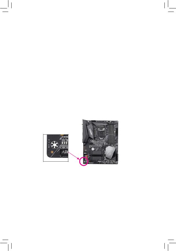
Identifying Your Motherboard Revision
The revision number on your motherboard looks like this: «REV: X.X.» For example, «REV: 1.0» means the revision of the motherboard is 1.0. Check your motherboard revision before updating motherboard BIOS, drivers, or when looking for technical information.
Example:

Table of Contents
|
Z490 UD (AC) Motherboard Layout……………………………………………………………………… |
4 |
|
|
Chapter 1 Hardware Installation………………………………………………………………………….. |
5 |
|
|
1-1 |
Installation Precautions…………………………………………………………………………. |
5 |
|
1-2 |
Product Specifications………………………………………………………………………….. |
6 |
|
1-3 |
Installing the CPU………………………………………………………………………………… |
9 |
|
1-4 |
Installing the Memory……………………………………………………………………………. |
9 |
|
1-5 Installing an Expansion Card……………………………………………………………….. |
10 |
|
|
1-6 |
Back Panel Connectors………………………………………………………………………. |
10 |
|
1-7 |
Internal Connectors……………………………………………………………………………. |
12 |
|
Chapter 2 BIOS Setup……………………………………………………………………………………… |
21 |
|
|
2-1 |
Startup Screen…………………………………………………………………………………… |
21 |
|
2-2 |
The Main Menu………………………………………………………………………………….. |
22 |
|
2-3 |
Favorites (F11)…………………………………………………………………………………… |
23 |
|
2-4 |
Tweaker……………………………………………………………………………………………. |
24 |
|
2-5 |
Settings…………………………………………………………………………………………….. |
29 |
|
2-6 |
System Info……………………………………………………………………………………….. |
35 |
|
2-7 |
Boot…………………………………………………………………………………………………. |
36 |
|
2-8 |
Save & Exit……………………………………………………………………………………….. |
39 |
|
Chapter 3 Appendix…………………………………………………………………………………………. |
40 |
|
|
3-1 Configuring a RAID Set………………………………………………………………………. |
40 |
|
|
3-2 Installing an Intel® Optane™ Memory…………………………………………………….. |
42 |
|
|
3-3 |
Drivers Installation……………………………………………………………………………… |
44 |
|
Regulatory Notices………………………………………………………………………………………. |
45 |
|
|
Contact Us………………………………………………………………………………………………….. |
48 |
— 3 —

Z490 UD (AC) Motherboard Layout
|
ATX_12V_2X2 |
|
|
ATX_12V_2X4 |
CPU_FAN |
|
KB_MS_USB |
|
|
SYS_FAN1 |
D LED2 |
|
CNVIj |
|
|
LGA1200 |
LED_C2 |
|
U32 |
ATX |
|
HDMI |
|
|
U32_G2 |
|
|
U32_LAN |
AUDIO
|
PCIEX1_1 |
(Note) |
|||
|
M2P 32G |
||||
|
PCIEX16 |
||||
|
Realtek® |
||||
|
GbE LAN |
BAT |
|||
|
110 |
80 |
60 |
42 |
|
|
iTE® |
PCIEX4 |
|||
|
Super I/O |
|
U32 |
SYS FAN2 |
|
|
80 |
F_ |
|
|
DDR4 A1 DDR4 A2 DDR4 B1 DDR4 B2 |
|
Z490 UD (AC) |
3 20 |
|
|
1 |
||
|
5 4 |
||
|
M2A SB |
Intel® Z490 |
SATA3 |
PCIEX1_2
CODEC
80 60 42
|
PCIEX1_3 |
||
|
F_AUDIO |
THB_C2 |
|
|
LED_C1 |
||
|
M2M SB |
PLUS |
|
QFLASH_ QFLED |
|
SPDIF |
_O |
THB |
||||||||||||||||
|
SPI_TPM |
F_USB |
|||||||||||||||||
|
_C1 |
F_PANEL |
|||||||||||||||||
|
COM |
D_LED1 |
SYS_FAN4 |
SYS_FAN3 |
|||||||||||||||
|
CPU |
DRAM |
|||||||||||||||||
|
Box Contents |
VGA |
BOOT |
||||||||||||||||
|
55 |
Z490 UD AC or Z490 UD Motherboard |
|||||||||||||||||
|
55 |
Motherboard driver disc |
55 |
Two SATA cables |
|||||||||||||||
|
55 User’s Manual |
55 |
One antennaj |
*The box contents above are for reference only and the actual items shall depend on the product package you obtain. The box contents are subject to change without notice.
(Note) The M.2 connector is reserved only. No functionalities.
jOnly for the Z490 UD AC.
— 4 —

Chapter 1 Hardware Installation
1-1 Installation Precautions
The motherboard contains numerous delicate electronic circuits and components which can become damaged as a result of electrostatic discharge (ESD). Prior to installation, carefully read the user’s manual and follow these procedures:
•• Prior to installation, make sure the chassis is suitable for the motherboard.
•• Prior to installation, do not remove or break motherboard S/N (Serial Number) sticker or warranty sticker provided by your dealer. These stickers are required for warranty validation.
•• Always remove the AC power by unplugging the power cord from the power outlet before installing or removing the motherboard or other hardware components.
•• When connecting hardware components to the internal connectors on the motherboard, make sure they are connected tightly and securely.
•• When handling the motherboard, avoid touching any metal leads or connectors.
•• It is best to wear an electrostatic discharge (ESD) wrist strap when handling electronic components such as a motherboard, CPU or memory. If you do not have an ESD wrist strap, keep your hands dry and first touch a metal object to eliminate static electricity.
•• Prior to installing the motherboard, please have it on top of an antistatic pad or within an electrostatic shielding container.
•• Before connecting or unplugging the power supply cable from the motherboard, make sure the power supply has been turned off.
•• Before turning on the power, make sure the power supply voltage has been set according to the local voltage standard.
•• Before using the product, please verify that all cables and power connectors of your hardware components are connected.
•• To prevent damage to the motherboard, do not allow screws to come in contact with the motherboard circuit or its components.
•• Make sure there are no leftover screws or metal components placed on the motherboard or within the computer casing.
•• Do not place the computer system on an uneven surface.
•• Do not place the computer system in a high-temperature or wet environment.
•• Turning on the computer power during the installation process can lead to damage to system components as well as physical harm to the user.
•• If you are uncertain about any installation steps or have a problem related to the use of the product, please consult a certified computer technician.
•• If you use an adapter, extension power cable, or power strip, ensure to consult with its installation and/or grounding instructions.
— 5 —
|
1-2 |
Product Specifications |
||
|
CPU |
Support for 10th Generation Intel® Core™ i9 processors/Intel® Core™ i7 processors/ |
||
|
Intel® Core™ i5 processors/Intel® Core™ i3 processors/Intel® Pentium® processors/ |
|||
|
Intel® Celeron® processors in the LGA1200 package |
|||
|
L3 cache varies with CPU |
|||
|
Chipset |
Intel® Z490 Express Chipset |
||
|
Memory |
Intel® Core™ i9/i7 processors: |
||
|
— Support for DDR4 3200/3000/2933/2666/2400/2133 MHz memory modules |
|||
|
Intel® Core™ i5/i3/Pentium®/Celeron® processors: |
|||
|
— Support for DDR4 2666/2400/2133 MHz memory modules |
|||
|
4 x DDR4 DIMM sockets supporting up to 128 GB (32 GB single DIMM capacity) |
|||
|
of system memory |
|||
|
Dual channel memory architecture |
|||
|
Support for ECC Un-buffered DIMM 1Rx8/2Rx8 memory modules (operate in |
|||
|
non-ECC mode) |
|||
|
Support for non-ECC Un-buffered DIMM 1Rx8/2Rx8/1Rx16 memory modules |
|||
|
Support for Extreme Memory Profile (XMP) memory modules |
|||
|
(Go to GIGABYTE’s website for the latest supported memory speeds and memory |
|||
|
modules.) |
|||
|
Onboard |
Integrated Graphics Processor-Intel® HD Graphics support: |
||
|
Graphics |
— 1 x HDMI port, supporting a maximum resolution of 4096×2160@30 Hz |
||
|
* Support for HDMI 1.4 version and HDCP 2.3. |
Maximum shared memory of 512 MB
|
Audio |
Realtek® ALC887 codec |
|
|
High Definition Audio |
||
|
2/4/5.1/7.1-channel |
*To configure 7.1-channel audio, you need to open the audio software and select Device advanced settings > Playback Device to change the default setting first. Please visit GIGABYTE’s website for details on configuring the audio software.
Support for S/PDIF Out
|
LAN |
Realtek® GbE LAN chip (1000 Mbit/100 Mbit) |
|
|
Wireless |
Intel® Wi-Fi AC 9462: |
|
|
Communication |
— |
Intel® CNVi interface 802.11a/b/g/n/ac, supporting 2.4/5 GHz Dual-Band |
|
Modulej |
— |
BLUETOOTH 5 |
|
— |
Support for 1×1 11ac wireless standard and up to 433 Mbps data rate |
|
|
* Actual data rate may vary depending on environment and equipment. |
||
|
Expansion Slots |
1 x PCI Express x16 slot, running at x16 (PCIEX16) |
|
|
* For optimum performance, if only one PCI Express graphics card is to be installed, |
||
|
be sure to install it in the PCIEX16 slot. |
||
|
1 x PCI Express x16 slot, running at x4 (PCIEX4) |
||
|
3 x PCI Express x1 slots |
||
|
(All of the PCI Express slots conform to PCI Express 3.0 standard.) |
||
|
Multi-Graphics |
Support for AMD Quad-GPU CrossFire™ and 2-Way AMD CrossFire™ technologies |
|
|
Technology |
Storage Interface 1 x M.2 connector (Socket 3, M key, type 2242/2260/2280/22110 SATA and PCIe x4/x2 SSD support) (M2A_SB)
1 x M.2 connector (Socket 3, M key, type 2242/2260/2280 PCIe x4/x2 SSD support) (M2M_SB)
6 x SATA 6Gb/s connectors
j Only for the Z490 UD AC.
— 6 —
|
Storage Interface |
Support for RAID 0, RAID 1, RAID 5, and RAID 10 |
||
|
* Refer to «1-7 Internal Connectors,» for the installation notices for the M.2 and SATA |
|||
|
connectors. |
|||
|
Intel® Optane™ Memory Ready |
|||
|
USB |
Chipset: |
||
|
— |
1 x USB 3.2 Gen 2 Type-A port (red) on the back panel |
||
|
— |
7 x USB 3.2 Gen 1 ports (5 ports on the back panel, 2 ports available through |
||
|
the internal USB header) |
|||
|
— |
4 x USB 2.0/1.1 ports (2 ports on the back panel, 2 ports available through |
||
|
the internal USB header) |
|||
|
Internal |
1 x 24-pin ATX main power connector |
||
|
Connectors |
1 x 4-pin ATX 12V power connector |
||
|
1 x 8-pin ATX 12V power connector |
|||
|
1 x CPU fan header |
|||
|
4 x system fan headers |
|||
|
2 x addressable LED strip headers |
|||
|
2 x RGB LED strip headers |
|||
|
1 x Q-Flash Plus button |
|||
|
6 x SATA 6Gb/s connectors |
|||
|
2 x M.2 Socket 3 connectors |
|||
|
1 x front panel header |
|||
|
1 x front panel audio header |
|||
|
1 x S/PDIF Out header |
|||
|
1 x USB 3.2 Gen 1 header |
|||
|
1 x USB 2.0/1.1 header |
|||
|
1 x Trusted Platform Module header (For the GC-TPM2.0 SPI/GC-TPM2.0 SPI |
|||
|
2.0 module only) |
|||
|
2 x Thunderbolt™ add-in card connectors |
|||
|
1 x serial port header |
|||
|
1 x Clear CMOS jumper |
|||
|
Back Panel |
1 x PS/2 keyboard/mouse port |
||
|
Connectors |
2 x SMA antenna connectors (1T1R)j |
||
|
1 x HDMI port |
|||
|
1 x USB 3.2 Gen 2 Type-A port (red) |
|||
|
5 x USB 3.2 Gen 1 ports |
|||
|
2 x USB 2.0/1.1 ports |
|||
|
1 x RJ-45 port |
|||
|
3 x audio jacks |
|||
|
I/O Controller |
iTE® I/O Controller Chip |
||
|
Hardware |
Voltage detection |
||
|
Monitor |
Temperature detection |
||
|
Fan speed detection |
|||
|
Overheating warning |
|||
|
Fan fail warning |
|||
|
Fan speed control |
|||
|
* Whether the fan speed control function is supported will depend on the cooler you |
|||
|
install. |
j Only for the Z490 UD AC.
— 7 —
|
BIOS |
1 x 256 Mbit flash |
|||
|
Use of licensed AMI UEFI BIOS |
||||
|
PnP 1.0a, DMI 2.7, WfM 2.0, SM BIOS 2.7, ACPI 5.0 |
||||
|
Unique Features |
Support for APP Center |
|||
|
* Available applications in APP Center may vary by motherboard model. |
||||
|
Supported functions of each application may also vary depending on |
||||
|
motherboard specifications. |
||||
|
— |
@BIOS |
|||
|
— |
EasyTune |
|||
|
— |
Fast Boot |
|||
|
— |
Game Boost |
|||
|
— |
ON/OFF Charge |
|||
|
— |
RGB Fusion |
|||
|
— |
Smart Backup |
|||
|
— |
System Information Viewer |
|||
|
Support for Q-Flash Plus |
||||
|
Support for Q-Flash |
||||
|
Support for Xpress Install |
||||
|
Bundled |
Norton® Internet Security (OEM version) |
|||
|
Software |
Realtek® 8118 Gaming LAN Bandwidth Control Utility |
|||
|
Operating |
Support for Windows 10 64-bit |
|||
|
System |
||||
|
Form Factor |
ATX Form Factor; 30.5cm x 24.4cm |
*GIGABYTE reserves the right to make any changes to the product specifications and product-related information without prior notice.
Please visit GIGABYTE’s website for support lists of CPU, memory modules,
SSDs, and M.2 devices.
Please visit the SupportUtility List page on GIGABYTE’s website to download the latest version of apps.
— 8 —
|
1-3 |
Installing the CPU |
|
|
Read the following guidelines before you begin to install the CPU: |
||
|
•• |
Make sure that the motherboard supports the CPU. |
|
|
(Go to GIGABYTE’s website for the latest CPU support list.) |
||
|
•• |
Always turn off the computer and unplug the power cord from the power outlet before installing the |
|
|
CPU to prevent hardware damage. |
||
|
•• |
Locate the pin one of the CPU. The CPU cannot be inserted if oriented incorrectly. (Or you may |
|
|
locate the notches on both sides of the CPU and alignment keys on the CPU socket.) |
||
|
•• |
Apply an even and thin layer of thermal grease on the surface of the CPU. |
|
|
•• |
Do not turn on the computer if the CPU cooler is not installed, otherwise overheating and damage |
|
|
of the CPU may occur. |
||
|
•• |
Set the CPU host frequency in accordance with the CPU specifications. It is not recommended |
|
|
that the system bus frequency be set beyond hardware specifications since it does not meet the |
||
|
standard requirements for the peripherals. If you wish to set the frequency beyond the standard |
||
|
specifications, please do so according to your hardware specifications including the CPU, graphics |
||
|
card, memory, hard drive, etc. |
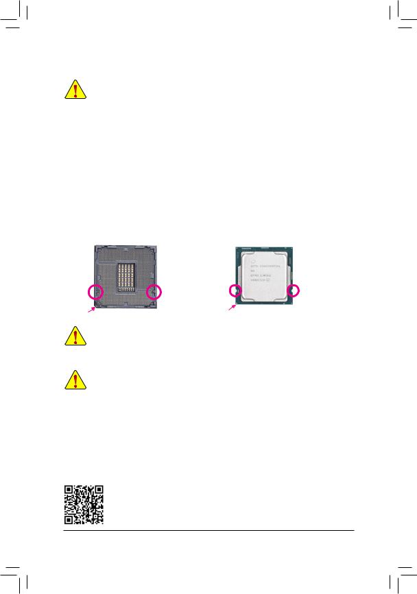
Installing the CPU
Locate the alignment keys on the motherboard CPU socket and the notches on the CPU.
|
LGA1200 CPU Socket |
LGA1200 CPU |
|
Alignment |
Alignment |
Notch |
Notch |
|
Key |
Key |
||
|
Pin One Corner of the CPU Socket |
Triangle Pin One Marking on the CPU |
Do not remove the CPU socket cover before inserting the CPU. It may pop off from the load plate automatically during the process of re-engaging the lever after you insert the CPU.
1-4 Installing the Memory
Read the following guidelines before you begin to install the memory:
•• Make sure that the motherboard supports the memory. It is recommended that memory of the same capacity, brand, speed, and chips be used.
(Go to GIGABYTE’s website for the latest supported memory speeds and memory modules.)
•• Always turn off the computer and unplug the power cord from the power outlet before installing the memory to prevent hardware damage.
•• Memory modules have a foolproof design. A memory module can be installed in only one direction. If you are unable to insert the memory, switch the direction.
Dual Channel Memory Configuration
This motherboard provides four memory sockets and supports Dual Channel Technology. After the memory is installed, the BIOS will automatically detect the specifications and capacity of the memory. Enabling Dual
Channel memory mode will double the original memory bandwidth.
Please visit GIGABYTE’s website for details on hardware installation.
— 9 —
The four memory sockets are divided into two channels and each channel has two memory sockets as following:
Channel A: DDR4_A1, DDR4_A2Channel B: DDR4_B1, DDR4_B2
Recommanded Dual Channel Memory Configuration:
|
DDR4_A1 |
DDR4_A2 |
DDR4_B1 |
DDR4_B2 |
|
|
2 Modules |
— — |
DS/SS |
— — |
DS/SS |
|
4 Modules |
DS/SS |
DS/SS |
DS/SS |
DS/SS |
(SS=Single-Sided, DS=Double-Sided, «- -«=No Memory)
Due to CPU limitations, read the following guidelines before installing the memory in Dual Channel mode.
1.Dual Channel mode cannot be enabled if only one memory module is installed.
2.When enabling Dual Channel mode with two or four memory modules, it is recommended that memory of the same capacity, brand, speed, and chips be used.
1-5 Installing an Expansion Card
Read the following guidelines before you begin to install an expansion card:
•• Make sure the motherboard supports the expansion card. Carefully read the manual that came with your expansion card.
•• Always turn off the computer and unplug the power cord from the power outlet before installing an expansion card to prevent hardware damage.
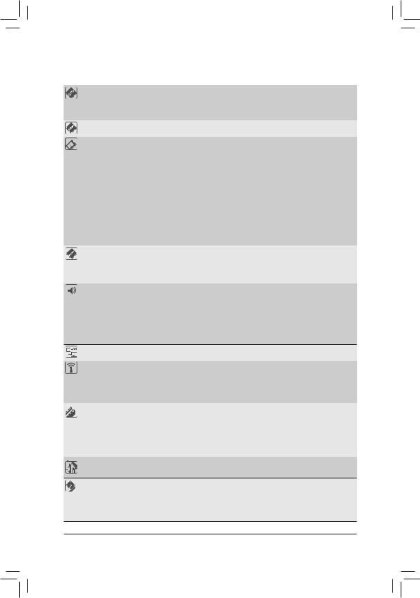
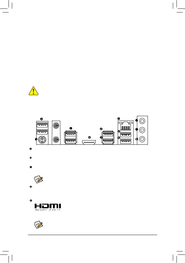
1-6 Back Panel Connectors
 j
j
USB 2.0/1.1 Port
The USB port supports the USB 2.0/1.1 specification. Use this port for USB devices.
PS/2 Keyboard/Mouse Port
Use this port to connect a PS/2 mouse or keyboard.
SMA Antenna Connectors (1T1R)j
Use this connector to connect an antenna.

 Tighten the antennas to the antenna connectors and then aim the antennas correctly for better
signal reception.
USB 3.2 Gen 1 Port
The USB 3.2 Gen 1 port supports the USB 3.2 Gen 1 specification and is compatible to the USB 2.0 specification. Use this port for USB devices.
HDMI Port
 The HDMI port supports HDCP 2.3 and Dolby TrueHD and DTS HD Master Audio
formats. It also supports up to 192KHz/16bit 7.1-channel LPCM audio output.
You can use this port to connect your HDMI-supported monitor. The maximum supported resolution is
4096×2160@30 Hz, but the actual resolutions supported are dependent on the monitor being used.

 After installing the HDMI device, make sure to set the default sound playback device to HDMI.
 (The item name may differ depending on your operating system.) j Only for the Z490 UD AC.
— 10 —
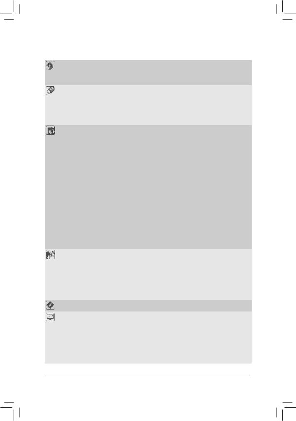
![]()
USB 3.2 Gen 2 Type-A Port (Red)
The USB 3.2 Gen 2 Type-A port supports the USB 3.2 Gen 2 specification and is compatible to the USB 3.2 Gen 1 and USB 2.0 specification. Use this port for USB devices.
RJ-45 LAN Port
The Gigabit Ethernet LAN port provides Internet connection at up to 1 Gbps data rate. The following describes the states of the LAN port LEDs.
|
Connection/ |
Connection/Speed LED: |
Activity LED: |
|||||||||||||||||
|
Speed LED |
Activity LED |
||||||||||||||||||
|
State |
Description |
State |
Description |
||||||||||||||||
|
Orange |
1 Gbps data rate |
Blinking |
Data transmission or receiving is occurring |
||||||||||||||||
|
Green |
100 Mbps data rate |
Off |
No data transmission or receiving is occurring |
||||||||||||||||
|
Off |
10 Mbps data rate |
||||||||||||||||||
|
LAN Port |
|||||||||||||||||||
USB 3.2 Gen 1 Type-A Port (Q-Flash Plus Port)
The USB port supports the USB 3.2 Gen 1 specification. Use this port for USB devices. Before using Q-Flash Plus (Note), make sure to insert the USB flash drive into this port first.
Line In/Rear Speaker Out (Blue)
The line in jack. Use this audio jack for line in devices such as an optical drive, walkman, etc.
Line Out/Front Speaker Out (Green)
The line out jack.
Mic In/Center/Subwoofer Speaker Out (Pink)
The Mic in jack.
Audio Jack Configurations:
|
Jack |
Headphone/ |
4-channel |
5.1-channel |
7.1-channel |
|
|
2-channel |
|||||
|
Line In/Rear Speaker Out |
a |
a |
a |
||
|
Line Out/Front Speaker Out |
a |
a |
a |
a |
|
|
Mic In/Center/Subwoofer Speaker Out |
a |
a |
|||
|
Front Panel Line Out/Side Speaker Out |
a |
||||
•• When removing the cable connected to a back panel connector, first remove the cable from your device and then remove it from the motherboard.
•• When removing the cable, pull it straight out from the connector. Do not rock it side to side to prevent an electrical short inside the cable connector.
|
(Note) |
To enable the Q-Flash Plus function please visit the «Unique Features» webpage of GIGABYTE’s website. |
Please visit GIGABYTE’s website for details on configuring the audio software.
— 11 —
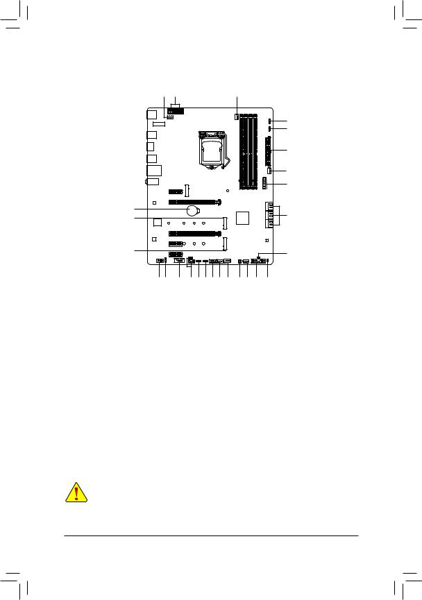
1-7 Internal Connectors
|
4 |
1 |
3 |
||||||
|
5 |
||||||||
|
6 |
||||||||
|
2 |
||||||||
|
4 |
||||||||
|
12 |
||||||||
|
19 |
7 |
|||||||
|
8 |
||||||||
|
8 |
18 |
|||||||
|
10 11 |
15 |
14 |
5 |
6 16 4 |
13 |
17 4 |
9 |
20 |
|
1) |
ATX_12V_2X2/ATX_12V_2X4 |
11) |
SPDIF_O |
|
2) |
ATX |
12) |
F_U32 |
|
3) |
CPU_FAN |
13) |
F_USB |
|
4) |
SYS_FAN1/2/3/4 |
14) |
THB_C1/THB_C2 |
|
5) |
D_LED1/D_LED2 |
15) |
COM |
|
6) |
LED_C1/LED_C2 |
16) |
SPI_TPM |
|
7) |
SATA3 0/1/2/3/4/5 |
17) |
QFLASH_PLUS |
|
|
M2A_SB/M2M_SB |
18) |
CLR_CMOS |
|
9) |
F_PANEL |
19) |
BAT |
|
10) |
F_AUDIO |
20) |
CPU/DRAM/VGA/BOOT |
Read the following guidelines before connecting external devices:
•• First make sure your devices are compliant with the connectors you wish to connect.
•• Before installing the devices, be sure to turn off the devices and your computer. Unplug the power cord from the power outlet to prevent damage to the devices.
•• After installing the device and before turning on the computer, make sure the device cable has been securely attached to the connector on the motherboard.
— 12 —
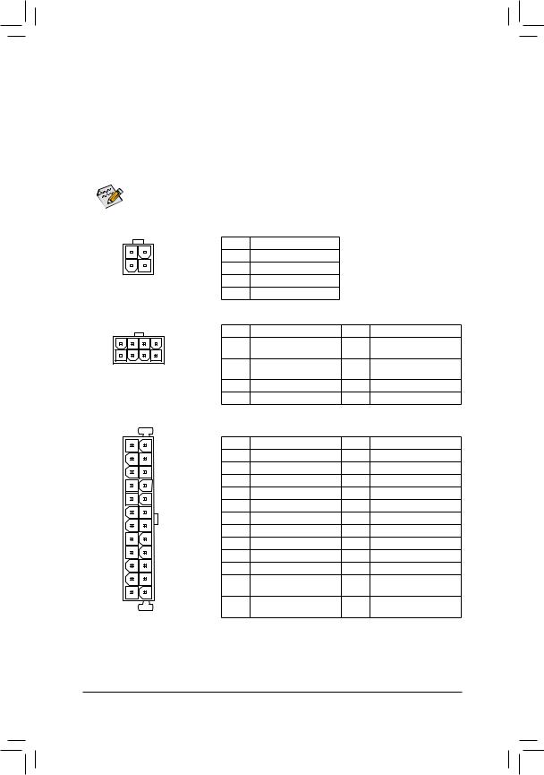
1/2) ATX_12V_2X2/ATX_12V_2X4/ATX (2×2, 2×4, 12V Power Connectors and 2×12 Main Power
Connector)
With the use of the power connector, the power supply can supply enough stable power to all the components on the motherboard. Before connecting the power connector, first make sure the power supply is turned off and all devices are properly installed. The power connector possesses a foolproof design. Connect the power supply cable to the power connector in the correct orientation.
The 12V power connector mainly supplies power to the CPU. If the 12V power connector is not connected, the computer will not start.
To meet expansion requirements, it is recommended that a power supply that can withstand high power consumption be used (500W or greater). If a power supply is used that does not provide the required power, the result can lead to an unstable or unbootable system.
|
3 |
4 |
|
1 |
2 |
|
ATX_12V_2X2 |
|
|
5 |
8 |
|
1 |
4 |
|
ATX_12V_2X4 |
ATX
ATX_12V_2X2:
|
Pin No. |
Definition |
||
|
1 |
GND |
||
|
2 |
GND |
||
|
3 |
+12V |
||
|
4 |
+12V |
||
|
ATX_12V_2X4: |
|||
|
Pin No. |
Definition |
Pin No. |
Definition |
|
1 |
GND (Only for 2×4-pin 12V) |
5 |
+12V (Only for 2×4-pin |
|
12V) |
|||
|
2 |
GND (Only for 2×4-pin 12V) |
6 |
+12V (Only for 2×4-pin |
|
12V) |
|||
|
3 |
GND |
7 |
+12V |
|
4 |
GND |
8 |
+12V |
|
ATX: |
|||
|
Pin No. |
Definition |
Pin No. |
Definition |
|
1 |
3.3V |
13 |
3.3V |
|
2 |
3.3V |
14 |
-12V |
|
3 |
GND |
15 |
GND |
|
4 |
+5V |
16 |
PS_ON (soft On/Off) |
|
5 |
GND |
17 |
GND |
|
6 |
+5V |
18 |
GND |
|
7 |
GND |
19 |
GND |
|
8 |
Power Good |
20 |
NC |
|
9 |
5VSB (stand by +5V) |
21 |
+5V |
|
10 |
+12V |
22 |
+5V |
|
11 |
+12V (Only for 2×12-pin |
23 |
+5V (Only for 2×12-pin |
|
ATX) |
ATX) |
||
|
12 |
3.3V (Only for 2×12-pin |
24 |
GND (Only for 2×12-pin |
|
ATX) |
ATX) |
— 13 —
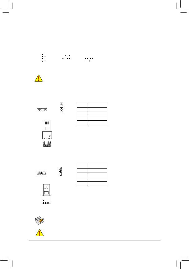
3/4) CPU_FAN/SYS_FAN1/2/3/4 (Fan Headers)
All fan headers on this motherboard are 4-pin. Most fan headers possess a foolproof insertion design. When connecting a fan cable, be sure to connect it in the correct orientation (the black connector wire is the ground wire). The speed control function requires the use of a fan with fan speed control design. For optimum heat dissipation, it is recommended that a system fan be installed inside the chassis.
|
Pin No. |
Definition |
|||||||||||||
|
1 |
1 |
1 |
GND |
|||||||||||
|
1 |
2 |
Voltage Speed Control |
||||||||||||
|
CPU_FAN/SYS_FAN2 |
SYS_FAN1 |
SYS_FAN3/SYS_FAN4 |
3 |
Sense |
||||||||||
|
4 |
PWM Speed Control |
•• Be sure to connect fan cables to the fan headers to prevent your CPU and system from overheating. Overheating may result in damage to the CPU or the system may hang.
•• Thesefanheadersarenotconfigurationjumperblocks.Donotplaceajumpercapontheheaders.
5)D_LED1/D_LED2 (Digital LED Strip Headers)
The headers can be used to connect a standard 5050 addressable LED strip, with maximum power rating of 5A (5V) and maximum number of 1000 LEDs.
|
Pin No. |
Definition |
|
1 |
V (5V) |
|
2 |
D |
|
3 |
No Pin |
|
4 |
G |
Connect your addressable LED strip to the header. The power pin (marked with a triangle on the plug) of the LED strip must be connected to Pin 1 of the addressable LED strip header. Incorrect connection may lead to the damage of the LED strip.
6)LED_C1/LED_C2 (RGB LED Strip Headers)
The headers can be used to connect a standard 5050 RGB LED strip (12V/G/R/B), with maximum power rating of 2A (12V) and maximum length of 2m.
RGB LED Strip
1 
12V
|
Pin No. |
Definition |
|
1 |
12V |
|
2 |
G |
|
3 |
R |
|
4 |
B |
Connect your RGB LED strip to the header. The power pin (marked with a triangle on the plug) of the LED strip must be connected to Pin 1 (12V) of this header. Incorrect connection may lead to the damage of the LED strip.
 For how to turn on/off the lights of the LED strip please visit the «Unique Features» webpage of
GIGABYTE’s website.
Before installing the devices, be sure to turn off the devices and your computer. Unplug the power cord from the power outlet to prevent damage to the devices.
— 14 —
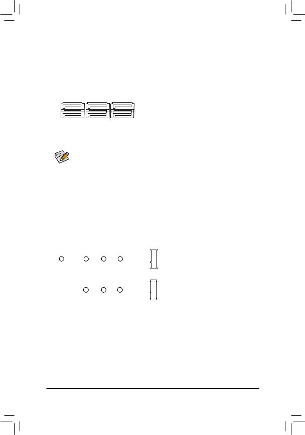
7)SATA3 0/1/2/3/4/5 (SATA 6Gb/s Connectors)
The SATA connectors conform to SATA 6Gb/s standard and are compatible with SATA 3Gb/s and SATA 1.5Gb/s standard. Each SATA connector supports a single SATA device. The Intel® Chipsetsupports RAID0, RAID 1, RAID 5, and RAID 10. Refer to Chapter 3, «Configuring a RAID Set,» for instructions on configuring a RAID array.
|
Pin No. |
Definition |
|||||
|
SATA3 |
5 |
3 |
1 |
|||
|
1 |
GND |
|||||
|
4 |
2 |
0 |
||||
|
7 |
1 |
2 |
TXP |
|||
|
3 |
TXN |
|||||
|
7 |
1 |
4 |
GND |
|||
|
5 |
RXN |
|||||
|
6 |
RXP |
|||||
|
7 |
GND |
To enable hot-plugging for the SATA ports, refer to Chapter 2, «BIOS Setup,» «SettingsIO Ports SATAAnd RST Configuration,» for more information.
 M2A_SB/M2M_SB (M.2 Socket 3 Connectors)
The M.2 connectors support M.2 SATA SSDs or M.2 PCIe SSDs and support RAID configuration. Please note that an M.2 PCIe SSD cannot be used to create a RAID set either with an M.2 SATA SSD or a SATA hard drive. To create a RAID array with an M.2 PCIe SSD, you must set up the configuration in UEFI BIOS mode. Refer to Chapter 3, «Configuring a RAID Set,» for instructions on configuring a RAID array.
M2A_SB
M2M_SB
Follow the steps below to correctly install an M.2 SSD in the M.2 connector.
Step 1:
Use a screw driver to unfasten the screw and standoff from the motherboard. Locate the proper mounting hole for the M.2 SSD to be installed and then screw the standoff first.
Step 2:
Slide the M.2 SSD into the connector at an angle. Step 3:
Press the M.2 SSD down and then secure it with the screw.
— 15 —
|
Код: 124288 Извините, товара сейчас нет в наличии
Бесплатная доставка
Извините, товара сейчас нет в наличии Сравнить Новости интернет-магазина «Лаукар»:28.03.2023 22.02.2023 13.02.2023 Дополнительная информация в категории Материнская плата:Таблица Авторизованных сервисных центров по брендам. Описание Инструкция Отзывы (0) В интернет-магазине бытовой техники «Лаукар» Вы можете скачать инструкцию к товару Материнская плата GIGABYTE Z490 UD совершенно бесплатно. Все инструкции, представленные на сайте интернет-магазина бытовой техники «Лаукар», предоставляются производителем товара. Для того чтобы скачать инструкцию, Вам необходимо нажать на ссылку «скачать инструкцию», расположенную ниже, а в случае, если ссылки нет, Скачать инструкцию Смотреть инструкцию
Фирма-производитель оставляет за собой право на внесение изменений в конструкцию, дизайн и комплектацию товара: Материнская плата GIGABYTE Z490 UD. Пожалуйста, сверяйте информацию о товаре с информацией на |